

Page 1
INSTALLATION INSTRUCTIONS
MODEL RXGY-G01 (SP20286)
DIRECT VENT – SIDE WALL VENT KIT
FOR USE WITH (-)GRA, (-)GRJ, (-)GTA, (-)GTJ, (-)GFD, (-)GGD, (-)GRK,
(-)GTK, (-)GRS, (-)GTS, (-)GFE, (-)GGE, (-)GFG, (-)GJF, (-)GRL,
(-)GRM, (-)GTM, (-)GTC, (-)GRC & (-)GRB FURNACES
FOR USE WITH CONDENSING TANKLESS WATER HEATERS PER
MANUFACTURE INSTRUCTION
KIT CONTENTS:
• Vent Cap
• Vent Plate
• Mounting Hardware
NOTE: Field-supplied pipe and fittings are
required to complete the installation.
!
WARNING
THIS VENT KIT MUST BE INSTALLED BY A QUALIFIED SERVICE TECHNICIAN. CODES AND LOCAL UTILITY
REQUIREMENTS GOVERNING THE INSTALLATION OF GAS FIRED EQUIPMENT, WIRING, PLUMBING, AND FLUE
CONNECTIONS MUST BE ADHERED TO. IN THE ABSENCE OF LOCAL CODES, THE INSTALLATION MUST CONFORM
WITH THE NATIONAL FUEL GAS CODE ANSI Z223.1 “LATEST EDITION,” OR CAN/CGA B149 INSTALLATION CODES.
THE LATEST CODE MAY BE OBTAINED FROM THE INTERNATIONAL APPROVAL SERVICES, 8501 E. PLEASANT
VALLEY RD., CLEVELAND, OHIO 44131, OR 55 SCARSDALE RD., TORONTO, ONTARIO, CANADA, M3B 2R3.
This manual covers the installation of the RXGY-G01
Direct Vent Furnace – Side Wall Vent Kit. The
RXGY-G01 Vent Kit can be used for all above listed
furnace models or gas fired Direct Vent Condensing
Tankless Water Heaters, excluding models featuring
alternate terminations. See vent application charts in
applicable furnace installation instructions.
IMPORTANT:
!
WARNING
DO NOT OPERATE THE FURNACE OR TANKLESS WATER HEATER WITHOUT THE SIDE WALL CAP IN PLACE AS
RECIRCULATION OF COMBUSTION PRODUCTS MAY OCCUR. WATER MAY ALSO COLLECT INSIDE THE COMBUSTION AIR PIPE AND FLOW TO THE BURNER ENCLOSURE. FAILURE TO FOLLOW THIS WARNING COULD RESULT IN
PRODUCT DAMAGE OR IMPROPER OPERATION, PERSONAL INJURY OR DEATH.
!
WARNING
THESE INSTRUCTIONS ARE INTENDED AS AN AID TO QUALIFIED SERVICE PERSONNEL FOR PROPER INSTALLATION, ADJUSTMENT AND OPERATION OF THIS UNIT. READ THESE INSTRUCTIONS THOROUGHLY BEFORE
ATTEMPTING INSTALLATION OR OPERATION. FAILURE TO FOLLOW THESE INSTRUCTIONS MAY RESULT IN
IMPROPER INSTALLATION, ADJUSTMENT, SERVICE OR MAINTENANCE, POSSIBLY RESULTING IN FIRE, CARBON
MONOXIDE POISONING, EXPLOSION, PROPERTY DAMAGE, PERSONAL INJURY OR DEATH.
DO NOT DESTROY THIS MANUAL. PLEASE READ CAREFULLY AND KEEP
IN A SAFE PLACE FOR FUTURE REFERENCE BY A SERVICEMAN.
SUPERSEDES 92-102005-01-00
92-102005-01-01
Page 2
INSTALLATION - Side Wall Vent Kit
IMPORTANT: Refer to Furnace or Condensing Tankless Water Heater Installation Instructions for complete information on installation
of Side Vent Kit. (See Figures 1-3.) All applicable codes should be followed when determining vent location.
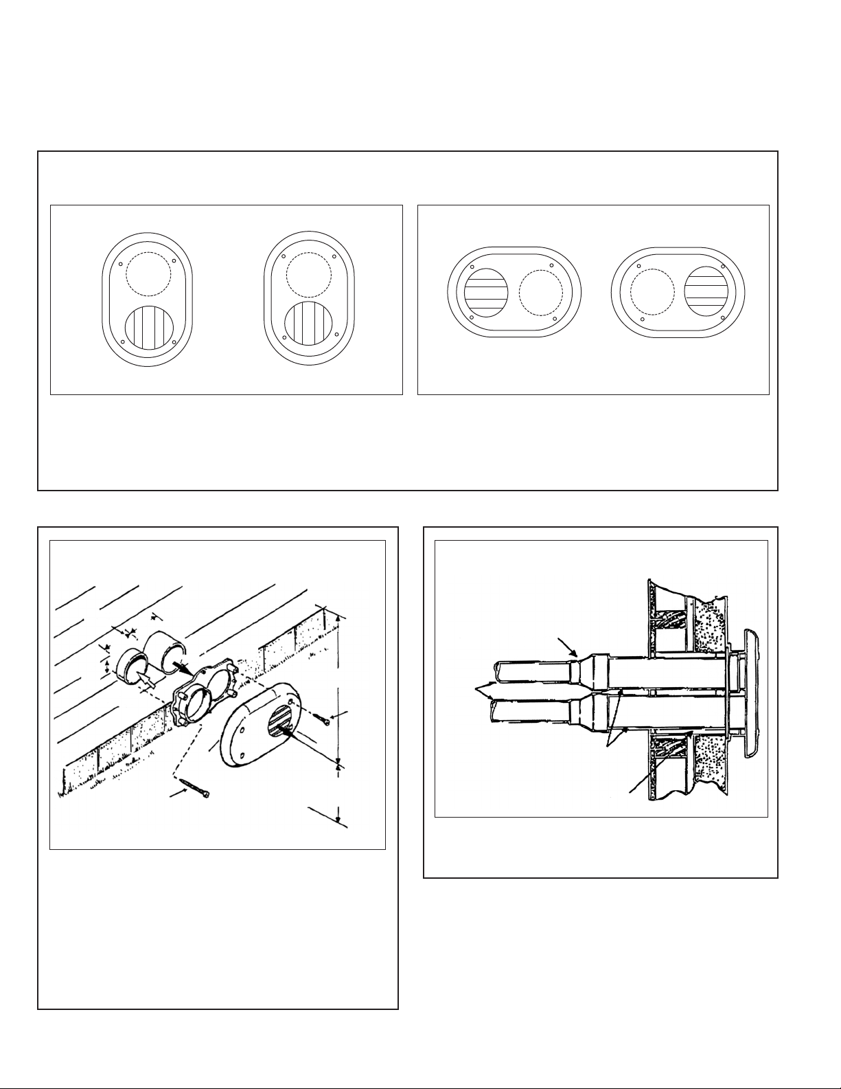
FIGURE 1
ENT KIT INSTALLATION OPTIONS
V
OPTION A
TYPICAL VERTICAL INSTALLATION
OPTION B
TYPICAL HORIZONTAL INSTALLATION
NOTE: Install the vent and air intake piping into the vent plate openings. Seal all gaps between the pipes and wall. Use silicon
sealant to seal the vent pipe to the vent cap to permit field disassembly for cleaning. Also seal all pipe penetrations in wall. To prevent possibility of condensate freeze-up, do not install vent kits one above the other.
FIGURE 2
TYPICAL SIDE WALL APPLICATION
ANCHORS
(4 req.)
2.53"
COMBUSTION
"
.53
4
"
.53
4
VENT
AIR
VENT
PLATE
12" MINIMUM
TO OVERHANG
1" SCREWS
(4 req.)
FIGURE 3
TOP VIEW – TYPICAL INSTALLATION
REDUCING
COUPLING,
FIELD SUPPLIED
IF NEEDED
2", 2-1/2"
or 3" PIPING
VENT
2" SCREWS
(4 req.)
VENT
CAP
MAINTAIN12" (18" FORCANADA) MINIMUM
CLEARANCE ABOVE HIGHEST ANTICIPATED
SNOW LEVEL OR GRADE WHICHEVER IS GREATER
Use the vent plate as a template to locate the vent and air
intakes holes and four mounting holes. Cut two 3-7/8 inch
diameter holes for the vent and air intake openings. Drill four
3/16ⴖ diameter holes for inserting the plastic anchors into the
wall. Attach the vent plate to the wall with four screws (#8
pan, 2ⴖ long, SMS Type A18-8 stainless steel).
Assemble the vent cap to the vent plate. Insert the four (#8
pan, 1ⴖ long, SMS Type A18-8 stainless steel) screws into
the vent cap screw hole openings and securely attach the
vent cap to the vent plate.
2
3" PIPING
SEAL ALL
WALL CAVITIES
NOTE: Reducing couplings are required, but not supplied,
for pipe reduction.
CM 0111
 Loading...