

Rheem RXGJ-FP34 Installation Manual
INSTALLATION INSTRUCTIONS
90 PLUS TWO-STAGE GAS VALVE
WITH DIRECT SPARK IGNITION
RXGJ-FP34
BEFORE INSTALLING THIS KIT, CHECK THE “CONVERSION KIT INDEX” (92-21519-69) TO BE SURE YOU
HAVE THE RIGHT KIT FOR THE FURNACE MODEL YOU ARE CONVERTING.
TO CONVERT FROM NATURAL TO LP GAS
USE KIT NUMBER FP34 (US/CANADIAN)
PARTS LIST
DESCRIPTION PART NUMBER FP34
Installation Instructions 92-104444-01 1
Conversion Label 92-18153-05 1
WR LP Conversion Kit 92-1008 60-21193-06 1
Orifice - Burner (1.10 mm) 62-22175-90 8
Recognize this symbol as an indication of Important Safety Information!
!
!
WARNING
THESE INSTRUCTIONS ARE INTENDED AS AN AID TO QUALIFIED, LICENSED SERVICE PERSONNEL FOR PROPER INSTALLATION, ADJUSTMENT AND OPERATION OF THIS UNIT. READ THESE INSTRUCTIONS THOR OUGHLY
BEFORE ATTEMPTING ANY MAINTENANCE OR OPERATION. FAILURE TO FOLLOW THESE INSTRUCTIONS CAN
RESULT IN IMPROPER INSTALLATION, ADJUSTMENT, SERVICE OR MAINTENANCE RESULTING IN FIRE, ELECTRICAL SHOCK, CARBON MONOXIDE POISONING, EXPLOSION, PROPERTY DAMAGE, PERSONAL INJURY OR
DEATH.
FOR CANADIAN INSTALLATIONS, THE CONVERSION SHALL BE CARRIED OUT BY A MANUFACTURER’S
AUTHORIZED REPRESENTATIVE, IN ACCORDANCE WITH REQUIREMENTS OF THE MANUFACTURER, PROVINCIAL OR TERRITORIAL AUTHORITIES HAVING JURISDICTION AND IN ACCORDANCE WITH THE REQUIREMENTS
OF THE CAN/CGA-B149.1 OR CAN/CGA-B149.2 INSTALLATION CODES.
!
WARNING
TURN OFF ELECTRICAL POWER AND MAIN GAS SUPPLY
BEFORE BEGINNING MODIFICATION. FAILURE TO DO
SO CAN RESULT IN ELECTRICAL SHOCK OR EXPLOSION CA U S I N G P R O P E R T Y DAMAGE, PERSONAL
INJURY OR DEATH.
IMPORTANT: DAMAGE TO THE PRODUCT RESULTING
FROM FAILURE TO FOLLOW INSTRUCTIONS OR USE OF
UNAUTHORIZED PARTS MAY BE EXCLUDED FROM THE
MANUFACTURER’S PRODUCT WARRANTY COVERAGE.
The main burner orifices must be sized as shown below.
FURNACE INPUT
BTU/HR
42000 - 112000
1.10 MM
In USA: All gas piping must comply with the latest NFPA 54
National Fuel Gas Code and all state and local codes. All electrical wiring must comply with the latest NFPA 70, National
Electrical code and all state and local codes.
ELEVATION (FEET)
5000’-7999’0’-4999’
#60 #62 #63
8000’-9000’ 9000’ – 10K
In Canada: All gas piping must comply with the latest CAN1B149-1 & 2 installation codes for gas burning appliances and
all provincial and local codes, Part 1 – CSA Standard C22.1
and all provincial and local codes.
KIT INSTALLATION
1.
!
WARNING
TURN OFF ELECTRICAL POWER AND MAIN GAS
SUPPLY BEFORE BEGINNING MODIFICATION. FAILURE TO DO SO CAN RE S U L T IN ELECTRICAL
SHOCK OR EXPLOSION CAUSING PROPERTY DAMAGE, PERSONAL INJURY OR DEATH.
2. Disconnect union ahead of combination gas valve.
3. Disconnect leads from gas valve.
4. Remove the 4 screws holding the manifold assembly to
the main burner assembly.
5. Install springs into gas valve per instructions included
with the spring kit.
6. Remove each existing orifice from the manifold assembly
using a ratchet with a 7/16 socket. Replace with orifices
from the kit. Screw the orifices in hand tight and secure in
place with a quarter turn with the ratchet.
SUPERSEDES 92-104444-01-00
92-104444-01-01
7. Reinstall the manifold assembly on the burner assembly
with the 4 screws removed in step 4.
8. Reconnect the leads to the gas valve, union, and electrical power to furnace.
9. Turn on the gas supply and check unit thoroughly for gas
leaks using soap solution.
10. Follow lighting instructions to put furnace into operation.
11. Operate thermostat to check unit operation.
!
WARNING
DO NOT USE AN OPEN FLAME.
NOTE: If you have a single thermostat, the furnace will
tart on high fire then switches to low fire and will continue
s
on low fire for 12 minutes and then if thermostat is not satisfied, shifts to high fire. With a 2-stage thermostat, when
there is a call for low heat (1st stage), the furnace will start
on high fire then switch to low fire until the call for heat is
satisfied or 2nd stage contacts close.
CHECKING AND ADJUSTING GAS
PRESSURE
1. The LP gas supply pressure must be set between 11 and
13” W.C. by means of the tank or branch supply regulators.
2. The furnace manifold pressure should be 10” W.C. for high
fire and 4.8” W.C. for low fire. These pressures can be
checked by connecting a properly calibrated manometer or
gauge to the manifold pressure tap on the outlet end of the
valve. Check and adjust pressures as follows:
a. For full input pressure remove adjustment screw cover
on outlet end of valve and turn adjustment screw clockwise to increase pressure a nd counter clockwis e to
reduce pressure. Replace the adjustment cover screw
securely.
. For low fire pressure, remove the regulator cover on top
b
of valve and adjust as noted above.
NOTE: Use 7/64” allen wrench or flat blade screw driver
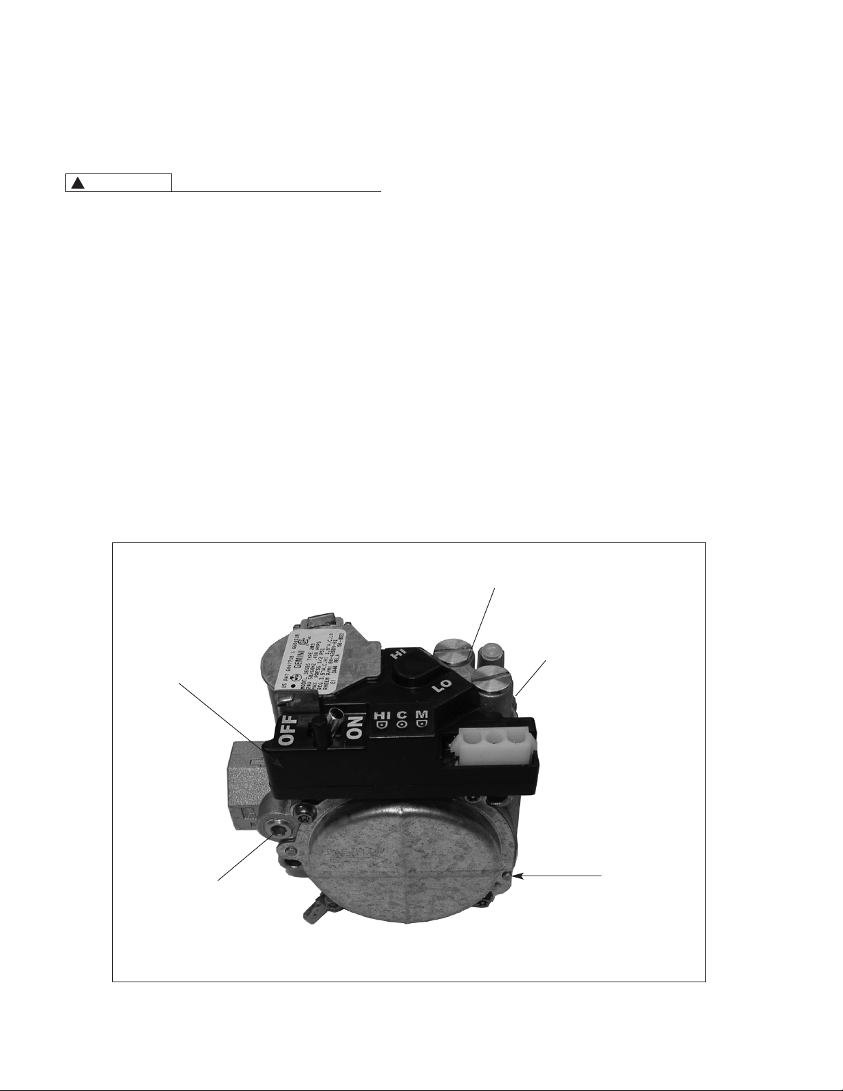
for making pressure adjustments. See Figure 1.
COMPLETING CONVERSION
1. Using a ball point indelible pen, record the following information on the conversion label.
. Conversion kit number.
a
b. Date of conversion.
c. Installer’s name, address and telephone number.
d. Burner orifice size.
2. Place completed conversion label adjacent to the rating
plate.
3. Install the burner compartment access door.
4. Run furnace through complete cycle to check operation.
FIGURE 1
GAS VALVE WHITE-RODGERS
GAS CONTROL
SWITCH
INLET
PRESSURE
TAP
HIGH FIRE MANIFOLD
PRESSURE ADJUSTMENT
LOW FIRE MANIFOLD
PRESSURE ADJUSTMENT
OUTLET
PRESSURE
TAP
2
CM 0415
 Loading...