

Page 1
INSTALLATION INSTRUCTIONS
DO NOT DESTROY THIS MANUAL. PLEASE READ CAREFULLY AND KEEP
IN A SAFE PLACE FOR FUTURE REFERENCE BY QUALIFIED SERVICE PERSONNEL.
ISO 9001:2008
HYDRONIC AIR HANDLER
RWIT-
SUPERSEDES 92-24161-150-00
92-24161-150-01
Page 2
SAFETY INFORMATION
WARNING
!
WHEN AN AIR HANDLER IS
INSTALLED SO THAT SUPPLY
DUCTS CARRY AIR CIRCULATED
BY THE AIR HANDLER TO AREAS
OUTSIDE THE SPACE
CONTAINING THE AIR HANDLER,
THE RETURN AIR SHALL ALSO
BE HANDLED BY DUCT(S)
SEALED TO THE AIR HANDLER
CASING AND TERMINATING
OUTSIDE THE SPACE
CONTAINING THE AIR HANDLER.
WARNING
!
INSTALLATION MUST COMPLY
WITH ALL INSTALLATION
INSTRUCTIONS INCLUDING:
• AIR HANDLER OPERATING
UNDER THERMOSTATIC
CONTROL;
• RETURN AIR DUCT SEALED TO
THE AIR HANDLER;
• AIR FILTERS IN PLACE;
• RETURN AIR TEMPERATURE
MAINTAINED BETWEEN 55°F
(13°C) AND 80°F (27°C); AND
• CLEAN AIR HANDLER, DUCT
WORK AND COMPONENTS
UPON SUBSTANTIAL
COMPLETION OF THE
CONSTRUCTION PROCESS,
AND VERIFY AIR HANDLER
OPERATING CONDITIONS
INCLUDING FLOW RATE AND
TEMPERATURE RISE,
ACCORDING TO THE
INSTRUCTIONS.
NOTICE
IMPROPER INSTALLATION, OR
INSTALLATION NOT MADE IN
ACCORDANCE WITH THE
UNDERWRITERS LABORATORY
(UL) CERTIFICATION OR THESE
INSTRUCTIONS, CAN RESULT IN
UNSATISFACTORY OPERATION
AND/OR DANGEROUS CONDITIONS AND ARE NOT COVERED
BY THE UNIT WARRANTY.
WARNING
!
DUCT LEAKS CAN CREATE AN
UNBALANCED SYSTEM AND
DRAW POLLUTANTS SUCH AS
DIRT, DUST, FUMES AND ODORS
INTO THE HOME CAUSING
PROPERTY DAMAGE. FUMES
AND ODORS FROM TOXIC,
VOLATILE OR FLAMMABLE
CHEM I CALS, AS WELL AS AUTOMOBILE EXHAUST AND CARBON
MONOXIDE (CO), CAN BE DRAWN
INTO THE LIVING SPACE
THROUGH LEAKING DUCTS AND
UNBALANCED DUCT SYSTEMS
CAUSING PERSONAL INJURY OR
DEATH (SEE FIGURE 2).
• IF AIR-MOVING EQUIPMENT OR
DUCTWORK IS LOCATED IN
GARAGES OR OFF-GARAGE
STORAGE AREAS - ALL JOINTS,
SEAMS, AND OPENINGS IN THE
EQUIPMENT AND DUCT MUST
BE SEALED TO LIMIT THE
MIGRATION OF TOXIC FUMES
AND ODORS INCLUDING CAR BON MONOXIDE FROM
MIGRATING INTO THE LIVING
SPACE.
• IF AIR-MOVING EQUIPMENT OR
DUCTWORK IS LOCATED IN
SPACES CONTAINING FUEL
BURNING APPLIANCES SUCH
AS WATER HEATERS OR
BOILERS - ALL JOINTS, SEAMS,
AND OPENINGS IN THE EQUIP MENT AND DUCT MUST ALSO
BE SEALED TO PREVENT
DEPRESSURIZATION OF THE
SPACE AND POSSIBLE
MIGRATION OF COMBUSTION
BYPRODUCTS INCLUDING
CARBON MONOXIDE INTO THE
LIVING SPACE.
NOTICE
APPLICATION OF THIS HYDRONIC
AIR HANDLER SHOULD BE
INDOORS. SPECIAL ATTENTION
SHOULD BE GIVEN TO UNIT
SIZING AND PIPING, FILLING, AND
PURGING.
CAUTION
FAILURE TO FOLLOW THIS
CAUTION MAY RESULT IN
PERSONAL INJURY. SHEET
METAL PARTS MAY HAVE
SHARP EDGES OR BURRS. USE
CARE AND WEAR APPROPRIATE
PROTECTIVE CLOTHING.
CAUTION
!
WHEN USED IN COOLING
APPLICATIONS, EXCESSIVE
SWEATING MAY OCCUR WHEN
UNIT IS INSTALLED IN AN
UNCONDITIONED SPACE. THIS
CAN RESULT IN PROPERTY
DAMAGE.
NOTICE
IN COMPLIANCE WITH
RECOGNIZED CODES, IT IS
RECOMMENDED THAT AN
AUXILIARY DRAIN PAN BE
INSTALLED UNDER ALL
EVAPORATOR COILS AND UNITS
CONTAINING EVAPORATOR
COILS AND AIR HANDLERS USED
WITH EVAPORATOR COILS THAT
ARE LOCATED IN ANY AREA OF A
STRUCTURE WHERE DAMAGE TO
THE BUILDING OR BUILDING
CONTENTS MAY OCCUR AS A
RESULT OF AN OVERFLOW OF
THE COIL DRAIN PAN, A
STOPPAGE IN THE PRIMARY
CONDENSATE DRAIN PIPING OR
ANY WATER LEAK POTENTIAL
FROM THE AIR HANDLER.
WARNING
!
DO NOT OPERATE THE SYSTEM
WITHOUT FILTERS. A PORTION
OF THE DUST ENTRAINED IN THE
AIR MAY TEMPORARILY LODGE
IN THE DUCT RUNS AND AT THE
SUPPLY REGISTERS. THIS
RESIDUE COULD SOIL CEILINGS,
WALLS, DRAPES, CARPETS AND
OTHER ARTICLES IN THE HOUSE.
SOOT DAMAGE MAY OCCUR
WITH FILTERS IN PLACE, WHEN
CERTAIN TYPES OF CANDLES,
OIL LAMPS OR STANDING PILOTS
ARE BURNED.
CAUTION
!
HORIZONTAL UNITS MUST BE
CONFIGURED FOR RIGHT HAND
AIR SUPPLY OR LEFT HAND AIR
SUPPLY. HORIZONTAL DRAIN
PAN MUST BE LOCATED UNDER
INDOOR COIL. FAILURE TO USE
THE DRAIN PAN CAN RESULT IN
PROPERTY DAMAGE.
NOTICE
!
CODES AND STANDARDS:
IT IS THE RESPONSIBILITY OF
THE INSTALLER TO FOLLOW ALL
NATIONAL CODES, STANDARDS
AND LOCAL ORDINANCES, IN
ADDITION TO INSTRUCTIONS
LAID OUT IN THIS MANUAL. THE
INSTALLATION MUST COMPLY
WITH REGULATIONS OF THE
LOCAL BUILDING, HEATING,
PLUMBING, AND OTHER CODES.
WHERE LOCAL CODES ARE NOT
APPLICABLE, THE INSTALLATION
MUST COMPLY WITH THE
NATIONAL CODES AND ANY AND
ALL AUTHORITIES HAVING
JURISDICTION.
2
Page 3

WARNING
!
IMPORTANT: All manufacturer
products meet current Federal OSHA
Guidelines for safety. California
Proposition 65 warnings are required
for certain products, which are not
covered by the OSHA standards.
California's Proposition 65 requires
warnings for products sold in California
that contain, or produce, any of over
600 listed chemicals known to the State
of California to cause cancer or birth
defects such as fiberglass insulation,
lead in brass, and combustion products
from natural gas.
All “new equipment” shipped for sale in
California will have labels stating that
the product contains and/or produces
Proposition 65 chemicals. Although we
have not changed our processes,
having the same label on all our
products facilitates manufacturing and
shipping. We cannot always know
“when, or if” products will be sold in the
California market.
You may receive inquiries from
customers about chemicals found in, or
produced by, some of our heating and
air-conditioning equipment, or found in
natural gas used with some of our
products. Listed below are those
chemicals and substances commonly
associated with similar equipment in
our industry and other manufacturers.
• Glass Wool (Fiberglass) Insulation
• Carbon Monoxide (CO)
• Formaldehyde
• Benzene
More details are available at the
Websites for OSHA (Occupational
Safety and Health Administration), at
www.osha.gov
California's OEHHA (Office of
Environmental Health Hazard
Assessment), at www.oehha.org.
Consumer education is important since
the chemicals and substances on the
list are found in our daily lives. Most
consumers are aware that products
present safety and health risks, when
improperly used, handled and
maintained.
and the State of
CONTENTS
Safety Precautions...................................................................................................1
Safety Information....................................................................................................2
General Information..................................................................................................4
Location Requirements and Considerations............................................................6
Selection Procedure.................................................................................................8
Ducting...................................................................................................................10
Installation..............................................................................................................12
Plumbing.................................................................................................................13
Electrical Wiring......................................................................................................16
Accessories............................................................................................................16
Sequence of Operation..........................................................................................20
Maintenance...........................................................................................................22
Troubleshooting......................................................................................................24
Wiring Diagrams................................................................................................25-26
PROHIBITED APPLICATIONS
RWI(-) HYDRONIC AIR HANDLERS ARE EQUIPPED STANDARD WITH
STAINLESS STEEL PUMPS AND COMPLY WITH CALIFORNIA PER AB1953
AND VERMONT PER SB152 FOR USE IN AIR HANDLER AND IN AN OPEN
SYSTEM WITH POTABLE WATER.
IMPORTANT: TO ENSURE PROPER INSTALLATION AND OPERATION OF
THIS PRODUCT, COMPLETELY READ ALL INSTRUCTIONS PRIOR TO
ATTEMPTING TO ASSEMBLE, INSTALL, OPERATE, MAINTAIN OR REPAIR
THIS PRODUCT. UPON UNPACKING OF THE AIR HANDLER, INSPECT ALL
PARTS FOR DAMAGE PRIOR TO INSTALLATION AND START-UP.
3
Page 4
GENERAL INFORMATION
11
8
9
10
6
4
7
5
1
2
3
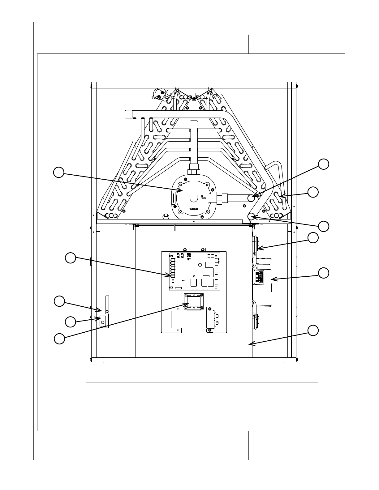
FIGURE 1
THE RWI(-) SERIES HYDRONIC AIR HANDLERS ARE DESIGN-CERTIFIED BY UL
ITEM ITEM
NO. PART NAME NO. PART NAME
1 DOOR SWITCH 7 PUMP
2 JUNCTION BOX 8 WATER INLET (OUTLET FOR 14” HAH)
3 TRANSFORMERS 9 WATER OUTLET (INLET FOR 14” HAH)
4 CAPACITORS 10 BLOWER MOTOR
5 LOW VOLTAGE (THERMOSTAT) TERMINAL 11 HYDRONIC COIL ASSEMBLY
6 BLOWER
ST-A1242-01-X0
4
Page 5
IMPORTANT
INFORMATION ABOUT
EFFICIENCY AND INDOOR
AIR QUALITY
Central cooling and heating
equipment is only as efficient as the
duct system that carries the cooled or
heated air. To maintain efficiency,
comfort and good indoor air quality, it
is important to have the proper
balance between the air being
supplied to each room and the air
returning to the cooling and heating
equipment.
Proper balance and sealing of the
duct system improves the efficiency
of the heating and air conditioning
system and improves the indoor air
quality of the home by reducing the
amount of airborne pollutants that
enter homes from spaces where the
ductwork and/or equipment is
located. The manufacturer and the
U.S. Environmental Protection
Agency’s ENERGY STAR Program
recommend that central duct systems
be checked by a qualified contractor
for proper balance and sealing.
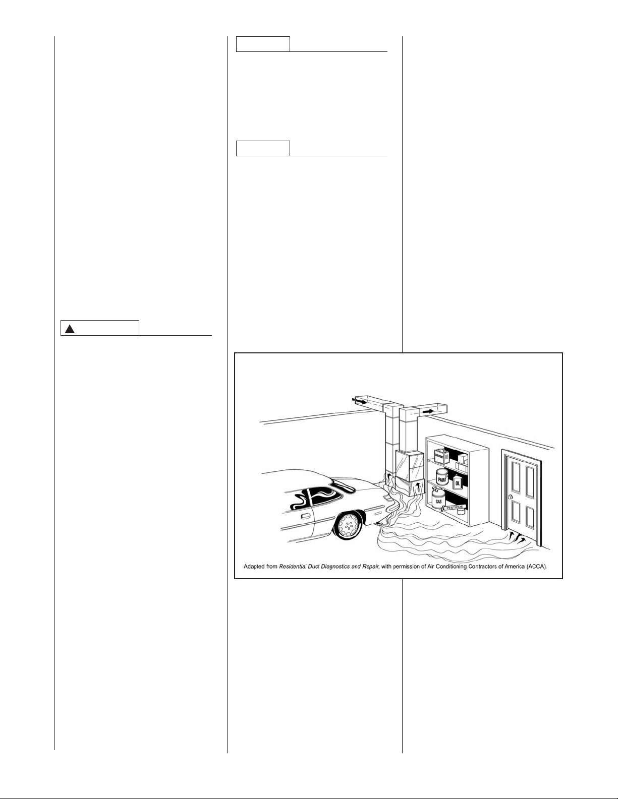
WARNING
!
DUCT LEAKS CAN CREATE AN
UNBALANCED SYSTEM AND
DRAW POLLUTANTS SUCH AS
DIRT, DUST, FUMES AND ODORS
INTO THE HOME CAUSING
PROPERTY DAMAGE. FUMES
AND ODORS FROM TOXIC,
VOLATILE OR FLAMMABLE
CHEMICALS, AS WELL AS
AUTOMOBILE EXHAUST AND
CARBON MONOXIDE (CO), CAN
BE DRAWN INTO THE LIVING
SPACE THROUGH LEAKING
DUCTS AND UNBALANCED DUCT
SYSTEMS CAUSING PERSONAL
INJURY OR DEATH (SEE FIGURE
2).
• IF AIR-MOVING EQUIPMENT OR
DUCTWORK IS LOCATED IN
GARAGES OR OFF-GARAGE
STORAGE AREAS - ALL JOINTS,
SEAMS, AND OPENINGS IN THE
EQUIPMENT AND DUCT MUST
BE SEALED TO LIMIT THE
MIGRATION OF TOXIC FUMES
AND ODORS INCLUDING
CARBON MONOXIDE FROM
MIGRATING INTO THE LIVING
SPACE.
• IF AIR-MOVING EQUIPMENT OR
DUCTWORK IS LOCATED IN
SPACES CONTAINING FUEL
BURNING APPLIANCES SUCH
AS WATER HEATERS OR
BOILERS - ALL JOINTS, SEAMS,
AND OPENINGS IN THE
EQUIPMENT AND DUCT MUST
ALSO BE SEALED TO PREVENT
DEPRESSURIZATION OF THE
SPACE AND POSSIBLE
MIGRATION OF COMBUSTION
BYPRODUCTS INCLUDING
CARBON MONOXIDE INTO THE
LIVING SPACE.
NOTICE
IMPROPER INSTALLATION, OR
INSTALLATION NOT MADE IN
ACCORDANCE WITH THE UL
CERTIFICATION OR THESE
INSTRUCTIONS, CAN RESULT IN
UNSATISFACTORY OPERATION
AND/OR DANGEROUS CONDITIONS AND ARE NOT COVERED BY
THE UNIT WARRANTY.
NOTICE
IN COMPLIANCE WITH
RECOGNIZED CODES, IT IS
RECOMMENDED THAT AN
AUXILIARY DRAIN PAN BE
INSTALLED UNDER ALL
EVAPORATOR COILS OR UNITS
CONTAINING EVAPORATOR COILS
OR AIR HANDLERS USED WITH
EVAPORATOR COILS THAT ARE
LOCATED IN ANY AREA OF A
STRUCTURE DAMAGE TO THE
BUILDING OR BUILDING CONTENTS
MAY OCCUR AS A RESULT OF AN
OVERFLOW OF THE COIL DRAIN
PAN OR A STOPPAGE IN THE
PRIMARY CONDENSATE DRAIN
PIPING.
FIGURE 2
MIGRATION OF DANGEROUS SUBSTANCES, FUMES, AND ODORS INTO LIVING SPACES
RECEIVING
Immediately upon receipt, all cartons
and contents should be inspected for
transit damage. Units with damaged
cartons should be opened
immediately. If damage is found, it
should be noted on the delivery
papers, and a damage claim filed
with the last carrier.
• After unit has been delivered to job
site, remove carton, taking care
not to damage unit.
• Check the unit rating plate for unit
size, voltage, phase, etc. to be
sure equipment matches what is
required for the job specification.
• Read the entire instructions before
starting the installation.
• Some building codes require extra
cabinet insulation and gasketing
when unit is installed in attic
applications.
• If installed in an unconditioned
space, apply caulking around the
power wires, control wires,
refrigerant tubing and condensate
line where they enter the cabinet.
Seal the power wires on the inside
where they exit conduit opening.
Caulking is required to prevent air
leakage into and condensate from
forming inside the unit, control box,
and on electrical controls.
• Install the unit in such a way as to
allow necessary access to the
coil/pump and blower/control
compartment.
• Install the unit in a level position to
ensure proper condensate
drainage. Make sure unit is level in
both directions within 1/8”.
• Install the unit in accordance with
any local code which may apply
and the national codes. Latest
editions are available from:
“National Fire Protection
Association, Inc., Batterymarch
Park, Quincy, MA 02269.” These
publications are:
• ANSI/NFPA No. 70-(Latest Edition)
National Electrical Code.
• NFPA90A Installation of Air
Conditioning and Ventilating
Systems.
• NFPA90B Installation of Warm Air
Heating and Air Conditioning
Systems.
• The equipment has been
evaluated in accordance with the
Code of Federal Regulations,
Chapter XX, Part 3280.
5
Page 6
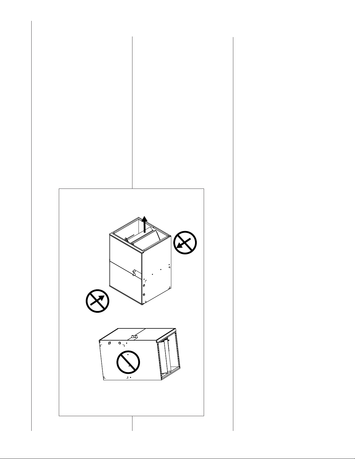
LOCATION REQUIREMENTS AND CONSIDERATIONS
FRONT
BACK
THE AIR INLET IS NOT ALLOWED TO BE AT THE FRONT
OR BACK OF THE AIR HANDLER.
DO NOT POSITION THE AIR HANDLER ON ITS BACK OR
WITH IT FACE DOWN. DO NOT CUT SIDES OF
HORIZONTAL APPLICATION.
PROHIBITED INSTALLATIONS
NOTE: MULTIPLE AIR
HANDLERS CONFIGURED
FOR INSTALLATION WITH A
SINGLE TANKLESS WATER IS
PROHIBITED.
ST-A1242-02-X0
GENERAL INFORMATION
1. IMPORTANT: If installing the unit
over a finished ceiling or living
area, be certain to install an
auxiliary condensate drain pan
under the entire unit. This
auxiliary drain pan should extend
under any evaporator coil
installed with the air handler and
the open portion of the
condensate drain assembly.
2. IMPORTANT: If using a cooling
evaporator coil with this air
handler:
Be sure the air passes over the
coil/pump before passing over
the cooling coil.
FIGURE 3
IMPORTANT: Support this unit
when installed. Since this air
handler is suitable for attic or
crawl space installations, it may
be installed on combustible wood
flooring or by using support
brackets. See Figure 5.
5. IMPORTANT: If installing in a
utility room, be sure the door
is wide enough to:
a. allow the largest part of the air
handler to pass; or
b. allow any other appliance
(such as a water heater)
to pass.
6. IMPORTANT: This air handler is
not approved or recommended
for installation on its back, with
access doors facing upwards
(see Figure 3).
CLEARANCE ACCESSIBILITY
The design of air handlers with input
ratings as listed in the tables under
Figure 4 are certified by UL for the
clearances to combustible materials
shown in inches.
See name/rating plate and clearance
label for specific model number and
clearance information.
Service clearance of at least 24” is
recommended in front of
all air handlers.
NOTE: Use recommended 24”
clearance if accessibility clearances
are greater than fire protection
clearances.
Air handlers are shipped with a
bottom closure panel installed.
When bottom return air is used,
remove the panel by removing the
two screws attaching the panel to
the front base angle.
SITE SELECTION
1. Select a site in the building near
the center of the proposed, or
existing, duct system.
2. Locate the air handler to maintain
proper clearance to combustibles
as shown in the following tables.
6
ST-A1242-02-X0
Page 7
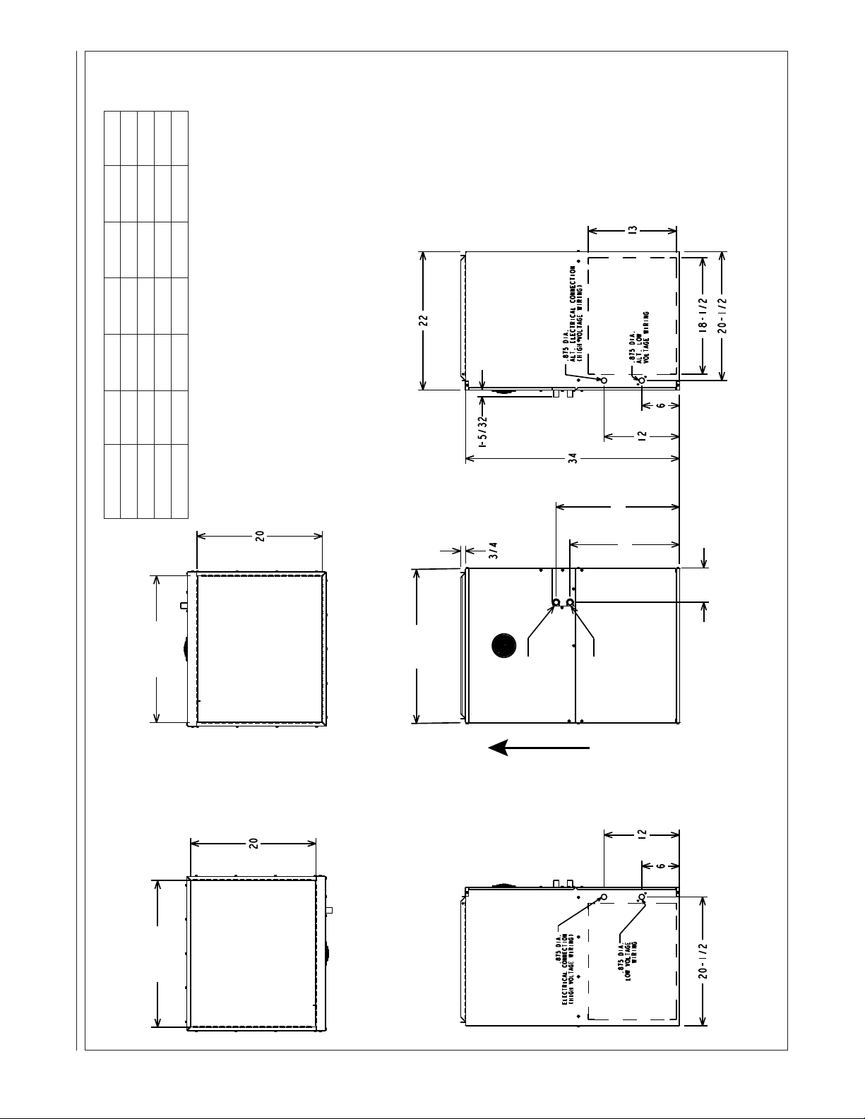
FIGURE 4
RETURN AIRSUPPLY AIR
TOP
BOTTOM
LEFT
RIGHT
FRONT
OPTIONAL RETURN AIR CUTOUT
(EITHER SIDE)
OPTIONAL RETURN AIR CUTOUT
(EITHER SIDE)
A
I
R
F
L
O
W
A
B
C
REF
D
E
F
G
H
CLEARANCE TO COMBUSTIBLES, UPFLOW, HORIZONTAL LEFT OR RIGHT, DOWNFLOW
⁄8
⁄8
⁄16
3
⁄16 19 3
13
⁄16
5
7
7
⁄8 5
5
⁄16 19 4
⁄16 19 4
⁄16 19
7
13
13
⁄2 16
⁄2 17
1
1
⁄2 16
⁄2 23
1
1
⁄2 16
⁄2 23
1
1
ST-A1242-03-X0
Model A B C D E F
RW1T06A3617 17
RW1T08A4821 21 20 20 16
RW1T04A2414 14 13 13 16
RW1T10A6024 24
Note: Service clearance of 24” is recommended in front of air handler.
7
Page 8
SELECTION PROCEDURE
2
Model Number Nomenclature
(WITH EXAMPLE)
I. Define hot water load for the total
required domestic hot water
usage.
As an example, let’s assume that the
selected Tankless Water Heater for your
whole house solution is the RTG-74 and
your calculated heat gain and heat loss
values are as stated in section II.
II. Determine cooling and heating
requirements at design conditions:
The ACCA’s Manual J Residential Load
Calculation method is the established
trade standard, approved by ANSI, for
the correct siziing and selection of
Heating, Ventilation, Air-Conditioning
and Refrigeration (HVACR) equipment in
residential homes. The most recent
revision is the eight edition, an allinclusive new approach to ensuring that
Indoor Air Quality (IAQ) systems are as
efficient, safe, and healthy as possible.
Refer to the Air Conditioning Contractors
of America website at:
http://www.acca.org/tech/manualj/
qualified HVACR contractor for further
assistance.
or a
Assumptions:
Required Cooling Capacity . 48,000 BTU/HR
(Total Capacity)
Required Heating Capacity . 60,000 BTU/HR
Evaporator Air Quantity. . . . . . . . . 1600 CFM
External Static Pressure . . . . . . . 0.2 in. W.C.
Electrical Characteristics . . . . . . . . . 115-1-60
III. Determine total external static
pressure (ESP) at design
conditions:
Before using the Airflow Performance
Table calculate the total static pressure
required. From the given example, note
the Wet Coil Pressure Drop (selected
from the field supplied Evaporative
Cased Coil Installation Instructions), and
the Filter Pressure Drop. Determine both
static pressures at 1600 CFM:
Wet Coil Pressure Drop . . . .0.3 in. W.C.
(From Coil Manufacturer’s Installation Instructions)
External Static Pressure . . . 0.2 in. W.C.
(Ductwork, etc.)
Filter Pressure Drop . . . .08 in. W.C.
(.08 inches if the included filter is used; refer to
the filter’s manufacturer’s instructions if another
filter is used.)
Total Static Pressure. . . 0.58 in. W.C.
IV. Select unit based on required
cooling capacity airflow:
For an initial selection, choose a unit
size that will provide the required
airflow. Refer to Airflow Performance
Table. Note that at 0.6 ESP (external
static pressure) the
RW1T06A3617NAA unit will deliver
1560 CFM when configured for HIGH
speed.
V. Select heating capacity of unit
to provide the requisite design
condition:
From the Hydronic Air Handler/
Tankless Water Heater, note that the
unit RW1T06A3617NAA, (as selected
above) when matched with the RTG95 Tankless Water Heater, will
provide 59.2 MBH (59,200 BTU/HR)
at an input water temperature (to Air
Handler) of 150°F.
TRADE BRAND
R = RHEEM
PRODUCT CATEGORY
W = HYDRONIC AIR HANDLER
STAGE OF AIR FLOW
1 = SINGLE
2 = TWO STAGE
M = MODULATING
MOTOR TYPE
T = CONSTANT TORQUE
V = VARIABLE SPEED
P = PSC
NOMINAL CAPACITY
04 = 40,000 BTU/H
06 = 60,000 BTU/H
08 = 80,000 BTU/H
10 = 100,000 BTU/H
MAJOR SERIES
A = FIRST
8
RW 1 T 04 A 24 14 NAA***
CONTROLS
C = COMMUNICATING
N = NON-COMMUNICATING
WIDTH
14 = 14”
17 = 17.5”
21 = 21”
24 = 24.5”
MAX COOLING AIRFLOW TONNAGE
24 = UP TO 2 TON
36 = UP TO 3 TON
48 = 2.5 TO 4 TON
60 = 3 TO 5 TON
OPTION CODE (SEE ADS-3803)
BLANK = NONE
MINOR SERIES
A = FIRST
VOLTAGE
A = 115/1/60
Page 9
HYDRONIC AIR HANDLER ELECTRICAL PHYSICAL SPECIFICATIONS - ECO-TECH™ MODELS
!"#$% &
'()*&%"#$
+()*$%&
,-$$.
/0#$%1"(&
2#"#34&
-%$225%$
63%&'()*
7$"#&
8"-"43#9
:1($# ;5#($# <$(#" :1($# ;5#($# <$(#"
!"# !#$ !!
%&# !#" '! "()$!*
!'# !!( !*
*&( !#+ '( '!)*++
!*# !"" !+
*&# !!' *! '%)("+
!%# !"$ "!
'&+ !!$ *, *#)%$'
!(# !'" "+
'&' !"# %' *%)*%*
!"# $( "*
*&# !#* '(
*,)#*#
!'# !#! "$
'&+ !!# *"
%*)'##
!*# !#% '%
'&' !!" **
%,)%$+
!%# !!% '%
'&* !!* *(
%$)'*+
!(# !"! '$ '&' !!+ %# (*)'$+
!"# !## "#
*&+ $% ",
*,),((
!'# !#' ",
*&" !## '"
%%),#'
!*# !#% '%
'&( !#* '(
(")'*!
!%# !#+ *"
'&% !!# *"
,*)!*,
!(# !#( %* '&# !!* *( +#)$$,
!"# $' ",
*&( !## '"
(")'#+
!'# $+ '"
*&" !#' '%
(,)('%
!*# !#! '$
'&( !#* '(
($)$'(
!%# !#' *,
'&( !!! *'
+*)!'#
!(# !#! %$ '&' !!+ %# $,)%!*
63%&7"1.($%&=).$(
>?@=A
>%-BA
>31C&*C4CA
>8D=A
-.!/#*0
-.!/#(0
-.!/#+0
-.!/!#0
1234
#&%
!+##
(+&##
!"#$% &E$B-$%"#5%$
63%&E$B-$%"#5%$
>FDA
>FDA
(+&##
1234
#&%$
!"##
(+&##
!("%
#&%
1234
>+#5GH%A
(+&##
1234
#&%*
+##
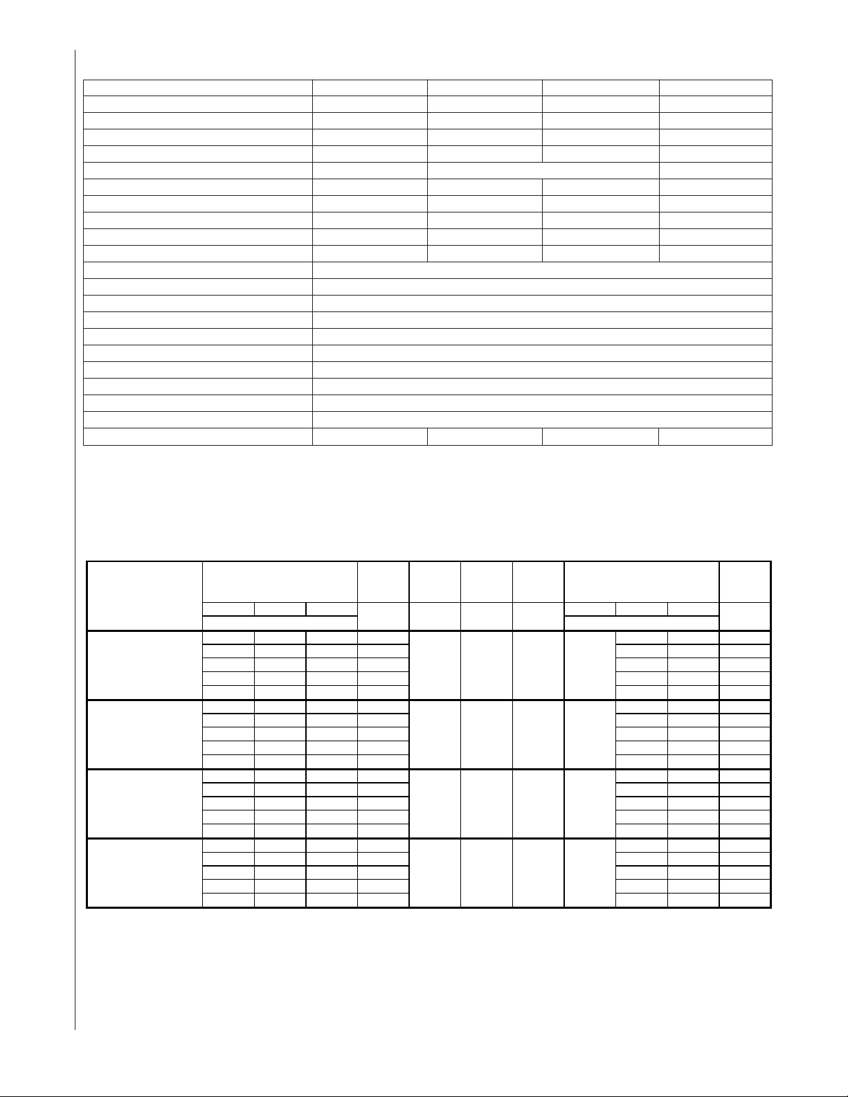
Model Numbers
RW1T04A2414NAA RW1T06A3617NAA RW1T08A4821NAA RW1T10A6024NAA
Nominal Heating Capacity BTU/hr [kw] 40000 [11.7] 60000 [17.6] 80000 [23.4] 100000 [29.3]
Air Side Temperature Rise* °F [°C] 32-53 [17.6-29.2] 24-43 [13.2-23.7] 25-49 [13.8-27.0] 25-46 [13.8-25.3]
Rated Heating CFM [L/s] 800 [378] 1200 [566] 1625 [767] 1800 [850]
Cooling Range CFM [L/s] 600-800 [283-556] 800-1200 [283-612] 1000-1625 [472-775] 1200-1800 [612-804]
Power Supply (V - HZ - PH) 115 - 60 - 1
Minimum Circuit Ampacity - Amps 8 10 12.9 12.9
Max Rating of Over Current Protective Device - Amps 11.7 18 23.2 23.2
Maximum Fuse or Circuit Breaker Size - Amps 10 15 20 20
Motor HP [W] 1/3 [248] 1/2 [373] 3/4 [559] 3/4 [559]
Blower (D x W) in [mm] 10 x 6 [254 x 152] 10 x 8 [254 x 203] 10 x 10 [254 x 254] 11 x 11 [279 x 279]
Blower Motor Type EcoTech / ECM Type
Pump Type Wet Rotor
Pump Power Supply (V - HZ - PH) 115 - 60 - 1
Pump Motor RLA/LRA - Amps 1.8
Pump HP [W] 1/8 [.86]
Pump Maximum Working Pressure psi [kPa] 125 [861]
Max Working Temperature °F [°C] 160 [71]
Water Connection Type Copper Studs
Inlet Water Connection Diameter in [mm] 3/4 [19]
Out Water Connection Diameter in [mm] 3/4 [19]
Shipping Weight LBS [kg] 91 [41] 100 [45] 122 [55] 129 [58]
HYDRONIC AIR HANDLER HEATING PERFORMANCE
9
Page 10

DUCTING
CUT OUT USING
EMBOSSED ANGLES
AS A GUIDE FOR THE
PROPER SIZE.
JACKET
Proper air flow is required for the
correct operation of this air handler.
Too little air flow can cause erratic
operation and can damage the heat
exchanger. The duct system must
carry the correct amount of air for
heating and cooling if summer air
conditioning is used.
Size the ducts according to
acceptable industry standards and
methods. The total static pressure
drop of the air distribution system
should not exceed 0.8" w.c.
NOTE: Return air grilles and warm air
registers must not be obstructed
IMPORTANT: Some high efficiency
filters have a greater than normal
resistance to air flow. This can
adversely affect air handler operation.
BE SURE TO CHECK AIR FLOW.
IMPORTANT: When using outside
air, design and adjust the system to
maintain a return air temperature
ABOVE 50° F during the heating
season.
UPFLOW UNITS
1. Position the unit to minimize long
runs of duct or runs of duct with
many turns and elbows.
2. Open the return air compartment.
a. Cut an opening in the side.
The opening should
be cut the full width of the
knockouts on the unit. See
Figure 5.
FIGURE 5
CUTOUT AND DRILL INFORMATION
UPFLOW ONLY
NOTE: Where the maximum air flow
is 1800 CFM or more, both sides or
the bottom must be used for return
air.
3. Connect the return duct or return
air cabinet to the unit. Make the
connection air tight to prevent
entraining combustion gases
from an adjacent fuel-burning
appliance.
4. Be sure to have adequate
space for the unit filter.
NOTE: DO NOT take return air
from bathrooms, kitchens, air
handler rooms, garages, utility or
laundry rooms, or cold areas.
NOTE: DO NOT use a rear air
return.
5. If summer air conditioning (heat
pump) is desired, position the
indoor coil on the top of the unit.
Insure that no air can bypass this
coil.
6. Connect the supply air plenum to
the air handler plenum opening.
HORIZONTAL UNIT
1. Position the unit to minimize long
runs or runs with many turns and
elbows.
2. If summer air conditioning or heat
pump is desired, position the
indoor coil on the supply air end
of the unit. Insure that no air can
bypass this coil.
3. Connect the air handler to the
supply air plenum.
4. Connect the return air ducting to
the return air opening of the unit.
Make the connection air tight to
prevent pulling combustion gases
from an adjacent fuel-burning
appliance.
5. Be sure to have adequate
space for the unit filter.
NOTE: DO NOT take return air
from bathrooms, kitchens, air
handler rooms, garages, utility or
laundry rooms, or cold areas.
DOWNFLOW UNITS
1. Position the unit to minimize long
runs of duct or runs of duct with
many turns and elbows.
2. If summer air conditioning is
desired, position the indoor coil
on the supply air side of the unit.
Insure that no air can bypass this
coil.
3. Connect the furnace to the
supply air plenum.
4. Connect the return air ducting to
the return air opening at the top
of the unit. Make the connection
air tight to prevent entraining
combustion gases from an
adjacent fuel-burning appliance.
5. Be sure to have adequate space
for the unit filter.
NOTE: DO NOT take return air
from bathrooms, kitchens,
furnace rooms, garages, utility or
laundry rooms, or cold areas.
*Solid metal bottom required if side duct penetration is used.
10
ST-A1242-04-X0
Page 11

FIGURE 6
POSITION ORIENTATION
ST-A1242-05-X0
11
Page 12

INSTALLATION
Refer to the specification section of this
d
DOOR
ASSEMBLY
8” MIN FOR
DOOR REMOVAL
(2) HEX NUTS, (2) WASHERS & (2)
LOCK WASHERS REQ. PER ROD
USE 1” SQUARE, 1-1/4 x 1-1/4 x 1/4
ANGLE IRON OR EQUIVALENT
SECURE ANGLE
IRON TO BOTTOM
OF AIR HANDLER
WITH 3 #8 x 3/4”
SCREWS TYPCIAL
FOR 2 SUPPORTS
1/4” THREADED ROD
(4 REQUIRED)
F
DOORS
1 INCH x 22 GAUGE
GALVANIZED STRAPS
TYPICAL FOR 4 STRAPS
RETURN AIR
OPENING
SUPPLYAIR OPENING
BACK
SUSPENDED CABINET
INSTALLATION
If the cabinet cannot be supported on a
frame or supported from the wall, it may
be suspended.
Use metal strapping or threaded rod with
angle iron supports under cabinet for
support. These supports MUST run
parallel with the length of the cabinet.
Ensure that there is adequate room to
remove service and access panels after
installing supporting brackets.
If an auxiliary drain pan is required, the
support is to be placed under a drain
pan.
FIGURE 7
HORIZONTAL UNIT SUSPENSION
WARNING
!
IT IS THE INSTALLER’S
RESPONSIBILITY TO USE AN
APPROPRIATE HANGING METHOD
CAPABLE OF SUPPORTING THE
UNIT’S WEIGHT. REFER TO THE
SPECIFICATION SECTION OF THIS
DOCUMENT FOR THE RESPECTIVE
UNIT’S INSTALLED WEIGHTS.
NOTICE
FOR SEISMIC HANGING
REQUIREMENTS, REFER TO LOCAL
CODES.
Attachment Methods Using Straps
Method 1
Use (4) #8 x 3/4 sheet metal screws
for each strap. The straps should be
vertical against the air handler sides
and not pull away from the air handler
sides.
Method 2
Fold all straps under the air handler
and secure with (4) #8 x 3/4 sheet
metal screws (2 screws at the side
and 2 screws at the bottom. (Care
must be taken not to drive the screw
through the coil.)
FIGURE 8
HORIZONTAL UNIT SUSPENSION WITH STRAPS
12
Page 13

PLUMBING
Codes:
The RW1T air handler is used in potable
water systems. Therefore, it is important
to observe all local sanitary codes when
installing water lines. The water supply
mating connection to the Hydronic Air
Handler is made via the two 3/4 in. dia.
copper stubs labeled “WATER IN” and
“WATER OUT” (see Figure 1).
All associated hydronic piping MUST
comply with ICC, UPC and any other
local codes or ordinances having
jurisdiction. USE POTABLE GRADE
COPPER PIPING AND BRASS
APPURTENANCES ONLY.
Soldering Copper Tubing:
The common method of joining copper
tubing in hydronic heating systems is
soft soldering. Plumbing codes do not
allow solders containing lead to be used
for domestic water service. USE ONLY
95/5 tin/antimony solder for all piping
systems that incorporate a domestic
water supply.
NOTE: Precautions must be taken
during soldering to avoid debris or
solder from lodging in piping system.
Water Storage Tank:
When connecting directly to a water
storage tank it is necessary to ensure
the water flow rate does not become
excessive. Excessive water flow can
result in increased system noise and
potential system damage. In order to
regulate the flow it is required that an
adjustable valve be placed between the
air handler outlet and the storage tank.
Furthermore, two pressure taps will
need to be installed, the first located
between the air handler outlet and the
adjustable valve as near as possible to
the outlet, and the second on the inlet
water attached as near as possible to
the inlet. While the water pump is
engaged the adjustable valve will be
closed until the pressure difference
between the outlet and the inlet is
greater than 13.5 PSID.
Tubing Insulation:
Any tube-conveying fluid at a
temperature greater than that of the
surrounding air releases heat.
Insulate all accessible hot water lines
and associated valves with material,
such as expanded neoprene or
polyurethane 3/8-in. to 1⁄2-in. thick.
Match the pipe sleeve’s inside diameter
to the pipe’s outside diameter for a snug
fit. Place the pipe sleeve so the seam
will be face down on the pipe. Tape,
wire, or clamp insulation every foot or
two to secure it to the pipe. If taping is
desired, use acrylic tape instead of duct
tape.
Copper Tubing Support:
Copper tubing must be properly
supported to prevent sagging or
buckling. On horizontal runs with hard
temper tubing, the following maximum
support spacing is suggested:
• 1/2 in. to 3/4 in. tube: 5 feet maximum
spacing
• 1 in. to 1-1/4 in. tube: 6 feet maximum
spacing
The above suggested spacing does not
account for extra weight of piping
components such as an expansion tank,
etc. When such components are
present, the piping should be supported
immediately adjacent to the component.
On vertical runs, copper tubing should
be supported at each floor level or at a
maximum of every 10 feet.
Thermal Expansion of Piping:
In all hydronic systems, piping
undergoes temperature swings as the
system operates. This causes changes
in the length of the piping due to thermal
expansion.
If the piping is rigidly mounted, this
expansion can cause annoying popping
or squeaking sounds and, in extreme
cases, the piping can even buckle.
To counter expansion movement,
design piping circuits with sufficient
elbows, tees or expansion loops (only
used in large systems) or piping
supports that allow the tubing to expand
and contract freely.
Another alternative is to install an
expansion compensator fitting capable
of absorbing the movement.
Hydronic Resistance of
Fittings, Valves, and Other
Devices:
Before the total hydronic resistance
of a piping circuit can be found, the
individual hydronic resistances of all
fittings, valves, or other such
components must be determined.
One approach is to consider each
fitting, valve, or other device as an
equivalent length of copper tube of
the same pipe size (see Table 1).
By using the equivalent length of
piping for all components in the
circuit, the circuit can be treated as if
it were a single piece of pipe having
a length equal to the sum of the
actual pipe length, the total
equivalent lengths of all fittings,
valves, or other devices. Refer to
Figure 9 and the calculation of
equivalent lengths.
Pipe Sizing Considerations:
When selecting a pipe size for a
given flow rate, the resulting average
flow velocity should be between 2
and 4 feet per second.
At water flow velocities of
approximately 2 feet per second,
flowing water will carry air bubbles
along a vertical pipe. Average flow
velocities of 2 feet per second or
higher can draw along air bubbles in
a downward flow. At the above
stated velocities air bubbles shall be
routed to an air separator where they
can be collected and discharged from
the system. Use Taco 4900 series air
separator, Model 49-075, or
equivalent (field supplied).
Average flow velocities higher than 4
feet per second could cause flow
noise and should be avoided.
Expansion Tank:
All liquids used in hydronic heating
systems expand when heated. For
all practical purposes, liquids are
incompressible. Any container
completely filled with a liquid and
sealed from the atmosphere will
experience a rapid increase in
pressure as the liquid is heated.
To prevent this from occurring, all
closed-loop hydronic systems MUST
be equipped with an expansion tank.
Refer to expansion tank man u fac turer’s instructions for proper sizing
and installation.
Water circulation:
The hydronic air handler has a strict
in press cycle which will circulate the
water in the coil for 6 minutes per day
to prevent water stagnation.
13
Page 14

PROCEDURE FOR
COLDHOT
T
3
T1
1-1/2 FT
BV
1
1 FT
T4
EV2
COLD
WATER
SUPPLY
T
2
T5
EL7
2 FT
1-1/2 FT
TEMPERED
WATER
AS
EL
5
1 FT
EL
6
2 FT
1 FT
4 FT
EL
4
4 FT
3 FT
EL
3
IN
1/2 FT
EL
2
EL1
1 FT
OUT
AIR
HANDLER
CALCULATING THE TOTAL
EQUIVALENT LENGTH OF PIPE
Given piping assembly as shown in
Figure 9 below, what is the total
equivalent length of the system?
First determine the total straight pipe
lengths; next refer to Table 1 to
determine the equivalent straight pipe
length for each fitting shown. Add
together the equivalent lengths of piping
and fittings.
(3/4”) Tubing 24 ft.
7 (3/4”) 90 deg. Elbows 7 (1.9) = 13.3 ft.
5 (3/4”) Side Port Tees 5 (3.8) = 19.0 ft.
1 (3/4”) Taco air separator = .3 ft.
2 (3/4”) Ball Valve 2 (.2) = .4 ft.
Total Equivalent Length . . . . . = 57 ft.
FIGURE 9
EQUIVALENT LENGTH CALCULATION
NOTICE
WHERE POSSIBLE THE LENGTH OF
PIPE SHOULD NOT EXCEED 100
FEET TOTAL EQUIVALENT LENGTH.
ANY PIPING RUNNING THROUGH
UNCONDITIONED SPACE MUST BE
INSULATED TO PREVENT HEAT
LOSS, AND POSSIBLE FREEZING OF
THE LINE.
STICKERS INDICATING DIRECTION
OF FLOW (WATER IN AND WATER
OUT) ARE LABELED ON THE
OUTSIDE OF THE CABINET. DO NOT
REVERSE THESE LINES, AS THIS
WILL CAUSE THE UNIT TO
MALFUNCTION.
Piping Configuration
When employing a Tankless Water
Heater in a hydronic system, the
system is considered an open-loop
system when configured to
simultaneously deliver both domestic
hot water and space heating. By
definition, if the circuit is sealed off
from the atmosphere at all locations
(as is true for most modern hydronic
systems), it is called a closed-loop
system. If the circuit is open to the
atmosphere at any point, it is called
an open-loop system.
Rheem Tankless
Water Heater
COLD
WATER
SUPPLY
AIR
HANDLER
TEMPERED
WATER
Globe Valve 14.1 18.8 28.1 37.5 46.9 56.3
Angle Valve 6.3 8.3 12.5 16.7 20.8 25.0
Gate Valve 0.5 0.7 1.1 1.4 1.8 2.1
Table 1 – Equivalent Length of Straight Pipe for Valves and Fittings (ft)
0.375 0.5 0.75 1 1.25 1.5
Ball Valve (BV) 0.1 0.1 0.2 0.3 0.3 0.4
90 Degree Standard Elbow 0.9 1.3 1.9 2.5 3.1 3.8
45 Degree Standard Elbow 0.5 0.7 1.0 1.3 1.7 2.0
Diameter (in.)
Standard Tee with flow through run 0.6 0.8 1.3 1.7 2.1 2.5
Standard Tee with flow through branch 1.9 2.5 3.8 5.0 6.3 7.5
14
Page 15

Open-Loop System
All piping to be 3/4 inch.
(BV)
(DV)
Evaporator Coil
Air Separator
If piping is done in accordance with the
recommended schematic diagram
shown in Figure 10, the following purge
and priming procedure applies.
PURGING AND PRIMING THE
SYSTEM:
The following procedure describes how
the system may be piped to eliminate
the need for a “purge cart” to fill the
system and remove entrapped air
bubbles.
STEP 1: CLOSE the air separator
venting valve.
STEP 2: CLOSE ball valve 3 (BV
FIGURE 10
TYPICAL PIPING ARRANGEMENT FOR DIRECT SPACE HEATING AND DOMESTIC WATER SUPPLY WITH TANKLESS
3);
STEP 3: OPEN drain valve 3 (DV
which a hose MUST be connected and
draining to a sink, drain or outdoors.
STEP 4: CLOSE drain valves 1 & 2
1 and DV2) and OPEN ball valve 2
(DV
(BV
2).
STEP 5: OPEN cold water supply main
valve (ball valve 1 - BV
1). The system
will begin the prime/purge process using
the street pressure. Entrapped air
bubbles being pushed out of the system
will be evident by a slight vibration of the
discharge hose connected to drain valve
3 (DV
3). The hose will stop vibrating
when laminar flow is achieved.
3) to
STEP 6: CLOSE drain valve 3 (DV
STEP 7: OPEN ball valve 3 (BV
The system is now purged, primed
and ready to go.
STEP 8: OPEN the air separator
venting valve.
NOTE: For an open-loop system, use
expansion tank approved for potable
water use only.
3);
3).
15
Page 16

ELECTRICAL WIRING
WARNING
!
TURN OFF ELECTRIC POWER AT
FUSE BOX OR SERVICE PANEL
BEFORE MAKING ANY
ELECTRICAL CONNECTIONS.
FAILURE TO DO SO CAN CAUSE
ELECTRICAL SHOCK RESULTING
IN PERSONAL INJURY OR DEATH.
WARNING
!
THE CABINET MUST HAVE AN
UNINTERRUPTED GROUND
ACCORDING TO THE LATEST
EDITION OF THE NATIONAL
ELECTRICAL CODE (NEC), ANSI/
NFPA70- OR IN CANADA, THE
CANADIAN ELECTRICAL CODE,
CSA-C221 OR LOCAL CODES
THAT APPLY. DO NOT USE GAS
PIPING AS AN ELECTRICAL
GROUND. A GROUND SCREW IS
PROVIDED IN THE JUNCTION
BOX. FAILURE TO DO SO CAN
CAUSE ELECTRICAL SHOCK,
RESULTING IN PERSONAL
INJURY OR DEATH.
WARNING
!
THIS AIR HANDLER IS EQUIPPED
WITH A BLOWER DOOR SAFETY
SWITCH. DO NOT DISABLE THIS
SWITCH. FAILURE TO FOLLOW
THIS WARNING CAN RESULT IN
ELECTRICAL SHOCK, PERSONAL
INJURY OR DEATH.
IMPORTANT: The air handler must
be installed so that the electrical
components are protected from water
(condensate).
Before proceeding with the electrical
connections, be certain that the
voltage, frequency and phase
corresponds to that specified on the
air handler rating plate. For single air
handler application, maximum overcurrent protection is 15 amperes.
CAUTION
!
IF A DISCONNECT SWITCH IS TO
BE MOUNTED ON THE UNIT,
SELECT A LOCATION WHERE A
DRILL OR FASTENER WILL NOT
CONTACT ELECTRICAL OR
HYDRONIC COMPONENTS.
ELECTRICAL SHOCK CAN CAUSE
PERSONAL INJURY OR DEATH.
NOTE: Prior to making any electrical
connections, ensure that supply
voltage, frequency, and phase are as
specified on unit rating plate.
Check to ensure that the existing
electrical service is adequate to
handle the additional load imposed by
the Hydronic Air Handler. Refer to
unit wiring diagram for proper
electrical connections.
All electrical connections MUST
comply with NEC and any other local
codes or ordinances having
jurisdiction. USE COPPER WIRE
ONLY. Provide separate branch electric
circuit with field supplied disconnect
switch.
Location of disconnect switch to be in
clear site, accessible and in close
proximity to the unit.
Correct polarity MUST be maintained for
115 V wiring. If polarity is incorrect, unit
will NOT operate.
Use a separate fused branch electrical
circuit containing a properly sized fuse
or circuit breaker. Run this circuit directly
from the main switch box to an electrical
disconnect that is readily accessible and
located near the air handler. Connect
from the electrical disconnect to the
junction box on the left side of the air
handler, inside the blower compartment.
For the proper connection, refer to the
appropriate wiring diagram located on
the inside cover of the air handler
control box and in these instructions.
The electrical junction box may be
moved to the right side if necessary. A
knockout is provided. Seal the opposite
hole with plug provided.
Make all electrical connections in
accordance with the latest edition of the
National Electrical Code, ANSI/NFPA70
and local codes having jurisdiction.
These may be obtained from:
National Fire Protection
Association, Inc.
Batterymarch Park
Quincy, MA 02269
CSA - International
178 Rexdale Blvd.
Etobicoke (Toronto), Ontario
Canada M9W, 1R3
THERMOSTAT
The room thermostat must be compatible with the integrated air handler
control on the air handler. Generally,
all thermostats that are not of the
“current robbing” type are compatible
with the integrated air handler control.
The low voltage wiring should be
sized as shown (see Figures 12 and
13).
NOTE: Do not use 24 volt control
wiring smaller than No. 18 AWG.
Install the room thermostat in
accordance with the instruction sheet
packed in the box with the thermostat.
Run the thermostat lead wires inside
the blower compartment and connect
to low voltage terminals as shown on
the wiring diagram. Never install the
thermostat on an outside wall or
where it will be influenced by drafts,
concealed hot or cold water pipes or
ducts, lighting fixtures, radiation from
fireplace, sun rays, lamps, televisions,
radios or air streams from registers.
Refer to instructions packed with the
thermostat for “heater” selection or
adjustment.
ACCESSORIES
FIELD-INSTALLED
OPTION ACCESSORIES
ELECTRONIC AIR CLEANER
Line voltage power can be supplied
from the screw terminal “EAC” and a
line voltage neutral screw terminal on
the control board. This will power the
electronic air cleaner whenever the
circulating air blower is in operation.
Expansion Tank:
Expansion tank for closed systems
air separator – TACO Model 49-075.
16
Page 17

FIGURE 11
W
G
R C
Y1
Y1
Y2
W
G
B
R
C
P3
FS
BLK
WHT
AIR HANDLER
Flow Sensor
(Packaged with Unit)
5 Wire
3 Wire Heating Only
Single Stage
Thermostat
24Volt FS / WH Connector
24 VoltTerminal Block
Control Box
PCB
Condensing Unit
Field115, 208 / 230Volt Wiring
Field 24 Volt Wiring
Factory 24 Volt Wiring
Factory115Volt Wiring
Junction Box
L1
L2
FIRST STAGE HEAT/COOL
AUX HEATING
FAN
24VAC HOT
24 VAC COMMON
SINGLE STAGE
AIR-HA NDLER
SINGLE SPEED
CONDENSING
UNIT
HEAT/COOL & COOL ONLY
THERMOSTATS
Y1
W
G
R
C
Y1
Y2
W
G
B
R
C
Y1
C
FIRST STAGE HEAT/COOL
AUX HEATING
FAN
RVS HEATING
24VAC HOT
24 VAC COMMON
HEAT PUMP THERMOSTATS
SINGLE STAGE
AIR-HANDLER
SINGLE STAGE
HEAT PUMP
Y1
W
G
B
R
C
Y1
W
G
B
R
C
Y1
B
R
C
Y2
FIELD WIRING DIAGRAM
FIGURE 12
THERMOSTAT WIRING DIAGRAMS
SINGLE STAGE AIR HANDLER W/SINGLE STAGE A/C
FIGURE 13
THERMOSTAT WIRING DIAGRAMS
SINGLE STAGE AIR HANDLER W/SINGLE STAGE HEAT PUMP*
*Requires Fossil Fuel Kit
Refer to Kit for further wiring instructions.
17
Page 18

System Low Voltage Wiring
Diagrams
NOTE: Local codes may require
thermostat wiring to be routed through
conduit or raceways. In such instances
splices can be made inside the Hydronic
Air Handler. All wiring must be NEC Class
I and must be separated from incoming
power leads.
Provide field-supplied disconnect for
maximum fuse or circuit breaker sizes, as
required by code.
Transformer is factory wired for 115V
operation.
The secondary circuit of the transformer
is protected by a 3-amp fuse mounted on
the printed circuit board.
FIGURE 14
HYDRONIC AIR-HANDLER CONTROL BOARD
Dip Switch Options:
Refer to the appropriate diagram for the
proper dip switch setting to be used with
the designed application (Figure 17).
THERMOSTAT INSTALLATION:
Thermostat should be mounted:
• approximately 5 ft. (1.5 m) from floor
TABLE 2
Wire Gauge Maximum Distance (feet)
18 gauge 60
16 gauge 100
14 gauge 160
12 gauge 250
• close to or in a frequently used
room, preferably on an inside,
partitioning wall
• on a section of wall without pipes
or duct work.
Thermostat should NOT be mounted:
• close to a window, on an outside
wall, or next to a door leading to
the outside.
NOTES:
1. For proper operation of an open loop system (refer to Figures 11 and 17), the jumper (shunt) position on PCB point “P7” should be in
the FS position.
2. When changing shunt position ensure that unit power is turned off.
18
Page 19

30 SECONDS OFF
DELAY (DEFAULT)
60 SECONDS OFF
DELAY
1
O
N
2 3 41
O
N
2 3 4
90 SECONDS OFF
DELAY
120 SECONDS OFF
DELAY
1
O
N
2 3 41
O
N
2 3 4
1
O
N
Key:
Switch is in the ON position.
Switch does not affect this setting.
1
O
N
Switch is in the OFF position.
TWO-STAGEA/C
CONFIGURATION
TWO
-STAGEHP
CONFIGURATION
1
O
N
2 3 41
O
N
2 3 4
• exposed to direct light and heat from
a lamp, sun, fireplace, or other heatradiating object which may cause a
false reading.
• close to or in direct airflow from
supply registers and return-air grilles
• In areas with poor air circulation,
such as behind a door or in an alcove
Refer to thermostat wiring diagram and
thermostat installation instructions for
further details.
FIGURE 15
DIP SWITCH POSITIONS
START-UP PROCEDURE
(HEATING ONLY):
The following conditions must be met
prior to unit start-up.
Debris from soldering and/or other
installation activities can cause
equipment failure. Ensure that all
associated lines and appurtenances
are free of debris.
Check to ensure that unit is secure.
Check that blower wheel rotates freely
within the scroll housing.
Check all wiring to ensure that
connections are tight.
Check all ductwork and pipe
connections to ensure proper seal.
Check to ensure that all packaging
wraps are removed from equipment.
Ensure that front access doors are
properly installed.
Check to ensure proper connection(s)
to the appropriate blower speed tap
(Heat /Cool – High and Low). Refer to
Dry Air Delivery Table and/or the
appropriate wiring diagram(s) in this
manual.
Perform all safety and start-up checks
for Tankless Water Heater as per
manufacturer’s instructions.
Having verified all preceding checks,
the Air Handler’s Start-Up Procedure is
as follows:
STEP 1: Purge and fill system; follow
appropriate purging procedure as laid
out in this manual in section titled
“Purging and Priming the System”.
STEP 2: Turn on power supply to air
handler. Caution: blower and/or
circulator may start to operate if
thermostat is on and a call is present.
STEP 3: Turn thermostat ON and
switch system to the heating mode.
The thermostat shall be set higher than
the actual room temperature; this will
cause the circulator to energize and
initiate the heating cycle. (If the pump
does not start, or the Air Handler is not
producing heat, refer to the
Troubleshooting Section, in this
manual).
STEP 4: Program room thermostat as
desired by homeowner.
START-UP PROCEDURE
(COOLING SYSTEM)
Refer to field-supplied evaporator coil
and outdoor unit manufacturer’s
Installation Instructions for system
hook-up, start-up instructions and
refrigerant-charging method details.
TROUBLESHOOTING BLOWER
AND/OR PUMP MOTOR AND
CONTROLS
If blower and/or pump motor does
not run:
Turn OFF power and check the
following:
1. Check that door switch is in the
CLOSED position.
2. Check 3 amp fuse on Printed
Circuit Board (PCB).
3. Check for 24 VAC between COM
and 24 VAC on IAC. If no voltage
is present, check transformer.
4. Check all connections for kinks
which could cause loose
connections. Ensure connections
are secure.
5. Verify that approximately 120
VAC is present across L1 and L2.
19
Page 20

SEQUENCE OF OPERATION
COOLING
Single Stage Cooling
• When the thermostat calls for cooling
(Y), there is a 1 second delay then
the control energizes the high blower
tap (COOL_HI).
• When the thermostat ends the call for
cooling (Y), there is a 30 second
cooling off delay then the control deenergizes the high blower tap
(COOL_HI).
• A call for cooling has priority over
continuous fan.
HEATING (HYDRONIC)
• On a call for heating the pump will
start.
• After a sixty second delay the control
will look at the FS jumper if this is
jumpered the control will go into
water heating mode and ignore the
temperature sensors.
• If the air supply temperature is
greater than 85°F the control will
energize the indoor blower. If the air
temperature is less than 85°F the
control will turn off the pump and go
into a 5 minute delay.
• If the supply temperature is adequate
the main blower will then be
energized and run for 30 seconds.
• After the 30 second delay the control
will monitor the supply temperature. If
this drops the control will turn off the
pump and go into a 5 minute delay. If
the temperature is greater than the
shut off temperature the control shall
remain in heating mode.
• There must be a minimum delta of
10°F to remain in the heating mode.
• When the W call ends the pump shall
de-energize the blower shall turn off
after a blower off delay.
The FS input shall be used to allow a
way to bypass the system to allow it to
run. If this is jumpered the control will
ignore the temperature and go into a
heating cycle.
HEATING (Heat pump is the
primary source of heat)
Single Stage Heating
• The thermostat calls for heating (Y,
R, and B), there is a 1 second delay
then the control energizes the high
blower tap (COOL_HI).
• When the thermostat ends the call for
cooling (Y), there is a 30 second
cooling off delay then the control deenergizes the high blower tap
(COOL_HI).
• When the thermostat calls for
emergency heat (W), the hydronic
heating mode is activated.
BLOWER TIME DELAY (HEATING
OR COOLING)
All models are equipped with a blower
time delay (BTD) in lieu of a blower relay
(BR) (see Figure 19). The blower will run
for 30 seconds after the blower time
delay (BTD) is de-energized.
DEFROST (DEFROST HEAT
CONTROL)
• For sequence of operation of defrost
controls, see outdoor heat pump
installation instructions.
• Supplemental heat during defrost can
be provided by connecting the purple
(PU) pigtail in the outdoor unit to the
W on the thermostat. This will
complete the circuit between R and W
through a set of contacts in the defrost
relay (DR) when the outdoor heat
pump is in defrost. This circuit, if
connected, will help prevent cold air
from being discharged from the indoor
unit during defrost.
• For most economical operation, if cold
air is not of concern during defrost, the
purple wire can be left disconnected.
Supplemental heat will then come on
only when called for by second stage
room thermostat.
EMERGENCY HEAT (HEATING
HEAT PUMP)
• If selector switch on thermostat is set
to the emergency heat positioin, the
heat pump will be locked out of the
heating circuit, and all heating will be
hydronic heat. Jumper should be
placed between W and E on the
thermostat sub-base so that the
electric heat control will transfer to the
first stage heat on the thermostat. This
will allow the indoor blower to cycle on
and off with the electric heat when the
fan switch is in the auto position.
ROOM THERMOSTAT
(ANTICIPATOR SETTING)
See instructions with outdoor section,
condensing unit or heat pump for
recommended room thermostats.
• The thermostat should be mounted
4 to 5 feet above the floor on an
inside wall of the living room or a
hallway that has a good air
circulation from the other rooms
being controlled by the thermostat.
It is essential that there be free air
circulation at the location of the
same average temperature as other
rooms being controlled. Movement
of air should not be obstructed by
furniture, doors, draperies, etc. The
thermostat should not be mounted
where it will be affected by drafts,
hot or cold water pipes or air ducts
in walls, radiant heat from
fireplaces, lamps, the sun, T.V. or
an outside wall. See instructions
sheet packaged with thermostat for
mounting and installation
instructions.
20
Page 21

!"# $"!%& !" % $"!'& !"( $"!)& !"* $"#!& !"' $"#%& !"+ $"#'& !") $"#)& !", $"#-& !"- $"%%
./0 +,+ $(%*& +(* $%--& ',% $%)'& '(! $%'!&
12345/0 )%( $(*#& +,, $(%'& +#) $%-#& '+) $%+,& '#% $%*%& *'- $%#)&
123 )*, $('(& +-) $(%-& +*, $(!+& '-) $%,%& '*, $%'-& *-# $%(%& **' $%#!&
12346786 -%% $*('& ,,' $*#,& ,*- $*!#& ,## $(,(& ))' $(++& )(( $(*+& +-' $(%,& +** $(!*& +*' $(!*&
9786 -*! $***& -#) $*((& ,)' $*#(& ,(, $(-'& )-- $())& )+! $('-& )#+ $((,& +)( $(#,& +%, $%-+&
./0 +*+ $(!'& ',% $%)'& '#) $%**& *(+ $%!+&
12345/0 -,* $*+*& -() $**%& ,-* $*%%& ,*+ $(--& )-, $())& )') $(')& )#! $(('&
123 #!() $*,-& --' $*)!& -'( $*'!& -#! $*%-& ,+, $*#!& ,%# $(,)& ),# $(+-& )() $(*,&
12346786 ##+# $'*,& #!%! $*,#& #!), $'!-& #!*! $*-#& --- $*)#& -+( $*'*& -%! $*(*& ,)( $*#%& )'( $(''&
9786 #(-) $+'-& #('* $+(-& #(%# $+%(& #%)- $+!*& #%(, $',*& ##-( $'+(& ##') $'*+& #!+, $'!*& -'+ $*'#&
./0 ,#' $(,'& )+' $(+#& )#' $(()& ++' $(#*& +#* $%-!& '', $%+(& '#* $%*(&
12345/0 #%,* $+!+& #%(( $',%& ##), $''+& ##%- $'((& #!)! $'!'& --- $*)#& -%) $*()& ,)+ $*#(& ,%( $(,,&
123 #*#- $+)!& #()( $+*,& #(%( $+%*& #%,% $+!'& #%%, $',!& ##,! $'')& ##%- $'((& #!'* $*-)& -,# $*+(&
12346786 #*,' $)!#& #*'% $+,'& #*#, $++-& #(,+ $+'*& #(*+ $+('& #(#( $+%!& #%)% $+!!& #%%% $'))& ##-' $'+*&
9786 #)*' $,%*& #)%% $,#(& #+-% $)--& #++* $),'& #+(! $)+-& #'-- $)''& #'++ $)(-& #'!* $)#!& #('+ $+*!&
./0 #!** $*-(& -'( $*'!& ,+) $*!-& )+) $(+%& ++) $(#'& ')- $%)(& '!# $%(+&
12345/0 #!#! $*))& -)! $*',& -(+ $**%& -!% $*%+& ,+) $*!-& ,(% $(-(& )-, $())& )++ $(+%& )%' $(*%&
123 #%*) $',-& ##,( $'',& ##%# $'%-& #!+* $'!%& --- $*)#& -(( $**!& ,+* $*!,& )-) $()+& )(' $(*)&
12346786 #,(* $,++& #)+, $,(*& #+-) $,!#& #+(- $))*& #',' $)*,& #'(- $)%+& #*), $+-,& #*%) $+)(& #()! $+*)&
9786 %!!, $-*,& #-'+ $-%(& #-!' $,--& #,** $,)!& #,!% $,'!& #)'! $,%+& #+-, $,!#& #+'' $),#& #+!* $)')&
:5/02;<=2;>/;?@A2<B2@CD;23<07E6/DE<>75E2;<7?<=5@A2
4
4
4
FG#H#!I+!%*JII
##<K<##<<<<<<<<<<<<
$%)-<K<%)-&
(L*<<$''-&
4
4
FG#H!,I*,%#JII
#!<K<#!<<<<<<<<<<<<<
$%'*<K<%'*&
(L*<<$''-&
4
4
FG#H!+I(+#)JII
#!<K<,<<<<<<<<<<
$%'*<K<%!(&
#L%<<$()(&
444
4
4
444
4
4
4
4
4
FG#H!*I%*#*JII
#!<K<+<<<<<<<<<<<<
$%'*<K<#'%&
#L(<$%*,&
4
4
!"#$%&'()*'$)!*&#+,$)*'$)-+%.)/,$-%$0*&(,)1),(!%)2,(!)0%#,+3
1/325
:5/02;<M7N2<7?<<
$BB&
1/E/;<9O<<
$G@EE&
:5/02;<M=223
(-0)4+567)*89)#:;8<:9=)),>?:9@A;)3?A?8B)/9:66C9:)'@BD:6).A?:9)(E;CF@)4G/A7
TABLE 3
DIRECT DRIVE
INSTRUCTIONS FOR
CHANGING BLOWER
SPEED
WARNING
!
DISCONNECT THE ELECTRICAL
SUPPLY TO THE AIR HANDLER
BEFORE ATTEMPTING TO
CHANGE THE BLOWER SPEED.
FAILURE TO DO SO CAN CAUSE
ELECTRICAL SHOCK RESULTING
IN PERSONAL INJURY OR DEATH.
The blower motor must be wired for
blower speeds required for normal
operation.
If additional blower speed taps are
available (leads connected to “M1” and
“M2” on the electronic control), speeds
may be changed if necessary to fit
requirements of the particular
installation. Reconnect the unused
motor leads to “M1” or “M2.” Check
motor lead color for speed designation.
Heating speeds should not be
reduced where it could cause the air
handler air temperature rise to
exceed the maximum outlet air
temperature specified for the unit.
IMPORTANT: Always check air
temperature rise after changing the
heating speed for any reason.
21
Page 22

MAINTENANCE
JACKET ASSEMBLY
SOLID BOTTOM
SCREWS (2) REQ’D
REMOVE FROM
SHIPPED LOCATION
RELOCATE FOR SIDE
RETURN
WARNING
!
THESE INSTRUCTIONS ARE
INTENDED AS AN AID TO
QUALIFIED SERVICE
PERSONNEL FOR PROPER
INSTALLATION, ADJUSTMENT
AND OPERATION OF THIS UNIT.
READ THESE INSTRUCTIONS
THOROUGHLY BEFORE
ATTEMPTING INSTALLATION
OR OPERATION. FAILURE TO
FOLLOW THESE INSTRUCTIONS
MAY RESULT IN IMPROPER
INSTALLATION, ADJUSTMENT,
SERVICE OR MAINTENANCE,
POSSIBLY RESULTING IN FIRE,
ELECTRICAL SHOCK, CARBON
MONOXIDE POISONING,
EXPLOSION, PROPERTY
DAMAGE, PERSONAL INJURY
OR DEATH.
DISCONNECT MAIN ELECTRICAL
POWER TO THE UNIT BEFORE
ATTEMPTING ANY MAINTENANCE. FAILURE TO DO SO CAN
CAUSE ELECTRICAL SHOCK
RESULTING IN PERSONAL
INJURY OR DEATH.
CAUTION
!
DO NOT OPERATE THE SYSTEM
FOR EXTENDED PERIODS
WITHOUT FILTERS.
A PORTION OF THE DUST
ENTRAINED IN THE AIR MAY
TEMPORARILY LODGE IN THE AIR
DUCT RUNS AND AT THE SUPPLY
REGISTERS. THIS RESIDUE CAN
SOIL CEILINGS, WALLS, DRAPES,
CARPETS AND OTHER
HOUSEHOLD ARTICLES.
FIGURE 16
22
NOTE: DISCARD BLOCK OFF PLATE
IF SIDE RETURN IS NOT REQUIRED.
ST-A1242-06-X0
Page 23

FIGURE 17
CUT OUT USING
EMBOSSED ANGLES
AS A GUIDE FOR THE
PROPER SIZE.
JACKET
FILTER LOCATIONS
LUBRICATION
IMPORTANT: DO NOT attempt to
lubricate the bearings on the blower
motor or the induced draft blower
motor. Addition of lubricants can
reduce the motor life and void the
warranty.
The blower motor and induced draft
blower motor are permanently
lubricated by the manufacturer and do
not require further attention.
The blower motor and induced draft
blower motor must be cleaned
periodically by a qualified installer,
service agency, or the gas supplier to
prevent the possibility of overheating
due to an accumulation of dust and
dirt on the windings or on the motor
exterior. And, as suggested
elsewhere in these instructions, the
air filters should be kept clean. Dirty
filters can restrict airflow. The motor
depends upon sufficient air flowing
across and through it to keep from
overheating.
SYSTEM OPERATION
INFORMATION
Advise The Customer
1. Keep the air filters clean. The
heating system will operate
better, more efficiently and more
economically.
ST-A1242-04-X0
2. Arrange the furniture and drapes
so that the supply air registers
and the return air grilles are
unobstructed.
3. Close doors and windows. This
will reduce the heating load on
the system.
4. Avoid excessive use of kitchen
exhaust fans.
5. Do not permit the heat generated
by television, lamps or radios to
influence the thermostat
operation.
6. Except for the mounting platform,
keep all combustible articles 3
feet from the air handler and vent
system.
7. IMPORTANT: Replace all blower
doors and compartment covers
after servicing the air handler. Do
not operate the unit without all
panels and doors securely in
place.
8. Explain proper operation of the
system with constant air
circulation.
ANNUAL INSPECTION
• The air handler should operate for
many years without excessive scale
build-up in the flue passageways.
However, it is recommended that a
qualified installer, service agency, or
the gas supplier annually inspect
ST-A1242-07-X0
the flue passageways, the vent
system and the main burners for
continued safe operation. Pay
particular attention to deterioration
from corrosion or other sources.
• IMPORTANT: It is recommended
that at the beginning and at
approximately half way through the
heating season, a visual inspection
be made of the main burner flames
for the desired flame appearance by
a qualified installer, service agency
or the gas supplier. If the flames are
distorted and/or there is evidence of
back pressure, check the vent and
inlet air system for blockage. If there
is carbon and scale in the heat
exchanger tubes, the heat
exchanger assembly should be
replaced.
REPLACEMENT PARTS
See sheet enclosed with air handler
for replacement part information.
TROUBLESHOOTING
Refer to Figure 18 for determining
cause of unit problems.
WIRING DIAGRAMS
Figure 19 are complete wiring
diagrams for the air handler and
power sources.
23
Page 24

FIGURE 18
ydemeResuaC elbissoPmotpmyS
lortnoc ta egatlov tcerroc rof kcehCnoitcennoc lacirtcele ensool ro ffo rewoP
lortnoc ta egatlov tcerroc rof kcehChgih oot tes - noitarbilac fo tuo tatsomrehT
Call for domesc hot water - air handler disabled unl call ends. Unit
is operang as designed.
Unit is operang as designed
rekaerb teser / sesuf ecalpeRrekaerb deppirt / sesuf nwolB
remrofsnart ecalperg–niriw kcehCevitcefed remrofsnarT
daol etaluclaceRretaeh retaw ro reldnah ria dezis ylreporpmI
gnittes pat deeps rotom kcehCwolf ria roodni reporpmI
Call for domesc hot water–air handler disabled unl call ends. Unit
is operang as designed.
Unit is operang as designed
Check line voltage at pump
Check wires and connectors
Check pump capacitor
Call for domesc hot water - air handler disabled unl call ends. Unit
is operang as designed.
Unit is operang as designed
Check line voltage at blower motor
Check wires and connectors
Check blower motor capacitor
General Trouble Shoong Chart
Power off or loosen electrical connecon
Pump does not run
Power off or loosen electrical connecon
Blower does not run
Warning: Disconnect all power to unit before servicing. Failure to shut off power can cause electrical shock resulng in personal injury or death.
Unit will not run
Insufficient heang
Water does not flow
Water lines are air locked
Purge air from lines
GENERAL TROUBLESHOOTING CHART
General Troubleshooting Chart
24
Page 25

FIGURE 19
NOTES
COMPONENT CODES
WIRE COLOR CODE
BK......BLACK
BR......BROWN
BL.......BLUE
G........GREEN
GY......GRAY
O........ORANGE
PR......PURPLE
R........RED
W.......WHITE
Y........YELLOW
WIRING INFORMATION
WARNING
-CABINET MUST BE PERMANENTLY GROUNDED
AND CONFORM TO I.E.C., N.E.C., C.E.C.,
NATIONAL WIRING REGULATIONS, AND LOCAL
CODES AS APPLICABLE.
REPLACEMENT WIRE
-MUST BE THE SAME SIZE AND TYPE
OF INSULATION AS ORIGINAL (105C. MIN.)
-FIELD INSTALLED
-FACTORY STANDARD
LOW VOLTAGE
-FIELD INSTALLED
-FACTORY OPTION
-FACTORY STANDARD
LINE VOLTAGE
ORIGINAL RELEASE
NO.:
ELECTRICAL WIRING DIAGRAM
MODELED
BY:
CHECKED:APPROVED:
REV:PART NO.:
DATE:
90-103346-05
6-26-15
H-1025S012
JHB
00
ELECTRICAL WIRING DIAGRAM – ECO TECH™ MODELS
25
Page 26

262728
Page 27

Page 28

CM 0915
 Loading...