

Rheem RT1000C6, RT2000C6, ST1000C6, RT5000C6, RT3000C6 Owner's Manual And Installation Instructions
...Page 1
This storage tank must be installed and serviced by a qualified person.
Please leave this guide with the householder.
Owner’s Guide
and
Installation Instructions
Commercial Carbon Steel
Indirect Storage Tank
Page 2
PATENTS
This storage tank may be protected by one or more patents or registered designs
in the name of Rheem Australia Pty Ltd.
TRADEMARKS
®
Registered trademark of Rheem Australia Pty Ltd.
TM
Trademark of Rheem Australia Pty Ltd.
Note: Every care has been taken to ensure the accuracy in preparation of this publication.
No liability can be accepted for any consequences, which may arise as a result of its publication.
WARNING: Plumber – Be Aware
The primary flow and return pipes between the storage tank(s) and the primary water heating source,
including the solar hot and solar cold pipes between the solar storage tank(s) and the solar collectors,
MUST BE of copper or metallic pipe. All compression fittings must use brass or copper olives.
The full length of the primary flow and return pipes MUST BE insulated.
The insulation must:
be of a type suitable for the application and capable of withstanding the temperature of the water
generated by the primary water heating source
The specification of the chosen insulation material should be checked with the insulation
manufacturer prior to installation as different materials may vary in temperature tolerance.
Closed cell type or equivalent insulation used between the storage tank(s) and solar collectors, if
this storage tank is part of a solar water heater installation, must be able to withstand the
temperature of the water generated by the solar collectors under stagnation conditions. Refer to
the installation instructions provided with the solar controller for full details on the insulation
requirements of the solar hot and solar cold pipes.
be at least 13 mm thick, however thicker insulation may be required to comply with the
requirements of AS/NZS 3500.4
be weatherproof and UV resistant if exposed
be fitted up to and cover the connections on both the storage tank(s) and the primary heating
source.
The insulation will reduce pipe heat losses and also assist in avoiding accidental contact with the pipe
work as high temperature water can flow from the primary heating source and the storage tank(s).
In addition, the insulation on the solar hot and solar cold pipes must also:
extend through any penetrations in the eaves, ceiling and roof
cover valves and fittings in the solar hot and solar cold pipe work
Note: Failure to observe these requirements also increases the risk of freeze damage.
The insulation is essential to assist in providing freeze protection and will offer corrosion protection to
a metal roof against water runoff over the copper pipe.
Uninsulated pipe work, including concealed in cavities and roof spaces or where it may be in contact
with a metal roof, may lead to freeze damage. The system has NO WARRANTY for freeze damage if
the solar hot and solar cold pipes are not insulated in accordance with the installation instructions.
Plumber: It is important to refer to and read in full the complete “Warning: Plumber – Be Aware” statement
commencing on page 19.
Page 3

3
CONTENTS
RESPONSIBLE OFFICER - We recommend you read pages 4 - 10.
The other pages are intended for the installer but may be of interest.
Contents ....................................................................................................................................... 3
About Your Storage Tank ........................................................................................................... 4
Regular Care ................................................................................................................................ 7
Water Supplies ............................................................................................................................. 9
Save A Service Call ................................................................................................................... 10
Installation .................................................................................................................................. 11
Insulation - Installation Instructions ........................................................................................ 14
Connections – Plumbing .......................................................................................................... 17
Multiple Installations ................................................................................................................. 20
Connections – Electrical ........................................................................................................... 22
Corrosion Inhibitor .................................................................................................................... 24
Commissioning .......................................................................................................................... 26
Draining The Storage Tank ....................................................................................................... 27
Rheem Australia Storage Tank Warranty ................................................................................ 31
Page 4
4
ABOUT YOUR STORAGE TANK
STORAGE TANK APPLICATION
This storage tank is designed for the purpose of storing water treated with a corrosion inhibitor and is not
designed for use with potable water. Its use in an application other than this may shorten its life.
MODEL TYPE
The Rheem® Commercial hot water storage tank you have chosen can be installed indoor or outdoor,
depending on the type of insulation selected. Aluminium clad insulation is suitable for indoor or outdoor
installation. PVC outer cover is suitable for indoor installation only (not available in Australia or New Zealand).
Heat transfer fluid is stored in a carbon steel cylinder and heated by an external primary heating source, or
via the two flanges that allow the fitment of auxiliary heating such as heat exchange coils (not supplied) or an
electric heating unit bundle. The temperature is controlled by the thermostat(s) on the heating source.
Automatic safety controls must be fitted to the primary heating source to provide safe and efficient operation.
CLOSED CIRCUIT
The storage tank is designed to operate at low pressure in a closed loop circuit, with the use of a heat
transfer fluid. The supply pressure must not exceed that shown on page 12.
HOW HOT SHOULD THE WATER BE?
The storage tank is designed for a maximum allowable water
temperature of 90°C, unless operated as a permanently vented
cylinder. Refer to the installation instructions supplied with the
primary heating source plant for further information on water
temperatures.
Note: AS 3498 requires that a water heater provides the means to
inhibit the growth of Legionella bacteria in potable water.
This storage tank is not designed to contain potable water. The
requirement to provide the means to inhibit the growth of Legionella
bacteria must be fulfilled by the secondary heating source. Refer to
installation instructions of the secondary heating source.
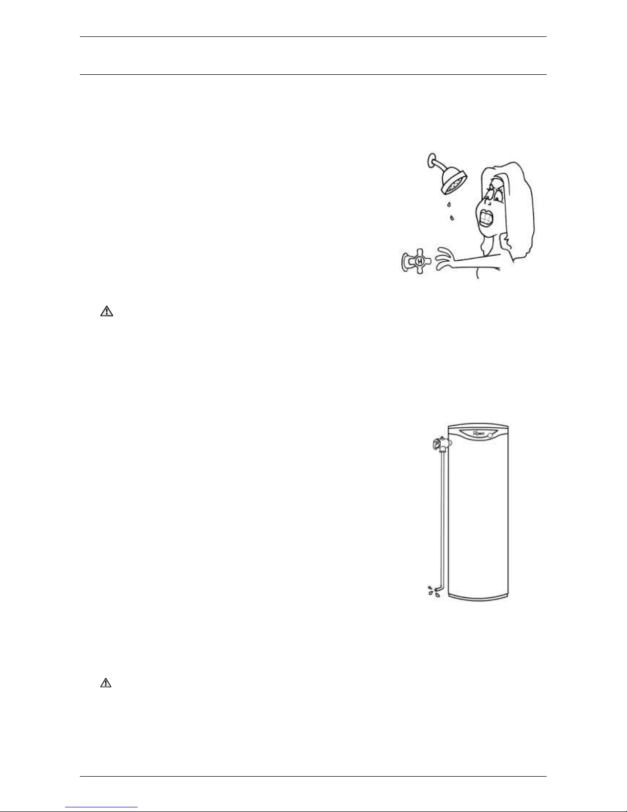
HOTTER WATER INCREASES THE RISK OF SCALD INJURY.
This storage tank can deliver water at temperatures which can
cause scalding. Check the water temperature before use, such as
when entering a shower or filling a bath or basin, to ensure it is
suitable for the application and will not cause scald injury.
We recommend and it may also be required by regulations that an approved temperature limiting device be
fitted into the hot water pipe work to the bathing and public areas when this storage tank is installed. This will
keep the water temperature below 50°C or the maximum permitted by AS/NZS 3500.4 to these areas. The
risk of scald injury will be reduced and still allow hotter water to the kitchen, laundry and other areas requiring
sanitising temperatures.
TEMPERATURE ADJUSTMENT
We advise the thermostats of the primary heating plant are adjusted to the lowest temperature setting that
meets your needs, especially if there are young children or elderly people in the premises. Refer to “Hotter
Water Increases the Risk of Scald Injury” on page 4
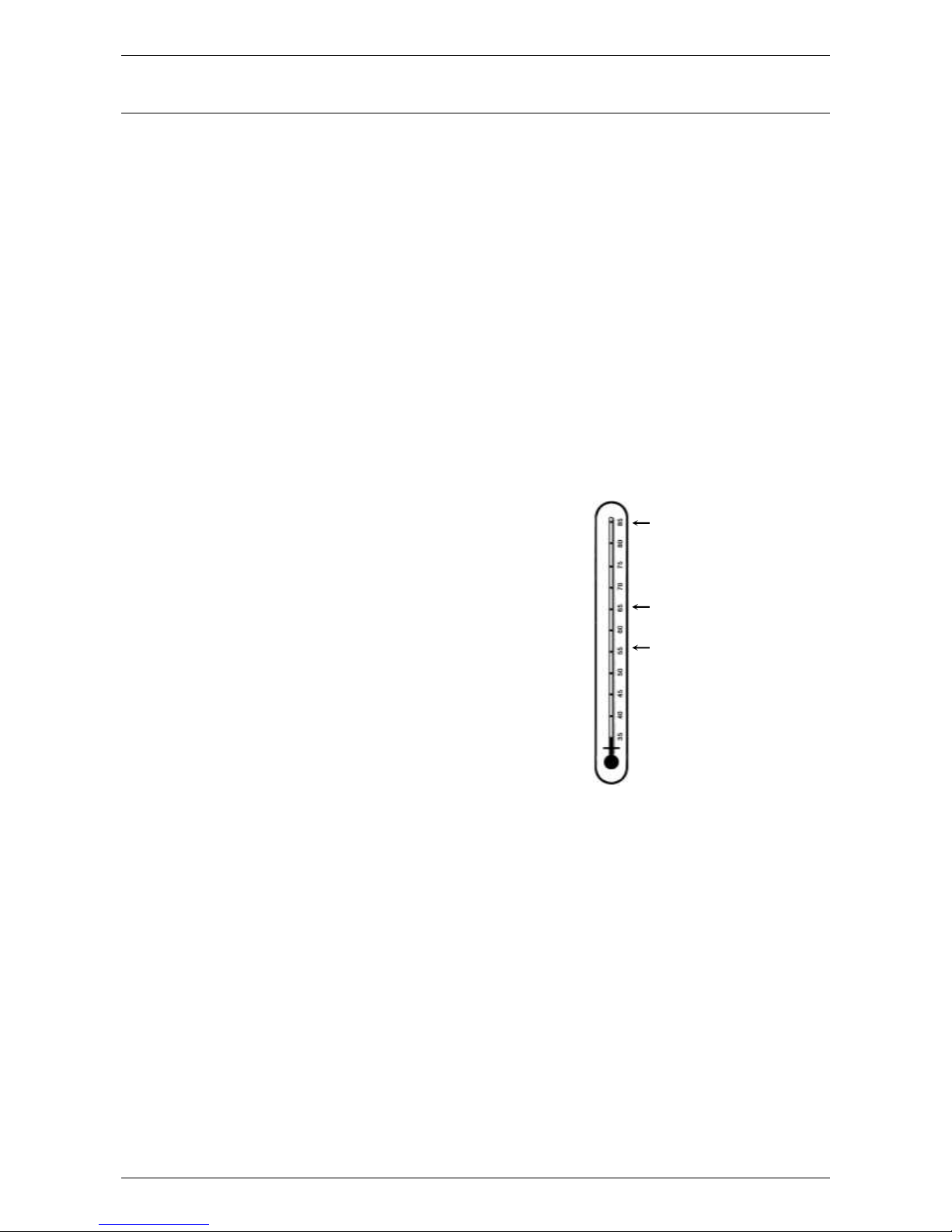
maximum allowable
thermostat setting of primary
heating source (90°C)
minimum recommended
thermostat setting of
secondary heating source
maximum recommended
supply temperature to
bathrooms, ensuites and
public areas
Page 5

ABOUT YOUR STORAGE TANK
5
Warning
This storage tank is only intended to be operated by persons who have the experience or the knowledge and
the capabilities to do so. This storage tank is not intended to be operated by persons with reduced physical,
sensory or mental capabilities i.e. the infirm, or by children. Children should be supervised to ensure they do
not interfere with the storage tank.
SAFETY
This storage tank is supplied with a combination temperature pressure relief valve. When installed as
instructed in this manual, this valve has a rating of 575 kW. If the primary heating source has an output
exceeding this valve, additional relief valves are required. The valve(s) must not be tampered with or
removed. The storage tank and its primary heating source must not be operated unless each of these
devices is fitted and is in working order.
This storage tank is designed to be used in a closed circuit. Supplementary pressure relief devices such
expansion vessels, permanently venting the cylinder or using as a drain back solar system must be included
in the system design.
If a remote thermostat (Tankstat) is fitted to the storage tank and the electrical conduit is damaged, it must be
replaced by a qualified person in order to avoid a hazard. Phone Rheem Service or their nearest Accredited
Service Agent to arrange for an inspection.
Warning: For continued safety of this water heating system it must be installed, operated and maintained
in accordance with the Owner’s Guide and Installation Instructions.
The Rheem warranty may not cover faults if relief valves or other safety devices are tampered with or
if the installation is not in accordance with these instructions.
PRECAUTIONS
Where damage to property can occur in the event of the storage tank leaking, the storage tank must be
installed in a safe tray. Construction, installation and draining of a safe tray must comply with AS/NZS 3500.4
and all local codes and regulatory authority requirements.
The storage tank must be maintained in accordance with the Owner’s Guide and Installation Instructions.
Refer to “Regular Care” on page 7.
If this storage tank is to be used where an uninterrupted hot water supply is necessary for your application or
business you should ensure that you have back up redundancy within the hot water system design. This
should ensure the continuity of hot water supply in the event that this storage tank were to become inoperable
for any reason. We recommend you seek advice from your plumber or specifier about your needs and
building back up redundancy into your hot water supply system.
TO TURN OFF THE STORAGE TANK
If it is necessary to turn off the storage tank:
Turn off the primary water heating plant and switch off the electrical supply at the isolating switch to the
circulating pump(s).
Close the cold inlet isolation valve on the cold inlet line to the storage tank(s) to shut down the entire
system, or;
Close the isolation valves on the cold, flow / return and hot branches to shut down an individual storage
tank in a bank.
TO TURN ON THE STORAGE TANK
Open the isolation valves fully on the cold, flow / return and hot water branches to the storage tank(s)
installed in a bank.
Open the cold inlet isolation valve on the cold inlet line to the storage tank(s). Air will be forced out of the
System.
Switch on the electrical supply at the isolating switch to the circulating pump(s) and turn on the primary
water heating plant.
Page 6

ABOUT YOUR STORAGE TANK
6
HOW DO I KNOW IF THE STORAGE TANK IS INSTALLED CORRECTLY?
Refer to the Application Guide for the most appropriate system configuration. Further information is also
provided on pages 20 to 21. The storage tank must be installed:
by a qualified person, and
in accordance with the installation instructions, and
in compliance with Standard AS/NZS 3500.4 and all local codes and regulatory authority requirements.
In New Zealand the installation must also conform with the New Zealand Building Code.
VICTORIAN CUSTOMERS
Notice to Victorian Customers from the Victorian Plumbing Industry Commission. This storage tank must be
installed by a licensed person as required by the Victorian Building Act 1993.
Only a licensed person will give you a Compliance Certificate, showing that the work complies with all the
relevant Standards. Only a licensed person will have insurance protecting their workmanship for 6 years.
Make sure you use a licensed person to install this storage tank and ask for your Compliance Certificate.
DOES THE WATER CHEMISTRY AFFECT THE STORAGE TANK?
The storage tank is designed to store a heat transfer liquid and must be treated to prevent corrosion. The
system has either been supplied with the amount of preparation chemicals and corrosion inhibitor required
or alternatively can be sourced locally. These are to be applied in accordance with the manufacturers’
instructions. Refer to SDS sheets supplied with pre-treatment and corrosion inhibitor. Refer to Treating the
Storage Tank on page 24.
Some water chemistries may have detrimental effects on the storage tank, its components and fittings. Refer
to “Water Supplies” on page 9.
If you are in a known harsh water area or you are not sure of your water chemistry, have your water checked
against the conditions described on pages 9 to 9.
HOW LONG WILL THE STORAGE TANK LAST?
The storage tank is supported by a manufacturer’s warranty (refer to page 31). There are a number of factors
that will affect the length of service the storage tank will provide. These include but are not limited to the fluid
chemistry, the fluid pressure, the fluid temperature (inlet and outlet) and the water usage pattern. Refer to
“Precautions” on page 5.
Page 7

7
REGULAR CARE
MINOR SIX MONTH MAINTENANCE
It is recommended minor maintenance be performed every six months by a responsible officer.
The minor maintenance includes:
Check the water chemistry of the closed circuit fluid
Check the level of the closed circuit fluid
Check operation of any fill valves and/or expansion vessels
Operate the easing lever on the temperature pressure relief valve. It is very important you raise and
lower the lever gently. Refer to “Temperature Pressure Relief Valve” on page 8.
Warning: Exercise care to avoid any splashing of water, as water discharged from the drain line will
be hot. Stand clear of the drain line’s point of discharge when operating the valve’s lever.
Check the drain line from the safe tray (if one is installed) is not blocked.
MAJOR FIVE YEAR SERVICE
It is recommended a major five year service be conducted on the storage tank. The service must be
conducted by a qualified person. Phone Rheem Service or their nearest Accredited Service Agent.
Note: The five year service and routine replacement of any components, such as the relief valve(s), are not
included in the Rheem warranty. A charge will be made for this work. Only genuine replacement parts should
be used on this storage tank.
The major service includes the following actions:
Replace the temperature pressure relief valve.
Check the water chemistry of the closed circuit fluid
Check the level of the closed circuit fluid
Check operation of any fill valves and/or expansion vessels
Visually check the unit for any potential problems.
Inspect all connections.
Check the drain line from the safe tray (if one is installed) is not blocked.
Note: The storage tank may need to be drained during this service. After the completion of the service, the
water heater will take some time to reheat the water. Depending upon the heating source, hot water may not
be available for a while.
Page 8
REGULAR CARE
8
TEMPERATURE PRESSURE RELIEF VALVE
This valve is near the top of the storage tank and is essential for its
safe operation. This valve is designed to only relieve excess thermal
energy or an unanticipated build-up of pressure. In a fully flooded
closed loop system an appropriately sized expansion vessel must be
installed to accommodate for the expansion of heat transfer liquid. It
must be sized to accommodate the pressure of the full capacity of
the system and its thermal expansion. In a drain back design the
system is not filled to 100% of its capacity, therefore an expansion
vessel is not required. The heat transfer liquid will expand into the
remaining empty capacity of the system.
The relief valve may discharge some fluid on first heat up. Continued
leakage of fluid from the valve and its drain line may indicate a
problem with the water heater (refer to “Temperature Pressure
Relief Valve Running” on page 10).
Warning: Never block the outlet of this valve or its drain line for
any reason.
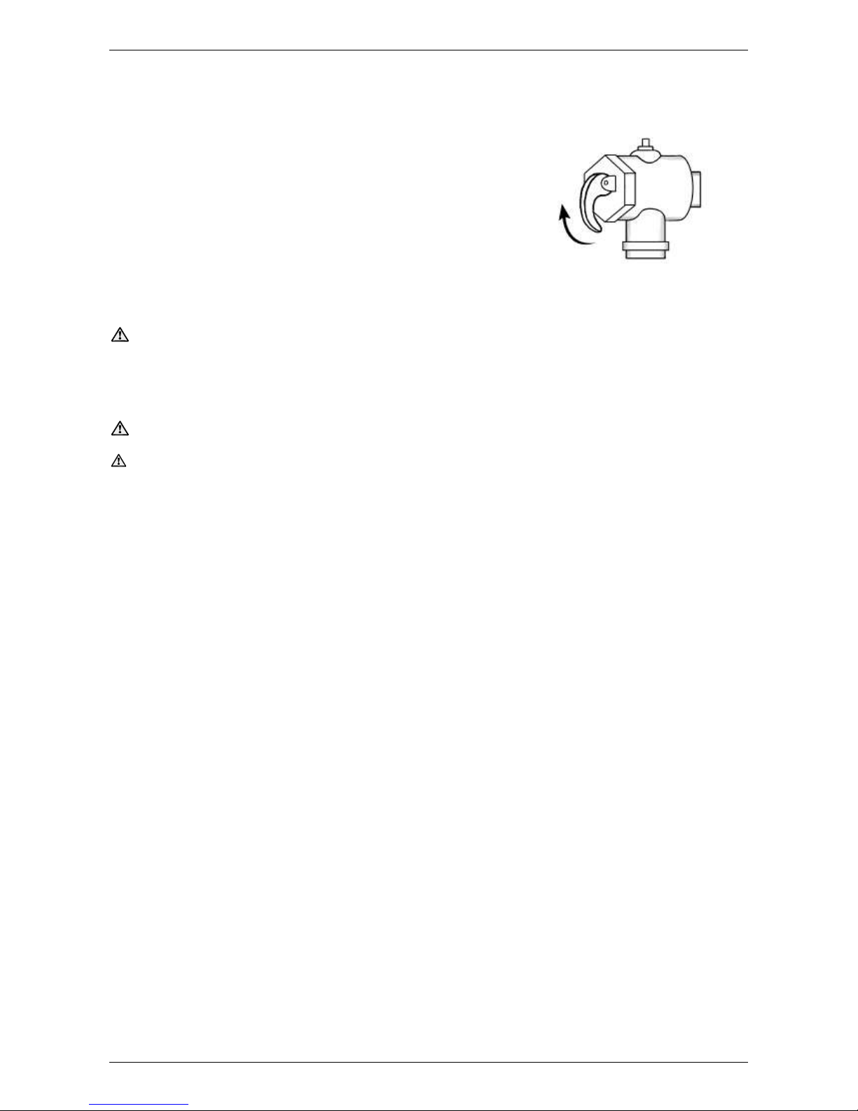
Operate the easing lever on the temperature pressure relief valve once every six months. Refer to “Minor Six
Month Maintenance” on page 7. It is very important the lever is raised and lowered gently.
Warning: Failure to do this may result in the storage tank cylinder failing.
Warning: Exercise care to avoid any splashing of fluid, as fluid discharged from the drain line will be hot.
Stand clear of the drain line’s point of discharge when operating the valve’s lever.
If fluid does not flow freely from the drain line when the lever is lifted, then the storage tank must be checked.
Phone Rheem Service or their nearest Accredited Service Agent.
The temperature pressure relief valve should be replaced at intervals not exceeding 5 years, or more
frequently in areas where there is a high incidence of water deposits (refer to “Water Supplies” on page 9).
Storage
tank
Drain
line
Lift until fluid
flows from the
drain line –
lower gently
Page 9

ERROR! REFERENCE SOURCE NOT FOUND.
9
WATER SUPPLIES
This water heater must be installed in accordance with this advice to be covered by the Rheem warranty.
The storage tank is designed to store a heat transfer liquid and must be treated to prevent corrosion. Refer to
Treating the Storage Tank on page 24, however, there are some known water chemistries which can have
detrimental effects on the water heater and its operation and / or life expectancy.
A list of postcodes is available on the Rheem website (www.rheem.com.au) indicating known areas where the steel
cylinder is not covered by the Rheem warranty due to the water chemistry of the area. The list is not necessarily
exhaustive and there may be areas outside of these postcodes where the steel cylinder is not covered by the
Rheem warranty due to the water chemistry of the area.
If you are unsure of your water chemistry, you may be able to obtain information from your local water supply
authority. This water heater should only be connected to a water supply which complies with these guidelines, which
takes precedence over the list of postcodes, for the Rheem warranty to apply.
PH
pH is a measure of whether the water is alkaline or acid. In an acidic or very alkaline water supply, the water can
attack steel parts and cause them to fail.
Where the pH is less than 6.0 or greater than 9.5, the Rheem warranty does not apply to the steel cylinder. Water
with a pH less than 6.0 may be treated to raise the pH.
The water supply from a rainwater tank in a metropolitan area is likely to be corrosive due to the dissolution of
atmospheric contaminants. This may result in pH of less than 6.0. It is recommended an analysis on the water from
a rainwater tank be conducted prior to connecting this type of water supply to a water heater with a steel cylinder.
SATURATION INDEX
The saturation index (SI) is used as a measure of the water’s corrosive or scaling properties. The saturation index
figures stated are calculated using a water temperature of 80°C.
In a corrosive water supply, the water can attack copper parts and cause them to fail.
In a scaling water supply calcium carbonate is deposited out of the water onto any hot metallic surface.
Where the saturation index exceeds +0.40, the water is very scaling. Where the saturation index exceeds +0.80,
the Rheem warranty does not apply to the steel cylinder.
Water which is scaling may be treated with a water softening device to reduce the saturation index of the water.
TOTAL DISSOLVED SOLIDS
The steel cylinder is only covered by the Rheem warranty when the total dissolved solids (TDS) content in the water
is less than 600 mg / L.
Note: Some water analysis reports may state the conductivity of the water rather than the level of total dissolved
solids. Conductivity, measured in microsiemens per centimetre (µS / cm), is directly proportional to the TDS content
of the water. TDS, in mg / L, is approximately 70% of the conductivity in µS / cm.
SUMMARY OF WATER CHEMISTRY ADVICE AFFECTING WARRANTY
The water heater and its components are not suitable for certain water chemistries. Those chemistries are listed
below. If the water heater is connected at any time to a water supply with the following water chemistry, the Rheem
warranty will not cover any resultant faults on the components listed below:
Water Chemistry
Component
pH < 6.0 or > 9.5
water heater cylinder
Total Dissolved Solids (TDS) > 600 mg / L
water heater cylinder
Saturation Index (SI) > +0.4
water heater cylinder
temperature pressure relief valve
Saturation Index (SI) > +0.8
water heater cylinder
Page 10
10
SAVE A SERVICE CALL
Check the items below before making a service call. You will be charged for attending to any condition or
fault that is not related to manufacture or failure of a part.
NOT ENOUGH HOT WATER (OR NO HOT WATER)
Are you using more hot water than you think?
Are outlets (especially the showers) using more hot water than you
think? Very often it is not realised the amount of hot water used,
particularly when showering. Carefully review the hot water usage.
Have your plumber fit a flow control valve to each shower outlet to
reduce water usage.
Temperature pressure relief valve running
Is the relief valve discharging too much water? Refer to
“Temperature Pressure Relief Valve Running” on page 10.
Thermostat setting
Ensure the thermostat setting of the primary heating source is
appropriate. You may choose to have your electrician adjust the
thermostats upwards to gain additional hot water capacity.
Warning: Hotter water increases the risk of scald injury.
Water heater size
Do you have the correct size water heater or sufficient storage for your requirements? The sizing guide in
the Rheem sales literature and on the Rheem website (www.rheem.com.au) suggests average sizes that
may be needed.
TEMPERATURE PRESSURE RELIEF VALVE RUNNING
Normal Operation
This valve is designed to only relieve excess thermal energy or an
unanticipated build-up of pressure. In a fully flooded closed loop
system an appropriately sized expansion vessel must be installed
to accommodate for the expansion of heat transfer liquid. It must
be sized accordingly to accommodate the pressure of the full
capacity of the system and its thermal expansion. In a drain back
design the system is not filled to 100% of its capacity, therefore an
expansion vessel is not required. The heat transfer liquid will
expand in to the remaining empty capacity of the system.
Continuous dribble
Try gently raising the easing lever on the relief valve for a few
seconds (refer to “Temperature Pressure Relief Valve” on page 8).
This may dislodge a small particle of foreign matter and clear the
fault. Release the lever gently.
The relief valve may discharge some fluid on first heat up.
Continued leakage of fluid from the valve and its drain line may indicate a problem with the water heater
Heavy flows of hot fluid or steam
The primary heating source must be shut down and the energy source isolated. Phone Rheem Service
or their nearest Accredited Service Agent to arrange for inspection.
Warning: Never replace the relief valve with one of a higher pressure rating.
IF YOU HAVE CHECKED ALL THE FOREGOING AND STILL BELIEVE YOU NEED ASSISTANCE,
PHONE RHEEM SERVICE OR THEIR NEAREST ACCREDITED SERVICE AGENT
Page 11

11
INSTALLATION
THIS STORAGE TANK IS NOT SUITABLE FOR POOL HEATING
INSTALLATION STANDARDS
The storage tank must be installed:
by a qualified person, and
in accordance with the installation instructions, and
in compliance with Standard AS/NZS 3500.4 and all local codes and regulatory authority requirements.
In New Zealand the installation must also conform to the New Zealand Building Code.
All packaging materials must be removed from the storage tank prior to its installation. This includes the
removal of the cardboard base of the carton from the underside of the storage tank.
STORAGE TANK APPLICATION
This storage tank is designed for the purpose of storing water treated with a corrosion inhibitor and is not
designed for use with potable water. Its use in an application other than this may shorten its life.
If this storage tank is to be used where an uninterrupted hot water supply is necessary for the application or
business, then there should be redundancy within the hot water system design. This should ensure the
continuity of hot water supply in the event that this storage tank was to become inoperable for any reason.
We recommend you provide advice to the system owner about their needs and building backup redundancy
into the hot water supply system.
Note: AS 3498 requires that a water heater provides the means to inhibit the growth of Legionella bacteria in
potable water.
This storage tank is not designed to contain potable water. The requirement to provide the means to inhibit
the growth of Legionella bacteria must be fulfilled by the secondary heating source. Refer to installation
instructions of the secondary heating source.
STORAGE TANK LOCATION
This storage tank is suitable for either outdoor or indoor installation, depending on the selected insulation.
Aluminium clad insulation is suitable for indoor or outdoor installation. PVC outer cover is suitable for indoor
installation only (not available in Australia or New Zealand).
Whether located outdoor or indoor, the storage tank should be installed either close to the most frequently
used outlets or with a circulated flow and return system, and its position chosen with safety and service in
mind.
Clearance must be allowed for servicing of the storage tank. The
storage tank must be accessible without the use of a ladder or scaffold.
Make sure the temperature pressure relief valve lever is accessible and
the thermostat (Tankstat) if fitted can be removed for service.
You must be able to read the information on the rating plate.
Remember you may have to take the entire storage tank out later for
servicing.
The storage tank is to be installed at ground or floor level and must
stand vertically upright on a stable base as acceptable to local
authorities. The support Legs of the storage tank are coated with a
corrosion resistant material, however it is recommended a moisture
barrier be placed between the support legs and the supporting surface.
It is not necessary to allow for free air circulation under the base of the
storage tank.
Page 12

INSTALLATION
12
Note: The storage tank should not be placed in direct contact with a concrete surface that is less than two
months old and not fully cured as this may attack the metal coating of the storage tank base. A moisture
barrier must be used between the two surfaces in this instance.
It is important to have the heater in position before installing the insulation. (Refer to page 14)
Lifting of Storage Tank
Each storage tank is supplied with suitable lifting lugs located at the top of the cylinder. Refer to storage tank
technical data and the rating plate for tank weight. For other than 1000L tanks, the tank must be lifted from
the horizontal into its vertical orientation. Take care when removing the straps from the palletised storage
cylinder as they may be under tension. Employ safe lifting techniques when locating the tank during
installation.
Remember all local authorities have regulations about putting storage tanks into roof spaces.
Refer to the instructions on pages 20 for storage tank installation options. Refer to the Application Guide for
the most appropriate configuration.
SAFE TRAY
Where damage to property can occur in the event of the storage tank leaking, the
storage tank must be installed in a safe tray or the area be suitably bunded.
Construction, installation and draining of a safe tray must comply with
AS/NZS 3500.4 and all local codes and regulatory authority requirements.
AS/NZS 3500.4 also has particular requirements when a safe tray must be installed.
SUPPLY PRESSURE
The supply pressure must not exceed that shown in the table below.
Tank Nominal Capacity
1000 – 5000 L
Relief valve setting
500kPa
Max. supply pressure
400kPa
If the storage tank is supplied with water from a tank supply the minimum pressure must be suitable for any
primary heating source attached to the storage tank. Refer to the installation instructions of the primary
heating source
Hot Water Delivery
This storage tank can deliver water at temperatures which can cause scalding.
It is necessary and we recommend that a temperature limiting device be fitted between the storage tank and
the hot water outlets in any ablution and public areas such as bathrooms, ensuites or public amenities to
reduce the risk of scalding. The installing plumber may have a legal obligation to ensure the installation of this
storage tank meets the delivery water temperature requirements of AS/NZS 3500.4 so that scalding water
temperatures are not delivered to a bathroom, ensuite, or other ablution or public area.
Refer to instructions supplied with secondary water heating plant for further information regarding the
application of temperature limiting devices.
REDUCING HEAT LOSSES
The cold water line to, primary flow and return lines and the hot water line from the storage tank must be
insulated in accordance with the requirements of AS/NZS 3500.4. The insulation must be weatherproof and
UV resistant if exposed.
Keep temperature settings down. Lower temperatures reduce heat losses and prolong cylinder life.
SADDLING PIPE WORK
Pipe work must not be saddled to the tank.
Note: If the cylinder or insulation is damaged as a result of attaching pipe clips or saddles to the
jacket, any resultant faults will not be covered by the Rheem warranty.
Page 13

INSTALLATION
13
DIMENSIONS AND TECHNICAL DATA
DIMENSIONS TABLE
Model Designation
1000
2000
3000
4000
5000
Storage capacity
Litres
920
2055
2960
3820
5180
Dimensions
A
mm
2200
2565
2845
2918
3128
B
mm
1000
1300
1450
1600
1800
C
mm
800
1100
1250
1400
1600
D
mm
510
555
600
628
747
E
mm
1435
1735
1945
1963
2132
F
mm
417
462
505
533
667
G
mm
879
1024
1135
1163
1287
H
mm
1341
1586
1765
1793
1907
J
mm
1803
2148
2395
2423
2527
K
degree
50
50
50
50
50
L
degree
35
35
35
35
35
M
degree
75
75
75
75
75
Weight Empty
kg
115
245
334
455
535
Inlet/Outlet Connections (BSPF)
RP2
RP2
RP2
RP2
RP2
T&PR Valve Connection (NPTF)*
1¼”
1¼”
1¼”
1¼”
1¼”
Vent Connection (BSPF)
RP11/2
RP2
RP2
RP2
RP2
Drain Connection (BSPF)
RP1
RP1
RP1
RP1
RP1
Remote Thermostat Connection (thermowell)
RP½
RP½
RP½
RP½
RP½
*TPR tundish is supplied with 11/4” NPT to BSP adaptor
Page 14

INSTALLATION
14
INSULATION - INSTALLATION INSTRUCTIONS
ALUMINIUM CLADDING
Ensure the drain is fitted or plugged. Ensure the
tank is in position where it’s going to be installed,
as it can be difficult to move once the insulation
is attached.
The insulation comes in multiple sections that will vary
both in quantity and layout depending on the size of the
tank. These sections clip together along the edges
using a tooth lock system.
Fit the two green foam insulation rings around
the upper and lower flange. Fit the two black
plastic flange covers over the foam rings.
There are 14 plastic fitting surrounds, these vary in
size and should fit tightly around the fittings. The
fitting surrounds are placed on after the panel and
should sit flush with the front of the fitting. Attach the
fitting surrounds as each panel is put in place, this will
help to hold the section in the correct position as
each panel is added.
When the first panel is in place, fit the panel to
the left using the same process. Where the
sections meet there are 5 teeth that clip
together. We recommend joining to the outside
tooth until all sections are together.
Take the section that has the two larger holes and line
them up with the flanges on the tank. The bottom of the
insulation should be touching the ground. If there are
further holes in the panel fit them over the fittings
ensuring the insulation is clear of the fittings.
Page 15

INSTALLATION
15
There are two round pieces of insulation that fit on top
of the tank. The smaller white high density foam piece
fits over the top fitting and the larger green piece fits
around the white piece.
The aluminium disk may be supplied in one piece or two
semi circles depending on the tank size. Fit on top of the
insulation.
Locate the two aluminium dress rings around each flange
cover. Rivet them in two places on the horizontal plane.
Fit the final top fitting surround in the centre.
Note: 5000L – the semi-circle with 2 x
standouts fits the side that houses the
flanges.
Aluminium Disk
The large plastic lid may be supplied in one piece or
two semi circles depending on the tank size. Place the
large plastic lid or the two halves on top of the tank.
If supplied in two semi circles use the plastic plugs
(supplied) to join along where the two halves meet.
Drill and screw the lid to the top of the tank at each
panel.
Dress Rings
Continue using the same process to wrap each panel
around the tank. Once all panels are joined each panel
should be tightened into the last tooth if possible. Ensure
the teeth are fully engaged along the entire length.
Drill and fit 1 x screw
(supplied) into each tooth
lock section midway between
the top and the bottom
Page 16

INSTALLATION
16
PVC OUTER COVER
Ensure the drain is fitted
or plugged. Ensure the
tank is in position where
it’s going to be installed,
as it can be difficult to
move once the insulation
is attached.
Fit the two green foam insulation rings around the
upper and lower flange. Fit the two black plastic
flange covers over the foam ring.
The insulation can come in multiple sections that
will vary both in quantity and layout depending on
the size of the tank. These sections zip together
along the edges.
Line up the section that has the two
larger holes with the flanges on the
tank. The bottom of the insulation
should be touching the ground. If there
are further holes in the section fit them
over the fittings ensuring the insulation
is clear of the fittings.
There are 14 plastic fitting surrounds, these vary in size
and should fit tightly around the fitting. The fitting surrounds
are placed on after the insulation and should sit flush with
the front of the fitting. Attach the fitting surrounds as each
section is put in place, this will help to hold the section in
the correct position as each is added.
When the first panel is in place, fit the section to the left
using the same process. Where the sections meet zip
together. Make sure to relieve the stress from the zipper
by pulling in the two sections either side of the zipper.
Note: failure to observe this precaution may result in
damage to the zipper / insulation.
The large plastic lid may be supplied in one piece or two semi circles depending
on the tank size. Place the large plastic lid or the two halves on top of the tank.
If supplied in two semi circles use the plastic plugs (supplied) to join along where
the two halves meet. Fit the final top fitting surround in the centre.
There are two round pieces of
insulation that fit on top of the tank.
The smaller white high density foam
piece fits over the top fitting and the
larger green piece fits around the
white piece.
Page 17

17
CONNECTIONS – PLUMBING
All plumbing work must be carried out by a qualified person and in accordance with the Standard
AS/NZS 3500.4 and all local codes and regulatory authority requirements. In New Zealand the installation
must also conform with the New Zealand Building Code.
CONNECTION SIZES
The storage tank is supplied with many fittings allowing maximum
flexibility in system design and layout. Refer to the Application
Guide for specific application connection details.
Disconnection unions and isolation valves must be installed on all
piping connections to the storage tank.
Unused fittings must be plugged (plugs not supplied).
WATER INLET AND OUTLET
All pipe work must be cleared of foreign matter before
connection and purged before attempting to operate the
storage tank. All olive compression fittings must use brass
or copper olives. Use thread sealing tape or approved
thread sealant on all fittings.
HEAT TRAP
An external heat trap is required be installed. The heat trap
is to be within one (1) metre of the hot water outlet, before
the first hot water branch and have a vertical drop of
250 mm from the outlet of the water heater.
PIPE SIZES
The pipe sizing of hot water supply systems for commercial installations should be carried out by persons
competent to do so, choosing the most suitable pipe size for each individual application. Reference to the
technical specifications of the primary heating source, storage tank and local regulatory authority
requirements must be made.
TEMPERATURE PRESSURE RELIEF VALVE
The temperature and pressure relief valve is shipped with the tank. It comes in a separate box that contains,
the TPR, NPT to BSP adaptor, tundish and thermostat well. The temperature pressure relief valve must be
fitted before the storage tank is operated. Before fitting the relief valve, make sure the probe has not been
bent. Seal the thread with an approved thread sealant such as Teflon tape - never hemp. Make sure the tape
does not hang over the end of the thread.
Screw the valve into the correct opening (refer to the fitting location diagram on page 17) leaving the valve
drain pointing downwards. Do not use a wrench on the valve body - use the spanner flats provided. A copper
drain line must be fitted to the temperature pressure relief valve (refer to "Relief Valve Drain" on page 18).
Fitting
Description
A, B, C, D, E, F, G, H
AUXILIARY FITTINGS RP2 BSPF
J, K, L, M
TEMPERATURE SENSOR PORTS
RP½ BSPF
N
TPR SOCKET 1¼” NPTF
P
TOP ELEMENT FLANGE
Q
BOTTOM ELEMENT FLANGE
R
DRAIN RP1 BSPF
T
DRAIN BACK VENT:
1000L = RP1½ BSPF
2000, 3000, 4000, 5000L = RP2 BSPF
V
LIFTING LUGS
Heat Trap
Page 18

CONNECTIONS – PLUMBING
18
The tundish MUST be installed for the nominated energy rating to be valid.
The valve must be insulated with closed cell polymer insulation or similar (minimum thickness 9 mm) and the
insulation installed so as not to impede the operation of the valve. The insulation must be weatherproof and
UV resistant if exposed.
TPR Valve Assembly
RELIEF VALVE DRAIN
DN32 copper drain lines must be fitted to the temperature pressure relief valve and expansion control valve
(if one is installed) to carry the discharge clear of the storage tank. Connect the drain lines to the valves using
disconnection unions. The drain line from the valve to the point of discharge should be as short as possible,
have a continuous fall all the way from the storage tank to the discharge outlet and have no tap, valves or
other restrictions in the pipe work. A drain line from a relief valve must comply with the requirements of
AS/NZS 3500.4.
A drain line must be no longer than 9 metres with no more than three bends greater than 45° before
discharging at an outlet or air break. The maximum length of 9 metres for a drain line is reduced by 1 metre
for each additional bend required of greater than 45°, up to a maximum of three additional bends. Where the
distance to the point of final discharge exceeds this length, the drain line can discharge into a tundish.
Subject to local regulatory authority approval, the drain lines from the temperature pressure relief valve and
expansion control valve from an individual storage tank may be interconnected.
The outlet of a drain line must be in such a position that flow out of the pipe can be easily seen, but arranged
so discharge will not cause injury, damage or nuisance. The termination point of a drain line must comply with
the requirements of AS/NZS 3500.4. Drain lines must not discharge into a safe tray.
In locations where water pipes are prone to freezing, drain lines must be insulated, must not exceed 300 mm
in length and are to discharge into a tundish through an air gap of between 75 mm and 150 mm.
If a drain line discharges into a tundish, the drain line from the tundish must be not less than DN32. The drain
line from a tundish must meet the same requirements as for a drain line from a relief valve.
For multiple installations the drain lines from several storage tanks can discharge into a common tundish
(refer to “Multiple Installations” on page 20).
Warning: As the function of the temperature pressure relief valve on this storage tank is to discharge
high temperature water under certain conditions, it is strongly recommended the pipe work downstream of
the relief valve be capable of carrying water exceeding 93°C. Failure to observe this precaution may result in
damage to pipe work and property.
TPR Valve
NPT to BSP Adaptor
Tundish
11/4” NPT
RP11/4
Page 19

CONNECTIONS – PLUMBING
19
WARNING: Plumber – Be Aware
The primary flow and return pipes between the storage tank(s) and the primary water heating source,
including the solar hot and solar cold pipes between the solar storage tank(s) and the solar collectors,
MUST BE of copper, or metallic. All compression fittings must use brass or copper olives.
Plastic pipe MUST NOT be used, as it will not withstand the temperature of the fluid generated by the
primary heating source under certain conditions. The primary heating source may generate extremely
high fluid temperatures and high fluid pressure of 500 kPa. Plastic pipe cannot withstand these
temperatures and pressures, and MUST NOT be used. Failure of plastic pipe can lead to the release
of high temperature fluid and cause severe water damage and flooding.
The full length of the primary flow and return pipes MUST BE insulated.
The insulation must:
be of a type suitable for the application and capable of withstanding the temperature of the water
generated by the primary water heating source
The specification of the chosen insulation material should be checked with the insulation
manufacturer prior to installation as different materials may vary in temperature tolerance.
Closed cell type or equivalent insulation used between the storage tank(s) and solar collectors, if
this storage tank is part of a solar water heater installation, must be able to withstand the
temperature of the water generated by the solar collectors under stagnation conditions. Refer to
the installation instructions provided with the solar controller for full details on the insulation
requirements of the solar hot and solar cold pipes.
be at least 13 mm thick, however thicker insulation may be required to comply with the
requirements of AS/NZS 3500.4
be weatherproof and UV resistant if exposed
be fitted up to and cover the connections on both the storage tank(s) and the primary heating
source.
The insulation will reduce pipe heat losses and also assist in avoiding accidental contact with the pipe
work as high temperature water can flow from the primary heating source and the storage tank(s).
In addition, the insulation on the solar hot and solar cold pipes must also:
extend through any penetrations in the eaves, ceiling and roof
cover valves and fittings in the solar hot and solar cold pipe work
Note: Failure to observe these requirements also increases the risk of freeze damage.
The insulation is essential to assist in providing freeze protection and will offer corrosion protection to
a metal roof against water runoff over the copper pipe.
Uninsulated pipe work, including concealed in cavities and roof spaces or where it may be in contact
with a metal roof, may lead to freeze damage. The system has NO WARRANTY for freeze damage if
the solar hot and solar cold pipes are not insulated in accordance with the installation instructions.
Page 20

20
MULTIPLE INSTALLATIONS
A multiple installation of storage tanks on a single manifold or multiple manifolds is possible, using the EquaFlow® manifold system, where large volumes of hot water is required. The Equa-Flow principle will function
with storage tanks in line, around a corner or in rows back to back (refer to the diagrams on page 21).
The cold fluid and hot fluid manifolds must be designed to balance the flow from each storage tank. To
achieve this, there are basic installation requirements and principles which must be followed:
1. The maximum number of storage tanks in a bank should be 10, however several banks of storage tanks
can be installed.
2. The hot fluid line from the manifold must leave from the opposite end to which the cold water line enters
the manifold.
3. The storage tanks must be of the same model.
4. The cold fluid line, cold and hot headers and hot fluid line must be sized to meet the requirements of both
AS/NZS 3500.4 and the application.
5. The primary flow and return lines must be sized to meet the requirements of AS/NZS 3500.4 and suit the
primary heating source. Refer to the literature supplied with the primary heating source.
6. A full flow gate valve or ball valve (not a stop tap, as used on a single storage tank installation) must be
installed on the cold fluid branch, primary flow /return branch and hot fluid branch of each storage tank.
7. Non return valves or pressure limiting valves must not be installed on the branch lines to the storage
tanks.
8. All fittings, valves and branch lines must be matched sets all the way along the manifold.
9. Sufficient space must be left to enable access, servicing or removal of any storage tank.
10. The temperature pressure relief valve drain line from each storage tank can terminate at a common
tundish (funnel) with a visible air break at each drain discharge point (refer to the diagram on page 21
and to “Relief Drain Line” on page 18).
Refer to the Application Guide for the most appropriate system configuration.
Page 21

ERROR! REFERENCE SOURCE NOT FOUND.
21
Single Bank of Storage Tanks
Multiple Banks of Storage Tanks
TPR Valve Drain Line
Common Discharge Point
Back to Back Manifold
Angle Manifold
In Line Manifold
Page 22

22
CONNECTIONS – ELECTRICAL
The power supply to the primary heating source and circulating pumps must not be switched on until
the storage tank is filled with fluid and a satisfactory megger reading is obtained.
No electrical connections are to be made on the storage tank, except if a remote thermostat or electric
heating unit bundle if fitted. All electrical work and permanent wiring must be carried out by a qualified person
and in accordance with the Wiring Rules AS/NZS 3000 and all local codes and regulatory authority
requirements.
REMOTE THERMOSTAT
The storage tank is fitted with 4 x RP1/2 fittings which can be used to monitor system temperature.
1 x thermostat well is supplied with the storage tank, located in the TPR valve box.
Thermowell Dimensions
ELECTRIC HEATING UNIT BUNDLE
The tanks can be fitted with an electric heating unit bundle. The
heating unit bundle is supplied with a digital thermostat which
can be adjusted to suit site specific requirements. Also included
is all switch gear and over temperature energy cut out (ECO).
The heating unit electrical connections are housed in an IP55
enclosure and the bundle connects to the storage tank via a 16
bolt flange and gasket.
The elements are low watts density incoloy 800, designed to
provide long service life. A variety of kW ratings are available.
Note: not all element ratings suit all tank capacities. The
elements can be fitted in the top flange for “in-tank” boosting of the solar heat store or located in the bottom
flange of a tank when connected as an “in series” solar booster or electric water heater.
Refer to the heating unit manual for heating unit details and installation requirements.
6.5 ID
Page 23

23
FLANGE DETAILS
The storage tank is supplied with two flanges to allow the fitment of auxiliary heating such as heat exchange
coils (not supplied) or an electric heating unit bundle. The tanks are supplied from the factory with the flange
openings capped with a stainless steel plate, EPDM gasket and plastic flange cover.
Each tank is fitted with two 16 bolt flanges consisting of 16 threaded holes X M12 equi-spaced with holes
orientated symmetrical to the centre line.
Tank Flange Dimensions
Page 24

24
CORROSION INHIBITOR
The storage tank must be treated to prevent corrosion. The system has either been supplied with the
amount of preparation chemicals and corrosion inhibitor required or alternatively can be sourced locally.
These are to be applied in accordance with the manufacturers’ instructions. Refer to SDS sheets supplied
with pre-treatment and corrosion inhibitor.
Corrosion inhibitor must be used and maintained in accordance with this instruction in order for the storage
tank to be covered by the warranty.
The following chemical treatment is recommended for optimum protection.
Pre-treatment with NALPREP® IV
Corrosion Inhibitor TRASARTM TRAC107PLUS
Refer to Material Safety Data Sheet supplied with product for safe use and disposal of these products.
Warning: Protective overalls, rubber or nitrile gloves and chemical splash goggles must be worn.
TREATING THE STORAGE TANK
1. Remove the plug from an unused fitting on a storage tank, preferably at the lowest point.
2. Using a funnel, pour Nalprep IV at a dose of 2.7L per 1000L of total storage tank volume into the
storage tank.
3. Add 15% of the weight of Nalprep IV of sulphuric acid (30%w/w) to the storage tank. This ratio can be
factored if different strengths of sulphuric acid are used. This is required to lower the pH of the water to
6.5 – 6.7.
4. Re-fit the plug on the tank.
5. Fill the system with clean water. Refer to Filling and Testing of Primary Circuit on page 25 for the
method to fill and pressure test the system and follow that procedure fully before returning to point (5)
below.
6. Once the system is filled and pressure tested with no leaks, ensure that the entire primary circuit is
open to water-flow (no isolated dead-legs) and circulate under no load (ie ambient water temperature).
7. Circulate for an absolute minimum of 8 hours, preferably 8-12 hours or overnight. During this time any
strainers should be checked for blockage and cleaned.
8. Drain the system. First release the pressure by gently releasing the lever on the TPR Valve. Observe
the pressure gauge and wait until pressure is completely released.
9. Open the air bleed valve and the drain fitting ‘R’ on each storage tank.
10. When completely drained, close the drain/s.
11. Add TRAC107PLUS to one of the storage tanks at a dose of 2 to 3L per 1000L of total storage tank
volume. Refit the plug and refill the system with clean water.
12. When water begins to flow from the air bleed valve, close the water supply isolation valve and close the
air bleed valve.
13. Close the isolation valve at the inlet and outlet of the Solar Pump Skid and remove the pressure gauge.
Cap the gauge spigot and reopen the Solar Pump Skid inlet isolation valve.
14. Unless connected to an auto fill valve and the incoming pressure is as described on page 12, remove
the mains water supply from the system.
Page 25

25
15. The closed circuit of the system is at ambient condition and the system is now ready for hand over.
Notes:
It is absolutely imperative that all of the Nalprep IV cleaning solution is purged from the
system prior to the introduction of corrosion inhibitor. Residual Nalprep IV means the system
has not been adequately drained/flushed and will still contains suspended material/corrosion
product. Residual Nalprep IV may also negatively impact the performance of the corrosion
inhibitor subsequently applied as well as act as potential food source for bacteria leading to
microbiological control issues in the future.
The waste produced by the cleaning procedure will contain approximately up to 500ppm of
o-PO4 and have a pH 6.5. The waste may also be turbid and contain much suspended iron. If
the volume of the system is large, the fate of the waste needs to be considered and a once-off
discharge permit obtained from the sewer provider. If required, the waste generated may have
the pH increased to pH 7.0 by the addition of a caustic product once the waste is out of the
chilled system.
When a system has been left idle during works, there exists the potential for some
microbiological contamination to be retained through the cleaning process. Therefore a
heightened level of microbiological monitoring is often required up to a few months after
inhibitor has been added to ensure that bacterial populations are not allowed to develop.
Please check with local EPA with regards to the disposal of the passivation chemicals. Contact
local Nalco representative.
FILLING AND PRESSURE TESTING OF PRIMARY CIRCUIT
For best results, pressure testing of the system should be conducted late in the evening when there is little
solar radiation and the collector array (if fitted) can remain flooded under pressure for around 60 minutes.
The maximum pressure that is allowed for testing of the system is 500 kPa (5 bar). When pressure testing
is to be conducted using mains pressure, ensure the mains pressure is reduced to 500 kPa (5 bar) before it
enters the system. Where the mains pressure is lower than the desired operating pressure of the system a
pressure testing pump (not supplied) shall be used for this purpose.
WARNING:
At no stage in the filling of the closed circuit should mains pressure greater than 500kPa be applied to
the storage tank without a pressure reducing valve.
1. Fit a pressure gauge capable of measuring up to 600kPa to the inlet of the system.
2. Open all isolation valves in the system, including any air bleed valves.
3. Connect the system to the mains water supply and begin to fill the system.
4. When water overflows from the air bleed valve, reduce the incoming water flow rate by slightly closing
the incoming water supply isolation valve.
5. Close the water supply isolation valve fully to stop the incoming water, and then close the air bleed
valve.
6. Now, slowly open the water supply isolation valve and continue filling. Check the pressure gauge
attached. When the pressure reaches 200kPa (2 bar), close the water supply isolation valve and allow
the pressure to stabilise.
Page 26

26
7. Repeat pressurising in incremental steps and allow stabilising until the operating pressure is reached.
8. Close the water supply isolation valve and observe the pressure.
9. Check for leaks at all the connections on the closed circuit. Should a leak be observed at any one of
the connections, immediately release the pressure by gently releasing the lever on the TPR valve in the
storage tank or at the air bleed valve. Rectify any leak that is observed and repeat the pressure test as
described above.
10. Hold the pressure in the system until the pressure remains steady for around 60 minutes.
11. After the pressure test, circulate the fluid. Return to step 6 in Treating the Storage Tank on page 24.
COMMISSIONING
Explain to a responsible officer the functions and operation of the water heating system. Upon completion of
the installation and commissioning of the water heating system, leave this guide with a responsible officer.
TO TURN OFF THE STORAGE TANK
If it is necessary to turn off the storage tank on completion of the installation, such as on a building site or
where the premises is vacant, then:
Shut down the primary water heating plant and switch off the electrical supply at the isolating switch to
the circulating pump(s).
Close the cold water isolation valve on the cold water line to the storage tank(s) to shut down the entire
system, or;
Close the isolation valves on the cold, flow / return and hot water branches to shut down an individual
storage tank in a bank
Page 27

27
DRAINING THE STORAGE TANK
Warning: Exercise care, as fluid discharged from the storage tank may be of a very high temperature.
To drain the storage tank:
Turn off the storage tank (refer to “To Turn Off The Storage Tank” on page 26).
Operate the relief valve release lever - do not let the lever snap back or you will damage the valve seat.
Operating the lever will release the pressure in the storage tank.
Undo the union at the cold inlet to the storage tank and attach a hose to the storage tank side of the
union.
Let the other end of the hose go to a drain.
Operate the relief valve again.
This will let air into the storage tank and allow the water to drain through the hose.
Alternatively if a drain line is installed, the system can be drained from the drain line connection point
located at the base of the cylinder in lieu of the cold inlet. If the drain line was not installed, the insulation
would have to be removed to gain access to the drain connection point.
Page 28

28
This page is intentionally blank
Page 29

29
This page is intentionally blank
Page 30

30
This page is intentionally blank
Page 31

31
RHEEM AUSTRALIA STORAGE TANK WARRANTY
STORAGE TANK MODELS : RT1000C6, RT2000C6, RT3000C6, RT4000C6, RT5000C6
ST1000C6, ST2000C6, ST3000C6, ST4000C6, ST5000C6
1. THE RHEEM WARRANTY – GENERAL
1.1 This warranty is given by Rheem Australia Pty Limited ABN 21 098 823 511 of 1 Alan Street, Rydalmere New South Wales.
1.2 Rheem offer a trained and qualified national service network who will repair or replace components at the address of the storage tank
subject to the terms of the Rheem warranty. Rheem Service, in addition can provide preventative maintenance and advice on the
operation of your storage tank. The Rheem Service contact number is available 7 days a week on 131031 with Service personnel
available to take your call from 8am to 8pm daily (hours subject to change).
1.3 For details about this warranty, you can contact us on 131031 or by email at warrantyenquiry@rheem.com.au (not for service
bookings).
1.4 The terms of this warranty and what is covered by it are set out in sections 2 and 3 and apply to storage tanks manufactured after
1st June 2015.
1.5 If a subsequent version of this warranty is published, the terms of that warranty and what is covered by it will apply to storage tanks
manufactured after the date specified in the subsequent version.
2. TERMS OF THE RHEEM WARRANTY AND EXCLUSIONS TO IT
2.1 The decision of whether to repair or replace a faulty component is at Rheem’s sole discretion.
2.2 If you require a call out and we find that the fault is not covered by the Rheem warranty, you are responsible for our standard call out
charge. If you wish to have the relevant component repaired or replaced by Rheem, that service will be at your cost.
2.3 Where a failed component or cylinder is replaced under this warranty, the balance of the original warranty period will remain effective.
The replacement does not carry a new Rheem warranty.
2.4 Where the storage tank is installed outside the boundaries of a metropolitan area as defined by Rheem or further than 25 km from
either a regional Rheem branch office or an Accredited Rheem Service Agent's office, the cost of transport, insurance and travelling
between the nearest branch office or Rheem Accredited Service Agent’s office and the installed site shall be the owner’s responsibility.
2.5 Where the storage tank is installed in a position that does not allow safe or ready access, the cost of that access, including the cost of
additional materials handling and/or safety equipment, shall be the owner’s responsibility. In other words, the cost of dismantling or
removing cupboards, doors or walls and the cost of any special equipment to bring the storage tank to floor or ground level or to a
serviceable position is not covered by this warranty.
2.6 This warranty only applies to the original and genuine Rheem storage tank in its original installed location and any genuine Rheem
replacement parts.
2.7 The Rheem warranty does not cover faults that are a result of:
a) Accidental damage to the storage tank or any component (for example: (i) Acts of God such as floods, storms, fires, lightning
strikes and the like; and (ii) third party acts or omissions).
b) Misuse or abnormal use of the storage tank.
c) Installation not in accordance with the Owner’s Guide and Installation Instructions or with relevant statutory and local requirements
in the State or Territory in which the storage tank is installed.
d) Connection at any time to a water supply that does not comply with the water supply guidelines as outlined in the Owner’s Guide
and Installation Instructions.
e) Repairs, attempts to repair or modifications to the storage tank by a person other than Rheem Service or a Rheem Accredited
Service Agent.
f) Faulty plumbing or faulty power supply.
g) Failure to maintain the storage tank in accordance with the Owner's Guide and Installation Instructions.
h) Transport damage.
i) Fair wear and tear from adverse conditions (for example, corrosion).
j) Cosmetic defects.
2.8 Subject to any statutory provisions to the contrary, this warranty excludes any and all claims for damage to furniture, carpet, walls,
foundations or any other consequential loss either directly or indirectly due to leakage from the storage tank, or due to leakage from
fittings and/ or pipe work of metal, plastic or other materials caused by water temperature, workmanship or other modes of failure.
2.9 If the storage tank is not sized to supply the hot water demand in accordance with the guidelines in the Rheem storage tank literature,
any resultant fault will not be covered by the Rheem warranty.
Page 32

RHEEM AUSTRALIA STORAGE TANK WARRANTY
Revision Date: September 2015 120169A
32
STORAGE TANK MODELS: RT1000C6, RT2000C6, RT3000C6, RT4000C6, RT5000C6
ST1000C6, ST2000C6, ST3000C6, ST4000C6, ST5000C6
3. WHAT IS COVERED BY THE RHEEM WARRANTY FOR THE STORAGE TANKS DETAILED IN THIS DOCUMENT
3.1 Rheem will repair or replace a faulty component of your storage tank if it fails to operate in accordance with its specifications as
follows:
What components are covered
The period from the date of
installation in which the fault must
appear in order to be covered
What coverage you receive
All components
Year 1
Repair and/or replacement of the faulty
component, free of charge, including labour.
The cylinder
Years 2 to 5
Replacement cylinder, free of charge. Installation
and repair labour costs are the responsibility of
the owner.
4. ENTITLEMENT TO MAKE A CLAIM UNDER THIS WARRANTY
4.1 To be entitled to make a claim under this warranty you need to:
a) Be the owner of the storage tank or have consent of the owner to act on their behalf.
b) Contact Rheem Service without undue delay after detection of the defect and, in any event, within the applicable warranty period.
4.2 You are not entitled to make a claim under this warranty if your storage tank:
a) Does not have its original serial numbers or rating labels.
b) Is not installed in Australia.
5. HOW TO MAKE A CLAIM UNDER THIS WARRANTY
5.1 If you wish to make a claim under this warranty, you need to:
a) Contact Rheem on 131031 and provide owner’s details, address of the storage tank, a contact number and date of installation of
the storage tank or if that’s unavailable, the date of manufacture and serial number (from the rating label on the storage tank).
b) Rheem will arrange for the storage tank to be tested and assessed on-site.
c) If Rheem determines that you have a valid warranty claim, Rheem will repair or replace the storage tank in accordance with this
warranty.
5.2 Any expenses incurred in the making of a claim under this warranty will be borne by you.
6. THE AUSTRALIAN CONSUMER LAW
6.1 Our goods come with guarantees that cannot be excluded under the Australian Consumer Law. You are entitled to a replacement or
refund for a major failure and for compensation for any other reasonably foreseeable loss or damage. You are also entitled to have the
goods repaired or replaced if the goods fail to be of acceptable quality and the failure does not amount to a major failure.
6.2 The Rheem warranty (set out above) is in addition to any rights and remedies that you may have under the Australian Consumer Law.
RHEEM AUSTRALIA PTY LTD, A.B.N. 21 098 823 511, www.rheem.com.au
For Service Telephone 131 031 AUSTRALIA or 0800 657 335 NEW ZEALAND
 Loading...