

Page 1
INSTALLATION INSTRUCTIONS
!
WAR NI NG
!
THESE INSTRUCTIONS ARE INENDED AS AN AID TO
QUALIFIED, LICENSED SERVICE PERSONNEL FOR PROPER
INSTALLATION, ADJUSTMENT AND OPERATION OF THIS
UNIT. READ THESE INSTRUCTIONS THOROUGHLY BEFORE
ATTEMPTING INSTALLATION OR OPERATION. FAILURE TO
FOLLOW THESE INSTRUCTIONS MAY RESULT IN IMPROPER
INSTALLATION, ADJUSTMENT, SERVICE OR MAINTENANCE
POSSIBLY RESULTING IN FIRE, ELECTRICAL SHOCK,
PROPERTY DAMAGE, PERSONAL INJURY OR DEATH.
ISO 9001:2008
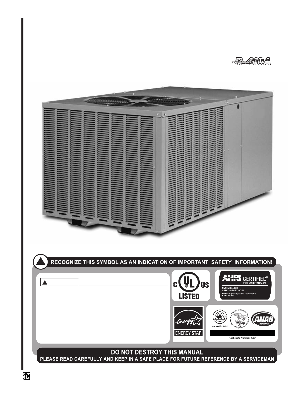
PACKAGE AIR CONDITIONERS
RSNM/RSPM SERIES — (2.0 - 5.0 TONS) FEATURING
NEW INDUSTRY STANDARD R-410A REFRIGERANT:
[ ] INDICATES METRIC CONVERSION
(14 SEER ONLY)
92-21354-58-07
SUPERSEDES 92-21354-58-06
Page 2

TABLE OF CONTENTS
I. Safety Information .................................................................................................3
II. Introduction............................................................................................................4
III. Checking Product Received..................................................................................4
IV. Equipment Protection............................................................................................4
V. Specifications ........................................................................................................4
A. General .............................................................................................................7
B. Major Components............................................................................................7
C.R-410A Refrigerant ...........................................................................................7
1. Specifications of R-410A...............................................................................7
2. Quick Reference Guide for R-410A ..............................................................7
3. Evaporator Coil / TXV ...................................................................................7
4. Tools Required for Installing & Servicing R-410A Models ............................7
VI. Installation .............................................................................................................8
A. General .............................................................................................................8
1. Pre-Installation Check Points........................................................................8
2. Location.........................................................................................................8
B. Outside Slab Installation ...................................................................................8
C.Clearances ........................................................................................................8
D.Rooftop Installation ...........................................................................................8
VII. Ductwork................................................................................................................9
VIII. Filters...................................................................................................................10
IX. Condensate Drain, Indoor Coil............................................................................10
X. Electrical Wiring...................................................................................................10
A. Power Wiring...................................................................................................10
B. Electric Heater Kit Instructions........................................................................11
C.Control Wiring .................................................................................................11
D.Internal Wiring .................................................................................................12
E. Grounding .......................................................................................................12
F. Thermostat......................................................................................................12
XI. Indoor Air Flow Data............................................................................................12
Indoor Airflow Performance............................................................................13-16
XII. Pre-Start Check...................................................................................................17
XIII. Startup.................................................................................................................17
XIV.Operation..................................................................................................................18
A. Control System Operation...............................................................................18
XV. General Data..................................................................................................19-24
XVI. Miscellaneous
Electrical Data................................................................................................25-26
Heater Kit Characteristics...............................................................................27-30
Wiring Diagrams.............................................................................................31-36
Charge Charts................................................................................................37-42
Troubleshooting...................................................................................................43
➤ Installation instructions are updated on a regular basis. This is done as product
changes occur or if new information becomes available. In this publication, an arrow (➤)
denotes changes from the previous edition or additional new material.
2
Page 3
I. SAFETY INFORMATION
WARNING
!
PROPOSITION 65: THIS APPLIANCE CONTAINS FIBERGLASS INSULATION.
RESPIRABLE PARTICLES OF FIBERGLASS ARE KNOWN TO THE STATE OF
CALIFORNIA TO CAUSE CANCER.
WARNING
!
THE MANUFACTURER’S WARRANTY DOES NOT COVER ANY DAMAGE OR
DEFECT TO THE AIR CONDITIONER CAUSED BY THE ATTACHMENT OR USE
OF ANY COMPONENTS, ACCESSORIES OR DEVICES (OTHER THAN THOSE
AUTHORIZED BY THE MANUFACTURER) INTO, ONTO OR IN CONJUNCTION
WITH THE AIR CONDITIONER. YOU SHOULD BE AWARE THAT THE USE OF
UNAUTHORIZED COMPONENTS, ACCESSORIES OR DEVICES MAY
ADVERSELY AFFECT THE OPERATION OF THE AIR CONDITIONER AND MAY
ALSO ENDANGER LIFE AND PROPERTY. THE MANUFACTURER DISCLAIMS
ANY RESPONSIBILITY FOR SUCH LOSS OR INJURY RESULTING FROM THE
USE OF SUCH UNAUTHORIZED COMPONENTS, ACCESSORIES OR DEVICES.
WARNING
!
DISCONNECT ALL POWER TO THE UNIT BEFORE STARTING MAINTENANCE.
FAILURE TO DO SO CAN RESULT IN SEVERE ELECTRICAL SHOCK OR
DEATH.
WARNING
!
UNITS ARE NOT DESIGN CERTIFIED TO BE INSTALLED INSIDE THE STRUCTURE. DOING SO CAN CAUSE INADEQUATE UNIT PERFORMANCE AS WELL
AS PROPERTY DAMAGE AND CARBON MONOXIDE POISONING RESULTING
IN PERSONAL INJURY OR DEATH.
WARNING
!
DO NOT, UNDER ANY CIRCUMSTANCES, CONNECT RETURN DUCTWORK TO
ANY OTHER HEAT PRODUCING DEVICE SUCH AS A FIREPLACE INSERT,
STOVE, ETC. UNAUTHORIZED USE OF SUCH DEVICES MAY RESULT IN FIRE,
CARBON MONOXIDE POISONING, EXPLOSION, PROPERTY DAMAGE,
SEVERE PERSONAL INJURY OR DEATH.
WARNING
!
THE UNIT MUST BE PERMANENTLY GROUNDED. A GROUNDING LUG IS PROVIDED IN THE ELECTRIC HEAT KIT FOR A GROUND WIRE. FAILURE TO
GROUND THIS UNIT CAN RESULT IN FIRE OR ELECTRICAL SHOCK CAUSING
PROPERTY DAMAGE, SEVERE PERSONAL INJURY OR DEATH.
WARNING
!
ONLY ELECTRIC HEATER KITS SUPPLIED BY THIS MANUFACTURER AS
DESCRIBED IN THIS PUBLICATION HAVE BEEN DESIGNED, TESTED, AND
EVALUATED BY A NATIONALLY RECOGNIZED SAFETY TESTING AGENCY
FOR USE WITH THIS UNIT. USE OF ANY OTHER MANUFACTURED ELECTRIC
HEATERS INSTALLED WITHIN THIS UNIT MAY CAUSE HAZARDOUS CONDITIONS RESULTING IN PROPERTY DAMAGE, FIRE, BODILY INJURY OR
DEATH.
WARNING
!
DISCONNECT MAIN ELECTRICAL POWER TO THE UNIT BEFORE ATTEMPTING
TO CHANGE BLOWER SPEEDS. FAILURE TO DO SO MAY RESULT IN ELECTRICAL SHOCK OR SEVERE PERSONAL INJURY OR DEATH.
!
CAUTION
R-410A systems operate at higher pressures than R-22 systems. Do not use
R-22 service equipment or components on R-410A equipment.
3
Page 4
WARNING
!
IMPORTANT: ALL MANUFACTURER PRODUCTS MEET CURRENT
FEDERAL OSHA GUIDELINES FOR
SAFETY. CALIFORNIA
PROPOSITION 65 WARNINGS ARE
REQUIRED FOR CERTAIN PRODUCTS, WHICH ARE NOT COVERED
BY THE OSHA STANDARDS.
CALIFORNIA'S PROPOSITION 65
REQUIRES WARNINGS FOR PRODUCTS SOLD IN CALIFORNIA THAT
CONTAIN, OR PRODUCE, ANY OF
OVER 600 LISTED CHEMICALS
KNOWN TO THE STATE OF
CALIFORNIA TO CAUSE CANCER
OR BIRTH DEFECTS SUCH AS
FIBERGLASS INSULATION, LEAD
IN BRASS, AND COMBUSTION
PRODUCTS FROM NATURAL GAS.
ALL “NEW EQUIPMENT” SHIPPED
FOR SALE IN CALIFORNIA WILL
HAVE LABELS STATING THAT THE
PRODUCT CONTAINS AND/OR
PRODUCES PROPOSITION 65
CHEMICALS. ALTHOUGH WE HAVE
NOT CHANGED OUR PROCESSES,
HAVING THE SAME LABEL ON ALL
OUR PRODUCTS FACILITATES
MANUFACTURING AND SHIPPING.
WE CANNOT ALWAYS KNOW
“WHEN, OR IF” PRODUCTS WILL
BE SOLD IN THE CALIFORNIA
MARKET.
YOU MAY RECEIVE INQUIRIES
FROM CUSTOMERS ABOUT CHEMICALS FOUND IN, OR PRODUCED
BY, SOME OF OUR HEATING AND
AIR-CONDITIONING EQUIPMENT,
OR FOUND IN NATURAL GAS USED
WITH SOME OF OUR PRODUCTS.
LISTED BELOW ARE THOSE CHEMICALS AND SUBSTANCES COMMONLY ASSOCIATED WITH SIMILAR EQUIPMENT IN OUR INDUSTRY AND OTHER MANUFACTURERS.
• GLASS WOOL (FIBERGLASS)
INSULATION
• CARBON MONOXIDE (CO)
• FORMALDEHYDE
• BENZENE
MORE DETAILS ARE AVAILABLE
AT THE WEBSITES FOR OSHA
(OCCUPATIONAL SAFETY AND
HEALTH ADMINISTRATION), AT
WWW.OSHA.GOV
OF CALIFORNIA'S OEHHA (OFFICE
OF ENVIRONMENTAL HEALTH
HAZARD ASSESSMENT), AT
WWW.OEHHA.ORG.
EDUCATION IS IMPORTANT SINCE
THE CHEMICALS AND SUBSTANCES ON THE LIST ARE
FOUND IN OUR DAILY LIVES. MOST
CONSUMERS ARE AWARE THAT
PRODUCTS PRESENT SAFETY AND
HEALTH RISKS, WHEN IMPROPERLY USED, HANDLED AND MAINTAINED.
AND THE STATE
CONSUMER
II. INTRODUCTION
This booklet contains the installation and operating instructions for your self-contained
air conditioner. There are a few precautions that should be taken to derive maximum
satisfaction from it. Improper installation can result in unsatisfactory operation or dangerous conditions.
Read this booklet and any instructions packaged with separate equipment required to
make up the system prior to installation. Give this booklet to the owner and explain its
provisions. The owner should retain this booklet for future reference.
III. CHECKING PRODUCT RECEIVED
Upon receiving the unit, inspect it for any damage from shipment. Claims for damage,
either shipping or concealed, should be filed immediately with the shipping company.
Check the unit model number, electrical characteristics, and accessories to determine if
they are correct.
IV. EQUIPMENT PROTECTION FROM THE
ENVIRONMENT
The metal parts of this unit may be subject to rust or deterioration in adverse environ men tal conditions. This oxidation could shorten the equipment’s useful life. Salt spray,
fog or mist in seacoast areas, sulphur or chlorine from lawn watering systems, and various chemical contaminants from industries such as paper mills and petroleum refineries
are especially corrosive.
If the unit is to be installed in an area where contaminants are likely to be a problem, special attention should be given to the equipment location and exposure.
1. Avoid having lawn sprinkler heads spray directly on the unit cabinet.
2. In coastal areas, locate the unit on the side of the building away from the waterfront.
3. Shielding provided by a fence or shrubs may give some protection.
4. Elevating the unit off its slab or base enough to allow air circulation will help avoid
holding water against the basepan.
Regular maintenance will reduce the buildup of contaminants and help to protect
the unit’s finish.
WARNING
!
DISCONNECT ALL POWER TO THE UNIT BEFORE STARTING MAINTENANCE.
FAILURE TO DO SO CAN RESULT IN SEVERE ELECTRICAL SHOCK OR
DEATH.
1. Frequent washing of the cabinet, fan blade and coil with fresh water will remove
most of the salt or other contaminants that build up on the unit.
2. Regular cleaning and waxing of the cabinet with an automobile polish will provide
some protection.
3. A liquid cleaner may be used several times a year to remove matter that will not
wash off with water.
Several different types of protective coatings are offered in some areas. These coatings
may provide some benefit, but the effectiveness of such coating materials cannot be verified by the equipment manufacturer.
The best protection is frequent cleaning, maintenance and minimal exposure to
contaminants.
V. SPECIFICATIONS
Suitable for use in mobile homes, manufactured housing, and conventionally constructed residential and commercial buildings where horizontally-ducted systems are preferred.
4
Page 5
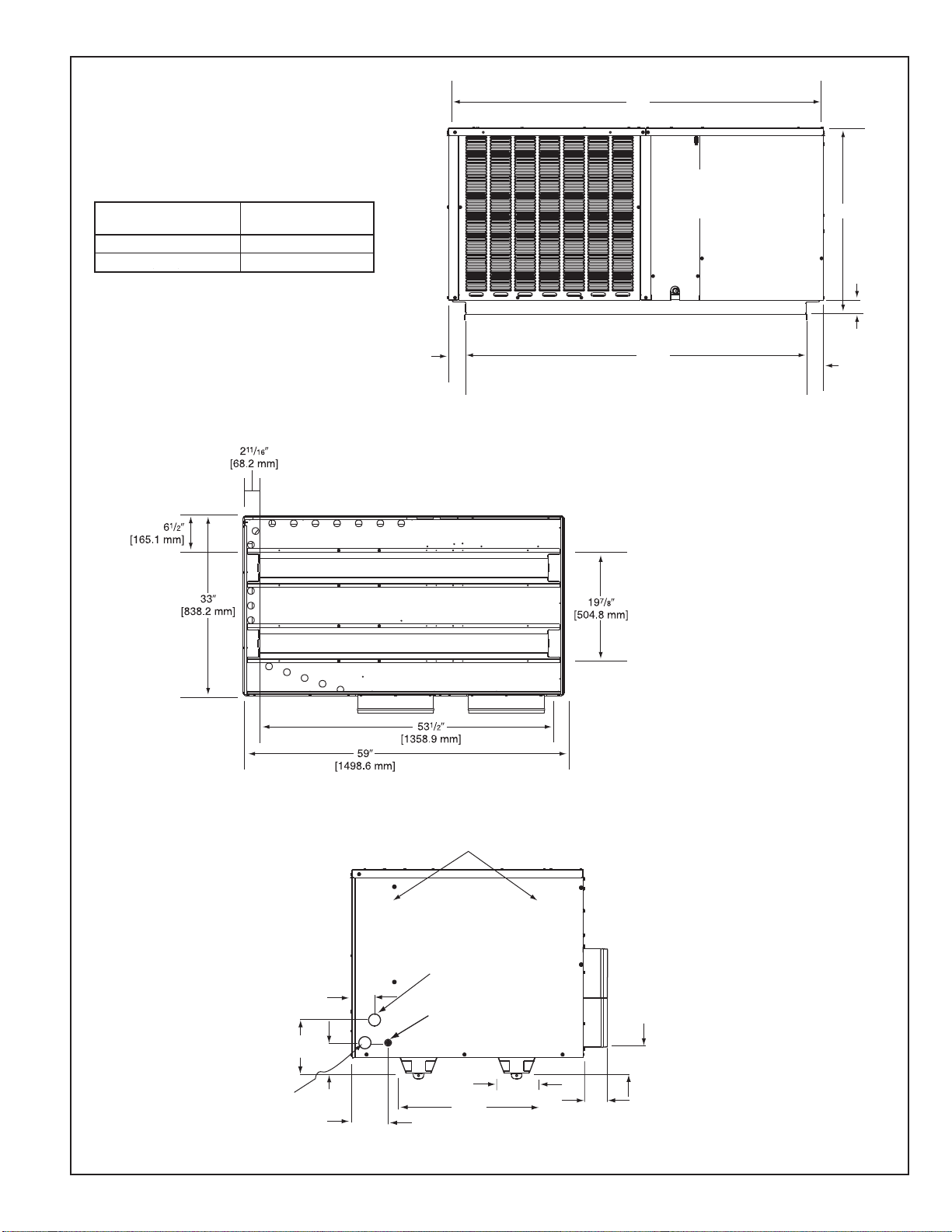
FIGURE 1
Model
024, 030, 036
042, 048, 060
Height “A”
29 1/8"
37 1/8"
211/16"
[266.7 mm]
59"
[1498.6 mm]
53
1
/2"
[1358.9 mm]
3
1
/16"
[77.7 mm]
A
CONTROL
BOX ACCESS
211/16"
[266.7 mm]
CONDENSATE
DRAIN
PAN
ACCESS
PRIMARY
HIGH VOLTAGE
ENTRANCE
1
23
/32" [43.7 mm]
4
13
/32"
[111.8 mm]
5
9
/64"
[130.5 mm]
19
7
/8"
[505 mm]
57/8"
[149.5 mm]
3
1
/2"
[88.9 mm]
3
3
/4"
[95.3 mm]
721/32"
[194.3 mm]
313/64"
[81.2 mm]
AUXILIARY
HIGH VOLTAGE
ENTRANCE
1
23
/32" [43.7 mm]
LOW VOLTAGE
ENTRANCE
7
/8" [22.2 mm]
RECOMMENDED UNIT
DISCONNECT LOCATION
UNIT DIMENSIONS AND ACCESS LOCATIONS
024, 030, 036, 042, 043
048, 060
FRONT VIEW
BOTTOM VIEW
ELECTRICAL CONNECTIONS
5
Page 6
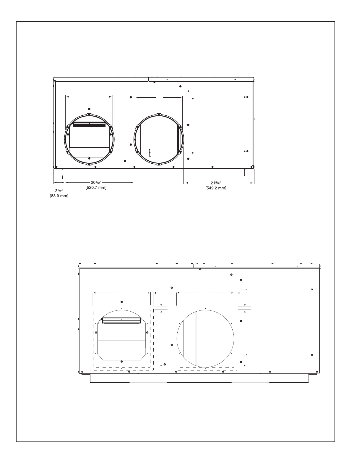
DUCT CONNECTIONS
14.00"
[355.6 mm]
14.00"
[355.6 mm]
[19.05 mm]
"
3
4
/
14.00"
[355.6 mm]
14.00"
[355.6 mm]
[19.05 mm]
3
4
/
IMPORTANT: DO NOT SCREW OR DRILL OUTSIDE THE DESIGNATED AREAS.
14"
[355.6 mm]
14"
[355.6 mm]
ROUND DUCT CONNECTIONS
IN THIS AREA
DO NOT DRILL OR INSTALL SCREWS
SQUARE DUCT CONNECTIONS
IMPORTANT: This product is designed to be operated with 14 round supply and
return air ducts. Square ducts may be used, provided that a minimum length of 24
of round duct is used on the supply and return connections. This requirement is
necessary to maintain blower performance.
6
Page 7
WARNING
!
THE MANUFACTURER’S WARRANTY DOES NOT COVER ANY DAMAGE OR DEFECT TO THE AIR CONDITIONER CAUSED BY THE
ATTACHMENT OR USE OF ANY
COMPONENTS, ACCESSORIES OR
DEVICES (OTHER THAN THOSE
AUTHORIZED BY THE MANUFACTURER) INTO, ONTO OR IN CONJUNCTION WITH THE AIR CONDITIONER. YOU SHOULD BE AWARE
THAT THE USE OF UNAUTHORIZED COMPONENTS, ACCESSORIES OR DEVICES MAY
ADVERSELY AFFECT THE OPERATION OF THE AIR CONDITIONER
AND MAY ALSO ENDANGER LIFE
AND PROPERTY. THE MANUFACTURER DISCLAIMS ANY RESPONSIBILITY FOR SUCH LOSS OR
INJURY RESULTING FROM THE
USE OF SUCH UNAUTHORIZED
COMPONENTS, ACCESSORIES OR
DEVICES.
A. GENERAL
The Packaged Air Conditioner is available without heat or with 5, 7, 10, 15, or 20 kW
electric heat. Cooling capacities of 2, 2
available.
The units are weatherized for mounting outside of the building.
The information on the rating plate is in compliance with the FTC and DOE rating for sin-
gle phase units.
1
⁄2, 3, 31⁄2 , 4 and 5 nominal tons of cooling are
B. MAJOR COMPONENTS
The unit includes a hermetically-sealed refrigerating system (consisting of a compressor,
condenser coil, evaporator coil with refrigerant metering device), a circulation air blower,
a condenser fan, and all necessary internal electrical wiring. The cooling system of these
units is factory-evacuated, charged and performance tested. Refrigerant amount and
type are indicated on rating plate.
C. R-410A REFRIGERANT
All units are factory charged with R-410A refrigerant.
1. Specification of R-410A:
Application: R-410A is not a drop-in replacement for R-22; equipment designs must
accommodate its higher pressures. It cannot be retrofitted into R-22 units.
Pressure: The pressure of R-410A is approximately 60% (1.6 times) greater than R-22.
Recovery and recycle equipment, pumps, hoses and the like need to have design pressure ratings appropriate for R-410A. Manifold sets need to range up to 800 psig high-
side and 250 psig low-side with a 550 psig low-side retard. Hoses need to have a service pressure rating of 800 psig. Recovery cylinders need to have a 400 psig service
pressure rating. DOT 4BA400 or DOT BW400.
Combustibility: At pressures above 1 atmosphere, mixture of R-410A and air can
become combustible. R-410A and air should never be mixed in tanks or supply lines, or
be allowed to accumulate in storage tanks. Leak checking should never be done with a
mixture of R-410A and air. Leak checking can be performed safely with nitrogen or a
mixture of R-410A and nitrogen.
2. Quick Reference Guide For R-410A
• R-410A refrigerant operates at approximately 60% higher pressure (1.6 times) than R-
22. Ensure that servicing equipment is designed to operate with R-410A.
• R-410A refrigerant cylinders are pink.
• R-410A, as with other HFC’s is only compatible with POE oils.
• Vacuum pumps will not remove moisture from POE oil.
• R-410A systems are to be charged with liquid refrigerants. Prior to March 1999, R410A refrigerant cylinders had a dip tube. These cylinders should be kept upright for
equipment charging. Post March 1999 cylinders do not have a dip tube and should
be inverted to ensure liquid charging of the equipment.
• Do not install a suction line filter drier in the liquid line.
• A liquid line filter drier is standard on every unit.
• Desiccant (drying agent) must be compatible for POE oils and R-410A.
3. Evaporator Coil / TXV
The thermostatic expansion valve is specifically designed to operate with R-410A. DO
NOT use an R-22 TXV. The existing evaporator must be replaced with the factory
specified TXV evaporator specifically designed for R-410A.
4. Tools Required For Installing & Servicing R-410A Models
Manifold Sets:
-Up to 800 PSIG High side
-Up to 250 PSIG Low Side
-550 PSIG Low Side Retard
Manifold Hoses:
-Service Pressure Rating of 800 PSIG
7
Page 8

Recovery Cylinders:
-400 PSIG Pressure Rating
-Dept. of Transportation 4BA400 or BW400
!
CAUTION
R-410A systems operate at higher pressures than R-22 systems. Do not use
R-22 service equipment or components on R-410A equipment.
VI. INSTALLATION
A. GENERAL
1. PRE-INSTALLATION CHECK-POINTS
Before attempting any installation, the following points should be carefully consid-
ered:
a. Structural strength of supporting members.
(rooftop installation)
b. Clearances and provision for servicing.
c. Power supply and wiring.
d. Air duct connections.
e. Drain facilities and connections.
f. Location for minimum noise.
2. LOCATION
These units are designed for outdoor installations. They can be mounted on a
slab or rooftop. They are not to be installed within any part of a structure such as
an attic, crawl space, closet, or any other place where condenser air flow is
restricted or other than outdoor ambient conditions prevail. Since the application
of the units is of the outdoor type, it is important to consult your local code authorities at the time the first installation is made.
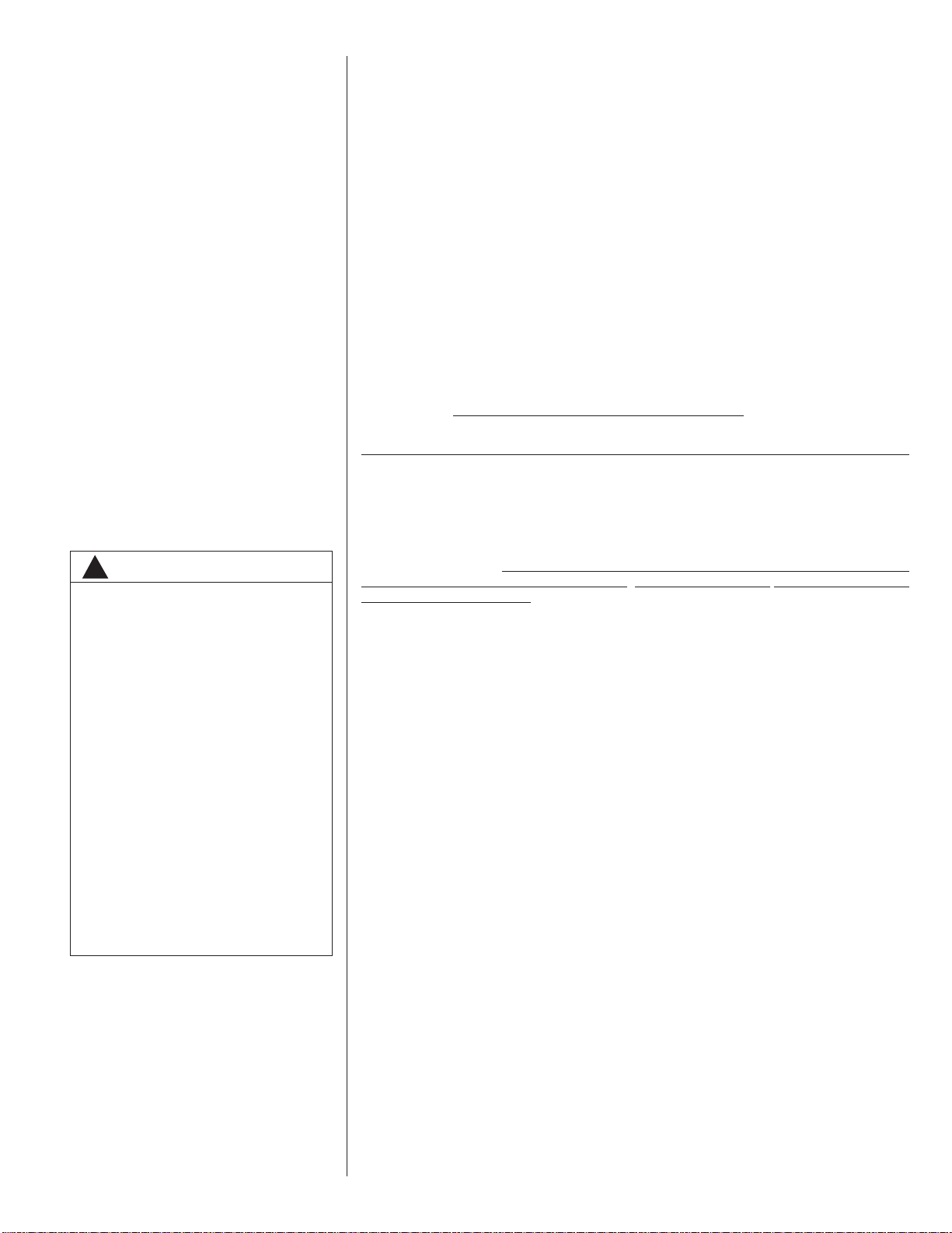
B. OUTSIDE SLAB INSTALLATION
(Typical outdoor slab installations are shown in Figure 2.)
1. Select a location where external water drainage cannot collect around the unit.
2. Provide a level concrete slab extending 3" beyond all four sides of the unit. The
slab should be sufficient above grade to prevent ground water from entering the
unit.
IMPORTANT: To prevent transmission of noise or vibration, slab should not be
connected to building structure.
3. The location of the unit should be such as to provide proper access for inspection
and servicing.
4. Locate unit where operating sounds will not disturb owner or neighbors.
5. Locate unit so roof runoff water does not pour directly on the unit. Provide gutter
or other shielding at roof level. Do not locate unit in an area where excessive
snow drifting may occur or accumulate.
C. CLEARANCES
The following minimum clearances must be observed for proper unit performance
and serviceability.
1. Provide 30" minimum clearance at the front and 18" on the right side of the unit
for service access. Provide 12" minimum clearance on the left side of the unit for
air inlet.
2. Provide 60" minimum clearance from top of unit.
3. Unit is design certified for application on combustible flooring with 0" minimum
clearance.
4. See Figure 2 for illustration of minimum installation-service clearances.
D. ROOFTOP INSTALLATION
1. Before locating the unit on the roof, make sure that the strength of the roof and
beams is adequate at that point to support the weight involved. (See specification
sheet for weight of unit.) This is very important and user’s responsibility.
2. The unit should be placed on a solid and level platform of adequate strength.
8
Page 9
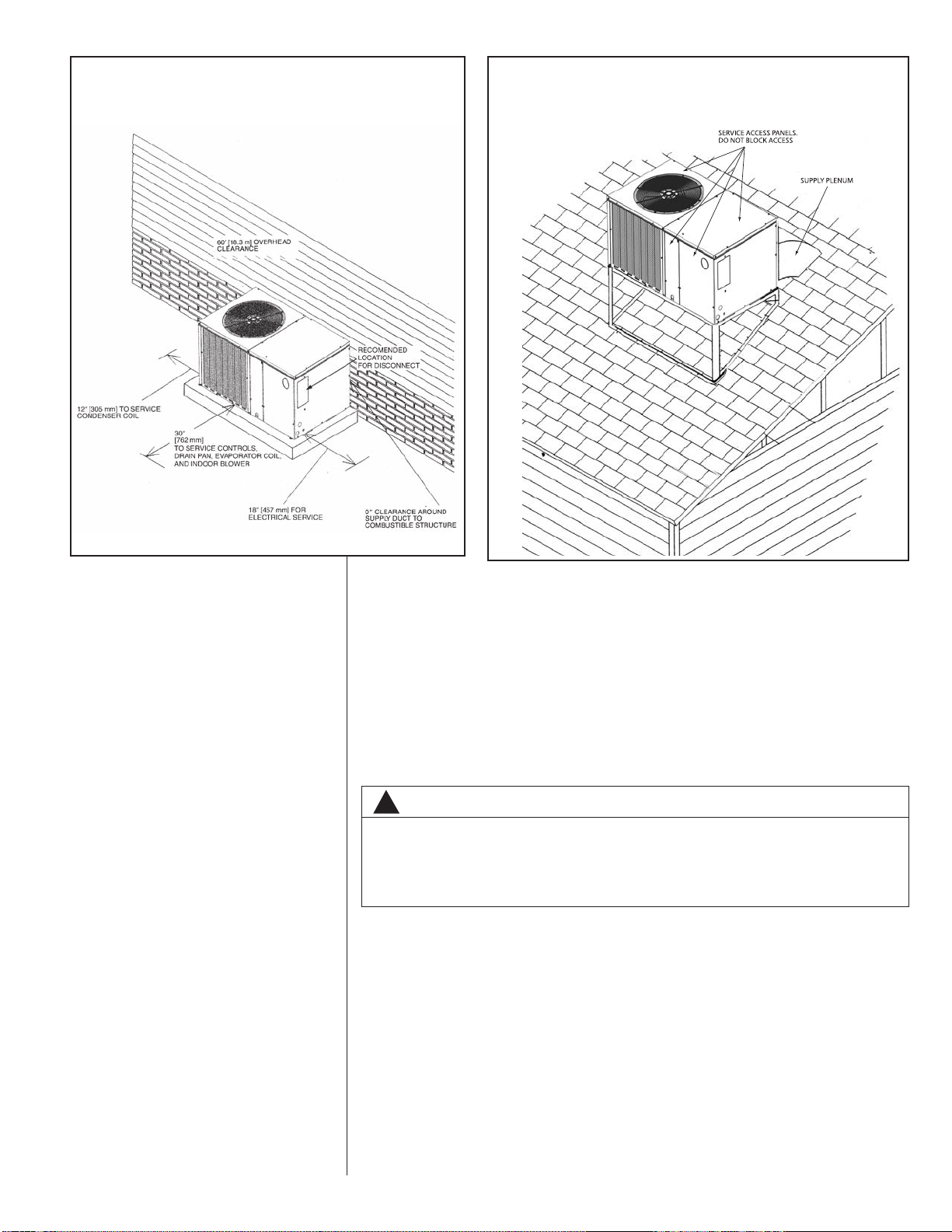
FIGURE 2
PACKAGE AIR CONDITIONER
OUTSIDE SLAB INSTALLATION, BASEMENT OR
CRAWL SPACE DISTRIBUTION SYSTEM
FIGURE 3
PACKAGE AIR CONDITIONER
PITCHED ROOFTOP INSTALLATION, ATTIC
OR DROP CEILING DISTRIBUTING SYSTEM.
MUST BE MOUNTED LEVEL.
3. The location of the unit on the roof should be such as to provide proper access for
inspection and servicing (Figure 3).
IMPORTANT: If unit will not be put into service immediately, cover supply and return
openings to prevent excessive condensation.
VII.DUCTWORK
Ductwork should be fabricated by the installing contractor in accordance with local codes
and NFPA90A. Industry manuals may be used as a guide when sizing and designing the
duct system - contact Air Conditioning Contractors of America, 1513 16th St. N.W.,
Washington, D.C. 20036.
WARNING
!
DO NOT, UNDER ANY CIRCUMSTANCES, CONNECT RETURN DUCTWORK TO
ANY OTHER HEAT PRODUCING DEVICE SUCH AS A FIREPLACE INSERT,
STOVE, ETC. UNAUTHORIZED USE OF SUCH DEVICES MAY RESULT IN FIRE,
CARBON MONOXIDE POISONING, EXPLOSION, PROPERTY DAMAGE,
SEVERE PERSONAL INJURY OR DEATH.
Place the unit as close to the space to be air conditioned as possible allowing clearance
dimensions as indicated. Run ducts as directly as possible to supply and return outlets.
Use of non-flammable waterproof flexible connectors on both supply and return connections at the unit to reduce noise transmission is recommended.
It is preferable to install the unit on the roof of the structure if the registers or diffusers
are located on the wall or in the ceiling. Consider a slab installation when the registers
are low on a wall or in the floor.
On ductwork exposed to outside air conditions of temperature and humidity, use a minimum of 2" of insulation and a vapor barrier. Distribution system in attic, furred space or
crawl space should be insulated with at least 2" of insulation with vapor barrier. One-half
to 1" thickness of insulation is usually sufficient for ductwork inside the air conditioned
space.
Provide balancing dampers for each branch duct in the supply system. Properly support
the ductwork from the structure.
9
Page 10
VIII.FILTERS
Filters are not provided with this unit. They must be supplied and installed in the return
air duct by the installer. A field installed filter grille is recommended for easy and convenient access to the filters for periodic inspection and cleaning. Filters must have adequate face area for the rated air quantity of the unit. See General Database for recommended filter size.
IX. CONDENSATE DRAIN
The indoor coil condensate drain ends with a PVC stub. A trap is provided in for proper
condensate drainage and to prevent debris from being drawn into the unit. Do not connect drain to closed sewer line. It is not recommended that a PVC cement or other permanent installation be used so that the drain line and/or drain pan can be easily cleaned
in the future. The drain trap is located in the control box during shipping. To install, slide
clear plastic tube over drain pan connection. The white PVC trap can be oriented as
required by installation.
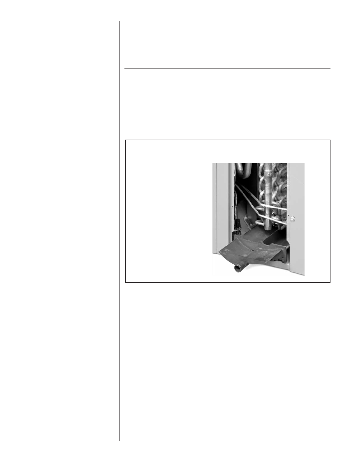
FIGURE 4
REMOVABLE CONDENSATE DRAIN PAN AND REMOVAL PROCEDURE
A small side panel grants
access to a removable,
sloped drain pan (A), which
helps to ensure indoor air
quality (IAQ) throughout
the life of the unit. A drain
trap (B) assembly is provided for convenience.
10
X. ELECTRICAL WIRING
Field wiring must comply with the National Electrical Code* and applicable local codes.
*C.E.C. in Canada
A. POWER WIRING
1. It is important that proper electrical power is available at the unit. Voltage should
not vary more than 10% from that stamped on the unit rating plate. On three
phase units, phases must be balanced within 3%.
2. Install a branch circuit disconnect within sight of the unit and of adequate size to
handle the starting current. (See Heater Kit Tables.)
3. For branch circuit wiring (main power supply to unit disconnect), the minimum
wire size can be determined from the National Electrical Code or Canadian
Electrical Code or nameplate or from Heater Kit Tables.
4. This unit supports both single and dual point electrical connection for unit and
electric heat accessory.
5. Power wiring must be run in grounded rain-tight conduit.
Page 11

WARNING
!
TURN OFF ELECTRIC POWER AT
THE FUSE BOX OR SERVICE
PANEL BEFORE MAKING ANY
ELECTRICAL CONNECTIONS.
ALSO, THE GROUND CONNECTION
MUST BE COMPLETED BEFORE
MAKING LINE VOLTAGE CONNECTIONS. FAILURE TO DO SO CAN
RESULT IN ELECTRICAL SHOCK,
SEVERE PERSONAL INJURY OR
DEATH.
B. POWER WIRING AND ELECTRIC HEATER KIT INSTRUCTIONS
1. Turn off power to unit.
2. Remove control box access panel.
3. Remove unit indoor section top cover.
4. Remove wire notch cover from control bulkhead and discard. Retain screw.
5. Remove heater element cover plate from blower outlet opening and discard. Retain
screws.
6. Mount heater fuse block assembly in location indicated with the three included
screws.
7. Route wire harness assembly through wire notch in control bulkhead and mount element assembly in blower outlet opening with screws previously retained.
8. Center wire routing plate over notch in blower bulkhead and secure with screw previously retained.
9. Route and tie wiring as shown in Figure 5. Wiring must not contact moving parts or
uninsulated electrical connections.
10. Replace unit indoor top cover.
11. Connect power and control wiring as indicated below:
a. Single-point wiring: Connect high voltage field power leads to heater kit fuse
block and connect included unit power pigtails from heater kit fuse block to unit
contactor L1 and L3 connections. Connect ground lead to ground lug on heater kit
fuse block.
b. Dual-circuit wiring: Remove unit power pigtails from heater kit fuse block and
discard. Connect one set of high voltage field power circuit leads to the heater kit
fuse block and connect ground lead to ground lug on heater kit fuse block.
Connect the second set of high voltage field power leads to L1 and L3 on the unit
contactor. Connect ground lead to ground lug on control box bulkhead.
c. Connect heater kit control plug to receptacle in control box.
12. Replace control box access panel.
13. Restore power to unit and verify proper unit and heater kit operation.
C. CONTROL WIRING (Class II)
1. Do not run low voltage wiring in conduit with power wiring.
2. Control wiring is routed through the 7/8" hole corner adjacent to the control box.
See Electrical Connections, Figure 1. Use a minimum #18 AWG thermostat wire.
For wire lengths exceeding 50', use #16 AWG thermostat wire. The low voltage
wires are connected to the unit pigtails which are supplied with the unit in the low
voltage connection box located within the unit control box. See Figure 5.
3. Figure 6 shows representative low voltage connection diagrams. Read your ther-
mostat installation instructions for any special requirements for your specific thermostat.
NOTE — Units installed in Canada require that an outdoor thermostat (30,000
min. cycles of endurance) be installed and be wired with C.E.C. Class I wiring.
11
Page 12
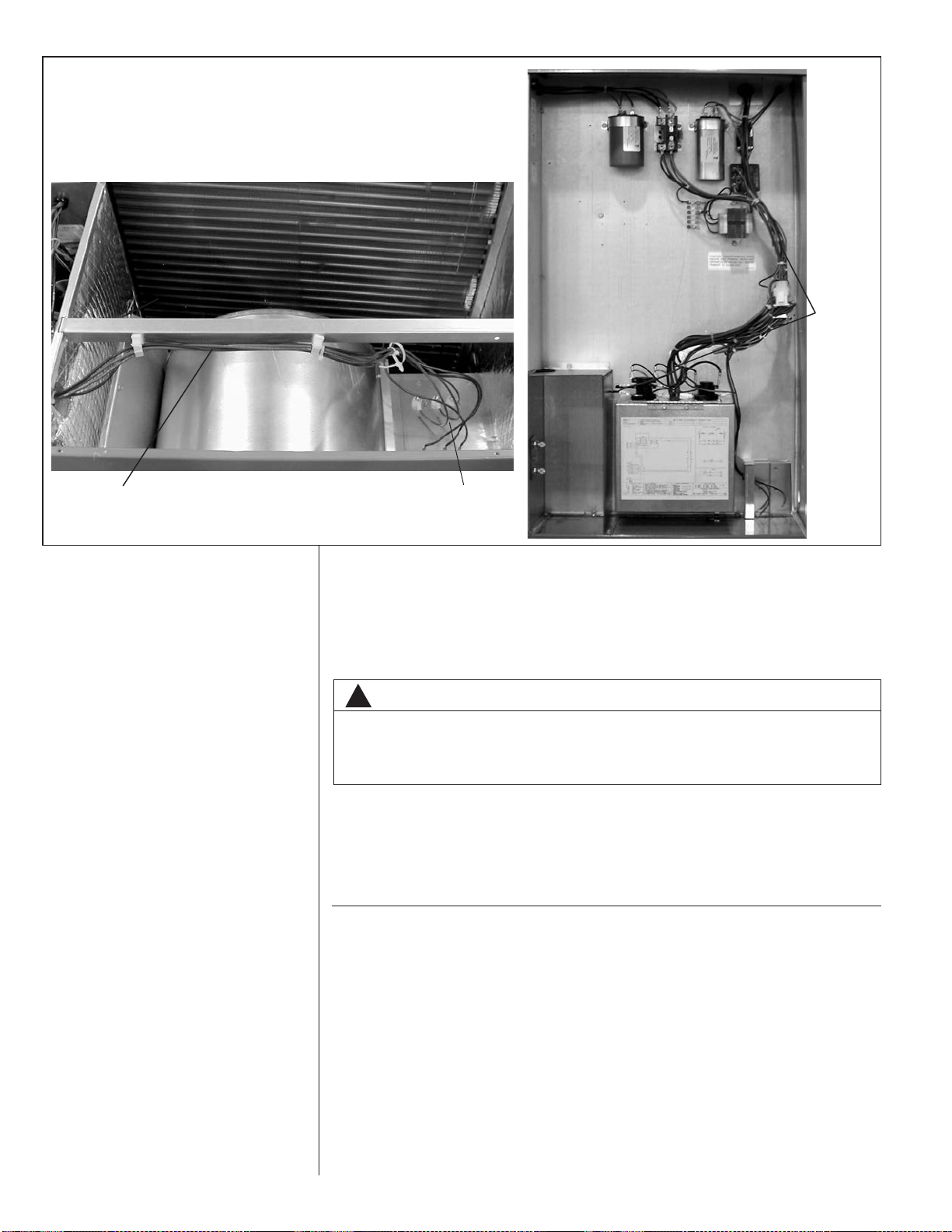
FIGURE 5
HEATER KIT INSTALLATION
HEATER
KIT
WIRING
RECOMMENDED
WIRING
HEATER
ELEMENTS
D. INTERNAL WIRING
1. A diagram of the internal wiring of this unit is located on the electrical control box
cover. If any of the original wire as supplied with the appliance must be replaced,
the wire gauge and insulation must be the same as original wiring.
E. GROUNDING
WARNING
!
THE UNIT MUST BE PERMANENTLY GROUNDED. A GROUNDING LUG IS
PROVIDED. FAILURE TO GROUND THIS UNIT CAN RESULT IN FIRE OR ELECTRICAL SHOCK CAUSING PROPERTY DAMAGE, SEVERE PERSONAL INJURY
OR DEATH.
F. THERMOSTAT
Mount the thermostat on an inside wall about five feet above the floor in a location
where it will not be affected by unconditioned air, sun, or drafts from open doors or
other sources. READ installation instructions in air conditioner thermostat package
CAREFULLY because each has some different wiring requirements.
XI. INDOOR AIR FLOW DATA
All 208/230 volt units are equipped with multi-speed indoor blower motors. Each unit is
shipped factory wired for the proper speed at a normal external static. See Airflow
Performance Table for blower performance.
12
Page 13
CFM Air Delivery/RPM/Watts-230 Volts
External Static Pressure-Inches W.C.
0.10 0.20 0.30 0.40 0.50 0.60 0.70 0.80 0.90 1.00
CFM 827 811 782 740 684 614 531 435
10x9 Low RPM 450 533 626 742 799 894 932 985
2.0 Low 700 / 900 1/4 Watts 278 273 269 254 244 227 216 198
2 Speed CFM 1230 1223 1216 1211 1187 1125 1020 874 696 504
(PSC Motor) High RPM 575 643 703 767 819 877 976 1001 1072 1092
Watts 479 468 455 448 431 416 357 341 279 259
CFM 1032 1030 1014 979 923 843 735 596 423
10x9 Low RPM 533 570 659 746 795 863 934 1019 1050
2.5 Low 875 / 1125 1/3 Watts 336 331 326 314 303 280 271 227 210
2 Speed CFM 1312 1301 1292 1276 1246 1196 1117 1003 845
(PSC Motor) High RPM 592 646 712 768 824 883 933 1012 1035
Watts 482 473 466 454 433 421 401 349 329
CFM 1261 1253 1225 1177 1110 1023 915 788 641
10x9 Low RPM 648 705 754 802 854 896 985 1008 1041
3.0 Low 1050 / 1350 1/2 Watts 398 395 387 391 370 361 323 310 300
2 Speed CFM 2068 2008 1957 1905 1841 1753 1629 1458 1228 929
(PSC Motor) High RPM 850 883 917 946 972 999 1028 1049 1091 1108
Watts 826 806 784 762 734 702 658 626 546 512
CFM 1431 1394 1348 1302 1258 1208 1140 1030 849 557
11x9 Low RPM 540 579 633 686 724 776 831 868 1035 1076
3.5 Low 1225 / 1575 1/2 Watts 482 479 477 470 459 453 437 423 335 292
2 Speed CFM 1960 1936 1903 1859 1806 1742 1669 1585 1491 1387
(PSC Motor) High RPM 703 727 750 780 809 846 877 910 940 975
Watts 783 782 776 759 750 729 712 686 656 625
CFM 1674 1638 1595 1547 1492 1432 1365 1293 1214 1129.1
11x9 Low RPM 576 618 668 708 753 789 832 874 915 954
4.0 Low 1400 / 1800 3/4 Watts 575 563 556 549 544 532 522 503 483 465
2 Speed CFM 1996 1976 1947 1909 1863 1808 1744 1671 1590 1500
(PSC Motor) High RPM 680 722 752 781 807 833 867 912 936 973
Watts 799 787 784 760 753 749 730 699 693 652
CFM 2044 2017 1983 1941 1892 1836 1773 1702 1623 1537
11x9 Low RPM 689 723 756 798 822 855 889 924 951 988
5.0 Low 1750 / 2250 3/4 Watts 886 870 865 849 831 817 799 782 755 726
2 Speed CFM 2693 2654 2606 2549 2483 2408 2323 2230 2127 2015
(PSC Motor) High RPM 876 897 915 938 956 975 996 1009 1025 1044
Watts 1438 1427 1399 1368 1340 1312 1274 1228 1192 1146
Nominal
Cooling
Capacity
Tons
Motor Speed
From Factor
y
Blower Size/
Motor HP
#
of S
p
eeds
Motor
S
p
eed
Manufacturer
Recommended
Air
Flow Range
Min / Max
)
CFM
-
–––
–––
–––––––––
INDOOR AIRFLOW PERFORMANCE - RSNM - 230 VOLTS
&
13
Page 14
CFM Air Delivery/RPM/Watts-208 Volts
External Static Pressure-Inches W.C.
0.10 0.20 0.30 0.40 0.50 0.60 0.70 0.80 0.90
CFM 723 692 654 609 556 496 428
10x9 Low RPM 443 528 651 710 819 863 914
2.0 Low 700 / 900 1/4 Watts 230 222 219 214 202 196 184
2 Speed CFM 1062 1062 1058 1043 1013 962 884 774 627
(PSC Motor) High RPM 528 618 674 735 812 895 936 985 1055
Watts 396 393 384 376 361 335 318 297 244
CFM 923 904 874 832 774 698 602 483
10x9 Low RPM 498 543 648 728 806 853 947 989
2.5 Low 875 / 1125 1/3 Watts 280 278 268 259 252 243 219 201
2 Speed CFM 1164 1154 1143 1124 1090 1034 948 826 660
(PSC Motor) High RPM 526 596 670 744 803 864 945 971 1051
Watts 401 398 388 379 371 350 322 310 259
CFM 1145 1142 1118 1073 1006 918
10x9 Low RPM 556 645 703 769 828 909
3.0 Low 1050 / 1350 1/2 Watts 346 340 335 326 321 298
2 Speed CFM 1884 1850 1815 1772 1712 1630 1516 1363 1164
(PSC Motor) High RPM 791 834 871 912 946 975 1004 1032 1083
Watts 704 694 675 655 638 606 581 548 464
CFM 1279 1237 1196 1151 1098 1032 950 846 717.13
11x9 Low RPM 490 539 598 653 709 772 811 887 928
3.5 Low 1225 / 1575 1/2 Watts 401 400 393 391 381 373 364 343 329
2 Speed CFM 1751 1729 1698 1658 1608 1549 1481 1404 1317
(PSC Motor) High RPM 640 668 706 734 781 813 851 888 937
Watts 660 658 651 644 628 617 603 581 557
CFM 1400 1393 1373 1337 1288 1225 1147 1055 949
11x9 Low RPM 536 578 623 677 718 782 830 863 902
4.0 Low 1400 / 1800 3/4 Watts 471 466 458 455 453 442 429 420 403
2 Speed CFM 1786 1764 1734 1695 1649 1595 1532 1462 1384
(PSC Motor) High RPM 618 643 684 726 757 805 841 883 924
Watts 665 660 651 646 638 626 612 596 573
CFM 1848 1821 1785 1742 1690 1630 1562 1486 1402
11x9 Low RPM 660 685 722 755 795 836 867 904 940
5.0 Low 1750 / 2250 3/4 Watts 731 725 720 707 698 680 665 651 623
2 Speed CFM 2444 2420 2384 2337 2278 2208 2127 2034 1930
(PSC Motor) High RPM 829 838 863 885 914 936 958 983 1003
Watts 1225 1218 1197 1191 1160 1135 1105 1068 1035
Nominal
Cooling
Capacity
Tons
Motor Speed
From Factor
y
Blower Size/
Motor HP
#
of S
p
eeds
Motor
S
p
eed
Manufacturer
Recommended
Air-
Flow Range
(
Min / Max
)
CFM
–––––
–
–––
––––––
–––
INDOOR AIRFLOW PERFORMANCE - RSNM - 208 VOLTS
&
14
Page 15

CFM Air Delivery/RPM/Watts-230 Volts
External Static Pressure-Inches W.C.
0.10 0.20 0.30 0.40 0.50 0.60 0.70 0.80 0.90 1.00
CFM 939 877 816 754 693 631 570 508 447
10x9 RPM 585 601 655 744 809 860 915 1001 1043
1/4 Watts 131 116 97 110 121 126 136 149 152
2 Speed CFM 1240 1184 1127 1071 1014 958 901 845 788 732
(X-13 Motor) RPM 607 634 698 761 815 880 946 989 1038 1091
Watts 161 145 159 173 182 196 210 220 231 237
CFM 1169 1109 1049 988 928 868 807 747 687 626
10x9 RPM 603 619 693 756 809 893 942 989 1034 1076
1/3 Watts 144 130 138 151 159 174 185 195 199 209
2 Speed CFM 1365 1316 1266 1217 1168 1119 1069 1020 971 922
(X-13 Motor) RPM 631 677 732 784 843 894 942 1035 1077 1118
Watts 177 190 204 218 234 247 256 279 289 294
CFM 1328 1280 1231 1183 1135 1086 1038 990 941 893
10x9 RPM 648 697 752 807 857 903 989 1036 1077 1114
1/2 Watts 178 191 206 220 233 246 265 277 286 291
2 Speed CFM 1510 1464 1418 1373 1327 1281 1235 1190 1144 1098
(X-13 Motor) RPM 707 743 792 841 890 5021 981 1031 1114 1151
Watts 248 261 277 292 307 322 334 348 366 358
CFM 1542 1490 1438 1386 1335 1283 1231 1180 1128 1076
11x9 RPM 598 617 662 714 758 800 849 876 913 951
1/2 Watts 244 231 237 254 270 285 304 313 326 340
2 Speed CFM 1740 1695 1649 1604 1558 1513 1467 1422 1376 1331
(X-13 Motor) RPM 632 665 709 749 797 833 879 917 951 981
Watts 295 311 331 350 371 386 409 426 440 454
CFM 1701 1655 1609 1563 1517 1471 1425 1379 1333 1287
11x9 RPM 624 648 696 743 787 826 863 895 934 970
3/4 Watts 280 287 309 328 347 363 380 392 410 426
2 Speed CFM 1921 1878 1835 1792 1749 1706 1663 1620 1577 1534
(X-13 Motor) RPM 678 706 738 776 816 865 899 932 967 994
Watts 385 400 416 439 458 484 501 517 537 550
CFM 1986 1945 1905 1864 1823 1782 1741 1700 1659 1618
11x9
RPM 731 759 792 832 871 909 943 979 1014 1055
3/4
Watts 446 458 477 499 521 543 562 582 600 621
2 Speed
CFM 2229 2190 2152 2114 2075 2037 1999 1960 1922 1884
(X-13 Motor)
RPM 795 824 851 882 919 952 983 1013 1045 1077
Low
(Tap 2)
High
(Tap 1)
Low
(Tap 2)
High
(Tap 1)
1400 / 1800
1750 / 2250
Low
(Tap 2)
High
(Tap 1)
Low
(Tap 2)
High
(Tap 1)
Low
(Tap 2)
High
(Tap 1)
Low
(Tap 2)
High
(Tap 1)
700 / 900
875 / 1125
1050 / 1350
1225 / 1575Low (Tap 2)
Low (Tap 2)
Low (Tap 2)
Low (Tap 2)
4.0
5.0 Low (Tap 2)
Low (Tap 2)
2.0
2.5
3.0
3.5
Nominal
Cooling
Capacity
Tons
Motor Speed
From Factor
y
Blower Size/
Motor HP
#
of S
p
eeds
Motor
S
p
eed
Manufacturer
Recommended
Air
Flow Range
Min / Max
)
CFM
-
–––
INDOOR AIRFLOW PERFORMANCE - RSPM - 230 VOLTS
&
15
Page 16

CFM Air Delivery/RPM/Watts-208 Volts
External Static Pressure-Inches W.C.
0.10 0.20 0.30 0.40 0.50 0.60 0.70 0.80 0.90 1.00
CFM 959 892 825 758 691 624 557 491
10x9 RPM 582 606 655 723 808 851 906 996
1/4 Watts 132 110 96 106 119 123 132 144
2 Speed CFM 1229 1170 1112 1054 996 938 879 821 763 705
(X-13 Motor) RPM 607 634 698 761 815 880 946 989 1038 1091
Watts 161 145 159 173 182 196 210 220 231 237
CFM 1162 1099 1035 972 908 844 781 717 654 590
10x9 RPM 603 626 690 752 815 906 941 984 1027 1096
1/3 Watts 143 124 136 148 157 175 180 188 192 202
2 Speed CFM 1306 1253 1200 1147 1095 1042 989 937 884 831
(X-13 Motor) RPM 632 679 733 787 841 883 941 1035 1067 1099
Watts 174 187 201 215 227 235 248 266 273 277
CFM 1328 1276 1223 1171 1118 1066 1013 961
10x9 RPM 642 693 747 803 852 903 988 1031
1/2 Watts 173 187 200 214 226 238 254 263
2 Speed CFM 1508 1459 1409 1359 1310 1260 1210 1160 1111 1061
(X-13 Motor) RPM 698 738 789 839 888 933 983 1035 1103 1137
Watts 243 255 271 285 299 310 322 332 343 343
CFM 1531 1477 1423 1370 1316 1262 1208 1154 1101 1047
11x9 RPM 602 619 668 715 757 801 844 878 918 954
1/2 Watts 238 227 236 251 266 281 296 307 320 333
2 Speed CFM 1724 1678 1632 1586 1540 1495 1449 1403 1357 1311
(X-13 Motor) RPM 639 671 715 759 794 834 875 911 948 977
Watts 295 309 330 348 363 380 397 414 429 440
CFM 1708 1658 1609 1559 1510 1460 1410 1361 1311 1262
11x9 RPM 619 651 686 741 783 822 859 894 937 971
3/4 Watts 280 284 298 323 339 355 370 385 402 415
2 Speed CFM 1917 1872 1827 1782 1736 1691 1646 1601 1556 1510
(X-13 Motor) RPM 673 702 736 769 818 860 898 928 960 989
Watts 377 392 409 426 451 473 490 504 518 531
CFM 1954 1914 1874 1833 1793 1753 1713 1673 1632 1592
11x9
RPM 719 747 779 818 857 894 928 963 998 1038
3/4
Watts 439 451 469 491 512 534 553 573 590 611
2 Speed
CFM 2173 2136 2098 2061 2024 1986 1949 1911 1874 1837
(X-13 Motor)
RPM 775 803 830 860 896 928 959 988 1019 1050
5.0 Low (Tap 2) 1750 / 2250
Low
(Tap 2)
High
(Tap 1)
4.0 Low (Tap 2) 1400 / 1800
Low
(Tap 2)
High
(Tap 1)
3.5 Low (Tap 2) 1225 / 1575
Low
(Tap 2)
High
(Tap 1)
3.0 Low (Tap 2) 1050 / 1350
Low
(Tap 2)
High
(Tap 1)
2.5 Low (Tap 2) 875 / 1125
Low
(Tap 2)
High
(Tap 1)
2.0 Low (Tap 2) 700 / 900
Low
(Tap 2)
High
(Tap 1)
Nominal
Cooling
Capacity
Tons
Motor Speed
From Factor
y
Blower Size/
Motor HP
of S
p
eeds
Motor
S
p
eed
Manufacturer
Recommended
Air
Flow Range
(
Min / Max
)
CFM
-
#
–––
–––
–––
–––
INDOOR AIRFLOW PERFORMANCE - RSPM - 208 VOLTS
&
16
Page 17

FIGURE 6
VOLTAGE CONNECTIONS DIAGRAMS – STANDARD CONTROL WIRING
THERMOSTAT
SUB-BASE
R
W
G
Y
X
XII. PRE-START CHECK
UNIT CONTROLS
WIRE PIGTAILS
RED
BLACK/WHITE
W
BLACK/GREEN
G
YELLOW
BROWN
1. Is unit properly located and level?
2. Is ductwork insulated, weatherproofed, with proper spacing to combustible materials?
3. Is air free to travel to and from outdoor coil? (See Figure 1.)
4. Is the wiring correct, tight, and according to unit wiring diagram?
5. Is unit grounded?
6. Are field supplied air filters in place and clean?
7. Do the outdoor fan and indoor blower turn freely without rubbing, and are they tight
on the motor shafts?
XIII. STARTUP
1. Turn thermostat to “OFF,” turn “on” power supply at disconnect switch.
2. Turn temperature setting as high as it will go.
3. Turn fan switch to “ON.”
4. Indoor blower should run. Be sure it is running in the right direction.
5. Turn fan switch to “AUTO.” Turn system switch to “COOL” and turn temperature setting below room temperature. Unit should run in cooling mode.
6. Is outdoor fan operating correctly in the right direction?
7. Is compressor running correctly.
8. Turn thermostat system switch to “HEAT.” Unit should stop. Wait 5 minutes, then
raise temperature setting to above room temperature. After about 30 to 50 seconds
auxiliary heaters, if installed, should come on.
9. Check the refrigerant charge using the instructions located on control box cover.
Replace service port caps. Service port cores are for system access only and will
leak if not tightly capped.
10 Turn thermostat system switch to proper mode “HEAT” or “COOl” and set thermostat
to proper temperature setting. Record the following after the unit has run some time.
A. Operating Mode _______________________________
B. Discharge Pressure (High)___________________PSIG
C.Vapor Pressure at Compressor (Low) __________PSIG
D.Vapor Line Temperature at Compressor __________°F.
E. Indoor Dry Bulb______________________________°F.
F. Indoor Wet Bulb _____________________________°F.
G.Outdoor Dry Bulb ____________________________°F.
H.Outdoor Wet Bulb____________________________°F.
I. Voltage at Contactor ________________________Volts
17
Page 18

J. Current at Contactor _______________________Amps
K. Model Number_________________________________
L. Serial Number _________________________________
M.Location______________________________________
N.Owner _______________________________________
O.Date_________________________________________
11. Adjust discharge air grilles and balance system.
12. Check ducts for condensation and air leaks.
13. Check unit for tubing and sheet metal rattles.
14. Instruct the owner on operation and maintenance.
15. Leave “USE AND CARE” instructions with owner.
XIV.OPERATION
Most single phase units are not equipped with start relay or start capacitor. It is important that such systems be off for a minimum of 5
equalization of pressures. Do not move the thermostat to cycle unit without waiting five
minutes. To do so may cause the compressor to stop on an automatic open overload
device or blow a fuse. Poor electrical service can cause nuisance tripping in overloads
or blow fuses.
IMPORTANT: The compressor has an internal overload protector. Under some conditions, it can take up to 2 hours for this overload to reset. Make sure overload has had
time to reset before condemning the compressor.
These units are equipped with a time delay control (TDC1). The control allows the blower to operate for 45 to 90 seconds after the thermostat is satisfied.
minutes before restarting to allow
A. CONTROL SYSTEM OPERATION
1. In the cooling mode, the thermostat will, on a call for cooling, energize the compressor contactor and the indoor blower relay. The indoor blower can be operated
continuously by setting the thermostat fan switch at the “ON” position.
2. In the heating mode, the first heat stage of the thermostat will energize one or
more supplementary resistance heaters. If required or considered desirable, the
resistance heat may also be controlled by outdoor thermostats. In the heating
mode, the thermostat will, on a call for heating, energize the indoor blower relay.
18
Page 19

Model RSNM- Series A024JK A030JK A036CK A036JK
Cooling Performance
1
Continued ->
Gross Cooling Capacity Btu [kW] 24,800 [7.27] 30,000 [8.79] 37,200 [10.9] 37,200 [10.9]
EER/SEER
2
11.3/13 11.5/13 11.3/13 11.3/13
Nominal CFM/ARI Rated CFM [L/s] 800/800 [378/378] 1000/1000 [472/472] 1200/1200 [566/566] 1200/1200 [566/566]
ARI Net Cooling Capacity Btu [kW] 23,800 [6.97] 28,800 [8.44] 35,800 [10.49] 35,800 [10.49]
Net Sensible Capacity Btu [kW] 18,400 [5.39] 22,200 [6.5] 27,300 [8] 27,300 [8]
Net Latent Capacity Btu [kW] 5,400 [1.58] 6,600 [1.93] 8,500 [2.49] 8,500 [2.49]
Net System Power kW 2.1 2.5 3.17 3.17
Compressor
No./Type 1/Copeland Scroll 1/Copeland Scroll 1/Copeland Scroll 1/Copeland Scroll
Outdoor Sound Rating (dB)
76767676
Outdoor Coil - Fin Type Louvered Louvered Louvered Louvered
Tube Type Rifled Rifled Rifled Rifled
Tube Size in. [mm] OD 0.375 [9.5] 0.375 [9.5] 0.375 [9.5] 0.375 [9.5]
Face Area sq. ft. [sq. m] 10.44 [0.97] 12.64 [1.17] 12.65 [1.18] 12.65 [1.18]
Rows / FPI [FPcm] 1 / 20 [8] 1 / 22 [9] 1 / 22 [9] 1 / 22 [9]
Indoor Coil - Fin Type Louvered Louvered Louvered Louvered
Tube Type Rifled Rifled Rifled Rifled
Tube Size in. [mm] 0.375 [9.5] 0.375 [9.5] 0.375 [9.5] 0.375 [9.5]
Face Area sq. ft. [sq. m] 4.33 [0.4] 4.33 [0.4] 4.33 [0.4] 4.33 [0.4]
Rows / FPI [FPcm] 2 / 15 [6] 2 / 15 [6] 2 / 15 [6] 2 / 15 [6]
Refrigerant Control TX Valves TX Valves TX Valves TX Valves
Drain Connection No./Size in. [mm] 1/1 [25.4] 1/1 [25.4] 1/1 [25.4] 1/1 [25.4]
Outdoor Fan - Type Propeller Propeller Propeller
No. Used/Diameter in. [mm] 1/24 [609.6] 1/24 [609.6] 1/24 [609.6] 1/24 [609.6]
Drive Type/No. Speeds Direct/1 Direct/1 Direct/1 Direct/1
CFM [L/s] 3400 [1604] 3400 [1604] 3400 [1604] 3400 [1604]
No. Motors/HP 1 at 1/3 HP 1 at 1/3 HP 1 at 1/3 HP 1 at 1/3 HP
Motor RPM 875 875 875 875
Indoor Fan - Type FC Centrifugal FC Centrifugal FC Centrifugal FC Centrifugal
No. Used/Diameter in. [mm] 1/10x9 [254x228.6] 1/10x9 [254x228.6] 1/10x9 [254x228.6] 1/10x9 [254x228.6]
Drive Type/No. Speeds Direct/2 Direct/2 Direct/2 Direct/2
No. Motors 1 1 1 1
Motor HP 1/4 1/3 1/2 1/2
Motor RPM 1033 1080 1050 1050
Motor Frame Size 48 48 48 48
Filter - Type Field Supplied Field Supplied Field Supplied Field Supplied
Furnished No No No No
(NO.) Size Recommended in. [mm x mm x mm] (1)1x20x16 [25x508x406] (1)1x20x20 [25x508x508] (1)1x24x24 [25x610x610] (1)1x24x24 [25x610x610]
70 [1984] 78 [2211] 78 [2211] 78 [2211]
Weights
Net Weight lbs. [kg] 304 [138] 306 [139] 309 [140] 309 [140]
Ship Weight lbs. [kg] 328 [149] 330 [150] 333 [151] 333 [151]
3
Propeller
4
Refrigerant Charge Oz. [g] (R-410A)
XV. GENERAL DATA - RSNM
XVIII
NOMINAL SIZES 2-5 TONS [7-17.6 kW]
NOTES:
1. Cooling Performance is rated at 95°F ambient, 80°F entering dry bulb, 67°F entering wet bulb. Gross capacity does not include the effect of fan motor
2. EER and/or SEER are rated at ARI conditions and in accordance with DOE test procedures.
3. Outdoor Sound Rating shown is tested in accordance with ARI Standard 270.
4. Standard 3/4” PVC P-Trap provided.
[ ] Designates Metric Conversions
heat. ARI capacity is net and includes the effect of fan motor heat. Units are suitable for operation to ±20% of nominal cfm. Units are certified in
accordance with the Unitary Air Conditioner Equipment certification program, which is based on ARI Standard 210/240 or 360.
19
Page 20

GENERAL DATA - RSNM
Model RSNM- Series A042CK A042JK A048CK A048JK
Cooling Performance
1
Continued ->
Gross Cooling Capacity Btu [kW] 43,000 [12.6] 43,000 [12.6] 48,000 [14.06] 48,000 [14.06]
EER/SEER
2
11.1/13 11.1/13 11.3/13 11.3/13
Nominal CFM/ARI Rated CFM [L/s] 1400/1400 [661/661] 1400/1400 [661/661] 1600/1550 [755/731] 1600/1550 [755/731]
ARI Net Cooling Capacity Btu [kW] 41,500 [12.16] 41,500 [12.16] 46,000 [13.48] 46,000 [13.48]
Net Sensible Capacity Btu [kW] 31,500 [9.23] 31,500 [9.23] 35,500 [10.4] 35,500 [10.4]
Net Latent Capacity Btu [kW] 10,000 [2.93] 10,000 [2.93] 10,500 [3.08] 10,500 [3.08]
Net System Power kW 3.74 3.74 4.07 4.07
Compressor
No./Type 1/Copeland Scroll 1/Copeland Scroll 1/Copeland Scroll 1/Copeland Scroll
Outdoor Sound Rating (dB)
76 76 78 78
Outdoor Coil - Fin Type Louvered Louvered Louvered Louvered
Tube Type Rifled Rifled Rifled Rifled
Tube Size in. [mm] OD 0.375 [9.5] 0.375 [9.5] 0.375 [9.5] 0.375 [9.5]
Face Area sq. ft. [sq. m] 12.65 [1.18] 12.65 [1.18] 16.54 [1.54] 16.54 [1.54]
Rows / FPI [FPcm] 1 / 22 [9] 1 / 22 [9] 1 / 22 [9] 1 / 22 [9]
Indoor Coil - Fin Type Louvered Louvered Louvered Louvered
Tube Type Rifled Rifled Rifled Rifled
Tube Size in. [mm] 0.375 [9.5] 0.375 [9.5] 0.375 [9.5] 0.375 [9.5]
Face Area sq. ft. [sq. m] 5.78 [0.54] 5.78 [0.54] 5.78 [0.54] 5.78 [0.54]
Rows / FPI [FPcm] 3 / 13 [5] 3 / 13 [5] 3 / 13 [5] 3 / 13 [5]
Refrigerant Control TX Valves TX Valves TX Valves TX Valves
Drain Connection No./Size in. [mm] 1/1 [25.4] 1/1 [25.4] 1/1 [25.4] 1/1 [25.4]
Outdoor Fan - Type Propeller Propeller Propeller Propeller
No. Used/Diameter in. [mm] 1/24 [609.6] 1/24 [609.6] 1/24 [609.6] 1/24 [609.6]
Drive Type/No. Speeds Direct/1 Direct/1 Direct/1 Direct/1
CFM [L/s] 3400 [1604] 3400 [1604] 4200 [1982] 4200 [1982]
No. Motors/HP 1 at 1/3 HP 1 at 1/3 HP 1 at 1/3 HP 1 at 1/3 HP
Motor RPM 875 875 1075 1075
Indoor Fan - Type FC Centrifugal FC Centrifugal FC Centrifugal FC Centrifugal
No. Used/Diameter in. [mm] 1/11x9 [279.4x228.6] 1/11x9 [279.4x228.6] 1/11x9 [279.4x228.6] 1/11x9 [279.4x228.6]
Drive Type/No. Speeds Direct/2 Direct/2 Direct/2 Direct/2
No. Motors 1 1 1 1
Motor HP 1/2 3/4 3/4
Motor RPM 1075 1075 1075 1075
Motor Frame Size 48 48 48 48
Filter - Type Field Supplied Field Supplied Field Supplied Field Supplied
Furnished No No No No
(NO.) Size Recommended in. [mm x mm x mm] (1)1x24x24 [25x610x610] (1)1x24x24 [25x610x610] (1)1x24x24 [25x610x610] (1)1x24x24 [25x610x610]
86 [2438] 86 [2438] 114 [3232] 114 [3232]
Weights
Net Weight lbs. [kg] 333 [151] 333 [151] 349 [158] 349 [158]
Ship Weight lbs. [kg] 357 [162] 357 [162] 375 [170] 375 [170]
3
4
1/2
Refrigerant Charge Oz. [g] (R-410A)
NOMINAL SIZES 2-5 TONS [7-17.6 kW]
NOTES:
1. Cooling Performance is rated at 95°F ambient, 80°F entering dry bulb, 67°F entering wet bulb. Gross capacity does not include the effect of fan motor
heat. ARI capacity is net and includes the effect of fan motor heat. Units are suitable for operation to ±20% of nominal cfm. Units are certified in
accordance with the Unitary Air Conditioner Equipment certification program, which is based on ARI Standard 210/240 or 360.
2. EER and/or SEER are rated at ARI conditions and in accordance with DOE test procedures.
3. Outdoor Sound Rating shown is tested in accordance with ARI Standard 270.
4. Standard 3/4” PVC P-Trap provided.
[ ] Designates Metric Conversions
20
Page 21

GENERAL DATA - RSNM
Model RSNM- Series A060CK A060JK
Cooling Performance
1
Gross Cooling Capacity Btu [kW] 63,000 [18.46] 63,000 [18.46]
EER/SEER
2
11.3/13 11.3/13
Nominal CFM/ARI Rated CFM [L/s] 2000/1900 [944/897] 2000/1900 [944/897]
ARI Net Cooling Capacity Btu [kW] 60,000 [17.58] 60,000 [17.58]
Net Sensible Capacity Btu [kW] 45,000 [13.18] 45,000 [13.18]
Net Latent Capacity Btu [kW] 15,000 [4.4] 15,000 [4.4]
Net System Power kW 5.31 5.31
Compressor
No./Type 1/Copeland Scroll 1/Copeland Scroll
Outdoor Sound Rating (dB)
78 78
Outdoor Coil - Fin Type Louvered Louvered
Tube Type Rifled Rifled
Tube Size in. [mm] OD 0.375 [9.5] 0.375 [9.5]
Face Area sq. ft. [sq. m] 16.54 [1.54] 16.54 [1.54]
Rows / FPI [FPcm] 2 / 22 [9] 2 / 22 [9]
Indoor Coil - Fin Type Louvered Louvered
Tube Type Rifled Rifled
Tube Size in. [mm] 0.375 [9.5] 0.375 [9.5]
Face Area sq. ft. [sq. m] 5.78 [0.54] 5.78 [0.54]
Rows / FPI [FPcm] 4 / 13 [5] 4 / 13 [5]
Refrigerant Control TX Valves TX Valves
Drain Connection No./Size in. [mm] 1/1 [25.4] 1/1 [25.4]
Outdoor Fan - Type Propeller Propeller
No. Used/Diameter in. [mm] 1/24 [609.6] 1/24 [609.6]
Drive Type/No. Speeds Direct/1 Direct/1
CFM [L/s] 4000 [1888] 4000 [1888]
No. Motors/HP 1 at 1/3 HP 1 at 1/3 HP
Motor RPM 1075 1075
Indoor Fan - Type FC Centrifugal FC Centrifugal
No. Used/Diameter in. [mm] 1/11x9 [279.4x228.6] 1/11x9 [279.4x228.6]
Drive Type/No. Speeds Direct/2 Direct/2
No. Motors 1 1
Motor HP 3/4 3/4
Motor RPM 1075 1075
Motor Frame Size 48 48
Filter - Type Field Supplied Field Supplied
Furnished No No
(NO.) Size Recommended in. [mm x mm x mm] (1)1x24x24 [25x610x610] (1)1x24x24 [25x610x610]
178 [5046] 178 [5046]
Weights
Net Weight lbs. [kg] 364 [165] 364 [165]
Ship Weight lbs. [kg] 390 [177] 390 [177]
3
4
Refrigerant Charge Oz. [g] (R-410A)
NOMINAL SIZES 2-5 TONS [7-17.6 kW]
NOTES:
1. Cooling Performance is rated at 95°F ambient, 80°F entering dry bulb, 67°F entering wet bulb. Gross capacity does not include the effect of fan motor
2. EER and/or SEER are rated at ARI conditions and in accordance with DOE test procedures.
3. Outdoor Sound Rating shown is tested in accordance with ARI Standard 270.
4. Standard 3/4” PVC P-Trap provided.
[ ] Designates Metric Conversions
heat. ARI capacity is net and includes the effect of fan motor heat. Units are suitable for operation to ±20% of nominal cfm. Units are certified in
accordance with the Unitary Air Conditioner Equipment certification program, which is based on ARI Standard 210/240 or 360.
21
Page 22

Model RSPM- Series A024J
K
A030J
K
A036C
K
A036J
K
Cooling Performance
1
Continued ->
Gross Cooling Capacity Btu [kW] 25,200 [7.38] 30,400 [8.91] 37,600 [11.02] 37,600 [11.02]
EER/SEER
2
12.4/14 12.25/14 12.2/14 12.2/14
Nominal CFM/ARI Rated CFM [L/s] 800/800 [378/378] 1000/1000 [472/472] 1200/1200 [566/566] 1200/1200 [566/566]
ARI Net Cooling Capacity Btu [kW] 24,200 [7.09] 29,200 [8.56] 36,200 [10.61] 36,200 [10.61]
Net Sensible Capacity Btu [kW] 18,800 [5.51] 23,000 [6.74] 27,700 [8.12] 27,700 [8.12]
Net Latent Capacity Btu [kW] 5,400 [1.58] 6,200 [1.82] 8,500 [2.49] 8,500 [2.49]
Net System Power kW 1.95 2.38 2.97 2.97
Compresso
r
No./Type 1/Copeland Scroll 1/Copeland Scroll 1/Copeland Scroll 1/Copeland Scroll
Outdoor Sound Rating (dB)
76767676
Outdoor Coil - Fin Type Louvered Louvered Louvered Louvered
Tube Type Rifled Rifled Rifled Rifled
Tube Size in. [mm] OD 0.375 [9.5] 0.375 [9.5] 0.375 [9.5] 0.375 [9.5]
Face Area sq. ft. [sq. m] 10.44 [0.97] 12.64 [1.17] 12.65 [1.18] 12.65 [1.18]
Rows / FPI [FPcm] 1 / 20 [8] 1 / 22 [9] 1 / 22 [9] 1 / 22 [9]
Indoor Coil - Fin Type Louvered Louvered Louvered Louvered
Tube Type Rifled Rifled Rifled Rifled
Tube Size in. [mm] 0.375 [9.5] 0.375 [9.5] 0.375 [9.5] 0.375 [9.5]
Face Area sq. ft. [sq. m] 4.33 [0.4] 4.33 [0.4] 4.33 [0.4] 4.33 [0.4]
Rows / FPI [FPcm] 2 / 15 [6] 2 / 15 [6] 2 / 15 [6] 2 / 15 [6]
Refrigerant Control TX Valves TX Valves TX Valves TX Valves
Drain Connection No./Size in. [mm] 1/1 [25.4] 1/1 [25.4] 1/1 [25.4] 1/1 [25.4]
Outdoor Fan - Type Propeller Propeller Propeller Propeller
No. Used/Diameter in. [mm] 1/24 [609.6] 1/24 [609.6] 1/24 [609.6] 1/24 [609.6]
Drive Type/No. Speeds Direct/1 Direct/1 Direct/1 Direct/1
CFM [L/s] 3400 [1604] 3400 [1604] 3400 [1604] 3400 [1604]
No. Motors/HP 1 at 1/3 HP 1 at 1/3 HP 1 at 1/3 HP 1 at 1/3 HP
Motor RPM 875 875 875 875
Indoor Fan - Type FC Centrifugal FC Centrifugal FC Centrifugal FC Centrifugal
No. Used/Diameter in. [mm] 1/10x9 [254x228.6] 1/10x9 [254x228.6] 1/10x9 [254x228.6] 1/10x9 [254x228.6]
Drive Type/No. Speeds Direct/2 Direct/2 Direct/2 Direct/2
No. Motors 1 1 1 1
Motor HP 1/4 1/3 1/2 1/2
Motor RPM 1050 1050
Motor Frame Size 48 48 48 48
Filter - Type Field Supplied Field Supplied Field Supplied Field Supplied
Furnished No No No No
(NO.) Size Recommended in. [mm x mm x mm] (1)1x20x16 [25x508x406] (1)1x20x20 [25x508x508] (1)1x24x24 [25x610x610] (1)1x24x24 [25x610x610]
70 [1984] 78 [2211] 78 [2211] 78 [2211]
Weights
Net Weight lbs. [kg] 304 [138] 306 [139] 309 [140] 309 [140]
Ship Weight lbs. [kg] 328 [149] 330 [150] 333 [151] 333 [151]
3
4
1050 1050
Refrigerant Charge Oz. [g] (R-410A)
GENERAL DATA - RSPM
NOMINAL SIZES 2-5 TONS [7-17.6 kW]
NOTES:
1. Cooling Performance is rated at 95°F ambient, 80°F entering dry bulb, 67°F entering wet bulb. Gross capacity does not include the effect of fan motor
heat. ARI capacity is net and includes the effect of fan motor heat. Units are suitable for operation to ±20% of nominal cfm. Units are certified in
accordance with the Unitary Air Conditioner Equipment certification program, which is based on ARI Standard 210/240 or 360.
2. EER and/or SEER are rated at ARI conditions and in accordance with DOE test procedures.
3. Outdoor Sound Rating shown is tested in accordance with ARI Standard 270.
4. Standard 3/4” PVC P-Trap provided.
[ ] Designates Metric Conversions
22
Page 23

GENERAL DATA - RSPM
NOMINAL SIZES 2-5 TONS [7-17.6 kW]
Model RSPM - Series B042CK B042JK A043CK A043JK
Cooling performance
Gross Cooling Capacity Btu [kW] 43,500 [12.75] 43,500 [12.75] 43,000 [12.6] 43,000 [12.6]
EER, SEER
Nominal CFM/ARI Rated CFM [L/s] 1400/1400 [661/661] 1400/1400 [661/661] 1400/1400 [661/661] 1400/1400 [661/661]
ARI Net Cooling Capacity Btu [kW] 42,000 [12.31] 42,000 [12.31] 42,000 [12.31] 42,000 [12.31]
Net Sensible Capacity Btu [kW] 32,500 [9.52] 32,500 [9.52] 32,500 [9.52] 32,500 [9.52]
Net Latent Capacity Btu [kW] 9,500 [2.78] 9,500 [2.78] 10,000 [2.93] 10,000 [2.93]
Net System Power kW 3.53 3.53 3.5 3.5
Compressor
No/Type 1/Copeland Scroll 1/Copeland Scroll 1/Scroll 1Scroll
Outdoor Sound Rating (dB)
Outdoor Coil - Fin Type Louvered Louvered Louvered Louvered
Tube Type Rifled Rifled Rifled Rifled
Tube Size in. [mm] OD 0.375 [9.5] 0.375 [9.5] 0.375 [9.5] 0.375 [9.5]
Face Area sq. ft. [sq. m] 12.65 [1.18] 12.65 [1.18] 12.65 [1.18] 12.65 [1.18]
Rows / FPI [FPcm] 1 / 22 [9] 1 / 22 [9] 1 / 22 [9] 1 / 22 [9]
Indoor Coil - Fin Type Louvered Louvered Louvered Louvered
Tube Type Rifled Rifled Rifled Rifled
Tube Size in. [mm] 0.375 [9.5] 0.375 [9.5] 0.375 [9.5] 0.375 [9.5]
Face Area sq. ft. [sq. m] 5.78 [0.54] 5.78 [0.54] 5.78 [0.54] 5.78 [0.54]
Rows / FPI [FPcm] 3 / 13 [5] 3 / 13 [5] 3 / 13 [5] 3 / 13 [5]
Refrigerant Control TX Valves TX Valves TX Valves TX Valves
Drain Connection No./Size in. [mm] 1/1 [25.4] 1/1 [25.4] 1/1 [25.4] 1/1 [25.4]
Outdoor Fan - Type Propeller Propeller Propeller Propeller
No. Used/Diameter in. [mm] 1/24 [609.6] 1/24 [609.6] 1/24 [609.6] 1/24 [609.6]
Drive Type/No. Speeds Direct/1 Direct/1 Direct/1 Direct/1
CFM [L/s] 3400 [1604] 3400 [1604] 3400 [1604] 3400 [1604]
No. Motors/HP 1 at 1/3 HP 1 at 1/3 HP 1 at 1/3 HP 1 at 1/3 HP
Motor RPM 875 875 850 850
Indoor Fan - Type FC Centrifugal FC Centrifugal FC Centrifugal FC Centrifugal
No. Used/Diameter in. [mm] 1/11x9 [279.4x228.6] 1/11x9 [279.4x228.6] 1/11x9 [279x229] 1/11x9 [279x229]
Drive Type/No. Speeds Direct/2 Direct/2 Direct/2 Direct/2
No. Motors 1111
Motor HP 1/2 1/2 1/2 1/2
Motor RPM 1050 1050 1075 1075
Motor Frame Size 48 48 48 48
Filter - Type Field Supplied Field Supplied Field Supplied Field Supplied
Furnished No No No No
(NO.) Size Recommended in. [mm x mm x mm] (1)1x24x24 [25x610x610] (1)1x24x24 [25x610x610] (1)1x24x24 [25x610x610] (1)1x24x24 [25x610x610]
Refrigerant Charge Oz. [g] 86 [2438] 86 [2438] 86 [2438] 86 [2438]
Weights
Net Weight lbs. [kg] 333 [151] 333 [151] 333 [151] 333 [151]
Ship Weight lbs. [kg] 357 [162] 357 [162] 357 [162] 357 [162]
1
2
5
11.85/14 11.85/14 12/14 12/14
76 76 76 76
Continued ->
NOTES:
1. Cooling Performance is rated at 95°F ambient, 80°F entering dry bulb, 67°F entering wet bulb. Gross capacity does not include the effect of fan motor
heat. ARI capacity is net and includes the effect of fan motor heat. Units are suitable for operation to ±20% of nominal cfm. Units are certified in
accordance with the Unitary Air Conditioner Equipment certification program, which is based on ARI Standard 210/240 or 360.
2. EER and/or SEER are rated at ARI conditions and in accordance with DOE test procedures.
3. Outdoor Sound Rating shown is tested in accordance with ARI Standard 270.
4. Standard 3/4” PVC P-Trap provided.
[ ] Designates Metric Conversions
23
Page 24

GENERAL DATA - RSPM
NOMINAL SIZES 2-5 TONS [7-17.6 kW]
Model RSPM - Series A048CK A048JK A060CK A060JK
Cooling performance
Gross Cooling Capacity Btu [kW] 49,000 [14.36] 49,000 [14.36] 64,000 [18.75] 64,000 [18.75]
EER, SEER
Nominal CFM/ARI Rated CFM [L/s] 1600/1600 [755/755] 1600/1600 [755/755] 2000/1900 [944/897] 2000/1900 [944/897]
ARI Net Cooling Capacity Btu [kW] 47,000 [13.77] 47,000 [13.77] 61,000 [17.87] 61,000 [17.87]
Net Sensible Capacity Btu [kW] 36,400 [10.67] 36,400 [10.67] 45,500 [13.33] 45,500 [13.33]
Net Latent Capacity Btu [kW] 10,600 [3.11] 10,600 [3.11] 15,500 [4.54] 15,500 [4.54]
Net System Power kW 3.61 3.61 4.94 4.94
Compressor
No/Type 1/Copeland Scroll 1/Copeland Scroll 1/Copeland Scroll 1/Copeland Scroll
Outdoor Sound Rating (dB)
Outdoor Coil - Fin Type Louvered Louvered Louvered Louvered
Tube Type Rifled Rifled Rifled Rifled
Tube Size in. [mm] OD 0.375 [9.5] 0.375 [9.5] 0.375 [9.5] 0.375 [9.5]
Face Area sq. ft. [sq. m] 16.54 [1.54] 16.54 [1.54] 16.54 [1.54] 16.54 [1.54]
Rows / FPI [FPcm] 1 / 22 [9] 1 / 22 [9] 2 / 22 [9] 2 / 22 [9]
Indoor Coil - Fin Type Louvered Louvered Louvered Louvered
Tube Type Rifled Rifled Rifled Rifled
Tube Size in. [mm] 0.375 [9.5] 0.375 [9.5] 0.375 [9.5] 0.375 [9.5]
Face Area sq. ft. [sq. m] 5.78 [0.54] 5.78 [0.54] 5.78 [0.54] 5.78 [0.54]
Rows / FPI [FPcm] 3 / 13 [5] 3 / 13 [5] 4 / 13 [5] 4 / 13 [5]
Refrigerant Control TX Valves TX Valves TX Valves TX Valves
Drain Connection No./Size in. [mm] 1/1 [25.4] 1/1 [25.4] 1/1 [25.4] 1/1 [25.4]
Outdoor Fan - Type Propeller Propeller Propeller Propeller
No. Used/Diameter in. [mm] 1/24 [609.6] 1/24 [609.6] 1/24 [609.6] 1/24 [609.6]
Drive Type/No. Speeds Direct/1 Direct/1 Direct/1 Direct/1
CFM [L/s] 4200 [1982] 4200 [1982] 4000 [1888] 4000 [1888]
No. Motors/HP 1 at 1/3 HP 1 at 1/3 HP 1 at 1/3 HP 1 at 1/3 HP
Motor RPM 1075 1075 1075 1075
Indoor Fan - Type FC Centrifugal FC Centrifugal FC Centrifugal FC Centrifugal
No. Used/Diameter in. [mm] 1/11x9 [279.4x228.6] 1/11x9 [279.4x228.6] 1/11x9 [279.4x228.6] 1/11x9 [279.4x228.6]
Drive Type/No. Speeds Direct/2 Direct/2 Direct/2 Direct/2
No. Motors 1111
Motor HP 3/4 3/4 3/4 3/4
Motor RPM 1050 1050 1050 1050
Motor Frame Size 48 48 48 48
Filter - Type Field Supplied Field Supplied Field Supplied Field Supplied
Furnished No No No No
(NO.) Size Recommended in. [mm x mm x mm] (1)1x24x24 [25x610x610] (1)1x24x24 [25x610x610] (1)1x24x24 [25x610x610] (1)1x24x24 [25x610x610]
Refrigerant Charge Oz. [g] 114 [3232] 114 [3232] 178 [5046] 178 [5046]
Weights
Net Weight lbs. [kg] 349 [158] 349 [158] 364 [165] 364 [165]
Ship Weight lbs. [kg] 375 [170] 375 [170] 390 [177] 390 [177]
1
2
5
12.6/14 12.6/14 12.35/14 12.35/14
78 78 78 78
NOTES:
1. Cooling Performance is rated at 95°F ambient, 80°F entering dry bulb, 67°F entering wet bulb. Gross capacity does not include the effect of fan motor
heat. ARI capacity is net and includes the effect of fan motor heat. Units are suitable for operation to ±20% of nominal cfm. Units are certified in
accordance with the Unitary Air Conditioner Equipment certification program, which is based on ARI Standard 210/240 or 360.
2. EER and/or SEER are rated at ARI conditions and in accordance with DOE test procedures.
3. Outdoor Sound Rating shown is tested in accordance with ARI Standard 270.
4. Standard 3/4” PVC P-Trap provided.
[ ] Designates Metric Conversions
24
Page 25

XVI. MISCELLANEOUS
-A024JK -A030JK -A036CK -A036JK -A042CK -A042JK -A048CK -A048JK -A060CK -A060JK
Unit Operating
Voltage Range
187-253 187-253 187-253 187-253 187-253 187-253 187-253 187-253 187-253 187-253
Minimum Circuit
Ampacity
20/20 21/21 20/20 26/26 22/22 27/27 24/24 32/32 28/28 41/41
Minimum Overcurrent
Protection Device Size
25/25 25/25 25/25 30/30 25/25 35/35 30/30 40/40 35/35 50/50
Maximum Overcurrent
Protection Device Size
30/30 35/35 30/30 40/40 30/30 40/40 35/35 50/50 40/40 60/60
No.1111111111
Volts 208/230 208/230 208/230 208/230 208/230 208/230 208/230 208/230 208/230 208/230
Phase 1 1 3 1 3 1 3 1 3 1
HP22.5333.53.5444.54.5
RPM 3450 3450 3450 3450 3450 3450 3450 3450 3450 3450
Amps (RLA) 13.5/13.5 14.1/14.1 12.8/12.8 17/17 13.5/13.5 17.9/17.9 14.7/14.7 21.2/21.2 16/16 26.4/26.4
Amps (LRA) 54/54 73/73 95/95 96.7/96.7 88/88 112/112 115/115 115/115 110/110 134/134
No.1111111111
Volts 208/230 208/230 208/230 208/230 208/230 208/230 208/230 208/230 208/230 208/230
Phase 1 1 1 1 1 1 1 1 1 1
HP 1/3 1/3 1/3 1/3 1/3 1/3 1/3 1/3 1/3 1/3
Amps (FLA) 1.5 1.5 1.5 1.5 1.5 1.5 1.9 1.9 1.9 1.9
Amps (LRA) 3 3 3 3 3 3 4 4 4 4
No.1111111111
Volts 208/230 208/230 208/230 208/230 208/230 208/230 208/230 208/230 208/230 208/230
Phase 1 1 1 1 1 1 1 1 1 1
HP 1/4 1/3 1/2 1/2 1/2 1/2 3/4 3/4 3/4 3/4
Amps (FLA) 1.5 1.8 2.5 2.5 2.8 2.8 3.2 3.2 5.8 5.8
Amps (LRA) 2.5 2.6 4.9 4.9 4.3 4.3 4.1 4.1 9 9
Evaporator Fan
ELECTRICAL DATA - RSNM SERIES
Unit InformationCompressor MotorCondenser Motor
ELECTRICAL DATA
25
Page 26

Unit Operating
Voltage Range
Minimum Circuit
Ampacity
Minimum Overcurrent
Protection Device Size
Unit InformationCompressor MotorCondenser MotorEvaporator Fan
Maximum Overcurrent
Protection Device Size
Phase
Amps (RLA), Comp. 1
Amps (LRA), Comp. 1
Phase
Amps (FLA, each)
Amps (LRA, each)
Phase
Amps (FLA, each)
Amps (FLA, each)
Volts
No.
Volts
HP
RPM
No.
Volts
HP
No.
Volts
HP
ELECTRICAL DATA - continued
ELECTRICAL DATA – RSPM SERIES
-A024JK -A030JK -A036CK -A036JK -A042CK -A042JK A043CK A043JK -A048CK -A048JK -A060CK -A060JK
187-253 187-253 187-253 187-253 187-253 187-253 187-253 187-253 187-253 187-253 187-253 187-253
208/230 208/230
23/23 24/24 22/22 27/27 25/25 30/30 25/25 30/30 27/27 35/35 30/30 43/43
30/30 30/30 25/25 35/35 30/30 35/35 30/30 35/35 30/30 40/40 35/35 50/50
35/35 35/35 30/30 40/40 35/35 45/45 35/35 45/45 40/40 50/50 45/45 60/60
111111111111
208/230 208/230 208/230 200/230 208/230 208/230 208/230 208/230 208/230 208/230 208/230 208/230
1 13131313131
2 2.5 333.5 3.5 3 1/2 3.5 444.5 4.5
3450 3450 3450 3450 3450 3450 3450 3450 3450 3450 3450 3450
13.5/13.5 14.1/14.1 12.8/12.8 17/17 13.5/13.5 17.9/17.9 13.5/13.5 17.9/17.9 14.7/14.7 21.2/21.2 16/16 26.4/26.4
58.3/58.3 73/73 95/95 96.7/96.7 88/88 112/112 88/88 112/112 115/115 115/115 110/110 134/134
111111111111
208/230 208/230 208/230 208/230 208/230 208/230 208/230 208/230 208/230 208/230 208/230 208/230
111111111111
1/3 1/3 1/3 1/3 1/3 1/3 1/3 1/3 1/3 1/3 1/3 1/3
1.5 1.5 1.5 1.5 1.5 1.5 1.5/1.5 1.5/1.5 1.9 1.9 1.9 1.9
33 333 33/3 3/3 4444
111111111111
208/230 208/230 208/230 208/230 208/230 208/230 208/230 208/230 208/230 208/230 208/230 208/230
111111111111
1/4 1/3 1/2 1/2 1/2 1/2 1/2 1/2 3/4 3/4 3/4 3/4
4.1 4.1 4.1 4.1 666/6 6/6 667.6 7.6
0/0 0/0
1 Horsepower per Compressor
2. Amp Draw Per Motor. Multiply Value by Number of Motors to Determine Total Amps.
26
Page 27

208-240 VOLT, SINGLE PHASE, 60 HZ, AUXILLARY ELECTRIC HEATER KITS CHARACTERISTICS AND APPLICATION
Single Power Supply For Both Unit And Heater Kit Separate Power Supply For Both Unit And Heater Kit
Over Current
Protective Device Size
Min/Max @
208 V
Min/Max @
240 V
Min/Max @
208 V
Min/Max @
240 V
No Heat - - - - - 20/20 25/30 25/30 - - 20/20 25/30 25/30
05J 1 1 3.6/4.8 12.28/16.38 17.33/20 24/27 25/30 30/30 22/25 25/25 - - -
07J 1 1 5.4/7.2 18.42/24.56 26/30 35/40 35/35 40/40 33/38 35/40 - - -
10J 2 1 7.2/9.6 24.57/32.76 34.7/40 46/52 50/50 60/60 44/50 45/50 - - -
No Heat - - - - - 21/21 25/35 25/35 - - 21/21 25/35 25/35
05J 1 1 3.6/4.8 12.28/16.38 17.33/20 24/28 25/35 30/35 22/25 25/25 - - -
07J 1 1 5.4/7.2 18.42/24.56 26/30 35/40 35/35 40/40 33/38 35/40 - - -
10J 2 1 7.2/9.6 24.57/32.76 34.7/40 46/53 50/50 60/60 44/50 45/50 - - -
15J 3 2 10.8/14.4 36.85/49.13 52/60 68/78 70/70 80/80 65/75 70/80 - - -
No Heat - - - - - 26/26 30/40 30/40 - - 26/26 30/40 30/40
05J 1 1 3.6/4.8 12.28/16.38 17.33/20 26/29 30/40 30/40 22/25 25/25 - - -
07J 1 1 5.4/7.2 18.42/24.56 26/30 36/41 40/40 45/45 33/38 35/40 - - -
10J 2 1 7.2/9.6 24.57/32.76 34.7/40 47/54 50/50 60/60 44/50 45/50 - - -
15J 3 2 10.8/14.4 36.85/49.13 52/60 69/79 70/70 80/80 65/75 70/80 - - -
No Heat - - - - - 27/27 35/40 35/40 - - 27/27 35/40 35/40
05J 1 1 3.6/4.8 12.28/16.38 17.33/20 27/29 35/40 35/40 22/25 25/25 - - -
07J 1 1 5.4/7.2 18.42/24.56 26/30 36/41 40/40 45/45 33/38 35/40 - - -
10J 2 1 7.2/9.6 24.57/32.76 34.7/40 47/54 50/50 60/60 44/50 45/50 - - -
15J 3 2 10.8/14.4 36.85/49.13 52/60 69/79 70/70 80/80 65/75 70/80 - - -
20J 4 2 14.4/19.2 49.12/65.52 69.33/80 91/104 100/100 110/110 87/100 90/100 - - -
No Heat - - - - - 32/32 40/50 40/50 - - 32/32 40/50 40/50
05J 1 1 3.6/4.8 12.28/16.38 17.33/20 32/32 35/45 35/45 22/25 25/25 - - -
07J 1 1 5.4/7.2 18.42/24.56 26/30 37/42 40/45 45/45 33/38 35/40 - - -
10J 2 1 7.2/9.6 24.57/32.76 34.7/40 48/54 50/50 60/60 44/50 45/50 - - -
15J 3 2 10.8/14.4 36.85/49.13 52/60 69/79 70/70 80/80 65/75 70/80 - - -
20J 4 2 14.4/19.2 49.12/65.52 69.33/80 91/104 100/100 110/110 87/100 90/100 - - -
No Heat - - - - - 50/60 50/60 - - 0 50/60 50/60
05J 1 1 3.6/4.8 12.28/16.38 17.33/20 41/41 50/60 50/60 22/25 25/25 - - -
07J 1 1 5.4/7.2 18.42/24.56 26/30 41/45 50/60 50/60 33/38 35/40 - - -
10J 2 1 7.2/9.6 24.57/32.76 34.7/40 51/58 60/60 60/60 44/50 45/50 - - -
15J 3 2 10.8/14.4 36.85/49.13 52/60 73/83 80/80 90/90 65/75 70/80 - - -
20J 4 2 14.4/19.2 49.12/65.52 69.33/80 94/108 100/100 110/110 87/100 90/100 - - -
Unit Min. Ckt
Ampacity @
208-240 V
Heater
A
mp. @ 208
-
240 V
Rated Heater
kW @ 208-
240 V
No. of
Sequence
Steps
A060J
Heater
KBTU/Hr @
208-240 V
A030J
A036J
A042J
A048J
No. of
Elements
Heater Kit
Nominal kW
RXQJ-C
Model
No.
RSNM-
A024J
Heater Kit
Min. Ckt.
Ampacity
Heater Kit
Max. Fuse
Size
Heat Pump
Min. Ckt.
A
mpacity 208
-
240
Heat Pump Over
Current Protective
Device Size
41/41
AUXILIARY ELECTRIC HEATER KITS CHARACTERISTICS AND APPLICATION – RSNM
27
Page 28

208-240 VOLT, THREE PHASE, 60 HZ, AUXILLARY ELECTRIC HEATER KITS CHARACTERISTICS AND APPLICATION
Single Power Supply For Both Unit And Heater Kit Separate Power Supply For Both Unit And Heater Kit
Over Current
Protective Device Size
Min/Max @
208 V
Min/Max @
240 V
Min/Max @
208 V
Min/Max @
240 V
No Heat - - - - - 20/20 25/30 25/30 - - 20/20 25/30 25/30
10C 2 1 7.2/9.6 24.57/32.76 20/23.1 29/32 30/30 35/35 25/29 25/30 - - -
15C 3 2 10.8/14.4 36.85/49.13 30.1/34.7 41/47 45/45 50/50 38/44 40/45 - - -
No Heat - - - - - 22/22 25/30 25/30 - - 22/22 25/30 25/30
10C 2 1 7.2/9.6 24.57/32.76 20/23.1 29/33 30/30 35/35 25/29 25/30
15C 3 2 10.8/14.4 36.85/49.13 30.1/34.7 42/47 45/45 50/50 38/44 40/45 - - -
20C 4 2 14.4/19.2 49.12/65.52 40/46.3 54/62 60/60 70/70 50/58 50/60 - - -
No Heat - - - - - 24/24 30/35 30/35 - - 24/24 30/35 30/35
10C 2 1 7.2/9.6 24.57/32.76 20/23.1 29/33 30/30 35/35 25/29 25/30 - - -
15C 3 2 10.8/14.4 36.85/49.13 30.1/34.7 42/48 45/45 50/50 38/44 40/45 - - -
20C 4 2 14.4/19.2 49.12/65.52 40/46.3 54/62 60/60 70/70 50/58 50/60 - - -
No Heat - - - - - 35/40 35/40 - - 28/28 35/40 35/40
10C 2 1 7.2/9.6 24.57/32.76 20/23.1 33/37 35/45 40/45 25/29 25/30
15C 3 2 10.8/14.4 36.85/49.13 30.1/34.7 45/51 45/45 60/60 38/44 40/45 - - -
20C 4 2 14.4/19.2 49.12/65.52 40/46.3 58/66 60/60 70/70 50/58 50/60 - - -
A048C
A060C
A036C
A042C
Heater Kit
Min. Ckt.
Ampacity
Heater Kit
Max. Fuse
Size
Heat Pump
Min. Ckt.
A
mpacity 208
-
240
Heat Pump Over
Current Protective
Device Size
Rated Heater
kW @ 208-
240 V
Heater
KBTU/Hr @
208-240 V
Heater
mp. @ 208
-
240 V
Unit Min. Ckt
Ampacity @
208-240 V
Model
No.
RSNM-
Heater Kit
Nominal kW
RXQJ-C
No. of
Elements
No. of
Sequence
Steps
28/28
AUXILIARY ELECTRIC HEATER KITS CHARACTERISTICS AND APPLICATION – RSNM
28
Page 29

AUXILIARY ELECTRIC HEATER KITS CHARACTERISTICS AND APPLICATION – RSPM
208-240 VOLT, SINGLE PHASE, 60 HZ, AUXILLARY ELECTRIC HEATER KITS CHARACTERISTICS AND APPLICATION
Single Power Supply For Both Unit And Heater Kit Separate Power Supply For Both Unit And Heater Kit
Over Current Protective
Device Size
Min/Max @
208 V
Min/Max @
240 V
Min/Max @
208 V
Min/Max @
240 V
No Heat - - - - - 23/23 30/35 30/35 - - 23/23 30/35 30/35
05J 1 1 3.6/4.8 12.28/16.38 17.33/20 27/31 30/35 35/35 22/25 25/25 - - -
07J 1 1 5.4/7.2 18.42/24.56 26/30 38/43 40/40 45/45 33/38 35/40 - - -
10J 2 1 7.2/9.6 24.57/32.76 34.7/40 49/56 50/50 60/60 44/50 45/50 - - -
No Heat - - - - - 24/24 30/35 30/35 - - 24/24 30/35 30/35
05J 1 1 3.6/4.8 12.28/16.38 17.33/20 27/31 30/35 35/35 22/25 25/25 - - -
07J 1 1 5.4/7.2 18.42/24.56 26/30 38/43 40/40 45/45 33/38 35/40 - - -
10J 2 1 7.2/9.6 24.57/32.76 34.7/40 49/56 50/50 60/60 44/50 45/50 - - -
15J 3 2 10.8/14.4 36.85/49.13 52/60 71/81 80/80 90/90 65/75 70/80 - - -
No Heat - - - - - 27/27 35/40 35/40 - - 27/27 35/40 35/40
05J 1 1 3.6/4.8 12.28/16.38 17.33/20 27/31 35/40 35/40 22/25 25/25 - - -
07J 1 1 5.4/7.2 18.42/24.56 26/30 38/43 40/40 45/45 33/38 35/40 - - -
10J 2 1 7.2/9.6 24.57/32.76 34.7/40 49/56 50/50 60/60 44/50 45/50 - - -
15J 3 2 10.8/14.4 36.85/49.13 52/60 71/81 80/80 90/90 65/75 70/80 - - -
No Heat - - - - - 30/30 35/45 35/45 - - 30/30 35/45 35/45
05J 1 1 3.6/4.8 12.28/16.38 17.33/20 30/33 35/45 35/45 22/25 25/25 - - -
07J 1 1 5.4/7.2 18.42/24.56 26/30 40/45 40/40 45/45 33/38 35/40 - - -
10J 2 1 7.2/9.6 24.57/32.76 34.7/40 51/58 60/60 60/60 44/50 45/50 - - -
15J 3 2 10.8/14.4 36.85/49.13 52/60 73/83 80/80 90/90 65/75 70/80 - - -
20J 4 2 14.4/19.2 49.12/65.52 69.33/80 95/108 100/100 110/110 87/100 90/100 - - -
No Heat - - - - - 40/50 40/50 - - 0 40/50 40/50
05J 1 1 3.6/4.8 12.28/16.38 17.33/20 35/35 35/45 35/45 22/25 25/25 - - -
07J 1 1 5.4/7.2 18.42/24.56 26/30 40/45 40/40 45/45 33/38 35/40 - - -
10J 2 1 7.2/9.6 24.57/32.76 34.7/40 51/58 60/60 60/60 44/50 45/50 - - -
15J 3 2 10.8/14.4 36.85/49.13 52/60 73/83 80/80 90/90 65/75 70/80 - - -
20J 4 2 14.4/19.2 49.12/65.52 69.33/80 95/108 100/100 110/110 87/100 90/100 - - -
No Heat - - - - - 43/43 50/60 50/60 - - 43/43 50/60 50/60
05J 1 1 3.6/4.8 12.28/16.38 17.33/20 43/43 50/60 50/60 22/25 25/25 - - -
07J 1 1 5.4/7.2 18.42/24.56 26/30 43/47 50/60 50/60 33/38 35/40 - - -
10J 2 1 7.2/9.6 24.57/32.76 34.7/40 53/60 60/60 60/60 44/50 45/50 - - -
15J 3 2 10.8/14.4 36.85/49.13 52/60 75/85 80/80 90/90 65/75 70/80 - - -
20J 4 2 14.4/19.2 49.12/65.52 69.33/80 97/110 100/100 110/110 87/100 90/100 - - -
Unit Min. Ckt
Ampacity @
208-240 V
Heater
mp. @ 208
-
240 V
Rated Heater
kW @ 208-
240 V
No. of
Sequence
Steps
A060J
Heater
KBTU/Hr @
208-240 V
A030J
A036J
A042J
A048J
No. of
Elements
Heater Kit
Nominal kW
RXQJ-C
Model
No.
RSPM-
A024J
Heater Kit
Min. Ckt.
Ampacity
Heater Kit
Max. Fuse
Size
Heat Pump
Min. Ckt.
mpacity 208
-
240
Heat Pump Over
Current Protective
Device Size
35/35
29
A042J
A043J
Page 30

208-240 VOLT, THREE PHASE, 60 HZ, AUXILLARY ELECTRIC HEATER KITS CHARACTERISTICS AND APPLICATION
Single Power Supply For Both Unit And Heater Kit Separate Power Supply For Both Unit And Heater Kit
Over Current
Protective Device Size
Min/Max @
208 V
Min/Max @
240 V
Min/Max @
208 V
Min/Max @
240 V
No Heat - - - - - 22/22 25/30 25/30 - - 22/22 25/30 25/30
10C 2 1 7.2/9.6 24.57/32.76 20/23.1 31/34 35/35 35/35 25/29 25/30 - - -
15C 3 2 10.8/14.4 36.85/49.13 30.1/34.7 43/49 45/45 50/50 38/44 40/45 - - -
No Heat - - - - - 25/25 30/35 30/35 - - 25/25 30/35 30/35
10C 2 1 7.2/9.6 24.57/32.76 20/23.1 33/37 35/35 40/40 25/29 25/30
15C 3 2 10.8/14.4 36.85/49.13 30.1/34.7 46/51 50/50 60/60 38/44 40/45 - - -
20C 4 2 14.4/19.2 49.12/65.52 40/46.3 58/66 60/60 70/70 50/58 50/60 - - -
No Heat - - - - - 27/27 30/40 30/40 - - 27/27 30/40 30/40
10C 2 1 7.2/9.6 24.57/32.76 20/23.1 33/37 35/35 40/40 25/29 25/30 - - -
15C 3 2 10.8/14.4 36.85/49.13 30.1/34.7 46/51 50/50 60/60 38/44 40/45 - - -
20C 4 2 14.4/19.2 49.12/65.52 40/46.3 58/66 60/60 70/70 50/58 50/60 - - -
No Heat - - - - - 35/45 35/45 - - 30/30 35/45 35/45
10C 2 1 7.2/9.6 24.57/32.76 20/23.1 35/39 35/35 40/40 25/29 25/30
15C 3 2 10.8/14.4 36.85/49.13 30.1/34.7 48/53 50/50 60/60 38/44 40/45 - - -
20C 4 2 14.4/19.2 49.12/65.52 40/46.3 60/68 60/60 70/70 50/58 50/60 - - -
A048C
A060C
A036C
A042C
Heater Kit
Min. Ckt.
Ampacity
Heater Kit
Max. Fuse
Size
Heat Pump
Min. Ckt.
A
mpacity 208
-
240
Heat Pump Over
Current Protective
Device Size
Rated Heater
kW @ 208-
240 V
Heater
KBTU/Hr @
208-240 V
Heater
mp. @ 208
-
240 V
Unit Min. Ckt
Ampacity @
208-240 V
Model
No.
RSPM-
Heater Kit
Nominal kW
RXQJ-C
No. of
Elements
No. of
Sequence
Steps
30/30
AUXILIARY ELECTRIC HEATER KITS CHARACTERISTICS AND APPLICATION – RSPM
30
A042C
A043C
Page 31

FIGURE 7
WIRING DIAGRAM – RSNM
31
Page 32

FIGURE 8
WIRING DIAGRAM – RSNM
32
Page 33

FIGURE 9
WIRING DIAGRAM – RSPM – WITH X-13 BLOWER MOTOR
33
Page 34

FIGURE 10
WIRING DIAGRAM – RSPM – WITH X-13 BLOWER MOTOR
34
Page 35

FIGURE 11
WIRING DIAGRAM
35
Page 36

FIGURE 12
WIRING DIAGRAM
36
Page 37

FIGURE 13
2 TON AIR CHARGING CHART
37
Page 38

FIGURE 14
2.5 TON AIR CHARGING CHART
38
Page 39

FIGURE 15
3.0 TON CHARGING CHART
39
Page 40

FIGURE 16
3.5 TON CHARGING CHART
40
Page 41

FIGURE 17
4.0 TON CHARGING CHART
41
Page 42

FIGURE 18
92-102337-06 -00
OUTDOOR AMBIENT (°F DB)
55
65
75
85
95
105
115
5 TON COOLING - 13 AND 14 SEER
SYSTEM CHARGE CHART - REFRIGERANT 410A
Pressure at Suction Service Port (psig)
CONNECT PRESSURE GAUGES TO SUCTION AND LIQUID PORTS ON UNIT.
MEASURE AIR TEMPERATURE TO OUTDOOR COIL.
PLACE AN "X" ON THE APPROPRIATE CHART WHERE THE SUCTION AND LIQUID PRESSURES CR OSS.
IF "X" IS BELOW AMBIENT TEMPERATURE LINE, ADD CHARGE AND REPEAT STEP 3 .
IF "X" IS ABOVE AMBIENT TEMPERATURE LINE, RECOVER EXCESS CHARGE AND REPEAT STEP 3.
PRESSURE AT LIQUID SERVICE PORT - PSIG
BEFORE FINAL REFRIGERANT CHECK, INDOOR RETURN AIR TEMPERATURE SHOULD BE AT COMF ORT
CONDITIONS FOR MOST ACCURATE RESULTS .
150
200
250
300
350
400
450
500
550
100 120 140 160 180 200 220
5.0 TON CHARGING CHART
42
Page 43

TROUBLE SHOOTING CHART
!
WARNING
DISCONNECT ALL POWER TO UNIT BEFORE SERVICING. CONTACTOR MAY BREAK ONLY ONE SIDE. FAILURE
TO SHUT OFF POWER CAN CAUSE ELECTRICAL SHOCK RESULTING IN PERSONAL INJURY OR DEATH.
SYMPTOM POSSIBLE CAUSE REMEDY
Unit will not run • Power off or loose electrical connection • Check for correct voltage at compressor contactor in control
• Thermostat out of calibration-set too high • Reset
• Defective contactor • Check for 24 volts at contactor coil - replace if contacts are
• Blown fuses • Replace fuses
• Transformer defective • Check wiring-replace transformer
• High pressure control open (if provided) • Reset-also see high head pressure remedy-The high pressure
• Interconnecting low voltage wiring damaged • Replace thermostat wiring
Condenser fan runs, compressor • Run or start capacitor defective (single phase only) • Replace
doesn’t • Start relay defective (single phase only) • Replace
• Loose connection • Check for correct voltage at compressor -
• Compressor stuck, grounded or open motor winding, • Wait at least 2 hours for overload to reset.
open internal overload. If still open, replace the compressor.
• Low voltage condition At compressor terminals, voltage must be within 10% of rating
• Low voltage condition • Add start kit components
Insufficient cooling • Improperly sized unit • Recalculate load
• Improper airflow • Check - should be approximately 400 CFM per ton.
• Incorrect refrigerant charge • Charge per procedure attached to unit service panel
• Air, non-condensibles or moisture in system • Recover refrigerant, evacuate & recharge, add filter drier
• Incorrect voltage • At compressor terminals, voltage must be within 10% of rating
Compressor short cycles • Incorrect voltage • At compressor terminals, voltage must be ±10% of
• Defective overload protector • Replace - check for correct voltage
• Refrigerant undercharge • Add refrigerant
Registers sweat • Low evaporator airflow • Increase speed of blower or reduce restriction - replace air
High head-low vapor pressures • Restriction in liquid line, expansion device or filter drier • Remove or replace defective component
• Flow check piston size too small • Change to correct size piston
• Incorrect capillary tubes • Change coil assembly
• TXV does not open • Replace TXV
High head-high or normal vapor • Dirty condenser coil • Clean coil
pressure - Cooling mode • Refrigerant overcharge • Correct system charge
• Condenser fan not running • Repair or replace
• Air or non-condensibles in system • Recover refrigerant, evacuate & recharge
High head-high or normal vapor • Low air flow - condenser coil • Check filters - correct to speed
pressure - Heating mode • Refrigerant overcharge • Correct system charge
• Air or non-condensibles in system • Recover refrigerant, evacuate & recharge
• Dirty condenser coil • Check filter - clean coil
Low head-high vapor pressures • Flow check piston size too large • Change to correct size piston
• Defective Compressor valves • Replace compressor
• Incorrect capillary tubes • Replace coil assembly
Low vapor - cool compressor - • Low evaporator airflow • Increase speed of blower or reduce restriction - replace air
iced evaporator coil filter
• Operating below 65°F outdoors • Add Low Ambient Kit
• Moisture in system • Recover refrigerant - evacuate & recharge - add filter drier
• TXV limiting refrigerant flow • Replace TXV
High vapor pressure • Excessive load • Recheck load calculation
• Defective compressor • Replace
Fluctuating head & vapor • TXV hunting • Check TXV bulb clamp - check air distribution on coil - replace
pressures TXV
• Air or non-condensate in system • Recover refrigerant, evacuate & recharge
Gurgle or pulsing noise at • Air or non-condensibles in system • Recover refrigerant, evacuate & recharge
expansion device or liquid line
box
open
control opens at 450 PSIG
check & tighten all connections
plate volts when unit is operating.
plate volts when unit is operating.
nameplate marking when unit is operating.
filter
43
Page 44

44
CM 0613
 Loading...