

Page 1
Rheem Classic®Series
Heat Pump
FORM NO. P11-807 REV. 1
RP15 Series
Efficiencies: 14-15 SEER/11.5-12.5 EER
Nominal Sizes 1
1
/2 to 5 Ton [5.28 to 17.6 kW]
Cooling Capacities 17.3 to 60.5 kBTU
[5.7 to 17.7 kW]
• New composite base pan – dampens sound, captures louver
panels, eliminates corrosion and reduces number of fasteners
needed
• Improved tubing design – reduces vibration and stress, making unit quieter and reducing opportunity for leaks
• Optimized defrost characteristics - decrease defrosting and
provide better home comfort
• Powder coat paint system – for a long lasting professional finish
• Optimized reversing valve sizing – improves shifting performance for quieter unit operation and increased life of the
system
• Enhanced mufflers – help to dissipate vibration energy for
quieter unit operation
• Scroll compressor – a sound abating feature added to the
compressor significantly reduces noise when system transitions in and out of defrost mode
• Modern cabinet aesthetics – increased curb appeal with visually appealing design
• Curved louver panels – provide ultimate coil protection,
enhance cabinet strength, and increased cabinet rigidity
• Optimized fan orifice – optimizes airflow and reduces unit
sound
• Rust resistant screws – confirmed through 1500-hour salt
spray testing
• PlusOne™ Expanded Valve Space – 3"-4"-5" service valve
space – provides a minimum working area of 27-square
inches for easier access
• Integrated heat pump lift receptacle – allows standard CPVC
stands to be inserted into the base
• PlusOne™ Triple Service Access – 15" wide, industry lead-
ing corner service access – makes repairs easier and faster.
The two fastener removable corner allows optimal access to
internal unit components. Individual louver panels come out
once fastener is removed, for faster coil cleaning and easier
cabinet reassembly
• Diagnostic service window with two-fastener opening –
provides access to the TXV valves and the heat pump reversing valve before opening the unit.
• External gauge port access – allows easy connection of
“low-loss” gauge ports
• Single-row condenser coil – makes unit lighter and allows thorough coil cleaning to maintain “out of the box” performance
• 35% fewer cabinet fasteners and fastener-free base – allow
for faster access to internal components and hassle-free
panel removal
• Service trays – hold fasteners or caps during service calls
• QR code – provides technical information on demand for
faster service calls
• Fan motor harness with extra-long wires – allows unit top to
be removed without disconnecting fan wire
Air
Heat Pumps
RP15 Series
“Proper sizing and installation of equipment is critical to achieve
optimal performance. Ask your Dealer for details or visit
www.energystar.gov.”
Page 2

Air
Table of Contents
RP15 Series
2
TABLE OF CONTENTS
Standard Feature Table ............................................................................................3
Available SKUs ........................................................................................................3
Features & Benefits ..............................................................................................4-5
Model Number Identification ................................................................................6-7
Physical Data ............................................................................................................8
Electrical Data ..........................................................................................................8
Accessories ..............................................................................................................9
Weighted Sound Power............................................................................................9
Thermostats..............................................................................................................9
Unit Dimensions......................................................................................................10
Clearances..............................................................................................................11
Wiring Diagrams ....................................................................................................12
Application Guidelines ............................................................................................12
Refrigerant Line Size Information ......................................................................13-14
Performance Data ............................................................................................15-30
Guide Specifications ..............................................................................................31
Limited Warranty ....................................................................................................32
Page 3
Air
Standard Feature Table/Available SKUs
RP15 Series
3
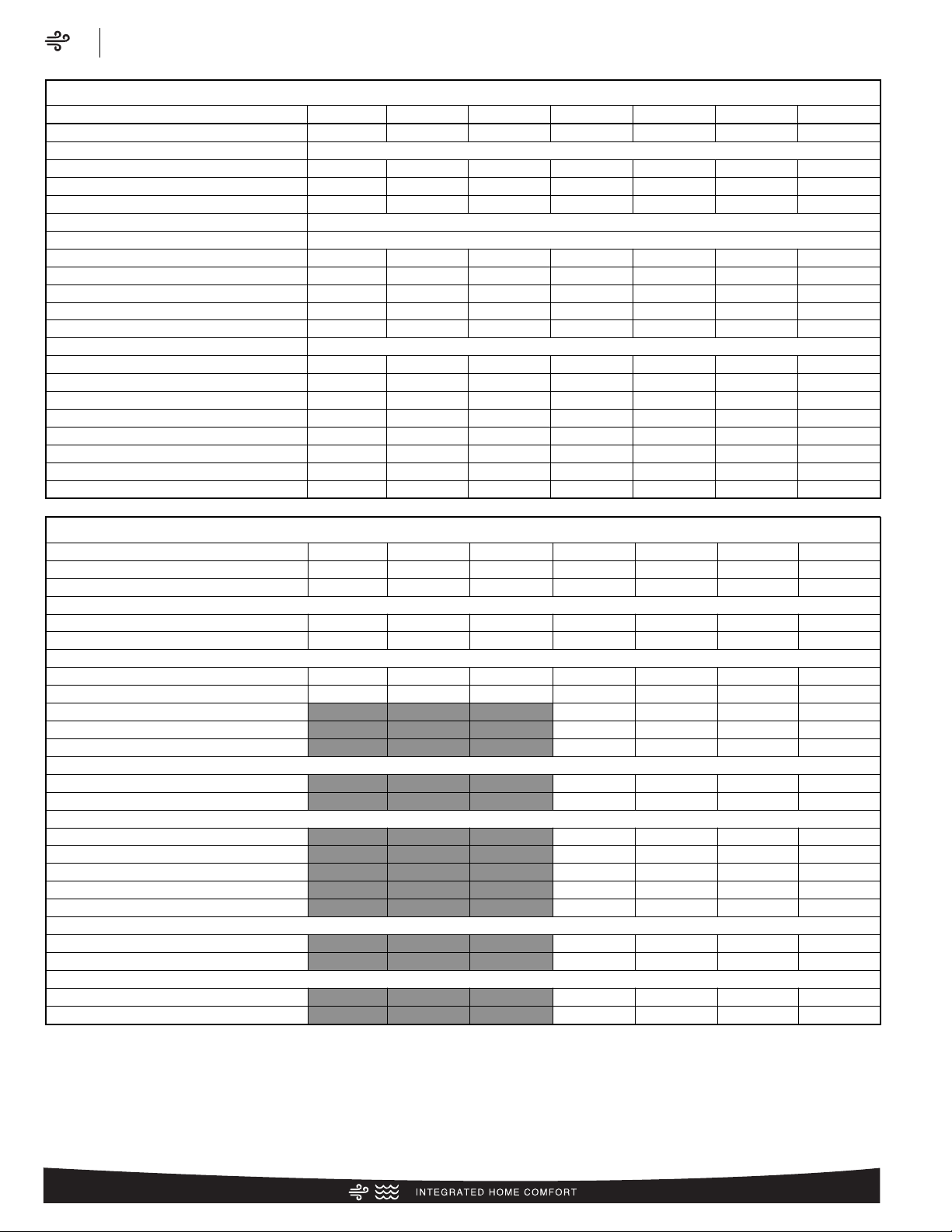
Feature 18 24 30 36 42 48 60
R-410a Refrigerant √ √ √ √ √ √ √
Maximum SEER 15.0 15.0 15.0 15.0 15.0 15.0 15.0
Maximum EER 12.5 12.5 12.5 12.5 12.5 12.5 12.5
Scroll Compressor √ √ √ √ √ √ √
Field Installed Filter Drier √ √ √ √ √ √ √
Front Seating Service Valves √ √ √ √ √ √ √
High Pressure Switch √ √ √ √ √ √ √
Low Pressure Switch √ √ √ √ √ √ √
Internal Pressure Relief Valve √ √ √ √ √ √ √
Internal Thermal Overload √ √ √ √ √ √ √
Long Line capability √ √ √ √ √ √ √
Low Ambient capability with Kit √ √ √ √ √ √ √
3-4-5 Service Valve Access √ √ √ √ √ √ √
Composite Basepan √ √ √ √ √ √ √
2 Screw Control Box Access √ √ √ √ √ √ √
15" Access to Internal Components √ √ √ √ √ √ √
Quick release louver panel design √ √ √ √ √ √ √
No fasteners to remove along bottom √ √ √ √ √ √ √
Optimized Venturi Airflow √ √ √ √ √ √ √
Single row condenser coil √ √ √ √ √ √ √
Powder coated paint √ √ √ √ √ √ √
Rust resistant screws √ √ √ √ √ √ √
QR code √ √ √ √ √ √ √
External gauge ports √ √ √ √ √ √ √
Service trays √ √ √ √ √ √ √
√ = Standard
Standard Feature Table
Available SKU
Available Models Description
RP1518AJ1NA
Classic
®
1 1/2 ton 15 SEER Single-Stage Heat Pump-208/230/1/60
RP1524AJ1NA
Classic
®
2 ton 15 SEER Single-Stage Heat Pump-208/230/1/60
RP1530AJ1NA
Classic
®
2 1/2 ton 15 SEER Single-Stage Heat Pump-208/230/1/60
RP1536AJ1NA
Classic
®
3 ton 15 SEER Single-Stage Heat Pump-208/230/1/60
RP1542AJ1NA
Classic
®
3 1/2 ton 15 SEER Single-Stage Heat Pump-208/230/1/60
RP1548AJ1NA
Classic
®
4 ton 15 SEER Single-Stage Heat Pump-208/230/1/60
RP1560AJ1NA
Classic
®
5 ton 15 SEER Single-Stage Heat Pump-208/230/1/60
RP1536AC1NA
Classic
®
3 ton 15 SEER Single-Stage Heat Pump-208/230/3/60
RP1542AC1NA
Classic
®
3 1/2 ton 15 SEER Single-Stage Heat Pump-208/230/3/60
RP1548AC1NA
Classic
®
4 ton 15 SEER Single-Stage Heat Pump-208/230/3/60
RP1560AC1NA
Classic
®
5 ton 15 SEER Single-Stage Heat Pump-208/230/3/60
RP1536AD1NA
Classic
®
3 ton 15 SEER Single-Stage Heat Pump-460/3/60
RP1542AD1NA
Classic
®
3 1/2 ton 15 SEER Single-Stage Heat Pump-460/3/60
RP1548AD1NA
Classic
®
4 ton 15 SEER Single-Stage Heat Pump-460/3/60
RP1560AD1NA
Classic
®
5 ton 15 SEER Single-Stage Heat Pump-460/3/60
Page 4
Air
Features & Benefits
RP15 Series
4
The RP15 is our 15 SEER heat pump and is part of the Rheem
heat pump product line that extends from 14 to 20 SEER. This
highly featured and reliable heat pump is designed for years of
reliable, efficient operation when matched with Rheem indoor
aluminum evaporator coils and furnaces or air handler units with
aluminum evaporators.
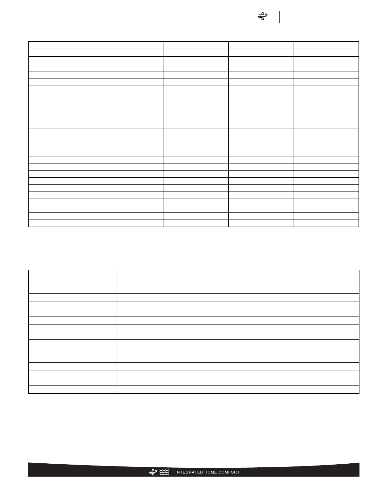
Our unique composite base ( ) reduces sound emission, eliminates rattles, significantly reduces fasteners, eliminates corrosion
and has integrated brass compressor attachment inserts
()
.
Furthermore it has incorporated into the design, water management features, means for hand placement
()
for unit maneu-
vering, screw trays ( ) and inserts for lifting unit off pad. ( )
Service Valves ( ) are rigidly mounted in the composite base
with 3" between suction and discharge valves, 4" clearance
below service valves and a minimum of 5" above the service
valves, creating industry leading installation ease. The minimum
27-square inches around the service valves allows ample room
to remove service valve schrader prior to brazing, plenty of
clearance for easy brazing of the suction and discharge lines to
service valve outlets, easy access and hookup of low loss refrigerant gauges ( ), and access to the service valve caps for
opening. For applications with long-line lengths up to 250 feet
total equivalent length, up to 200 feet heat pump above evaporator, or up to 80 feet evaporator above heat pump, the long-line
instructions in the installation manual should be followed.
Controls are accessed from the corner of the unit by removing
only two fasteners from the control access cover, revealing the
industry’s largest 15" wide and 14" tall control area
()
. With all
this room in the control area the high voltage electrical whip ( )
can easily be inserted through the right size opening in the bottom of the control area. Routing it leads directly to contractor
lugs for connection. The low voltage control wires
()
are easily
connected to units low voltage wiring. If contactor, defrost control or capacitor ( ) needs to be replaced there is more than
adequate space to make the repair. Furthermore, the service
window ( ) can be removed to access the TXV and reversing
valve by removing two screws or the entire corner can be removed
providing ultimate access to the TXV or reversing valve.
()
If in the rare event, greater access is needed to internal components, such as the compressor, the entire corner of the unit can
be removed along with the top cover assembly to have unprecedented access to interior of the unit
()
. Extra wire length is
incorporated into each outdoor fan and compressor so top cover
and control panel can be positioned next to unit. With minimal
effort the plug can be removed from the compressor and the
outdoor fan wires can be removed from the capacitor to allow
even more uncluttered access to the interior of the unit
()
.
Outdoor coils heights range from as short as 25" to 45", aiding
access to the compressor. Disassembly to this degree and complete reassembly only takes a first time service technician less
than 10 minutes.
()
All units utilize strong formed louver panels which provide industry leading coil protection. Louver removal for coil cleaning is
accomplished by removing one screw and lifting the panel out
of the composite base pan
().
All RP15 units utilize single row
coils ( ) making cleaning easy and complete, restoring the
performance of the heat pump back to out of the box performance levels year after year.
The outdoor fan motor has sleeve bearings and is inherently
protected. The motor is totally enclosed for maximum protection
from weather, dust and corrosion. Access to the outdoor fan is
made by removing four fasteners from the fan grille. The outdoor
fan can be removed from the fan grille by removing 4 fasteners
in the rare case outdoor fan motor fails.
Each cabinet has optimized composite ( ) fan orifice assuring
efficient and quiet airflow.
1
2
3
4
7
8
9
10
12
13
14
15
5
6
11
18
17
16
19
Introduction to RP15 Heat Pump
1
4
6
4
3 5
2
8
11
9
10
13
12
16
14
18
15
19
7
17
Page 5
Air
Features & Benefits
RP15 Series
5
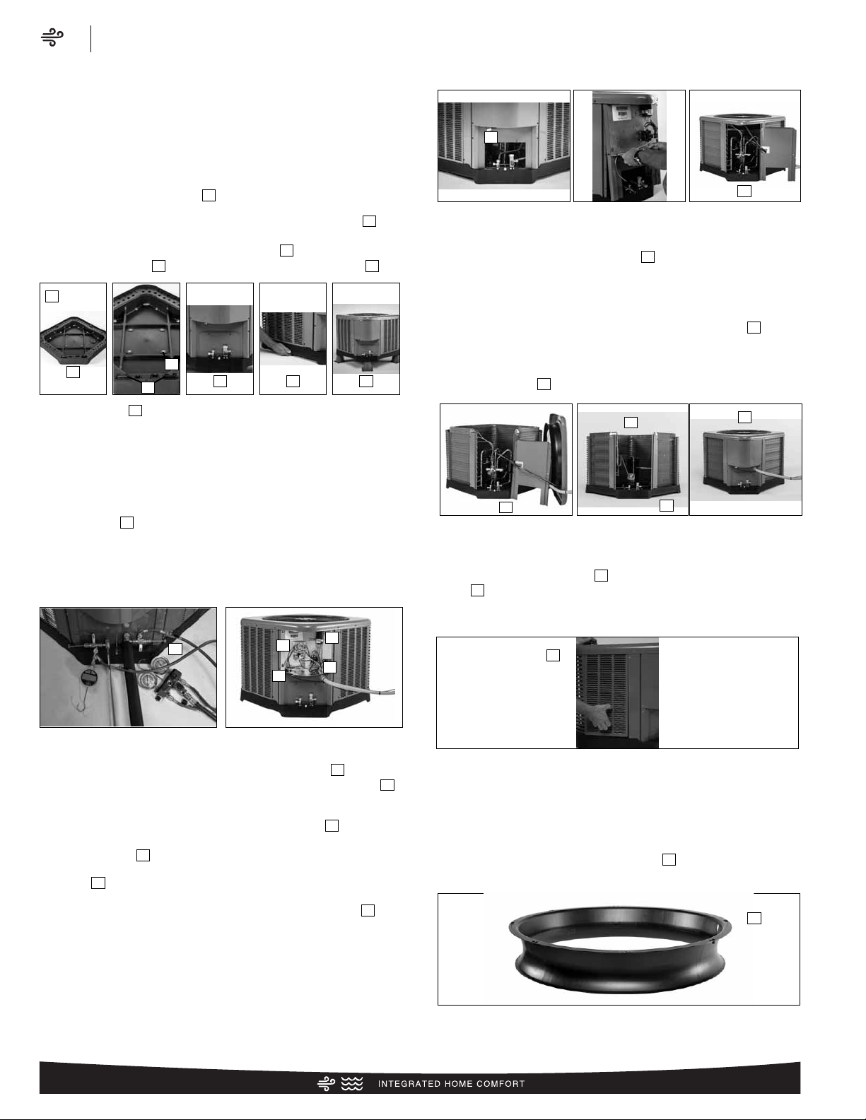
The entire cabinet has powder post paint ( ) achieving 1000
hour salt spray rating, allowing the cabinet to retain its aesthetics
throughout its life.
Scroll compressors with standard internal pressure relief and
internal thermal overload are used on all capacities assuring
longevity of high efficient and quiet operation for the life of the
product. All RP15 Heat Pumps come standard with high and low
pressure switches.
Each unit is shipped with filter drier for field installation and will
trap any moisture or dirt that could contaminate the refrigerant
system.
All cabinets have industry leading structural strength due to the
composite base pan
()
, interlocking corner post
()
, formed
curved louver panels
()
and drawn top cover
()
making it
the most durable cabinet on the market today.
Each RP15 capacity has undergone rigorous psychrometric
testing to assure performance ratings of capacity,
SEER, EER and HSPF per AHRI Standard 210/240
rating conditions. Also each unit bears the UL mark
and each unit is certified to UL 1995 safety standards.
Each unit has undergone specific strain and modal testing to
assure tubing
()
is outside the units natural frequency and that
the suction and discharge lines connected to the compressor
withstand any starting, steady state operation or shut down
forces imposed by the compressor.
All units have been sound tested in sound chamber to AHRI 270
rating conditions, and A-weighted Sound Power Level tables
produced, assuring units have acceptable noise qualities (see
page 9). Each unit has been ran in cooling operation at 95°F and
47°F and sound ratings for the RP15 range from as low as 73
dBA to 79 dBA.
All units have been ship tested to assure units meet stringent
“over the road” shipping conditions.
As manufactured all units in the RP15 family have cooling capability to 55 °F. Addition of low ambient control will allow the unit
to operate down to 0°F.
Factory testing is performed on each unit. All component parts
meet well defined specification and continually go through
receiving inspections. Each component installed on a unit is
scanned, assuring correct component utilization for a given unit
capacity and voltage. All condenser coils are leak tested with
pressurization test to 550#’s and once installed and assembled,
each units’ complete refrigerant system is helium leak tested. All
units are fully charged from the factory for up to 15 feet of piping. All units are factory run tested. The RP15 has a 10-year
conditional compressor and parts warranty (registration required).
Optional Accessories (Refer to accessory chart for model #)
Compressor Crankcase Heater
• Protects against refrigerant migration that can occur during
low ambient operation
Compressor Sound Cover
• Reinforced vinyl compressor cover containing a 1½ inch thick
batt of fiberglass insulation
• Open edges are sealed with a one-inch wide hook and loop
fastening tape
Compressor hard Start Kit
• Single-phase units are equipped with a PSC compressor
motor. This type of motor normally does not need a potential
relay and start capacitor
• In conditions such as low voltage, this kit may be required to
increase the compressor starting torque
Low Ambient Kit
• Heat Pump operate satisfactorily in the cooling mode down to
55°F outdoor air temperature without any additional controls
• Kit can be added in the field enabling unit to operate properly
down to 0° in the cooling mode
• Crankcase heater and freezestat should be installed on compressors equipped with a low ambient kit
3"/6"/12"
• Gray high density polyethylene feet are available to raise unit
off of mounting surface away from moisture
21 22
23 24
25
20
20
24
23
22
21
25
Page 6

Air
Model Number Identification
RP15 Series
6
R
P 15 24 A
J
1 N A *
Brand Product
Category
SEER Capacity
BTU/HR
Major Series* Voltage Type Controls Minor
Series**
Option
Code
Rheem
P - Heat Pump 13 - 13 SEER
14 - 14 SEER
15 - 15 SEER
17 - 17 SEER
20 - 20 SEER
18 - 18,000 [5.28 kW]
24 - 24,000 [7.03 kW]
30 - 30,000 [8.79 kW]
36 - 36,000 [10.55 kW]
42 - 42,000 [12.31 kW]
48 - 48,000 [14.07 kW]
60 - 60,000 [17.58 kW]
A - 1st Design
J - 1ph, 208-230/60
C - 3ph, 208-230/60
D - 3ph, 460/60
1 - Single-stage
V - Inverter
P - Piston
C - Communicating
N - Non-communicating
A - 1st Design N/A
R
C F 24 17
S
T A M C A *
Brand Product
Category
Type Capacity
BTU/HR
Width Efficiency Metering
Device
Major Series* Orientation Casing Minor Series** Option
Code
Rheem
C - Evap Coil F - Furn Coil
H - Air-Handler Coil
24 - 24,000 [7.03 kW]
36 - 36,000 [10.55 kW]
48 - 48,000 [14.07 kW]
60 - 60,000 [17.58 kW]
14 - 14"
17 - 17.5"
21 - 21"
24 - 24.5"
S- Standard Eff.
M- Mid Eff.
H- High Eff.
T-TXV
E-EEV
P-Piston
A -1st Design M - Multi-poise C - Cased
U - Uncased
A - 1st Design N/A
Heat Pumps
R
A 14 24 A
J
1 N A *
Brand Product
Category
SEER Capacity
BTU/HR [kW]
Major Series* Voltage Type Controls Minor Series** Option Code
Rheem A - Air Conditioners
13 - 13 SEER
14 - 14 SEER
16 - 16 SEER
17 - 17 SEER
20 - 20 SEER
18 - 18,000 [5.28 kW]
24 - 24,000 [7.03 kW]
30 - 30,000 [8.79 kW]
36 - 36,000 [10.55 kW]
42 - 42,000 [12.31 kW]
48 - 48,000 [14.07 kW]
60 - 60,000 [17.58 kW]
A - 1st Design
J - 1ph, 208-230/60
C - 3ph, 208-230/60
D - 3ph, 460/60
1 - Single-stage
2 - Two-stage
V - Inverter
C - Communicating
N - Non-communicating
A - 1st Design N/A
Furnace Coils (For Reference)
Air Conditioners (For Reference)
[ ] Designates Metric Conversions
Page 7

R
96 V A
70
2 3 17 M S A
Brand Series Motor Major Rev Input
BTU/HR [kW]
Stages Air Flow Cabinet
Width
Configuration Nox Minor Rev
Rheem
90 - 90 AFUE
92 - 92 AFUE
95 - 95 AFUE
96 - 96 AFUE
97 - 97 AFUE
V - Variable
speed
T - Constant
Torque
(X-13)
P - PSC
A - 1st Design
040 - 42,000 [12.31 kW]
060 - 56,000 [16.41 kW]
070 - 70,000 [20.51 kW]
085 - 84,000 [24.62 kW]
100 - 98,000 [28.72 kW]
115 - 112,000 [32.82 kW]
1 - Single-stage
2 - Two-stage
M- Modulating
3 - up to 3 ton
5 - 3 1/2 up to 5 ton
14 - 14"
17 - 17.5"
21 - 21"
24 - 24.5"
M - Multi-poise X - Low Nox
S - Standard
A - 1st Design
R
80 2 V A
075
3 17 M S A
Brand Series Stages Motor Major Rev Input
BTU/HR [kW]
Air Flow Cabinet
Width
Configuration Nox Minor Rev
Rheem
80 - 80+ AFUE 1 - Single-stage
2 - Two-stage
V - Variable speed
T - Constant Torque (X-13)
P - PSC premium
S - PSC standard
A - 1st Design
050 - 50,000 [15 kW]
075 - 75,000 [22 kW]
100 - 100,000 [29 kW]
125 - 125,000 [37 kW]
150 - 150,000 [44 kW]
3 - up to 3 ton
4 - 2 1/2 to 4 ton
5 - 3 1/2 up to 5 ton
14 - 14"
17 - 17.5"
21 - 21"
24 - 24.5"
M - Multi
D - Down
Z - Down &
zero clearance
down flow
X - Low Nox
S - Standard
A - 1st
Design
90%+ AFUE Gas Furnaces (For Reference)
80% AFUE Gas Furnaces (For Reference)
R
H 1 T 36
17
S T A N A A 000 *
Brand Product
Category
Stages of
Airflow
Motor Type Capacity
BTU/HR
Width Coil Size Metering
Device
Major Series* Controls Voltage Minor
Series**
Factory
Heat Cap
Option
Code
Rheem
H - Air Handler 1 - Single-stage
2 - Two-stage
M - Modulating
V - Variable Speed
T - Constant Torque
P - PSC
24 - 24,000 [7.03 kW]
36 - 36,000 [10.55 kW]
48 - 48,000 [14.07 kW]
60 - 60,000 [17.58 kW]
14 - 14"
17 - 17.5"
21 - 21"
24 - 24.5"
S - Standard Efficiency
M -Mid Efficiency
H - High Efficiency
T - TEV
E - EEV
P - Piston
A -1st Design C - Communicating
N - Non-communicating
A - 1ph, 115/60
J - 1ph, 208-240/60
D - 3ph, 480/60
A -1st
Design
00 - no
factory
heat with
option
code
N/A
Air Handlers (For Reference)
Air
Model Number Identification
RP15 Series
7
[ ] Designates Metric Conversions
Page 8
Physical Data
Model No.# RP1518A RP1524A RP1530A RP1536A RP1542A RP1548A RP1560A
Nominal Tonnage 1.5 2.0 2.5 3.0 3.5 4.0 5.0
Valve Connections
Liquid Line O.D. – in. 3/8 3/8 3/8 3/8 3/8 3/8 3/8
Suction Line O.D. – in. 3/4 3/4 3/4 3/4 7/8 7/8 7/8
Refrigerant (R410A) furnished oz.¹ 106 94 128 124 145 194 223
Compressor Type Scroll
Outdoor Coil
Net face area – Outer Coil 9.1 11.1 17.3 19.8 19.8 24.2 28.3
Net face area – Inner Coil — — — — — — —
Tube diameter – in. 3/8 3/8 3/8 3/8 3/8 3/8 3/8
Number of rows 1 1 1 1 1 1 1
Fins per inch 20 20 20 20 20 20 20
Outdoor Fan
Diameter – in. 20 20 24 24 24 26 26
Number of blades 2 3 3 3 3 3 3
Motor hp 1/8 1/8 1/5 1/3 1/5 1/3 1/5
CFM 2200 2480 3850 3120 3815 4380 3655
RPM 1075 1075 825 910 825 870 850
watts 156 132 196 135 202 266 274
Shipping weight – lbs. 130 138 167 179 187 215 243
Operating weight – lbs. 123 131 160 172 180 208 236
Electrical Data
Line Voltage Data (Volts-Phase-Hz)
208/230-1-60 208/230-1-60 208/230-1-60 208/230-1-60 208/230-1-60 208/230-1-60 208/230-1-60
Maximum overcurrent protection (amps)² 20 25 30 35 40 40 50
Minimum circuit ampacity³ 12 17 19 23 24 26 31
Compressor
Rated load amps 9 12.8 14.1 15.4 17.9 18.5 23.7
Locked rotor amps 48 58.3 73 83.9 112 124 152.5
Condenser Fan Motor
Full load amps 0.7 0.7 1 2.8 1 2.8 1
Locked rotor amps 1.2 1.3 1.5 0 1.5 0 2.3
Line Voltage Data (Volts-Phase-Hz) — — — 208/230-3-60 208/230-3-60 208/230-3-60 208/230-3-60
Maximum overcurrent protection (amps)² — — — 25 30 30 35
Minimum circuit ampacity³ — — — 16 18 21 21
Compressor
Rated load amps — — — 10.4 13.5 13.8 15.9
Locked rotor amps — — — 73 88 83.1 110
Condenser Fan Motor
Full load amps — — — 2.8 1 2.8 1
Locked rotor amps — — — 0 1.5 0 2.3
Line Voltage Data (Volts-Phase-Hz) — — — 480-3-60 480-3-60 480-3-60 480-3-60
Maximum overcurrent protection (amps)² — — — TBD TBD TBD TBD
Minimum circuit ampacity³ — — — TBD TBD TBD TBD
Compressor
Rated load amps — — — TBD TBD TBD TBD
Locked rotor amps — — — TBD TBD TBD TBD
Condenser Fan Motor
Full load amps — — — TBD TBD TBD TBD
Locked rotor amps — — — TBD TBD TBD TBD
¹Refrigerant charge sufficient for 15 ft. length of refrigerant lines. For longer line set requirements see the installation instructions for information about set length and additional
refrigerant charge required.
²HACR type circuit breaker of fuse.
³Refer to National Electrical Code manual to determine wire, fuse and disconnect size requirements.
Air
Physical Data/Electrical Data
RP15 Series
8
Page 9
Accessories
Model No. RP1518 RP1524 RP1530 RP1536 RP1542 RP1548 RP1560
Compressor crankcase heater 44-17402-44 44-17402-44 44-17402-44 44-17402-44 44-17402-45 Factory Standard Factory Standard
Low ambient control RXAD-A08 RXAD-A08 RXAD-A08 RXAD-A08 RXAD-A08 RXAD-A08 RXAD-A08
Compressor sound cover 68-23427-26 68-23427-26 68-23427-26 68-23427-26 68-23427-25 68-23427-25 68-23427-25
Compressor hard start kit SK-A1 SK-A1 SK-A1 SK-A1 SK-A1 SK-A1 SK-A1
Low pressure control* Factory Standard Factory Standard Factory Standard Factory Standard Factory Standard Factory Standard Factory Standard
High pressure control* Factory Standard Factory Standard Factory Standard Factory Standard Factory Standard Factory Standard Factory Standard
Liquid Line Solenoid
(24 VAC, 50/60 Hz)
Solenoid Valve 200RD2T3TVLC 200RD2T3TVLC 200RD2T3TVLC 200RD2T3TVLC 200RD2T3TVLC 200RD3T3TVLC 200RD3T3TVLC
Solenoid Coil 61-AMG24V 61-AMG24V 61-AMG24V 61-AMG24V 61-AMG24V 61-AMG24V 61-AMG24V
Bi-flow kit* KS30387 KS30387 KS30387 KS30387 KS30387 KS30387 KS30387
Liquid Line Solenoid
(120/240 VAC, 50/60 Hz)
Solenoid Valve 200RD2T3TVLC 200RD2T3TVLC 200RD2T3TVLC 200RD2T3TVLC 200RD2T3TVLC 200RD3T3TVLC 200RD3T3TVLC
Solenoid Coil 61-AMG120/240V 61-AMG120/240V 61-AMG120/240V 61-AMG120/240V 61-AMG120/240V 61-AMG120/240V 61-AMG120/240V
Bi-flow kit* KS30387 KS30387 KS30387 KS30387 KS30387 KS30387 KS30387
Classic Top Cap w/Label 91-101123-21 91-101123-21 91-101123-21 91-101123-21 91-101123-21 91-101123-21 91-101123-21
*Bi-flow kits are required when installing a liquid line solenoid on a heat pump.
Weighted Sound Power Level (dBA)
Unit Size – Voltage, Series Standard Rating (dBA)
TYPICAL OCTAVE BAND SPECTRUM (dBA without tone adjustment)
125 250 500 1000 2000 4000 8000
RP1518A 75.2 53.8 60.2 64.3 66 62.5 57.6 53.5
RP1524A 76.1 51 60.4 65.8 66.6 63.6 59 53.7
RP1530A 73.3 51.8 56.6 63.4 62.9 60.8 55.9 51.5
RP1536A 79 53.5 60.7 68.4 69.4 66.3 61.3 56.1
RP1542A 74.1 52.9 55.9 64 63.5 61.4 58 52.1
RP1548A 76.5 55.8 59 68.2 66.3 64.3 60.5 55.4
RP1560A 73.9 58.9 55.7 63.4 63.3 61.5 58.6 56.4
NOTE: Tested in accordance with AHRI Standard 270-08 (not listed in AHRI)
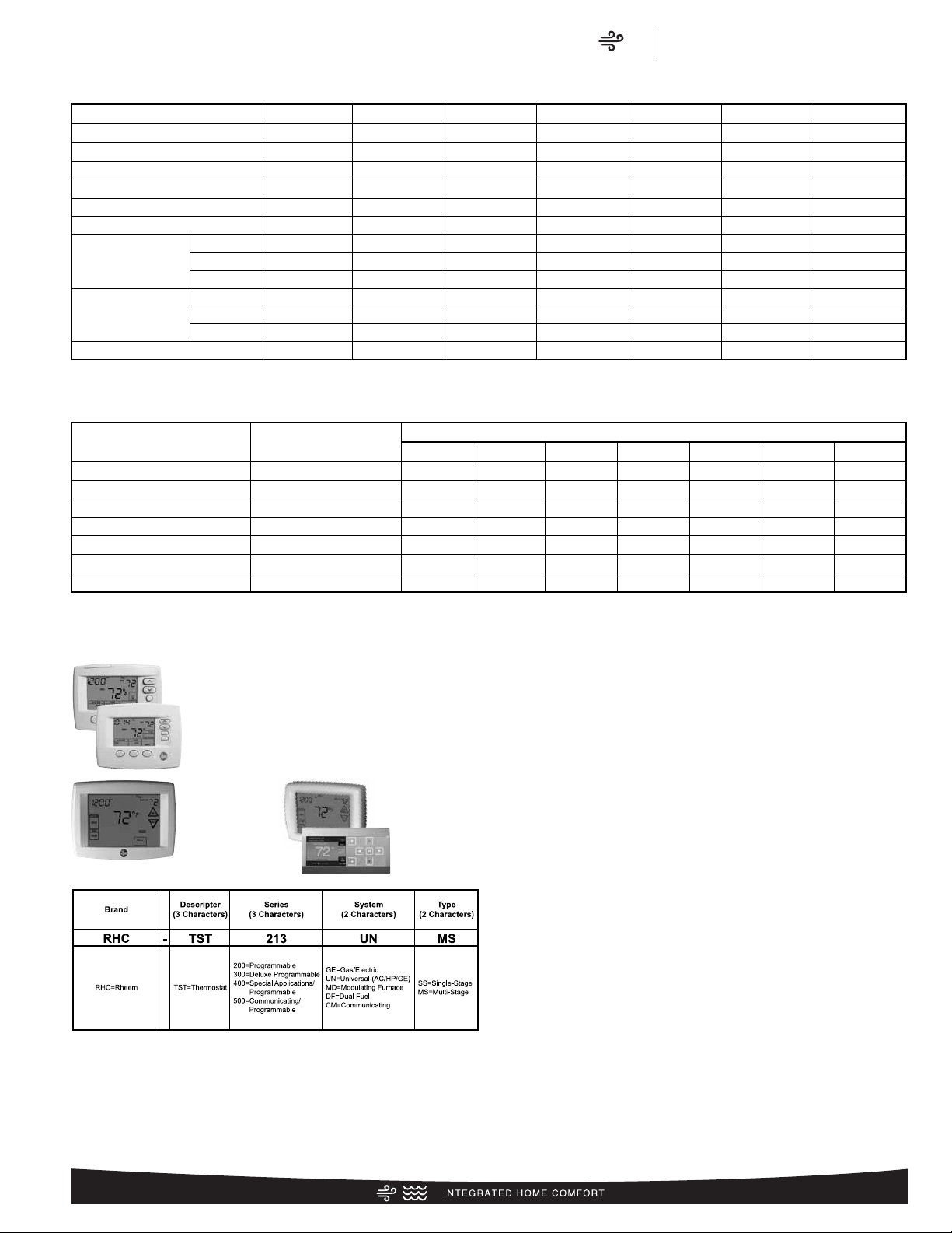
* Photos are representative. Actual models may vary.
For detailed thermostat match-up information,
see specification sheet form number T11-001.
300-Series *
Deluxe
Programmable
400-Series *
Special Applications/
Programmable
500-Series *
Communicating/
Programmable
200-Series *
Programmable
Thermostats
Air
Accessories/Weighted Sound Power/Thermostats
RP15 Series
9
Page 10
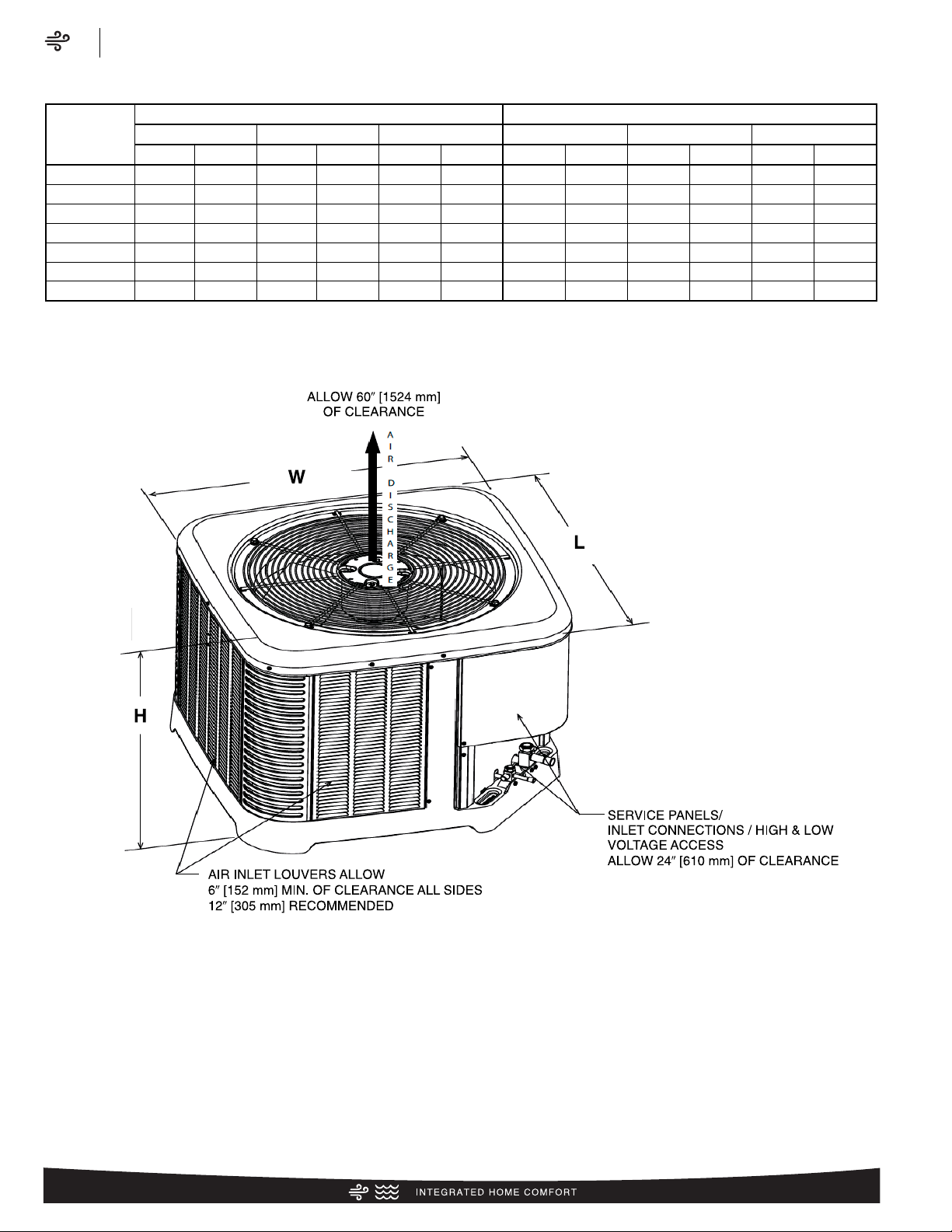
Unit Dimensions
MODEL
NUMBER
OPERATING SHIPPING
H (Height) L (Length) W (Width) H (Height) L (Length) W (Width)
INCHES mm INCHES mm INCHES mm INCHES mm INCHES mm INCHES mm
RP1518 25 635 29.75 755 29.75 755 26.75 679 32.38 822 32.38 822
RP1524 25 635 29.75 755 29.75 755 26.75 679 32.38 822 32.38 822
RP1530 31 787 33.75 857 33.75 857 32.75 831 32.38 822 32.38 822
RP1536 35 889 33.75 857 33.75 857 36.75 933 36.38 924 36.38 924
RP1542 35 889 33.75 857 33.75 857 36.75 933 36.38 924 36.38 924
RP1548 39 990 35.75 908 35.75 908 40.75 1035 38.38 974 38.38 974
RP1560 45 1143 35.75 908 35.75 908 46.75 1187 38.38 974 38.38 974
[ ] Designates Metric Conversions
ST-A1226-02-00
Air
Unit Dimensions
RP15 Series
10
Page 11
6⬙
(152.4)
24⬙
(609.6)
Service
12⬙
(304.8)
6⬙
(152.4)
24⬙
(609.6)
Service
24⬙
(609.6)
24⬙ recommended
9⬙ minimum
12⬙
(304.8)
12⬙
(304.8)
6⬙
(152.4)
24⬙
(609.6)
Service
24⬙
(609.6)
Service
24⬙
(609.6)
Service
18⬙
(457.2)
WALL
WALL
WALL
WALL
NOTE: NUMBERS IN () = mm
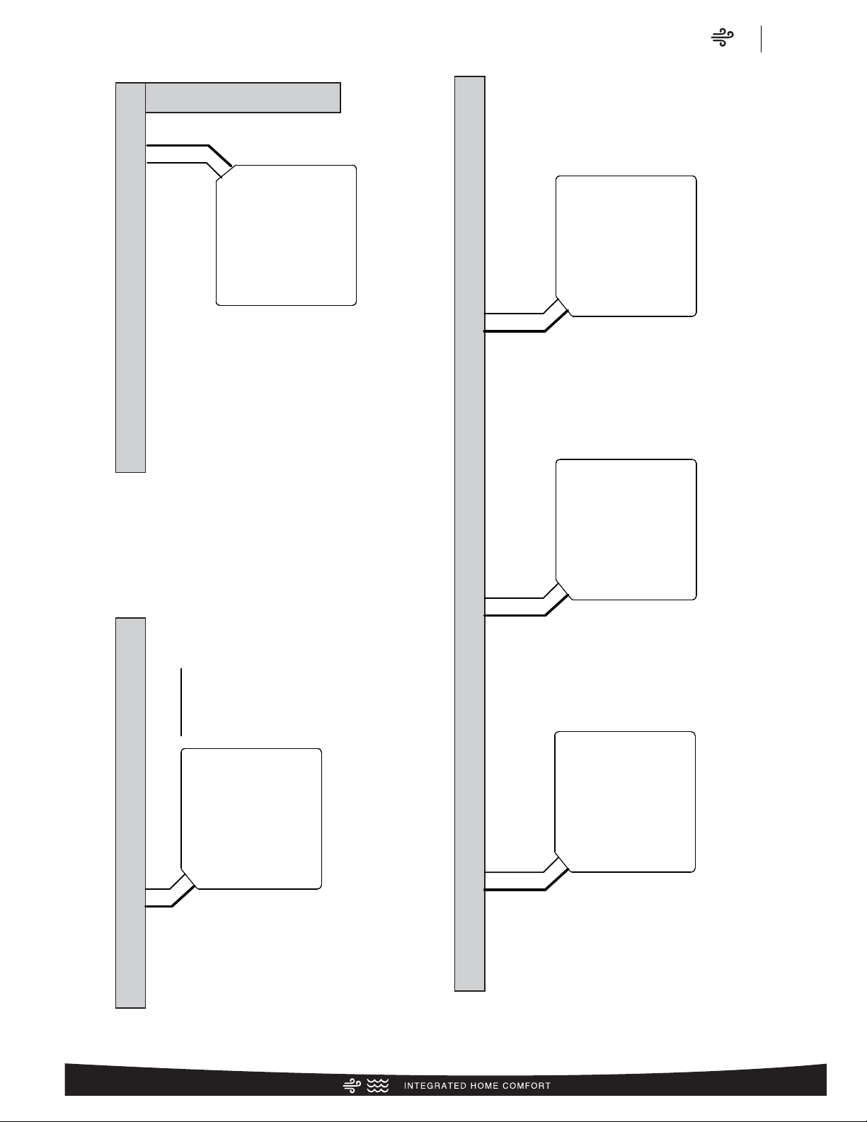
CLEARANCES
IMPORTANT: When installing multiple units in an alcove, roof well or partially enclosed area, ensure there is adequate ventillation to prevent re-circulation of discharge air.
ST-A1225-01-00
24⬙
(609.6)
24⬙ recommended
9⬙ minimum
Air
Clearances
RP15 Series
11
Page 12

Air
Wiring Diagram/Application Guidelines
RP15 Series
12
.
Application Guidelines
1. Intended for outdoor installation with free air inlet and outlet. Outdoor fan external static pressure available is less than 0.01 -in. wc.
2. Minimum outdoor operation air temperature for cooling mode without low-ambient operation accessory is 55°F (12.8°C).
3. Maximum outdoor operating air temperature is 125°F (51.7°C).
4. For reliable operation, unit should be level in all horizontal planes.
5. Use only copper wire for electric connections at unit. Aluminum and clad aluminum are not acceptable for the type of connector
provided.
6. Do not apply capillary tube indoor coils to these units.
7. Factory – supplied filter drier must be installed.
Control Wiring
FIGURE 4
CONTROL WIRING FOR AIR HANDLER
Air Handler
W/BL
W2
G/BK
G
Y
Y
W/BK
W1
BL
B
G/Y
ODD
BR
C
R
R
Y
Heat Pump Thermostat
W2
G
B
Y
TYPICAL THERMOSTAT:
C
E
HEAT PUMP WITH
R
ELECTRIC HEAT
Heat Pump
Outdoor Unit
Y
B
NOTES:
1. Jumper “E” to “W2” to
transfer control of
supplemental heat to
1st stage when the
emergency heat switch
is on.
2. This wire turns on heat
for defrost, omit for most
economical operation.
3. Wire with colored tracing
stripe.
C
R
D
WIRING INFORMATION
Line Voltage
Field Installed
-
Factory Standard
-
NOTE: RED WIRE REQUIRED WITH RANCO DDL DEMAND DEFROST CONTROL
Page 13

Air
Refrigerant Line Size Information
RP15 Series
13
R-410A System
Capacity Model
Liquid Line Size
Connection Size
(Inch I.D.) [mm]
Liquid Line Size
(Inch O.D.) [mm]
Liquid Line Size
Elevation (Above or Below) Indoor Coil
Tot al Equivalent Length - Feet [m]
25 [7.62] 50 [15.24] 75 [22.86] 100 [30.48] 125 [45.72] 150 [45.72] 175 [53.34] 200 [60.96] 225 [68.58] 250 [76.20] 275 [83.82] 300 [91.44]
Maximum Vertical Separation – Feet [m]
18 3/8" [9.53]
1/4 [6.35] 25 [7.62] 50 [15.24] 60 [18.29] 50 [15.24] 35 [10.67] 20 [6.1]
N/R N/R N/R N/R N/R N/R
5/16 [7.94] 25 [7.62] 50 [15.24] 75 [22.86] 90 [27.43] 85 [25.91] 85 [25.91] 80 [24.38] 75 [22.86] 70 [21.34] 70 [21.34] 65 [19.81] 60 [18.29]
3/8 [9.53] 25 [7.62] 50 [15.24] 75 [22.86] 100 [30.48] 100 [30.48] 100 [30.48] 95 [28.96] 95 [28.96] 95 [28.96] 90 [27.43] 90 [27.43] 90 [27.43]
7/16 [11.12] 25 [7.62] 50 [15.24] 75 [22.86] 100 [30.48] 105 [32] 100 [30.48] 100 [30.48] 100 [30.48] 100 [30.48] 100 [30.48] 100 [30.48] 100 [30.48]
1/2 [12.71] 25 [7.62] 50 [15.24] 75 [22.86] 100 [30.48] 105 [32] 105 [32] 105 [32] 105 [32] 105 [32] 105 [32] 100 [30.48] 100 [30.48]
24 3/8" [9.53]
1/4 [6.35] 25 [7.62] 50 [15.24] 30 [9.14]
N/R N/R N/R N/R N/R N/R N/R N/R N/R
5/16 [7.94] 25 [7.62] 50 [15.24] 75 [22.86] 80 [24.38] 70 [21.34] 65 [19.81] 60 [18.29] 50 [15.24] 45 [13.72] 40 [12.19] 35 [10.67] 25 [7.62]
3/8 [9.53] 25 [7.62] 50 [15.24] 75 [22.86] 95 [28.96] 90 [27.43] 90 [27.43] 90 [27.43] 85 [25.91] 85 [25.91] 80 [24.38] 80 [24.38] 75 [22.86]
7/16 [11.12] 25 [7.62] 50 [15.24] 75 [22.86] 100 [30.48] 100 [30.48] 95 [28.96] 95 [28.96] 95 [28.96] 95 [28.96] 95 [28.96] 95 [28.96] 90 [27.43]
1/2 [12.71] 25 [7.62] 50 [15.24] 75 [22.86] 100 [30.48] 100 [30.48] 100 [30.48] 100 [30.48] 100 [30.48] 100 [30.48] 100 [30.48] 95 [28.96] 95 [28.96]
30 3/8" [9.53]
1/4 [6.35] 25 [7.62] 30 [9.14]
N/R N/R N/R N/R N/R N/R N/R N/R N/R N/R
5/16 [7.94] 25 [7.62] 50 [15.24] 70 [21.34] 60 [18.29] 55 [16.76] 45 [13.72] 35 [10.67] 30 [9.14] 20 [6.1] 10 [3.05] N/R N/R
3/8 [9.53] 25 [7.62] 50 [15.24] 75 [22.86] 85 [25.91] 80 [24.38] 80 [24.38] 75 [22.86] 70 [21.34] 70 [21.34] 65 [19.81] 65 [19.81] 60 [18.29]
7/16 [11.12] 25 [7.62] 50 [15.24] 75 [22.86] 90 [27.43] 90 [27.43] 90 [27.43] 85 [25.91] 85 [25.91] 85 [25.91] 85 [25.91] 80 [24.38] 80 [24.38]
1/2 [12.71] 25 [7.62] 50 [15.24] 75 [22.86] 95 [28.96] 95 [28.96] 90 [27.43] 90 [27.43] 90 [27.43] 90 [27.43] 90 [27.43] 90 [27.43] 90 [27.43]
36 3/8" [9.53]
1/4 [6.35] 25 [7.62]
N/R N/R N/R N/R N/R N/R N/R N/R N/R N/R N/R
5/16 [7.94] 25 [7.62] 50 [15.24] 65 [19.81] 50 [15.24] 40 [12.19] 25 [7.62] 15 [4.57]
N/R N/R N/R N/R N/R
3/8 [9.53] 25 [7.62] 50 [15.24] 75 [22.86] 85 [25.91] 80 [24.38] 75 [22.86] 70 [21.34] 65 [19.81] 65 [19.81] 60 [18.29] 55 [16.76] 50 [15.24]
7/16 [11.12] 25 [7.62] 50 [15.24] 75 [22.86] 95 [28.96] 95 [28.96] 90 [27.43] 90 [27.43] 85 [25.91] 85 [25.91] 85 [25.91] 80 [24.38] 80 [24.38]
1/2 [12.71] 25 [7.62] 50 [15.24] 75 [22.86] 100 [30.48] 95 [28.96] 95 [28.96] 95 [28.96] 95 [28.96] 95 [28.96] 95 [28.96] 90 [27.43] 90 [27.43]
42 3/8" [9.53]
1/4 [6.35] 25 [7.62]
N/R N/R N/R N/R N/R N/R N/R N/R N/R N/R N/R
5/16 [7.94] 25 [7.62] 50 [15.24] 45 [13.72] 30 [9.14] 10 [3.05]
N/R N/R N/R N/R N/R N/R N/R
3/8 [9.53] 25 [7.62] 50 [15.24] 75 [22.86] 75 [22.86] 65 [19.81] 60 [18.29] 55 [16.76] 50 [15.24] 45 [13.72] 40 [12.19] 30 [9.14] 25 [7.62]
7/16 [11.12] 25 [7.62] 50 [15.24] 75 [22.86] 85 [25.91] 85 [25.91] 80 [24.38] 80 [24.38] 75 [22.86] 75 [22.86] 70 [21.34] 70 [21.34] 65 [19.81]
1/2 [12.71] 25 [7.62] 50 [15.24] 75 [22.86] 90 [27.43] 90 [27.43] 90 [27.43] 90 [27.43] 85 [25.91] 85 [25.91] 85 [25.91] 85 [25.91] 80 [24.38]
48 3/8" [9.53]
1/4 [6.35] 10 [3.05]
N/R N/R N/R N/R N/R N/R N/R N/R N/R N/R N/R
5/16 [7.94] 25 [7.62] 50 [15.24] 30 [9.14] 10 [3.05]
N/R N/R N/R N/R N/R N/R N/R N/R
3/8 [9.53] 25 [7.62] 50 [15.24] 70 [21.34] 65 [19.81] 55 [16.76] 50 [15.24] 40 [12.19] 35 [10.67] 30 [9.14] 20 [6.1] 15 [4.57] 10 [3.05]
7/16 [11.12] 25 [7.62] 50 [15.24] 75 [22.86] 80 [24.38] 75 [22.86] 75 [22.86] 70 [21.34] 70 [21.34] 65 [19.81] 60 [18.29] 60 [18.29] 55 [16.76]
1/2 [12.71] 25 [7.62] 50 [15.24] 75 [22.86] 85 [25.91] 85 [25.91] 80 [24.38] 80 [24.38] 80 [24.38] 80 [24.38] 75 [22.86] 75 [22.86] 75 [22.86]
60 3/8" [9.53]
1/4 [6.35]
N/R N/R N/R N/R N/R N/R N/R N/R N/R N/R N/R N/R
5/16 [7.94] 25 [7.62] 10 [3.05]
N/R N/R N/R N/R N/R N/R N/R N/R N/R N/R
3/8 [9.53] 25 [7.62] 50 [15.24] 40 [12.19] 30 [9.14] 20 [6.1] 10 [3.05]
N/R N/R N/R N/R N/R N/R
7/16 [11.12] 25 [7.62] 50 [15.24] 55 [16.76] 50 [15.24] 50 [15.24] 45 [13.72] 40 [12.19] 35 [10.67] 30 [9.14] 25 [7.62] 25 [7.62] 20 [6.1]
1/2 [12.71] 25 [7.62] 50 [15.24] 60 [18.29] 60 [18.29] 60 [18.29] 55 [16.76] 55 [16.76] 50 [15.24] 50 [15.24] 50 [15.24] 45 [13.72] 45 [13.72]
Heat Pump Refrigerant Line Size Information
NOTES: [ ] Designates Metric Conversions
N/R = Application not recommended.
Grey =This application is acceptable, but the long line guidelines must be followed. Reference Long Line Set section in the I&O
Page 14

Air
Refrigerant Line Size Information
RP15 Series
14
R-410A System
Capacity Model
Vapor Line
Connection Size
(Inch I.D.) [mm]
Vapor Line Size
(Inch O.D.) [mm]
Vapor Line Selection Chart
Capacity Multiplier Table
Tot al Equivalent Length - Feet [m]
25 [7.62] 50 [15.24] 75 [22.86] 100 [30.48] 125 [45.72] 150 [45.72] 175 [53.34] 200 [60.96] 225 [68.58] 250 [76.20] 275 [83.82] 300 [91.44]
18 3/4" [19.06]
5/8 [15.88]
1.00 1.00 1.00 0.99 0.99 0.98 0.98 0.98 0.97 0.97 0.97 0.97
3/4 [19.05]
1.00 1.00 1.00 1.00 1.00 1.00 1.00 1.00 1.00 1.00 1.00 1.00
7/8 [22.23]
N/R N/R N/R N/R N/R N/R N/R N/R N/R N/R N/R N/R
1 [25.4]
N/R N/R N/R N/R N/R N/R N/R N/R N/R N/R N/R N/R
1-1/8 [28.58]
N/R N/R N/R N/R N/R N/R N/R N/R N/R N/R N/R N/R
24 3/4" [19.06]
5/8 [15.88]
1.00 0.99 0.98 0.98 0.97 0.97 0.96 0.96 0.95 0.95 0.94 0.93
3/4 [19.05]
1.00 1.00 1.00 0.99 1.00 0.99 0.99 1.00 0.99 0.99 0.99 0.99
7/8 [22.23]
1.00 1.00 1.00 1.00 0.99 1.00 1.00 1.00 1.00 1.00 1.01 1.01
1 [25.4]
N/R N/R N/R N/R N/R N/R N/R N/R N/R N/R N/R N/R
1-1/8 [28.58]
N/R N/R N/R N/R N/R N/R N/R N/R N/R N/R N/R N/R
30 3/4" [19.06]
5/8 [15.88]
0.99 0.98 0.97 0.95 0.94 0.94 0.93 0.92 0.91 0.91 0.9 0.88
3/4 [19.05]
1.00 1.00 0.99 0.98 0.98 0.98 0.97 0.97 0.97 0.96 0.96 0.95
7/8 [22.23]
1.00 1.00 1.00 1.00 1.00 0.99 0.99 0.98 0.98 0.98 0.98 0.98
1 [25.4]
1.00 1.00 1.00 1.00 1.00 1.00 1.00 1.00 1.00 1.00 0.99 0.99
1-1/8 [28.58]
N/R N/R N/R N/R N/R N/R N/R N/R N/R N/R N/R N/R
36 3/4" [19.06]
5/8 [15.88]
1.00 0.97 0.97 0.95 0.94 0.93 0.91 0.92 0.91 0.88 0.87 0.86
3/4 [19.05]
1.00 1.00 0.99 0.98 0.99 0.99 0.98 0.97 0.97 0.96 0.96 0.95
7/8 [22.23]
1.01 1.01 1.01 1.00 1.00 1.00 1.00 1.00 1.00 0.99 0.98 0.98
1 [25.4]
1.01 1.01 1.01 1.01 1.01 1.01 1.01 1.00 1.00 1.00 1.00 1.01
1-1/8 [28.58]
N/R N/R N/R N/R N/R N/R N/R N/R N/R N/R N/R N/R
42 3/4" [19.06]
5/8 [15.88]
1.00 0.98 0.96 0.95 0.94 0.92 0.91 0.89 0.88 0.87 0.86 0.85
3/4 [19.05]
1.01 1.01 1.00 0.99 0.99 0.98 0.97 0.97 0.96 0.95 0.95 0.94
7/8 [22.23]
1.00 1.01 1.01 1.01 1.01 1.01 1.01 1.00 0.99 1.00 1.00 0.99
1 [25.4]
1.03 1.02 1.02 1.02 1.02 1.01 1.01 1.01 1.01 1.01 1.01 1.01
1-1/8 [28.58]
1.03 1.03 1.02 1.02 1.02 1.02 1.02 1.02 1.02 1.02 1.01 1.01
48 3/4" [19.06]
5/8 [15.88]
0.99 0.96 0.94 0.92 0.91 0.89 0.87 0.86 0.84 0.83 0.82 0.8
3/4 [19.05]
1.01 1.00 0.99 0.97 0.97 0.96 0.95 0.94 0.94 0.93 0.92 0.92
7/8 [22.23]
1.00 1.01 1.01 1.00 1.00 0.99 0.99 0.99 0.98 0.98 0.97 0.97
1 [25.4]
N/R N/R N/R N/R N/R N/R N/R N/R N/R N/R N/R N/R
1-1/8 [28.58]
N/R N/R N/R N/R N/R N/R N/R N/R N/R N/R N/R N/R
60 3/4" [19.06]
5/8 [15.88]
0.79 0.99 0.95 0.93 0.91 0.89
N/R N/R N/R N/R N/R N/R
3/4 [19.05]
0.9 1.01 1.00 0.99 0.97 0.96
N/R N/R N/R N/R N/R N/R
7/8 [22.23]
1.00 1.01 1.01 1.01 1.00 1.00
N/R N/R N/R N/R N/R N/R
1 [25.4]
1.00 1.02 1.01 1.01 1.01 1.01
N/R N/R N/R N/R N/R N/R
1-1/8 [28.58]
N/R N/R N/R N/R N/R N/R N/R N/R N/R N/R N/R N/R
Heat Pump Refrigerant Line Size Information (con’t.)
NOTES: [ ] Designates Metric Conversions
N/R = Application not recommended.
All calculations assume a 3/8" liquid line
Page 15

Air
Performance Data
RP15 Series
15
High Sales Volume Tested Combination (HSVTC)
Outdoor
Unit
Air Handler
Total Capacity
BTU/H [kW]
Net Sensible
BTU/H [kW]
Net Latent
BTU/H [kW]
SEER EER
Indoor CFM
[L/s]
47 Degree Heating
Capacity BTU/H
[kW]
47 Degree
COP
17 Degree Heating
Capacity BTU/H
[kW]
47 Degree
COP
Region
IV HSPF
AHRI#
RP1518AJ1 RH1T2417STAN 18800 [5.5] 13700 [4.0] 5100 [1.5] 15 12.5 575 [271.4] 17000 [5.0] 3.6 10200 [3.0] 2.4 8.5 7508987
RP1524AJ1 RH1T2417STAN 25400 [7.4] 18600 [5.5] 6800 [2.0] 15 12.5 800 [377.6] 22200 [6.5] 3.6 13600 [4.0] 2.4 8.5 7509020
RP1530AJ1 RH1T3617STAN 30200 [8.9] 22700 [6.7] 7500 [2.2] 15.5 13 1050 [495.5] 28200 [8.3] 3.5 16600 [4.9] 2.2 8.2 7509100
RP1536AC1 RH1T3617STAN 35600 [10.4] 26400 [7.7] 9200 [2.7] 15 12.5 1175 [554.5] 33800 [9.9] 3.66 22200 [6.5] 2.66 8.5 7512069
RP1536AJ1 RH1T3617STAN 35600 [10.4] 26400 [7.7] 9200 [2.7] 15 12.5 1175 [554.5] 33800 [9.9] 3.66 22200 [6.5] 2.66 8.5 7512115
RP1542AC1 RH1T4821STAN 42500 [12.5] 30500 [8.9] 12000 [3.5] 15 12.5 1350 [637.1] 40000 [11.7] 3.76 25600 [7.5] 2.6 8.5 7512302
RP1542AJ1 RH1T4821STAN 42500 [12.5] 30500 [8.9] 12000 [3.5] 15 12.5 1350 [637.1] 40000 [11.7] 3.76 25600 [7.5] 2.6 8.5 7512350
RP1548AC1 RH1T4821STAN 47000 [13.8] 34100 [10.0] 12900 [3.8] 15 12.5 1500 [707.9] 44500 [13.0] 3.66 28800 [8.4] 2.6 8.5 7512150
RP1548AJ1 RH1T4821STAN 47000 [13.8] 34100 [10.0] 12900 [3.8] 15 12.5 1500 [707.9] 44500 [13.0] 3.66 28800 [8.4] 2.6 8.5 7512187
RP1560AC1 RH1T6024STAN 58000 [17.0] 42400 [12.4] 15600 [4.6] 15 12.5 1775 [837.7] 56000 [16.4] 3.76 35600 [10.4] 2.66 8.5 7512221
RP1560AJ1 RH1T6024STAN 58000 [17.0] 42400 [12.4] 15600 [4.6] 15 12.5 1775 [837.7] 56000 [16.4] 3.76 35600 [10.4] 2.66 8.5 7512254
Performance Data @ AHRI Standard Conditions – Heat Pump
Coil Only Ratings
Outdoor
Unit
Indoor Coil
Total Capacity
BTU/H [kW]
Net Sensible
BTU/H [kW]
Net Latent
BTU/H [kW]
SEER EER
Indoor CFM
[L/s]
47 Degree Heating
Capacity BTU/H
[kW]
47 Degree
COP
17 Degree Heating
Capacity BTU/H
[kW]
47 Degree
COP
Region
IV HSPF
AHRI#
RP1536AC1
RCF3617STAM+RXMD-C04 34400 [10.1] 23800 [7.0] 10600 [3.1] 14 11.5 1075 [507.3] 33000 [9.7] 3.34 22000 [6.4] 2.46 8.5 7512039
RCF3621STAM+RXMD-C04 34800 [10.2] 24600 [7.2] 10200 [3.0] 14 11.5 1150 [542.7] 31800 [9.3] 3.2 21000 [6.2] 2.34 8.2 7512066
RP1536AJ1
RCF3617STAM+RXMD-C04 34400 [10.1] 23800 [7.0] 10600 [3.1] 14 11.5 1075 [507.3] 33000 [9.7] 3.34 22000 [6.4] 2.46 8.5 7512085
RCF3621STAM+RXMD-C04 34800 [10.2] 24600 [7.2] 10200 [3.0] 14 11.5 1150 [542.7] 31800 [9.3] 3.2 21000 [6.2] 2.34 8.2 7512112
RP1542AC1
RCF4821STAM+RXMD-C04 41500 [12.2] 28600 [8.4] 12900 [3.8] 14 11.5 1350 [637.1] 40000 [11.7] 3.5 25800 [7.6] 2.46 8.5 7512276
RCF4824STAM+RXMD-C04 41500 [12.2] 28600 [8.4] 12900 [3.8] 14 11.5 1350 [637.1] 39500 [11.6] 3.46 25600 [7.5] 2.46 8.5 7512301
RP1542AJ1
RCF4821STAM+RXMD-C04 41500 [12.2] 28600 [8.4] 12900 [3.8] 14 11.5 1350 [637.1] 40000 [11.7] 3.5 25800 [7.6] 2.46 8.5 7512324
RCF4824STAM+RXMD-C04 41500 [12.2] 28600 [8.4] 12900 [3.8] 14 11.5 1350 [637.1] 39500 [11.6] 3.46 25600 [7.5] 2.46 8.5 7512349
RP1548AC1
RCF4821STAM+RXMD-C04 45500 [13.3] 30600 [9.0] 14900 [4.4] 14.5 12 1375 [648.9] 43000 [12.6] 3.3 28000 [8.2] 2.34 8.5 7512130
RCF4824STAM+RXMD-C04 45500 [13.3] 30600 [9.0] 14900 [4.4] 14.5 12 1375 [648.9] 42500 [12.5] 3.3 27800 [8.1] 2.34 8.5 7512148
RP1548AJ1
RCF4821STAM+RXMD-C04 45500 [13.3] 30600 [9.0] 14900 [4.4] 14.5 12 1375 [648.9] 43000 [12.6] 3.3 28000 [8.2] 2.34 8.5 7512167
RCF4824STAM+RXMD-C04 45500 [13.3] 30600 [9.0] 14900 [4.4] 14.5 12 1375 [648.9] 42500 [12.5] 3.3 27800 [8.1] 2.34 8.5 7512185
RP1560AC1
RCF6024HTAM+RXMD-C04 56500 [16.6] 37800 [11.1] 18700 [5.5] 14 11.5 1600 [755.1] 56000 [16.4] 3.6 35600 [10.4] 2.54 8.5 7512204
RCF6024STAM+RXMD-C04 56500 [16.6] 37800 [11.1] 18700 [5.5] 14 11.5 1600 [755.1] 56000 [16.4] 3.6 35600 [10.4] 2.54 8.5 7512220
RP1560AJ1
RCF6024HTAM+RXMD-C04 56500 [16.6] 37800 [11.1] 18700 [5.5] 14 11.5 1600 [755.1] 56000 [16.4] 3.6 35600 [10.4] 2.54 8.5 7512237
RCF6024STAM+RXMD-C04 56500 [16.6] 37800 [11.1] 18700 [5.5] 14 11.5 1600 [755.1] 56000 [16.4] 3.6 35600 [10.4] 2.54 8.5 7512253
[ ] Designates Metric Conversions
Page 16

Air
Performance Data
RP15 Series
16
R801T: Classic Plus Single-Stage X-13 80% Furnace Ratings
Outdoor
Unit
Furnace Indoor Coil
Total Capacity
BTU/H [kW]
Net Sensible
BTU/H [kW]
Net Latent
BTU/H [kW]
SEER EER
Indoor CFM
[L/s]
47 Degree Heating
Capacity BTU/H
[kW]
47 Degree
COP
17 Degree Heating
Capacity BTU/H
[kW]
47 Degree
COP
Region
IV HSPF
AHRI#
RP1518AJ1 R801TA050314MSA RCF2417STAM 19000 [5.6] 13900 [4.1] 5100 [1.5] 15 12.5 625 [295.0] 17000 [5.0] 3.6 10300 [3.0] 2.4 8.5 7508962
RP1518AJ1 R801TA075317ZSA RCF2417STAM 19100 [5.6] 14100 [4.1] 5000 [1.5] 15 12.5 650 [306.8] 17100 [5.0] 3.54 10400 [3.0] 2.4 8.2 7508963
RP1524AJ1 R801TA050314MSA RCF2417STAM 25200 [7.4] 18400 [5.4] 6800 [2.0] 14.5 12 825 [389.4] 22200 [6.5] 3.6 13700 [4.0] 2.34 8.5 7508990
RP1524AJ1 R801TA075317ZSA RCF2417STAM 25400 [7.4] 18700 [5.5] 6700 [2.0] 14.5 12 850 [401.2] 22400 [6.6] 3.54 13800 [4.0] 2.34 8.5 7508992
RP1530AJ1 R801TA050314MSA RCF3617STAM 29800 [8.7] 22100 [6.5] 7700 [2.3] 15 12.5 1000 [471.9] 28400 [8.3] 3.5 16700 [4.9] 2.2 8.2 7509025
RP1530AJ1 R801TA075317ZSA
RCF3617STAM 29800 [8.7] 22300 [6.5] 7500 [2.2] 14.5 12 1050 [495.5] 28600 [8.4] 3.46 16900 [5.0] 2.16 8.2 7509027
RCF3621STAM 30000 [8.8] 22500 [6.6] 7500 [2.2] 15 12.5 1050 [495.5] 28600 [8.4] 3.46 16800 [4.9] 2.16 8.2 7509051
RP1530AJ1 R801TA075417MSA
RCF3617STAM 29600 [8.7] 21800 [6.4] 7800 [2.3] 15 12.5 975 [460.1] 28400 [8.3] 3.54 16700 [4.9] 2.2 8.2 7509029
RCF3621STAM 29800 [8.7] 22100 [6.5] 7700 [2.3] 15 12.5 1000 [471.9] 28400 [8.3] 3.54 16600 [4.9] 2.2 8.2 7509053
RP1530AJ1 R801TA075521ZSA RCF3621STAM 29600 [8.7] 21700 [6.4] 7900 [2.3] 15 12.5 950 [448.4] 28200 [8.3] 3.54 16600 [4.9] 2.2 8.5 7509055
RP1530AJ1 R801TA100521MSA RCF3621STAM 29800 [8.7] 22100 [6.5] 7700 [2.3] 15.5 13 1000 [471.9] 28200 [8.3] 3.54 16600 [4.9] 2.2 8.5 7509056
RP1530AJ1 R801TA100521ZSA RCF3621STAM 29600 [8.7] 21700 [6.4] 7900 [2.3] 15 12.5 950 [448.4] 28200 [8.3] 3.54 16600 [4.9] 2.2 8.5 7509058
RP1536AC1 R801TA050314MSA RCF3617STAM 35200 [10.3] 25900 [7.6] 9300 [2.7] 14.5 12 1175 [554.5] 34200 [10.0] 3.6 22400 [6.6] 2.6 8.5 7512026
RP1536AC1 R801TA075317ZSA
RCF3617STAM 35200 [10.3] 26000 [7.6] 9200 [2.7] 14 11.5 1200 [566.3] 34200 [10.0] 3.54 22600 [6.6] 2.6 8.5 7512027
RCF3621STAM 35200 [10.3] 26000 [7.6] 9200 [2.7] 14.5 12 1200 [566.3] 34200 [10.0] 3.6 22600 [6.6] 2.6 8.5 7512040
RP1536AC1 R801TA075417MSA
RCF3617STAM 35600 [10.4] 26600 [7.8] 9000 [2.6] 14.5 12 1225 [578.1] 34200 [10.0] 3.6 22600 [6.6] 2.6 8.5 7512028
RCF3621STAM 35400 [10.4] 26000 [7.6] 9400 [2.8] 15 12.5 1150 [542.7] 34000 [10.0] 3.66 22400 [6.6] 2.66 8.5 7512041
RP1536AC1 R801TA075521ZSA RCF3621STAM 35400 [10.4] 26100 [7.6] 9300 [2.7] 14.5 12 1175 [554.5] 34000 [10.0] 3.66 22400 [6.6] 2.66 8.5 7512042
RP1536AC1 R801TA100521ZSA RCF3621STAM 35400 [10.4] 26100 [7.6] 9300 [2.7] 15 12.5 1175 [554.5] 34000 [10.0] 3.66 22400 [6.6] 2.66 8.5 7512043
RP1536AJ1 R801TA050314MSA RCF3617STAM 35200 [10.3] 25900 [7.6] 9300 [2.7] 14.5 12 1175 [554.5] 34200 [10.0] 3.6 22400 [6.6] 2.6 8.5 7512072
RP1536AJ1 R801TA075317ZSA
RCF3617STAM 35200 [10.3] 26000 [7.6] 9200 [2.7] 14 11.5 1200 [566.3] 34200 [10.0] 3.54 22600 [6.6] 2.6 8.5 7512073
RCF3621STAM 35200 [10.3] 26000 [7.6] 9200 [2.7] 14.5 12 1200 [566.3] 34200 [10.0] 3.6 22600 [6.6] 2.6 8.5 7512086
RP1536AJ1 R801TA075417MSA
RCF3617STAM 35600 [10.4] 26600 [7.8] 9000 [2.6] 14.5 12 1225 [578.1] 34200 [10.0] 3.6 22600 [6.6] 2.6 8.5 7512074
RCF3621STAM 35400 [10.4] 26000 [7.6] 9400 [2.8] 15 12.5 1150 [542.7] 34000 [10.0] 3.66 22400 [6.6] 2.66 8.5 7512087
RP1536AJ1 R801TA075521ZSA RCF3621STAM 35400 [10.4] 26100 [7.6] 9300 [2.7] 14.5 12 1175 [554.5] 34000 [10.0] 3.66 22400 [6.6] 2.66 8.5 7512088
RP1536AJ1 R801TA100521ZSA RCF3621STAM 35400 [10.4] 26100 [7.6] 9300 [2.7] 15 12.5 1175 [554.5] 34000 [10.0] 3.66 22400 [6.6] 2.66 8.5 7512089
RP1542AC1 R801TA075317ZSA RCF4821STAM 42000 [12.3] 29900 [8.8] 12100 [3.5] 14 11.5 1350 [637.1] 40500 [11.9] 3.66 26200 [7.7] 2.54 8.5 7512257
RP1542AC1 R801TA075417MSA RCF4821STAM 42000 [12.3] 29500 [8.6] 12500 [3.7] 14.5 12 1275 [601.7] 40000 [11.7] 3.76 25600 [7.5] 2.6 8.5 7512258
RP1542AC1 R801TA075521ZSA
RCF4821STAM 41500 [12.2] 28800 [8.4] 12700 [3.7] 14.5 12 1225 [578.1] 39500 [11.6] 3.7 25200 [7.4] 2.6 8.5 7512259
RCF4824STAM 41500 [12.2] 28800 [8.4] 12700 [3.7] 14.5 12 1225 [578.1] 39500 [11.6] 3.7 25200 [7.4] 2.6 8.5 7512277
RP1542AC1 R801TA100521MSA
RCF4821STAM 42500 [12.5] 30700 [9.0] 11800 [3.5] 14.5 12 1400 [660.7] 40000 [11.7] 3.76 25600 [7.5] 2.6 8.5 7512260
RCF4824STAM 42500 [12.5] 30700 [9.0] 11800 [3.5] 14.5 12 1400 [660.7] 40000 [11.7] 3.76 25600 [7.5] 2.6 8.5 7512278
RP1542AC1 R801TA100521ZSA
RCF4821STAM 41500 [12.2] 28800 [8.4] 12700 [3.7] 14.5 12 1225 [578.1] 39500 [11.6] 3.76 25200 [7.4] 2.6 8.5 7512261
RCF4824STAM 41500 [12.2] 28800 [8.4] 12700 [3.7] 14.5 12 1225 [578.1] 39500 [11.6] 3.76 25200 [7.4] 2.6 8.5 7512279
RP1542AC1 R801TA125524MSA RCF4824STAM 42500 [12.5] 30400 [8.9] 12100 [3.5] 15 12.5 1350 [637.1] 40000 [11.7] 3.8 25600 [7.5] 2.66 8.5 7512280
Performance Data @ AHRI Standard Conditions – Heat Pump (con’t.)
[ ] Designates Metric Conversions
Page 17

17
Air
Performance Data
RP15 Series
17
R801T: Classic Plus Single-Stage X-13 80% Furnace Ratings
Outdoor
Unit
Furnace Indoor Coil
Total Capacity
BTU/H [kW]
Net Sensible
BTU/H [kW]
Net Latent
BTU/H [kW]
SEER EER
Indoor CFM
[L/s]
47 Degree Heating
Capacity BTU/H
[kW]
47 Degree
COP
17 Degree Heating
Capacity BTU/H
[kW]
47 Degree
COP
Region
IV HSPF
AHRI#
RP1542AC1 R801TA125524ZSA RCF4824STAM 42000 [12.3] 29900 [8.8] 12100 [3.5] 14.5 12 1350 [637.1] 40000 [11.7] 3.76 25800 [7.6] 2.6 8.5 7512281
RP1542AJ1 R801TA075317ZSA RCF4821STAM 42000 [12.3] 29900 [8.8] 12100 [3.5] 14 11.5 1350 [637.1] 40500 [11.9] 3.66 26200 [7.7] 2.54 8.5 7512305
RP1542AJ1 R801TA075417MSA RCF4821STAM 42000 [12.3] 29500 [8.6] 12500 [3.7] 14.5 12 1275 [601.7] 40000 [11.7] 3.76 25600 [7.5] 2.6 8.5 7512306
RP1542AJ1 R801TA075521ZSA
RCF4821STAM 41500 [12.2] 28800 [8.4] 12700 [3.7] 14.5 12 1225 [578.1] 39500 [11.6] 3.7 25200 [7.4] 2.6 8.5 7512307
RCF4824STAM 41500 [12.2] 28800 [8.4] 12700 [3.7] 14.5 12 1225 [578.1] 39500 [11.6] 3.7 25200 [7.4] 2.6 8.5 7512325
RP1542AJ1 R801TA100521MSA
RCF4821STAM 42500 [12.5] 30700 [9.0] 11800 [3.5] 14.5 12 1400 [660.7] 40000 [11.7] 3.76 25600 [7.5] 2.6 8.5 7512308
RCF4824STAM 42500 [12.5] 30700 [9.0] 11800 [3.5] 14.5 12 1400 [660.7] 40000 [11.7] 3.76 25600 [7.5] 2.6 8.5 7512326
RP1542AJ1 R801TA100521ZSA
RCF4821STAM 41500 [12.2] 28800 [8.4] 12700 [3.7] 14.5 12 1225 [578.1] 39500 [11.6] 3.76 25200 [7.4] 2.6 8.5 7512309
RCF4824STAM 41500 [12.2] 28800 [8.4] 12700 [3.7] 14.5 12 1225 [578.1] 39500 [11.6] 3.76 25200 [7.4] 2.6 8.5 7512327
RP1542AJ1 R801TA125524MSA RCF4824STAM 42500 [12.5] 30400 [8.9] 12100 [3.5] 15 12.5 1350 [637.1] 40000 [11.7] 3.8 25600 [7.5] 2.66 8.5 7512328
RP1542AJ1 R801TA125524ZSA RCF4824STAM 42000 [12.3] 29900 [8.8] 12100 [3.5] 14.5 12 1350 [637.1] 40000 [11.7] 3.76 25800 [7.6] 2.6 8.5 7512329
RP1548AC1 R801TA075417MSA RCF4821STAM 46000 [13.5] 32600 [9.6] 13400 [3.9] 14.5 12 1425 [672.5] 45000 [13.2] 3.6 29000 [8.5] 2.54 8.5 7512117
RP1548AC1 R801TA075521ZSA
RCF4821STAM 46000 [13.5] 32400 [9.5] 13600 [4.0] 14.5 12 1400 [660.7] 44500 [13.0] 3.66 28800 [8.4] 2.54 8.5 7512118
RCF4824STAM 46000 [13.5] 32400 [9.5] 13600 [4.0] 14.5 12 1400 [660.7] 44500 [13.0] 3.66 28800 [8.4] 2.54 8.5 7512131
RP1548AC1 R801TA100521MSA
RCF4821STAM 46000 [13.5] 32300 [9.5] 13700 [4.0] 15 12.5 1375 [648.9] 44500 [13.0] 3.7 28400 [8.3] 2.54 8.5 7512119
RCF4824STAM 46000 [13.5] 32300 [9.5] 13700 [4.0] 15 12.5 1375 [648.9] 44500 [13.0] 3.7 28400 [8.3] 2.54 8.5 7512132
RP1548AC1 R801TA100521ZSA
RCF4821STAM 46000 [13.5] 32400 [9.5] 13600 [4.0] 14.5 12 1400 [660.7] 44500 [13.0] 3.66 28600 [8.4] 2.54 8.5 7512120
RCF4824STAM 46000 [13.5] 32400 [9.5] 13600 [4.0] 14.5 12 1400 [660.7] 44500 [13.0] 3.66 28600 [8.4] 2.54 8.5 7512133
RP1548AC1 R801TA125524MSA RCF4824STAM 47000 [13.8] 34700 [10.2] 12300 [3.6] 15 12.5 1600 [755.1] 45000 [13.2] 3.6 29200 [8.6] 2.54 8.5 7512134
RP1548AJ1 R801TA075417MSA RCF4821STAM 46000 [13.5] 32600 [9.6] 13400 [3.9] 14.5 12 1425 [672.5] 45000 [13.2] 3.6 29000 [8.5] 2.54 8.5 7512154
RP1548AJ1 R801TA075521ZSA
RCF4821STAM 46000 [13.5] 32400 [9.5] 13600 [4.0] 14.5 12 1400 [660.7] 44500 [13.0] 3.66 28800 [8.4] 2.54 8.5 7512155
RCF4824STAM 46000 [13.5] 32400 [9.5] 13600 [4.0] 14.5 12 1400 [660.7] 44500 [13.0] 3.66 28800 [8.4] 2.54 8.5 7512168
RP1548AJ1 R801TA100521MSA
RCF4821STAM 46000 [13.5] 32300 [9.5] 13700 [4.0] 15 12.5 1375 [648.9] 44500 [13.0] 3.7 28400 [8.3] 2.54 8.5 7512156
RCF4824STAM 46000 [13.5] 32300 [9.5] 13700 [4.0] 15 12.5 1375 [648.9] 44500 [13.0] 3.7 28400 [8.3] 2.54 8.5 7512169
RP1548AJ1 R801TA100521ZSA
RCF4821STAM 46000 [13.5] 32400 [9.5] 13600 [4.0] 14.5 12 1400 [660.7] 44500 [13.0] 3.66 28600 [8.4] 2.54 8.5 7512157
RCF4824STAM 46000 [13.5] 32400 [9.5] 13600 [4.0] 14.5 12 1400 [660.7] 44500 [13.0] 3.66 28600 [8.4] 2.54 8.5 7512170
RP1548AJ1 R801TA125524MSA RCF4824STAM 47000 [13.8] 34700 [10.2] 12300 [3.6] 15 12.5 1600 [755.1] 45000 [13.2] 3.6 29200 [8.6] 2.54 8.5 7512171
RP1560AC1 R801TA075521ZSA
RCF6024HTAM 57000 [16.7] 40600 [11.9] 16400 [4.8] 14 11.5 1700 [802.3] 56500 [16.6] 3.7 35800 [10.5] 2.54 8.5 7512191
RCF6024STAM 57000 [16.7] 40600 [11.9] 16400 [4.8] 14 11.5 1700 [802.3] 56500 [16.6] 3.7 35800 [10.5] 2.54 8.5 7512205
RP1560AC1 R801TA100521MSA
RCF6024HTAM 58000 [17.0] 42600 [12.5] 15400 [4.5] 14.5 12 1825 [861.3] 56500 [16.6] 3.76 36000 [10.6] 2.66 8.5 7512192
RCF6024STAM 58000 [17.0] 42600 [12.5] 15400 [4.5] 14.5 12 1825 [861.3] 56500 [16.6] 3.76 36000 [10.6] 2.66 8.5 7512206
RP1560AC1 R801TA100521ZSA
RCF6024HTAM 57000 [16.7] 40600 [11.9] 16400 [4.8] 14 11.5 1700 [802.3] 56500 [16.6] 3.76 35600 [10.4] 2.6 8.5 7512193
RCF6024STAM 57000 [16.7] 40600 [11.9] 16400 [4.8] 14 11.5 1700 [802.3] 56500 [16.6] 3.76 35600 [10.4] 2.6 8.5 7512207
RP1560AC1 R801TA125524MSA
RCF6024HTAM 57500 [16.9] 40700 [11.9] 16800 [4.9] 15 12.5 1650 [778.7] 55500 [16.3] 3.8 35000 [10.3] 2.6 8.5 7512194
RCF6024STAM 57500 [16.9] 40700 [11.9] 16800 [4.9] 15 12.5 1650 [778.7] 55500 [16.3] 3.8 35000 [10.3] 2.6 8.5 7512208
Performance Data @ AHRI Standard Conditions – Heat Pump (con’t.)
[ ] Designates Metric Conversions
Page 18

18
Air
Performance Data
RP15 Series
R801T: Classic Plus Single-Stage X-13 80% Furnace Ratings
Outdoor
Unit
Furnace Indoor Coil
Total Capacity
BTU/H [kW]
Net Sensible
BTU/H [kW]
Net Latent
BTU/H [kW]
SEER EER
Indoor CFM
[L/s]
47 Degree Heating
Capacity BTU/H
[kW]
47 Degree
COP
17 Degree Heating
Capacity BTU/H
[kW]
47 Degree
COP
Region
IV HSPF
AHRI#
RP1560AC1 R801TA125524ZSA
RCF6024HTAM 57000 [16.7] 40400 [11.8] 16600 [4.9] 14.5 12 1675 [790.5] 56000 [16.4] 3.76 35400 [10.4] 2.6 8.5 7512195
RCF6024STAM 57000 [16.7] 40400 [11.8] 16600 [4.9] 14.5 12 1675 [790.5] 56000 [16.4] 3.76 35400 [10.4] 2.6 8.5 7512209
RP1560AJ1 R801TA075521ZSA
RCF6024HTAM 57000 [16.7] 40600 [11.9] 16400 [4.8] 14 11.5 1700 [802.3] 56500 [16.6] 3.7 35800 [10.5] 2.54 8.5 7512224
RCF6024STAM 57000 [16.7] 40600 [11.9] 16400 [4.8] 14 11.5 1700 [802.3] 56500 [16.6] 3.7 35800 [10.5] 2.54 8.5 7512238
RP1560AJ1 R801TA100521MSA
RCF6024HTAM 58000 [17.0] 42600 [12.5] 15400 [4.5] 14.5 12 1825 [861.3] 56500 [16.6] 3.76 36000 [10.6] 2.66 8.5 7512225
RCF6024STAM 58000 [17.0] 42600 [12.5] 15400 [4.5] 14.5 12 1825 [861.3] 56500 [16.6] 3.76 36000 [10.6] 2.66 8.5 7512239
RP1560AJ1 R801TA100521ZSA
RCF6024HTAM 57000 [16.7] 40600 [11.9] 16400 [4.8] 14 11.5 1700 [802.3] 56500 [16.6] 3.76 35600 [10.4] 2.6 8.5 7512226
RCF6024STAM 57000 [16.7] 40600 [11.9] 16400 [4.8] 14 11.5 1700 [802.3] 56500 [16.6] 3.76 35600 [10.4] 2.6 8.5 7512240
RP1560AJ1 R801TA125524MSA
RCF6024HTAM 57500 [16.9] 40700 [11.9] 16800 [4.9] 15 12.5 1650 [778.7] 55500 [16.3] 3.8 35000 [10.3] 2.6 8.5 7512227
RCF6024STAM 57500 [16.9] 40700 [11.9] 16800 [4.9] 15 12.5 1650 [778.7] 55500 [16.3] 3.8 35000 [10.3] 2.6 8.5 7512241
RP1560AJ1 R801TA125524ZSA
RCF6024HTAM 57000 [16.7] 40400 [11.8] 16600 [4.9] 14.5 12 1675 [790.5] 56000 [16.4] 3.76 35400 [10.4] 2.6 8.5 7512228
RCF6024STAM 57000 [16.7] 40400 [11.8] 16600 [4.9] 14.5 12 1675 [790.5] 56000 [16.4] 3.76 35400 [10.4] 2.6 8.5 7512242
Performance Data @ AHRI Standard Conditions – Heat Pump (con’t.)
[ ] Designates Metric Conversions
Page 19

19
Air
Performance Data
RP15 Series
RGPT: Single Stage Upflow Constant Torque 80% Furnace Ratings
Outdoor
Unit
Furnace Indoor Coil
Total Capacity
BTU/H [kW]
Net Sensible
BTU/H [kW]
Net Latent
BTU/H [kW]
SEER EER
Indoor CFM
[L/s]
47 Degree Heating
Capacity BTU/H
[kW]
47 Degree
COP
17 Degree Heating
Capacity BTU/H
[kW]
47 Degree
COP
Region
IV HSPF
AHRI#
RP1518AJ1 RGPT-05?BMK? RCF2417STAM 19000 [5.6] 14000 [4.1] 5000 [1.5] 14.5 12 650 [306.8] 17100 [5.0] 3.54 10400 [3.0] 2.4 8.2 7508978
RP1518AJ1 RGPT-07?AMK? RCF2417STAM 18900 [5.5] 13800 [4.0] 5100 [1.5] 14.5 12 625 [295.0] 17100 [5.0] 3.6 10400 [3.0] 2.4 8.5 7508980
RP1524AJ1 RGPT-05?BMK? RCF2417STAM 25400 [7.4] 18800 [5.5] 6600 [1.9] 14.5 12 875 [413.0] 22400 [6.6] 3.54 13900 [4.1] 2.34 8.5 7509010
RP1524AJ1 RGPT-07?AMK? RCF2417STAM 25400 [7.4] 18800 [5.5] 6600 [1.9] 14.5 12 875 [413.0] 22400 [6.6] 3.54 13800 [4.0] 2.34 8.5 7509012
RP1530AJ1 RGPT-05?BMK?
RCF3617STAM 29800 [8.7] 22300 [6.5] 7500 [2.2] 14.5 12 1050 [495.5] 28800 [8.4] 3.4 17000 [5.0] 2.16 8.2 7509040
RCF3621STAM 29800 [8.7] 22300 [6.5] 7500 [2.2] 14.5 12 1050 [495.5] 28600 [8.4] 3.4 17000 [5.0] 2.16 8.2 7509082
RP1530AJ1 RGPT-07?AMK?
RCF3617STAM 29800 [8.7] 22300 [6.5] 7500 [2.2] 14.5 12 1050 [495.5] 28600 [8.4] 3.46 16900 [5.0] 2.16 8.2 7509042
RCF3621STAM 29800 [8.7] 22300 [6.5] 7500 [2.2] 14.5 12 1050 [495.5] 28600 [8.4] 3.46 16900 [5.0] 2.16 8.2 7509084
RP1530AJ1 RGPT-07?BRQ? RCF3621STAM 29800 [8.7] 22000 [6.4] 7800 [2.3] 15.5 13 975 [460.1] 28200 [8.3] 3.54 16600 [4.9] 2.2 8.5 7509086
RP1530AJ1 RGPT-10?BRM? RCF3621STAM 29800 [8.7] 22000 [6.4] 7800 [2.3] 15.5 13 975 [460.1] 28200 [8.3] 3.54 16600 [4.9] 2.2 8.5 7509087
RP1536AC1 RGPT-05?BMK? RCF3621STAM 35000 [10.3] 25800 [7.6] 9200 [2.7] 14 11.5 1200 [566.3] 34400 [10.1] 3.5 22800 [6.7] 2.54 8.5 7512056
RP1536AC1 RGPT-07?AMK?
RCF3617STAM 35000 [10.3] 25700 [7.5] 9300 [2.7] 14 11.5 1175 [554.5] 34400 [10.1] 3.54 22800 [6.7] 2.6 8.5 7512034
RCF3621STAM 35200 [10.3] 26000 [7.6] 9200 [2.7] 14 11.5 1200 [566.3] 34400 [10.1] 3.54 22800 [6.7] 2.6 8.5 7512057
RP1536AC1 RGPT-07?BRQ? RCF3621STAM 35600 [10.4] 26300 [7.7] 9300 [2.7] 15 12.5 1175 [554.5] 34000 [10.0] 3.66 22400 [6.6] 2.66 8.5 7512058
RP1536AC1 RGPT-10?BRM? RCF3621STAM 35600 [10.4] 26300 [7.7] 9300 [2.7] 15 12.5 1175 [554.5] 33800 [9.9] 3.66 22400 [6.6] 2.66 8.5 7512059
RP1536AJ1 RGPT-05?BMK? RCF3621STAM 35000 [10.3] 25800 [7.6] 9200 [2.7] 14 11.5 1200 [566.3] 34400 [10.1] 3.5 22800 [6.7] 2.54 8.5 7512102
RP1536AJ1 RGPT-07?AMK?
RCF3617STAM 35000 [10.3] 25700 [7.5] 9300 [2.7] 14 11.5 1175 [554.5] 34400 [10.1] 3.54 22800 [6.7] 2.6 8.5 7512080
RCF3621STAM 35200 [10.3] 26000 [7.6] 9200 [2.7] 14 11.5 1200 [566.3] 34400 [10.1] 3.54 22800 [6.7] 2.6 8.5 7512103
RP1536AJ1 RGPT-07?BRQ? RCF3621STAM 35600 [10.4] 26300 [7.7] 9300 [2.7] 15 12.5 1175 [554.5] 34000 [10.0] 3.66 22400 [6.6] 2.66 8.5 7512104
RP1536AJ1 RGPT-10?BRM? RCF3621STAM 35600 [10.4] 26300 [7.7] 9300 [2.7] 15 12.5 1175 [554.5] 33800 [9.9] 3.66 22400 [6.6] 2.66 8.5 7512105
RP1542AC1 RGPT-07?AMK? RCF4821STAM 41000 [12.0] 28300 [8.3] 12700 [3.7] 14 11.5 1225 [578.1] 40000 [11.7] 3.66 25600 [7.5] 2.5 8.5 7512271
RP1542AC1 RGPT-07?BRQ?
RCF4821STAM 42500 [12.5] 30900 [9.1] 11600 [3.4] 14.5 12 1425 [672.5] 40500 [11.9] 3.7 26000 [7.6] 2.6 8.5 7512272
RCF4824STAM 42500 [12.5] 30900 [9.1] 11600 [3.4] 14.5 12 1425 [672.5] 40500 [11.9] 3.7 26000 [7.6] 2.6 8.5 7512294
RP1542AC1 RGPT-10?BRM?
RCF4821STAM 42500 [12.5] 30900 [9.1] 11600 [3.4] 14.5 12 1425 [672.5] 40500 [11.9] 3.7 25800 [7.6] 2.6 8.5 7512273
RCF4824STAM 42500 [12.5] 30900 [9.1] 11600 [3.4] 14.5 12 1425 [672.5] 40500 [11.9] 3.7 25800 [7.6] 2.6 8.5 7512295
RP1542AC1 RGPT-12?ARM? RCF4824STAM 41500 [12.2] 29000 [8.5] 12500 [3.7] 14.5 12 1275 [601.7] 40000 [11.7] 3.76 25800 [7.6] 2.6 8.5 7512296
RP1542AJ1 RGPT-07?AMK? RCF4821STAM 41000 [12.0] 28300 [8.3] 12700 [3.7] 14 11.5 1225 [578.1] 40000 [11.7] 3.66 25600 [7.5] 2.5 8.5 7512319
RP1542AJ1 RGPT-07?BRQ?
RCF4821STAM 42500 [12.5] 30900 [9.1] 11600 [3.4] 14.5 12 1425 [672.5] 40500 [11.9] 3.7 26000 [7.6] 2.6 8.5 7512320
RCF4824STAM 42500 [12.5] 30900 [9.1] 11600 [3.4] 14.5 12 1425 [672.5] 40500 [11.9] 3.7 26000 [7.6] 2.6 8.5 7512342
RP1542AJ1 RGPT-10?BRM?
RCF4821STAM 42500 [12.5] 30900 [9.1] 11600 [3.4] 14.5 12 1425 [672.5] 40500 [11.9] 3.7 25800 [7.6] 2.6 8.5 7512321
RCF4824STAM 42500 [12.5] 30900 [9.1] 11600 [3.4] 14.5 12 1425 [672.5] 40500 [11.9] 3.7 25800 [7.6] 2.6 8.5 7512343
RP1542AJ1 RGPT-12?ARM? RCF4824STAM 41500 [12.2] 29000 [8.5] 12500 [3.7] 14.5 12 1275 [601.7] 40000 [11.7] 3.76 25800 [7.6] 2.6 8.5 7512344
RP1548AC1 RGPT-07?BRQ?
RCF4821STAM 46000 [13.5] 32400 [9.5] 13600 [4.0] 15 12.5 1400 [660.7] 44500 [13.0] 3.66 28800 [8.4] 2.54 8.5 7512126
RCF4824STAM 46000 [13.5] 32400 [9.5] 13600 [4.0] 15 12.5 1400 [660.7] 44500 [13.0] 3.66 28800 [8.4] 2.54 8.5 7512144
Performance Data @ AHRI Standard Conditions – Heat Pump (con’t.)
[ ] Designates Metric Conversions
Page 20

20
Air
Performance Data
RP15 Series
RGPT: Single Stage Upflow Constant Torque 80% Furnace Ratings
Outdoor
Unit
Furnace Indoor Coil
Total Capacity
BTU/H [kW]
Net Sensible
BTU/H [kW]
Net Latent
BTU/H [kW]
SEER EER
Indoor CFM
[L/s]
47 Degree Heating
Capacity BTU/H
[kW]
47 Degree
COP
17 Degree Heating
Capacity BTU/H
[kW]
47 Degree
COP
Region
IV HSPF
AHRI#
RP1548AC1 RGPT-10?BRM?
RCF4821STAM 46000 [13.5] 32400 [9.5] 13600 [4.0] 15 12.5 1400 [660.7] 44500 [13.0] 3.66 28600 [8.4] 2.54 8.5 7512127
RCF4824STAM 46000 [13.5] 32400 [9.5] 13600 [4.0] 15 12.5 1400 [660.7] 44500 [13.0] 3.66 28600 [8.4] 2.54 8.5 7512145
RP1548AJ1 RGPT-07?BRQ?
RCF4821STAM 46000 [13.5] 32400 [9.5] 13600 [4.0] 15 12.5 1400 [660.7] 44500 [13.0] 3.66 28800 [8.4] 2.54 8.5 7512163
RCF4824STAM 46000 [13.5] 32400 [9.5] 13600 [4.0] 15 12.5 1400 [660.7] 44500 [13.0] 3.66 28800 [8.4] 2.54 8.5 7512181
RP1548AJ1 RGPT-10?BRM?
RCF4821STAM 46000 [13.5] 32400 [9.5] 13600 [4.0] 15 12.5 1400 [660.7] 44500 [13.0] 3.66 28600 [8.4] 2.54 8.5 7512164
RCF4824STAM 46000 [13.5] 32400 [9.5] 13600 [4.0] 15 12.5 1400 [660.7] 44500 [13.0] 3.66 28600 [8.4] 2.54 8.5 7512182
RP1560AC1 RGPT-07?BRQ? RCF6024STAM 57000 [16.7] 40600 [11.9] 16400 [4.8] 14 11.5 1700 [802.3] 56500 [16.6] 3.76 35600 [10.4] 2.6 8.5 7512217
RP1560AC1 RGPT-10?BRM? RCF6024STAM 57000 [16.7] 40400 [11.8] 16600 [4.9] 14 11.5 1675 [790.5] 56000 [16.4] 3.7 35600 [10.4] 2.6 8.5 7512218
RP1560AC1 RGPT-12?ARM? RCF6024STAM 56500 [16.6] 39500 [11.6] 17000 [5.0] 14 11.5 1625 [766.9] 56000 [16.4] 3.7 35400 [10.4] 2.54 8.5 7512219
RP1560AJ1 RGPT-07?BRQ? RCF6024STAM 57000 [16.7] 40600 [11.9] 16400 [4.8] 14 11.5 1700 [802.3] 56500 [16.6] 3.76 35600 [10.4] 2.6 8.5 7512250
RP1560AJ1 RGPT-10?BRM? RCF6024STAM 57000 [16.7] 40400 [11.8] 16600 [4.9] 14 11.5 1675 [790.5] 56000 [16.4] 3.7 35600 [10.4] 2.6 8.5 7512251
RP1560AJ1 RGPT-12?ARM? RCF6024STAM 56500 [16.6] 39500 [11.6] 17000 [5.0] 14 11.5 1625 [766.9] 56000 [16.4] 3.7 35400 [10.4] 2.54 8.5 7512252
Performance Data @ AHRI Standard Conditions – Heat Pump (con’t.)
[ ] Designates Metric Conversions
Page 21

21
Air
Performance Data
RP15 Series
RGPE: Two-Stage, Variable Speed 80% (upflow/horizontal) furnace with Comfort Control System Ratings
Outdoor
Unit
Furnace Indoor Coil
Total Capacity
BTU/H [kW]
Net Sensible
BTU/H [kW]
Net Latent
BTU/H [kW]
SEER EER
Indoor CFM
[L/s]
47 Degree Heating
Capacity BTU/H
[kW]
47 Degree
COP
17 Degree Heating
Capacity BTU/H
[kW]
47 Degree
COP
Region
IV HSPF
AHRI#
RP1518AJ1 RGPE-05?BMK? RCF2417STAM 18800 [5.5] 13600 [4.0] 5200 [1.5] 14.5 12 575 [271.4] 17100 [5.0] 3.6 10200 [3.0] 2.34 8.2 7508974
RP1518AJ1 RGPE-07?AMK? RCF2417STAM 19000 [5.6] 13900 [4.1] 5100 [1.5] 15 12.5 625 [295.0] 17000 [5.0] 3.6 10300 [3.0] 2.4 8.5 7508976
RP1524AJ1 RGPE-05?BMK? RCF2417STAM 25600 [7.5] 19100 [5.6] 6500 [1.9] 14.5 12 900 [424.8] 22400 [6.6] 3.5 13900 [4.1] 2.34 8.5 7509006
RP1524AJ1 RGPE-07?AMK? RCF2417STAM 25600 [7.5] 19100 [5.6] 6500 [1.9] 14.5 12 900 [424.8] 22400 [6.6] 3.54 13900 [4.1] 2.34 8.5 7509008
RP1530AJ1 RGPE-07?AMK?
RCF3617STAM 29600 [8.7] 21900 [6.4] 7700 [2.3] 14.5 12 1000 [471.9] 28200 [8.3] 3.46 16700 [4.9] 2.16 8.2 7509038
RCF3621STAM 29600 [8.7] 21900 [6.4] 7700 [2.3] 14.5 12 1000 [471.9] 28200 [8.3] 3.46 16600 [4.9] 2.16 8.2 7509077
RP1530AJ1 RGPE-07?BRQ? RCF3621STAM 30000 [8.8] 22500 [6.6] 7500 [2.2] 15 12.5 1050 [495.5] 28200 [8.3] 3.54 16600 [4.9] 2.2 8.2 7509078
RP1530AJ1 RGPE-10?BRM? RCF3621STAM 30000 [8.8] 22500 [6.6] 7500 [2.2] 15 12.5 1075 [507.3] 28200 [8.3] 3.54 16600 [4.9] 2.2 8.5 7509080
RP1536AC1 RGPE-05?BMK?
RCF3617STAM 35000 [10.3] 25800 [7.6] 9200 [2.7] 14 11.5 1200 [566.3] 34400 [10.1] 3.54 22800 [6.7] 2.54 8.5 7512032
RCF3621STAM 35000 [10.3] 25800 [7.6] 9200 [2.7] 14 11.5 1200 [566.3] 34400 [10.1] 3.54 22800 [6.7] 2.6 8.5 7512052
RP1536AC1 RGPE-07?AMK?
RCF3617STAM 35200 [10.3] 26200 [7.7] 9000 [2.6] 14 11.5 1225 [578.1] 34400 [10.1] 3.54 22800 [6.7] 2.54 8.5 7512033
RCF3621STAM 35200 [10.3] 26200 [7.7] 9000 [2.6] 14 11.5 1225 [578.1] 34200 [10.0] 3.6 22800 [6.7] 2.6 8.5 7512053
RP1536AC1 RGPE-07?BRQ? RCF3621STAM 35600 [10.4] 26600 [7.8] 9000 [2.6] 15 12.5 1225 [578.1] 33800 [9.9] 3.66 22400 [6.6] 2.66 8.5 7512054
RP1536AC1 RGPE-10?BRM? RCF3621STAM 35600 [10.4] 26600 [7.8] 9000 [2.6] 15 12.5 1225 [578.1] 33800 [9.9] 3.66 22400 [6.6] 2.66 8.5 7512055
RP1536AJ1 RGPE-05?BMK?
RCF3617STAM 35000 [10.3] 25800 [7.6] 9200 [2.7] 14 11.5 1200 [566.3] 34400 [10.1] 3.54 22800 [6.7] 2.54 8.5 7512078
RCF3621STAM 35000 [10.3] 25800 [7.6] 9200 [2.7] 14 11.5 1200 [566.3] 34400 [10.1] 3.54 22800 [6.7] 2.6 8.5 7512098
RP1536AJ1 RGPE-07?AMK?
RCF3617STAM 35200 [10.3] 26200 [7.7] 9000 [2.6] 14 11.5 1225 [578.1] 34400 [10.1] 3.54 22800 [6.7] 2.54 8.5 7512079
RCF3621STAM 35200 [10.3] 26200 [7.7] 9000 [2.6] 14 11.5 1225 [578.1] 34200 [10.0] 3.6 22800 [6.7] 2.6 8.5 7512099
RP1536AJ1 RGPE-07?BRQ? RCF3621STAM 35600 [10.4] 26600 [7.8] 9000 [2.6] 15 12.5 1225 [578.1] 33800 [9.9] 3.66 22400 [6.6] 2.66 8.5 7512100
RP1536AJ1 RGPE-10?BRM? RCF3621STAM 35600 [10.4] 26600 [7.8] 9000 [2.6] 15 12.5 1225 [578.1] 33800 [9.9] 3.66 22400 [6.6] 2.66 8.5 7512101
RP1542AC1 RGPE-07?AMK? RCF4821STAM 41500 [12.2] 28800 [8.4] 12700 [3.7] 14 11.5 1225 [578.1] 39500 [11.6] 3.6 25400 [7.4] 2.5 8.5 7512268
RP1542AC1 RGPE-07?BRQ?
RCF4821STAM 41500 [12.2] 28800 [8.4] 12700 [3.7] 14.5 12 1225 [578.1] 39000 [11.4] 3.7 25000 [7.3] 2.54 8.5 7512269
RCF4824STAM 41500 [12.2] 28800 [8.4] 12700 [3.7] 14.5 12 1225 [578.1] 39000 [11.4] 3.7 25000 [7.3] 2.54 8.5 7512291
RP1542AC1 RGPE-10?BRM?
RCF4821STAM 41500 [12.2] 28800 [8.4] 12700 [3.7] 14.5 12 1225 [578.1] 39000 [11.4] 3.7 25000 [7.3] 2.54 8.5 7512270
RCF4824STAM 41500 [12.2] 28800 [8.4] 12700 [3.7] 14.5 12 1225 [578.1] 39000 [11.4] 3.7 25000 [7.3] 2.54 8.5 7512292
RP1542AC1 RGPE-12?ARM? RCF4824STAM 42500 [12.5] 30900 [9.1] 11600 [3.4] 14.5 12 1425 [672.5] 40000 [11.7] 3.76 25800 [7.6] 2.6 8.5 7512293
RP1542AJ1 RGPE-07?AMK? RCF4821STAM 41500 [12.2] 28800 [8.4] 12700 [3.7] 14 11.5 1225 [578.1] 39500 [11.6] 3.6 25400 [7.4] 2.5 8.5 7512316
RP1542AJ1 RGPE-07?BRQ?
RCF4821STAM 41500 [12.2] 28800 [8.4] 12700 [3.7] 14.5 12 1225 [578.1] 39000 [11.4] 3.7 25000 [7.3] 2.54 8.5 7512317
RCF4824STAM 41500 [12.2] 28800 [8.4] 12700 [3.7] 14.5 12 1225 [578.1] 39000 [11.4] 3.7 25000 [7.3] 2.54 8.5 7512339
RP1542AJ1 RGPE-10?BRM?
RCF4821STAM 41500 [12.2] 28800 [8.4] 12700 [3.7] 14.5 12 1225 [578.1] 39000 [11.4] 3.7 25000 [7.3] 2.54 8.5 7512318
RCF4824STAM 41500 [12.2] 28800 [8.4] 12700 [3.7] 14.5 12 1225 [578.1] 39000 [11.4] 3.7 25000 [7.3] 2.54 8.5 7512340
RP1542AJ1 RGPE-12?ARM? RCF4824STAM 42500 [12.5] 30900 [9.1] 11600 [3.4] 14.5 12 1425 [672.5] 40000 [11.7] 3.76 25800 [7.6] 2.6 8.5 7512341
RP1548AC1 RGPE-07?BRQ?
RCF4821STAM 46000 [13.5] 32400 [9.5] 13600 [4.0] 14.5 12 1400 [660.7] 44000 [12.9] 3.6 28400 [8.3] 2.5 8.5 7512124
RCF4824STAM 46000 [13.5] 32400 [9.5] 13600 [4.0] 14.5 12 1400 [660.7] 44000 [12.9] 3.6 28400 [8.3] 2.5 8.5 7512141
Performance Data @ AHRI Standard Conditions – Heat Pump (con’t.)
[ ] Designates Metric Conversions
Page 22

22
Air
Performance Data
RP15 Series
RGPE: Two-Stage, Variable Speed 80% (upflow/horizontal) furnace with Comfort Control System Ratings
Outdoor
Unit
Furnace Indoor Coil
Total Capacity
BTU/H [kW]
Net Sensible
BTU/H [kW]
Net Latent
BTU/H [kW]
SEER EER
Indoor CFM
[L/s]
47 Degree Heating
Capacity BTU/H
[kW]
47 Degree
COP
17 Degree Heating
Capacity BTU/H
[kW]
47 Degree
COP
Region
IV HSPF
AHRI#
RP1548AC1 RGPE-10?BRM?
RCF4821STAM 46500 [13.6] 33900 [9.9] 12600 [3.7] 14.5 12 1550 [731.5] 45000 [13.2] 3.6 29200 [8.6] 2.54 8.5 7512125
RCF4824STAM 46500 [13.6] 33900 [9.9] 12600 [3.7] 14.5 12 1550 [731.5] 45000 [13.2] 3.6 29200 [8.6] 2.54 8.5 7512142
RP1548AC1 RGPE-12?ARM? RCF4824STAM 46000 [13.5] 32600 [9.6] 13400 [3.9] 15 12.5 1425 [672.5] 44000 [12.9] 3.66 28600 [8.4] 2.54 8.5 7512143
RP1548AJ1 RGPE-07?BRQ?
RCF4821STAM 46000 [13.5] 32400 [9.5] 13600 [4.0] 14.5 12 1400 [660.7] 44000 [12.9] 3.6 28400 [8.3] 2.5 8.5 7512161
RCF4824STAM 46000 [13.5] 32400 [9.5] 13600 [4.0] 14.5 12 1400 [660.7] 44000 [12.9] 3.6 28400 [8.3] 2.5 8.5 7512178
RP1548AJ1 RGPE-10?BRM?
RCF4821STAM 46500 [13.6] 33900 [9.9] 12600 [3.7] 14.5 12 1550 [731.5] 45000 [13.2] 3.6 29200 [8.6] 2.54 8.5 7512162
RCF4824STAM 46500 [13.6] 33900 [9.9] 12600 [3.7] 14.5 12 1550 [731.5] 45000 [13.2] 3.6 29200 [8.6] 2.54 8.5 7512179
RP1548AJ1 RGPE-12?ARM? RCF4824STAM 46000 [13.5] 32600 [9.6] 13400 [3.9] 15 12.5 1425 [672.5] 44000 [12.9] 3.66 28600 [8.4] 2.54 8.5 7512180
RP1560AC1 RGPE-10?BRM?
RCF6024HTAM 57000 [16.7] 40000 [11.7] 17000 [5.0] 14.5 12 1625 [766.9] 55000 [16.1] 3.7 35000 [10.3] 2.54 8.5 7512202
RCF6024STAM 57000 [16.7] 40000 [11.7] 17000 [5.0] 14.5 12 1625 [766.9] 55000 [16.1] 3.7 35000 [10.3] 2.54 8.5 7512215
RP1560AC1 RGPE-12?ARM?
RCF6024HTAM 57000 [16.7] 40000 [11.7] 17000 [5.0] 14.5 12 1625 [766.9] 55000 [16.1] 3.7 35000 [10.3] 2.6 8.5 7512203
RCF6024STAM 57000 [16.7] 40000 [11.7] 17000 [5.0] 14.5 12 1625 [766.9] 55000 [16.1] 3.7 35000 [10.3] 2.6 8.5 7512216
RP1560AJ1 RGPE-10?BRM?
RCF6024HTAM 57000 [16.7] 40000 [11.7] 17000 [5.0] 14.5 12 1625 [766.9] 55000 [16.1] 3.7 35000 [10.3] 2.54 8.5 7512235
RCF6024STAM 57000 [16.7] 40000 [11.7] 17000 [5.0] 14.5 12 1625 [766.9] 55000 [16.1] 3.7 35000 [10.3] 2.54 8.5 7512248
RP1560AJ1 RGPE-12?ARM?
RCF6024HTAM 57000 [16.7] 40000 [11.7] 17000 [5.0] 14.5 12 1625 [766.9] 55000 [16.1] 3.7 35000 [10.3] 2.6 8.5 7512236
RCF6024STAM 57000 [16.7] 40000 [11.7] 17000 [5.0] 14.5 12 1625 [766.9] 55000 [16.1] 3.7 35000 [10.3] 2.6 8.5 7512249
Performance Data @ AHRI Standard Conditions – Heat Pump (con’t.)
[ ] Designates Metric Conversions
Page 23

23
Air
Performance Data
RP15 Series
R95T: 95% AFUE single-stage Constant Torque Multipoise Gas Furnace Ratings
Outdoor
Unit
Furnace Indoor Coil
Total Capacity
BTU/H [kW]
Net Sensible
BTU/H [kW]
Net Latent
BTU/H [kW]
SEER EER
Indoor CFM
[L/s]
47 Degree Heating
Capacity BTU/H
[kW]
47 Degree
COP
17 Degree Heating
Capacity BTU/H
[kW]
47 Degree
COP
Region
IV HSPF
AHRI#
RP1518AJ1 R95TA0401317MSA RCF2417STAM 19000 [5.6] 14000 [4.1] 5000 [1.5] 14.5 12 650 [306.8] 17200 [5.0] 3.54 10400 [3.0] 2.4 8.2 7508965
RP1524AJ1 R95TA0401317MSA RCF2417STAM 25400 [7.4] 18700 [5.5] 6700 [2.0] 14.5 12 850 [401.2] 22400 [6.6] 3.54 13800 [4.0] 2.34 8.5 7508994
RP1524AJ1 R95TA0601317MSA RCF2417STAM 25400 [7.4] 18800 [5.5] 6600 [1.9] 14 11.5 875 [413.0] 22400 [6.6] 3.5 14000 [4.1] 2.3 8.5 7508996
RP1524AJ1 R95TA0701317MSA RCF2417STAM 25000 [7.3] 18200 [5.3] 6800 [2.0] 14 11.5 825 [389.4] 22400 [6.6] 3.5 13900 [4.1] 2.34 8.5 7508997
RP1530AJ1 R95TA0401317MSA
RCF3617STAM 29800 [8.7] 22300 [6.5] 7500 [2.2] 14.5 12 1050 [495.5] 28600 [8.4] 3.46 16900 [5.0] 2.16 8.2 7509030
RCF3621STAM 29800 [8.7] 22300 [6.5] 7500 [2.2] 14.5 12 1075 [507.3] 28600 [8.4] 3.46 16900 [5.0] 2.16 8.2 7509059
RP1530AJ1 R95TA0601317MSA
RCF3617STAM 29400 [8.6] 21700 [6.4] 7700 [2.3] 14 11.5 1000 [471.9] 28600 [8.4] 3.46 17000 [5.0] 2.16 8.2 7509032
RCF3621STAM 29800 [8.7] 22100 [6.5] 7700 [2.3] 14.5 12 1025 [483.7] 28600 [8.4] 3.46 17000 [5.0] 2.16 8.2 7509061
RP1530AJ1 R95TA0701317MSA
RCF3617STAM 29600 [8.7] 21900 [6.4] 7700 [2.3] 14 11.5 1025 [483.7] 28800 [8.4] 3.4 17100 [5.0] 2.16 8.2 7509034
RCF3621STAM 29600 [8.7] 21900 [6.4] 7700 [2.3] 14 11.5 1025 [483.7] 28800 [8.4] 3.4 17000 [5.0] 2.16 8.2 7509063
RP1536AC1 R95TA0401317MSA
RCF3617STAM 35000 [10.3] 25500 [7.5] 9500 [2.8] 14.5 12 1125 [530.9] 34000 [10.0] 3.54 22200 [6.5] 2.54 8.5 7512029
RCF3621STAM 35200 [10.3] 25800 [7.6] 9400 [2.8] 14.5 12 1150 [542.7] 34200 [10.0] 3.6 22400 [6.6] 2.6 8.5 7512044
RP1536AC1 R95TA0701317MSA
RCF3617STAM 34600 [10.1] 24900 [7.3] 9700 [2.8] 14 11.5 1075 [507.3] 33800 [9.9] 3.46 22200 [6.5] 2.5 8.5 7512030
RCF3621STAM 34800 [10.2] 25200 [7.4] 9600 [2.8] 14 11.5 1100 [519.1] 34000 [10.0] 3.54 22400 [6.6] 2.5 8.5 7512045
RP1536AJ1 R95TA0401317MSA
RCF3617STAM 35000 [10.3] 25500 [7.5] 9500 [2.8] 14.5 12 1125 [530.9] 34000 [10.0] 3.54 22200 [6.5] 2.54 8.5 7512075
RCF3621STAM 35200 [10.3] 25800 [7.6] 9400 [2.8] 14.5 12 1150 [542.7] 34200 [10.0] 3.6 22400 [6.6] 2.6 8.5 7512090
RP1536AJ1 R95TA0701317MSA
RCF3617STAM 34600 [10.1] 24900 [7.3] 9700 [2.8] 14 11.5 1075 [507.3] 33800 [9.9] 3.46 22200 [6.5] 2.5 8.5 7512076
RCF3621STAM 34800 [10.2] 25200 [7.4] 9600 [2.8] 14 11.5 1100 [519.1] 34000 [10.0] 3.54 22400 [6.6] 2.5 8.5 7512091
RP1542AC1 R95TA0851521MSA
RCF4821STAM 42000 [12.3] 29800 [8.7] 12200 [3.6] 14 11.5 1325 [625.3] 40500 [11.9] 3.7 26000 [7.6] 2.54 8.5 7512262
RCF4824STAM 42000 [12.3] 29800 [8.7] 12200 [3.6] 14 11.5 1325 [625.3] 40500 [11.9] 3.7 26000 [7.6] 2.54 8.5 7512282
RP1542AC1 R95TA1001521MSA
RCF4821STAM 42000 [12.3] 30200 [8.9] 11800 [3.5] 14 11.5 1400 [660.7] 40500 [11.9] 3.66 26000 [7.6] 2.54 8.5 7512263
RCF4824STAM 42000 [12.3] 30200 [8.9] 11800 [3.5] 14 11.5 1400 [660.7] 40500 [11.9] 3.66 26000 [7.6] 2.54 8.5 7512283
RP1542AC1 R95TA1151524MSA RCF4824STAM 41500 [12.2] 29000 [8.5] 12500 [3.7] 14 11.5 1275 [601.7] 40500 [11.9] 3.7 25800 [7.6] 2.6 8.5 7512284
RP1542AJ1 R95TA0851521MSA
RCF4821STAM 42000 [12.3] 29800 [8.7] 12200 [3.6] 14 11.5 1325 [625.3] 40500 [11.9] 3.7 26000 [7.6] 2.54 8.5 7512310
RCF4824STAM 42000 [12.3] 29800 [8.7] 12200 [3.6] 14 11.5 1325 [625.3] 40500 [11.9] 3.7 26000 [7.6] 2.54 8.5 7512330
RP1542AJ1 R95TA1001521MSA
RCF4821STAM 42000 [12.3] 30200 [8.9] 11800 [3.5] 14 11.5 1400 [660.7] 40500 [11.9] 3.66 26000 [7.6] 2.54 8.5 7512311
RCF4824STAM 42000 [12.3] 30200 [8.9] 11800 [3.5] 14 11.5 1400 [660.7] 40500 [11.9] 3.66 26000 [7.6] 2.54 8.5 7512331
RP1542AJ1 R95TA1151524MSA RCF4824STAM 41500 [12.2] 29000 [8.5] 12500 [3.7] 14 11.5 1275 [601.7] 40500 [11.9] 3.7 25800 [7.6] 2.6 8.5 7512332
RP1548AC1 R95TA0851521MSA
RCF4821STAM 45500 [13.3] 31900 [9.3] 13600 [4.0] 14.5 12 1400 [660.7] 45000 [13.2] 3.6 29000 [8.5] 2.5 8.5 7512121
RCF4824STAM 45500 [13.3] 31900 [9.3] 13600 [4.0] 14.5 12 1400 [660.7] 45000 [13.2] 3.6 29000 [8.5] 2.5 8.5 7512135
RP1548AC1 R95TA1001521MSA
RCF4821STAM 45500 [13.3] 31800 [9.3] 13700 [4.0] 14.5 12 1375 [648.9] 45000 [13.2] 3.6 28800 [8.4] 2.5 8.5 7512122
RCF4824STAM 45500 [13.3] 31800 [9.3] 13700 [4.0] 14.5 12 1375 [648.9] 45000 [13.2] 3.6 28800 [8.4] 2.5 8.5 7512136
RP1548AC1 R95TA1151524MSA RCF4824STAM 46000 [13.5] 32400 [9.5] 13600 [4.0] 14.5 12 1400 [660.7] 45000 [13.2] 3.6 29000 [8.5] 2.5 8.5 7512137
RP1548AJ1 R95TA0851521MSA
RCF4821STAM 45500 [13.3] 31900 [9.3] 13600 [4.0] 14.5 12 1400 [660.7] 45000 [13.2] 3.6 29000 [8.5] 2.5 8.5 7512158
RCF4824STAM 45500 [13.3] 31900 [9.3] 13600 [4.0] 14.5 12 1400 [660.7] 45000 [13.2] 3.6 29000 [8.5] 2.5 8.5 7512172
Performance Data @ AHRI Standard Conditions – Heat Pump (con’t.)
[ ] Designates Metric Conversions
Page 24

24
Air
Performance Data
RP15 Series
R95T: 95% AFUE single-stage Constant Torque Multipoise Gas Furnace Ratings
Outdoor
Unit
Furnace Indoor Coil
Total Capacity
BTU/H [kW]
Net Sensible
BTU/H [kW]
Net Latent
BTU/H [kW]
SEER EER
Indoor CFM
[L/s]
47 Degree Heating
Capacity BTU/H
[kW]
47 Degree
COP
17 Degree Heating
Capacity BTU/H
[kW]
47 Degree
COP
Region
IV HSPF
AHRI#
RP1548AJ1 R95TA1001521MSA
RCF4821STAM 45500 [13.3] 31800 [9.3] 13700 [4.0] 14.5 12 1375 [648.9] 45000 [13.2] 3.6 28800 [8.4] 2.5 8.5 7512159
RCF4824STAM 45500 [13.3] 31800 [9.3] 13700 [4.0] 14.5 12 1375 [648.9] 45000 [13.2] 3.6 28800 [8.4] 2.5 8.5 7512173
RP1548AJ1 R95TA1151524MSA RCF4824STAM 46000 [13.5] 32400 [9.5] 13600 [4.0] 14.5 12 1400 [660.7] 45000 [13.2] 3.6 29000 [8.5] 2.5 8.5 7512174
RP1560AC1 R95TA0851521MSA
RCF6024HTAM 56500 [16.6] 39700 [11.6] 16800 [4.9] 14 11.5 1650 [778.7] 56500 [16.6] 3.66 35600 [10.4] 2.54 8.5 7512196
RCF6024STAM 56500 [16.6] 39700 [11.6] 16800 [4.9] 14 11.5 1650 [778.7] 56500 [16.6] 3.66 35600 [10.4] 2.54 8.5 7512210
RP1560AC1 R95TA1001521MSA
RCF6024HTAM 57000 [16.7] 40800 [12.0] 16200 [4.7] 14 11.5 1725 [814.1] 57000 [16.7] 3.66 36200 [10.6] 2.54 8.5 7512197
RCF6024STAM 57000 [16.7] 40800 [12.0] 16200 [4.7] 14 11.5 1725 [814.1] 57000 [16.7] 3.66 36200 [10.6] 2.54 8.5 7512211
RP1560AC1 R95TA1151524MSA
RCF6024HTAM 56500 [16.6] 39300 [11.5] 17200 [5.0] 14 11.5 1600 [755.1] 55500 [16.3] 3.66 35200 [10.3] 2.5 8.5 7512198
RCF6024STAM 56500 [16.6] 39300 [11.5] 17200 [5.0] 14 11.5 1600 [755.1] 55500 [16.3] 3.66 35200 [10.3] 2.5 8.5 7512212
RP1560AJ1 R95TA0851521MSA
RCF6024HTAM 56500 [16.6] 39700 [11.6] 16800 [4.9] 14 11.5 1650 [778.7] 56500 [16.6] 3.66 35600 [10.4] 2.54 8.5 7512229
RCF6024STAM 56500 [16.6] 39700 [11.6] 16800 [4.9] 14 11.5 1650 [778.7] 56500 [16.6] 3.66 35600 [10.4] 2.54 8.5 7512243
RP1560AJ1 R95TA1001521MSA
RCF6024HTAM 57000 [16.7] 40800 [12.0] 16200 [4.7] 14 11.5 1725 [814.1] 57000 [16.7] 3.66 36200 [10.6] 2.54 8.5 7512230
RCF6024STAM 57000 [16.7] 40800 [12.0] 16200 [4.7] 14 11.5 1725 [814.1] 57000 [16.7] 3.66 36200 [10.6] 2.54 8.5 7512244
RP1560AJ1 R95TA1151524MSA
RCF6024HTAM 56500 [16.6] 39300 [11.5] 17200 [5.0] 14 11.5 1600 [755.1] 55500 [16.3] 3.66 35200 [10.3] 2.5 8.5 7512231
RCF6024STAM 56500 [16.6] 39300 [11.5] 17200 [5.0] 14 11.5 1600 [755.1] 55500 [16.3] 3.66 35200 [10.3] 2.5 8.5 7512245
Performance Data @ AHRI Standard Conditions – Heat Pump (con’t.)
[ ] Designates Metric Conversions
Page 25

25
Air
Performance Data
RP15 Series
RGFG: 95 Plus Communicating Modulating Upflow Gas Furnace equipped with Comfort Control, ECM Ratings
Outdoor
Unit
Furnace Indoor Coil
Total Capacity
BTU/H [kW]
Net Sensible
BTU/H [kW]
Net Latent
BTU/H [kW]
SEER EER
Indoor CFM
[L/s]
47 Degree Heating
Capacity BTU/H
[kW]
47 Degree
COP
17 Degree Heating
Capacity BTU/H
[kW]
47 Degree
COP
Region
IV HSPF
AHRI#
RP1518AJ1 RGFG-06?MCK? RCF2417STAM 18700 [5.5] 13500 [4.0] 5200 [1.5] 14.5 12 575 [271.4] 17100 [5.0] 3.6 10200 [3.0] 2.34 8.2 7508967
RP1518AJ1 RGFG-07?MCK? RCF2417STAM 19000 [5.6] 14000 [4.1] 5000 [1.5] 14.5 12 650 [306.8] 17100 [5.0] 3.54 10400 [3.0] 2.4 8.2 7508969
RP1524AJ1 RGFG-06?MCK? RCF2417STAM 25200 [7.4] 18400 [5.4] 6800 [2.0] 14.5 12 800 [377.6] 22200 [6.5] 3.54 13700 [4.0] 2.34 8.5 7508999
RP1524AJ1 RGFG-07?MCK? RCF2417STAM 25200 [7.4] 18500 [5.4] 6700 [2.0] 14.5 12 850 [401.2] 22400 [6.6] 3.54 13800 [4.0] 2.34 8.5 7509001
RP1530AJ1 RGFG-06?MCK? RCF3621STAM 29600 [8.7] 21900 [6.4] 7700 [2.3] 14.5 12 1000 [471.9] 28400 [8.3] 3.4 16800 [4.9] 2.16 8.2 7509065
RP1530AJ1 RGFG-09?ZCM? RCF3621STAM 29600 [8.7] 21800 [6.4] 7800 [2.3] 15 12.5 975 [460.1] 28000 [8.2] 3.46 16400 [4.8] 2.16 8.2 7509066
RP1530AJ1 RGFG-10?ZCM? RCF3621STAM 29800 [8.7] 22100 [6.5] 7700 [2.3] 15 12.5 1000 [471.9] 28200 [8.3] 3.5 16600 [4.9] 2.16 8.2 7509068
RP1536AC1 RGFG-09?ZCM? RCF3621STAM 35200 [10.3] 26000 [7.6] 9200 [2.7] 14.5 12 1200 [566.3] 34000 [10.0] 3.6 22600 [6.6] 2.6 8.5 7512046
RP1536AC1 RGFG-10?ZCM? RCF3621STAM 35400 [10.4] 26600 [7.8] 8800 [2.6] 14 11.5 1275 [601.7] 34400 [10.1] 3.54 22800 [6.7] 2.6 8.5 7512047
RP1536AJ1 RGFG-09?ZCM? RCF3621STAM 35200 [10.3] 26000 [7.6] 9200 [2.7] 14.5 12 1200 [566.3] 34000 [10.0] 3.6 22600 [6.6] 2.6 8.5 7512092
RP1536AJ1 RGFG-10?ZCM? RCF3621STAM 35400 [10.4] 26600 [7.8] 8800 [2.6] 14 11.5 1275 [601.7] 34400 [10.1] 3.54 22800 [6.7] 2.6 8.5 7512093
RP1542AC1 RGFG-09?ZCM?
RCF4821STAM 41500 [12.2] 29000 [8.5] 12500 [3.7] 14 11.5 1275 [601.7] 40000 [11.7] 3.66 25600 [7.5] 2.54 8.5 7512264
RCF4824STAM 41500 [12.2] 29000 [8.5] 12500 [3.7] 14 11.5 1275 [601.7] 40000 [11.7] 3.66 25600 [7.5] 2.54 8.5 7512285
RP1542AC1 RGFG-10?ZCM?
RCF4821STAM 41500 [12.2] 29000 [8.5] 12500 [3.7] 14 11.5 1275 [601.7] 40000 [11.7] 3.66 25600 [7.5] 2.54 8.5 7512265
RCF4824STAM 41500 [12.2] 29000 [8.5] 12500 [3.7] 14 11.5 1275 [601.7] 40000 [11.7] 3.66 25600 [7.5] 2.54 8.5 7512286
RP1542AC1 RGFG-12?RCM? RCF4824STAM 41500 [12.2] 28900 [8.5] 12600 [3.7] 14.5 12 1250 [589.9] 39500 [11.6] 3.66 25400 [7.4] 2.54 8.5 7512287
RP1542AJ1 RGFG-09?ZCM?
RCF4821STAM 41500 [12.2] 29000 [8.5] 12500 [3.7] 14 11.5 1275 [601.7] 40000 [11.7] 3.66 25600 [7.5] 2.54 8.5 7512312
RCF4824STAM 41500 [12.2] 29000 [8.5] 12500 [3.7] 14 11.5 1275 [601.7] 40000 [11.7] 3.66 25600 [7.5] 2.54 8.5 7512333
RP1542AJ1 RGFG-10?ZCM?
RCF4821STAM 41500 [12.2] 29000 [8.5] 12500 [3.7] 14 11.5 1275 [601.7] 40000 [11.7] 3.66 25600 [7.5] 2.54 8.5 7512313
RCF4824STAM 41500 [12.2] 29000 [8.5] 12500 [3.7] 14 11.5 1275 [601.7] 40000 [11.7] 3.66 25600 [7.5] 2.54 8.5 7512334
RP1542AJ1 RGFG-12?RCM? RCF4824STAM 41500 [12.2] 28900 [8.5] 12600 [3.7] 14.5 12 1250 [589.9] 39500 [11.6] 3.66 25400 [7.4] 2.54 8.5 7512335
RP1548AC1 RGFG-12?RCM? RCF4824STAM 46000 [13.5] 32700 [9.6] 13300 [3.9] 14.5 12 1450 [684.3] 44500 [13.0] 3.6 29000 [8.5] 2.54 8.5 7512138
RP1548AJ1 RGFG-12?RCM? RCF4824STAM 46000 [13.5] 32700 [9.6] 13300 [3.9] 14.5 12 1450 [684.3] 44500 [13.0] 3.6 29000 [8.5] 2.54 8.5 7512175
RP1560AC1 RGFG-12?RCM?
RCF6024HTAM 56500 [16.6] 39500 [11.6] 17000 [5.0] 14 11.5 1625 [766.9] 55500 [16.3] 3.66 35400 [10.4] 2.54 8.5 7512199
RCF6024STAM 56500 [16.6] 39500 [11.6] 17000 [5.0] 14 11.5 1625 [766.9] 55500 [16.3] 3.66 35400 [10.4] 2.54 8.5 7512213
RP1560AJ1 RGFG-12?RCM?
RCF6024HTAM 56500 [16.6] 39500 [11.6] 17000 [5.0] 14 11.5 1625 [766.9] 55500 [16.3] 3.66 35400 [10.4] 2.54 8.5 7512232
RCF6024STAM 56500 [16.6] 39500 [11.6] 17000 [5.0] 14 11.5 1625 [766.9] 55500 [16.3] 3.66 35400 [10.4] 2.54 8.5 7512246
Performance Data @ AHRI Standard Conditions – Heat Pump (con’t.)
RGGE: 90 Plus Communicating Modulating Downflow Gas Furnace equipped with Comfort Control, ECM Ratings
Outdoor
Unit
Furnace Indoor Coil
Total Capacity
BTU/H [kW]
Net Sensible
BTU/H [kW]
Net Latent
BTU/H [kW]
SEER EER
Indoor CFM
[L/s]
47 Degree Heating
Capacity BTU/H
[kW]
47 Degree
COP
17 Degree Heating
Capacity BTU/H
[kW]
47 Degree
COP
Region
IV HSPF
AHRI#
RP1560AC1 RGGE-12?RCM? RCF6024HTAM 57000 [16.7] 41000 [12.0] 16000 [4.7] 14 11.5 1750 [825.9] 56500 [16.6] 3.7 36200 [10.6] 2.6 8.5 7512200
RP1560AJ1 RGGE-12?RCM? RCF6024HTAM 57000 [16.7] 41000 [12.0] 16000 [4.7] 14 11.5 1750 [825.9] 56500 [16.6] 3.7 36200 [10.6] 2.6 8.5 7512233
[ ] Designates Metric Conversions
Page 26

Air
Performance Data
RP15 Series
26
RGJF: 90 Plus Communicating Modulating Horizontal Gas Furnace equipped with Comfort Control, ECM Ratings
Outdoor
Unit
Furnace Indoor Coil
Total Capacity
BTU/H [kW]
Net Sensible
BTU/H [kW]
Net Latent
BTU/H [kW]
SEER EER
Indoor CFM
[L/s]
47 Degree Heating
Capacity BTU/H
[kW]
47 Degree
COP
17 Degree Heating
Capacity BTU/H
[kW]
47 Degree
COP
Region
IV HSPF
AHRI#
RP1518AJ1 RGJF-06?MCK? RCF2417STAM 18900 [5.5] 13800 [4.0] 5100 [1.5] 15 12.5 625 [295.0] 17100 [5.0] 3.6 10400 [3.0] 2.4 8.5 7508971
RP1518AJ1 RGJF-07?MCK? RCF2417STAM 18800 [5.5] 13600 [4.0] 5200 [1.5] 15 12.5 575 [271.4] 17000 [5.0] 3.6 10200 [3.0] 2.34 8.2 7508972
RP1524AJ1 RGJF-06?MCK? RCF2417STAM 25200 [7.4] 18400 [5.4] 6800 [2.0] 14.5 12 825 [389.4] 22200 [6.5] 3.6 13800 [4.0] 2.34 8.5 7509003
RP1524AJ1 RGJF-07?MCK? RCF2417STAM 25200 [7.4] 18400 [5.4] 6800 [2.0] 14.5 12 800 [377.6] 22200 [6.5] 3.6 13600 [4.0] 2.34 8.5 7509004
RP1530AJ1 RGJF-06?MCK?
RCF3617STAM 29800 [8.7] 22100 [6.5] 7700 [2.3] 14.5 12 1025 [483.7] 28600 [8.4] 3.46 16900 [5.0] 2.16 8.2 7509035
RCF3621STAM 29800 [8.7] 22100 [6.5] 7700 [2.3] 14.5 12 1025 [483.7] 28400 [8.3] 3.5 16800 [4.9] 2.2 8.2 7509069
RP1530AJ1 RGJF-07?MCK?
RCF3617STAM 29800 [8.7] 22100 [6.5] 7700 [2.3] 14.5 12 1025 [483.7] 28600 [8.4] 3.46 16900 [5.0] 2.16 8.2 7509037
RCF3621STAM 29800 [8.7] 22100 [6.5] 7700 [2.3] 14.5 12 1025 [483.7] 28600 [8.4] 3.46 16800 [4.9] 2.16 8.2 7509071
RP1530AJ1 RGJF-09?ZCM? RCF3621STAM 30000 [8.8] 22300 [6.5] 7700 [2.3] 15 12.5 1025 [483.7] 28400 [8.3] 3.5 16700 [4.9] 2.2 8.2 7509073
RP1530AJ1 RGJF-10?ZCM? RCF3621STAM 30000 [8.8] 22500 [6.6] 7500 [2.2] 15 12.5 1050 [495.5] 28400 [8.3] 3.5 16700 [4.9] 2.2 8.2 7509075
RP1536AC1 RGJF-06?MCK?
RCF3617STAM 35000 [10.3] 25800 [7.6] 9200 [2.7] 14 11.5 1200 [566.3] 34400 [10.1] 3.54 22800 [6.7] 2.54 8.5 7512031
RCF3621STAM 35000 [10.3] 25800 [7.6] 9200 [2.7] 14 11.5 1200 [566.3] 34200 [10.0] 3.54 22800 [6.7] 2.6 8.5 7512048
RP1536AC1 RGJF-07?MCK? RCF3621STAM 35000 [10.3] 25800 [7.6] 9200 [2.7] 14 11.5 1200 [566.3] 34400 [10.1] 3.54 22800 [6.7] 2.54 8.5 7512049
RP1536AC1 RGJF-09?ZCM? RCF3621STAM 35600 [10.4] 26600 [7.8] 9000 [2.6] 14.5 12 1225 [578.1] 34000 [10.0] 3.66 22400 [6.6] 2.66 8.5 7512050
RP1536AC1 RGJF-10?ZCM? RCF3621STAM 35200 [10.3] 26000 [7.6] 9200 [2.7] 14.5 12 1200 [566.3] 34000 [10.0] 3.6 22600 [6.6] 2.6 8.5 7512051
RP1536AJ1 RGJF-06?MCK?
RCF3617STAM 35000 [10.3] 25800 [7.6] 9200 [2.7] 14 11.5 1200 [566.3] 34400 [10.1] 3.54 22800 [6.7] 2.54 8.5 7512077
RCF3621STAM 35000 [10.3] 25800 [7.6] 9200 [2.7] 14 11.5 1200 [566.3] 34200 [10.0] 3.54 22800 [6.7] 2.6 8.5 7512094
RP1536AJ1 RGJF-07?MCK? RCF3621STAM 35000 [10.3] 25800 [7.6] 9200 [2.7] 14 11.5 1200 [566.3] 34400 [10.1] 3.54 22800 [6.7] 2.54 8.5 7512095
RP1536AJ1 RGJF-09?ZCM? RCF3621STAM 35600 [10.4] 26600 [7.8] 9000 [2.6] 14.5 12 1225 [578.1] 34000 [10.0] 3.66 22400 [6.6] 2.66 8.5 7512096
RP1536AJ1 RGJF-10?ZCM? RCF3621STAM 35200 [10.3] 26000 [7.6] 9200 [2.7] 14.5 12 1200 [566.3] 34000 [10.0] 3.6 22600 [6.6] 2.6 8.5 7512097
RP1542AC1 RGJF-09?ZCM?
RCF4821STAM 41500 [12.2] 28800 [8.4] 12700 [3.7] 14.5 12 1225 [578.1] 39000 [11.4] 3.66 25200 [7.4] 2.54 8.5 7512266
RCF4824STAM 41500 [12.2] 28800 [8.4] 12700 [3.7] 14.5 12 1225 [578.1] 39000 [11.4] 3.66 25200 [7.4] 2.54 8.5 7512288
RP1542AC1 RGJF-10?ZCM?
RCF4821STAM 41500 [12.2] 29000 [8.5] 12500 [3.7] 14 11.5 1275 [601.7] 40000 [11.7] 3.66 25600 [7.5] 2.54 8.5 7512267
RCF4824STAM 41500 [12.2] 29000 [8.5] 12500 [3.7] 14 11.5 1275 [601.7] 40000 [11.7] 3.66 25600 [7.5] 2.54 8.5 7512289
RP1542AC1 RGJF-12?RCM? RCF4824STAM 42000 [12.3] 30000 [8.8] 12000 [3.5] 14.5 12 1375 [648.9] 40000 [11.7] 3.76 25800 [7.6] 2.6 8.5 7512290
RP1542AJ1 RGJF-09?ZCM?
RCF4821STAM 41500 [12.2] 28800 [8.4] 12700 [3.7] 14.5 12 1225 [578.1] 39000 [11.4] 3.66 25200 [7.4] 2.54 8.5 7512314
RCF4824STAM 41500 [12.2] 28800 [8.4] 12700 [3.7] 14.5 12 1225 [578.1] 39000 [11.4] 3.66 25200 [7.4] 2.54 8.5 7512336
RP1542AJ1 RGJF-10?ZCM?
RCF4821STAM 41500 [12.2] 29000 [8.5] 12500 [3.7] 14 11.5 1275 [601.7] 40000 [11.7] 3.66 25600 [7.5] 2.54 8.5 7512315
RCF4824STAM 41500 [12.2] 29000 [8.5] 12500 [3.7] 14 11.5 1275 [601.7] 40000 [11.7] 3.66 25600 [7.5] 2.54 8.5 7512337
RP1542AJ1 RGJF-12?RCM? RCF4824STAM 42000 [12.3] 30000 [8.8] 12000 [3.5] 14.5 12 1375 [648.9] 40000 [11.7] 3.76 25800 [7.6] 2.6 8.5 7512338
RP1548AC1 RGJF-09?ZCM?
RCF4821STAM 46000 [13.5] 32400 [9.5] 13600 [4.0] 14.5 12 1400 [660.7] 44000 [12.9] 3.54 28800 [8.4] 2.5 8.5 7512123
RCF4824STAM 46000 [13.5] 32400 [9.5] 13600 [4.0] 14.5 12 1400 [660.7] 44000 [12.9] 3.54 28800 [8.4] 2.5 8.5 7512139
RP1548AC1 RGJF-12?RCM? RCF4824STAM 46000 [13.5] 32300 [9.5] 13700 [4.0] 14.5 12 1375 [648.9] 43500 [12.7] 3.6 28400 [8.3] 2.5 8.5 7512140
Performance Data @ AHRI Standard Conditions – Heat Pump (con’t.)
[ ] Designates Metric Conversions
Page 27

Air
Performance Data
RP15 Series
27
RGJF: 90 Plus Communicating Modulating Horizontal Gas Furnace equipped with Comfort Control, ECM Ratings
Outdoor
Unit
Furnace Indoor Coil
Total Capacity
BTU/H [kW]
Net Sensible
BTU/H [kW]
Net Latent
BTU/H [kW]
SEER EER
Indoor CFM
[L/s]
47 Degree Heating
Capacity BTU/H
[kW]
47 Degree
COP
17 Degree Heating
Capacity BTU/H
[kW]
47 Degree
COP
Region
IV HSPF
AHRI#
RP1548AJ1 RGJF-09?ZCM?
RCF4821STAM 46000 [13.5] 32400 [9.5] 13600 [4.0] 14.5 12 1400 [660.7] 44000 [12.9] 3.54 28800 [8.4] 2.5 8.5 7512160
RCF4824STAM 46000 [13.5] 32400 [9.5] 13600 [4.0] 14.5 12 1400 [660.7] 44000 [12.9] 3.54 28800 [8.4] 2.5 8.5 7512176
RP1548AJ1 RGJF-12?RCM? RCF4824STAM 46000 [13.5] 32300 [9.5] 13700 [4.0] 14.5 12 1375 [648.9] 43500 [12.7] 3.6 28400 [8.3] 2.5 8.5 7512177
RP1560AC1 RGJF-12?RCM?
RCF6024HTAM 57000 [16.7] 41000 [12.0] 16000 [4.7] 14 11.5 1750 [825.9] 56500 [16.6] 3.7 36200 [10.6] 2.6 8.5 7512201
RCF6024STAM 57000 [16.7] 41000 [12.0] 16000 [4.7] 14 11.5 1750 [825.9] 56500 [16.6] 3.7 36200 [10.6] 2.6 8.5 7512214
RP1560AJ1 RGJF-12?RCM?
RCF6024HTAM 57000 [16.7] 41000 [12.0] 16000 [4.7] 14 11.5 1750 [825.9] 56500 [16.6] 3.7 36200 [10.6] 2.6 8.5 7512234
RCF6024STAM 57000 [16.7] 41000 [12.0] 16000 [4.7] 14 11.5 1750 [825.9] 56500 [16.6] 3.7 36200 [10.6] 2.6 8.5 7512247
Performance Data @ AHRI Standard Conditions – Heat Pump (con’t.)
RGRM: 95% AFUE, Two Stage Upflow Gas Furnace, ECM Ratings
Outdoor
Unit
Furnace Indoor Coil
Total Capacity
BTU/H [kW]
Net Sensible
BTU/H [kW]
Net Latent
BTU/H [kW]
SEER EER
Indoor CFM
[L/s]
47 Degree Heating
Capacity BTU/H
[kW]
47 Degree
COP
17 Degree Heating
Capacity BTU/H
[kW]
47 Degree
COP
Region
IV HSPF
AHRI#
RP1542AC1 RGRM-12?RAJ? RCF4824STAM 41500 [12.2] 28800 [8.4] 12700 [3.7] 14.5 12 1225 [578.1] 39000 [11.4] 3.66 25200 [7.4] 2.54 8.5 7512297
RP1542AJ1 RGRM-12?RAJ? RCF4824STAM 41500 [12.2] 28800 [8.4] 12700 [3.7] 14.5 12 1225 [578.1] 39000 [11.4] 3.66 25200 [7.4] 2.54 8.5 7512345
RGTM: 95% AFUE, Two Stage, Downflow/Horizontal Gas Furnace, ECM Ratings
Outdoor
Unit
Furnace Indoor Coil
Total Capacity
BTU/H [kW]
Net Sensible
BTU/H [kW]
Net Latent
BTU/H [kW]
SEER EER
Indoor CFM
[L/s]
47 Degree Heating
Capacity BTU/H
[kW]
47 Degree
COP
17 Degree Heating
Capacity BTU/H
[kW]
47 Degree
COP
Region
IV HSPF
AHRI#
RP1542AC1 RGTM-10?RBJ? RCF4824STAM 41500 [12.2] 29000 [8.5] 12500 [3.7] 14.5 12 1275 [601.7] 39500 [11.6] 3.7 25400 [7.4] 2.6 8.5 7512298
RP1542AJ1 RGTM-10?RBJ? RCF4824STAM 41500 [12.2] 29000 [8.5] 12500 [3.7] 14.5 12 1275 [601.7] 39500 [11.6] 3.7 25400 [7.4] 2.6 8.5 7512346
[ ] Designates Metric Conversions
Page 28

Air
Performance Data
RP15 Series
28
ROCA Oil Furnace Ratings
Outdoor
Unit
Furnace Indoor Coil
Total Capacity
BTU/H [kW]
Net Sensible
BTU/H [kW]
Net Latent
BTU/H [kW]
SEER EER
Indoor CFM
[L/s]
47 Degree Heating
Capacity BTU/H
[kW]
47 Degree
COP
17 Degree Heating
Capacity BTU/H
[kW]
47 Degree
COP
Region
IV HSPF
AHRI#
RP1518AJ1 ROCA-070E03 RCF2417STAM 18800 [5.5] 13700 [4.0] 5100 [1.5] 15 12.5 600 [283.2] 17000 [5.0] 3.6 10300 [3.0] 2.4 8.5 7508981
RP1518AJ1 ROCA-070E04 RCF2417STAM 18800 [5.5] 13700 [4.0] 5100 [1.5] 15 12.5 600 [283.2] 17000 [5.0] 3.6 10300 [3.0] 2.4 8.5 7508983
RP1524AJ1 ROCA-070E03 RCF2417STAM 25200 [7.4] 18400 [5.4] 6800 [2.0] 15 12.5 800 [377.6] 22200 [6.5] 3.6 13600 [4.0] 2.34 8.5 7509013
RP1524AJ1 ROCA-070E04 RCF2417STAM 25200 [7.4] 18400 [5.4] 6800 [2.0] 15 12.5 800 [377.6] 22200 [6.5] 3.6 13600 [4.0] 2.34 8.5 7509015
RP1530AJ1 ROCA-070E03
RCF3617STAM 29800 [8.7] 22100 [6.5] 7700 [2.3] 15 12.5 1000 [471.9] 28200 [8.3] 3.46 16600 [4.9] 2.16 8.2 7509044
RCF3621STAM 29800 [8.7] 22100 [6.5] 7700 [2.3] 15 12.5 1000 [471.9] 28000 [8.2] 3.5 16500 [4.8] 2.2 8.2 7509089
RP1530AJ1 ROCA-070E04
RCF3617STAM 29800 [8.7] 22100 [6.5] 7700 [2.3] 15 12.5 1000 [471.9] 28200 [8.3] 3.46 16600 [4.9] 2.16 8.2 7509046
RCF3621STAM 29800 [8.7] 22100 [6.5] 7700 [2.3] 15 12.5 1000 [471.9] 28000 [8.2] 3.5 16500 [4.8] 2.2 8.2 7509091
RP1536AC1 ROCA-070E03
RCF3617STAM 35200 [10.3] 26000 [7.6] 9200 [2.7] 14 11.5 1200 [566.3] 34200 [10.0] 3.6 22600 [6.6] 2.6 8.5 7512035
RCF3621STAM 35200 [10.3] 26000 [7.6] 9200 [2.7] 14.5 12 1200 [566.3] 34000 [10.0] 3.6 22600 [6.6] 2.6 8.5 7512060
RP1536AC1 ROCA-070E04
RCF3617STAM 35200 [10.3] 26000 [7.6] 9200 [2.7] 14 11.5 1200 [566.3] 34200 [10.0] 3.6 22600 [6.6] 2.6 8.5 7512036
RCF3621STAM 35200 [10.3] 26000 [7.6] 9200 [2.7] 14.5 12 1200 [566.3] 34000 [10.0] 3.6 22600 [6.6] 2.6 8.5 7512061
RP1536AJ1 ROCA-070E03
RCF3617STAM 35200 [10.3] 26000 [7.6] 9200 [2.7] 14 11.5 1200 [566.3] 34200 [10.0] 3.6 22600 [6.6] 2.6 8.5 7512081
RCF3621STAM 35200 [10.3] 26000 [7.6] 9200 [2.7] 14.5 12 1200 [566.3] 34000 [10.0] 3.6 22600 [6.6] 2.6 8.5 7512106
RP1536AJ1 ROCA-070E04
RCF3617STAM 35200 [10.3] 26000 [7.6] 9200 [2.7] 14 11.5 1200 [566.3] 34200 [10.0] 3.6 22600 [6.6] 2.6 8.5 7512082
RCF3621STAM 35200 [10.3] 26000 [7.6] 9200 [2.7] 14.5 12 1200 [566.3] 34000 [10.0] 3.6 22600 [6.6] 2.6 8.5 7512107
Performance Data @ AHRI Standard Conditions – Heat Pump (con’t.)
ROCB Oil Furnace Ratings
Outdoor
Unit
Furnace Indoor Coil
Total Capacity
BTU/H [kW]
Net Sensible
BTU/H [kW]
Net Latent
BTU/H [kW]
SEER EER
Indoor CFM
[L/s]
47 Degree Heating
Capacity BTU/H
[kW]
47 Degree
COP
17 Degree Heating
Capacity BTU/H
[kW]
47 Degree
COP
Region
IV HSPF
AHRI#
RP1530AJ1 ROCB-072E04 RCF3621STAM 29600 [8.7] 21900 [6.4] 7700 [2.3] 14.5 12 1000 [471.9] 28200 [8.3] 3.46 16600 [4.9] 2.16 8.2 7509093
RP1536AC1 ROCB-072E04 RCF3621STAM 35200 [10.3] 26000 [7.6] 9200 [2.7] 14 11.5 1200 [566.3] 34200 [10.0] 3.6 22600 [6.6] 2.6 8.5 7512062
RP1536AJ1 ROCB-072E04 RCF3621STAM 35200 [10.3] 26000 [7.6] 9200 [2.7] 14 11.5 1200 [566.3] 34200 [10.0] 3.6 22600 [6.6] 2.6 8.5 7512108
[ ] Designates Metric Conversions
Page 29

29
Air
Performance Data
RP15 Series
ROLA Oil Furnace Ratings
Outdoor
Unit
Furnace Indoor Coil
Total Capacity
BTU/H [kW]
Net Sensible
BTU/H [kW]
Net Latent
BTU/H [kW]
SEER EER
Indoor CFM
[L/s]
47 Degree Heating
Capacity BTU/H
[kW]
47 Degree
COP
17 Degree Heating
Capacity BTU/H
[kW]
47 Degree
COP
Region
IV HSPF
AHRI#
RP1518AJ1 ROLA-070E03 RCF2417STAM 18700 [5.5] 13600 [4.0] 5100 [1.5] 14.5 12 600 [283.2] 17100 [5.0] 3.6 10400 [3.0] 2.4 8.5 7508985
RP1524AJ1 ROLA-070E03 RCF2417STAM 25200 [7.4] 18400 [5.4] 6800 [2.0] 15 12.5 800 [377.6] 22200 [6.5] 3.6 13600 [4.0] 2.34 8.5 7509017
RP1524AJ1 ROLA-070E04 RCF2417STAM 25600 [7.5] 19100 [5.6] 6500 [1.9] 14.5 12 900 [424.8] 22200 [6.5] 3.54 13800 [4.0] 2.34 8.5 7509018
RP1530AJ1 ROLA-070E03
RCF3617STAM 29600 [8.7] 21800 [6.4] 7800 [2.3] 15 12.5 975 [460.1] 28000 [8.2] 3.46 16400 [4.8] 2.16 8.2 7509048
RCF3621STAM 29600 [8.7] 21800 [6.4] 7800 [2.3] 15 12.5 975 [460.1] 27800 [8.1] 3.5 16300 [4.8] 2.16 8.2 7509095
RP1530AJ1 ROLA-070E04
RCF3617STAM 30000 [8.8] 22300 [6.5] 7700 [2.3] 15 12.5 1025 [483.7] 28400 [8.3] 3.5 16700 [4.9] 2.2 8.2 7509050
RCF3621STAM 30000 [8.8] 22300 [6.5] 7700 [2.3] 15 12.5 1025 [483.7] 28200 [8.3] 3.54 16600 [4.9] 2.2 8.2 7509096
RP1530AJ1 ROLA-115E05 RCF3621STAM 30000 [8.8] 22500 [6.6] 7500 [2.2] 15 12.5 1050 [495.5] 28400 [8.3] 3.54 16600 [4.9] 2.2 8.2 7509098
RP1536AC1 ROLA-070E03
RCF3617STAM 35400 [10.4] 26100 [7.6] 9300 [2.7] 14.5 12 1175 [554.5] 34000 [10.0] 3.66 22400 [6.6] 2.6 8.5 7512037
RCF3621STAM 35400 [10.4] 26100 [7.6] 9300 [2.7] 15 12.5 1175 [554.5] 33800 [9.9] 3.7 22200 [6.5] 2.66 8.5 7512063
RP1536AC1 ROLA-070E04
RCF3617STAM 35400 [10.4] 26100 [7.6] 9300 [2.7] 14.5 12 1175 [554.5] 34000 [10.0] 3.66 22400 [6.6] 2.6 8.5 7512038
RCF3621STAM 35400 [10.4] 26100 [7.6] 9300 [2.7] 15 12.5 1175 [554.5] 33800 [9.9] 3.7 22200 [6.5] 2.66 8.5 7512064
RP1536AC1 ROLA-115E05 RCF3621STAM 35400 [10.4] 26200 [7.7] 9200 [2.7] 15 12.5 1200 [566.3] 33800 [9.9] 3.7 22400 [6.6] 2.66 8.5 7512065
RP1536AJ1 ROLA-070E03
RCF3617STAM 35400 [10.4] 26100 [7.6] 9300 [2.7] 14.5 12 1175 [554.5] 34000 [10.0] 3.66 22400 [6.6] 2.6 8.5 7512083
RCF3621STAM 35400 [10.4] 26100 [7.6] 9300 [2.7] 15 12.5 1175 [554.5] 33800 [9.9] 3.7 22200 [6.5] 2.66 8.5 7512109
RP1536AJ1 ROLA-070E04
RCF3617STAM 35400 [10.4] 26100 [7.6] 9300 [2.7] 14.5 12 1175 [554.5] 34000 [10.0] 3.66 22400 [6.6] 2.6 8.5 7512084
RCF3621STAM 35400 [10.4] 26100 [7.6] 9300 [2.7] 15 12.5 1175 [554.5] 33800 [9.9] 3.7 22200 [6.5] 2.66 8.5 7512110
RP1536AJ1 ROLA-115E05 RCF3621STAM 35400 [10.4] 26200 [7.7] 9200 [2.7] 15 12.5 1200 [566.3] 33800 [9.9] 3.7 22400 [6.6] 2.66 8.5 7512111
RP1542AC1 ROLA-070E04
RCF4821STAM 42000 [12.3] 30000 [8.8] 12000 [3.5] 14 11.5 1375 [648.9] 40000 [11.7] 3.76 25800 [7.6] 2.6 8.5 7512274
RCF4824STAM 42000 [12.3] 30000 [8.8] 12000 [3.5] 14 11.5 1375 [648.9] 40000 [11.7] 3.76 25800 [7.6] 2.6 8.5 7512299
RP1542AC1 ROLA-115E05
RCF4821STAM 42000 [12.3] 30200 [8.9] 11800 [3.5] 14 11.5 1400 [660.7] 40000 [11.7] 3.7 25800 [7.6] 2.6 8.5 7512275
RCF4824STAM 42000 [12.3] 30200 [8.9] 11800 [3.5] 14 11.5 1400 [660.7] 40000 [11.7] 3.7 25800 [7.6] 2.6 8.5 7512300
RP1542AJ1 ROLA-070E04
RCF4821STAM 42000 [12.3] 30000 [8.8] 12000 [3.5] 14 11.5 1375 [648.9] 40000 [11.7] 3.76 25800 [7.6] 2.6 8.5 7512322
RCF4824STAM 42000 [12.3] 30000 [8.8] 12000 [3.5] 14 11.5 1375 [648.9] 40000 [11.7] 3.76 25800 [7.6] 2.6 8.5 7512347
RP1542AJ1 ROLA-115E05
RCF4821STAM 42000 [12.3] 30200 [8.9] 11800 [3.5] 14 11.5 1400 [660.7] 40000 [11.7] 3.7 25800 [7.6] 2.6 8.5 7512323
RCF4824STAM 42000 [12.3] 30200 [8.9] 11800 [3.5] 14 11.5 1400 [660.7] 40000 [11.7] 3.7 25800 [7.6] 2.6 8.5 7512348
RP1548AC1 ROLA-070E04
RCF4821STAM 46000 [13.5] 32300 [9.5] 13700 [4.0] 14.5 12 1375 [648.9] 43500 [12.7] 3.6 28400 [8.3] 2.5 8.5 7512128
RCF4824STAM 46000 [13.5] 32300 [9.5] 13700 [4.0] 14.5 12 1375 [648.9] 43500 [12.7] 3.6 28400 [8.3] 2.5 8.5 7512146
RP1548AC1 ROLA-115E05
RCF4821STAM 46000 [13.5] 32400 [9.5] 13600 [4.0] 14.5 12 1400 [660.7] 44000 [12.9] 3.6 28600 [8.4] 2.5 8.5 7512129
RCF4824STAM 46000 [13.5] 32400 [9.5] 13600 [4.0] 14.5 12 1400 [660.7] 44000 [12.9] 3.6 28600 [8.4] 2.5 8.5 7512147
RP1548AJ1 ROLA-070E04
RCF4821STAM 46000 [13.5] 32300 [9.5] 13700 [4.0] 14.5 12 1375 [648.9] 43500 [12.7] 3.6 28400 [8.3] 2.5 8.5 7512165
RCF4824STAM 46000 [13.5] 32300 [9.5] 13700 [4.0] 14.5 12 1375 [648.9] 43500 [12.7] 3.6 28400 [8.3] 2.5 8.5 7512183
RP1548AJ1 ROLA-115E05
RCF4821STAM 46000 [13.5] 32400 [9.5] 13600 [4.0] 14.5 12 1400 [660.7] 44000 [12.9] 3.6 28600 [8.4] 2.5 8.5 7512166
RCF4824STAM 46000 [13.5] 32400 [9.5] 13600 [4.0] 14.5 12 1400 [660.7] 44000 [12.9] 3.6 28600 [8.4] 2.5 8.5 7512184
Performance Data @ AHRI Standard Conditions – Heat Pump (con’t.)
[ ] Designates Metric Conversions
Page 30

30
Air
Performance Data
RP15 Series
Air Handler Ratings
Outdoor
Unit
Furnace
Total Capacity
BTU/H [kW]
Net Sensible
BTU/H [kW]
Net Latent
BTU/H [kW]
SEER EER
Indoor CFM
[L/s]
47 Degree Heating
Capacity BTU/H
[kW]
47 Degree
COP
17 Degree Heating
Capacity BTU/H
[kW]
47 Degree
COP
Region
IV HSPF
AHRI#
RP1518AJ1
RBHP-17 18800 [5.5] 13900 [4.1] 4900 [1.4] 15 12.5 600 [283.2] 16900 [5.0] 3.46 9400 [2.8] 2.2 8.2 7508960
RH1V2417STAN 19100 [5.6] 14100 [4.1] 5000 [1.5] 15 12.5 650 [306.8] 17000 [5.0] 3.6 10300 [3.0] 2.4 8.5 7508989
RP1524AJ1 RH1V2417STAN 25400 [7.4] 18700 [5.5] 6700 [2.0] 15 12.5 850 [401.2] 22200 [6.5] 3.6 13700 [4.0] 2.4 8.5 7509022
RP1530AJ1
RBHP-21 29400 [8.6] 21200 [6.2] 8200 [2.4] 15.5 13 975 [460.1] 27400 [8.0] 3.6 16800 [4.9] 2.34 8.5 7509024
RH1V3617STAN 30000 [8.8] 22300 [6.5] 7700 [2.3] 15 12.5 1025 [483.7] 28400 [8.3] 3.54 16700 [4.9] 2.2 8.2 7509102
RP1536AC1
RBHP-21 34800 [10.2] 24700 [7.2] 10100 [3.0] 14.5 12 1250 [589.9] 34400 [10.1] 3.66 22200 [6.5] 2.6 8.5 7512025
RH1P3617STAN 34600 [10.1] 25000 [7.3] 9600 [2.8] 14 11.5 1100 [519.1] 34200 [10.0] 3.46 22400 [6.6] 2.5 8.5 7512067
RH1P3621STAN 34600 [10.1] 25000 [7.3] 9600 [2.8] 14 11.5 1100 [519.1] 34200 [10.0] 3.46 22400 [6.6] 2.5 8.5 7512068
RH1V3617STAN 35600 [10.4] 26600 [7.8] 9000 [2.6] 14.5 12 1225 [578.1] 34000 [10.0] 3.66 22400 [6.6] 2.66 8.5 7512070
RP1536AJ1
RBHP-21 34800 [10.2] 24700 [7.2] 10100 [3.0] 14.5 12 1250 [589.9] 34400 [10.1] 3.66 22200 [6.5] 2.6 8.5 7512071
RH1P3617STAN 34600 [10.1] 25000 [7.3] 9600 [2.8] 14 11.5 1100 [519.1] 34200 [10.0] 3.46 22400 [6.6] 2.5 8.5 7512113
RH1P3621STAN 34600 [10.1] 25000 [7.3] 9600 [2.8] 14 11.5 1100 [519.1] 34200 [10.0] 3.46 22400 [6.6] 2.5 8.5 7512114
RH1V3617STAN 35600 [10.4] 26600 [7.8] 9000 [2.6] 14.5 12 1225 [578.1] 34000 [10.0] 3.66 22400 [6.6] 2.66 8.5 7512116
RP1542AC1
RH1T4824STAN 43000 [12.6] 32100 [9.4] 10900 [3.2] 14.5 12 1550 [731.5] 40000 [11.7] 3.76 25800 [7.6] 2.6 8.5 7512303
RH1V4821STAN 42500 [12.5] 30700 [9.0] 11800 [3.5] 14.5 12 1400 [660.7] 40000 [11.7] 3.76 25600 [7.5] 2.6 8.5 7512304
RP1542AJ1
RH1T4824STAN 43000 [12.6] 32100 [9.4] 10900 [3.2] 14.5 12 1550 [731.5] 40000 [11.7] 3.76 25800 [7.6] 2.6 8.5 7512351
RH1V4821STAN 42500 [12.5] 30700 [9.0] 11800 [3.5] 14.5 12 1400 [660.7] 40000 [11.7] 3.76 25600 [7.5] 2.6 8.5 7512352
RP1548AC1
RH1P4821STAN 46000 [13.5] 33000 [9.7] 13000 [3.8] 14 11.5 1500 [707.9] 45500 [13.3] 3.5 29600 [8.7] 2.5 8.5 7512149
RH1T4824STAN 47000 [13.8] 34400 [10.1] 12600 [3.7] 15.5 12.5 1550 [731.5] 44500 [13.0] 3.7 28800 [8.4] 2.6 8.5 7512151
RH1V4821STAN 46000 [13.5] 32400 [9.5] 13600 [4.0] 15 12.5 1400 [660.7] 44000 [12.9] 3.66 28400 [8.3] 2.54 8.5 7512152
RH1V4824STAN 47500 [13.9] 35400 [10.4] 12100 [3.5] 15 12.5 1625 [766.9] 44500 [13.0] 3.7 28800 [8.4] 2.6 8.5 7512153
RP1548AJ1
RH1P4821STAN 46000 [13.5] 33000 [9.7] 13000 [3.8] 14 11.5 1500 [707.9] 45500 [13.3] 3.5 29600 [8.7] 2.5 8.5 7512186
RH1T4824STAN 47000 [13.8] 34400 [10.1] 12600 [3.7] 15.5 12.5 1550 [731.5] 44500 [13.0] 3.7 28800 [8.4] 2.6 8.5 7512188
RH1V4821STAN 46000 [13.5] 32400 [9.5] 13600 [4.0] 15 12.5 1400 [660.7] 44000 [12.9] 3.66 28400 [8.3] 2.54 8.5 7512189
RH1V4824STAN 47500 [13.9] 35400 [10.4] 12100 [3.5] 15 12.5 1625 [766.9] 44500 [13.0] 3.7 28800 [8.4] 2.6 8.5 7512190
RP1560AC1
RH2T6024STAN 57000 [16.7] 39800 [11.7] 17200 [5.0] 15 12.5 1600 [755.1] 54500 [16.0] 3.76 34400 [10.1] 2.6 8.5 7512223
RH1V6024STAN 58000 [17.0] 42400 [12.4] 15600 [4.6] 15 12.5 1800 [849.5] 56000 [16.4] 3.84 35600 [10.4] 2.7 8.5 7512222
RP1560AJ1
RH2T6024STAN 57000 [16.7] 39800 [11.7] 17200 [5.0] 15 12.5 1600 [755.1] 54500 [16.0] 3.76 34400 [10.1] 2.6 8.5 7512256
RH1V6024STAN 58000 [17.0] 42400 [12.4] 15600 [4.6] 15 12.5 1800 [849.5] 56000 [16.4] 3.84 35600 [10.4] 2.7 8.5 7512255
Performance Data @ AHRI Standard Conditions – Heat Pump (con’t.)
[ ] Designates Metric Conversions
Page 31

Air
Guide Specifications
RP15 Series
31
GUIDE SPECIFICATIONS
General
System Description
Outdoor-mounted, air-cooled, split-system heat pump unit suitable for ground or rooftop installation. Unit consists of a hermetic
compressor, composite basepan, an air-cooled coil, propellertype condenser fan, suction and liquid line service valve, and a
control box. Unit will discharge supply air upward as shown on
contract drawings. Unit will be used in a refrigeration circuit to
match up to a coil unit.
Quality Assurance
— Unit will be rated in accordance with the latest edition of AHRI
Standard 210.
— Unit will be certified for capacity and efficiency, and listed in
the latest AHRI directory.
— Unit construction will comply with latest edition of ANSI/
ASHRAE and with NEC.
— Unit will be constructed in accordance with UL standards and
will carry the UL label of approval. Unit will have c-UL-us
approval.
— Unit cabinet will be capable of withstanding ASTM B117 1000-
hr salt spray test.
— Air-cooled condenser coils will be leak tested at 150 psig and
pressure tested at 550 psig.
— Unit constructed in ISO9001 approved facility.
Delivery, Storage, and Handling
— Unit will be shipped as single package only and is stored and
handled per unit manufacturer’s recommendations.
Warranty (for inclusion by specifying engineer) — U.S. and
Canada only.
Products
Equipment
Factory assembled, single piece, air-cooled heat pump unit. Contained within the unit enclosure is all factory wiring, piping, controls, compressor, refrigerant charge R-410A, and special features required prior to field start-up.
Unit Cabinet
— Unit cabinet will be constructed of galvanized steel, bonder-
ized, and coated with a powder coat paint.
— All units constructed with louver coil protection and corner post.
Louver can be removed by removing one fastener per louver
panel.
AIR-COOLED, SPLIT-SYSTEM HEAT PUMP
RP15
1-1/2 TO 5 NOMINAL TONS
Fans
— Condenser fan will be direct-drive propeller type, discharging
air upward.
— Condenser fan motors will be totally enclosed, 1-phase type
with class B insulation and permanently lubricated bearings.
Shafts will be corrosion resistant.
— Fan blades will be statically and dynamically balanced.
— Condenser fan openings will be equipped with coated steel
wire safety guards.
Compressor
— Compressor will be hermetically sealed.
— Compressor will be mounted on rubber vibration isolators.
Condenser Coil
— Condenser coil will be air cooled.
— Coil will be constructed of aluminum fins mechanically bonded
to copper tubes.
Refrigeration Components
— Refrigeration circuit components will include liquid-line shutoff
valve with sweat connections, vapor-line shutoff valve with
sweat connections, system charge of R-410A refrigerant, and
compressor oil.
— Unit will be equipped with filter drier for R-410A refrigerant for
field installation.
Operating Characteristics
— The capacity of the unit will meet or exceed _____ Btuh at a
suction temperature of _____ °F/°C. The power consumption
at full load will not exceed _____ kW.
— Combination of the unit and the evaporator or fan coil unit will
have a total net cooling capacity of _____ Btuh or greater at
conditions of _____ CFM entering air temperature at the evap-
orator at _____ °F/°C wet bulb and _____ °F/°C dry bulb, and
air entering the unit at _____ °F/°C.
— The system will have a SEER of _____ Btuh/watt or greater at
DOE conditions.
Electrical Requirements
— Nominal unit electrical characteristics will be _____ v, single
phase, 60 hz. The unit will be capable of satisfactory operation
within voltage limits of _____ v to _____ v.
— Nominal unit electrical characteristics will be _____ v, three
phase, 60 hz. The unit will be capable of satisfactory operation
within voltage limits of _____ v to _____ v.
— Unit electrical power will be single point connection.
— Control circuit will be 24v.
Special Features
— Refer to section of this literature identifying accessories and
descriptions for specific features and available enhancements.
Page 32

Air
Limited Warranty
RP15 Series
32
GENERAL TERMS OF LIMITED WARRANTY*
Rheem will furnish a replacement for any part of this product
which fails in normal use and service within the applicable
period stated, in accordance with the terms of the limited
warranty.
*For complete details of the Limited and Conditional Warranties, including
applicable terms and conditions, contact your local contractor or the
Manufacturer for a copy of the product warranty certificate.
Conditional Parts
(Registration Required)...............................Ten (10) Years
Page 33

Air
Notes
RP15 Series
33
Page 34

Air
Notes
RP15 Series
34
Page 35

Air
Notes
RP15 Series
35
Page 36

The new degree of comfort.
™
Rheem Heating, Cooling & Water Heating • P.O. Box 17010
Fort Smith, Arkansas 72917 • www.rheem.com
In keeping with its policy of continuous progress and product improvement, Rheem reserves the right to make changes without notice.
PRINTED IN U.S.A. 3/15 QG FORM NO. P11-807 REV. 1
Rheem Canada Ltd./Ltée • 125 Edgeware Road, Unit 1
Brampton, Ontario • L6Y 0P5
 Loading...