

Rheem RP1336AD1NA, RP1360AC1NA, RP1348AC1NA, RP1342AC1NA, RP1342AD1NA Installation Instructions Manual
...Page 1
WARNING:
RECOGNIZE THIS SYMBOL
AS AN INDICATION OF
IMPORTANT SAFETY
INFORMATION
WARNING
THESE INSTRUCTIONS
ARE INTENDED AS AN AID
TO QUALIFIED, LICENSED
SERVICE PERSONNEL FOR
PROPER INSTALLATION,
ADJUSTMENT, AND
OPERATION OF THIS UNIT.
READ THESE INSTRUCTIONS
THOROUGHLY BEFORE
ATTEMPTING INSTALLATION
OR OPERATION. FAILURE
TO FOLLO W THESE
INSTRUCTIONS MAY RESULT
IN IMPROPER INSTALLATION,
ADJUSTMENT, SERVICE,
OR MAINTENANCE
POSSIBLY RESULTING IN
FIRE, ELECTRICAL SHOCK,
PROPERTY DAMAGE,
PERSONAL INJURY, OR
DEATH.
R-410A HEAT PUMP
OUTDOOR UNITS
INSTALLATION INSTRUCTIONS
RP13 (13 SEER)
RP14 (14 SEER) AND RP15 (15 SEER)
Do not destroy this manual.
Please read carefully and
keep in a safe place for future
reference by a serviceman.
[ ] indicates metric conversions.
92-105074-04-01 (1/15)
Printed in USA
Page 2

CONTENTS
Important
Safety Information ��������������������������������������������� 3
General Information ����������������������������������������4-7
Checking Product Received ����������������������������������������4
Application �������������������������������������������������������������������4
Electrical and Physical Data ������������������������������������� 5-6
Specifications ���������������������������������������������������������������7
Contents
Proper Installation ��������������������������������������������������������7
Installation ���������������������������������������������������� 8-19
Choosing a Location �������������������������������������� 8-10
Operational Issues��������������������������������������������������������8
Corrosive Environment �������������������������������������������������8
For Units With
Space Limitations ���������������������������������������������������������9
Customer Satisfaction Issues ��������������������������������������9
Unit Mounting ���������������������������������������������������������������9
Factory-Preferred
Tie-Down Method���������������������������������������������������������9
Snow Depth Table ������������������������������������������������������ 10
Tools and Refrigerant ���������������������������������������11
Tools Required for Installing and
Servicing R-410A Models ������������������������������������������11
Specifications of R-410A �������������������������������������������11
Quick-Reference
Guide for R-410A �������������������������������������������������������11
Replacement Units �������������������������������������������12
Indoor Coil ��������������������������������������������������������12
Location ����������������������������������������������������������������������12
Interconnecting Tubing �������������������������������� 12-26
Refrigerant Level Adjustment �������������������������������������12
Maximum Length of Lines ������������������������������������������12
Outdoor Unit Installed
Above or Below Indoor Coil ��������������������������������� 13-26
Tubing Installation ������������������������������������������������������24
Tubing Connections ���������������������������������������������������25
Leak Testing ���������������������������������������������������������������26
Wiring ���������������������������������������������������������27-28
Control Wiring ������������������������������������������������������������27
Conventional 24 VAC
Thermostat Control Wiring �����������������������������������������27
Typical Thermostat Wiring Diagrams �������������������������27
Power Wiring �������������������������������������������������������������� 28
Grounding ������������������������������������������������������������������� 28
Start-Up
Start-Up ����������������������������������������������������������������������29
Checking Airflow ��������������������������������������������������������29
Evacuation Procedure ����������������������������������������������� 30
Final Leak Testing ���������������������������� ���������������������������30
Checking
Refrigerant Charge �������������������������������������� 31-33
Charging Units
With R-410A Refrigerant ��������������������������������������������31
Confirm ID Airflow
and Coils Are Clean ���������������������������������������������������31
Measurement Device Setup ���������������������������������������31
Charging by Weight ����������������������������������������������������31
Gross Charging by Pressures ������������������������������������32
Final Charge by Subcooling ���������������������������������������32
Finishing Up Installation ��������������������������������������������� 33
Components and Controls ������������������������������� 34
Compressor
Crankcase Heat (CCH) ��������������������������������������34
Hard-Start Components ������������������������������������34
High- and Low-Pressure
Controls (HPC and LPC) ������������������������������������34
Demand Defrost ��������������������������������������������������� 35-36
Accessories ����������������������������������������������������� 37
Remote Outdoor
Temperature Model ����������������������������������������������������37
Low Ambient Control (LAC) �������������������������������������� 37
Diagnostics ������������������������������������������������ 38-40
Cooling Mechanical
Checks Flowchart ����������������������������������������������������� 38
Heating Mechanical
Checks Flowchart ����������������������������������������������������� 39
Defrost Mechanical
Checks Flowchart ����������������������������������������������������� 40
General Troubleshooting Chart ������ ���������������������������41
Service Analyzer Charts ��������������������������������������� 42-46
Cooling/Heating Tips �������������������������������������������������������������47
Wiring Diagrams ���������������������������������������� 48-50
������������������������������������������������������29-33
2
Page 3
IMPORTANT SAFETY INFORMATION
WARNINGS:
• These instructions are intended as an aid to
qualified, licensed service personnel for proper
installation, adjustment, and operation of this
unit� Read these instructions thoroughly before
attempting installation or operation� Failure to
follow these instructions may result in improper
installation, adjustment, service, or maintenance
possibly resulting in fire, electrical shock,
property damage, personal injury, or death.
• The unit must be permanently grounded. Failure
to do so can cause electrical shock resulting in
severe personal injury or death.
• Turn off electric power at the fuse box or service
panel before making any electrical connections.
• Complete the ground connection before making
line voltage connections. Failure to do so can
result in electrical shock, severe personal injury,
or death.
• Disconnect all power to unit before starting
maintenance. Failure to do so can cause
electrical shock resulting in severe personal
injury or death.
• Never assume the unit is properly wired and/or
grounded. Always test the unit cabinet with a
noncontact voltage detector available at most
electrical supply houses or home centers before
removing access panels or coming into contact
with the unit cabinet.
• Do not use oxygen to purge lines or pressurize
system for leak test. Oxygen reacts violently with
oil, which can cause an explosion resulting in
severe personal injury or death.
• The top of the scroll compressor shell is hot�
Touching the compressor top may result in serious
personal injury�
• The manufacturer’s warranty does not cover
any damage or defect to the unit caused by the
attachment or use of any components, accessories,
or devices (other than those authorized by the
manufacturer) into, onto, or in conjunction with
the heat pump� You should be aware that the
use of unauthorized components, accessories,
or devices may adversely affect the operation
of the heat pump and may also endanger life
and property. The manufacturer disclaims any
responsibility for such loss or injury resulting
from the use of such unauthorized components,
accessories, or devices�
CAUTIONS:
• R-410A systems operate at approximately 60%
higher pressures (1�6 times) than R-22 systems� Do
not use R-22 service equipment or components on
R-410A equipment� Use appropriate care when using
this refrigerant� Failure to exercise care may result in
equipment damage or personal injury�
• Only match this outdoor unit with a matched indoor
coil or air handler approved for use with this outdoor
unit per the unit manufacturer’s specification sheet�
The use of unmatched coils or air handler will likely
result in a charge imbalance between the cooling
and heating modes which can cause unsatisfactory
operation including a high-pressure switch lockout
condition�
• Only use indoor coils approved for use on R-410A
systems� An R-22 coil will have a TXV or fixed
restrictor device that is not designed to operate
properly in an R-410A system and will result in
serious operational issues� The R-22 coil could also
contain mineral oil which is incompatible with the
POE oil used in R-410A systems and could result in
reliability issues with the compressor and TXVs�
• When coil is installed over a finished ceiling and/or
living area, it is required that a secondary sheet metal
condensate pan be constructed and installed under
the entire unit� Failure to do so can result in property
damage�
• The compressor has an internal overload protector�
Under some conditions, it can take up to 2 hours for
this overload to reset� Make sure overload has had
time to reset before condemning the compressor�
• UNIT MAY START SUDDENLY AND WITHOUT
WARNING� A flashing red light on the heat pump/
defrost control indicates a call for unit operation is
present at the heat pump/defrost control� The heat
pump/defrost control will attempt to start unit after
the anti-short cycle time expires, when a high or low
pressure control automatically resets, or when the
heat pump/defrost control exits the lockout mode as
the temperature rises above 5°F�
Safety
3
Page 4

GENERAL INFORMATION
WARNING:
Improper installation, or installation not made in
accordance with these instructions, can result
in unsatisfactory operation and/or dangerous
conditions and can cause the related warranty
not to apply.
The RP series of heat pumps are designed to
operate with standard 24 VAC thermostats and air
handlers or gas furnaces�
This installation instruction manual contains
complete instructions for installation and setup
using conventional 24 VAC controls� Please refer
to the manufacturer’s specification sheets for
complete performance data, thermostat, and
accessory listings�
The information contained in this manual has
been prepared to assist in the proper installation,
operation, and maintenance of the air conditioning
system�
General Information
Read this manual and any instructions packaged
with separate equipment required to make up the
system prior to installation� Homeowner should
retain this manual for future reference�
To achieve optimum efficiency and capacity,
the matching indoor cooling coils listed in the
manufacturer’s specification sheet must be used
for this model heat pump�
Checking Product Received
Upon receiving unit, inspect it for any shipping
damage� Claims for damage, either apparent or
concealed, should be filed immediately with the
shipping company� Check model number, electrical
characteristics, and accessories to determine if they
are correct� Check system components (indoor coil,
outdoor unit, air handler/furnace, etc�) to make sure
they are properly matched�
Application
Before specifying any heat pump equipment,
a survey of the structure and a heat loss and
heat gain calculation must be made� A heat loss
calculation involves identifying all surfaces and
openings that lose heat to the surrounding air
and quantifying that heat loss� A cooling heat
gain calculation makes similar measurements
and determines the amount of heat needed
to be removed� A heat gain calculation also
calculates the extra heat load caused by sunlight
and by humidity removal� These factors must
be considered before selecting a heat pump
system to provide year-round comfort� The Air
Conditioning Contractors of America (ACCA)
J Manual method of load calculation is one
recognized procedure for determining the heating
and cooling load�
After the proper equipment combination has
been selected, satisfying both sensible and
latent requirements, the system must be properly
installed� Only then can the unit provide the
comfort it was designed to provide�
There are several factors that installers must
consider�
• Outdoor unit location
• Indoor unit blower speed and airflow
• Proper equipment evacuation
• Supply and return air duct design and sizing
• Refrigerant charge
• System air balancing
• Diffuser and return air grille location and sizing
4
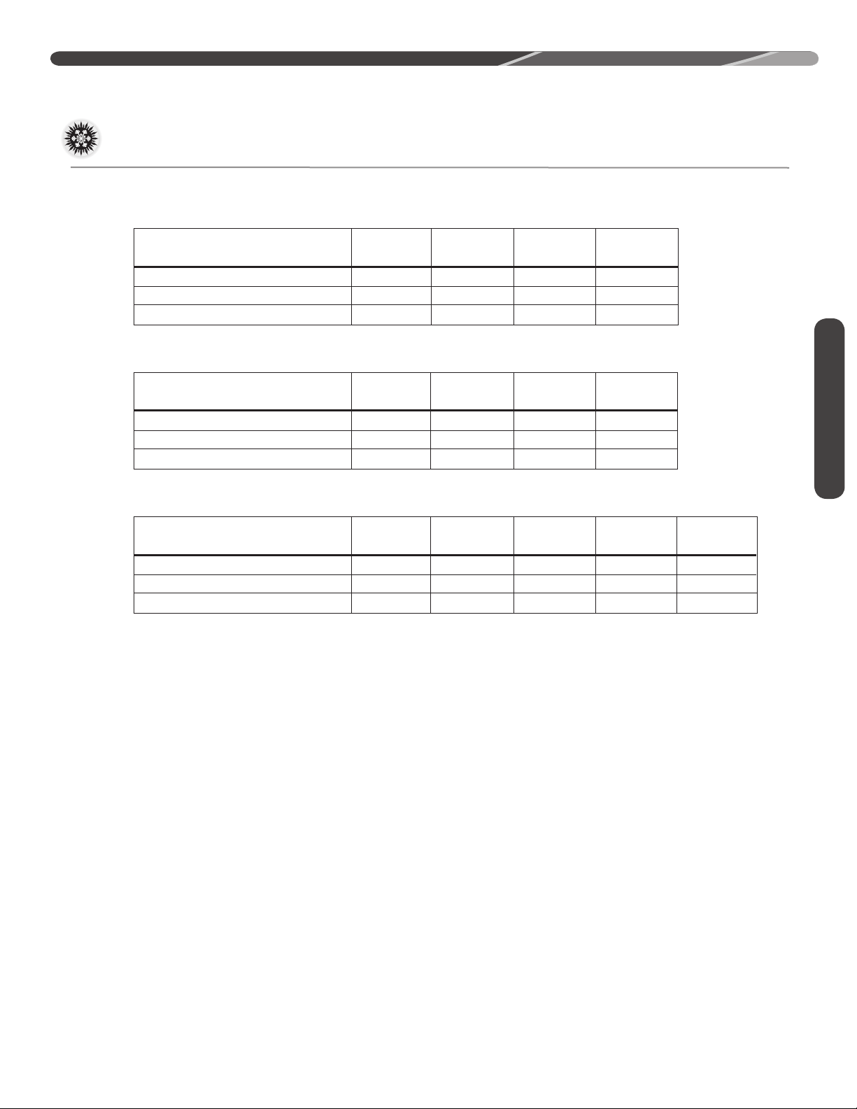
Page 5
GENERAL INFORMATION
Model
Number
Voltage
Phase
Freq
Rated Load
Amperes
(RLA)
Locked Rotor
Amperes
(LRA)
Fan
Motor
Full
Load
Amperes
(FLA)
Minimum
Circuit
Ampacity
Amperes
Minimum
Amperes
Maximum
Amperes
Face
Area
Sq. Ft .
[m
2
]
No.
Rows
CFM
[L/s]
Refrig .
Per
Circuit
(oz.)
[g]
Net
Lbs.
[kg]
Shipping
Lbs. [kg]
Fuse or HACR
Circuit Breaker
Outdoor Coil WeightCompressor
ELECTRICAL PHYSICAL
RP1418AJ1NA 208-230 1 60 9/9 48.0 0.70 12/12 20/20 15/15 9.06 [0.84] 1 2411 [1137] 97 [2750] 149 [67.6] 156 [70.8]
RP1424AJ1NA 208-230 1 60 12.8/12.8 58.3 0.70 17/17 25/25 20/20 9.06 [0.84] 1 2411 [1137] 89 [2523] 144 [65.3] 151 [68.5]
RP1430AJ1NA 208-230 1 60 14.1/14.1 73.0 0.70 19/19 30/30 25/25 11.14 [1.03] 1 2535 [1196] 106 [3005] 155 [70.3] 162 [73.5]
RP1436AJ1NA 208-230 1 60 15.4/15.4 83.9 0.60 20/20 35/35 25/25 14.82 [1.38] 1 3333 [1573] 111 [3146] 171 [77.6] 178 [80.7]
RP1442AJ1NA 208-230 1 60 17.9/17.9 112.0 0.90 24/24 40/40 30/30 14.82 [1.38] 1 2943 [1389] 155 [4394] 201 [91.2] 208 [94.3]
RP1448AJ1NA 208-230 1 60 19.6/19.6 130.0 1.20 26/26 45/45 35/35 19.76 [1.82] 1 4055 [1913] 143 [4054] 227 [103.0] 234 [106.1]
RP1460AJ1NA 208/230 1 60 23.7/23.7 152.5 1.00 31/31 50/50 40/40 24.23 [2.25] 1 4780 [2255] 232 [6577] 262 [118.8] 269 [122.0]
RP1436AC1NA 208-230 3 60 10.4 73.0 0.80 14 24.3 16.5 14.82 [1.38] 1 3333 [1573] 111 [3146] 171 [77.6] 178 [80.7]
RP1442AC1NA 208-230 3 60 13.5 88.0 1.00 18 31.4 21.3 14.82 [1.38] 1 2943 [1389] 155 [4394] 201 [91.2] 208 [94.3]
RP1448AC1NA 208-230 3 60 13.7 83.1 1.20 19 32.1 21.8 19.76 [1.84] 1 4055 [1913] 143 [4054] 227 [103.0] 234 [106.1]
RP1460AC1NA 208-230 3 60 15.9 110.0 1.00 21 36.8 24.8 24.23 [2.25] 1 4780 [2255] 232 [6577] 262 [118.8] 269 [122.0]
RP1436AD1NA 460 3 60 5.8 38.0 0.50 8 13.5 9.2 14.82 [1.38] 1 3333 [1573] 111 [3146] 171 [77.6] 178 [80.7]
RP1442AD1NA 460 3 60 6.0 44.0 0.50 8 13.9 9.4 14.82 [1.38] 1 2943 [1389] 155 [4394] 201 [91.2] 208 [94.3]
RP1448AD1NA 460 3 60 6.2 41.0 0.60 9 14.6 9.9 19.76 [1.84] 1 4055 [1913] 143 [4054] 227 [103.0] 234 [106.1]
RP1460AD1NA 460 3 60 7.1 52.0 0.50 10 16.4 11.1 24.23 [2.25] 1 4780 [2255] 232 [6577] 262 [118.8] 269 [122.0]
Model
Number
Voltage
Phase
Freq
Rated Load
Amperes
(RLA)
Locked Rotor
Amperes
(LRA)
Fan
Motor
Full
Load
Amperes
(FLA)
Minimu m
Circuit
Ampacity
Amperes
Minimu m
Amperes
Maximum
Amperes
Face
Area
Sq. Ft .
[m
2
]
No.
Rows
CFM
[L/s]
Refrig .
Per
Circuit
(oz.)
[g]
Net
Lbs.
[kg]
Shipping
Lbs. [kg]
Fuse or HACR
Circuit Breaker
Outdoor Coil We ightCompressor
ELECTRICAL PHYSICAL
RP1518AJ1NA 208-230 1 60 9/ 9 48.0 0.70 12/12 20/20 15/15 9.06 [0.84] 1 2411 [1137] 97 [2750] 123 [55.8] 130 [59.0]
RP1524AJ1NA 208-230 1 60 12.8/12.8 58.3 0.70 17/17 25/25 20/20 11.14 [1.03] 1 2411 [1137] 88 [2495] 131 [59.4] 138 [62.6]
RP1530AJ1NA 208-230 1 60 14.1/14.1 73.0 1.00 19/19 30/30 25/25 17.29 [1.61] 1 3840 [1812] 122 [3459] 160 [72.6] 167 [75.7]
15.4/15.4
83.9 2.80
22/22
35/35
30/30 19.76 [1.84]
3889 [1835] 118 [3345]
172 [78.0]
179 [81.2]
RP1542AJ1NA
208-230 1 60
17.9/17.9
112.0 1.00
23/23
40/40 30/30
19.76 [1.84]
1
3773 [1781] 139 [3941]
180 [81.6] 187 [84.8]
RP1548AJ1NA
18.5/18.5
124.0 2.80
26/26 40/40 35/35 24.23 [2.25]
5180 [2445] 188 [5330]
208 [94.3]
215 [97.5]
RP1560AJ1NA
208-230 1 60
23.7/23.7
152.5
1.00
31/31
50/50
40/40 28.26 [2.62]
1
3654 [1724] 212 [6010]
236 [107.0] 243 [110.2]
RP1536AJ1NA
208-230 1 60
208-230 1 60
1
1
RP1536AC1NA 208-230 3 60 1
10.4
73.0 2.80
16/16
20/20
25/25
19.76 [1.84]
3121 [1472] 124 [3515] 172 [78.0]
179 [81.2]
208-230 3 60 1 RP1542AC1NA
13.5
88.0
1.00 18/18
25/25 30/30 19.76 [1.84] 3815 [1800]
145 [4110]
180 [81.6] 187 [84.8]
RP1548AC1NA
208-230 3 60
13.8
83.11 2.80
21/21
25/25 30/30 24.23 [2.25]
4379 [2066] 194 [5500]
208 [94.3] 215 [97.5]
RP1560AC1NA
208-230 3 60
15.9
110.0
1 1.00 21/21
25/25 35/35
28.26 [2.62]
3654 [1724] 223 [6321]
236 [107.0] 243 [110.2]
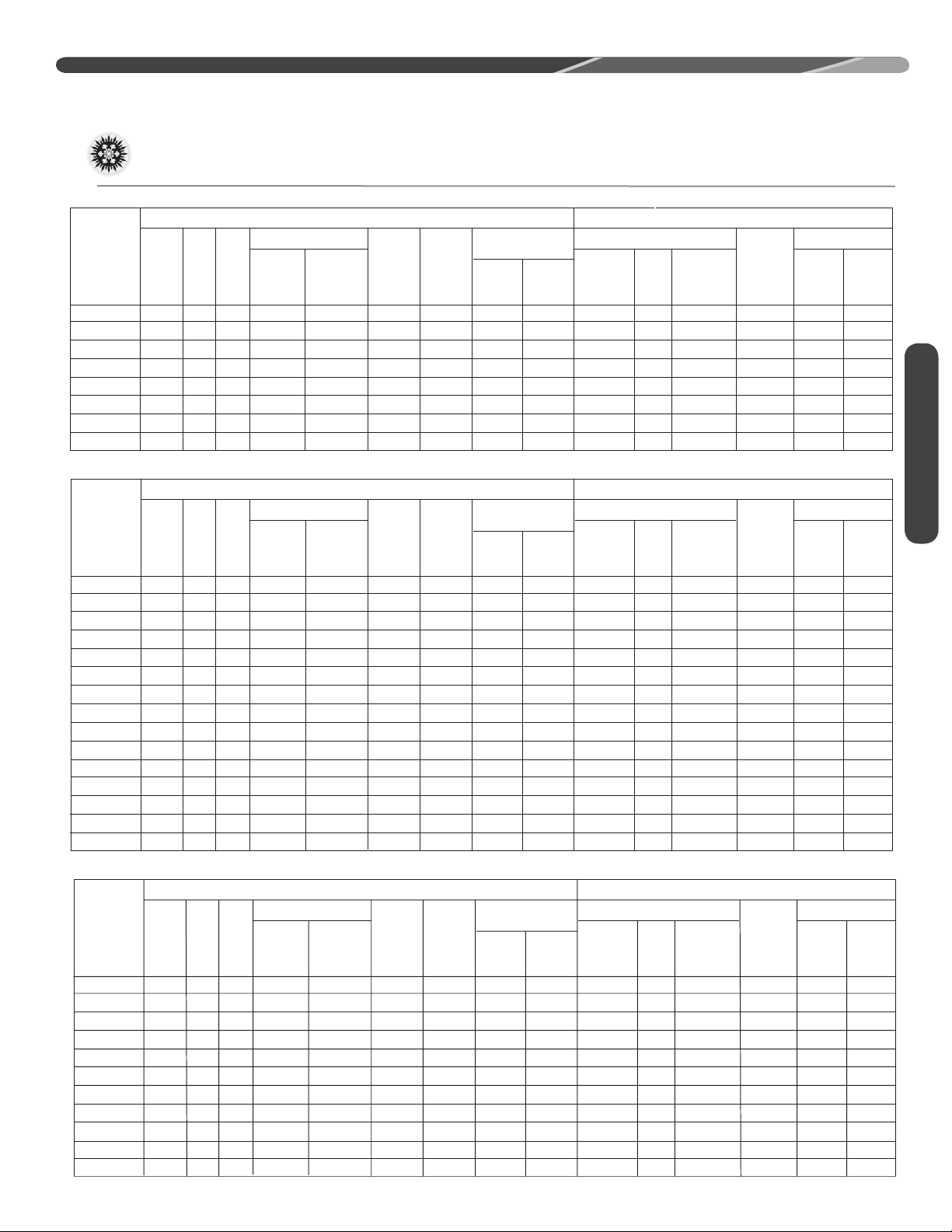
Electrical and Physical Data
RP13
ELECTRICAL PHYSICAL
Fan
Model
Number
RP1336AC1NA 208-230 3 60 10.4 73.0 0.80 14 24.3 16.5 14.82 [1.38] 1 3333 [1573] 111 [3146] 171 [77.6] 178 [80.7]
RP1342AC1NA 208-230 3 60 13.5 88.0 1.00 18 31.4 21.3 14.82 [1.38] 1 2943 [1389] 201 [91.2] 208 [94.3]
RP1348AC1NA 208-230 3 60 13.7 83.1 1.20 19 32.1 21.8 19.76 [1.84] 1 4055 [1913]
RP1360AC1NA 208-230 3 60 15.9 110.0 1.00 21 36.8 24.8 24.23 [2.25] 1 4780 [2255]
RP1336AD1NA 460 3 60 5.8 38.0 0.50 8 13.5 9.2 14.82 [1.38] 1 3333 [1573]
RP1342AD1NA 460
RP1348AD1NA 460
RP1360AD1NA 460
Voltage
Phase
3 60 6.0 44.0
3 60
3 60
Rated Load
Freq
Amperes
6.2 41.0 0.60
7.1 52.0 0.50
(RLA)
Locked Rotor
Amperes
(LRA)
Amperes
0.50
Motor
Full
Load
(FLA)
Minimum
Circuit
Ampacity
Amperes
8
9
10
Fuse or HACR
Circuit Breaker
Minimum
Amperes
13.9
14.6
16.4
Maximum
Amperes
9.4
9.9
11.1
14.82 [1.38]
19.76 [1.84]
24.23 [2.25]
RP14
Face
Area
Sq. Ft .
[m
Outdoor Coil We ightCompressor
No.
Rows
2
]
CFM
[L/s]
1
2943 [1389]
1
4055 [1913]
1
4780 [2255]
Refrig .
Per
Circuit
(oz.)
[g]
155 [4394]
143 [4054]
232 [6577]
111 [3146]
155 [4394]
143 [4054]
232 [65717]
227 [103.0] 234 [106.1]
262 [118.8] 269 [122.0]
171 [77.6] 178 [80.7]
Net
Lbs.
[kg]
201 [91.2]
227 [103.0]
262 [118.8]
Shipping
Lbs. [kg]
208 [94.3]
234 [106.1]
269 [122.0]
General Information
RP15
5
Page 6
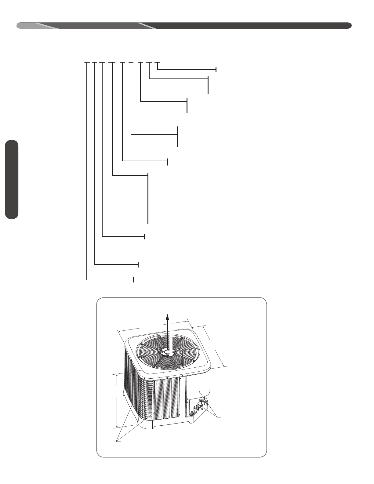
“ L”
“W”
“H”
A
I
R
D
I
S
C
H
A
R
G
E
ALLOW 60” [1524mm]
OF CLEARANCE
AIR INLET LOUVERS ALLOW
6” [152mm] Min. OF CLEARANCE ALL SIDES
12” [305mm] RECCOMMENDED
SERVICE PANELS/
INLET CONNECTIONS / HIGH & LOW
VOLTAGE ACCESS
ALLOW 24” [ 610 mm] OF CLEARANCE
ST-A1226-02-00
R P 14 24 A J 1 N A
MINOR SERIES
Z
TYPE
1 - SINGLE STAGE P - PISTON
VOLTAGE
J = 1 PH, 208-230/60
C = 3 PH, 208-230/60
D = 3 PH, 460/60
MAJOR SERIES
CAPACITY
18 = 18000 BTU/HR [5.28 kW]
24 = 24000 BTU/HR [7.03 kW]
30 = 30000 BTU/HR [8.79 kW]
36 = 36000 BTU/HR [10.55 kW]
42 = 42000 BTU/HR [12.31 kW]
48 = 48000 BTU/HR [14.07 kW]
60 = 60000 BTU/HR [17.58 kW]
13 SEER
14 SEER
15 SEER
HEAT PUMP
BRAND
CONTROLS
C - COMMUNICATING
N - NON-COMMUNICATING
GENERAL INFORMATION
General Information
6
ALLOW 60" [1524mm] OF
CLEARANCE
AIR INLET LOUVERS ALLOW
6" [152 mm] OF CLEARANCE ALL SIDES
12" [305 mm] RECOMMENDED
SERVICE PANELS/
INLET CONNECTIONS /
HIGH & LOW VOLTAGE
ACCESS ALLOW
24" [610 mm] OF
CLEARANCE
Page 7
Specifications
GENERAL INFORMATION
DIMENSIONAL DATA
Height “H” inches (mm)
Length “L” inches (mm)
Width “W” inches (mm)
Height “H” inches (mm)
Length “L” inches (mm)
Width “W” inches (mm)
Height “H” inches (mm)
Length “L” inches (mm)
Width “W” inches (mm)
RP13
RP14
RP15
18, 24, 30
25 (635)27 (686)39 (991)35 (889)
29.75 (756)33.75 (857) 35.75 (908)33.75 (857)
29.75 (756)
18, 24, 30
25 (635) 27 (686)39 (991)35 (889)
29.75 (756)33.75 (857) 35.75 (908)33.75 (857)
29.75 (756)
18, 24 30 36, 42 48 60
25 (635) 27 (686) 27 (686) 31 (787) 35 (889)
29.75 (756) 29.75 (756) 33.75 (857) 33.75 (857) 35.75 (908)
29.75 (756) 29.75 (756) 33.75 (857) 33.75 (857) 35.75 (908)
36, 42 6048
33.75 (857)
36, 42 6048
33.75 (857)
35.75 (908)33.75 (857)
35.75 (908)33.75 (857)
General Information
Proper Installation
Proper sizing and installation of this equipment is
critical to achieve optimal performance� Use the
information in this Installation Instruction Manual
and reference the applicable manufacturer’s
specification sheet when installing this product�
IMPORTANT: This product has been
designed and manufactured to meet ENERGY
STAR criteria for energy efficiency when matched
with appropriate indoor components� However,
proper refrigerant charge and proper airflow are
critical to achieve rated capacity and efficiency�
Installation of this product should follow the
manufacturer’s refrigerant charging and airflow
instructions� Failure to confirm proper charge
and airflow may reduce energy efficiency and
shorten equipment life�
MATCH ALL COMPONENTS:
• OUTDOOR UNIT
• INDOOR COIL
• INDOOR AIR HANDLER/FURNACE
• REFRIGERANT LINES
• INDOOR THERMOSTAT
7
Page 8

INSTALLATION
Choosing a Location
Location
IMPORTANT:
national building codes and ordinances for special
installation requirements� Following location
information will provide longer life and simplified
servicing of the outdoor heat pump�
Consult local and
NOTICE: These units must be installed
outdoors� No ductwork can be attached, or
other modifications made, to the discharge grille�
Modifications will affect performance or operation�
Operational Issues
IMPORTANT: Locate the unit
in a manner that will not prevent, impair, or
compromise the performance of other equipment
installed in proximity to the unit� Maintain all
required minimum distances to gas and electric
meters, dryer vents, and exhaust and inlet
openings� In the absence of national codes or
manufacturers’ recommendations, local code
recommendations and requirements will take
precedence�
• Refrigerant piping and wiring should be properly
sized and kept as short as possible to avoid
capacity losses and increased operating costs�
• Locate the unit where water runoff will not create
a problem with the equipment� Position the unit
away from the drip edge of the roof whenever
possible� Units are weatherized, but can be
affected by the following:
• Water pouring into the unit from the junction
of rooflines, without protective guttering�
Large volumes of water entering the heat
pump while in operation can impact fan blade
or motor life, and coil damage may occur to a
heat pump if moisture cannot drain from the
unit under freezing conditions�
• Freezing moisture or sleeting conditions can
cause the cabinet to ice-over prematurely
and prevent heat pump operation, requiring
backup heat, which generally results in less
economical operation�
• Closely follow the clearance recommendations
on page 8�
• 24" [61.0 cm] to the service panel access
• 60" [152.4 cm] above heat pump fan
discharge (unit top) to prevent recirculation
• 6" [15.2 cm] to heat pump coil grille air inlets
with 12" [30.5 cm] minimum recommended
Corrosive Environment
The metal parts of this unit may be subject to
rust or deterioration if exposed to a corrosive
environment� This oxidation could shorten the
equipment’s useful life�
Corrosive elements include, but are not limited to,
salt spray, fog or mist in seacoast areas, sulphur or
chlorine from lawn watering systems, and various
chemical contaminants from industries such as
paper mills and petroleum refineries�
If the unit is to be installed in an area where
contaminants are likely to be a problem, special
attention should be given to the equipment
location and exposure�
• Avoid having lawn sprinkler heads spray directly
on the unit cabinet�
• In coastal areas, locate the unit on the side of
the building away from the waterfront�
• Shielding provided by a fence or shrubs may
give some protection, but cannot violate
minimum airflow and service access clearances�
• Elevating the unit off its slab or base enough to
allow air circulation will help avoid holding water
against the base pan�
WARNING: Disconnect all power
to unit before starting maintenance� Failure to do
so can cause electrical shock resulting in severe
personal injury or death�
Regular maintenance will reduce the buildup of
contaminants and help to protect the unit’s finish�
• Frequent washing of the cabinet, fan blade, and
coil with fresh water will remove most of the salt
or other contaminants that build up on the unit�
• Regular cleaning and waxing of the cabinet with
a good automobile polish will provide some
protection�
• A good liquid cleaner may be used several times
a year to remove matter that will not wash off
with water�
8
Page 9
INSTALLATION
SERVICE PANELS/
INLET CONNECTIONS
/ HIGH & LOW
VOLTAGE ACCESS
ALLOW 24” [610 mm] OF
CLEARANCE
ALLOW 60” [1524 mm]
OF CLEARANCE
AIR INLET LOUVERS ALLOW
6” [152 mm] Min. OF
CLEARANCE ALL SIDES
12” [305 mm] RECOMMENDED
ST-A1226-04-00
6" MIN. (152 mm) FOR 1.5 & 2 TON
9" MIN. (229 mm) FOR 2.5-5 TON
24" MIN. (610 mm)
ST-A1226-03-00
ELEVATE ABOVE
ANTICIPATE HIGH
SNOW FALL
DO NOT BLOCK
OPENINGS
IN BASE PAN
BASE PAD
(CONCRETE OR OTHER SUITABLE
MATERIAL)
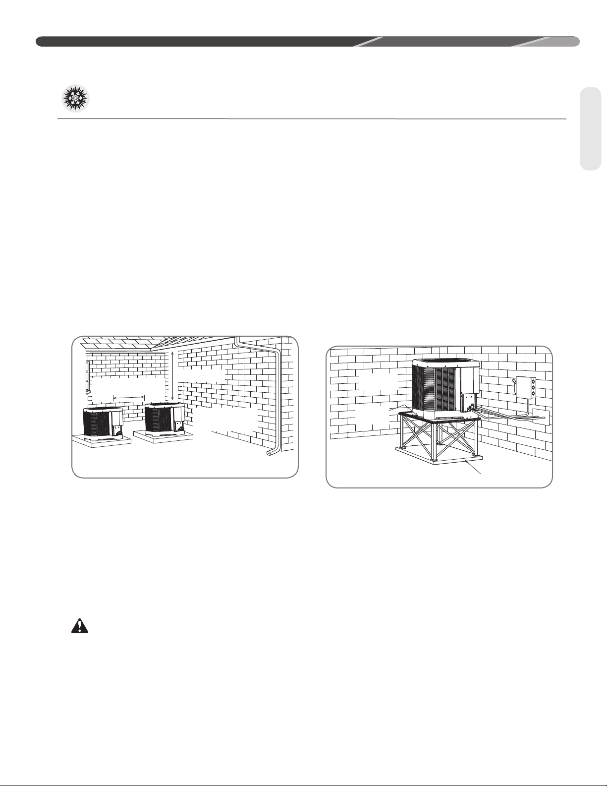
Choosing a Location (cont�)
For Units With Space
Limitations
In the event that a space limitation exists, we will
permit the following clearances:
Single-Unit Applications: Clearances below 6"
[15.2 cm] will reduce unit capacity and efficiency.
Do not reduce the 60" [152.4 cm] discharge or the
24" [61.0 cm] service clearances.
Multiple-Unit Applications: When multiple
condenser grille sides are aligned, a 6" [15.2
cm] clearance is recommended for 1.5 and 2
ton models and 9" [22.9 cm] for 2.5 ton to 5 ton
models� Two combined clearances below the
minimum will reduce capacity and efficiency� Do
not reduce the 60" [152.4 cm] discharge or 24"
[61.0 cm] service clearances.
Location
• If elevating a unit on a flat roof, use 4" x 4"
[10.2 cm x 10.2 cm] or equivalent stringers
positioned to distribute unit weight evenly and
prevent noise and vibration�
• Where snowfall is anticipated, raise the unit
above the base pad to prevent ice buildup and
coil damage� Mount the unit high enough to be
above the average accumulated area snowfall�
See “Ground Snow Depth” chart on page 9 for
representative snow depths�
NOTICE: Do not block drain openings on
bottom of unit�
• If unit must be elevated because of anticipated
snowfall, secure unit and elevating stand such
that unit and/or stand will not tip over or fall off�
Keep in mind that someone may try to climb on
unit�
Customer Satisfaction Issues
• The heat pump should be located away from the
living, sleeping, and recreational spaces of the
owner and those spaces on adjoining property�
• To prevent noise transmission, the mounting pad
for the outdoor unit should not be connected to
the structure and should be located a sufficient
distance above grade to prevent ground water
from entering the unit�
Unit Mounting
WARNING: Secure an elevated unit
and its elevating stand in order to prevent tipping�
Failure to do so may result in severe personal
injury or death�
Elevation of Unit
If elevating the heat pump, either on a flat roof or
on a slab, observe the following guidelines�
Factory-Preferred Tie-Down
Method for High Wind or
Seismic Loads
IMPORTANT: The manufacturer-
approved/recommended method is a guide to
securing equipment for wind and seismic loads�
Other methods might provide the same result, but
the manufacturer method is the only one endorsed
by the manufacturer for securing equipment where
wind or earthquake damage can occur� Additional
information is available in the PTS (Product
Technical Support) section of the manufacturer’s
Web sites Rheemote�net, MyRheem�com, or
MyRuud�com and can be found as a listing under
each outdoor model� If you do not have access to
this site, your distributor can offer assistance�
9
Page 10

INSTALLATION
Choosing a Location (cont�)
Location
ALABAMA INDIANA MINNESOTA NEW MEXICO PENNSYLVANIA VIRGINIA
Huntsville 7 Evansville 12 Duluth 64 Albuquerque 4 Allentown 23 Dulles Airport 19
ARIZONA
Flagstaff 48 Indianapolis 21
Prescott 3 South Bend 44 Rochester 50
Winslow 7
ARKANSAS
Ft. Smith 5 Des Moines 22 Jackson 3 Buffalo 42 Williamsport 20
Little Rock 6 Dubuque 38 MISSOURI
CALIFORNIA
Blue Canyon 25 Waterloo 36 Kansas City 18 Rochester 38
Mt. Shasta 69
COLORADO
Alamosa 15 Dodge City 12
Colorado Springs 14 Goodland 14 Billings 17 Cape Hattaras 5 Aberdeen 42
Denver 15 Topeka 19 Glasgow 17 Charlotte 10 Huron 43 Beckley 51
Grand Junction 16 Wichita 11 Great Falls 16 Greensboro 11 Rapid City 14 Charleston 20
Pueblo 7
CONNECTICUT
Bridgeport 23 Lexington 12 Kalispell 53 Winston-Salem 17 Bristol 8
Hartford 29 Louisville 11 Missoula 23
New Haven 15
DELAWARE
Wilmington 13 Portland 62 Lincoln 20 Williston 25 Nashville 8 Milwaukee 32
GEORGIA MARYLAND
Athens 5 Baltimore 17 North Platte 15 Akron-Canton 15 Abilene 6 Casper 10
Macon 8
IDAHO
Boise 6 Nantucket 18 Valentine 22 Dayton 11 El Paso 5 Sheridan 25
Lewiston 9 Worcester 35
0 Pocatello 7
ILLINOIS
Chicago O’Hare 18 Detroit City 9 Reno 11
Chicago 22 Detroit Airport 17 Winnemucca 6 Oklahoma City 5 Wichita Falls 5
Moline 17
Peoria 16 Flint 28 Concord 66
Rockford 25 Grand Rapids 37
Springfield 23 Houghton Lake 56 Atlantic City 11 Eugene 17 Wendover 3
NOTICE:
Local records and experience must be considered when establishing the unit installation height� There is a 2% probability that
Fort Wayne 17 International Falls 43 Clayton 10 Erie 19 Lynchburg 16
IOWA
Burlington 17
Sioux City 33 Columbia 21
KANSAS
Concordia 23 Springfield 14
KENTUCKY
Covington 12 Helena 18 Wilmington 9
MAINE NEBRASKA
Caribou 100 Grand Island 30 Fargo 34 Memphis 5 Madison 32
MASSACHUSETTS
Boston 30 Scottsbluff 11 Columbus 10 Dallas 3 Lander 20
MICHIGAN
Alpena 53 Ely 9 Youngstown 12 Midland 2
Detroit – Willow Run
Lansing 42 Newark 15 Medford 8
Marquette 53 Pendleton 11 Burlington 37
Muskegon 43 Portland 10
Sault Ste. Marie 80 Salem 7
the ground snow depth shown in this table will be exceeded annually� Drifts have not been considered� This data represents 184
10
National Weather Service locations at which measurements are made and assumes a nationwide snow density of 12 lb�/ft�
GROUND SNOW DEPTH – INCHES
Minneapolis/St. Paul
St. Cloud 53 Albany 25 Pittsburgh 22 Richmond 12
MISSISSIPPI
St. Louis 16 Syracuse 35 Columbia 12 Spokane 41
MONTANA
Havre 24 Raleigh-Durham 10 Sioux Falls 38 Elkins 21
Norfolk 29
Omaha 20 Cleveland 16 Amarillo 10 Cheyenne 15
NEVADA
Elko 20 Toledo Express 8 Lubbock 10
NEW HAMPSHIRE
21
NEW JERSEY
50 Roswell 8 Harrisburg 23 National Airport 18
NEW YORK
Binghamton 35 Scranton 16 Roanoke 17
NYC – Kennedy Airport 18
NYC – LaGuardia Airport 18
NORTH CAROLINA
Asheville 12
NORTH DAKOTA
Bismarck 25 Knoxville 8 La Crosse 32
OHIO TEXAS WYOMING
Mansfield 17 Fort Worth 6
OKLAHOMA
Tulsa 8
OREGON
Burns City 24 Salt Lake City 8
Philadelphia 16 Norfolk 9
WASHINGTON
RHODE ISLAND
Providence 21 Quillayute 24
SOUTH CAROLINA
Greenville 4 Stampede Pass 51
SOUTH DAKOTA
TENNESSEE
Chattanooga 6 Green Bay 36
San Antonio 3
UTAH
Milford 16
VERMONT
Olympia 24
Seattle-Tacoma 14
Yakima 25
WEST VIRGINIA
Huntington 15
WISCONSIN
3
Page 11
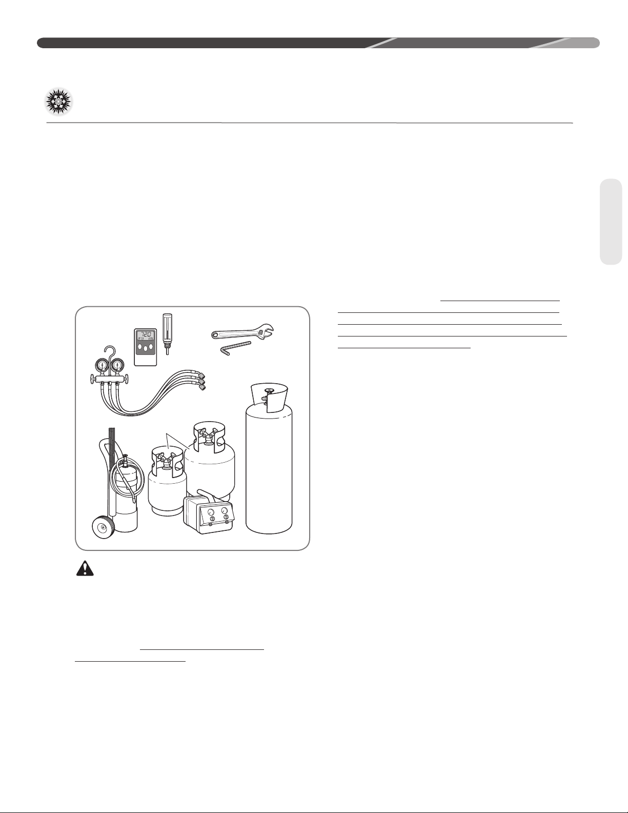
Tools and Refrigerant
Ambient and Tube
Thermometers
Manifold
Gauge
Set
Brazing
Rods
Torch Nitrogen
Reclaimer
Recovery
Cylinders
Allen Wrench
Crescent Wrench
INSTALLATION
Tools Required for Installing
and Servicing R-410A Models
Manifold Sets:
– Up to 800 PSIG High-Side
– Up to 250 PSIG Low-Side
– 550 PSIG Low-Side Retard
Manifold Hoses:
– Service Pressure Rating of 800 PSIG
Recovery Cylinders:
– 400 PSIG Pressure Rating
– Dept� of Transportation 4BA400 or BW400
CAUTION: R-410A systems operate
at higher pressures than R-22 systems� Do not
use R-22 service equipment or components on
R-410A equipment�
Specifications of R-410A
Application: R-410A is not a drop-in
replacement for R-22� Equipment designs must
accommodate its higher pressures� It cannot be
retrofitted into R-22 heat pumps�
Physical Properties: R-410A has an atmospheric
boiling point of -62.9°F [-52.7°C] and its saturation
pressure at 77°F [25°C] is 224.5 psig.
Composition: R-410A is a near-azeotropic
mixture of 50% by weight difluoromethane (HFC-
32) and 50% by weight pentafluoroethane (HFC-
125)�
Pressure: The pressure of R-410A is
approximately 60% (1�6 times) greater than
R-22� Recovery and recycle equipment, pumps,
hoses, and the like must have design pressure
ratings appropriate for R-410A� Manifold sets
need to range up to 800 psig high-side and 250
psig low-side with a 550 psig low-side retard.
Hoses need to have a service pressure rating of
800 psig. Recovery cylinders need to have a 400
psig service pressure rating, DOT 4BA400 or DOT
BW400.
Combustibility: At pressures above 1
atmosphere, a mixture of R-410A and air can
become combustible� R-410A and air should
never be mixed in tanks or supply lines or
be allowed to accumulate in storage tanks�
Leak checking should never be done with a
mixture of R-410A and air� Leak-checking can
be performed safely with nitrogen or a mixture of
R-410A and nitrogen�
Quick-Reference Guide For
R-410A
• R-410A refrigerant operates at approximately
60% higher pressure (1�6 times) than R-22�
Ensure that servicing equipment is designed to
operate with R-410A�
• R-410A refrigerant cylinders are light rose in
color�
• R-410A, as with other HFCs, is only compatible
with POE oils�
• Vacuum pumps will not remove moisture from
POE oil used in R-410A systems�
• R-410A systems are to be charged with liquid
refrigerants� Prior to March 1999, R-410A
refrigerant cylinders had a dip tube� These
cylinders should be kept upright for equipment
charging� Post-March 1999 cylinders do not
have a dip tube and should be inverted to ensure
liquid charging of the equipment�
• Do not install a suction line filter drier in the
liquid line�
• A factory-approved biflow liquid line filter drier
is shipped with every unit and must be installed
in the liquid line at the time of installation� Only
manufacturer-approved liquid line filter driers can
be used� These are Sporlan (CW083S) and Alco
(80K083S) driers� These filter driers are rated for
minimum working pressure of 600 psig� The filter
drier will only have adequate moisture-holding
capacity if the system is properly evacuated�
• Desiccant (drying agent) must be compatible for
POE oils and R-410A refrigerant�
Tools
11
Page 12
INSTALLATION
Replacement Units
Tubing
To prevent failure of a new unit, the existing line set
must be correctly sized and cleaned or replaced�
Care must be exercised that the expansion device
is not plugged� For new and replacement units, a
liquid line filter drier must be installed and refrigerant
tubing must be properly sized� Test the oil for acid� If
positive, a suction line filter drier is mandatory�
Indoor Coil
CAUTION: Only use evaporators
approved for use on R-410A systems that are
specifically matched with the outdoor unit per
the manufacturer’s specification sheets� Use
of existing R-22 evaporators can introduce
mineral oil to the R-410A refrigerant, forming two
different liquids and decreasing oil return to the
compressor� This can result in compressor failure�
REFER TO INDOOR COIL MANUFACTURER’S
INSTALLATION INSTRUCTIONS.
IMPORTANT: The manufacturer is not
responsible for the performance and operation of
a mismatched system or for a match listed with
another manufacturer’s coil�
NOTICE: All outdoor units must be
installed with a matched TXV indoor coil� Refer to
manufacturer’s outdoor unit specification sheet for
approved indoor coils�
IMPORTANT: When replacing an
R-22 unit with an R-410A unit, either replace
the line set or ensure that residual mineral oil is
drained from existing lines including oil trapped in
low spots�
The thermostatic expansion valve in the
matching coil is specifically designed to operate
with R-410A� DO NOT use an R-22 TXV or
evaporator� The existing evaporator must
be replaced with the factory-specified TXV
evaporator specifically designed for R-410A�
Location
Do not install the indoor coil in the return duct
system of a gas or oil furnace� Provide a service
inlet to the coil for inspection and cleaning� Keep
the coil pitched toward the drain connection�
CAUTION: When coil is installed
over a finished ceiling and/or living area, it is
required that a secondary condensate pan be
installed under entire unit� Failure to do so can
result in property damage�
12
Interconnecting Tubing
The purpose of this section is to specify the
best construction/sizing practices for installing
interconnection tubing between the indoor and
outdoor unit�
Refrigerant Level Adjustment
All units are factory-charged with R-410A
refrigerant to cover 15 feet of standard size
interconnecting liquid and vapor lines with a
required field installed filter drier� Adjustment of
charge may be necessary even if the application
has exactly 15 feet of line set due to other
installation variables such as pressure drop,
vertical lift, and indoor coil size� For different
lengths, adjust the charge as indicated below�
• 1/4" ± .3 oz./foot [6.4 mm ± 8.5 g/.30 m]
• 5/16" ± .4 oz./foot [7.9 mm ± 11.3 g/.30 m]
• 3/8" ± .6 oz./foot [9.5 mm ± 17.0 g/.30 m]
• 1/2" ± 1.2 oz./foot [12.7 mm ± 34.0 g/.30 m]
• 6 oz. required factory supplied field-installed
• filter drier�
Charge Adjustment = (Line Set (oz./ft.) x Total
Length) – Factory Charge for Line Set
Example: A three ton heat pump unit with factory
installed 3/8” liquid service valve requires 75 ft. of
line set with a liquid line diameter of 1/2”.
Factory Charge for Line Set = 15 ft. x .6 oz. = 9 oz.
Charge Adjustment = (1.2 oz. x 75 ft.) – 9 oz. =
+ 81 oz.
Page 13
Interconnecting Tubing (cont�)
INSTALLATION
Interconnecting Tubing and
Fitting Losses
Refrigerant tubing is measured in terms of actual
length and equivalent length� Actual length is used
for refrigerant charge applications� Equivalent
length takes into account pressure losses from
Table 1
Equivalent Length for Fings ()
90° Short
Line Size
(in)
3/8 1.3 0.8 0.3 6 4 0.4 6
1/2 1.4 0.9 0.4 9 5 0.6 6
5/8 1.5 1 0.5 12 6 0.8 6
3/4 1.9 1.3 0.6 14 7 0.9 6
7/8 2.3 1.5 0.7 15 8 1 6
1-1/8 2.7 1.8 0.9 22 12 1.5 6
Radius
Elbow
90° Long
Radius
Elbow
45°
Elbow
Liquid Line Selection
The purpose of the liquid line is to transport warm
sub-cooled liquid refrigerant from the outdoor unit
to the indoor unit� It is important not to allow the
refrigerant to ash any superheated vapor prior
to the expansion device of the indoor coil� The
ashing of refrigerant can occur for the following
reasons:
• Low refrigerant charge
• Improperly selected liquid line size
• Absorption of heat prior to expansion device
• Excessive vertical rise between the condenser
and evaporator
Table 2 lists the equivalent length per 25’ of liquid
line at various diameters up to 300’� The total pres-
tubing length, ttings, vertical separation, accessories, and lter dryers. The table below references
dierent commonly used equivalent lengths.
Solenoid
Valve
sure drop allowed for the liquid line is 50 PSI� The
procedure for selecting the proper liquid line is as
follows:
• Measure the total amount of vertical rise
• Measure the total amount of liquid line needed
• Add all of the equivalent lengths associated with
any ttings or accessories using the table above.
• Add the total length and tting pressure drop.
This will equal your total equivalent length�
• Round-down the total equivalent length to the
closest value in Table 2�
• Reference Table 2 to verify the rounded-down
value of the calculated equivalent length is compatible with the required vertical rise and diameter of liquid line�
Check
Valve
Site
Glass
Filter
Dryer
Tubing
Note: Elevaon is defined as the
highest point of the line set to the
lowest
13
Page 14
INSTALLATION
OD Model
Compressor
Name Plate Oil
Charge (oz)
RP1336AC
ZP31K5E-TF5-13R 42
RP1342AC
ZP36K5E-TF5-13R 42
RP1348AC
ZP42K5E-TF5-13R 42
RP1360AC
ZP49K6E-TF5-130 42
RP1336AD
ZP31K5E-TFD-13R 42
RP1342AD
ZP36K5E-TFD-13R 42
RP1348AD
ZP42K5E-TFD-13R 42
RP1360AD
42ZP49K6E-TFD-130
Interconnecting Tubing (cont�)
Example: A 3-Ton heat pump unit is installed 50’
below the ID unit, requires a 75’ of 1/2” diameter
liquid line, and 4 90° LR elbows�
• Fitting Equivalent Length (ft.) = 4 x .9 = 3.6’
• Total Equivalent Length (ft.) = 75’ + 3.6’ = 78.6’
• Rounded-down value (ft.) = 75’
Liquid Line
R-410A
System
Capacity
Model
37 3/8" [9.53]
(Exerpt from Table 2, page 17)
Size
Connection
Size (Inch
I.D.) [mm]
Liquid Line
Size (Inch
O.D.) [mm]
1/4 [6.35] 25 [7.62]
5/16 [7.94] 25 [7.62] 50 [15.24] 60 [18.29] 45 [13.72] 35 [10.67] 20 [6.1] 5 [1.52]
3/8 [9.53] 25 [7.62] 50 [15.24] 75 [22.86] 80 [24.38] 80 [24.38] 75 [22.86] 70 [21.34] 65 [19.81] 60 [18.29] 55 [16.76] 50 [15.24] 45 [13.72]
7/16 [11.12] 25 [7.62] 50 [15.24] 75 [22.86] 95 [28.96] 90 [27.43] 90 [27.43] 85 [25.91] 85 [25.91] 85 [25.91] 80 [24.38] 80 [24.38] 80 [24.38]
1/2 [12.71] 25 [7.62] 50 [15.24] 75 [22.86] 95 [28.96] 95 [28.96] 95 [28.96] 95 [28.96] 95 [28.96] 95 [28.96] 90 [27.43] 90 [27.43] 90 [27.43]
25 [7.62] 50 [15.24] 75 [22.86] 100 [30.48] 125 [45.72] 150 [45.72] 175 [53.34] 200 [60.96] 225 [68.58] 250 [76.20] 275 [83.82] 300 [91.44]
N/R N/R N/R N/R N/R N/R N/R N/R N/R N/R N/R
Long Line Set Applications
Long line set applications are dened as applications that require accessories or alternate construction methods� The following are special considerations that need to be addressed when installing a
long line set application:
• Additional refrigerant charge
Tubing
• Fitting losses and maximum equivalent length
considerations
• Refrigerant migration during the o cycle
• Oil return to the compressor
• Capacity losses
• System oil level adjustment
This application is acceptable because the 50’
vertical rise is less than the maximum rise of 75’ for
this application� The application is also considered
to have a long line set� Reference the long line set
section of the I&O for detail�
Liquid Line Size
Elevation (Above or Below) Indoor Coil
Total
Maximum
Length - Feet [m]
Equivalent
Vertical Separation - Feet [m]
N/R N/R N/R N/R N/R
14
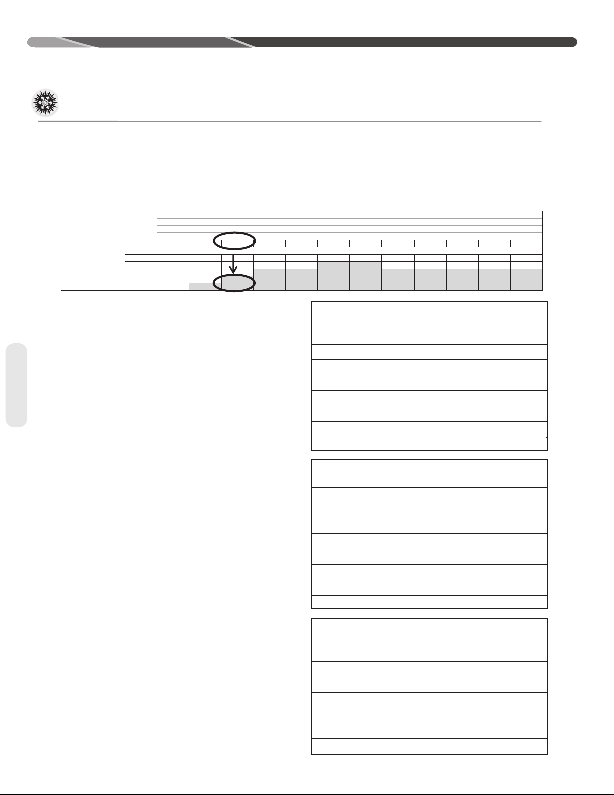
Table 2 is used to determine if the application is
considered to have a long line set� The region of
the chart that is shaded grey is considered to be
a long line set application.
Oil Level Adjustments for Long
Line Set Applications
Additional oil will need to be added for long line set
applications� (Ref� Table 2)� Below is the equation for
the oil level adjustment and the compressor name
plate oil charge for the dierent od units.
Oil to be Added = [(Charge Adjustment + OD
Unit Name Plate Charge (oz.)) x (0.022) – [(0.10) x
(Compressor Name Plate Oil Charge (oz.))]
Example: An application requires 125ft of line set
with a liquid line diameter of 3/8”, Charge Adjust-
ment = 52.4 oz., Name Plate Charge = 107 oz.,
Name Plate Oil Charge = 25 oz., Oil to be Added =
((52.4 oz. +107 oz.) x .022) – (.10 x 25 oz.) = 1.0 oz.
OD Model
RP1436AC
RP1442AC
RP1448AC
RP1460AC
RP1436AD
RP1442AD
RP1448AD
RP1460AD
OD Model
RP1418AJ
RP1442AJ
RP1430AJ
RP1436AJ
RP1442AJ
RP1448AJ
RP1460AJ
Compressor
Name Plate Oil
Charge (oz)
ZP31K5E-TF5-13R 42
ZP36K5E-TF5-13R 42
ZP42K5E-TF5-13R 42
ZP49K6E-TF5-130 42
ZP31K5E-TFD-13R 42
ZP36K5E-TFD-13R 42
ZP42K5E-TFD-13R 42
42ZP49K6E-TFD-130
Compressor
Name Plate Oil
Charge (oz)
ZP16K5E-PFV-13R 21
ZP21K6E-PFV-130 21
ZP25K5E-PFV-13R 25
ZP31K5E-PFV-13R 21
ZP36K5E-PFV-13R 42
ZP42K5E-PFV-13R 42
ZP49K6E-PFV-130 42
Page 15

Interconnecting Tubing (cont�)
INSTALLATION
OD Model
RP1518AJ
RP1524AJ
RP1530AJ
RP1536AJ
RP1542AJ
RP1548AJ
RP1560AJ
RP1536AC
RP1542AC
RP1548AC
RP1560AC
Compressor
ZP16K5E-PFV-13R 21
ZP21K5E-PFV-13R 21
ZP25K5E-PFV-13R 25
ZP31K6E-PFV-130 21
ZP36K5E-PFV-13R 42
ZP40K6E-PFV-130 42
ZP49K6E-PFV-130
ZP31K6E-TF5-130
ZP36K5E-TF5-13R
ZP40K6E-TF5-130
ZP49K6E-TF5-130
Name Plate Oil
Charge (oz)
42
21
42
42
42
Suction Line Selection
Purpose of the suction line is to return superheated
vapor to the condensing unit from the evaporator�
Proper suction line sizing is important because it
plays an important role in returning oil to the compressor to prevent potential damage to the bearings, valves, and scroll sets� Also, an improperly
sized suction line can dramatically reduce capacity
and performance of the system� The procedure for
selecting the proper suction line is as follows:
• The total amount of suction line needed
• Add all of the equivalent lengths associated with
any ttings or accessories using the table on
previous page�
• Add the total length and tting pressure drop.
This will equal your total equivalent length�
• Reference Table 2 to verify that the calculated
equivalent length falls within the compatibility
region of the chart�
• Verify Table 3 to verify the capacity dierence is
compatible with the application�
Refrigerant Migration During
Off Cycle
Long line set applications can require a considerable amount of additional refrigerant� This additional refrigerant needs to be managed throughout the
entire ambient operating envelope that the system
will go through during its life cycle. O-Cycle migration is where excess refrigerant condenses and
migrates to the lowest part of the system� Excessive build-up of refrigerant at the compressor will
result in poor reliability and noisy operation during
startup� This section demonstrates the required
accessories and unit conguration for dierent applications�
Tubing
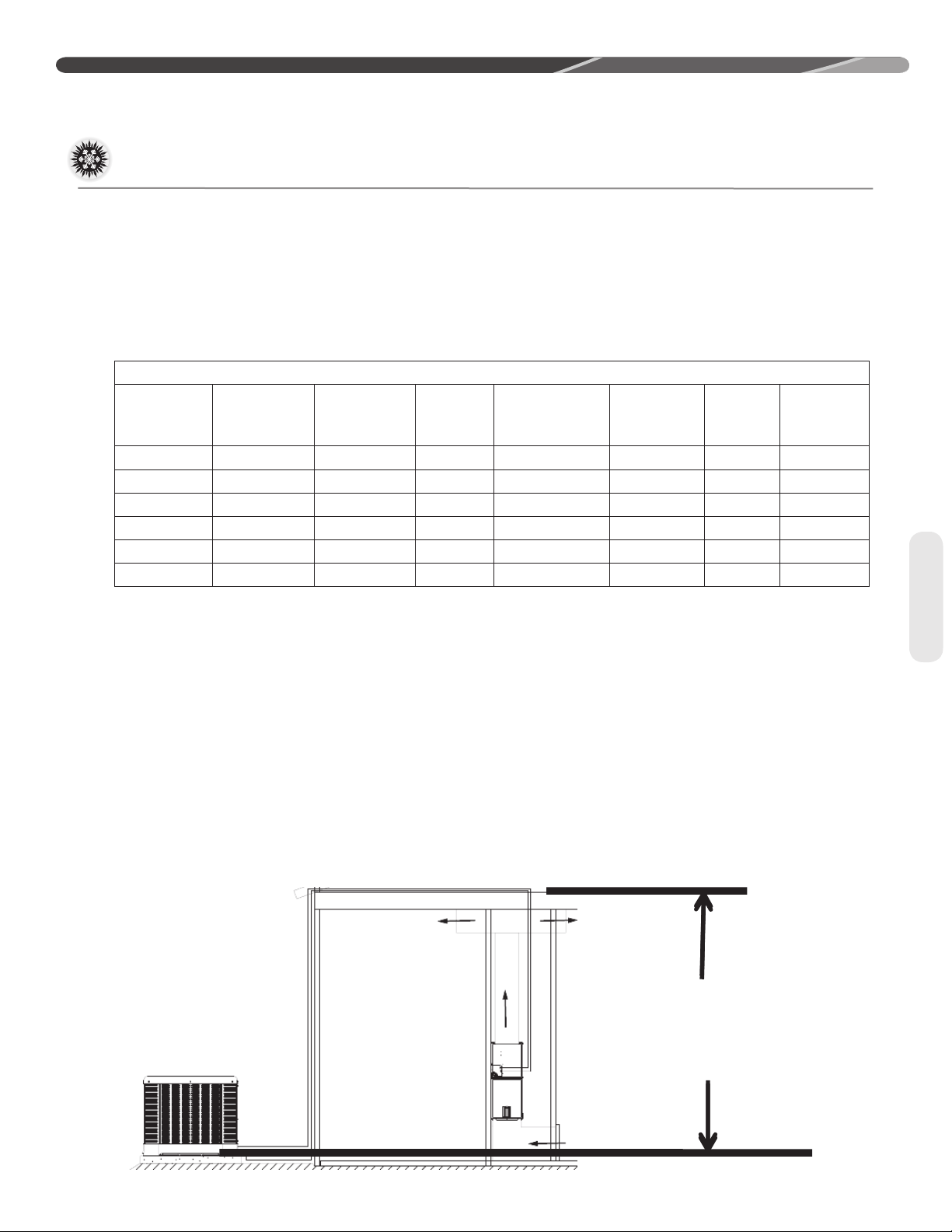
OUTDOOR UNIT LEVEL OR NEAR LEVEL TO INDOOR SECTION LINE SET
REFERENCE TABLE 2 FOR
MAXIMUM LENGTH LIMITATIONS
IDEALLY, LINE SET SLOPES AWAY
FROM OUTDOOR. VERIFY
SUB-COOLING PRIOR TO
THROTTLEING DEVICE, INSULATED
LIQUID LINE.
ST-A1219-01-01
15
Page 16

INSTALLATION
Interconnecting Tubing (cont�)
Tubing
For applications that are considered to have a long
line set with the outdoor unit and indoor unit on the
same level the following is required:
• TXV or EEV on the indoor unit
• Start components may be required depending
upon quality of voltage
• Crankcase heater
• Insulated liquid and suction line
OUTDOOR UNIT BELOW INDOOR SECTION LINE SET
INSULATE LIQUID
AND SUCTION
LINE
• Vapor line should slope toward the indoor unit
• Follow the proper line sizing, equivalent length,
charging requirements, and oil level adjustments
spelled out in this document and the outdoor
units I&O
• Verify at least 5°F sub-cooling at the ID unit prior
to throttling device
INVERT TRAP
EVEN WITH TOP
OF THE COIL
REFERENCE TABLE 2 FOR
MAXIMUM LENGTH LIMITATIONS
For applications that are considered to have a long
line set with the outdoor unit below the indoor unit
the following is required:
• TXV or EEV at the IDunit
• Crankcase heater
• Start components may be required depending
upon quality of voltage
• Inverted vapor-line trap (Reference Figure 3)
• Insulated liquid and suction line
16
ST-A1219-02-01
Figure 4
• Follow the proper line sizing, equivalent length,
charging requirements, and oil level adjustments
spelled out in this document and the outdoor
units I&O
• Measure pressure at the liquid line service valve
and prior to expansion device� Verify that it is
not greater than 50 PSI
• For elevations greater that 25’ can expect a
lower sub-cooling
Page 17

Interconnecting Tubing (cont�)
p
g
Outdoor Unit Above Indoor Unit
INSTALLATION
Verify sub-cooling prior
to throlin
device
Insulated liquid and
sucon line
TXV or EEV at indoor
eva
Figure 5
Reference Table 2
for elevaon
limitaons
Tubing
orator
For applications that are considered to have a long
line set with the outdoor unit above the indoor unit
the following is required:
• TXV at the indoor unit
• Crankcase heater
• Start components maybe required depending
upon quality of voltage
• Insulated liquid and suction line
• Follow the proper line sizing, equivalent length,
charging requirements, and oil level adjustments
spelled out in this document and the outdoor
units I&O
• Verify at least 5°F sub-cooling at the ID unit prior
to throttling device
17
Page 18

N/R N/R N/R N/R N/R N/R N/R N/R
1/4 [6.35] 25 [7.62] N/R N/R N/R N/R N/R N/R N/R N/R N/R N/R N/R
1/4 [6.35] N/R N/R N/R N/R N/R N/R N/R N/R N/R N/R N/R N/R
Grey=Thisapplicationisacceptable,butthelonglineguidelinesmustbefollowed.ReferenceLongLineSetsectionintheI&O
Liquid Line Size
Liquid Line Size
INSTALLATION
Interconnecting Tubing
NOTES:
N/R = Application not recommended.
RP1360 3/8" [9.53]
RP1348 3/8" [9.53]
RP1336
3/8" [9.53]
RP1324 3/8" [9.53]
R-410A System
Capacity Model
Size (Inch I.D.)
Connection
[mm]
Tubing
7/16 [11.12] 25 [7.62] 50 [15.24] 60 [18.29] 55 [16.76] 50 [15.24] 45 [13.72] 40 [12.19] 40 [12.19] 35 [10.67] 30 [9.14] 25 [7.62] 20 [6.1]
1/2 [12.71] 25 [7.62] 50 [15.24] 65 [19.81] 65 [19.81] 60 [18.29] 60 [18.29] 60 [18.29] 55 [16.76] 55 [16.76] 50 [15.24] 50 [15.24] 50 [15.24]
3/8 [9.53] 25 [7.62] 50 [15.24] 40 [12.19] 30 [9.14] 20 [6.1] 10 [3.05] N/R N/R N/R N/R N/R N/R
5/16 [7.94] 25 [7.62] 10 [3.05] N/R N/R N/R N/R N/R N/R N/R N/R N/R N/R
1/2 [12.71] 25 [7.62] 50 [15.24] 75 [22.86] 70 [21.34] 70 [21.34] 70 [21.34] 65 [19.81] 65 [19.81] 65 [19.81] 65 [19.81] 60 [18.29] 60 [18.29]
1/4 [6.35] N/R N/R N/R N/R N/R N/R N/R N/R N/R N/R N/R N/R
7/16 [11.12] 25 [7.62] 50 [15.24] 70 [21.34] 65 [19.81] 60 [18.29] 60 [18.29] 55 [16.76] 50 [15.24] 50 [15.24] 45 [13.72] 45 [13.72] 40 [12.19]
5/16 [7.94] 25 [7.62] 35 [10.67] 10 [3.05] N/R N/R N/R N/R N/R N/R N/R N/R N/R
3/8 [9.53] 25 [7.62] 50 [15.24] 55 [16.76] 45 [13.72] 40 [12.19] 30 [9.14] 25 [7.62] 15 [4.57] 10 [3.05] N/R N/R N/R
7/16 [11.12] 25 [7.62] 50 [15.24] 75 [22.86] 85 [25.91] 85 [25.91] 85 [25.91] 80 [24.38] 80 [24.38] 80 [24.38] 75 [22.86] 75 [22.86] 70 [21.34]
1/2 [12.71] 25 [7.62] 50 [15.24] 75 [22.86] 90 [27.43] 90 [27.43] 90 [27.43] 90 [27.43] 85 [25.91] 85 [25.91] 85 [25.91] 85 [25.91] 85 [25.91]
3/8 [9.53] 25 [7.62] 50 [15.24] 75 [22.86] 75 [22.86] 70 [21.34] 70 [21.34] 65 [19.81] 60 [18.29] 55 [16.76] 50 [15.24] 45 [13.72] 40 [12.19]
5/16 [7.94] 25 [7.62] 50 [15.24] 55 [16.76] 45 [13.72] 30 [9.14] 20 [6.1] N/R N/R N/R N/R N/R N/R
7/16 [11.12] 25 [7.62] 50 [15.24] 75 [22.86] 100 [30.48] 100 [30.48] 100 [30.48] 100 [30.48] 100 [30.48] 100 [30.48] 95 [28.96] 95 [28.96] 95 [28.96]
1/2 [12.71] 25 [7.62] 50 [15.24] 75 [22.86] 100 [30.48] 100 [30.48] 100 [30.48] 100 [30.48] 100 [30.48] 100 [30.48] 100 [30.48] 100 [30.48] 100 [30.48]
3/8 [9.53] 25 [7.62] 50 [15.24] 75 [22.86] 95 [28.96] 95 [28.96] 95 [28.96] 90 [27.43] 90 [27.43] 85 [25.91] 85 [25.91] 80 [24.38] 80 [24.38]
5/16 [7.94] 25 [7.62] 50 [15.24] 75 [22.86] 80 [24.38] 75 [22.86] 70 [21.34] 60 [18.29] 55 [16.76] 50 [15.24] 45 [13.72] 35 [10.67] 30 [9.14]
(Inch O.D.)
1/4 [6.35] 25 [7.62] 50 [15.24] 30 [9.14] 10 [3.05]
[mm]
25 [7.62] 50 [15.24] 75 [22.86] 100 [30.48] 125 [45.72] 150 [45.72] 175 [53.34] 200 [60.96] 225 [68.58] 250 [76.20] 275 [83.82] 300 [91.44]
Maximum Vertical Separation - Feet [m]
Total Equivalent Length - Feet [m]
Elevation (Above or Below) Indoor Coil
Liquid Line Selection Chart
18
Page 19

1/4 [6.35] 25 [7.62] 50 [15.24] 60 [18.29] 50 [15.24] 35 [10.67] 20 [6.1] N/R N/R N/R N/R N/R N/R
1/4 [6.35] 25 [7.62] 50 [15.24] 30 [9.14] 10 [3.05] N/R N/R N/R N/R N/R N/R N/R N/R
1/4 [6.35] 25 [7.62] 30 [9.14] N/R N/R N/R N/R N/R N/R N/R N/R N/R N/R
1/4 [6.35] 25 [7.62] N/R N/R N/R N/R N/R N/R N/R N/R N/R N/R N/R
1/4 [6.35] 5 [1.52] N/R N/R N/R N/R N/R N/R N/R N/R N/R N/R N/R
N/R N/R N/R N/R N/R N/R N/R N/R N/R N/R N/R N/R
1/4 [6.35] N/R N/R N/R N/R N/R N/R N/R N/R N/R N/R N/R N/R
Grey=Thisapplicationisacceptable,butthelonglineguidelinesmustbefollowed.ReferenceLongLineSetsectionintheI&O
R-410A System
Liquid Line Size
Liquid Line Size
INSTALLATION
Interconnecting Tubing
NOTES:
N/R = Application not recommended.
RP1460
3/8" [9.53]
RP1448
3/8" [9.53]
RP1442
3/8" [9.53]
RP1436
3/8" [9.53]
RP1430
3/8" [9.53]
RP1424
3/8" [9.53]
RP1418
3/8" [9.53]
Capacity Model
Size (Inch I.D.)
Connection
[mm]
7/16 [11.12] 25 [7.62] 50 [15.24] 60 [18.29] 55 [16.76] 50 [15.24] 45 [13.72] 40 [12.19] 40 [12.19] 35 [10.67] 30 [9.14] 25 [7.62] 20 [6.1]
1/2 [12.71] 25 [7.62] 50 [15.24] 65 [19.81] 65 [19.81] 60 [18.29] 60 [18.29] 60 [18.29] 55 [16.76] 55 [16.76] 50 [15.24] 50 [15.24] 50 [15.24]
3/8 [9.53] 25 [7.62] 50 [15.24] 40 [12.19] 30 [9.14] 20 [6.1] 10 [3.05] N/R N/R N/R N/R N/R N/R
5/16 [7.94] 25 [7.62] 10 [3.05] N/R N/R N/R N/R N/R N/R N/R N/R N/R N/R
7/16 [11.12] 25 [7.62] 50 [15.24] 70 [21.34] 65 [19.81] 60 [18.29] 60 [18.29] 55 [16.76] 50 [15.24] 50 [15.24] 45 [13.72] 45 [13.72] 40 [12.19]
1/2 [12.71] 25 [7.62] 50 [15.24] 75 [22.86] 70 [21.34] 70 [21.34] 70 [21.34] 65 [19.81] 65 [19.81] 65 [19.81] 65 [19.81] 60 [18.29] 60 [18.29]
3/8 [9.53] 25 [7.62] 50 [15.24] 55 [16.76] 45 [13.72] 40 [12.19] 30 [9.14] 25 [7.62] 15 [4.57] 10 [3.05] N/R N/R N/R
5/16 [7.94] 25 [7.62] 35 [10.67] 10 [3.05] N/R N/R N/R N/R N/R N/R N/R N/R N/R
1/4 [6.35]
7/16 [11.12] 25 [7.62] 50 [15.24] 70 [21.34] 65 [19.81] 65 [19.81] 60 [18.29] 60 [18.29] 55 [16.76] 55 [16.76] 50 [15.24] 50 [15.24] 45 [13.72]
1/2 [12.71] 25 [7.62] 50 [15.24] 70 [21.34] 70 [21.34] 70 [21.34] 70 [21.34] 65 [19.81] 65 [19.81] 65 [19.81] 65 [19.81] 60 [18.29] 60 [18.29]
3/8 [9.53] 25 [7.62] 50 [15.24] 60 [18.29] 50 [15.24] 45 [13.72] 40 [12.19] 35 [10.67] 30 [9.14] 20 [6.1] 15 [4.57] 10 [3.05] N/R
5/16 [7.94] 25 [7.62] 40 [12.19] 25 [7.62] 5 [1.52] N/R N/R N/R N/R N/R N/R N/R N/R
7/16 [11.12] 25 [7.62] 50 [15.24] 75 [22.86] 85 [25.91] 85 [25.91] 85 [25.91] 80 [24.38] 80 [24.38] 80 [24.38] 75 [22.86] 75 [22.86] 70 [21.34]
1/2 [12.71] 25 [7.62] 50 [15.24] 75 [22.86] 90 [27.43] 90 [27.43] 90 [27.43] 90 [27.43] 85 [25.91] 85 [25.91] 85 [25.91] 85 [25.91] 85 [25.91]
3/8 [9.53] 25 [7.62] 50 [15.24] 75 [22.86] 75 [22.86] 70 [21.34] 70 [21.34] 65 [19.81] 60 [18.29] 55 [16.76] 50 [15.24] 45 [13.72] 40 [12.19]
5/16 [7.94] 25 [7.62] 50 [15.24] 55 [16.76] 45 [13.72] 30 [9.14] 20 [6.1] N/R N/R N/R N/R N/R N/R
7/16 [11.12] 25 [7.62] 50 [15.24] 75 [22.86] 95 [28.96] 95 [28.96] 90 [27.43] 90 [27.43] 90 [27.43] 90 [27.43] 85 [25.91] 85 [25.91] 85 [25.91]
1/2 [12.71] 25 [7.62] 50 [15.24] 75 [22.86] 95 [28.96] 95 [28.96] 95 [28.96] 95 [28.96] 95 [28.96] 95 [28.96] 95 [28.96] 95 [28.96] 90 [27.43]
3/8 [9.53] 25 [7.62] 50 [15.24] 75 [22.86] 90 [27.43] 85 [25.91] 80 [24.38] 80 [24.38] 75 [22.86] 75 [22.86] 70 [21.34] 65 [19.81] 65 [19.81]
5/16 [7.94] 25 [7.62] 50 [15.24] 75 [22.86] 65 [19.81] 55 [16.76] 50 [15.24] 40 [12.19] 30 [9.14] 25 [7.62] 15 [4.57] 5 [1.52] N/R
7/16 [11.12] 25 [7.62] 50 [15.24] 75 [22.86] 100 [30.48] 100 [30.48] 100 [30.48] 100 [30.48] 100 [30.48] 100 [30.48] 95 [28.96] 95 [28.96] 95 [28.96]
1/2 [12.71] 25 [7.62] 50 [15.24] 75 [22.86] 100 [30.48] 100 [30.48] 100 [30.48] 100 [30.48] 100 [30.48] 100 [30.48] 100 [30.48] 100 [30.48] 100 [30.48]
3/8 [9.53] 25 [7.62] 50 [15.24] 75 [22.86] 95 [28.96] 95 [28.96] 95 [28.96] 90 [27.43] 90 [27.43] 85 [25.91] 85 [25.91] 80 [24.38] 80 [24.38]
5/16 [7.94] 25 [7.62] 50 [15.24] 75 [22.86] 80 [24.38] 75 [22.86] 70 [21.34] 60 [18.29] 55 [16.76] 50 [15.24] 45 [13.72] 35 [10.67] 30 [9.14]
7/16 [11.12] 25 [7.62] 50 [15.24] 75 [22.86] 100 [30.48] 105 [32] 100 [30.48] 100 [30.48] 100 [30.48] 100 [30.48] 100 [30.48] 100 [30.48] 100 [30.48]
1/2 [12.71] 25 [7.62] 50 [15.24] 75 [22.86] 100 [30.48] 105 [32] 105 [32] 105 [32] 105 [32] 105 [32] 105 [32] 100 [30.48] 100 [30.48]
3/8 [9.53] 25 [7.62] 50 [15.24] 75 [22.86] 100 [30.48] 100 [30.48] 100 [30.48] 95 [28.96] 95 [28.96] 95 [28.96] 90 [27.43] 90 [27.43] 90 [27.43]
5/16 [7.94] 25 [7.62] 50 [15.24] 75 [22.86] 90 [27.43] 85 [25.91] 85 [25.91] 80 [24.38] 75 [22.86] 70 [21.34] 70 [21.34] 65 [19.81] 60 [18.29]
(Inch O.D.)
[mm]
25 [7.62] 50 [15.24] 75 [22.86] 100 [30.48] 125 [45.72] 150 [45.72] 175 [53.34] 200 [60.96] 225 [68.58] 250 [76.20] 275 [83.82] 300 [91.44]
Maximum Vertical Separation - Feet [m]
Total Equivalent Length - Feet [m]
Tubing
Elevation (Above or Below) Indoor Coil
Liquid Line Selection Chart
19
Page 20

N/R N/R N/R N/R N/R N/R
1/4 [6.35] 25 [7.62] 50 [15.24] 30 [9.14] N/R N/R N/R N/R N/R N/R N/R N/R N/R
N/R N/R N/R N/R N/R N/R N/R N/R N/R N/R
1/4 [6.35] 25 [7.62] N/R N/R N/R N/R N/R N/R N/R N/R N/R N/R N/R
1/4 [6.35] 25 [7.62] N/R N/R N/R N/R N/R N/R N/R N/R N/R N/R N/R
1/4 [6.35] N/R N/R N/R N/R N/R N/R N/R N/R N/R N/R N/R N/R
Grey=Thisapplicationisacceptable,butthelonglineguidelinesmustbefollowed.ReferenceLongLineSetsectionintheI&O.
Liquid Line Size
Liquid Line Size
INSTALLATION
Interconnecting Tubing
NOTES:
N/R = Application not recommended.
3/8" [9.53]
3/8" [9.53]
3/8" [9.53]
3/8" [9.53]
3/8" [9.53]
3/8" [9.53]
3/8" [9.53]
R-410A System
Capacity Model
Size (Inch I.D.)
Connection
[mm]
7/16 [11.12] 25 [7.62] 50 [15.24] 55 [16.76] 50 [15.24] 50 [15.24] 45 [13.72] 40 [12.19] 35 [10.67] 30 [9.14] 25 [7.62] 25 [7.62] 20 [6.1]
1/2 [12.71] 25 [7.62] 50 [15.24] 60 [18.29] 60 [18.29] 60 [18.29] 55 [16.76] 55 [16.76] 50 [15.24] 50 [15.24] 50 [15.24] 45 [13.72] 45 [13.72]
3/8 [9.53] 25 [7.62] 50 [15.24] 40 [12.19] 30 [9.14] 20 [6.1] 10 [3.05] N/R N/R N/R N/R N/R N/R
5/16 [7.94] 25 [7.62] 10 [3.05] N/R N/R N/R N/R N/R N/R N/R N/R N/R N/R
7/16 [11.12] 25 [7.62] 50 [15.24] 75 [22.86] 80 [24.38] 75 [22.86] 75 [22.86] 70 [21.34] 70 [21.34] 65 [19.81] 60 [18.29] 60 [18.29] 55 [16.76]
1/2 [12.71] 25 [7.62] 50 [15.24] 75 [22.86] 85 [25.91] 85 [25.91] 80 [24.38] 80 [24.38] 80 [24.38] 80 [24.38] 75 [22.86] 75 [22.86] 75 [22.86]
3/8 [9.53] 25 [7.62] 50 [15.24] 70 [21.34] 65 [19.81] 55 [16.76] 50 [15.24] 40 [12.19] 35 [10.67] 30 [9.14] 20 [6.1] 15 [4.57] 10 [3.05]
5/16 [7.94] 25 [7.62] 50 [15.24] 30 [9.14] 10 [3.05] N/R N/R N/R N/R N/R N/R N/R N/R
1/2 [12.71] 25 [7.62] 50 [15.24] 75 [22.86] 90 [27.43] 90 [27.43] 90 [27.43] 90 [27.43] 85 [25.91] 85 [25.91] 85 [25.91] 85 [25.91] 80 [24.38]
1/4 [6.35] 10 [3.05] N/R N/R N/R N/R N/R N/R N/R N/R N/R N/R N/R
7/16 [11.12] 25 [7.62] 50 [15.24] 75 [22.86] 85 [25.91] 85 [25.91] 80 [24.38] 80 [24.38] 75 [22.86] 75 [22.86] 70 [21.34] 70 [21.34] 65 [19.81]
5/16 [7.94] 25 [7.62] 50 [15.24] 45 [13.72] 30 [9.14] 10 [3.05] N/R N/R N/R N/R N/R N/R N/R
3/8 [9.53] 25 [7.62] 50 [15.24] 75 [22.86] 75 [22.86] 65 [19.81] 60 [18.29] 55 [16.76] 50 [15.24] 45 [13.72] 40 [12.19] 30 [9.14] 25 [7.62]
7/16 [11.12] 25 [7.62] 50 [15.24] 75 [22.86] 95 [28.96] 95 [28.96] 90 [27.43] 90 [27.43] 85 [25.91] 85 [25.91] 85 [25.91] 80 [24.38] 80 [24.38]
1/2 [12.71] 25 [7.62] 50 [15.24] 75 [22.86] 100 [30.48] 95 [28.96] 95 [28.96] 95 [28.96] 95 [28.96] 95 [28.96] 95 [28.96] 90 [27.43] 90 [27.43]
3/8 [9.53] 25 [7.62] 50 [15.24] 75 [22.86] 85 [25.91] 80 [24.38] 75 [22.86] 70 [21.34] 65 [19.81] 65 [19.81] 60 [18.29] 55 [16.76] 50 [15.24]
5/16 [7.94] 25 [7.62] 50 [15.24] 65 [19.81] 50 [15.24] 40 [12.19] 25 [7.62] 15 [4.57] N/R N/R N/R N/R N/R
7/16 [11.12] 25 [7.62] 50 [15.24] 75 [22.86] 90 [27.43] 90 [27.43] 90 [27.43] 85 [25.91] 85 [25.91] 85 [25.91] 85 [25.91] 80 [24.38] 80 [24.38]
1/2 [12.71] 25 [7.62] 50 [15.24] 75 [22.86] 95 [28.96] 95 [28.96] 90 [27.43] 90 [27.43] 90 [27.43] 90 [27.43] 90 [27.43] 90 [27.43] 90 [27.43]
3/8 [9.53] 25 [7.62] 50 [15.24] 75 [22.86] 85 [25.91] 80 [24.38] 80 [24.38] 75 [22.86] 70 [21.34] 70 [21.34] 65 [19.81] 65 [19.81] 60 [18.29]
5/16 [7.94] 25 [7.62] 50 [15.24] 70 [21.34] 60 [18.29] 55 [16.76] 45 [13.72] 35 [10.67] 30 [9.14] 20 [6.1] 10 [3.05] N/R N/R
1/4 [6.35] 25 [7.62] 30 [9.14]
7/16 [11.12] 25 [7.62] 50 [15.24] 75 [22.86] 100 [30.48] 100 [30.48] 95 [28.96] 95 [28.96] 95 [28.96] 95 [28.96] 95 [28.96] 95 [28.96] 90 [27.43]
1/2 [12.71] 25 [7.62] 50 [15.24] 75 [22.86] 100 [30.48] 100 [30.48] 100 [30.48] 100 [30.48] 100 [30.48] 100 [30.48] 100 [30.48] 95 [28.96] 95 [28.96]
3/8 [9.53] 25 [7.62] 50 [15.24] 75 [22.86] 95 [28.96] 90 [27.43] 90 [27.43] 90 [27.43] 85 [25.91] 85 [25.91] 80 [24.38] 80 [24.38] 75 [22.86]
5/16 [7.94] 25 [7.62] 50 [15.24] 75 [22.86] 80 [24.38] 70 [21.34] 65 [19.81] 60 [18.29] 50 [15.24] 45 [13.72] 40 [12.19] 35 [10.67] 25 [7.62]
7/16 [11.12] 25 [7.62] 50 [15.24] 75 [22.86] 100 [30.48] 105 [32] 100 [30.48] 100 [30.48] 100 [30.48] 100 [30.48] 100 [30.48] 100 [30.48] 100 [30.48]
1/2 [12.71] 25 [7.62] 50 [15.24] 75 [22.86] 100 [30.48] 105 [32] 105 [32] 105 [32] 105 [32] 105 [32] 105 [32] 100 [30.48] 100 [30.48]
3/8 [9.53] 25 [7.62] 50 [15.24] 75 [22.86] 100 [30.48] 100 [30.48] 100 [30.48] 95 [28.96] 95 [28.96] 95 [28.96] 90 [27.43] 90 [27.43] 90 [27.43]
5/16 [7.94] 25 [7.62] 50 [15.24] 75 [22.86] 90 [27.43] 85 [25.91] 85 [25.91] 80 [24.38] 75 [22.86] 70 [21.34] 70 [21.34] 65 [19.81] 60 [18.29]
(Inch O.D.)
1/4 [6.35] 25 [7.62] 50 [15.24] 60 [18.29] 50 [15.24] 35 [10.67] 20 [6.1]
[mm]
25 [7.62] 50 [15.24] 75 [22.86] 100 [30.48] 125 [45.72] 150 [45.72] 175 [53.34] 200 [60.96] 225 [68.58] 250 [76.20] 275 [83.82] 300 [91.44]
Maximum Vertical Separation - Feet [m]
Total Equivalent Length - Feet [m]
Elevation Above or Below Indoor Coil
Liquid Line Size
20
Page 21

5/8 [15.88] 0.99 0.99 0.98 0.98 0.97 0.97 0.96 0.96 0.96 0.95 0.95 0.94
5/8 [15.88] 0.97 0.95 0.94 0.92 0.89 0.88 0.86 0.86 0.84 N/R N/R N/R
5/8 [15.88] 0.98 0.94 0.92 0.9 0.88 0.85 N/R N/R N/R N/R N/R N/R
NOTES:
INSTALLATION
Vapor Line Size
N/R = Application not recommended.
RP1360 3/8" [9.53]
RP1348 3/8" [9.53]
RP1336
3/8" [9.53]
RP1324 3/8" [9.53]
R-410A System
Capacity Model
Liquid Line Size
Size (Inch I.D.)
Connection
[mm]
Interconnecting Tubing (cont.)
1-1/8 [28.58] N/R N/R N/R N/R N/R N/R N/R N/R N/R N/R N/R N/R
1 [25.4] 1.01 1.00 1.01 1.01 1.00 1.00 N/R N/R N/R N/R N/R N/R
7/8 [22.23] 1.00 1.00 1.00 0.99 0.99 0.98 N/R N/R N/R N/R N/R N/R
3/4 [19.05] 1.00 0.99 0.98 0.96 0.95 0.94 N/R N/R N/R N/R N/R N/R
1-1/8 [28.58] N/R N/R N/R N/R N/R N/R N/R N/R N/R N/R N/R N/R
1 [25.4] 1.00 1.00 1.00 0.99 0.99 1.00 0.99 1.00 0.99 N/R N/R N/R
7/8 [22.23] 1.00 0.99 0.99 0.99 0.98 0.98 0.98 0.97 0.97 N/R N/R N/R
3/4 [19.05] 0.99 0.99 0.98 0.97 0.96 0.96 0.95 0.94 0.93 N/R N/R N/R
1-1/8 [28.58] N/R N/R N/R N/R N/R N/R N/R N/R N/R N/R N/R N/R
1 [25.4] 1.01 1.00 1.00 1.00 1.00 1.00 1.00 1.00 1.00 1.00 1.00 1.00
7/8 [22.23] 1.00 1.00 1.00 1.00 0.99 0.99 0.99 0.99 0.99 0.98 0.98 0.98
3/4 [19.05] 1.00 0.99 0.98 0.98 0.97 0.97 0.97 0.96 0.96 0.95 0.94 0.94
5/8 [15.88] 0.99 0.97 0.95 0.93 0.92 0.91 0.9 0.9 0.9 0.87 0.87 0.86
1-1/8 [28.58] N/R N/R N/R N/R N/R N/R N/R N/R N/R N/R N/R N/R
1 [25.4] N/R N/R N/R N/R N/R N/R N/R N/R N/R N/R N/R N/R
7/8 [22.23] 1.00 1.00 1.00 1.00 1.00 1.00 1.00 1.01 1.01 1.01 1.01 1.01
3/4 [19.05] 1.00 1.00 1.00 1.00 1.00 1.00 1.00 1.00 0.99 0.99 0.99 0.99
(Inch O.D.)
[mm]
25 [7.62] 50 [15.24] 75 [22.86] 100 [30.48] 125 [45.72] 150 [45.72] 175 [53.34] 200 [60.96] 225 [68.58] 250 [76.20] 275 [83.82] 300 [91.44]
Total Equivalent Length - Feet [m]
Capacity Multiplier Table
Suction Line Selection Chart
21
Page 22

5/8 [15.88] 0.99 0.99 0.98 0.98 0.97 0.97 0.96 0.96 0.96 0.95 0.95 0.94
5/8 [15.88] 0.99 0.98 0.97 0.96 0.96 0.94 0.93 0.93 0.93 0.91 0.91 0.9
5/8 [15.88] 0.99 0.97 0.95 0.93 0.92 0.91 0.9 0.9 0.9 0.87 0.87 0.86
5/8 [15.88] 0.97 0.95 0.94 0.92 0.89 0.88 0.86 0.86 0.84 N/R N/R N/R
5/8 [15.88] 0.98 0.94 0.92 0.9 0.88 0.85 N/R N/R N/R N/R N/R N/R
NOTES:
INSTALLATION
Interconnecting Tubing (cont.)
Liquid Line Size
Vapor Line Size
N/R = Application not recommended.
3/8" [9.53]
3/8" [9.53]
3/8" [9.53]
3/8" [9.53]
3/8" [9.53]
3/8" [9.53]
3/8" [9.53]
R-410A System
Capacity Model
Size (Inch I.D.)
Connection
[mm]
1-1/8 [28.58] N/R N/R N/R N/R N/R N/R N/R N/R N/R N/R N/R N/R
1 [25.4] 1.01 1.00 1.01 1.01 1.00 1.00 N/R N/R N/R N/R N/R N/R
7/8 [22.23] 1.00 1.00 1.00 0.99 0.99 0.98 N/R N/R N/R N/R N/R N/R
3/4 [19.05] 1.00 0.99 0.98 0.96 0.95 0.94 N/R N/R N/R N/R N/R N/R
1-1/8 [28.58] N/R N/R N/R N/R N/R N/R N/R N/R N/R N/R N/R N/R
1 [25.4] 1.00 1.00 1.00 0.99 0.99 1.00 0.99 1.00 0.99 N/R N/R N/R
7/8 [22.23] 1.00 0.99 0.99 0.99 0.98 0.98 0.98 0.97 0.97 N/R N/R N/R
3/4 [19.05] 0.99 0.99 0.98 0.97 0.96 0.96 0.95 0.94 0.93 N/R N/R N/R
1-1/8 [28.58] 1.01 1.01 1.00 1.00 1.00 1.00 1.00 1.00 1.00 1.01 1.01 N/R
1 [25.4] 1.01 1.00 1.00 1.00 1.00 1.00 1.00 1.00 0.99 0.99 1.00 N/R
7/8 [22.23] 1.00 1.00 1.00 0.99 1.00 0.99 0.99 0.99 0.98 0.98 0.98 N/R
3/4 [19.05] 0.99 0.98 0.98 0.98 0.97 0.97 0.96 0.96 0.95 0.95 0.94 N/R
5/8 [15.88] 0.98 0.97 0.95 0.94 0.92 0.91 0.89 0.88 0.87 0.86 0.85 N/R
1-1/8 [28.58] N/R N/R N/R N/R N/R N/R N/R N/R N/R N/R N/R N/R
1 [25.4] 1.01 1.00 1.00 1.00 1.00 1.00 1.00 1.00 1.00 1.00 1.00 1.00
7/8 [22.23] 1.00 1.00 1.00 1.00 0.99 0.99 0.99 0.99 0.99 0.98 0.98 0.98
3/4 [19.05] 1.00 0.99 0.98 0.98 0.97 0.97 0.97 0.96 0.96 0.95 0.94 0.94
1-1/8 [28.58] N/R N/R N/R N/R N/R N/R N/R N/R N/R N/R N/R N/R
1 [25.4] 1.00 1.01 1.01 1.01 1.01 1.01 1.01 1.01 1.01 1.01 1.01 1.00
7/8 [22.23] 1.00 1.01 1.01 1.00 1.00 1.01 1.01 1.00 1.00 1.00 1.00 0.99
3/4 [19.05] 1.00 1.00 1.00 0.99 0.98 0.98 0.98 0.98 0.98 0.97 0.96 0.96
1-1/8 [28.58] N/R N/R N/R N/R N/R N/R N/R N/R N/R N/R N/R N/R
1 [25.4] N/R N/R N/R N/R N/R N/R N/R N/R N/R N/R N/R N/R
7/8 [22.23] 1.00 1.00 1.00 1.00 1.00 1.00 1.00 1.01 1.01 1.01 1.01 1.01
3/4 [19.05] 1.00 1.00 1.00 1.00 1.00 1.00 1.00 1.00 0.99 0.99 0.99 0.99
1-1/8 [28.58] N/R N/R N/R N/R N/R N/R N/R N/R N/R N/R N/R N/R
1 [25.4] N/R N/R N/R N/R N/R N/R N/R N/R N/R N/R N/R N/R
7/8 [22.23] N/R N/R N/R N/R N/R N/R N/R N/R N/R N/R N/R N/R
3/4 [19.05] 1.00 1.00 1.00 1.00 1.00 1.00 1.00 1.00 1.00 1.00 1.00 1.00
5/8 [15.88] 1.00 0.99 0.99 0.99 0.99 0.98 0.98 0.98 0.97 0.97 0.97 0.97
(Inch O.D.)
[mm]
25 [7.62] 50 [15.24] 75 [22.86] 100 [30.48] 125 [45.72] 150 [45.72] 175 [53.34] 200 [60.96] 225 [68.58] 250 [76.20] 275 [83.82] 300 [91.44]
Total Equivalent Length - Feet [m]
Capacity Multiplier Table
Suction Line Selection Chart
22
Page 23

5/8 [15.88] 1.00 1.00 1.00 0.99 0.99 0.98 0.98 0.98 0.97 0.97 0.97 0.97
5/8 [15.88] 1.00 0.99 0.98 0.98 0.97 0.97 0.96 0.96 0.95 0.95 0.94 0.93
5/8 [15.88] 0.99 0.98 0.97 0.95 0.94 0.94 0.93 0.92 0.91 0.91 0.9 0.88
5/8 [15.88] 0.99 0.96 0.94 0.92 0.91 0.89 0.87 0.86 0.84 0.83 0.82 0.8
5/8 [15.88] 0.79 0.99 0.95 0.93 0.91 0.89 N/R N/R N/R N/R N/R N/R
Allcalculationsassumea3/8"liquidline
INSTALLATION
R-410A System
Vapor Line Size
NOTES:
N/R = Application not recommended.
3/4" [19.06]
3/4" [19.06]
3/4" [19.06]
3/4" [19.06]
3/4" [19.06]
3/4" [19.06]
3/4" [19.06]
Capacity Model
Connection Size
(Inch I.D.) [mm]
Vapor Line
Interconnecting Tubing (cont.)
1-1/8 [28.58] N/R N/R N/R N/R N/R N/R N/R N/R N/R N/R N/R N/R
1 [25.4] 1.00 1.02 1.01 1.01 1.01 1.01 N/R N/R N/R N/R N/R N/R
7/8 [22.23] 1.00 1.01 1.01 1.01 1.00 1.00 N/R N/R N/R N/R N/R N/R
3/4 [19.05] 0.9 1.01 1.00 0.99 0.97 0.96 N/R N/R N/R N/R N/R N/R
1-1/8 [28.58] N/R N/R N/R N/R N/R N/R N/R N/R N/R N/R N/R N/R
1 [25.4] N/R N/R N/R N/R N/R N/R N/R N/R N/R N/R N/R N/R
7/8 [22.23] 1.00 1.01 1.01 1.00 1.00 0.99 0.99 0.99 0.98 0.98 0.97 0.97
3/4 [19.05] 1.01 1.00 0.99 0.97 0.97 0.96 0.95 0.94 0.94 0.93 0.92 0.92
1-1/8 [28.58] 1.03 1.03 1.02 1.02 1.02 1.02 1.02 1.02 1.02 1.02 1.01 1.01
1 [25.4] 1.03 1.02 1.02 1.02 1.02 1.01 1.01 1.01 1.01 1.01 1.01 1.01
7/8 [22.23] 1.00 1.01 1.01 1.01 1.01 1.01 1.01 1.00 0.99 1.00 1.00 0.99
3/4 [19.05] 1.01 1.01 1.00 0.99 0.99 0.98 0.97 0.97 0.96 0.95 0.95 0.94
5/8 [15.88] 1.00 0.98 0.96 0.95 0.94 0.92 0.91 0.89 0.88 0.87 0.86 0.85
1-1/8 [28.58] N/R N/R N/R N/R N/R N/R N/R N/R N/R N/R N/R N/R
1 [25.4] 1.01 1.01 1.01 1.01 1.01 1.01 1.01 1.00 1.00 1.00 1.00 1.01
7/8 [22.23] 1.01 1.01 1.01 1.00 1.00 1.00 1.00 1.00 1.00 0.99 0.98 0.98
3/4 [19.05] 1.00 1.00 0.99 0.98 0.99 0.99 0.98 0.97 0.97 0.96 0.96 0.95
5/8 [15.88] 1.00 0.97 0.97 0.95 0.94 0.93 0.91 0.92 0.91 0.88 0.87 0.86
1-1/8 [28.58] N/R N/R N/R N/R N/R N/R N/R N/R N/R N/R N/R N/R
1 [25.4] 1.00 1.00 1.00 1.00 1.00 1.00 1.00 1.00 1.00 1.00 0.99 0.99
7/8 [22.23] 1.00 1.00 1.00 1.00 1.00 0.99 0.99 0.98 0.98 0.98 0.98 0.98
3/4 [19.05] 1.00 1.00 0.99 0.98 0.98 0.98 0.97 0.97 0.97 0.96 0.96 0.95
1-1/8 [28.58] N/R N/R N/R N/R N/R N/R N/R N/R N/R N/R N/R N/R
1 [25.4] N/R N/R N/R N/R N/R N/R N/R N/R N/R N/R N/R N/R
7/8 [22.23] 1.00 1.00 1.00 1.00 0.99 1.00 1.00 1.00 1.00 1.00 1.01 1.01
3/4 [19.05] 1.00 1.00 1.00 0.99 1.00 0.99 0.99 1.00 0.99 0.99 0.99 0.99
1-1/8 [28.58] N/R N/R N/R N/R N/R N/R N/R N/R N/R N/R N/R N/R
1 [25.4] N/R N/R N/R N/R N/R N/R N/R N/R N/R N/R N/R N/R
7/8 [22.23] N/R N/R N/R N/R N/R N/R N/R N/R N/R N/R N/R N/R
3/4 [19.05] 1.00 1.00 1.00 1.00 1.00 1.00 1.00 1.00 1.00 1.00 1.00 1.00
(Inch O.D.)
[mm]
25 [7.62] 50 [15.24] 75 [22.86] 100 [30.48] 125 [45.72] 150 [45.72] 175 [53.34] 200 [60.96] 225 [68.58] 250 [76.20] 275 [83.82] 300 [91.44]
Total Equivalent Length - Feet [m]
Capacity Multiplier Table
Vapor Line Selection Chart
23
Page 24

Tubing
INSTALLATION
Interconnecting Tubing (cont�)
Tubing Installation
Observe the following when installing correctly
sized type “L” refrigerant tubing between the
condensing unit and evaporator coil:
• Check the tables on page 12 for the correct
suction line size and liquid line size�
• If a portion of the liquid line passes through a
very hot area where liquid refrigerant can be
heated to form vapor, insulating the liquid line is
required�
• Use clean, dehydrated, sealed refrigeration-
grade tubing�
• Always keep tubing sealed until tubing is in place
and connections are to be made�
• A high-quality biflow filter drier is included
with all R-410A heat pump units and must be
installed in the liquid line upon unit installation�
• When replacing an R-22 system with an R-410A
system and the line set is not replaced, use a
flush kit available through aftermarket stores
such as Prostock�
• If tubing has been cut, make sure ends are
deburred while holding in a position to prevent
chips from falling into tubing� Burrs such as
those caused by tubing cutters can affect
performance dramatically, particularly on small
liquid line sizes�
• For best operation, keep tubing run as short as
possible with a minimum number of elbows or
bends�
• Locations where the tubing will be exposed to
mechanical damage should be avoided� If it is
necessary to use such locations, the copper
tubing should be housed to prevent damage�
24
Page 25

INSTALLATION
TEMPORARY
HANGER
PERMANENT
HANGER
ST-A1226-05-00
Interconnecting Tubing
• If tubing is to be run underground, it must be run
in a sealed watertight chase�
• Use care in routing tubing and do not kink or
twist� Use a good tubing bender on the vapor
line to prevent kinking�
• Route the tubing using temporary hangers; then
straighten the tubing and install permanent
hangers� Line must be adequately supported�
• If the vapor line comes in contact with inside
walls, ceiling, or flooring, the vibration of the
vapor line in the heating mode will result in noise
inside the structure�
(cont�)
• Be certain both refrigerant shutoff valves at the
outdoor unit are closed�
•
Remove the caps and Schrader cores from the
pressure ports to protect seals from heat damage�
Both the Schrader valves and the service valves
have seals that may be damaged by excessive heat�
Tubing
• Blow out the liquid and vapor lines with dry
nitrogen before connecting to the outdoor unit
and indoor coil� Any debris in the line set will end
up plugging the expansion device�
Tubing Connections
Indoor coils have only a holding charge of
dry nitrogen� Keep all tube ends sealed until
connections are to be made�
• Use type “L” copper refrigeration tubing. Braze
the connections with the following alloys:
– copper to copper, 5% silver minimum
– copper to steel or brass, 15% silver minimum
•
Clean the inside of the fittings and outside of the
tubing with a clean, dry cloth before soldering�
Clean out debris, chips, dirt, etc�, that enters tubing
or service valve connections�
•
Wrap valves with a wet rag or thermal barrier
compound before applying heat�
25
Page 26

INSTALLATION
ST-A1226-06-00
Tubing
Interconnecting Tubing
•
Braze the tubing between the outdoor unit and
indoor coil� Flow dry nitrogen into a pressure port
and through the tubing while brazing, but do not
allow pressure inside tubing which can result in
leaks� Once the system is full of nitrogen, the
nitrogen regulator should be turned off to avoid
pressuring the system�
(cont�)
Leak Testing
Indoor coils have only a holding charge of dry
nitrogen� Keep all tube ends sealed until
connections are to be made�
WARNING: Do not use oxygen
to purge lines or pressurize system for leak test�
Oxygen reacts violently with oil, which can cause
an explosion resulting in severe personal injury or
death�
ST-A1226-07-00
• A
fter brazing, use an appropriate heatsink material
to cool the joint�
• Reinstall the Schrader cores into both pressure
ports�
• Do not allow the vapor line and liquid line to
be in contact with each other� This causes an
undesirable heat transfer resulting in capacity
loss and increased power consumption�
•
Pressurize line set and coil through service fittings
with dry nitrogen to 150 PSIG maximum� Close
nitrogen tank valve, let system sit for at least
15 minutes, and check to see if the pressure has
dropped� If the pressure has dropped, check for
leaks at the line set braze joints with soap bubbles
and repair leak as necessary� Repeat pressure
test� If line set and coil hold pressure, proceed
with line set and coil evacuation (see page 21)�
• The vapor line must be insulated for its entire
length to prevent dripping (sweating) and prevent
performance losses� Closed-cell foam insulation
such as Armaflex and Rubatex® are satisfactory
insulations for this purpose. Use 1/2" [12.7 mm]
minimum insulation thickness� Additional
insulation may be required for long runs�
26
Page 27

Control Wiring
WIRING
WARNING: Turn o electric power
at the fuse box or service panel before making
any electrical connections� Also, the ground
connection must be completed before making line
voltage connections� Failure to do so can result in
electrical shock, severe personal injury, or death�
Control Wiring
Running low-voltage wires in conduit with line
voltage power wires is not recommended� Lowvoltage wiring may be run through the insulated
plastic bushing provided in the 7/8" [19 mm]
hole in the base panel, up to and attached to
the pigtails from the bottom of the control box�
Conduit can be run to the base panel if desired by
removing the insulated bushing�
A thermostat and a 24-volt, 40 VA minimum
transformer are required for the control circuit
of the system� The furnace or the air handler
transformer may be used if sufficient� See the
wiring diagram for reference� Use “Wire Size” table
on this page to size the 24-volt control wiring�
Do not use phone cord to connect indoor and
outdoor units and thermostat� This could damage
the controls and may not be adequately sized for
the control’s electrical load�
FIELD WIRE SIZE FOR 24-VOLT THERMOSTAT CIRCUITS
SOLID COPPER WIRE –AWG.
3.0 18 16 14 12 10 10 10
2.5 18 16 14 12 10 10 10
2.0 18 16 14 12 10 10 10
20 50 100 150 200 250 300
[6] [15] [30] [46] [51] [76] [91]
Length of Run – Feet [m] (1)
(1) Wire length equals twice the run distance�
NOTICE: Do not use control wiring smaller than No� 18
AWG between thermostat and outdoor unit�
Typical Noncommunicating
Thermostat Wiring Diagrams
The following figures show the typical wiring
diagrams for RH1T; RHIV air handlers and 1-stage
heat pump and dual fuel applications with a gas
furnace and 1-stage heat pump� Cooling and
heat pump airflows may need to be adjusted
for homeowner comfort once the system is
operational�
WIRE COLOR CODE
BK – BLACK GY – GRAY W – WHITE
BR – BROWN O – ORANGE Y – YELLOW
BL – BLUE PR – PURPLE
G – GREEN R – RED
Wiring
TYPICAL
CONTROL WIRING FOR AIR HANDLER
*If maximum outlet temperature rise is
desired, it is recommended that W1 and
W2 be jumpered together.
Air Handler
WH/BL
W2
GR/BK
G
*Not present on all
air-handler models.
*
WIRING INFORMATION
Line Voltage
1
Y
WH/BK
W1
BL
*
B
GR/YL
*
ODD
BR
C
R
YL/BL
*
2
Y
Field Installed
-
-
Factory Standard
YL
RD
OPTIONAL
- 1 STAGE HEAT
Heat Pump Thermostat
Optional Field Installed Jumper (see note 1)
C
R
E
W2
G
B
Y
Heat Pump
Outdoor Unit
YL
Y
BL
B
BR
C
RD
R
PR
D
NOTES:
1. Jumper “E” to “W2” on
thermostat to transfer
control of supplemental
heat to 1st stage when
the emergency heat
switch is on.
2. This wire turns on electric heat strip during
defrost, omit for most
economical operation.
WIRE COLOR CODE
BK = BLACK
BL = BLUE
BR = BROWN
GR = GREEN
PR = PURPLE
RD = RED
WH = WHITE
YL = YELLOW
27
Page 28

WIRING
NOTES:
(1) FOR PROGRAMMING THERMOSTAT IN DUAL-FUEL APPLICATION, SEE
THERMOSTAT INSTALLATION INFORMATION.
(2) FOR REMOTE SENSOR INSTALLATION, SEE THERMOSTAT INSTALLATION INFORMATION.
(3) OPTIONAL PLENUM SENSOR.
(4) EMERGENCY HEAT (E) CONNECTION MAY NOT BE ALLOWED BY LOCAL CODES.
R
C
W2
W/E
Y
G
B
+
S
–
R
C
D
Y
B
R
C
W
Y
G
PS
(3)
Outdoor
Sensor
(2)
12 FT.
(3.7 M )
R
BR
Y
Y/BL
PR
BL
Heat Pump
Outdoor Unit
Typical
One-Stage
Thermostat
Furnace
Control
(4)
Control Wiring (cont�)
Wiring
TYPICAL 1-STAGE DUAL FUEL THERMOSTAT AND
DUAL-FUEL APPLICATION
Field wiring must comply with the National Electric
Code (C�E�C� in Canada) and any applicable local
code�
Power Wiring
It is important that proper electrical power from
a commercial utility is available at the heat pump
contactor� Voltage ranges for operation are shown
below�
VOLTAGE RANGES (60 HZ)
Nameplate Voltage Load Design Conditions for Compressors
208/230 (1 Phase) 187 - 253
208/230 (3 Phase) 187 - 253
460 414 - 506
575 517 633
Operating Voltage Range at Maximum
Copeland
Power wiring must be run in a rain-tight conduit�
Conduit must be run through the connector panel
below the access cover (see page 6) and attached
to the bottom of the control box�
ST-A1226-09
Connect power wiring to line-voltage lugs located
in the outdoor heat pump unit electrical box� (See
wiring diagram attached to unit access panel�)
Check all electrical connections, including
factory wiring within the unit and make sure all
connections are tight�
DO NOT connect aluminum field wire to the
Comfort Control2 terminals�
Grounding
WARNING: The unit must be
permanently grounded� Failure to do so can cause
electrical shock resulting in severe personal injury
or death�
Install a branch circuit disconnect within sight
of the unit and of adequate size to handle the
starting current (see “Electrical Data” on page 5�)
28
ST-A1226-09
A grounding lug is provided near the line-voltage
power entrance for a ground wire�
Page 29

Start-Up
At initial start-up or after extended shutdown
periods, make sure the crankcase heater is
energized for at least 12 hours before the
compressor is started� (Disconnect switch is
on and wall thermostat is off�)
Checking Airflow
START-UP
Even though the unit is factory-charged with
Refrigerant-410A, the charge must be checked
to the charge table attached to the service panel
and adjusted, if required� Allow a minimum of
15 minutes of run time before analyzing charge�
CAUTION: Single-pole contactors
are used on all standard single-phase units
through 5 tons� Caution must be exercised when
servicing as only one leg of the power supply is
broken by the contactor�
The air distribution system has the greatest effect
on airflow� The duct system is totally controlled
by the contractor� For this reason, the contractor
should use only industry-recognized procedures�
The correct air quantity is critical to air
conditioning systems� Proper operation, efficiency,
compressor life, and humidity control depend
on the correct balance between indoor load and
outdoor unit capacity� Excessive indoor airflow
increases the possibility of high humidity problems�
Low indoor airflow reduces total capacity and can
cause coil icing� Serious harm can be done to the
compressor by low airflow, such as that caused by
refrigerant flooding�
Heat pump systems require a specified airflow�
Each ton of cooling requires between 320 and
450 cubic feet of air per minute (CFM)� See the
manufacturer’s spec sheet for rated airflow for the
system being installed�
Duct design and construction should be carefully
done� System performance can be lowered
dramatically through bad planning or workmanship�
Air supply diffusers must be selected and located
carefully� They must be sized and positioned
to deliver treated air along the perimeter of the
space� If they are too small for their intended
airflow, they become noisy� If they are not located
properly, they cause drafts� Return air grilles must
be properly sized to carry air back to the blower� If
they are too small, they also cause noise�
The installers should balance the air distribution
system to ensure proper quiet airflow to all rooms in
the home� This ensures a comfortable living space�
These simple mathematical formulas can be used
to determine the CFM in a residential or light
commercial system�
Electric resistance heaters can use:
CFM = volts x amps x 3.413
SHC x temp rise
Gas furnaces can use:
CFM = Output Capacity in BTUH*
SHC x temp rise
*Refer to furnace data plate for furnace output capacity.
SHC = Sensible Heat Constant (see table below)
An air velocity meter or airflow hood can give a
more accurate reading of the system CFM�
The measurement for temperature rise should be
performed at the indoor coil inlet and near the
outlet, but out of direct line of sight of the heater
element or heat exchanger� For best results,
measure air temperature at multiple points and
average the measurements to obtain coil inlet and
outlet temperatures�
ALTITUDE
(FEET)
Sea Level 1�08 6000 0�87
500
1000
2000
3000
4000
5000 0�90 20000 0�50
SENSIBLE HEAT
CONSTANT
(SHC)
1�07 7000 0�84
1�05 8000 0�81
1�01 9000 0�78
0�97 10000 0�75
0�94 15000 0�61
ALTITUDE
(FEET)
SENSIBLE HEAT
CONSTANT
(SHC)
Start-Up
Airflow
29
Page 30

START-UP
Evacuation and Leak Testing
Evacuation Procedure
Evacuation is the most important part of the entire
service procedure� The life and efficiency of the
equipment is dependent upon the thoroughness
exercised by the serviceman when evacuating air
and moisture from the system�
Air or nitrogen in the system causes high
condensing temperatures and pressure, resulting
in increased power input and nonverifiable
performance�
Moisture chemically reacts with the refrigerant and
oil to form corrosive hydrofluoric acid� This attacks
motor windings and parts, causing breakdown�
• Gauges must be connected at this point to
check and adjust charge� Do not replace caps
yet�
IMPORTANT: Compressors
(especially scroll type) should never be used to
evacuate the air conditioning system because
internal electrical arcing may result in a damaged
or failed compressor� Never run a scroll
compressor while the system is in a vacuum or
compressor failure will occur�
Evacuation
• After the system has been leak-checked and
proven sealed, connect the vacuum pump and
evacuate system to 500 microns and hold 500
microns or less for at least 15 minutes� The
vacuum pump must be connected to both the
high and low sides of the system by connecting
to the two pressure ports� Use the largest size
connections available since restrictive service
connections may lead to false readings because
of pressure drop through the fittings�
Final Leak Testing
After the unit has been properly evacuated and
service valves opened, a halogen leak detector
should be used to detect leaks in the system�
All piping within the heat pump, evaporator, and
interconnecting tubing should be checked for
leaks� If a leak is detected, the refrigerant should
be recovered before repairing the leak� The Clean
Air Act prohibits releasing refrigerant into the
atmosphere�
30
• After adequate evacuation, open both service
valves by removing both brass service valve
caps with an adjustable wrench. Insert a 3/16"
[5 mm] or 5/16" [8 mm] hex wrench into the
stem and turn counterclockwise until the wrench
stops�
Page 31

Checking Refrigerant Charge
START-UP
Charge for all systems should be checked against
the Charging Chart inside the access panel cover�
WARNING:
compressor shell is hot� Touching the compressor
top may result in serious personal injury�
The top of the scroll
IMPORTANT: Use factory-approved
charging method as outlined on the next page to
ensure proper system charge�
NOTICE: The optimum refrigerant charge
for any outdoor unit matched with an indoor
coil/air handler is affected by the application�
Therefore, charging data has been developed to
assist the field technician in optimizing the charge
for all mounting configurations (UF – Upflow, DF
– Downflow, LH – Left-Hand Discharge, and RH
– Right-Hand Discharge)� Refer to the charging
chart inside the access panel cover on the unit
and choose the appropriate column for the
specific application being installed or serviced�
New installations utilizing either an RCF indoor
coil installed on a gas furnace or an RH series air
handler in the downflow or horizontal right-hand
discharge may require removal of refrigerant since
the factory charge could result in an overcharge
condition�
Charging Units With R-410A
Refrigerant
CAUTION:
approximately 60% higher (1�6 times) than R-22
pressures� Use appropriate care when using this
refrigerant� Failure to exercise care may result in
equipment damage or personal injury�
Charge for all systems should be checked against
the Charging Chart inside the access panel cover�
R-410A pressures are
IMPORTANT: Do not operate the
compressor without charge in the system�
Addition of R-410A will raise high-side pressures
(liquid and discharge)�
NOTICE: System maintenance is to be
performed by a qualified and certified technician�
The following method is used for charging systems
in the cooling and heating mode� All steps listed
should be performed to ensure proper charge has
been set� For measuring pressures, the service
valve port on the liquid valve (small valve) and
the service port on the suction line between the
reversing valve and compressor are to be used�
Confirm ID Airflow and Coils
Are Clean
Confirm adequate indoor supply airflow prior to
starting the system� See the Technical Specification
Sheet for rated airflow for each ID/OD unit match�
Air filter(s) and coils (indoor and outdoor) are to be
clean and free of frost prior to starting the system�
Supply airflow must be between 320 and 450 cfm
per rated cooling ton prior to adjusting system
charge� If a humidification system is installed,
disengage it from operation prior to charge
adjustment� Verify that the outdoor unit is operating
in second stage and the indoor air mover is
delivering the second-stage airflow for this system
size. Refer to the “Checking Airflow” section of this
manual for further instruction�
NOTICE: Verify system components
are matched according to the outdoor unit
Specification Sheet�
Measurement Device Setup
1� With an R-410A gauge set, attach the high-
pressure hose to the access fitting on the liquid
line (small) service valve at the OD unit�
2�
Attach the low-pressure hose to the common
suction port connected to the common suction
line between the reversing valve and compressor
3. Attach a temperature probe within 6" [15.2 cm]
outside of the unit on the copper liquid line
(small line)� For more accurate measurements,
clean the copper line prior to measurement and
use a calibrated clamp-on temperature probe or
an insulated surface thermocouple�
Charging by Weight
NOTICE:
weight for the straight length of the refrigerant line set�
For a new installation, evacuation of inter-
connecting tubing and indoor coil is adequate;
otherwise, evacuate the entire system� Use the
factory charge shown in “Electrical and Physical
Data” on page 5 of these instructions or on the
unit data plate� Note that the charge value includes
charge required for 15 ft. [4.6 m] of standard-size
interconnecting liquid line without a filter drier�
Calculate actual charge required with installed
liquid line size and length using:
1/4" [6.4 mm] O.D. = .3 oz./ft. [8.5 g/.30 m]
5/16" [7.9 mm] O.D. = .4 oz./ft. [11.3 g/.30 m]
3/8" [9.5 mm] O.D. = .6 oz./ft. [17.0 g/.30 m]
1/2" [12.7 mm] O.D. = 1.2 oz./ft. [34.0 g/.30 m]
Add 6 oz� for field-installed filter drier�
Adjust the system charge by
�
Refrigerant
31
Page 32

START-UP
Checking Refrigerant Charge (cont�)
With an accurate scale (+/– 1 oz. [28.3 g]) or
volumetric charging device, adjust charge
difference between that shown on the unit data
plate and that calculated for the new system
installation� If the entire system has been
evacuated, add the total calculated charge�
IMPORTANT: Charging by weight is
not always accurate since the application can
affect the optimum refrigerant charge� Charging by
weight is considered a starting point ONLY� Always
check the charge by using the Charging Chart
and adjust as necessary� CHARGING BY LIQUID
SUBCOOLING MUST BE USED FOR FINAL
CHARGE ADJUSTMENT�
With thermostat in the “Off” position, turn on the
power to the furnace or air handler and the heat
pump� Start the heat pump and the furnace or air
handler with the thermostat� Verify that the outdoor
unit is operating in second stage and the indoor
air mover is delivering the correct airflow for the
system size�
Gross Charging by Pressures
1� Following airflow verification and charge weigh-
in, run the unit for a minimum of 15 minutes
prior to noting pressures and temperature�
IMPORTANT: Indoor conditions
as measured at the indoor coil must be within
2°F [1.1°C] of the following during gross charge
(pressure) evaluation:
Cooling Mode: 80°F [26.7°C] Dry Bulb
Heating Mode: 70°F [21.1°C] Dry Bulb
Refrigerant
NOTICE:
or below this range, run the system to bring the
temperature down or run the electric heat/furnace
to bring the temperature within this range� System
pressure values provided in the Charging Chart for
outdoor dry bulbs corresponding to conditions outside
of these ranges are provided as reference ONLY�
32
If the Indoor temperature is above
2� Note the Outdoor Dry Bulb Temperature,
ODDB° = _____°F [_____°C]� Unit charging is
recommended under the following outdoor
conditions ONLY:
Cooling Mode ONLY: 55°F [12.8°C] outdoor dry
bulb and above
Heating Mode ONLY: Between 40°F [4.4°C] and
60°F [15.6°C] outdoor dry bulb
3� Locate and note the design pressures� The
correct liquid and vapor pressures are found at
the intersection of the installed system and the
outdoor ambient temperature on the Charging
Chart located inside the access panel cover�
Liquid Pressure: = ______psig; Vapor Pressure =
______psig
NOTICE:
are for gross charge check ONLY� These pressure
values are typical, but may vary due to application�
Evaporator load (indoor coil in cooling mode/outdoor
coil in heating mode) will cause pressures to deviate�
Note that all systems have unique pressure curves�
The variation in the slope and value is determined
by the component selection for that indoor/outdoor
matched system� The variation from system to
system seen in the table is normal� The values listed
are for the applicable indoor coil match ONLY!
4� If the measured liquid pressure is below the
listed requirement for the given outdoor and
indoor conditions, add charge� If the measured
liquid pressure is above the listed requirement
for the given outdoor and indoor conditions,
remove charge�
The refrigerant pressures provided
Final Charge by Subcooling
1� After gross charging, note the designed
subcooling value� The correct subcooling value
is found at the intersection of the installed
system and the outdoor ambient temperature
on the Charging Chart located inside the access
panel cover�
SC° from Charging Chart = _____°F [_____°C].
IMPORTANT: Indoor conditions as
measured at the indoor coil are required to be
between 70°F [21.1°C] and 80°F [26.7°C] dry
bulb for fine-tuned unit charge adjustment� Unit
charging is recommended under the following
outdoor conditions ONLY:
Cooling Mode ONLY: 55°F [12.8°C] outdoor dry
bulb and above
Heating Mode ONLY: Between 40°F [4.4°C] and
60°F [15.6°C] outdoor dry bulb
Page 33

Checking Refrigerant Charge (cont�)
START-UP
NOTICE: If the indoor temperature is
above or below the recommended range, run the
system to bring the temperature down or run the
electric heat/furnace to bring the temperature
up� System subcooling values provided in
the Charging Chart for outdoor dry bulbs
corresponding to conditions outside of the above
range are provided as reference ONLY�
2. Note the measured Liquid Pressure, Pliq =
______psig, as measured from the liquid
(small) service valve� Use the Temperature
Pressure Chart below to note the corresponding
saturation temperature for R-410A at the
measured liquid pressure�
Liquid Saturation Temperature, SAT°= _____°F
[_____°C].
3. Note the liquid line temperature, Liq° = _____°F
[_____°C], as measured from a temperature
probe located within 6" [15.2 cm] outside of
the unit on the copper liquid line (small line)�
It is recommended to use a calibrated clampon temperature probe or an insulated surface
thermocouple�
4�
Subtract the liquid line temperature from the
saturation temperature to calculate subcooling�
SAT°_____°F
SC°_____°F
5�
Adjust charge to obtain the specified subcooling
value� If the measured subcool is below the listed
[_____°C]
[_____°C]
- Liq°_____°F
[_____°C]
=
requirement for the given outdoor and indoor
conditions, add charge� If the measured subcool
is above the listed requirement for the given
outdoor and indoor conditions, remove charge�
Finishing Up Installation
• Disconnect pressure gauges from pressure ports;
then replace the pressure port caps and tighten
adequately to seal caps� Do not overtighten.
• Replace the service valve caps finger-tight
and then tighten with an open-end wrench
adequately to seal caps� Do not overtighten.
• Replace control box cover and service panel and
install screws to secure service panel�
• Restore power to unit at disconnect if required.
• Configure indoor thermostat per the thermostat
installation instructions and set thermostat to
desired mode and temperature�
NOTICE: Systems should not be fine-
tune charged below 40°F [4.4°C] outdoor dry bulb.
IMPORTANT: Excessive use of
elbows in the refrigerant line set can produce
excessive pressure drop� Follow industry
best practices for installation� Installation
and commissioning of this equipment is to
be performed by trained and qualified HVAC
professionals� For technical assistance, contact
your Distributor Service Coordinator�
TEMPERATURE PRESSURE CHART
SATURATION
TEMP
(Deg. F) [Deg.
C]
-150 [-101]
-140 [-96]
-130 [-90]
-120 [-84]
-110 [-79]
-100 [-73]
-90 [-68]
-80 [-62]
-70 [-57]
-60 [-51] 0�4 15 [-9] 70�2 80 [27] 235�6 145 [63] 576�0
-50 [-46] 5�1 20 [-7] 78�5 85 [29] 254�5 150 [66] 612�8
-40 [-40] 10�9 25 [-4] 87�5 90 [32] 274�3
-35 [-37] 14�2 30 [-1] 97�2 95 [35] 295�3
R-410A
PSIG
– -30 [-34]
– -25 [-32]
– -20 [-29]
– -15 [-26]
– -10 [-23]
– -5 [-21]
–
–
–
SATURATION
(Deg. F) [Deg.
10 [-12] 62�4 75 [24] 217�8 140 [60] 541�2
TEMP
C]
0 [-18] 48�4 65 [18] 185�1 130 [54] 476�5
5 [-15] 55�1 70 [21] 201�0 135 [57] 508�0
R-410A
PSIG
17�9 35 [2] 107�5 100 [38] 317�4
22�0 40 [4] 118�5 105 [41] 340�6
26�4 45 [7] 130�2 110 [43] 365�1
31�3 50 [10] 142�7 115 [46] 390�9
36�5 55 [13] 156�0 120 [49] 418�0
42�2 60 [16] 170�1 125 [52] 446�5
SATURATION
TEMP
(Deg. F) [Deg.
C]
R-410A
PSIG
SATURATION
TEMP
(Deg. F) [Deg.
C]
R-410A
PSIG
Refrigerant
33
Page 34

COMPONENTS AND CONTROLS
MAXIMUM SYSTEM CHARGE VALUES
Charge Limit
Model Compressor Without
Size*Model Number Crankcase Heater*
RP1518AJ
RP1524AJ
RP1530AJ
RP1536AJ
RP1542AJ
RP1548AJ
RP1560AJ
RP1536AC
RP1542AC
RP1548AC
RP1560AC
ZP16K5E-PFV-13R 9.6 lbs.
ZP21K5E-PFV-13R 9.6 lbs.
ZP25K5E-PFV-13R 9.6 lbs.
ZP31K6E-PFV-130
ZP36K5E-PFV-13R
9.6 lbs.
ZP40K6E-PFV-130 12 lbs.
ZP49K6E-PFV-130
ZP31K6E-TF5-130
ZP36K5E-TF5-13R
ZP40K6E-TF5-130
ZP49K63-TF5-130
12 lbs.
9.6 lbs.
9.6 lbs.
12 lbs.
12 lbs.
9.6 lbs.
Compressor Crankcase Heat (CCH)
While scroll compressors usually do not require
crankcase heaters, there are instances when a
heater should be added� Refrigerant migration
during the off cycle can result in a noisy start up�
Add a crankcase heater to minimize refrigeration
migration, and to help eliminate any start up noise
or bearing “wash out�”
NOTE: The installation of a crankcase heater is
recommended if the system charge exceeds the
values in the table below� The 5 ton model comes
Components
with a crankcase heater factory installed�
MAXIMUM SYSTEM CHARGE VALUES
Model Compressor Without
Size*Model Number Crankcase Heater*
RP1336AC
RP1342AC
RP1348AC
RP1360AC
RP1336AD
RP1342AD
RP1348AD
RP1360AD
MAXIMUM SYSTEM CHARGE VALUES
Model Compressor Without
Size*Model Number Crankcase Heater*
RP1418AJ
RP1424AJ
RP1430AJ
RP1436AJ
RP1442AJ
RP1448AJ
RP1460AJ
RP1436AC
RP1442AC
RP1448AC
RP1460AC
RP1436AD
RP1442AD
RP1448AD
RP1460AD
Charge Limit
ZP31K5E-TF5-13R 9.6 lbs.
ZP36K5E-TF5-13R 9.6 lbs.
ZP42K5E-TF5-13R 12 lbs.
ZP49K6E-TF5-130
ZP31K5E-TFD-13R
ZP36K5E-TFD-13R
ZP42K5E-TFD-13R
ZP49K6E-TFD-130
ZP16K5E-PFV-13R
ZP21K6E-PFV-130
ZP25K5E-PFV-13R
ZP31K5E-PFV-13R
ZP36K5E-PFV-13R
ZP42K5E-PFV-13R
ZP49K6E-PFV-130
ZP31K5E-TF5-13R
ZP36K5E-TF5-13R
ZP42K5E-TF5-13R
ZP49K6E-TF5-130
ZP31K5E-TFD-13R
ZP36K53-TFD-13R
ZP42K5E-TFD-13R
ZP49K6E-TFD-130
12 lbs.
9.6 lbs.
9.6 lbs.
12 lbs.
12 lbs.
Charge Limit
9.6 lbs.
9.6 lbs.
9.6 lbs.
9.6 lbs.
9.6 lbs.
12 lbs.
12 lbs.
9.6 lbs.
9.6 lbs.
12 lbs.
12 lbs.
9.6 lbs.
9.6 lbs.
12 lbs.
12 lbs.
ll heaters are located on the lower half of the
compressor shell� Its purpose is to drive refrigerant
from the compressor shell during long cycles,
thus preventing damage to the oompressor during
start-up�
At initial start-up or after extended shutdown
periods, make sure the heater is energized for at
least 12 hours before the compressor is started�
(Disconnect switch on and wall thermostat off�)
Hard-Start Components
Start components are not usually required with
the scroll compressors used in heat pumps,
but are available for special cases and where
High- and Low-Pressure Controls (HPC and LPC)
Standard on RP14: These controls keep the
compressor from operating in pressure ranges
34
which can cause damage to the compressor� Both
controls are in the low-voltage control circuit�
The high-pressure control (HPC) is an automaticreset which opens near 610 PSIG and closes near
420 PSIG�
The low-pressure control (LPC) is an automaticreset which opens near 15 PSIG and closes near
40 PSIG�
start components are desirable to reduce light
dimming� Hard start components are available
through Prostock�
CAUTION: The compressor has
an internal overload protector� Under some
conditions, it can take up to 2 hours for this
overload to reset� Make sure overload has had
time to reset before condemning the compressor�
Page 35

COMPONENTS AND CONTROLS
Demand Defrost Control (cont�)
The demand defrost control monitors the outdoor
ambient temperature, outdoor coil temperature
and the compressor run time to determine when a
defrost cycle is required�
Enhanced Feature Demand Defrost Control
This defrost control has high and low pressure
control inputs with unique pressure switch
logic built into the microprocessor to provide
compressor and system protection without
nuisance lockouts� The control cycles the
compressor off for 30 seconds at the beginning
and the end of the defrost cycle to eliminate the
increased compressor noise caused by rapidly
changing system pressures when the reversing
valve switches� See next page for diagnostic flash
codes and sensor resistance values at various
temperatures�
Defrost Initiation
A defrost will be initiated when the three
conditions below are satisfied:
1� The outdoor coil temperature is below 35°F as
measured by a good coil sensor,
2� The compressor has operated for at least 34
minutes with the outdoor coil temperature below
35°F and
3� The measured difference between the ambient
temperature and the outdoor coil temperature
is greater than the calculated difference
determined by the microprocessor�
Defrost Termination
Once a defrost is initiated, the defrost will continue
until fourteen minutes has elapsed or the coil
temperature has reached the selected termination
temperature� The factory setting is 70°F but can
be changed to 50°F, 60°F or 80°F by relocating the
jumper on the control board�
Temperature Sensors
The coil sensor is located on the outdoor coil
at the point fed by the distribution tubes from
the expansion device (short 3/8” dia� Tube)� The
ambient air sensor is located outside the control
box so it can sense outdoor temperatures�
If the ambient sensor fails, the defrost control will
initiate a defrost every 34 minutes of compressor
run time with the coil temperature below 35°F�
If the coil sensor fails, the defrost control will not
initiate a defrost�
Test Mode
The test mode is initiated by shorting the TEST
pins� The unit must have an active heat pump
heating call to enter the test mode� In this mode
of operation, the enable temperature is ignored
and all timers are sped up� To initiate a manual
defrost, short and hold the TEST pins� Remove the
short when the system switches to defrost mode
after the compressor noise abatement delay� The
defrost will terminate on time (14 minutes) or when
the termination temperature has been reached�
Test Sequence of Operation:
1) Provide a heating call to the heat pump�
2) Short test pins to bypass anti-short cycle timer�
(If unit is running, this step is not necessary�)
3) Short test pins and hold them shorted to enter
defrost mode�
4) Release test pins once control exits noise
abatement delay�
5) Monitor coil temperature when control exits
defrost�
6) Unit should return to heating mode�
Trouble Shooting Demand Defrost
During the test mode the coil temperature should
be monitored� If the system exits defrost at
approximately the termination temperature, the
control is operating normally�
If not, one item to check is the coil and ambient
temperature sensor resistance, using the
temperature/resistance chart�
Immerse the sensor in water and measure the
resistance of the sensor� At 35°F the resistance of
the sensor should be approximately 30,000 ohms�
Ensure that the coil sensor is properly installed
that it is not loose or touching the cabinet�
High/Low Pressure Control Monitoring –
Enhanced Defrost Control Only
Status of high and low pressure controls is
monitored by the enhanced feature demand
defrost control and the following actions are taken�
High Pressure Control – Provides active
protection in both cooling and heating modes at all
outdoor ambient temperatures� The high pressure
control is an automatic reset type and
Components
35
Page 36

COMPONENTS AND CONTROLS
Demand Defrost Control (cont�)
opens at approximately 610 psig and closes
at approximately 420 psig� The compressor
and fan motor will stop when the high pressure
control opens and will start again if the high side
pressure drops to approximately 420 psig where
the automatic reset high pressure control resets�
If the high pressure control opens 3 times within
a particular call for heating or cooling operation,
the defrost control will lock out compressor and
Components
outdoor fan operation�
Low Pressure Control – Provides active
protection in both heating and cooling modes at all
outdoor ambient temperatures� The low pressure
control is an automatic reset type and opens at
approximately 15 psig and closes at approximately
40 psig� Operation is slightly different between
cooling and heating modes�
Cooling Mode: The compressor and fan motor
will stop when the low pressure control opens and
will start again when the low side pressure rises
to approximately 40 psig when the low pressure
control automatically resets� If the low pressure
switch opens 3 times within a particular call for
cooling operation, the defrost control will lock out
compressor and fan operation�
Heating Mode: The compressor and fan motor
will stop when the low pressure control opens and
will start again when the low side pressure rises
to approximately 40 psig when the low pressure
automatically resets� If the low pressure switch
trips 3 times within 120 minutes of operation
during a particular call for heating operation,
the defrost control will lock out compressor
and outdoor fan operation� If the lock out due
to low pressure occurs at an outdoor ambient
temperature below 5°F, the defrost control will
automatically exit the lockout mode when the
outdoor ambient temperature rises 5°F� This
feature is necessary since the low pressure control
could possibly have opened due to the outdoor
ambient being very low rather than an actual
system fault�
Exiting Lock-Out Mode: To exit the lock-out
mode, remove 24 volts to the defrost control by
removing power to the indoor air handler/furnace
or by shoting the two defrost control test pins
together�
ENHANCED FEATURE DEFROST CONTROL
DIAGNOSTIC CODES
LED 1LED 2Control Board Status
OFF OFF No Power
ON ON Coil Sensor Failure
OFF ON Ambient Sensor Failure
FLASHFLASH Normal
OFF FLASH Low Pressure Lockout (short test pins to reset)
FLASH OFF High Pressure Lockout (short test pins to reset)
ON FLASH Low Pressure Control Open
FLASH ON High Pressure Control Open
Alternate Flashing 5 Minute Time Delay
Sensor Temperature vs. Resistance Table:
Degrees C
-20 -4 96,974
-10 14 55,298
0 32 32,650
10 50 19,903
20 68 12,493
25 77 10,000
30 86 8,056
40 104 5,324
Degrees F
Ohms
36
Page 37

ACCESSORIES
WARNING: Turn o electric power
at the fuse box or service panel before making
any electrical connections� Also, the ground
connection must be completed before making line
voltage connections� Failure to do so can result in
electrical shock, severe personal injury, or death�
Time Delay Control (TDC)
The time delay (TDC) is in the low voltage control
circuit� When the compressor shuts off due to a
power failure or thermostat operation, this control
keeps it off at least 5 minutes which allows the
system pressure to equalize, thus not damaging
the compressor or blowing fuses on start-up�
Remote Outdoor
Temperature Model
(Part No. 47-102709-03)
This is a kit that has a longer remote sensor that
can be installed away from the outdoor unit for
better thermostat temperature display�
Heat Pump Thermostat
Warning Light Kit RXPX-D01
This component senses a compressor lock out
and tells the thermostat service light to come on�
This will let the homeowner know that service is
needed on the system�
NOTE: Warning light on thermostat will come on
during a 5 minute compressor time delay and for
5 seconds during defrost while the compressor is
off� Homeowner should only be concerned if light
stays on for more than 5 minutes�
Low Ambient Control (LAC)
(Part No. RXAD-A08)
This component senses compressor head
pressure and shuts the heat pump fan off when
the head pressure drops to approximately 250
PSIG� This allows the unit to build a sufficient head
pressure at lower outdoor ambient (down to 0°F
[-18°C]) in order to maintain system balance and
obtain improved capacity� Low ambient control
should be used on all equipment operated below
70°F [21°C} ambient�
Accessories
37
Page 38

DIAGNOSTICS
YES
NO
Pressure
Problems?
Low Liquid
Pressure
Low Suction
Pressure
High Head
Pressure
Go to Electrical
Checks Flowchart
Dirty Filters
Dirty Indoor Coil
Inadequate Indoor
Airow
Inoperative Indoor
Blower
Low on
Charge
Open IPR
Valve
Low Ambient
Temperature
Bad
Compressor
Outdoor Check
Valve Closed
Restricted Indoor
Metering Device
Restricted
Filter Drier
Dirty Outdoor
Coil
Inoperative Outdoor
Fan
Overcharge
Recirculation of
Outdoor Air
Noncondensibles
Higher Than Ambient Air
Entering Outdoor Coil
Wrong Outdoor
Fan Rotation
Inadequate Ducts
Outdoor Check
Valve Closed
Restricted
Filter Drier
Outdoor Unit
Running?
Low on Charge
Restricted Indoor
Metering Device
Restriction in
System
Recirculation of
Indoor Air
Wrong Indoor
Blower Rotation
Cooling Mechanical Checks Flowchart
Diagnostics
38
Page 39

YES
NO
Pressure
Problems?
Low Liquid
Pressure
Low Suction
Pressure
High Liquid
Pressure
Go to Electrical
Checks Flowchart
Dirty Outdoor Coil
Inadequate Outdoor
Airow
Inoperative Outdoor
Fan Motor
Low on
Charge
Open IRP
Valve
Low Indoor
Temperature
Bad
Compressor
Indoor Check
Valve Closed
Restricted Outdoor
Metering Device
Restricted
Filter Drier
Dirty Indoor
Coil
Inoperative Indoor
Fan
Overcharge
Noncondensibles
Dirty Filters
Inadequate Ducts
Wrong Indoor
Fan Rotation
Outdoor Check
Valve Closed
Restricted
Filter Drier
Outdoor Unit
Running?
Low on Charge
Restricted Outdoor
Metering Device
Restriction in
System
Recirculation of
Outdoor Air
Wrong Outdoor
Blower Rotation
Reversing Valve
Failure
Heating Mechanical Checks Flowchart
DIAGNOSTICS
Diagnostics
39
Page 40

Thermostat Satises
in Defrost
Failed Defrost Relay
(doesn’t stop O.D. Fan)
Loose Defrost
Sensor
Incomplete
Defrost
Excessive
Defrost
No
Defrost
Wrong Defrost Control
Timer Setting
Poor Sensor
Location
Low System
Charge
Poor Sensor
Location
Wrong Defrost Control
Timer Setting
Reversing Valve
Stuck
No Defrost Timer
Control Power
Failed Defrost
Control
Failed Defrost Relay
During Defrost
Defrost
System
Wind
Aecting
DIAGNOSTICS
Defrost Mechanical Checks Flowchart
Diagnostics
40
Page 41

General Troubleshooting Chart
DIAGNOSTICS
WARNING:
Disconnect all power to
unit before servicing� Contactor may break only one
side� Failure to shut off power can cause electrical
shock resulting in personal injury or death�
SYMPTOM POSSIBLE CAUSE REMEDY
Unit will not run • Power o or loose electrical connection
• Thermostat out of calibration – set too high
• Defective control board
• Blown fuses/tripped breaker
• Transformer defective
• High-pressure control open
• Miswiring of communications (communication
light on continuously)
Outdoor fan runs,
compressor doesn't
Insucient cooling • Improperly sized unit
Compressor short
cycles
Registers sweat • Low indoor airow • Increase speed of blower or reduce restriction.
High head, low vapor
pressures
High head, high
or normal vapor
pressure – Cooling
mode
Low head, high vapor
pressures
Low vapor, cool
compressor, iced
indoor coil
High vapor pressure • Excessive load
Fluctuating head and
vapor pressures
Gurgle or pulsing
noise at expansion
device or liquid line
• Run or start capacitor defective
• Start relay defective
• Loose connection
• Compressor stuck, grounded or open motor
winding, open internal overload�
• Low-voltage condition
• Improper indoor airow
• Incorrect refrigerant charge
• Air, noncondensibles, or moisture in system
• Incorrect voltage
• Defective overload protector
• Refrigerant undercharge
• Restriction in liquid line, expansion device, or
lter drier
• Bad TXV
• Dirty outdoor coil
• Refrigerant overcharge
• Outdoor fan not running
• Air or noncondensibles in system
• Bad TXV
• Bad compressor
• Low indoor airow
• Operating below 65°F outdoors
• Moisture in system
• Defective compressor
• TXV hunting
• Air or noncondensibles in system
• Air or noncondensibles in system • Recover refrigerant. Evacuate and recharge.
• Check for correct voltage at line voltage connections in
condensing unit�
• Reset.
• Check control board diagnostic codes.
• Replace fuses/reset breaker.
• Check wiring. Replace transformer.
• Reset. Also see high head pressure remedy. The high-
pressure control opens at 610 PSIG�
• Check communication wiring.
• Replace.
• Replace.
• Check for correct voltage at compressor. Check and
tighten all connections�
• Wait at least 3 hours for overload to reset. If still open,
replace the compressor�
• Add start kit components.
• Recalculate load.
• Check. Should be approximately 400 CFM per ton.
• Charge per procedure attached to unit service panel.
• Recover refrigerant. Evacuate and recharge. Add lter
drier�
• At compressor terminals, voltage must be ± 10% of
nameplate marking when unit is operating�
• Replace. Check for correct voltage.
• Add refrigerant.
Replace air lter.
• Remove or replace defective component.
• Replace TXV.
• Clean coil.
• Correct system charge.
• Repair or replace.
• Recover refrigerant. Evacuate and recharge.
• Replace TXV.
• Replace compressor.
• Increase speed of blower or reduce restriction.
Replace air lter.
• Add Low Ambient Kit.
• Recover refrigerant. Evacuate and recharge. Add lter
drier�
• Recheck load calculation.
• Replace.
• Check TXV bulb clamp. Check air distribution on coil.
Replace TXV�
• Recover refrigerant. Evacuate and recharge.
Diagnostics
41
Page 42

DIAGNOSTICS
Service Analyzer Charts
COMPRESSOR OVERHEATING
SYMPTOM POSSIBLE CAUSE CHECK/REMEDY
High superheat
(greater than 15°F
[-9°C] at coil)
Low line voltage Loose wire connections
High line voltage Power company problem Have problem corrected�
Low charge Check system charge�
Faulty metering device Restricted cap tube, TEV (TXV)
Power element superheat out of adjustment internally
Foreign matter stopping ow
High internal load Hot air (attic) entering return
Heat source on; miswired or faulty control
Restriction in liquid line
Low head pressure Low charge
Suction or liquid line subjected to high heat
source
Power company problem, transformer Have problem corrected before diagnosis continues�
Undersized wire feeding unit Correct and complete diagnosis�
Drier plugged�
Line kinked�
Operating in low ambient temperatures
Hot attic
Hot water line
Check wiring�
High head
pressure
Short cycling of compressor
Diagnostics
42
Overcharge Check system charge�
Dirty heat pump coil Clean coil�
Faulty or wrong size heat pump fan motor Replace fan motor�
Faulty fan blade or wrong rotation Replace fan blade�
Replace with correct rotation motor�
Recirculation of air Correct installation�
Additional heat source Check for dryer vent near unit�
Check for recirculation from other equipment�
Noncondensibles Recover refrigerant� Evacuate and recharge system�
Equipment not matched Correct mismatch�
Faulty pressure control Replace pressure control�
Loose wiring Check unit wiring�
Thermostat Located in supply air stream
Dierential setting too close
Customer misuse
TEV Internal foreign matter
Power element failure
Valve too small
Distributor tube/tubes restricted
Distributor tube Restricted with foreign matter
Kinked
I�D� reduced from previous compressor failure
Page 43

DIAGNOSTICS
Service Analyzer Charts
COMPRESSOR OVERHEATING (cont.)
SYMPTOM POSSIBLE CAUSE CHECK OR REMEDIES
Short cycling of
compressor (cont�)
Faulty Compressor
Valves
ELECTRICAL
SYMPTOM POSSIBLE CAUSE CHECK OR REMEDIES
Voltage present on
load side of compressor contactor
and compressor
won't run
Voltage present on
line side of compressor contactor
only
No voltage on line
side of compressor
contactor
Low charge Check system charge�
Low evaporator airow Dirty coil
Dirty lter
Duct too small or restricted
Faulty run capacitor
Faulty internal overload Replace compressor�
Fast equalization/Low pressure dierence Replace compressor and examine system to
Compressor start components Check start capacitor�
Run capacitor Check with ohmmeter
Internal overload Allow time to reset�
Compressor windings Check for correct ohms�
Thermostat Check for control voltage to contactor coil�
Compressor control circuit High-pressure switch
Blown fuses or tripped circuit breaker
Improper wiring Recheck wiring diagram�
Replace�
locate reason�
Check potential relay�
Low-pressure switch
Ambient thermostat
Solid-state protection control or internal thermal sensors
Compressor timed o/on control or interlock
Check for short in wiring or unit�
Improper voltage High voltage Wrong unit
Power supply problem
Low voltage Wrong unit
Power supply problem
Wiring undersized
Loose connections
Single Phasing (3 phase)
Check incoming power and fusing�
FLOODED STARTS
SYMPTOM POSSIBLE CAUSE CHECK OR REMEDIES
Liquid in the compressor shell
Too much liquid in
system
Faulty or missing crankcase heater Replace crankcase heater�
Incorrect piping Check piping guidelines�
Overcharge Check and adjust charge�
Diagnostics
43
Page 44

DIAGNOSTICS
Service Analyzer Charts
CONTAMINATION
SYMPTOM POSSIBLE CAUSE REMEDY
Moisture Poor evacuation on installation or during service In each case, the cure is the same� Recover refrigerant�
High head pressure Noncondensibles air
Unusual head and
suction readings
Foreign matter –
copper lings
Copper oxide Dirty copper piping or nitrogen not used when
Welding scale Nitrogen not used during brazing
Soldering ux Adding ux before seating copper partway
Excess soft solder Wrong solder material
Wrong refrigerant or mixed refrigerants
Copper tubing cuttings
brazing
LOSS OF LUBRICATION
SYMPTOM POSSIBLE CAUSE REMEDY
Compressor failures Line tubing too large Reduce pipe size to improve oil return�
Low suction pressure Low charge Check system charge�
Refrigerant leaks Repair and recharge�
Cold, noisy
compressor –
Slugging
Noisy compressor Migration Check crankcase heater�
Cold, sweating
compressor
Low load Reduced airow Dirty lter
Short cycling of
compressor
Dilution of oil with refrigerant Observe piping guidelines�
Flooding Check system charge�
Thermostat setting
Faulty high- or low-pressure control Replace control�
Loose wiring Check all control wires�
Thermostat In supply air stream, out of calibration
Add lter drier, evacuate, and recharge.
Dirty coil
Wrong duct size
Restricted duct
Advise customer�
Customer misuse
SLUGGING
Diagnostics
On start-up Incorrect piping Review pipe size guidelines�
TEV hunting when
running
44
SYMPTOM POSSIBLE CAUSE REMEDY
Faulty TEV Replace TEV�
Page 45

Service Analyzer Charts
FLOODING
SYMPTOM POSSIBLE CAUSE REMEDY
Loose sensing bulb
Poor system control
using a TEV
Bulb in wrong location Relocate bulb�
Wrong size TEV Use correct replacement�
Improper superheat setting (less than 5°F [-15°C])
THERMOST A TIC EXPANSION V ALVES
SYMPTOM POSSIBLE CAUSE REMEDY
Moisture freezing and blocking valve Recover charge, install lter-drier, evacuate system,
Dirt or foreign material blocking valve Recover charge, install lter-drier, evacuate system,
Low refrigerant charge Correct the charge�
Vapor bubbles in liquid line Remove restriction in liquid line� Correct the refrigerant
High Superheat, Low
Suction Pressure
(superheat over
15°F [-9°C])
Valve feeds too much
refrigerant, with low
superheat and higher
than normal suction
pressure
Misapplication of internally equalized valve Use correct TEV�
Plugged external equalizer line Remove external equalizer line restriction�
Undersized TEV Replace with correct valve�
Loss of charge from power head sensing bulb Replace power head or complete TEV�
Charge migration from sensing bulb to power
head (Warm power head with warm, wet cloth�
Does valve operate correctly now?)
Moisture causing valve to stick open� Recover refrigerant, replace lter-drier, evacuate system,
Dirt or foreign material causing valve to stick
open
TEV seat leak (a gurgling or hissing sound is
heard AT THE TEV during the o cycle, if this is
the cause)� NOT APPLICABLE TO BLEED PORT
VALVES�
Oversized TEV Install correct TEV�
Incorrect sensing bulb location Install bulb with two mounting straps, in 2:00 or 4:00
Low superheat adjustment Replace TEV�
Incorrectly installed, or restricted external
equalizer line
Secure the bulb and insulate�
Replace TEV�
recharge�
recharge�
charge�
Remove noncondensible gases�
Size liquid line correctly�
Ensure TEV is warmer than sensing bulb�
and recharge�
Recover refrigerant, replace lter drier, evacuate system,
and recharge�
Replace the TEV�
position on suction line, with insulation�
Remove restriction, or relocate external equalizer�
DIAGNOSTICS
Diagnostics
45
Page 46

DIAGNOSTICS
Service Analyzer Charts
THERMOSTATIC EXPANSION VALVES (cont.)
SYMPTOM POSSIBLE CAUSE REMEDY
Refrigerant drainage from ooded evaporator Install trap riser to the top of the evaporator coil�
Compressor ood
back upon start-up
Superheat is low to
normal with low
suction pressure
Superheat and
suction pressure
uctuate (valve is
hunting)
Valve does not
regulate at all
Inoperable crankcase heater or crankcase heater
needed
Any of the causes listed under symptoms of
Electrical problems on page 45
Unequal evaporator circuit loading Ensure airow is equally distributed through evaporator.
Low load or airow entering evaporator coil Ensure blower is moving proper air CFM�
Expansion valve is oversized Install correct TEV�
Sensing bulb is aected by liquid refrigerant or
refrigerant oil owing through suction line
Unequal refrigerant ow through evaporator
circuits
Moisture freezing and partially blocking TEV Recover refrigerant, change lter-drier, evacuate system,
External equalizer line not connected or line
plugged
Sensing bulb lost its operating charge Replace TEV�
Valve body damaged during soldering or by
improper installation
Replace or add crankcase heater�
Any of the solutions listed under solutions of Electrical
problems on page 45
Check for blocked distributor tubes�
Remove/Correct any airow restriction.
Relocate sensing bulb in another position around the
circumference of the suction line�
Ensure sensing bulb is located properly�
Check for blocked distributor tubes�
and recharge�
Connect equalizer line in proper location, or remove any
blockage�
Replace TEV�
Diagnostics
46
Page 47

DIAGNOSTICS
SYSTEM
PROBLEM
Overcharge
Undercharge
Liquid Restriction
(Drier)
Low Indoor Airflow
Dirty Outdoor Coil
Low Outdoor
Ambient Temperature
Inefficient
Compressor
Indoor TXV Feeler
Bulb Charge Lost
Poorly Insulated
Indoor Sensing Bulb
DISCHARGE
PRESSURE
High High Low High High
Low Low High Low Low
Low Low High High Low
Low Low Low Low Low
High High Low Low High
Low Low High High Low
Low High High High Low
Low Low High High Low
High High Low Low High
COOLING MODE
TROUBLESHOOTING TIPS
INDICATORS
SUCTION
PRESSURE
SUPERHEAT
Normal: 5°–15°F
[-15° – -9°C]
SUBCOOLING
Normal: See
Charging Chart
COMPRESSOR
AMPS
SYSTEM
PROBLEM
Overcharge
Undercharge
Liquid Restriction
(Drier)
Low Outdoor Airflow
Dirty Indoor Coil
Low Indoor Ambient
Temperature
Inefficient
Compressor
Outdoor TXV Feeler
Bulb Charge Lost
Poorly Insulated
Outdoor Sensing
Bulb
HEATING MODE
TROUBLESHOOTING TIPS
INDICATORS
DISCHARGE
PRESSURE
High High OK High High
Low Low OK or High Low Low
Low Low High High Low
Low Low Low Low Low
High High Low Low High
Low Low OK High Low
Low High High High Low
Low Low High High Low
High High Low Low High
SUCTION
PRESSURE
SUPERHEAT
Normal: 5°–15°F
[-15° – -9°C]
SUBCOOLING
Normal: See
Charging Chart
COMPRESSOR
AMPS
Diagnostics
47
Page 48

WIRING DIAGRAMS
FOR SINGLE PHASE WITH PSC FAN MOTORS
Wiring Diagrams
48
Page 49

3 PHASE 208/230V MODELS
WIRING DIAGRAMS
Wiring Diagrams
49
Page 50

WIRING DIAGRAMS
FOR 3 PHASE, 460/575V
Wiring Diagrams
50
Page 51

51
Page 52

52
CM 0215
 Loading...