

Page 1
REFRIGERANT R410A
INVERTER
AIR CONDITIONER
Wall Mounted type
DESIGN & TECHNICAL MANUAL
INDOOR
OUTDOOR
RIWH18ASJ
RIWH24ASJ
RIWH30AXJ
RIWH36AXJ
ROSH18ASJ
ROSH24ASJ
ROSH30AXJ
ROSH36AXJ
Page 2

1. INDOOR UNIT
WALL MOUNTED TYPE :
RIWH18ASJ
RIWH24ASJ
RIWH30AXJ
RIWH36AXJ
DTR_AS125E_01
2017.01.27
Page 3

CONTENTS
WALL MOUNTED TYPE RIWH18-36A
1. INDOOR UNIT
1. SPECIFICATIONS
2. DIMENSIONS
3. WIRING DIAGRAMS
4. CAPACITY TABLE
4-1. COOLING CAPACITY
4-2. HEATING CAPACITY
5. FAN PERFORMANCE
5-1. AIR VELOCITY DISTRIBUTION
5-2. AIR FLOW
.......................................................................................................... 01 - 15
.............................................................................................. 01 - 01
........................................................................................................ 01 - 02
........................................................................................ 01 - 04
............................................................................................ 01 - 05
...................................................................................... 01 - 05
....................................................................................... 01 - 09
.....................................................................................01 - 11
......................................................................01 - 11
WALL MOUNTED TYPE
RIWH18-36A
6. OPERATION NOISE
6-1. NOISE LEVEL CURVE
6-2. SOUND LEVEL CHECK POINT
7. SAFETY DEVICES
8. EXTERNAL INPUT & OUTPUT
8-1. EXTERNAL INPUT
8-2. EXTERNAL OUTPUT
......................................................................................... 01 - 19
.................................................................................... 01 - 19
..................................................................... 01 - 21
............................................................................................ 01 - 22
............................................................... 01 - 23
........................................................................................... 01 - 23
....................................................................................... 01 - 25
9. WIRELESS REMOTE CONTROLLER
10. FUNCTION SETTING
10-1. INDOOR UNIT (Setting by remote controller)
11. OPTIONAL PARTS
...................................................................................... 01 - 27
........................................................................................... 01 - 32
............................................... 01 - 26
........................................... 01 - 27
Page 4
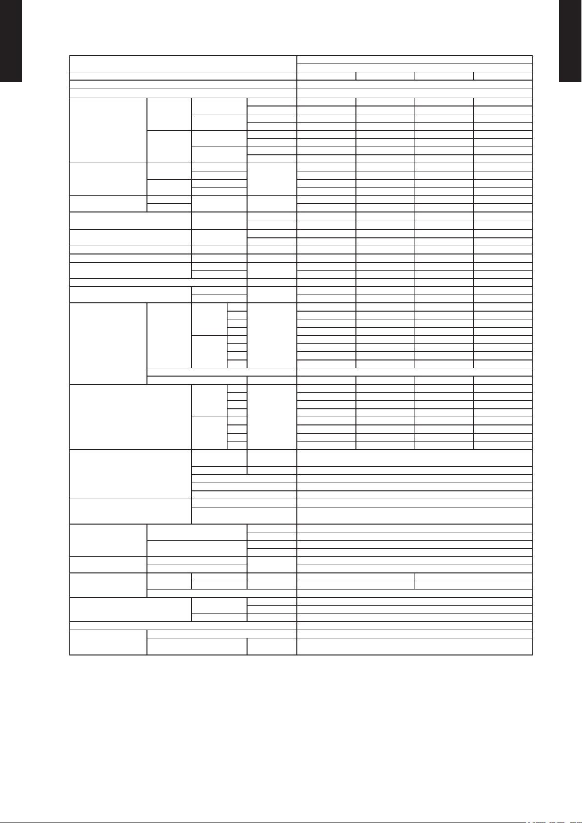
1. SPECIFICATIONS
WALL MOUNTED TYPE RIWH18-36A
Typ e
Model name RIWH1 8ASJ RIWH24ASJ RIWH30AXJ RIWH36AXJ
Power source 208/2 30V ~ 60H z
Available voltage range 187-2 53V
Cooling
Capacity
Heating
Input power
Current
EER Cooling
COP Heating
SEER Cooling Btu/ hW 19. 0 18.0 16. 5 15 .5
HSPF Heating Btu/ hW 10 .6 10.6 9.0 9.0
POWER FACTOR
Moisture removal pints/h (l/h) 4.0 (1 .9) 6.3 (3.0) 9.7 (4.6) 10 .1 (4 .8)
Maxim um operati ng curre nt *1
Fan
Sound pr essure leve l *2
Heat excha nger typ e
Enclosure
Dimensions
( H×W×D )
Weight
Connection pipe
Operation range
Remote controller type Wireless
Drain pipe
Cooling
Heating
Cooling
Heating 5.8 8.5 12. 3 14.8
Airow
rate
Type × Q'ty Cross o w fan × 1
Motor output W 42 42 42 65
Net
Gross
Net
Gross 40 (18 )
Size
Method Flare
Material PVC
Size
Rated
Min-Max
Rated
Min-Max
Rated
Max 1.63 2.50 3.42 4.01
Rated 1.28 5 1.925 2.80 3.39
Max 2.06 2.54 3.28 3.50
Rated A
Cooling
Heating 96 9 8 99 99
Cooling
Heating 11. 8 13.8 18.8 18. 8
Cooling
Heating
Cooling
Heating
Dimensions
(H × W × D)
Fin pitch FPI Main:21, Sub:18
Rows x Sta ges Main:2×18, Sub1:1×4, Sub2:1×4
Pipe type Copper
Fin type Aluminum
Material Polystyrene
Color
Liquid
Gas Ø 1/2 (Ø 12.70) Ø 5/8 (Ø 15.88)
Cooling
Heating °F (°C) 8 8 (30) or less
High
Med 435 (740) 530 (9 00) 53 0 (900) 5 30 (90 0)
Low 36 5 (620) 435 (740) 435 (740) 435 (740)
Quiet 306 (5 20) 36 5 (620) 3 65 (620) 365 (6 20)
High 541 ( 920 ) 6 47 (1,100) 677 (1,15 0) 69 4 (1,18 0)
Med 435 (740) 530 (9 00) 53 0 (900) 5 30 (90 0)
Low 36 5 (620) 435 (740) 435 (740) 435 (740)
Quiet 318 (5 40) 3 65 (620) 365 (6 20) 36 5 (620)
High
Med 35 41 42 42
Low 31 35 37 37
Quiet 26 31 32 32
High 43 47 49 50
Med 36 42 42 42
Low 33 36 37 37
Quiet 28 33 33 33
kW 5.28 7.0 3 8.79 9.70
Btu/h 18,000 24,000 30,000 33,000
kW 0.90 - 5.28 0.90 - 7.30 2.90 - 9.50 2.90 - 10.0 0
Btu/h 3,100 - 19,000 3,100 - 25,000 9,900-32,400 9,900-34,100
kW 5.28 7.0 3 8.79 9.96
Btu/h 18,000 24,000 30,000 34,000
kW 2.05 - 5.86 2.20 - 7.91 2.34 - 9.70 2. 99 - 10.26
Btu/h 7,000 - 20,000 7,500-27,000 8,000 - 33,000 10,200-35,000
kW
kW/kW 3.67 2.93 2.78 2.50
Btu/hW 12 .5 10. 0 9.5 8.5
kW/kW 4 .11 3.65 3.1 4 2.94
Btu/hW 14 .0 12. 5 10.7 10 .0
%
A
CFM
(m3/h)
dB(A)
in. ( mm)
mm 320 × 9 98 × 238
inch 12-10/16 × 39 -5/16 × 9 -6/16
mm 329 × 1090 × 4 20
inch 12-15/16 × 42-15/16 × 16 -9/16
lbs. (kg)
in. ( mm)
°F (° C) 64 to 90 (18 to 32)
%RH 80 or les s
mm
(Reference in.)
1.44 2.40 3 .16 3.88
6.4 10.5 13. 8 17. 0
98 99 99 99
8.3 11. 8 16.8 18.0
541 (92 0) 659 (1,120) 659 (1,120) 6 94 ( 1,18 0)
42 47 47 50
Main:14-14/16 x 32-12/16 x 1-1/16 (378×832× 26.6)
Sub: 3- 5/16 x 32-12/16 x 8/16 (84× 832×13.3)
Ø 1/4 (Ø 6.35) Ø 3/8 (Ø 9.52)
WALL MOUNTED
INVERTER HEAT PUMP
WHITE
Approx imate col or of MUNS ELL N9.2 5/
31 (14)
Ø12 (15 /32) (I. D.)
Ø16 (5/8) (O. D.)
WALL MOUNTED TYPE
RIWH18-36A
NOTE :
• Specications are based on the following conditions.
Cooling : Indoor temperature of 80°F (26.67°C) DB / 67°F (19.44°C) WB, and outdoor temperature of 95°F (35°C) DB / 75°F (23.9°C) WB.
Heating : Indoor temperature of 70°F (21.11°C) DB / 59°F (15°C) WB, and outdoor temperature of 47°F (8.33°C) DB / 43°F (6.11°C) WB.
Pipe length : 24ft.7in (7.5m), Height difference:0 m. (Outdoor unit-Indoor unit)
• The protective function might work when using it outside the operation range.
*1: The maxim um curre nt is the ma ximum valu e when ope rated wit hin the op eration range.
*2: Thes e are the measured values in the ma nufacturer’s ane choic ch amber.
Because of the sur roundin g sound env ironmen t, the soun d levels measured in ac tual inst allati on condi tions might be higher than the s pecied values here.
- (01 - 01) -
Page 5
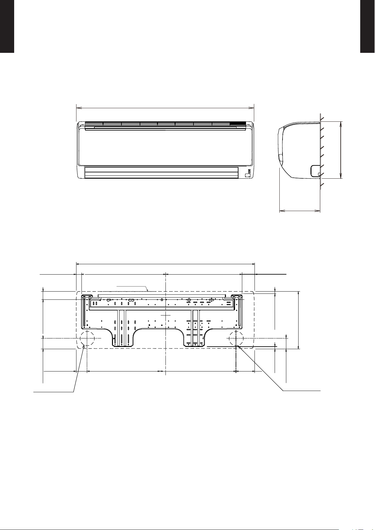
2. DIMENSIONS
WALL MOUNTED TYPE RIWH18-36A
MODEL : RIWH18ASJ, RIWH24ASJ, RIWH30AXJ, RIWH36AXJ
Unit : in (mm)
39-5/16 (998)
9 (238)
WALL MOUNTED TYPE
RIWH18-36A
12-5/8 (320)
1-1/8 (28)
1-13/16 (46)
2-3/16 (56)
Ø 3-1/8 (80) hole
Piping inlet
39-5/16 (998)
18-9/16 (471)
17 (432)
Outline of unit
17-1/4 (438)2-3/8 (61) 4 (102)15-5/8 (397)
2-5/8 (67)
11/16 (17)
12-5/8 (320)
3/8 (10)
2-3/16 (56)
Ø 3-1/8 (80) hole
Piping inlet
- (01 - 02) -
Page 6

WALL MOUNTED TYPE RIWH18-36A
INSTALLATION PLACE
Outline of unit
3 (52) or more 3 (53) or more
Unit : in (mm)
4 (80) or more
3 (63) or more
WALL MOUNTED TYPE
RIWH18-36A
4 (80) or more
5 (120) or more
60 (1500) or more
- (01 - 03) -
71 (1800) or more
Page 7
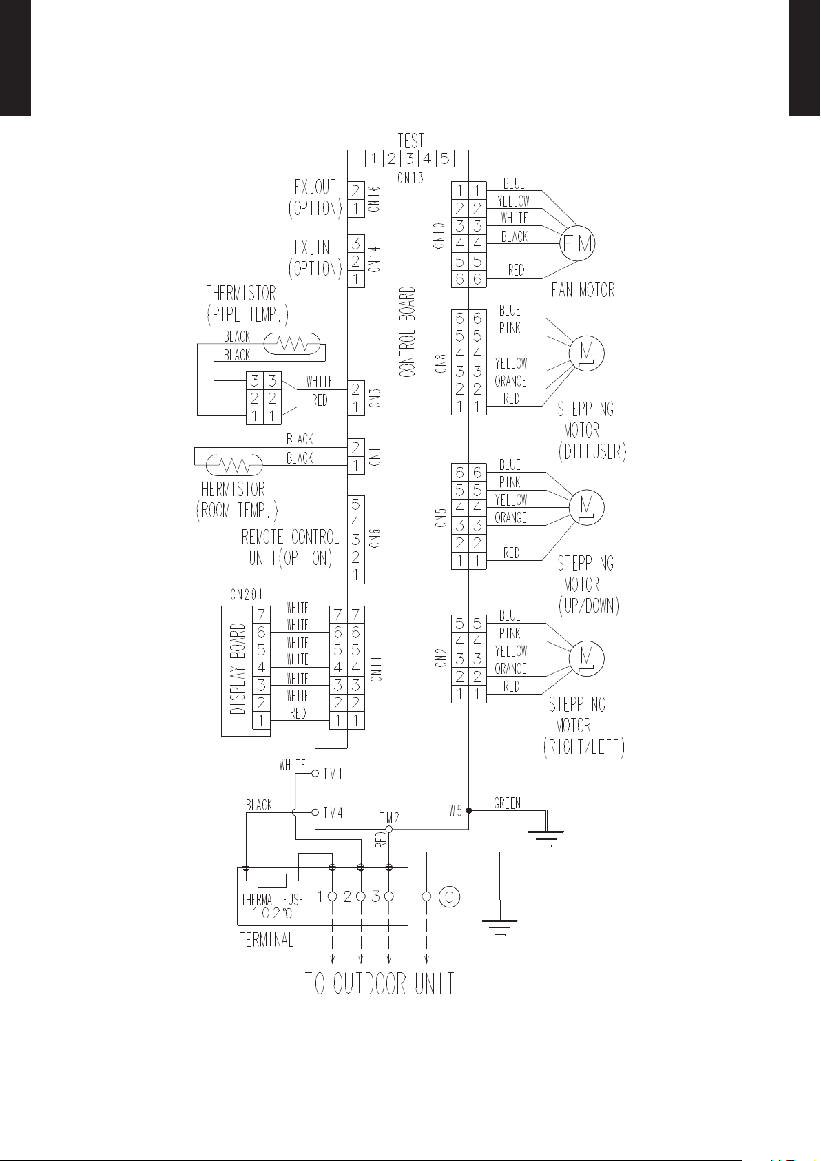
3. WIRING DIAGRAMS
WALL MOUNTED TYPE RIWH18-36A
MODEL : RIWH18ASJ, RIWH24ASJ, RIWH30AXJ, RIWH36AXJ
WALL MOUNTED TYPE
RIWH18-36A
- (01 - 04) -
Page 8
4. CAPACITY TABLE
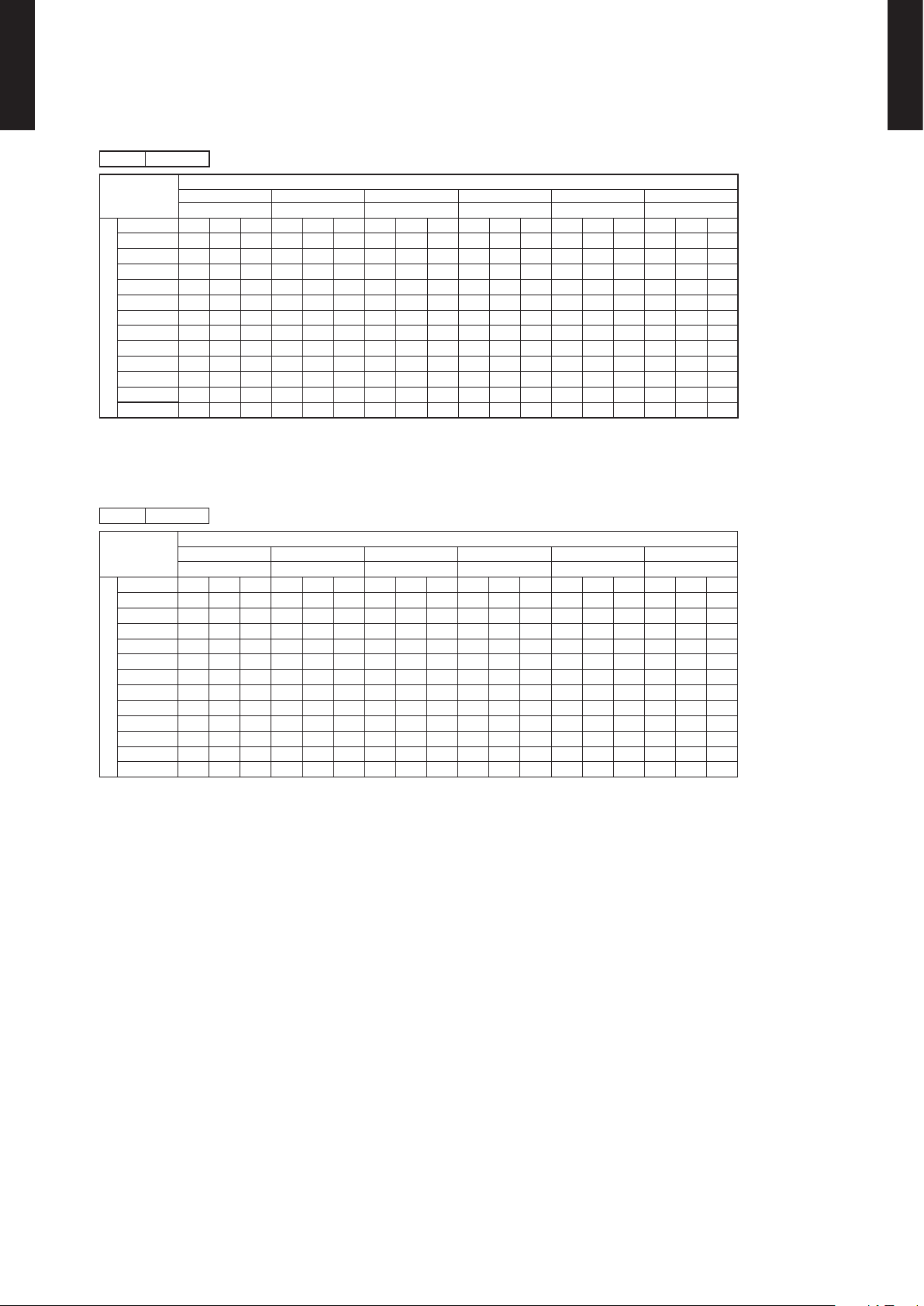
4-1. COOLING CAPACITY
WALL MOUNTED TYPE RIWH18-36A
MODEL : RIWH18ASJ
AFR 541
64°FDB 70°FDB 75°FDB 80°FDB 85°FDB 90°FDB
°FDB TC SHC IP TC SHC IP TC SHC IP TC SHC IP TC SHC IP TC SHC IP
14 15.8 11.8 0.50 17.6 13.1 0.50 19.4 14.5 0.53 20.0 14.9 0.51 21.2 15.8 0.51 22.4 16.7 0.53
23 15.5 11.6 0.54 17.3 12.9 0.54 19.1 14.2 0.57 19.7 14.6 0.56 20.8 15.5 0.56 22.0 16.4 0.58
32 15.3 11.4 0.56 17.0 12.7 0.56 18.8 14.0 0.59 19.4 14.4 0.58 20.5 15.3 0.58 21.7 16.2 0.59
41 15.1 11.2 0.57 16.8 12.5 0.57 18.5 13.8 0.60 19.1 14.2 0.59 20.2 15.1 0.59 21.3 15.9 0.61
50 14.8 11.0 0.58 16.5 12.3 0.59 18.2 13.5 0.62 18.7 14.0 0.60 19.9 14.8 0.60 21.0 15.6 0.62
59 14.6 10.8 0.62 16.2 12.1 0.62 17.9 13.3 0.66 18.4 13.7 0.64 19.5 14.5 0.64 20.7 15.4 0.66
67 16.7 13.3 1.00 18.6 13.4 1.02 20.5 14.6 1.04 21.2 15.8 1.04 22.4 15.7 1.05 23.7 16.8 1.06
77 16.0 12.7 1.13 17.8 12.8 1.14 19.6 13.9 1.17 20.2 15.0 1.17 21.4 15.0 1.18 22.6 16.0 1.19
Outdoor temperature
87 15.2 12.0 1.26 17.0 12.1 1.27 18.7 13.2 1.30 19.3 14.3 1.31 20.5 14.2 1.32 21.6 15.2 1.33
95 14.2 11.3 1.39 15.8 11.4 1.42 17.4 12.4 1.43 18.0 13.4 1.44 19.1 13.3 1.45 20.2 14.2 1.46
104 12.9 9.9 1.37 14.4 10.0 1.39 15.8 10.9 1.42 16.3 11.8 1.42 17.3 11.7 1.43 18.3 12.5 1.45
115 12.0 9.1 1.34 13.4 9.1 1.37 14.8 9.9 1.39 15.2 10.7 1.39 16.1 10.7 1.42 17.0 11.4 1.43
AFR : Air ow rate (CF M)
TC : Total capacity (kBtu/h)
SHC : Sensible H eat capac ity (kBt u/h)
IP : Input Power (kW )
AFR 920
°CDB TC SHC IP TC SHC IP TC SHC IP TC SHC IP TC SHC IP TC SHC IP
-10.0 4.63 3.45 0.50 5.16 3.85 0.50 5.69 4.24 0.53 5.86 4.37 0.51 6.20 4.62 0.51 6.56 4.89 0.53
-5.0 4.56 3.39 0.54 5.08 3.78 0.54 5.60 4.16 0.57 5.77 4.29 0.56 6.11 4.54 0.56 6.46 4.80 0.58
0.0 4.49 3.34 0.56 5.00 3.72 0.56 5.51 4.10 0.59 5.68 4.23 0.58 6.01 4.48 0.58 6.36 4.74 0.59
5.0 4.41 3.29 0.57 4.92 3.67 0.57 5.42 4.04 0.60 5.59 4.16 0.59 5.92 4.41 0.59 6.25 4.66 0.61
10.0 4.34 3.23 0.58 4.84 3.60 0.59 5.33 3.97 0.62 5.49 4.09 0.60 5.82 4.34 0.60 6.15 4.58 0.62
15.0 4.27 3.18 0.62 4.76 3.54 0.62 5.24 3.90 0.66 5.40 4.02 0.64 5.73 4.26 0.64 6.05 4.50 0.66
19.4 4.90 3.91 1.00 5.46 3.93 1.02 6.02 4.28 1.04 6.21 4.63 1.04 6.58 4.60 1.05 6.95 4.91 1.06
25.0 4.68 3.72 1.13 5.21 3.75 1.14 5.75 4.08 1.17 5.92 4.40 1.17 6.27 4.39 1.18 6.63 4.68 1.19
Outdoor temperature
30.6 4.47 3.52 1.26 4.98 3.55 1.27 5.49 3.87 1.30 5.66 4.18 1.31 5.99 4.17 1.32 6.34 4.44 1.33
35.0 4.17 3.31 1.39 4.64 3.34 1.42 5.11 3.64 1.43 5.28 3.93 1.44 5.59 3.91 1.45 5.91 4.17 1.46
40.0 3.78 2.92 1.37 4.21 2.93 1.39 4.64 3.20 1.42 4.78 3.45 1.42 5.07 3.44 1.43 5.35 3.66 1.45
46.1 3.52 2.66 1.34 3.92 2.67 1.37 4.32 2.92 1.39 4.45 3.14 1.39 4.73 3.13 1.42 4.99 3.34 1.43
54°FWB 60°FWB 63°FWB 67°FWB 71°FWB 73°FWB
17.8°CDB 21.1°CDB 23.9°CDB 26.7°CDB 29.4°CDB 32.2°CDB
12.2°CWB 15.6°CWB 17.2°CWB 19.4°CWB 21.7°CWB 22.8°CWB
Indoor temperature
Indoor temperature
WALL MOUNTED TYPE
RIWH18-36A
AFR : Air ow rate (m3/h)
TC : Total capa city (kW )
SHC : Sensible H eat capac ity (kW)
IP : Input Power (kW )
- (01 - 05) -
Page 9

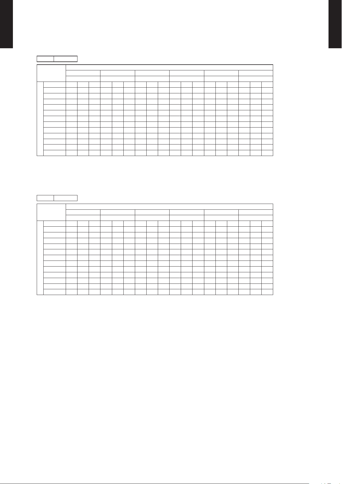
WALL MOUNTED TYPE RIWH18-36A
MODEL : RIWH24ASJ
AFR 659
64°FDB 70°FDB 75°FDB 80°FDB 85°FDB 90°FDB
°FDB TC SHC IP TC SHC IP TC SHC IP TC SHC IP TC SHC IP TC SHC IP
14 21.1 14.9 0.83 23.5 16.6 0.84 25.9 18.3 0.88 26.6 18.9 0.86 28.2 20.0 0.86 29.8 21.2 0.89
23 20.7 14.7 0.90 23.1 16.3 0.90 25.5 18.0 0.95 26.2 18.6 0.93 27.8 19.7 0.93 29.4 20.8 0.96
32 20.4 14.5 0.93 22.7 16.1 0.94 25.1 17.8 0.99 25.8 18.3 0.96 27.3 19.4 0.96 28.9 20.5 0.99
41 20.1 14.2 0.95 22.4 15.9 0.95 24.7 17.5 1.00 25.4 18.0 0.98 26.9 19.1 0.98 28.5 20.2 1.01
50 19.7 14.0 0.97 22.0 15.6 0.98 24.3 17.2 1.03 25.0 17.7 1.00 26.5 18.8 1.01 28.0 19.8 1.04
59 19.7 13.7 1.04 21.9 15.3 1.04 24.2 16.9 1.10 24.9 17.4 1.07 26.4 18.4 1.07 27.9 19.5 1.10
67 22.3 16.9 1.67 24.8 17.0 1.71 27.4 18.5 1.73 28.2 20.0 1.73 29.9 19.9 1.75 31.6 21.3 1.77
77 21.3 16.1 1.88 23.7 16.2 1.90 26.1 17.7 1.94 26.9 19.1 1.94 28.5 19.0 1.96 30.2 20.2 1.98
Outdoor temperature
87 20.2 15.3 2.10 22.5 15.4 2.12 24.8 16.8 2.16 25.5 18.1 2.18 27.0 18.0 2.20 28.6 19.2 2.22
95 19.0 14.3 2.32 21.1 14.4 2.36 23.3 15.7 2.38 24.0 17.0 2.40 25.4 16.9 2.42 26.9 18.0 2.44
104 17.1 12.6 2.28 19.1 12.7 2.32 21.0 13.9 2.36 21.6 14.9 2.36 22.9 14.9 2.38 24.2 15.8 2.42
115 16.1 11.5 2.24 17.9 11.5 2.28 19.7 12.6 2.32 20.3 13.6 2.32 21.6 13.5 2.36 22.7 14.4 2.38
AF R : Air ow rat e (CFM)
TC : Total capacity (kBtu/h)
SH C : Sensibl e Heat cap acity (k Btu/h)
IP : I nput Power (k W)
AFR 1,120
°CDB TC SHC IP TC SHC IP TC SHC IP TC SHC IP TC SHC IP TC SHC IP
-10.0 6.17 4.38 0.83 6.88 4.88 0.84 7.58 5.38 0.88 7.81 5.54 0.86 8.27 5.87 0.86 8.74 6.20 0.89
-5.0 6.08 4.30 0.90 6.77 4.79 0.90 7.46 5.28 0.95 7.69 5.44 0.93 8.14 5.76 0.93 8.61 6.09 0.96
0.0 5.98 4.24 0.93 6.66 4.72 0.94 7.34 5.21 0.99 7.57 5.37 0.96 8.02 5.68 0.96 8.47 6.01 0.99
5.0 5.88 4.17 0.95 6.55 4.65 0.95 7.23 5.12 1.00 7.45 5.28 0.98 7.89 5.60 0.98 8.34 5.91 1.01
10.0 5.79 4.10 0.97 6.45 4.57 0.98 7.11 5.04 1.03 7.33 5.19 1.00 7.76 5.50 1.01 8.20 5.81 1.04
15.0 5.77 4.03 1.04 6.43 4.49 1.04 7.09 4.95 1.10 7.31 5.10 1.07 7.75 5.40 1.07 8.19 5.71 1.10
19.4 6.54 4.96 1.67 7.28 4.99 1.71 8.03 5.43 1.73 8.28 5.87 1.73 8.77 5.84 1.75 9.27 6.23 1.77
25.0 6.24 4.72 1.88 6.95 4.75 1.90 7.66 5.18 1.94 7.89 5.59 1.94 8.36 5.57 1.96 8.84 5.93 1.98
Outdoor temperature
30.6 5.91 4.47 2.10 6.59 4.50 2.12 7.27 4.91 2.16 7.48 5.30 2.18 7.93 5.29 2.20 8.39 5.63 2.22
35.0 5.56 4.20 2.32 6.19 4.23 2.36 6.82 4.61 2.38 7.03 4.99 2.40 7.45 4.96 2.42 7.88 5.29 2.44
40.0 5.01 3.70 2.28 5.58 3.71 2.32 6.14 4.06 2.36 6.33 4.38 2.36 6.72 4.36 2.38 7.09 4.64 2.42
46.1 4.71 3.37 2.24 5.23 3.38 2.28 5.77 3.70 2.32 5.95 3.98 2.32 6.32 3.97 2.36 6.67 4.23 2.38
54°FWB 60°FWB 63°FWB 67°FWB 71°FWB 73°FWB
17.8°CDB 21.1°CDB 23.9°CDB 26.7°CDB 29.4°CDB 32.2°CDB
12.2°CWB 15.6°CWB 17.2°CWB 19.4°CWB 21.7°CWB 22.8°CWB
Indoor temperature
Indoor temperature
WALL MOUNTED TYPE
RIWH18-36A
AF R : Air ow rat e (m3/h)
TC : Total c apacit y (kW)
SH C : Sensibl e Heat cap acity (kW )
IP : I nput Power (k W)
- (01 - 06) -
Page 10
WALL MOUNTED TYPE RIWH18-36A
MODEL : RIWH30AXJ
AFR 659
64°FDB 70°FDB 75°FDB 80°FDB 85°FDB 90°FDB
°FDB TC SHC IP TC SHC IP TC SHC IP TC SHC IP TC SHC IP TC SHC IP
14 25.7 18.3 0.80 28.6 18.4 0.81 31.5 20.1 0.82 32.5 21.7 0.83 34.5 21.6 0.84 36.4 23.0 0.84
23 25.7 18.7 0.93 28.6 18.8 0.94 31.5 20.5 0.95 32.5 22.1 0.96 34.5 22.0 0.97 36.4 23.5 0.98
32 25.7 19.0 1.05 28.6 19.2 1.07 31.5 20.9 1.08 32.5 22.6 1.09 34.4 22.5 1.10 36.4 23.9 1.11
41 25.7 18.3 1.17 28.6 18.4 1.19 31.5 20.1 1.21 32.5 21.7 1.22 34.4 21.6 1.23 36.4 23.0 1.24
50 25.6 18.7 1.33 28.5 18.8 1.35 31.4 20.5 1.37 32.4 22.1 1.37 34.3 22.0 1.39 36.3 23.5 1.40
59 25.1 18.2 1.47 28.0 18.4 1.49 30.8 20.0 1.51 31.8 21.6 1.52 33.7 21.5 1.53 35.6 22.9 1.55
67 24.4 18.0 1.71 27.2 18.2 1.74 30.0 19.8 1.76 30.9 21.4 1.77 32.8 21.3 1.79 34.7 22.7 1.81
77 26.3 19.1 2.45 29.3 19.2 2.49 32.4 20.9 2.53 33.4 22.6 2.54 35.4 22.5 2.57 37.4 24.0 2.59
Outdoor temperature
87 25.1 18.4 2.74 27.9 18.5 2.79 30.8 20.2 2.83 31.7 21.8 2.84 33.6 21.7 2.87 35.5 23.1 2.90
95 23.7 17.6 3.05 26.4 17.7 3.10 29.1 19.4 3.14 30.0 20.9 3.16 31.8 20.8 3.19 33.6 22.2 3.22
104 22.1 16.8 3.35 24.7 16.9 3.40 27.2 18.4 3.45 28.0 19.9 3.47 29.7 19.8 3.50 31.4 21.1 3.54
115 16.9 14.0 2.80 18.8 14.1 2.84 20.7 15.4 2.88 21.3 16.6 2.90 22.6 16.6 2.93 23.9 17.7 2.96
AF R : Air ow rat e (CFM)
TC : Total capacity (kBtu/h)
SH C : Sensibl e Heat cap acity (k Btu/h)
IP : I nput Power (k W)
AFR 1,120
°CDB TC SHC IP TC SHC IP TC SHC IP TC SHC IP TC SHC IP TC SHC IP
-10.0 7.53 5.37 0.80 8.39 5.40 0.81 9.25 5.89 0.82 9.53 6.36 0.83 10.10 6.34 0.84 10.68 6.75 0.84
-5.0 7.53 5.48 0.93 8.38 5.51 0.94 9.24 6.01 0.95 9.53 6.49 0.96 10.10 6.46 0.97 10.67 6.88 0.98
0.0 7.52 5.58 1.05 8.38 5.61 1.07 9.24 6.12 1.08 9.52 6.61 1.09 10.09 6.59 1.10 10.66 7.02 1.11
5.0 7.52 5.36 1.17 8.37 5.40 1.19 9.23 5.88 1.21 9.52 6.35 1.22 10.09 6.33 1.23 10.66 6.74 1.24
10.0 7.50 5.47 1.33 8.35 5.51 1.35 9.21 6.01 1.37 9.49 6.49 1.37 10.06 6.46 1.39 10.63 6.88 1.40
15.0 7.36 5.35 1.47 8.20 5.38 1.49 9.03 5.87 1.51 9.31 6.34 1.52 9.87 6.31 1.53 10.43 6.72 1.55
19.4 7.16 5.29 1.71 7.98 5.32 1.74 8.80 5.80 1.76 9.07 6.27 1.77 9.61 6.24 1.79 10.16 6.65 1.81
25.0 7.72 5.60 2.45 8.60 5.63 2.49 9.48 6.14 2.53 9.77 6.63 2.54 10.36 6.60 2.57 10.95 7.03 2.59
Outdoor temperature
30.6 7.35 5.39 2.74 8.19 5.42 2.79 9.02 5.91 2.83 9.30 6.39 2.84 9.86 6.36 2.87 10.42 6.78 2.90
35.0 6.94 5.17 3.05 7.74 5.20 3.10 8.53 5.67 3.14 8.79 6.12 3.16 9.32 6.10 3.19 9.84 6.50 3.22
40.0 6.49 4.93 3.35 7.23 4.95 3.40 7.97 5.40 3.45 8.22 5.84 3.47 8.71 5.81 3.50 9.20 6.19 3.54
46.1 4.94 4.12 2.80 5.51 4.14 2.84 6.07 4.52 2.88 6.26 4.88 2.90 6.63 4.86 2.93 7.01 5.17 2.96
54°FWB 60°FWB 63°FWB 67°FWB 71°FWB 73°FWB
17.8°CDB 21.1°CDB 23.9°CDB 26.7°CDB 29.4°CDB 32.2°CDB
12.2°CWB 15.6°CWB 17.2°CWB 19.4°CWB 21.7°CWB 22.8°CWB
Indoor temperature
Indoor temperature
WALL MOUNTED TYPE
RIWH18-36A
AF R : Air ow rat e (m3/h)
TC : Total c apacit y (kW)
SH C : Sensibl e Heat cap acity (kW )
IP : I nput Power (k W)
- (01 - 07) -
Page 11

WALL MOUNTED TYPE RIWH18-36A
MODEL : RIWH36AXJ
AFR 694
64°FDB 70°FDB 75°FDB 80°FDB 85°FDB 90°FDB
°FDB TC SHC IP TC SHC IP TC SHC IP TC SHC IP TC SHC IP TC SHC IP
14 27.6 19.9 1.01 30.8 20.0 1.03 33.9 21.9 1.04 35.0 23.6 1.05 37.1 23.5 1.06 39.2 25.1 1.07
23 27.6 20.3 1.17 30.8 20.4 1.19 33.9 22.3 1.21 34.9 24.1 1.21 37.0 24.0 1.22 39.1 25.5 1.24
32 27.6 20.7 1.33 30.7 20.8 1.35 33.9 22.7 1.37 34.9 24.5 1.38 37.0 24.4 1.39 39.1 26.0 1.41
41 27.6 19.9 1.48 30.7 20.0 1.51 33.9 21.8 1.53 34.9 23.6 1.54 37.0 23.5 1.55 39.1 25.0 1.57
50 27.5 20.3 1.68 30.6 20.4 1.70 33.8 22.3 1.73 34.8 24.0 1.74 36.9 23.9 1.76 39.0 25.5 1.77
59 27.3 20.2 1.85 30.4 20.3 1.88 33.6 22.1 1.91 34.6 23.9 1.92 36.7 23.8 1.94 38.7 25.4 1.96
67 26.3 19.6 2.16 29.3 19.7 2.20 32.3 21.5 2.23 33.3 23.2 2.24 35.3 23.1 2.27 37.3 24.6 2.29
77 28.3 20.8 3.10 31.6 20.9 3.15 34.8 22.8 3.20 35.9 24.6 3.21 38.0 24.5 3.25 40.2 26.1 3.28
Outdoor temperature
87 27.0 20.0 3.47 30.0 20.1 3.52 33.1 21.9 3.58 34.1 23.7 3.60 36.2 23.6 3.63 38.2 25.1 3.67
95 25.5 19.2 3.86 28.4 19.3 3.92 31.3 21.0 3.98 33.0 21.8 3.88 34.2 22.6 4.04 36.1 24.1 4.08
104 23.8 18.2 4.23 26.5 18.3 4.30 29.2 20.0 4.37 30.1 21.6 4.39 31.9 21.5 4.43 33.8 22.9 4.48
115 18.1 15.2 3.54 20.2 15.3 3.59 22.3 16.7 3.65 22.9 18.0 3.67 24.3 17.9 3.70 25.7 19.1 3.74
AF R : Air ow rat e (CFM)
TC : Total capacity (kBtu/h)
SH C : Sensibl e Heat cap acity (k Btu/h)
IP : I nput Power (k W)
AFR 1,180
°CDB TC SHC IP TC SHC IP TC SHC IP TC SHC IP TC SHC IP TC SHC IP
-10.0 8.10 5.84 1.01 9.02 5.88 1.03 9.94 6.41 1.04 10.25 6.92 1.05 10.86 6.89 1.06 11.48 7.34 1.07
-5.0 8.09 5.95 1.17 9.01 5.99 1.19 9.94 6.53 1.21 10.24 7.05 1.21 10.86 7.02 1.22 11.47 7.48 1.24
0.0 8.09 6.06 1.33 9.01 6.10 1.35 9.93 6.65 1.37 10.24 7.18 1.38 10.85 7.15 1.39 11.47 7.62 1.41
5.0 8.08 5.83 1.48 9.00 5.87 1.51 9.92 6.40 1.53 10.23 6.91 1.54 10.84 6.88 1.55 11.46 7.33 1.57
10.0 8.06 5.95 1.68 8.98 5.98 1.70 9.90 6.53 1.73 10.21 7.05 1.74 10.82 7.02 1.76 11.43 7.48 1.77
15.0 8.01 5.92 1.85 8.92 5.95 1.88 9.83 6.49 1.91 10.14 7.01 1.92 10.75 6.98 1.94 11.35 7.44 1.96
19.4 7.70 5.75 2.16 8.58 5.78 2.20 9.46 6.30 2.23 9.75 6.81 2.24 10.33 6.78 2.27 10.92 7.22 2.29
25.0 8.30 6.08 3.10 9.25 6.12 3.15 10.19 6.67 3.20 10.51 7.21 3.21 11.14 7.18 3.25 11.77 7.65 3.28
Outdoor temperature
30.6 7.90 5.86 3.47 8.80 5.89 3.52 9.70 6.43 3.58 10.00 6.94 3.60 10.60 6.91 3.63 11.20 7.36 3.67
35.0 7.47 5.61 3.86 8.32 5.65 3.92 9.17 6.16 3.98 9.70 6.39 3.88 10.02 6.62 4.04 10.58 7.06 4.08
40.0 6.98 5.35 4.23 7.77 5.38 4.30 8.57 5.87 4.37 8.83 6.33 4.39 9.36 6.31 4.43 9.89 6.72 4.48
46.1 5.31 4.45 3.54 5.92 4.48 3.59 6.52 4.89 3.65 6.73 5.28 3.67 7.13 5.26 3.70 7.53 5.60 3.74
54°FWB 60°FWB 63°FWB 67°FWB 71°FWB 73°FWB
17.8°CDB 21.1°CDB 23.9°CDB 26.7°CDB 29.4°CDB 32.2°CDB
12.2°CWB 15.6°CWB 17.2°CWB 19.4°CWB 21.7°CWB 22.8°CWB
Indoor temperature
Indoor temperature
WALL MOUNTED TYPE
RIWH18-36A
AF R : Air ow rat e (m3/h)
TC : Total c apacit y (kW)
SH C : Sensibl e Heat cap acity (kW )
IP : I nput Power (k W)
- (01 - 08) -
Page 12
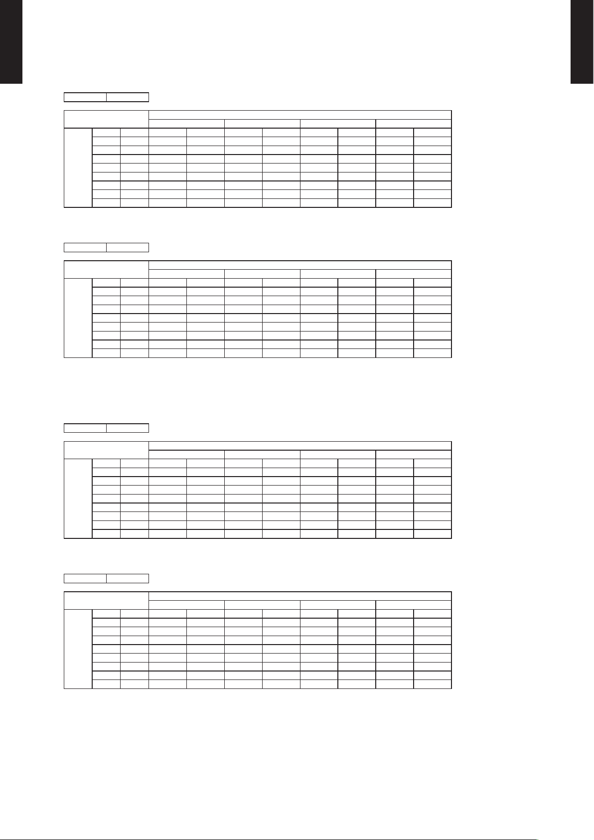
4-2. HEATING CAPACITY
WALL MOUNTED TYPE RIWH18-36A
MODEL : RIWH18ASJ
AFR 5 41
°FDB °FWB TC IP TC IP TC IP TC IP
5 3 16 .2 1.9 8 15. 8 2.01 15.4 2 .18 14.6 2 .14
14 12 1 7.3 1. 87 16.9 1.9 0 16.5 2.13 15 .6 2.02
23 19 18 .1 1.81 17.7 1.84 17.2 2.05 16.3 1.96
32 28 18. 2 1.81 17.8 1. 85 17.3 1.95 16 .5 1.9 6
41 37 19.9 1.92 19.4 1.95 19.0 2.0 0 18.0 2.0 8
47 43 2 1.0 1.98 20. 5 2.01 20.0 2.0 6 19.0 2.14
50 47 23.2 2.01 2 2.7 2.04 22.1 2.0 9 21.0 2.17
Outdoor temperature
59 50 24.0 2.05 23.4 2.09 22.9 2 .10 21.8 2.2 2
AFR : Air ow ra te (CFM)
TC : Total capacity (kBtu/h)
IP : I nput Power (k W)
AFR 920
°CDB °CWB TC IP TC IP TC IP TC IP
-15.0 -16 .1 4.73 1.98 4.64 2.01 4.51 2.18 4.29 2 .14
-10.0 -11 .1 5.08 1.8 7 4.95 1.90 4.8 3 2.13 4.59 2.02
-5.0 - 7.2 5. 30 1.81 5.1 7 1. 84 5.03 2.05 4.78 1.96
0.0 -2. 2 5.3 5 1.81 5. 22 1.8 5 5.08 1.9 5 4.83 1. 96
5.0 2.8 5.84 1.92 5.69 1.9 5 5.57 2.0 0 5.27 2.08
8.3 6 .1 6 .16 1. 98 6.01 2.01 5.86 2.0 6 5.57 2 .14
10.0 8 .3 6.79 2.01 6.65 2.04 6. 47 2.09 6.16 2 .17
Outdoor temperature
15.0 10.0 7.0 4 2.05 6.87 2.09 6.72 2 .10 6.38 2.2 2
AF R : Air ow rat e (m3/h)
TC : Total c apacit y (kW)
IP : I nput Power (k W)
60°FDB 65°FDB 70°FDB 75°FDB
15.6°CDB 18.3°CDB 2 1.1° CDB 23.9°CDB
Indoor temperature
Indoor temperature
WALL MOUNTED TYPE
RIWH18-36A
MODEL : RIWH24ASJ
AFR 647
°FDB °FWB TC IP TC IP TC IP TC IP
5 3 21.8 2.4 4 21.4 2. 48 20.8 2.69 19.8 2.6 4
14 12 23.4 2.30 22.8 2.3 4 22.3 2.62 21.1 2.49
23 19 24 .4 2.23 23.8 2. 27 23.2 2 .53 22.0 2 .41
32 28 24.6 2.23 2 4.1 2. 28 23.4 2 .40 22.3 2.42
41 37 26.9 2.37 26.2 2. 41 25.6 2.46 24.3 2.56
47 43 28. 4 2.44 2 7.7 2.48 2 7.0 2.54 25.6 2.6 4
50 47 31.3 2.4 8 30.6 2.52 29.8 2.58 28.4 2.6 8
Outdoor temperature
59 50 32.4 2.5 3 31.6 2. 57 31.0 2.59 29.4 2.73
AFR : Air ow ra te (CFM)
TC : Total capacity (kBtu/h)
IP : I nput Power (k W)
AFR 1,10 0
°CDB °CWB TC IP TC IP TC IP TC IP
-15.0 -16 .1 6.3 9 2.44 6.26 2.4 8 6.09 2.69 5.7 9 2.64
-10.0 -11 .1 6.85 2.30 6.6 9 2.34 6.52 2.6 2 6 .19 2.49
-5.0 - 7.2 7.15 2. 23 6.99 2.27 6.7 9 2.53 6.46 2.41
0.0 -2. 2 7. 22 2.23 7.0 5 2.28 6.8 5 2.40 6.52 2. 42
5.0 2.8 7.88 2.37 7.6 8 2.41 7. 52 2. 46 7. 12 2.56
8.3 6 .1 8. 31 2.44 8.11 2.48 7.91 2.54 7. 52 2. 64
10.0 8 .3 9.1 7 2.48 8.97 2.52 8.74 2 .58 8. 31 2.68
Outdoor temperature
15.0 10.0 9.50 2.53 9.27 2.57 9.07 2.59 8.61 2.73
AF R : Air ow rat e (m3/h)
TC : Total c apacit y (kW)
IP : I nput Power (k W)
60°FDB 65°FDB 70°FDB 75°FDB
15.6°CDB 18.3°CDB 2 1.1° CDB 23.9°CDB
Indoor temperature
Indoor temperature
- (01 - 09) -
Page 13
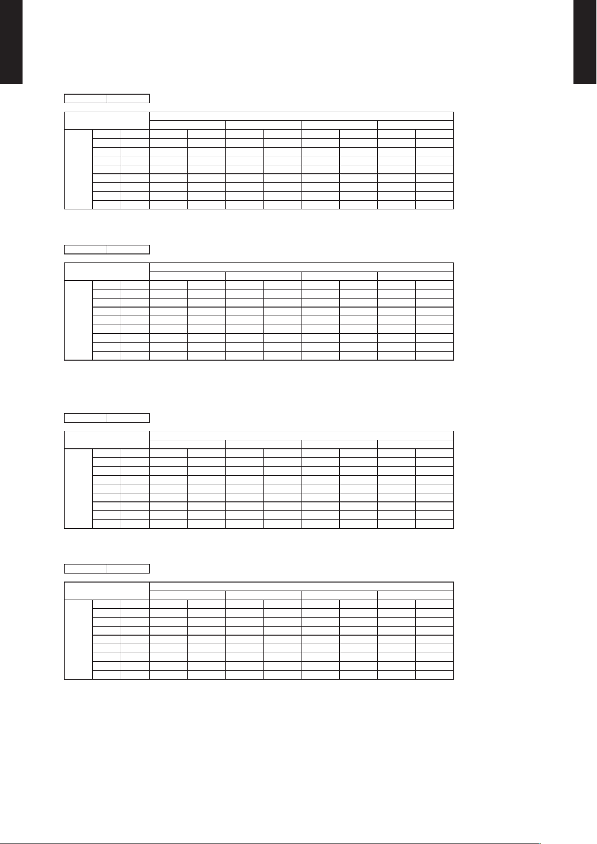
WALL MOUNTED TYPE RIWH18-36A
MODEL : RIWH30AXJ
AFR 677
WALL MOUNTED TYPE
RIWH18-36A
°FDB °FWB TC IP TC IP TC IP TC IP
5 3 23.2 3.7 8 22.7 3.8 6 22.1 3.94 21. 0 4.10
14 12 25.0 3.78 24.4 3.86 23.8 3.93 22 .6 4.09
23 19 28 .8 3.79 28.1 3.87 2 7.5 3.95 2 6.1 4.11
32 28 31. 6 3.76 3 0.9 3.84 3 0.1 3 .91 28.6 4.07
41 37 34.6 3.80 3 3.8 3.88 32.9 3.96 31.3 4 .12
47 43 3 4.7 3 .15 33.8 3.21 33.0 3.2 8 31.4 3.41
50 47 3 5.7 3 .14 34. 8 3.20 3 4.0 3.27 32.3 3. 40
Outdoor temperature
59 50 34.4 2 .74 33.6 2.80 32.8 2. 86 3 1.1 2.97
AFR : Air ow ra te (CFM)
TC : Total capacity (kBtu/h)
IP : I nput Power (k W)
AFR 1,15 0
°CDB °CWB TC IP TC IP TC IP TC IP
-15.0 -16 .1 6. 81 3.78 6. 65 3.86 6.48 3 .94 6 .16 4.10
-10.0 -11 .1 7.33 3.78 7.1 5 3.8 6 6.98 3.93 6.6 3 4.09
-5.0 - 7.2 8. 45 3.79 8. 25 3.87 8.05 3.9 5 7.65 4.11
0.0 -2. 2 9.2 7 3.76 9.05 3. 84 8.83 3.91 8. 38 4.07
5.0 2.8 10.14 3.80 9.90 3.8 8 9.66 3.96 9.17 4.12
8.3 6 .1 10.16 3.15 9.91 3.21 9.70 3 .28 9 .19 3 .41
10.0 8 .3 10.46 3.1 4 10.21 3. 20 9. 96 3.27 9. 47 3.40
Outdoor temperature
15.0 10.0 10.09 2 .74 9.85 2.80 9.61 2. 86 9 .13 2.97
AF R : Air ow rat e (m3/h)
TC : Total c apacit y (kW)
IP : I nput Power (k W)
MODEL : RIWH36AXJ
AFR 694
60°FDB 65°FDB 70°FDB 75°FDB
15.6°CDB 18.3°CDB 2 1.1° CDB 23.9°CDB
Indoor temperature
Indoor temperature
°FDB °FWB TC IP TC IP TC IP TC IP
5 3 24.6 4.04 2 4.1 4.12 23.5 4.20 22.3 4. 28
14 12 26.5 4.03 25.9 4 .11 25.3 4. 20 24.0 4.28
23 19 3 0.6 4.05 29.9 4.1 3 29 .1 4. 22 2 7.7 4. 28
32 28 33.5 4.01 32.7 4.0 9 31.9 4.1 8 3 0.3 4.28
41 37 36.7 4.0 6 35.8 4 .14 34. 9 4.23 33.2 4.2 8
47 43 36.8 3.36 35.9 3.43 35.0 3.50 33.3 3.64
50 47 37. 9 3.35 3 7.0 3. 42 36.1 3.49 34. 3 3.63
Outdoor temperature
59 50 36.5 2.92 35.6 2.99 3 4.8 3.05 33 .0 3 .17
AFR : Air ow ra te (CFM)
TC : Total capacity (kBtu/h)
IP : I nput Power (k W)
AFR 1,18 0
°CDB °CWB TC IP TC IP TC IP TC IP
-15.0 -16 .1 7. 22 4.04 7. 05 4.12 6. 88 4.20 6.5 3 4.28
-10.0 -11 .1 7.7 7 4.03 7.5 9 4.11 7.4 0 4.20 7. 03 4.2 8
-5.0 - 7.2 8.96 4.05 8.75 4.13 8.5 4 4.22 8 .11 4.28
0.0 -2. 2 9.8 3 4.01 9.59 4.0 9 9.36 4 .18 8.8 9 4.28
5.0 2.8 10.75 4. 06 10.5 0 4 .14 10.24 4.23 9.73 4.28
8.3 6 .1 10.7 7 3.36 10. 51 3. 43 10.2 6 3.50 9.75 3.64
10.0 8 .3 11 .10 3.35 10.8 3 3.42 10 .57 3. 49 10.04 3.63
Outdoor temperature
15.0 10.0 10.70 2.92 10.45 2.99 10 .19 3.0 5 9.68 3 .17
AF R : Air ow rat e (m3/h)
TC : Total c apacit y (kW)
IP : I nput Power (k W)
60°FDB 65°FDB 70°FDB 75°FDB
15.6°CDB 18.3°CDB 2 1.1° CDB 23.9°CDB
Indoor temperature
Indoor temperature
- (01 - 10) -
Page 14
5. FAN PERFORMANCE
WALL MOUNTED TYPE RIWH18-36A
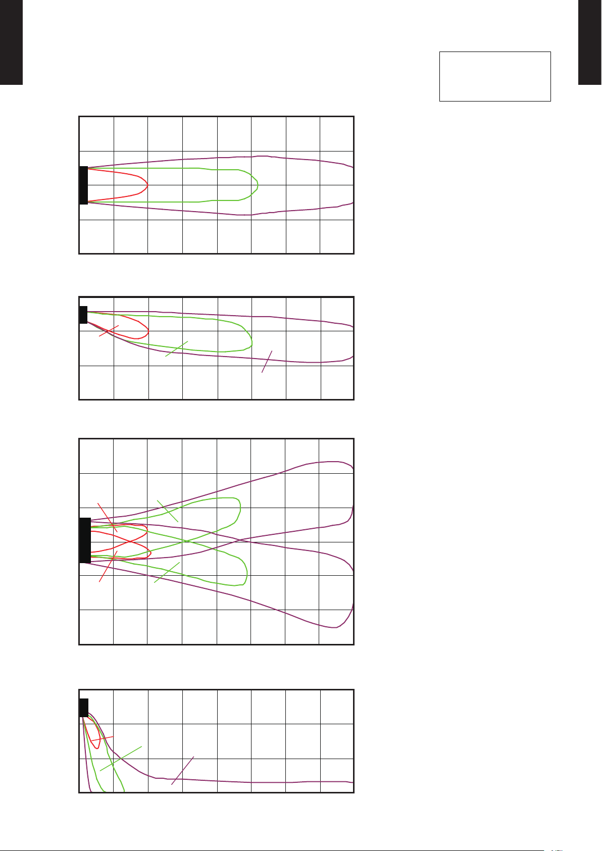
5-1. AIR VELOCITY DISTRIBUTION
MODEL : RIWH18ASJ
(m)
(ft)
2
7
1
3
0
0
1
3
2
7
0 1 2 3 4 5 6 7 8
(m)
(ft)
3
10
2
7
7(2) 3(1) 2(0.5)
7 14 20 27
7(2)
Unit : ft/s (m/s)
Unit : ft/s (m/s)
Conditions:
Fan speed : High
Operation mode : FAN
Voltage : 230V
TOP VIEW
Vertic al air ow direct ion louve r : Up
Horizo ntal air ow dire ction lou ver : Center
(m)
(ft)
WALL MOUNTED TYPE
RIWH18-36A
1
3
3(1)
2(0.5)
0
0
0 1 2 3 4 5 6 7 8
7 14 20 27
(ft)
(m)
3
10
2
7
7(2)
1
3
3(1)
Unit : ft/s (m/s)
2(0.5)
0
0
2(0.5)
1
3
7(2)
2
7
3
10
0 1 2 3 4 5 6 7 8
(ft)
(m)
10
3
3(1)
7 14 20 27
Unit : ft/s (m/s)
SIDE VI EW
Vertic al air ow direct ion louve r : Up
Horizo ntal air ow dire ction lou ver : Center
(m)
(ft)
TOP VIEW
Vertic al air ow direct ion louve r : Up
Horizo ntal air ow dire ction lou ver : Right & Le ft
(m)
(ft)
7
2
7(2)
3(1)
3
1
0
0
0 1 2 3 4 5 6 7 8
7 14 20 27
2(0.5)
- (01 - 11) -
SIDE VI EW
Vertic al air ow direct ion louve r : Down
Horizo ntal air ow dire ction lou ver : Center
(m)
(ft)
Page 15

WALL MOUNTED TYPE RIWH18-36A
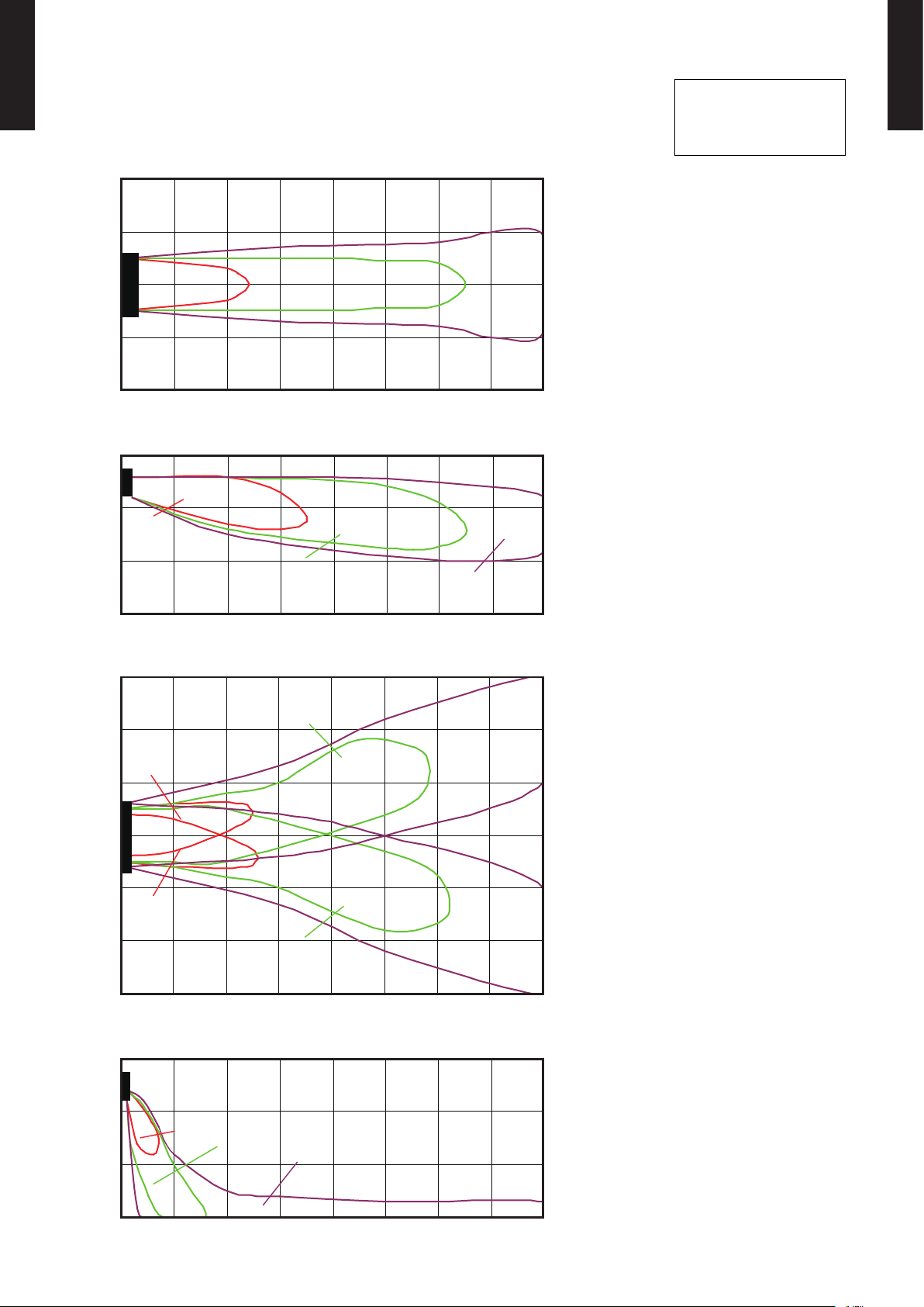
MODEL : RIWH24ASJ
(m)
(ft)
2
7
1
3
0
0
1
3
2
7
0 1 2 3 4 5 6 7 8
(m)
(ft)
3
10
2
7
7(2) 3(1)
7 14 20 27
Unit : ft/s (m/s)
Unit : ft/s (m/s)
7(2)
2(0.5)
Conditions:
Fan speed : High
Operation mode : FAN
Voltage : 230V
TOP VIEW
Vertic al air ow direct ion louve r : Up
Horizo ntal air ow dire ction lou ver : Center
(m)
(ft)
WALL MOUNTED TYPE
RIWH18-36A
1
3
0
0
0 1 2 3 4 5 6 7 8
7 14 20 27
(ft)
(m)
3
10
3(1)
Unit : ft/s (m/s)
3(1)
2
7
7(2)
1
3
0
0
1
3
7(2)
2
7
3
10
0 1 2 3 4 5 6 7 8
7 14 20 27
(ft)
(m)
10
3
3(1)
Unit : ft/s (m/s)
2(0.5)
2(0.5)
2(0.5)
SIDE VI EW
Vertic al air ow direct ion louve r : Up
Horizo ntal air ow dire ction lou ver : Center
(m)
(ft)
TOP VIEW
Vertic al air ow direct ion louve r : Up
Horizo ntal air ow dire ction lou ver : Right & Le ft
(m)
(ft)
7
2
7(2)
3(1)
3
1
0
0
0 1 2 3 4 5 6 7 8
7 14 20 27
2(0.5)
- (01 - 12) -
SIDE VI EW
Vertic al air ow direct ion louve r : Down
Horizo ntal air ow dire ction lou ver : Center
(m)
(ft)
Page 16
WALL MOUNTED TYPE RIWH18-36A
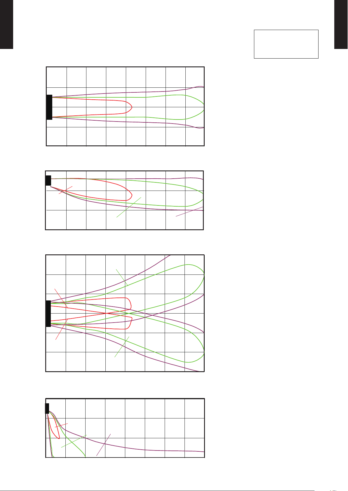
MODEL : RIWH30AXJ
(m)
(ft)
2
7
1
3
0
0
1
3
2
7
0 1 2 3 4 5 6 7 8
(m)
(ft)
3
10
2
7
7(2) 3(1)
7 14 20 27
Unit : ft/s (m/s)
Unit : ft/s (m/s)
7(2)
2(0.5)
Conditions:
Fan speed : High
Operation mode : FAN
Voltage : 230V
TOP VIEW
Vertic al air ow direct ion louve r : Up
Horizo ntal air ow dire ction lou ver : Center
(m)
(ft)
WALL MOUNTED TYPE
RIWH18-36A
1
3
0
0
0 1 2 3 4 5 6 7 8
7 14 20 27
(ft)
(m)
3
10
3(1)
Unit : ft/s (m/s)
3(1)
2
7
7(2)
1
3
0
0
1
3
7(2)
2
7
3
10
0 1 2 3 4 5 6 7 8
7 14 20 27
(ft)
(m)
10
3
3(1)
Unit : ft/s (m/s)
2(0.5)
2(0.5)
2(0.5)
SIDE VI EW
Vertic al air ow direct ion louve r : Up
Horizo ntal air ow dire ction lou ver : Center
(m)
(ft)
TOP VIEW
Vertic al air ow direct ion louve r : Up
Horizo ntal air ow dire ction lou ver : Right & Le ft
(m)
(ft)
7
2
7(2)
3(1)
3
1
0
0
0 1 2 3 4 5 6 7 8
7 14 20 27
2(0.5)
- (01 - 13) -
SIDE VI EW
Vertic al air ow direct ion louve r : Down
Horizo ntal air ow dire ction lou ver : Center
(m)
(ft)
Page 17
WALL MOUNTED TYPE RIWH18-36A
2(0.5)
2(0.5)
3(1)
3(1)
7(2)
7(2)
MODEL : RIWH36AXJ
(m)
(ft)
2
7
1
3
0
0
7(2)
Unit : ft/s (m/s)
3(1)
Conditions:
Fan speed : High
Operation mode : FAN
Voltage : 230V
WALL MOUNTED TYPE
RIWH18-36A
1
3
2
7
0 1 2 3 4 5 6 7 8
7 14 20 27
(ft)
10
7
(m)
3
2
Unit : ft/s (m/s)
7(2)
1
3
3(1)
0
0
0 1 2 3 4 5 6 7 8
7 14 20 27
(ft)
(m)
3
10
2
7
2(0.5)
Unit : ft/s (m/s)
2(0.5)
TOP VIEW
Vertic al air ow direct ion louve r : Up
Horizo ntal air ow dire ction lou ver : Center
(m)
(ft)
SIDE VI EW
Vertic al air ow direct ion louve r : Up
Horizo ntal air ow dire ction lou ver : Center
(m)
(ft)
1
3
0
0
1
3
2
7
3
10
0 1 2 3 4 5 6 7 8
(ft)
(m)
10
3
7
2
3
1
0
0
0 1 2 3 4 5 6 7 8
7(2)
7 14 20 27
3(1)
7 14 20 27
2(0.5)
Unit : ft/s (m/s)
- (01 - 14) -
TOP VIEW
Vertic al air ow direct ion louve r : Up
Horizo ntal air ow dire ction lou ver : Right & Le ft
(m)
(ft)
SIDE VI EW
Vertic al air ow direct ion louve r : Down
Horizo ntal air ow dire ction lou ver : Center
(m)
(ft)
Page 18

5-2. AIR FLOW
WALL MOUNTED TYPE RIWH18-36A
MODEL : RIWH18ASJ
Cooling
z
Fan speed Air ow
920 m
HIGH
256 l/s
541 CFM
740 m
MED
206 l/s
435 CFM
620 m
LOW
172 l/s
365 CFM
520 m
QUIET
144 l/s
WALL MOUNTED TYPE
RIWH18-36A
3
/h
3
/h
3
/h
3
/h
306 CFM
Heating
z
Fan speed Air ow
920 m
HIGH
256 l/s
541 CFM
740 m
MED
206 l/s
435 CFM
620 m
LOW
172 l/s
365 CFM
540 m
3
/h
3
/h
3
/h
3
/h
QUIET
150 l/s
318 CFM
- (01 - 15) -
Page 19

WALL MOUNTED TYPE RIWH18-36A
MODEL : RIWH24ASJ
Cooling
z
Fan speed Air ow
WALL MOUNTED TYPE
RIWH18-36A
HIGH
MED
LOW
QUIET
Heating
z
112 0 m
3
311 l/s
659 CFM
900 m
3
250 l/s
530 CFM
740 m
3
206 l/s
435 CFM
620 m
3
172 l/s
365 CFM
/h
/h
/h
/h
Fan speed Air ow
110 0 m
HIGH
306 l/s
647 CFM
900 m
MED
250 l/s
530 CFM
740 m
LOW
206 l/s
435 CFM
620 m
QUIET
172 l/s
365 CFM
3
/h
3
/h
3
/h
3
/h
- (01 - 16) -
Page 20

WALL MOUNTED TYPE RIWH18-36A
MODEL : RIWH30AXJ
Cooling
z
Fan speed Air ow
WALL MOUNTED TYPE
RIWH18-36A
HIGH
MED
LOW
QUIET
Heating
z
112 0 m
3
311 l/s
659 CFM
900 m
3
250 l/s
530 CFM
740 m
3
206 l/s
435 CFM
620 m
3
172 l/s
365 CFM
/h
/h
/h
/h
Fan speed Air ow
115 0 m
HIGH
319 l/s
677 CFM
900 m
MED
250 l/s
530 CFM
740 m
LOW
206 l/s
435 CFM
620 m
QUIET
172 l/s
365 CFM
3
/h
3
/h
3
/h
3
/h
- (01 - 17) -
Page 21

WALL MOUNTED TYPE RIWH18-36A
MODEL : RIWH36AXJ
Cooling
z
Fan speed Air ow
WALL MOUNTED TYPE
RIWH18-36A
HIGH
MED
LOW
QUIET
Heating
z
118 0 m
3
328 l/s
694 CFM
900 m
3
250 l/s
530 CFM
740 m
3
206 l/s
435 CFM
620 m
3
172 l/s
365 CFM
/h
/h
/h
/h
Fan speed Air ow
118 0 m
HIGH
328 l/s
694 CFM
900 m
MED
250 l/s
530 CFM
740 m
LOW
206 l/s
435 CFM
620 m
QUIET
172 l/s
365 CFM
3
/h
3
/h
3
/h
3
/h
- (01 - 18) -
Page 22

6. OPERATION NOISE
6-1. NOISE LEVEL CURVE
WALL MOUNTED TYPE RIWH18-36A
MODEL : RIWH18ASJ
Cooling
z
80
80
70
70
60
60
50
50
High
40
40
30
30
20
20
Octave band sound p ressure l evel, dB:(0d B=0.0 002µbar)
Octave band sound p ressure l evel, dB:(0d B=0.0 002µbar)
10
10
Quiet
NC-65
NC-60
NC-55
NC-50
NC-45
NC-40
NC-35
NC-30
NC-25
NC-20
NC -15
Heating
z
80
80
70
70
60
60
50
50
40
40
30
30
20
20
Octave band sound p ressure l evel, dB:(0d B=0.0 002µbar)
Octave band sound p ressure l evel, dB:(0d B=0.0 002µbar)
10
10
Quiet
High
NC-65
NC-60
NC-55
NC-50
NC-45
NC-40
NC-35
NC-30
NC-25
NC-20
NC -15
WALL MOUNTED TYPE
RIWH18-36A
0
0
63 125 250 500 1,000 2,000 4,000 8,000
63 125 250 500 1,000 2,000 4,000 8,000
Octave band center frequency,Hz
Octave band cente r frequency,Hz
MODEL : RIWH24ASJ
Cooling
z
80
80
70
70
60
60
50
50
40
40
30
30
Quiet
20
20
Octave band sound p ressure l evel, dB:(0d B=0.0 002µbar)
Octave band sound p ressure l evel, dB:(0d B=0.0 002µbar)
10
10
High
NC-65
NC-60
NC-55
NC-50
NC-45
NC-40
NC-35
NC-30
NC-25
NC-20
NC -15
0
0
63 125 250 500 1,000 2,000 4,000 8,000
63 125 250 500 1,000 2,000 4,000 8,000
Octave band center frequency,Hz
Octave band cente r frequency,Hz
Heating
z
80
80
70
70
60
60
50
50
40
40
30
30
20
20
Octave band sound p ressure l evel, dB:(0d B=0.0 002µbar)
Octave band sound p ressure l evel, dB:(0d B=0.0 002µbar)
10
10
High
Quiet
NC-65
NC-60
NC-55
NC-50
NC-45
NC-40
NC-35
NC-30
NC-25
NC-20
NC -15
0
0
63 125 250 500 1,000 2,000 4,000 8,000
63 125 250 500 1,000 2,000 4,000 8,000
Octave band center frequency,Hz
Octave band cente r frequency,Hz
- (01 - 19) -
0
0
63 125 250 500 1,000 2,000 4,000 8,000
63 125 250 500 1,000 2,000 4,000 8,000
Octave band center frequency,Hz
Octave band cente r frequency,Hz
Page 23

WALL MOUNTED TYPE RIWH18-36A
MODEL : RIWH30AXJ
WALL MOUNTED TYPE
RIWH18-36A
Cooling
z
80
80
70
70
60
60
50
50
40
40
30
30
Quiet
20
20
Octave band sound p ressure l evel, dB:(0d B=0.0 002µbar)
Octave band sound p ressure l evel, dB:(0d B=0.0 002µbar)
10
10
0
0
63 125 250 500 1,000 2,000 4,000 8,000
63 125 250 500 1,000 2,000 4,000 8,000
Octave band center frequency,Hz
Octave band cente r frequency,Hz
High
NC-65
NC-60
NC-55
NC-50
NC-45
NC-40
NC-35
NC-30
NC-25
NC-20
NC -15
Heating
z
80
80
70
70
60
60
50
50
40
40
30
30
Quiet
20
20
Octave band sound p ressure l evel, dB:(0d B=0.0 002µbar)
Octave band sound p ressure l evel, dB:(0d B=0.0 002µbar)
10
10
0
0
63 125 250 500 1,000 2,000 4,000 8,000
63 125 250 500 1,000 2,000 4,000 8,000
High
Octave band center frequency,Hz
Octave band cente r frequency,Hz
NC-65
NC-60
NC-55
NC-50
NC-45
NC-40
NC-35
NC-30
NC-25
NC-20
NC -15
MODEL : RIWH36AXJ
Cooling
z
80
80
70
70
60
60
50
50
40
40
30
30
Quiet
20
20
Octave band sound p ressure l evel, dB:(0d B=0.0 002µbar)
Octave band sound p ressure l evel, dB:(0d B=0.0 002µbar)
10
10
High
NC-65
NC-60
NC-55
NC-50
NC-45
NC-40
NC-35
NC-30
NC-25
NC-20
NC -15
Heating
z
80
80
70
70
60
60
50
50
40
40
30
30
20
20
Octave band sound p ressure l evel, dB:(0d B=0.0 002µbar)
Octave band sound p ressure l evel, dB:(0d B=0.0 002µbar)
10
10
Quiet
High
NC-65
NC-60
NC-55
NC-50
NC-45
NC-40
NC-35
NC-30
NC-25
NC-20
NC -15
0
0
63 125 250 500 1,000 2,000 4,000 8,000
63 125 250 500 1,000 2,000 4,000 8,000
Octave band center frequency,Hz
Octave band cente r frequency,Hz
- (01 - 20) -
0
0
63 125 250 500 1,000 2,000 4,000 8,000
63 125 250 500 1,000 2,000 4,000 8,000
Octave band center frequency,Hz
Octave band cente r frequency,Hz
Page 24

6-2. SOUND LEVEL CHECK POINT
WALL MOUNTED TYPE RIWH18-36A
3ft. 3-3/8 in. (1m)
2ft. 7-5/8 in. (0.8m)
WALL MOUNTED TYPE
RIWH18-36A
- (01 - 21) -
Page 25

7. SAFETY DEVICES
WALL MOUNTED TYPE RIWH18-36A
Protection form
Circuit protection Current fuse (PCB) 3.15A 250V
Terminal protection Current fuse 3A 250V
Fan motor protection Thermal protection program
RIW H18ASJ RIWH24ASJ RIWH30AXJ RIWH36AXJ
302±27° F (150 ±15°C) OFF
248±27° F (120 ±15°C) ON
Model
WALL MOUNTED TYPE
RIWH18-36A
- (01 - 22) -
Page 26

WALL MOUNTED TYPE RIWH18-36A
Indoor
* Make the distance from the PC board to the connected unit within 33ft. (10m).
Please use the non-polar relays and switches.
Operation
Stop
ON
OFF
Input signal
Indoor unit
8. EXTERNAL INPUT & OUTPUT
Connector INPUT OUTPUT REMARKS
CN14 Control input - See external
CN16 - Operation status output
input/output settings
for details.
8-1. EXTERNAL INPUT
CONTROL INPUT (Operation/Stop or Forced stop)
The air conditioner can be remotely operated by means of the following on-site work.
"Operation/Stop" mode or "Forced stop" mode can be selected with function setting of indoor unit.
Operation is started at the following contents by adding the contact input of a commercial ON/OFF switch to a
connector on the external control PC board and turning it ON.
Initial starting after power turned on Starting other than at the left
Operation mode Auto changeover Mode at previous operation
Set temperature 76°F (24°C) Temperature at previous operation
Air ow mode AUTO Mode at previous operation
Air direction (swing) Standard air direction (swing OFF) Air direction at previous operation
Circuit diagram example
z
control PC board Connected unit
WALL MOUNTED TYPE
RIWH18-36A
Connector
1
3
Contact capacity : 24VDC or more, 10mA or more.
When function setting is "Operation/Stop" mode
z
Ex.) Switch
*33ft. (10m)
Signal
Locally purchased
- (01 - 23) -
Page 27

WALL MOUNTED TYPE RIWH18-36A
Remote controller
On On On
Input signal
ON
OFF
Indoor unit
Operation
Stop
Command
Forced stop
Normal
Remote control
operation invalidity
● When function setting is "Forced stop" mode
Parts (Optional)
z
WALL MOUNTED TYPE
RIWH18-36A
Parts name
Model name
External connect kit RXXWZX
Wire (External input) : RXXWZX
- (01 - 24) -
Page 28

8-2. EXTERNAL OUTPUT
Indoor
* Make the distance from the PC board to the connected unit within 33ft. (10m).
Relay spec. : Max.24VDC, 10mA to less than 500mA.
OFF
Indoor unit
Output signal
WALL MOUNTED TYPE RIWH18-36A
OPERATION STATUS OUTPUT
An air conditioner operation status signal can be output.
Circuit diagram example
z
control PC board
Connector
1
2
Operation
24V DC
V
*33ft.
(10m)
Ex.)Relay unit
Signal
Connected unit
Locally purchased
Ex.)Display
Relay
power
supply
WALL MOUNTED TYPE
RIWH18-36A
Stop
ON
Parts (Optional)
z
Parts name
Model name
External connect kit RXXWZX
Wire (External input) : RXXWZX
- (01 - 25) -
Page 29

9. WIRELESS REMOTE CONTROLLER
WALL MOUNTED TYPE RIWH18-36A
FUNCTIONS
1
3
2
4
5
11
13
Display panel
17
18
19
16
20
21
22
23
10
14
12
15
WALL MOUNTED TYPE
RIWH18-36A
1
MODE button
Selects the operating mode (AUTO, COOL, DRY, FAN, HEAT).
/Start / end R.C. custom code change. (Max 4 types)
2
MIN.HEAT button
3
SET TEMP. button ( / )
Set remote controller custom code buttons
Sets the indoor temp./ Sets R.C. custom code.
4
ECONOMY button
5
SLEEP button
Pressed to select sleep timer.
6
FAN button
6
7
8
9
Selects the fan speed (AUTO, HIGH, MED, LOW, QUIET).
7
START/STOP button
Pressed to start and stop operation.
8
SET button (Vertical)
Air ow direction vertical set button.
9
SET button (Horizontal)
Air ow direction horizontal set button.
10
SWING button
Air ow direction swing button.
11
TIMER MODE button
Pressed to select the timer mode. (OFF TIMER, ON TIMER,
PROGRAM TIMER, TIMER RESET)
12
TIMER SET ( + / - ) button
Sets the current time and on-off time.
13
CLOCK ADJUST button
Sets the current time.
14
RESET button
Used when replacing batteries.
15
TEST RUN button
Used when testing the air conditioner after installation.
16
Signal transmitter
17
Temperature indicator
18
Mode indicator
19
Sleep indicator
20
Transmit indicator
21
Fan speed indicator
22
Swing indicator
23
Timer mode indicator
24
Clock indicator
24
Note: Functions will be different due to type of indoor unit.
For details, please see operation manual.
- (01 - 26) -
Page 30

10. FUNCTION SETTING
10-1. INDOOR UNIT (Setting by remote controller)
WALL MOUNTED TYPE RIWH18-36A
• The function settings of the control of the indoor unit can be changed by this procedure according
to the installation conditions. Incorrect settings can cause the indoor unit malfunction.
• After the power is turned on, perform the “FUNCTION SETTING” according to the installation
conditions using the remote controller.
• The settings may be selected between the following two: Function Number or Setting Value.
• Settings will not be changed if invalid numbers or setting values are selected.
FUNCTION SETTING METHOD (for Wireless remote controller)
Entering the Function Setting Mode
While pressing the FAN button and SET TEMP. ( ) simultaneously, press the RESET button to enter the function
•
setting mode.
STEP 1
Setting the Remote controller Custom Code
Use the following steps to select the custom code of the remote controller. (Note that
the air conditioner cannot receive a signal code if the air conditioner has not been set
for the matching custom code.) The custom codes that are set through this process
are applicable only to the signals in the FUNCTION SETTING. For details on how to
set the custom codes through the normal process, refer to "REMOTE CONTROLLER
CUSTO M CODE".
1. Press the SET TEMP. ( ) ( ) button to change the custom code between →
→ → Match the code on the display to the air conditioner custom code. (initially
set to )
(If the custom code does not need to be selected, press the MODE button and
proceed to STEP 2.)
2. Press the TIMER MODE button and check that the indoor unit can receive signals
at the displayed custom code.
3. Press the MODE button to accept the custom code, and proceed to STEP 2.
WALL MOUNTED TYPE
RIWH18-36A
The air conditioner custom code is set to A prior to shipment.
The remote controller resets to custom code A when the batteries in the remote controller are replaced. If you use a
custom code other than custom code A, reset the custom code after replacing the batteries.
If you do not know the air conditioner custom code setting, try each of the custom codes ( → → → ) until
you nd the code which operates the air conditioner.
STEP 2
Selecting the Function Number and Setting Value
1. Press the SET TEMP. ( ) ( ) buttons to select the function
number.
(Press the MODE button to switch between the left and right
digits.)
2. Press the FAN button to proceed to setting the value.
Press the FAN button again to return to the function number
selection.)
3. Press the SET TEMP. ( ) ( ) buttons to select the setting
value.
(Press the MODE button to switch between the left and right
digits.)
4. Press the TIMER MODE button, and START/STOP button,
in the order listed to conrm the settings.
5. Press the RESET button to cancel the function setting
mode.
6. After completing the FUNCTION SETTING, be sure to turn
off the power and turn it on again.
Function number
Setting value
CAUTION
After turning off the power, wait 30 seconds or more before turning on it again.
The FUNCTION SETTING doesn’t become effective if it doesn’t do so.
- (01 - 27) -
Page 31

FUNCTION DETAILS
WALL MOUNTED TYPE RIWH18-36A
Functions
1) Filter sign
2) Room temperature control for indoor unit sensor
3) Auto restart
4) Room temperature sensor switching
5) Remote controller custom code
6) External input control
7) Room temperature sensor switching (Aux.)
8) Room temperature control for wired remote controller sensor
9) Fixed operation mode switching
10) Heat Insulation condition (building insulation)
1) Filter sign
Select appropriate intervals for displaying the lter sign on the indoor unit according to the
estimated amount of dust in the air of the room.
If the indication is not required, select "No indication" (03).
Function number Setting value Setting description
00 Standard (400 hours)
11
01 Long interval (1000 hours)
02 Short interval (200 hours)
03 No indication
(... Factory setting)
WALL MOUNTED TYPE
RIWH18-36A
2) Room temperature control for indoor unit sensor
Refer to Function 95, before performing this setting.
Depending on the installed environment, correction of the room temperature sensor may be
required. Select the appropriate control setting according to the installed environment.
The temperature correction values show the difference from the Standard setting "00"
(manufacturer's recommended value).
* When Function 95-01(High insulation) is set, the Standard setting "00" will be the same as No
correction "01" [0.0°F (0.0°C)].
(... Factory setting)
Function number Setting value Setting description
More Cooling
Less Heating
Less Cooling
More Heating
30
(For cooling)
31
(For heating)
00 Standard setting*
01 No correction 0.0°F (0.0°C)
02 -1°F (-0.5°C)
03 -2°F (-1.0°C)
04 -3°F (-1.5°C)
05 -4°F (-2.0°C)
06 -5°F (-2.5°C)
07 -6°F (-3.0°C)
08 -7°F (-3.5°C)
09 -8°F (-4.0°C)
10 +1°F (+0.5°C)
11 +2°F (+1.0°C)
12 +3°F (+1.5°C)
13 +4°F (+2.0°C)
14 +5°F (+2.5°C)
15 +6°F (+3.0°C)
16 +7°F (+3.5°C)
17 +8°F (+4.0°C)
- (01 - 28) -
Page 32

WALL MOUNTED TYPE RIWH18-36A
3) Auto restart
Enable or disable automatic restart after a power interruption.
(... Factory setting)
Function number Setting value Setting description
40
00 Enable
01 Disable
* Auto restart is an emergency function such as for power outage etc.
Do not attempt to use this function in normal operation.
Be sure to operate the unit by remote controller or external device.
4) Room temperature sensor switching
(Only for Wired remote controller)
When using the Wired remote controller temperature sensor, change the setting to "Both" (01).
(... Factory setting)
Function number Setting value Setting description
42
00 Indoor unit
01 Both
00: Sensor on the indoor unit is active.
01: Sensors on both indoor unit and wired remote controller are active.
*Remote controller sensor must be turned on by using the remote controller.
WALL MOUNTED TYPE
RIWH18-36A
5) Remote controller custom code
(Only for wireless remote controller)
The indoor unit custom code can be changed.
Select the appropriate custom code.
(
... Factory setting)
Function number Setting value Setting description
44
00 A
01 B
02 C
03 D
6) External input control
"Operation/Stop" mode or "Forced stop" mode can be selected.
(... Factory setting)
Function number Setting value Setting description
46
00 Operation/Stop mode
01 (Setting prohibited)
02 Forced stop mode
7) Room temperature sensor switching (Aux.)
To use the temperature sensor on the wired remote controller only, change the setting to
"Wired remote controller" (01). This function will only work if the function setting 42 is set at
"Both" (01)
(... Factory setting)
Function number Setting value Setting description
48
00 Both
01 Wired remote controller
- (01 - 29) -
Page 33

WALL MOUNTED TYPE RIWH18-36A
8) Room temperature control for wired remote controller sensor
Refer to Function 95, before performing this setting.
Depending on the installed environment, correction of the wired remote controller temperature
sensor may be required. Select the appropriate control setting according to the installed
environment.
To change this setting, set Function 42 to Both "01".
Ensure that the Thermo Sensor icon is displayed on the remote controller screen.
(... Factory setting)
Function number Setting value Setting description
More Cooling
Less Heating
Less Cooling
More Heating
92
(For cooling)
93
(For heating)
00 No correction 0.0°F(0.0°C)
01 No correction 0.0°F (0.0°C)
02 -1°F (-0.5°C)
03 -2°F (-1.0°C)
04 -3°F (-1.5°C)
05 -4°F (-2.0°C)
06 -5°F (-2.5°C)
07 -6°F (-3.0°C)
08 -7°F (-3.5°C)
09 -8°F (-4.0°C)
10 +1°F (+0.5°C)
11 +2°F (+1.0°C)
12 +3°F (+1.5°C)
13 +4°F (+2.0°C)
14 +5°F (+2.5°C)
15 +6°F (+3.0°C)
16 +7°F (+3.5°C)
17 +8°F (+4.0°C)
WALL MOUNTED TYPE
RIWH18-36A
9) Fixed operation mode switching
Sets the operation mode to heat pump, heating only, or cooling only.
(
... Factory setting)
Function number Setting value Setting description
94
00 Heat pump
01 Heating only
02 Cooling only
10) Heat Insulation condition (building insulation)
Heat insulation conditions differ according to the installed environment.
Standard insulation "00" allows system to rapidly respond to the cooling or heating load
changes. High insulation "01" is when the heat insulation structure of the building is high and
does not require system to rapidly respond to cooling or heating load changes.
When High insulation "01" is selected;
Overheating (overcooling) is prevented at the start-up.
All room temp. control settings (Function 30, 31, 92, 93) will reset to No correction [0.0°F
(0.0°C)].
(... Factory setting)
Function number Setting value Setting description
95
00 Standard insulation
01 High insulation
NOTE:
When changing Function 95, perform this setting before other Room temp. control settings (Function 30, 31, 92,
93). If Funtion 95 is not set rst, Room temperature control settings (Function 30, 31, 92, 93) will be reset and you
must re-do them again.
- (01 - 30) -
Page 34

WALL MOUNTED TYPE RIWH18-36A
REMOTE CONTROLLER CUSTOM CODE SETTING
Use the following steps to select the custom code of the remote controller. (Note that
the air conditioner cannot receive a signal if the air conditioner has not been set for
the matching custom code.)
1. Press the START/STOP button until only the clock is displayed on the remote
controller display.
2. Press the MODE button for at least ve seconds to display the current custom
code (initially set to ).
3. Press the SET TEMP. ( ) ( ) button to change the custom code between →
→ → .
Match the code on the display to the air conditioner custom code.
4. Press the MODE button again to return to the clock display. The custom code will
be changed.
If no buttons are pressed within 30 seconds after the custom code is displayed, the system returns to the original
clock display. In this case, start again from step 1.
The air conditioner custom code is set to A prior to shipment.
Contact your retailer to change the custom code.
The remote controller resets to custom code A when the batteries in the remote controller are replaced. If you use a
custom code other than custom code A, reset the custom code after replacing the batteries. If you do not know the
air conditioner custom code setting, try each of the custom codes ( → → → ) until you nd the code which
operates the air conditioner.
WALL MOUNTED TYPE
RIWH18-36A
- (01 - 31) -
Page 35

11. OPTIONAL PARTS
SUMOTUWETH FR
SA
AM
PM
3 6 9
12 15 18 21
WALL MOUNTED TYPE RIWH18-36A
Exterior Parts name Model No. Summary
Monitor
Mode
Cool
Menu
Set temp.
80
Icon check:
Mo
10:00
AM
Fan
°
F
High
Wired remote
controller
Wired remote
controller
RXRVNUM
RXRNNUM
Large and full-dot liquid crystal
screen, wide and large keys
easy to press, user-intuitive
ar row key.
Unit control is performed by
wired remote controller.
Compact remote controller
concentrates on the basic
Simple remote
controller
RXRSNUM
functions such as Start/Stop,
Fan Control, Temperature
Setting and Operation mode.
WALL MOUNTED TYPE
RIWH18-36A
External
connect kit
RXXWZX
Use to connect with various
peripheral devices and air
conditioner PC board.
- (01 - 32) -
Page 36

2. OUTDOOR UNIT
SINGLE TYPE :
ROSH18ASJ
ROSH24ASJ
ROSH30AXJ
ROSH36AXJ
DTR_AO226E_01
2017.01.27
Page 37

2. OUTDOOR UNIT
CONTENTS
1. SPECIFICATION
OUTDOOR UNIT
ROSH18-36A
2. DIMENSIONS
3. REFRIGERANT CIRCUIT
4. WIRING DIAGRAMS
................................................................................................. 02 - 01
........................................................................................................ 02 - 02
............................................................................ 02 - 04
........................................................................................ 02 - 06
OUTDOOR UNIT
ROSH18-36A
5. CAPACITY COMPENSATION RATE FOR PIPE LENGTH
AND HEIGHT DIFFERENCE
6. ADDITIONAL CHARGE CALCULATION
7. AIR FLOW
8. OPERATION NOISE
8-1. NOISE LEVEL CURVE
8-2. SOUND LEVEL CHECK POINT
.................................................................................................................02 - 11
......................................................................................... 02 - 13
.................................................................................... 02 - 13
..................................................................... 02 - 08
......................................... 02 - 10
..................................................................... 02 - 15
9. ELECTRIC CHARACTERISTICS
10. SAFETY DEVICES
............................................................................................ 02 - 17
........................................................... 02 - 16
Page 38

1. SPECIFICATION
Type INVERTER HEAT PUMP
Model name
Power sourse 208 / 230V ~ 60Hz
Available voltage range 187 - 253V
Starting current A 6.4 10.5 13.8 17.0
Airow
OUTDOOR UNIT
ROSH18-36A
Fan
Sound pressure level
Heat exchanger type
Compressor
Refrigerant
Refrigerant oil Ty p e FREOL α68SZ POE (RB68)
Enclosure
Dimensions
(H × W × D)
Weight
Connenction pipe
Operation range
rate
Type × Q'ty Propeller fan × 1
Motor output W 49 100
Type × Q'ty Rotary × 1
Motor output W 1,000 2,100
Net
Gross
Net
Gross 93 (42) 152 (69)
Size
Method Flare
Pre - charge length
Max. length 65 (20) 164 (50)
Max. height difference 49 (15) 98 (30)
Cooling
Heating
Cooling
Heating 50 55
Dimensions
(H × W × D)
Fin pitch FPI 20
Rows × Stages 2 × 28 2 x 38
Pipe type Copper
Fi n Type Aluminum
Type R410A
Charge
Material Steel
Color
Liquid
Gas Ø 1/2 (Ø 12.70) Ø 5/8 (Ø 15.88)
Cooling
Heating 5 to 75 (-15 to 24)
CFM
(m3/h)
dB (A)
lbs.oz. 3 l b s.1o z . 4l b s.10 .1oz .
lbs.(kg)
in. (mm)
ft . (m)
°F (°C)
ROSH18ASJ ROSH24ASJ ROSH30AXJ ROSH36AXJ
1,206
(2,050)
1,083
(1,8 4 0)
51 54 52
in.
mm 588 × 881 × 36.4 798 x 900 x 36.4
kg 1.40 2.10
in.
mm 620 × 790 × 290 830 x 900 x 330
in.
mm 713 × 945 × 395 1000 x 1050 x 445
23-2/16 × 34-11/16
Approximate color of MUNSELL 10YR7.5/1.0
24 - 7/16 × 31 - 2/16
× 11 - 7/16
28 - 1/16 × 37-3/16
× 15 - 9/16
Ø 1/4 (Ø 6.35) Ø 3/8 (Ø 9.52)
1,457
(2,475)
1,407
(2,355)
× 1-7/16
Beige
86 (39) 134 (61)
49 (15) 65 (20)
14 to 115 (-10 to 46)
2,119
(3,600)
2,119
(3,600)
31-7/16 x 35 -7/16
x 1-7/16
32-11/16 x 35-7/16
x 13
39-6/16 x 41-5/16
x 17- 8/16
OUTDOOR UNIT
ROSH18-36A
Note :
Specications are based on the following conditions.
Cooling : Indoor temperature of 80°F (26.67°C) DB / 67°F (19.44°C) WB, and outdoor temperature of 95°F (35°C) DB / 75°F (23.9°C) WB.
Heating : Indoor temperature of 70°F (21.11°C) DB / 59°F (15°C) WB, and outdoor temperature of 47°F (8.33°C) DB / 43°F (6.11°C) WB.
Pipe length : 24ft.7in (7.5m), Height difference:0 m. (Outdoor unit - Indoor unit)
The protective function might work when using it outside the operation range.
- (02 - 01) -
Page 39

2. DIMENSIONS
Bottom view
MODEL : ROSH18ASJ, ROSH24ASJ
Unit : in. (mm)
OUTDOOR UNIT
ROSH18-36A
Top view
OUTDOOR UNIT
ROSH18-36A
13/16 (20)
24-7/16 (620)
13/16 (20)
31-1/8 (790)
3/8 (9)
Front view
21-1/4 (540)
Air flow
2-9/16 (65)
11/16 (18)
11-7/16 (290)
13-7/8 (352)
Side view
7/8 (23)
12-5/8 (320)
Drain pipe
mounting place
(Ø13/16 (20))
INSTALLATION PLACE
When there are obstacles at
the back or front sides.
4 (100)
or more
24 (600)
or more
4-Ø7/16 (11.3) hole
When there are obstacles at
the back, side(s), and top.
4 (100)
or more
12 (300) or more
(Service space)
12 (300)
or more
24 (600)
or more
(110)
4-5/16
6-7/8(175)
8-1/4 (209)
When there are obstacles at the
back, side with the installation of
more than one unit.
10 (250)
or more
10 (250)
or more
12 (300)
or more
- (02 - 02) -
Page 40

MODEL : ROSH30AXJ, ROSH36AXJ
Unit : in. (mm)
OUTDOOR UNIT
ROSH18-36A
32-11/16 (830)
Top view
35-7/16 (900)
3-1/16 (77)
1-1/4
(31)
13 (330)
1/2
(12)
OUTDOOR UNIT
ROSH18-36A
13/16 (21)
Front view
25-9/16 (650)
Air Flow
14-9/16 (370)
Bottom view
INSTALLATION PLACE
When there are obstacles at
the back or front sides.
3/8
(9)
When there are obstacles at
the back, side(s), and top.
15-3/4 (400)
Side view
17-5/16 (440)
3-7/8
(99)
7-11/16 (196)
5-13/16 (147)
6-11/16 (170)
When there are obstacles at the
back, side with the installation of
more than one unit.
24 (600)
or more
4 (100)
or more
4 (100)
or more
12 (300) or more
(Service space)
- (02 - 03) -
24 (600)
12 (300)
or more
or more
10 (250)
or more
10 (250)
or more
12 (300)
or more
Page 41

3. REFRIGERANT CIRCUIT
Heat exchanger
Gas: 1/2” (12.70 mm)
MODEL : ROSH18ASJ, ROSH24ASJ
3-Way
valve
OUTDOOR UNIT
ROSH18-36A
Muffler
Muffler
D
Th
(INDOOR)
R
Th
Th
2-Way
valve
OUTDOOR UNIT
PI
ROSH18-36A
Receiver
Compressor
Strainer
Expansion valve
Heat exchanger
(OUTDOOR)
Strainer
Cooling
Heating
D
Th
Th
Th
Th
Th
Thermistor (Discharge Temp.)
O
Thermistor (Outdoor Temp.)
HO
Thermistor (Heat Exchanger Out Temp.)
R
Thermistor (Room Temp.)
PI
Thermistor (Pipe Temp.)
Refrigerant pipe diameter
Liquid: 1/4” (6.35 mm)
Th
HO
Th
O
- (02 - 04) -
Page 42

MODEL : ROSH30AXJ, ROSH36AXJ
3-Way
valve
(Large)
OUTDOOR UNIT
ROSH18-36A
Muffler
Heat exchanger
(INDOOR)
R
Th
Th
3-Way
valve
(Small)
OUTDOOR UNIT
PI
ROSH18-36A
Pressure
switch
D
Th
C
Th
Compressor
4-Way valve
Strainer
Expansion valve
Heat exchanger
Strainer
(OUTDOOR)
Sub-accumulator
Cooling
Heating
C
Th
Th
Th
Th
Th
Th
Thermistor (Compressor Temp.)
D
Thermistor (Discharge Temp.)
O
Thermistor (Outdoor Temp.)
HO
Thermistor (Heat Exchanger Out Temp.)
R
Thermistor (Room Temp.)
PI
Thermistor (Pipe Temp.)
Refrigerant pipe diameter
Liquid: 3/8” (9.52 mm)
Gas: 5/8” (15.88 mm)
Th
HO
Th
O
- (02 - 05) -
Page 43

4. WIRING DIAGRAMS
MODEL : ROSH18ASJ, ROSH24ASJ
OUTDOOR UNIT
ROSH18-36A
OUTDOOR UNIT
ROSH18-36A
- (02 - 06) -
Page 44

MODEL : ROSH30AXJ, ROSH36AXJ
OUTDOOR UNIT
ROSH18-36A
OUTDOOR UNIT
ROSH18-36A
- (02 - 07) -
Page 45

5. CAPACITY COMPENSATION RATE FOR PIPE LENGTH AND HEIGHT DIFFERENCE
MODEL : ROSH18ASJ, ROSH24ASJ
Pipe length (m)
COOLING
OUTDOOR UNIT
ROSH18-36A
Height
difference H
Height
difference H
1
Û
Indoor unit is
upper than
outdoor unit.
2
Û
Indoor unit is
under than
outdoor unit
HEATI N G
1
Û
Indoor unit is
upper than
outdoor unit.
2
Û
Indoor unit is
under than
outdoor unit
15m 50ft. - - - 0.951 0.950
10m 33ft. - - 0.979 0.967 0.966
7.5 m 25ft. - 0.988 0.983 0.971 0.970
5m 17ft. 0.994 0.992 0.987 0.975 0.974
0m 0ft. 1.002 1.000 0.995 0.983 0.982
-5m -17f t. 1.0 02 1.000 0.995 0.983 0.982
-7.5 m -25ft. - 1.000 0.995 0.983 0.982
-10m -33ft. - - 0.995 0.983 0.982
-15m -50ft. - - - 0.983 0.982
15m 50ft. - - - 0.994 0.979
10m 33ft. - - 1.012 0.994 0.979
7.5 m 25ft. - 1.000 1.012 0.994 0.979
5m 17ft. 0.969 1.000 1.012 0.994 0.979
0m 0ft. 0.969 1.000 1.012 0.994 0.979
-5m -17f t. 0.964 0.995 1.007 0.989 0.974
-7.5 m -25ft. - 0.993 1.004 0.986 0.972
-10m -33ft. - - 1.0 02 0.984 0.969
-15m -50ft. - - - 0 .974 0.959
5m 7. 5 m 10m 15m 20m
17f t. 25ft. 33ft. 50ft. 67ft.
Pipe length (m)
5m 7. 5 m 10m 15m 20m
17f t. 25ft. 33ft. 50ft. 67ft.
OUTDOOR UNIT
ROSH18-36A
Height difference H
Indoor unit
H H
Outdoor unit
Connection pipe
1 Indoor unit is upper than outdoor unit.
- (02 - 08) -
Outdoor unit
Indoor unit
Connection pipe
2 Indoor unit is under than outdoor unit.
Page 46

MODEL : ROSH30AXJ, ROSH36AXJ
Pipe length
COOLING
OUTDOOR UNIT
ROSH18-36A
Indoor unit is upper
than outdoor unit.
Height
difference H
Indoor unit is under
than outdoor unit
Û
Û
1
2
30m 99ft. - - - - 0.932 0.929 0.924
20m 66ft. - - - 0.945 0.947 0.945 0.940
10m 33ft. - - 0.984 0.961 0.963 0.960 0.956
7.5m 25ft. - 0.988 0.988 0.965 0.967 0.964 0.959
5m 16ft. 0.990 0.992 0.992 0.968 0.971 0.968 0.963
0m 0ft. 0.998 1.000 1.000 0.976 0.979 0.976 0.971
-5m -16ft. 0.998 1.000 1.000 0.976 0.979 0.976 0.971
-7.5m -25ft. - 1.000 1.000 0.976 0.979 0.976 0.971
-10m -33ft. - - 1.000 0.976 0.979 0.976 0.971
-20m -66ft. - - - 0.976 0.979 0.976 0.971
-30m -99ft. - - - - 0.979 0.976 0.971
5m 7.5m 10m 20m 30m 40m 50m
16ft. 25ft. 33ft. 66ft. 99ft. 131ft. 164ft.
OUTDOOR UNIT
ROSH18-36A
Height
difference H
Indoor unit
HEATING
1
Û
Indoor unit is upper
than outdoor unit.
2
Û
Indoor unit is under
than outdoor unit
Pipe length
5m 7.5m 10m 20m 30m 40m 50m
16ft. 25ft. 33ft. 66ft. 99ft. 131ft. 164ft.
30m 99ft. - - - - 0.816 0.756 0.686
20m 66ft. - - - 0.872 0.816 0.756 0.686
10m 33ft. - - 0.991 0.872 0.816 0.756 0.686
7.5m 25ft. - 1.000 0.991 0.872 0.816 0.756 0.686
5m 16ft. 0.986 1.000 0.991 0.872 0.816 0.756 0.686
0m 0ft. 0.986 1.000 0.991 0.872 0.816 0.756 0.686
-5m -16ft. 0.981 0.995 0.986 0.868 0.812 0.752 0.683
-7.5m -25ft. - 0.993 0.983 0.866 0.810 0.750 0.681
-10m -33ft. - - 0.981 0.864 0.808 0.748 0.679
-20m -66ft. - - - 0.855 0.799 0.740 0.672
-30m -99ft. - - - - 0.791 0.733 0.665
Height difference H
Outdoor unit
H H
Outdoor unit
Connection pipe
1 Indoor unit is upper than outdoor unit.
- (02 - 09) -
Indoor unit
Connection pipe
2 Indoor unit is under than outdoor unit.
Page 47

6. ADDITIONAL CHARGE CALCULATION
MODEL : ROSH18ASJ, ROSH24ASJ
Refrigerant type R410A
Refrigerant amount
REFRIGERANT CHARGE
OUTDOOR UNIT
ROSH18-36A
z
Total pipe length
Additional charge
MODEL : ROSH30AXJ, ROSH36AXJ
Refrigerant type R410A
Refrigerant amount
REFRIGERANT CHARGE
z
lbs. oz. 3lbs. 1oz.
g 1400
ft. 49 or less 66 (MAX)
m 15 or less 20 (MAX)
oz. 0 3.5
g 0 100
lbs. oz. 4lbs. 10.1oz.
g 210 0
0.22oz./ft.
(20g/m)
OUTDOOR UNIT
ROSH18-36A
Total pipe length
Additional charge
ft. 66 or less 98 131 164
m 20 or less 30 40 50 (MAX)
oz. 0 14.1 28.2 42.3
g 0 400 800 120 0
0.43oz./ft.
(40 g/m)
- (02 - 10) -
Page 48

7. AIR FLOW
MODEL : ROSH18ASJ
Cooling
z
Air ow
2050 m
OUTDOOR UNIT
ROSH18-36A
MODEL : ROSH24ASJ
569 l/s
1206 CFM
Heating
z
Air ow
1840 m
511 l/s
1083 CFM
Cooling
z
3
/h
OUTDOOR UNIT
ROSH18-36A
3
/h
Air ow
2475 m
688 l/s
1457 CFM
Heating
z
Air ow
2355 m
654 l/s
1407 CFM
3
/h
3
/h
- (02 - 11) -
Page 49

MODEL : ROSH30AXJ
Cooling
z
Air ow
3600 m
OUTDOOR UNIT
ROSH18-36A
MODEL : ROSH36AXJ
1000 l/s
2119 CFM
Heating
z
Air ow
3600 m
1000 l/s
2119 CFM
Cooling
z
3
/h
OUTDOOR UNIT
ROSH18-36A
3
/h
Air ow
3600 m
1000 l/s
2119 CFM
Heating
z
Air ow
3600 m
1000 l/s
2119 CFM
3
/h
3
/h
- (02 - 12) -
Page 50

8. OPERATION NOISE
8-1. NOISE LEVEL CURVE
MODEL : ROSH18ASJ
Cooling
80
70
OUTDOOR UNIT
ROSH18-36A
60
50
40
30
20
Octave band sound p ressure l evel, dB:(0d B=0.0 002µbar)
10
0
63 125 250 500 1,000 2,000 4,000 8,000
Octave band center frequency,Hz
NC-65
NC-60
NC-55
NC-50
NC-45
NC-40
NC-35
NC-30
NC-25
NC-20
NC -15
Heating
80
70
60
50
40
30
20
Octave band sound p ressure l evel, dB:(0d B=0.0 002µbar)
10
0
63 125 250 500 1,000 2,000 4,000 8,000
Octave band center frequency,Hz
NC-65
NC-60
NC-55
NC-50
NC-45
NC-40
NC-35
NC-30
NC-25
NC-20
NC -15
OUTDOOR UNIT
ROSH18-36A
MODEL : ROSH24ASJ
Cooling
z
80
70
60
50
40
30
20
Octave band sound p ressure l evel, dB:(0d B=0.0 002µbar)
10
NC-65
NC-60
NC-55
NC-50
NC-45
NC-40
NC-35
NC-30
NC-25
NC-20
NC -15
Heating
z
80
70
60
50
40
30
20
Octave band sound p ressure l evel, dB:(0d B=0.0 002µbar)
10
NC-65
NC-60
NC-55
NC-50
NC-45
NC-40
NC-35
NC-30
NC-25
NC-20
NC -15
0
63 125 250 500 1,000 2,000 4,000 8,000
Octave band center frequency,Hz
- (02 - 13) -
0
63 125 250 500 1,000 2,000 4,000 8,000
Octave band center frequency,Hz
Page 51

MODEL : ROSH30AXJ
Cooling
80
70
OUTDOOR UNIT
ROSH18-36A
60
50
40
30
20
Octave band sound p ressure l evel, dB:(0d B=0.0 002µbar)
10
0
63 125 250 500 1,000 2,000 4,000 8,000
Octave band center frequency,Hz
NC-65
NC-60
NC-55
NC-50
NC-45
NC-40
NC-35
NC-30
NC-25
NC-20
NC -15
Heating
80
70
60
50
40
30
20
Octave band sound p ressure l evel, dB:(0d B=0.0 002µbar)
10
0
63 125 250 500 1,000 2,000 4,000 8,000
Octave band center frequency,Hz
NC-65
NC-60
NC-55
NC-50
NC-45
NC-40
NC-35
NC-30
NC-25
NC-20
NC -15
OUTDOOR UNIT
ROSH18-36A
MODEL : ROSH36AXJ
Cooling
z
80
70
60
50
40
30
20
Octave band sound p ressure l evel, dB:(0d B=0.0 002µbar)
10
NC-65
NC-60
NC-55
NC-50
NC-45
NC-40
NC-35
NC-30
NC-25
NC-20
NC -15
Heating
z
80
70
60
50
40
30
20
Octave band sound p ressure l evel, dB:(0d B=0.0 002µbar)
10
NC-65
NC-60
NC-55
NC-50
NC-45
NC-40
NC-35
NC-30
NC-25
NC-20
NC -15
0
63 125 250 500 1,000 2,000 4,000 8,000
Octave band center frequency,Hz
- (02 - 14) -
0
63 125 250 500 1,000 2,000 4,000 8,000
Octave band center frequency,Hz
Page 52

8-2. SOUND LEVEL CHECK POINT
OUTDOOR UNIT
ROSH18-36A
39-3/8in. (1m)
OUTDOOR UNIT
ROSH18-36A
- (02 - 15) -
Page 53

9. ELECTRIC CHARACTERISTICS
Model name ROSH18ASJ ROSH24ASJ ROSH30AXJ ROSH36AXJ
Power supply
MCA A 14.6 17.1 23.3
Starting current A 6.4 10.5 13.8 17. 0
Wiring spec.
OUTDOOR UNIT
ROSH18-36A
*1
*1 : Selected sample based on Japan Electrotechnical Standards and Codes Committee E0005.
*2 : Limit voltage drop to less than 2%. Increase conductor size if voltage drop is 2% or more.
MCA : Min Circuit Amp (Calculation based on UL1995)
MAX. CKT. BKR : Maximum Circuit Breaker
Voltage V 208 / 230 ~
Frequency Hz 60
MAX. CKT. BKR A 15 20 30
Power cable AWG 14 12 10
Connection cable *2 AWG 14
Limited wiring length : ft. (m) 6 8 (21) 167 (51)
OUTDOOR UNIT
ROSH18-36A
- (02 - 16) -
Page 54

10. SAFETY DEVICES
Protection form
Model
ROSH18ASJ ROSH24ASJ ROSH30AXJ ROSH36AXJ
Current fuse
(NEAR THE TERMINAL)
Circuit protection
OUTDOOR UNIT
ROSH18-36A
Fan motor
protection
High Pressure
Protection
Compressor
protection
Current fuse
(MAIN PRINTED CIRCUIT
BOA RD)
Thermal protection
program
Pressure Switch
Thermal protection
program
(COMPRESSOR TEMP.)
Thermal protection
program
(DISCHARGE TEMP.)
Thermal protection
program
(OUTDOOR TEMP.)
(Cooling/Dry mode)
OFF : 212±27°F (10 0 ±15°C)
ON : 203±18°F (95±10°C)
-
OFF : 5°F (-15°C)
ON : 14°F (-10°C)
5A 250V
3.15A 250V x 2
OFF : 302±
ON : 248±27°F (120±15°C)
OFF : 4.2±0.1MPa
ON : 3.2±0.15MPa
OFF : 226°F (108°C)
ON : 176°F (80°C)
OFF : 230 °F (110 °C)
ON : After 7 minutes
OFF : -13°F (-25°C)
ON : -4°F (-20°C)
27
°F (15 0±15°C)
OUTDOOR UNIT
ROSH18-36A
- (02 - 17) -
 Loading...