

Page 1
REFRIGERANT R410A
INVERTER
AIR CONDITIONER
Wall Mounted type
DESIGN & TECHNICAL MANUAL
INDOOR
OUTDOOR
RIWH09AVFJ
RIWH12AVFJ
ROSH12AFWJROSH09AFWJ
Page 2

1. INDOOR UNIT
WALL MOUNTED TYPE :
RIWH09AVFJ
RIWH12AVFJ
DTR_AS129E_01
2017.01.27
Page 3

CONTENTS
WALL MOUNTED TYPE
RIWH09-12AVFJ
WALL MOUNTED TYPE
RIWH09-12AVFJ
1. INDOOR UNIT
1. SPECIFICATIONS
2. DIMENSIONS
3. WIRING DIAGRAMS
4. CAPACITY TABLE
4-1. COOLING CAPACITY
4-2. HEATING CAPACITY
5. FAN PERFORMANCE
5-1. AIR VELOCITY DISTRIBUTION
5-2. AIR FLOW
............................................................................................................ 01-09
................................................................................................ 01-01
.......................................................................................................... 01-02
.......................................................................................... 01-04
.............................................................................................. 01-05
........................................................................................ 01-05
......................................................................................... 01-07
...................................................................................... 01-08
....................................................................... 01-08
6. OPERATION NOISE (SOUND PRESSURE)
6-1. NOISE LEVEL CURVE
6-2. SOUND LEVEL CHECK POINT
7. ELECTRICAL CHARACTERISTICS
...................................................................................... 01-10
....................................................................... 01-11
..................................................... 01-12
................................... 01-10
8. SAFETY DEVICES
9. EXTERNAL INPUT & OUTPUT
9-1. EXTERNAL INPUT
9-2. EXTERNAL OUTPUT
.............................................................................................. 01-13
................................................................. 01-14
............................................................................................. 01-14
......................................................................................... 01-16
10. WIRELESS REMOTE CONTROLLER
11. FUNCTION SETTINGS
12. OPTIONAL PARTS
12-1. CONTROLLERS
12-2. OTHERS
............................................................................................................... 01-24
................................................................................................. 01-24
.................................................................................... 01-19
............................................................................................. 01-24
................................................. 01-18
Page 4
1. SPECIFICATIONS
Typ e
Model name RIWH 09 AVFJ RIWH12 AVFJ
WALL MOUNTED TYPE
RIWH09-12AVFJ
Power source 208/230V~60HZ
Available voltage range 187-253V~60HZ
Cooling
Capacity
Heating
Input power
Current
EER Cooling
COP Heating
SEER Cooling BTU/hW 23.0 22.0
HSPF Heating BTU/hW 11. 0 11. 0
POWER FACTOR
Moisture removal pints/h(l/h) 2.7 5(1. 3) 3.80(1.8)
Maximum operating current *1
Fan
Sound pressure level *2
Heat exchanger type
Enclosure
Dimensions
(H×W×D)
Weight
Connection pipe
Operation range
Remote controller type Wireless
Drain hose
NOTE :
●Speci cati ons are bas ed on the fo llowing c onditi ons.
Cooling:Indoo r tempera ture of 80 °F(26.67° C)DB/67 °F(19.44°C)WB ,and outd oor temperature of 9 5°F(35°C)D B/75°F(23.9°C)W B.
Heatin g:Indoor temperature of 70°F(21.11°C)DB/59° F(15°C)WB,and ou tdoor tem peratur e of 47°F(8.3 3°C)DB/4 3°F(6.11°C)WB.
Pipe len gth:24ft .(7.5m),Height d iffer ence:0f t. (0m) (Outd oor unit- Indoo r unit)
●The protect ive funct ion might work when using it in environme nt out of the temperature range m entione d above.
*1: The maxim um curre nt is the ma ximum valu e when ope rated wit hin the op eration range.
*2: Thes e are the measured values in the ma nufacturer’s ane choic ch amber.
Because of the sur roundin g sound env ironmen t, the soun d levels measured in ac tual inst allati on condi tions might be higher than the s pecied values here.
Cooling
Heating
Cooling
Heating 4.2 5.9
Airow rate
Typ e×Q ' t y Cross ow fan×1
Motor output W 30
Net
Gross
Net
Gross 24(10. 5)
Size
Method Flare
Material PP + LLDPE
Size
Rated
Min-Max
Rated
Min-Max
Rated
Min - Max 0.25 - 1.27 0.25 - 1.40
Rated 0.89 1.2 8
Min - Max 0.25 - 1.60 0.25 - 1.99
Rated A
Cooling
Heating 92 94
Cooling
Heating 7.5 9.0
High
Med 376(640)
Cooling
Low 282(4 80)
Quiet 182(310)
High 441(750)
Med 376(640)
Heating
Low 306(520)
Quiet 194(33 0)
High
Med 40 40
Cooling
Low 32 32
Quiet 21 21
High 43 43
Med 38 38
Heating
Low 33 33
Quiet 22 22
Dimensions
(H×W×D)
Fin pitch FPI Main:23 Sub:18
Rows×Stages Main:2×20 Sub:1×4
Pipe type Copper
Fin type Aluminum
Material Polystyrene
Color
Liquid
Gas Ø3/8(Ø9.52)
Cooling
Heating °F(° C) 88(30) or less
kW 2.637 3. 516
BTU/h 9000 12000
kW 0.50-3.20 0.90-3.90
BTU/h 1700-10900 3100-13300
kW 3.516 4.689
BTU/h 12000 16000
kW 0.50-4.40 0.90-5.60
BTU/h 1700-15000 3100 -19100
kW
kW/kW 4.05 3.66
BTU/hW 13. 8 12.5
kW/kW 3.95 3.66
BTU/hW 13.50 12.5 0
%
A
CFM
(m3/h)
dB(A)
in. (mm)
mm 268 x 840 x 203
in. 10-9/16 x 33 -1/16 x 8
mm 270 x 884 x 336
in. 10-5/8 x 34-13/16 x 13-1/4
lbs.(kg)
in. (mm)
°F(° C) 64 to 90(18 to 32)
%RH 80 or less
mm
(Reference in.)
0.65 0.96
3.2 4.4
88 95
6.0 6.5
43 43
Main: 12-5/8 x 24-13/16 x 13/16 (320×630×20)
Sub: 3-5/16 x 24-13/16 x 1/2 (84×63 0×13.3)
Approximate color of MUNSELL N9.25/
WALL MOUNTED
INVERTER HEAT PUMP
441(750)
White
19(8.5)
Ø1/4(Ø6.35)
Ø 9/16 (13.8) (I.D.)
Ø5/8 to Ø11/16 (15.8 to 16.7) (O.D.)
WALL MOUNTED TYPE
RIWH09-12AVFJ
- (01-01) -
Page 5
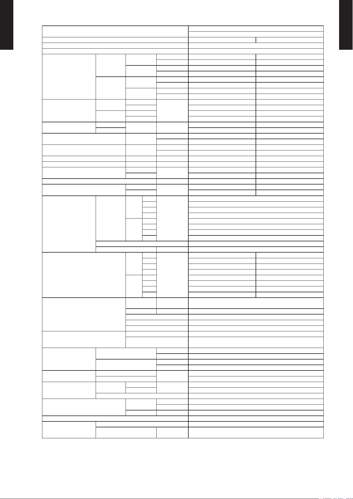
2. DIMENSIONS
MODELS : RIWH09AVFJ, RIWH12AVFJ
WALL MOUNTED TYPE
RIWH09-12AVFJ
Unit: in (mm)
WALL MOUNTED TYPE
RIWH09-12AVFJ
10-5/8 (270)
1-5/16 (34)
[10-5/8 (270)]
8-9/16 (217)
16-3/4 (426)
12-3/16 (310)
Outline of unit
34-1/4 (870)
[34-1/4 (870)]
8-1/16 (204)
17-1/2 (444)
11-5/8 (295)
2-15/16(74)
8-1/4 (209)
2-9/16 (65)
for pipe inlet
6-1/2 (165) 5-11/16 (144)
7 (178) 9-3/16 (233)
12-5/8 (321) 12-3/8 (315)
2-9/16 (65)
for pipe inlet
- (01-02) -
Page 6
WALL MOUNTED TYPE
RIWH09-12AVFJ
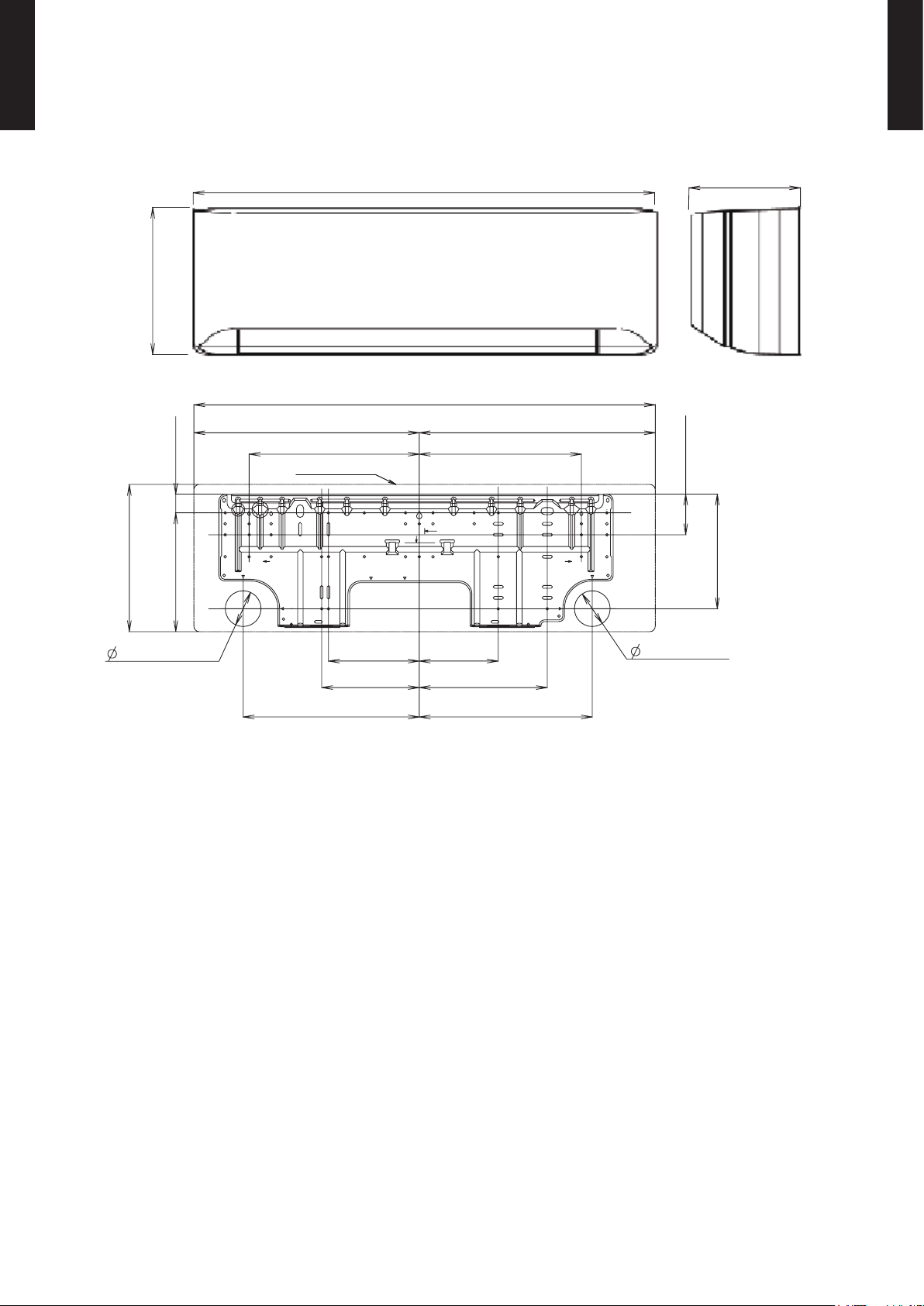
INSTALLATION PLACE
WALL MOUNTED TYPE
RIWH09-12AVFJ
Unit: in (mm)
Outline of unit
1 (25) or more
4 (86) or more
60 (1,500) or more
or more
71 (1,800)
3 (63) or more
2 (45) or more
3 (52) or more
6 (144) or more
- (01-03) -
Page 7
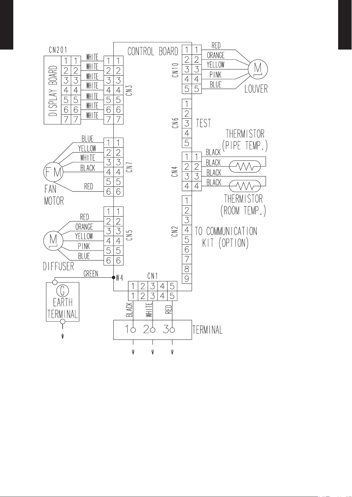
3. WIRING DIAGRAMS
MODELS : RIWH09AVFJ, RIWH12AVFJ
WALL MOUNTED TYPE
RIWH09-12AVFJ
WALL MOUNTED TYPE
RIWH09-12AVFJ
- (01-04) -
Page 8
4. CAPACITY TABLE
4-1. COOLING CAPACITY
WALL MOUNTED TYPE
RIWH09-12AVFJ
MODEL : RIWH09AVFJ
AFR 441
°FDB 64 70 75 80 85 90
°FWB 54 60 63 67 71 73
°FDB TC SHC IP TC SHC IP TC SHC IP TC SHC IP TC SHC IP TC SHC IP
15 8.34 5.55 0.22 9.30 6.19 0.22 10.26 6.82 0.23 10.57 7.04 0.22 11.21 7.46 0.22 11.85 7.89 0.23
23 7.95 5.29 0.24 8.86 5.90 0.24 9.78 6.51 0.25 10.08 6.71 0.24 10.69 7.11 0.25 11.30 7.52 0.25
32 7.57 5.04 0.24 8.43 5.61 0.24 9.31 6.19 0.25 9.59 6.38 0.25 10.17 6.77 0.25 10.74 7.15 0.25
41 7.18 4.78 0.24 8.00 5.32 0.24 8.83 5.88 0.26 9.10 6.06 0.25 9.64 6.42 0.25 10.19 6.78 0.26
50 6.80 4.52 0.22 7.56 5.03 0.22 8.36 5.56 0.23 8.61 5.73 0.23 9.12 6.07 0.23 9.63 6.41 0.24
59 6.41 4.85 0.22 7.13 4.85 0.23 7.88 5.29 0.23 8.12 5.73 0.23 8.60 5.70 0.23 9.08 6.07 0.24
67 8.53 5.29 0.44 9.52 5.32 0.45 10.47 5.80 0.46 10.82 6.28 0.46 11.46 6.24 0.46 12.11 6.65 0.47
77 8.02 5.29 0.51 8.94 5.32 0.52 9.86 5.83 0.52 10.17 6.28 0.53 10.78 6.24 0.53 11.40 6.65 0.54
Outdoor temperature
87 7.54 5.12 0.57 8.39 5.15 0.58 9.25 5.60 0.59 9.52 6.04 0.59 10.10 6.04 0.60 10.68 6.41 0.61
95 7.10 4.98 0.63 7.92 5.02 0.64 8.73 5.46 0.65 9.01 5.90 0.65 9.55 5.87 0.66 10.07 6.24 0.66
104 5.90 4.64 0.51 6.59 4.67 0.52 7.27 5.08 0.53 7.47 5.49 0.53 7.95 5.46 0.54 8.39 5.83 0.54
115 4.20 3.28 0.39 4.67 3.31 0.39 5.12 3.62 0.40 5.29 3.89 0.40 5.60 3.86 0.41 5.94 4.13 0.41
AFR : Air ow rate (CF M)
TC : Total capa city (kB TU)
SHC : Sensible H eat capac ity (kBT U)
IP : Input Power (kW )
AFR 750
°CDB 17.8 21.1 23.9 26.7 29.4 32.2
°CWB 12.2 15.6 17.2 19.4 21.7 22.8
°CDB TC SHC IP TC SHC IP TC SHC IP TC SHC IP TC SHC IP TC SHC IP
-10.0 2.44 1.63 0.22 2.72 1.81 0.22 3.01 2.00 0.23 3.10 2.06 0.22 3.29 2.19 0.22 3.47 2.31 0.23
-5.0 2.33 1.55 0.24 2.60 1.73 0.24 2.87 1.91 0.25 2.96 1.97 0.24 3.13 2.09 0.25 3.31 2.20 0.25
0.0 2.22 1.48 0.24 2.47 1.64 0.24 2.73 1.82 0.25 2.81 1.87 0.25 2.98 1.98 0.25 3.15 2.10 0.25
5.0 2.11 1.40 0.24 2.34 1.56 0.24 2.59 1.72 0.26 2.67 1.78 0.25 2.83 1.88 0.25 2.99 1.99 0.26
10.0 1.99 1.33 0.22 2.22 1.48 0.22 2.45 1.63 0.23 2.52 1.68 0.23 2.67 1.78 0.23 2.82 1.88 0.24
15.0 1.88 1.42 0.22 2.09 1.42 0.23 2.31 1.55 0.23 2.38 1.68 0.23 2.52 1.67 0.23 2.66 1.78 0.24
19.4 2.50 1.55 0.44 2.79 1.56 0.45 3.07 1.70 0.46 3.17 1.84 0.46 3.36 1.83 0.46 3.55 1.95 0.47
25.0 2.35 1.55 0.51 2.62 1.56 0.52 2.89 1.71 0.52 2.98 1.84 0.53 3.16 1.83 0.53 3.34 1.95 0.54
Outdoor temperature
30.6 2.21 1.50 0.57 2.46 1.51 0.58 2.71 1.64 0.59 2.79 1.77 0.59 2.96 1.77 0.60 3.13 1.88 0.61
35.0 2.08 1.46 0.63 2.32 1.47 0.64 2.56 1.60 0.65 2.64 1.73 0.65 2.80 1.72 0.66 2.95 1.83 0.66
40.0 1.73 1.36 0.51 1.93 1.37 0.52 2.13 1.49 0.53 2.19 1.61 0.53 2.33 1.60 0.54 2.46 1.71 0.54
46.1 1.23 0.96 0.39 1.37 0.97 0.39 1.50 1.06 0.40 1.55 1.14 0.40 1.64 1.13 0.41 1.74 1.21 0.41
AFR : Air ow rate (m3/h)
TC : Total capa city (kW )
SHC : Sensible H eat capac ity (kW)
IP : Input Power (kW )
Indoor temperature
Indoor temperature
WALL MOUNTED TYPE
RIWH09-12AVFJ
- (01-05) -
Page 9
WALL MOUNTED TYPE
RIWH09-12AVFJ
MODEL : RIWH12AVFJ
AFR 441
°FDB 64 70 75 80 85 90
°FWB 54 60 63 67 71 73
°FDB TC SHC IP TC SHC IP TC SHC IP TC SHC IP TC SHC IP TC SHC IP
15 11.25 7.76 0.33 12.53 8.65 0.33 13.80 9.53 0.35 14.23 9.82 0.34 15.08 10.41 0.34 15.93 11.00 0.35
23 10.66 7.36 0.37 11.87 8.19 0.38 13.08 9.03 0.40 13.49 9.31 0.39 14.30 9.87 0.39 15.10 10.42 0.40
32 10.07 6.95 0.40 11.21 7.74 0.40 12.36 8.53 0.42 12.74 8.79 0.41 13.51 9.33 0.41 14.27 9.85 0.42
41 9.47 6.54 0.40 10.56 7.29 0.40 11.64 8.04 0.42 12.00 8.28 0.41 12.73 8.78 0.41 13.44 9.27 0.43
50 8.88 6.13 0.39 9.90 6.84 0.39 10.92 7.54 0.41 11.25 7.77 0.40 11.94 8.24 0.40 12.60 8.70 0.41
59 8.29 6.35 0.40 9.25 6.38 0.41 10.20 6.96 0.42 10.51 7.51 0.42 11.16 7.47 0.42 11.77 7.98 0.43
67 11.43 7.47 0.65 12.73 7.51 0.66 14.06 8.19 0.67 14.47 8.84 0.68 15.35 8.80 0.68 16.21 9.38 0.69
77 10.82 7.13 0.75 12.04 7.17 0.76 13.27 7.85 0.77 13.68 8.46 0.77 14.50 8.43 0.78 15.32 8.97 0.79
Outdoor temperature
87 10.10 6.99 0.85 11.26 7.03 0.86 12.39 7.68 0.87 12.80 8.29 0.88 13.55 8.26 0.88 14.30 8.77 0.89
95 9.49 6.69 0.93 10.58 6.72 0.94 11.63 7.34 0.96 12.01 7.92 0.96 12.73 7.88 0.97 13.44 8.39 0.98
104 8.05 6.35 0.87 8.97 6.38 0.89 9.89 6.96 0.90 10.20 7.51 0.91 10.78 7.51 0.92 11.40 7.98 0.92
115 5.66 5.15 0.69 6.28 5.19 0.70 6.93 5.63 0.71 7.17 6.11 0.71 7.57 6.07 0.72 8.02 6.48 0.73
AFR : Air ow rate (CF M)
TC : Total capa city (kB TU)
SHC : Sensible H eat capac ity (kBT U)
IP : Input Power (kW )
AFR 750
°CDB 17.8 21.1 23.9 26.7 29.4 32.2
°CWB 12.2 15.6 17.2 19.4 21.7 22.8
°CDB TC SHC IP TC SHC IP TC SHC IP TC SHC IP TC SHC IP TC SHC IP
-10.0 3.30 2.28 0.33 3.67 2.53 0.33 4.05 2.79 0.35 4.17 2.88 0.34 4.42 3.05 0.34 4.67 3.22 0.35
-5.0 3.12 2.16 0.37 3.48 2.40 0.38 3.83 2.65 0.40 3.95 2.73 0.39 4.19 2.89 0.39 4.43 3.05 0.40
0.0 2.95 2.04 0.40 3.29 2.27 0.40 3.62 2.50 0.42 3.73 2.58 0.41 3.96 2.73 0.41 4.18 2.89 0.42
5.0 2.78 1.92 0.40 3.09 2.14 0.40 3.41 2.36 0.42 3.52 2.43 0.41 3.73 2.57 0.41 3.94 2.72 0.43
10.0 2.60 1.80 0.39 2.90 2.00 0.39 3.20 2.21 0.41 3.30 2.28 0.40 3.50 2.42 0.40 3.69 2.55 0.41
15.0 2.43 1.86 0.40 2.71 1.87 0.41 2.99 2.04 0.42 3.08 2.20 0.42 3.27 2.19 0.42 3.45 2.34 0.43
19.4 3.35 2.19 0.65 3.73 2.20 0.66 4.12 2.40 0.67 4.24 2.59 0.68 4.50 2.58 0.68 4.75 2.75 0.69
25.0 3.17 2.09 0.75 3.53 2.10 0.76 3.89 2.30 0.77 4.01 2.48 0.77 4.25 2.47 0.78 4.49 2.63 0.79
Outdoor temperature
30.6 2.96 2.05 0.85 3.30 2.06 0.86 3.63 2.25 0.87 3.75 2.43 0.88 3.97 2.42 0.88 4.19 2.57 0.89
35.0 2.78 1.96 0.93 3.10 1.97 0.94 3.41 2.15 0.96 3.52 2.32 0.96 3.73 2.31 0.97 3.94 2.46 0.98
40.0 2.36 1.86 0.87 2.63 1.87 0.89 2.90 2.04 0.90 2.99 2.20 0.91 3.16 2.20 0.92 3.34 2.34 0.92
46.1 1.66 1.51 0.69 1.84 1.52 0.70 2.03 1.65 0.71 2.10 1.79 0.71 2.22 1.78 0.72 2.35 1.90 0.73
AFR : Air ow rate (m3/h)
TC : Total capa city (kW )
SHC : Sensible H eat capac ity (kW)
IP : Input Power (kW )
Indoor temperature
Indoor temperature
WALL MOUNTED TYPE
RIWH09-12AVFJ
- (01-06) -
Page 10
4-2. HEATING CAPACITY
WALL MOUNTED TYPE
RIWH09-12AVFJ
MODEL : RIWH09AVFJ
AFR 441
WALL MOUNTED TYPE
RIWH09-12AVFJ
°FDB 60 65 70 75
°FDB °FWB TC IP TC IP TC IP TC IP
5 3 7.1 8 0.68 7.0 1 0.69 6.84 0 .71 6.66 0.72
14 12 8 .13 0 .73 7. 9 4 0.75 7. 74 0.76 7. 5 5 0 .78
23 19 9.1 0 0.76 8.8 8 0.78 8.6 6 0.79 8.45 0.81
32 28 10.48 0.81 10.23 0.83 9.98 0.8 4 9.73 0.8 6
41 37 11.91 0. 86 11.6 3 0.8 8 11 .3 4 0.90 11.0 6 0.92
47 43 12.60 0.85 12.30 0.87 12.00 0.89 11.70 0.91
50 47 12. 26 0.73 11. 97 0.75 11 .6 8 0 .76 11.3 9 0 .78
59 50 12.47 0.72 12.1 8 0 .74 11.8 8 0.75 11. 58 0.77
Outdoor temperature
68 59 12.82 0.67 12. 51 0.68 12 .21 0.70 11. 90 0.71
75 65 13.3 2 0.67 13.0 0 0.68 12 .68 0.6 9 12. 36 0.71
AFR : Air ow ra te (CFM)
TC : Total capa city (kB TU)
IP : Input Power (kW )
AFR 750
°CDB 15.6 18 .3 2 1.1 23.9
°CDB °CWB TC IP TC IP TC IP TC IP
-15 2 .10 2.10 0.68 2.05 0.69 2. 00 0.71 1.9 5 0.72
-10 2.38 2.38 0.73 2.3 3 0.75 2.27 0.76 2.21 0.78
-5 2.67 2 .67 0.76 2. 60 0.78 2.54 0.79 2.48 0.81
0 3.07 3.07 0.81 3.00 0.83 2. 93 0.84 2.85 0.86
5 3.4 9 3.49 0.8 6 3. 41 0.8 8 3.32 0.90 3. 24 0.92
7 3.6 9 3.69 0.8 5 3.61 0.87 3 .52 0.89 3.4 3 0.91
10 3.59 3. 59 0.73 3 .51 0.75 3.42 0 .76 3.34 0.78
15 3.66 3. 66 0.72 3.57 0 .74 3.48 0.75 3. 40 0.77
Outdoor temperature
20 15 3.76 0.67 3.67 0. 68 3.58 0.70 3.49 0 .71
24 18 3.90 0.67 3. 81 0.68 3.72 0.69 3.62 0.71
AFR : Air ow rate (m3/h)
TC : Total capa city (kW )
IP : Input Power (kW )
Indoor temperature
Indoor temperature
MODEL : RIWH12AVFJ
AFR 441
°FDB 60 65 70 75
°FDB °FWB TC IP TC IP TC IP TC IP
5 3 10.71 1.09 10. 46 1.12 10.20 1.1 4 9.95 1 .16
14 12 12.04 1.13 11.7 6 1 .15 11. 47 1.18 11.18 1. 20
23 19 13. 35 1.1 8 13. 03 1.20 12. 71 1.23 12.4 0 1. 25
32 28 1 5.17 1.26 14.80 1.29 14. 44 1.31 14.0 8 1. 34
41 37 16 .13 1.23 15.75 1.25 15.36 1. 28 14.98 1.30
47 43 16.8 0 1. 23 16.40 1.25 16.00 1.28 15.60 1. 31
50 47 1 7. 20 1.23 16.79 1.25 16.38 1. 28 15.97 1. 30
59 50 16.87 1.15 16. 47 1.17 16.07 1.20 15.67 1. 22
Outdoor temperature
68 59 15 .63 0.91 15.25 0.92 14.8 8 0. 94 14.51 0.96
75 65 15.9 4 0.89 15. 56 0.91 15.18 0.93 14. 80 0.95
AFR : Air ow ra te (CFM)
TC : Total capa city (kB TU)
IP : Input Power (kW )
AFR 750
°CDB 15.6 18 .3 2 1.1 23.9
°CDB °CWB TC IP TC IP TC IP TC IP
-15 -16 3.1 4 1.09 3.07 1.12 2.99 1.14 2.92 1 .16
-10 -11 3.5 3 1.1 3 3.45 1.15 3.3 6 1.1 8 3.28 1.20
-5 -7 3 .91 1 .18 3.82 1. 20 3.73 1.2 3 3.63 1. 25
0 -2 4 .44 1.2 6 4.34 1. 29 4.23 1.31 4.1 3 1.34
5 3 4.73 1.2 3 4.62 1. 25 4.5 0 1.28 4. 39 1.3 0
7 6 4.92 1. 23 4. 81 1.2 5 4.69 1. 28 4.5 7 1.31
10 8 5.0 4 1.23 4.92 1. 25 4.80 1.28 4.68 1.30
15 10 4.94 1.15 4.83 1 .17 4.71 1.2 0 4.59 1. 22
Outdoor temperature
20 15 4.58 0.91 4 .47 0.92 4.36 0.94 4.25 0.96
24 18 4.67 0.89 4. 56 0.91 4.45 0.93 4.34 0.9 5
AFR : Air ow rate (m3/h)
TC : Total capa city (kW )
IP : Input Power (kW )
Indoor temperature
Indoor temperature
- (01-07) -
Page 11
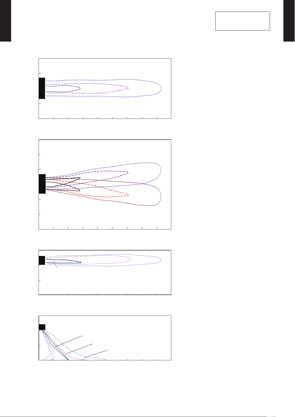
5. FAN PERFORMANCE
7 (2)
3 (1) 2 (0.5)
7 (2)
3 (1)
2 (0.5)
5-1. AIR VELOCITY DISTRIBUTION
WALL MOUNTED TYPE
RIWH09-12AVFJ
MODELS : RIWH09AVFJ, RIWH12AVFJ
(m)
(f t.)
2
7
1
3
0
0
1
3
2
7
0 1 2 3 4 5 6 7 8 9
0 3 7 10 13 16 20 23 26 30
(m)
(f t.)
10
3
7
2
Unit : ft./s (m/s)
Unit : ft./s (m/s)
TOP VIEW
Vertic al air ow direct ion louve r: Up
Horizo ntal air ow dire ction lou ver: Cent er
(m)
(f t.)
TOP VIEW
Vertic al air ow direct ion louve r: Up
Horizo ntal air ow dire ction lou ver: Righ t & Left
Conditions:
Fan speed: HIGH
Operation mode: FAN
WALL MOUNTED TYPE
RIWH09-12AVFJ
3
1
3 (1)
0
3
7
10
(f t.)
10
7
3
0
(f t.)
10
7
7 (2)
0
3 (1)
1
2
3
0 1 2 3 4 5 6 7 8 9
0 3 7 10 13 16 20 23 26 30
(m)
3
3 (1)
2
7 (2)
1
0
0 1 2 3 4 5 6 7 8 9
0 3 7 10 13 16 20 23 26 30
(m)
3
2
2 (0.5)
2 (0.5)
Unit : ft./s (m/s)
Unit : ft./s (m/s)
2 (0.5)
(m)
(f t.)
SIDE VI EW
Vertic al air ow direct ion louve r: Up
Horizo ntal air ow dire ction lou ver: Cent er
(m)
(f t.)
SIDE VI EW
Vertic al air ow direct ion louve r: Down
Horizo ntal air ow dire ction lou ver: Cent er
3
1
0
0
0 1 2 3 4 5 6 7 8 9
0 3 7 10 13 16 20 23 26 30
- (01-08) -
(m)
(f t.)
Page 12
5-2. AIR FLOW
WALL MOUNTED TYPE
RIWH09-12AVFJ
MODELS : RIWH09AVFJ, RIWH12AVFJ
Cooling
z
Number of
Fan speed
rotations
Air ow
(r.p.m.)
3
m
/h 750
WALL MOUNTED TYPE
RIWH09-12AVFJ
HIGH 1320
MED 116 0
LOW 930
QUIET 680
Heating
z
Fan speed
Number of
rotations
(r.p.m.)
l/s 208
CFM 4 41
3
/h 640
m
l/s 178
CFM 376
3
/h 480
m
l/s 133
CFM 282
3
/h 310
m
l/s 86
CFM
182
Air ow
3
m
/h 750
HIGH 1320
MED 116 0
LOW 980
QUIET 710
l/s 208
CFM 4 41
3
/h 640
m
l/s 178
CFM 376
3
/h 520
m
l/s 144
CFM 306
3
/h 330
m
l/s 92
CFM
194
- (01-09) -
Page 13
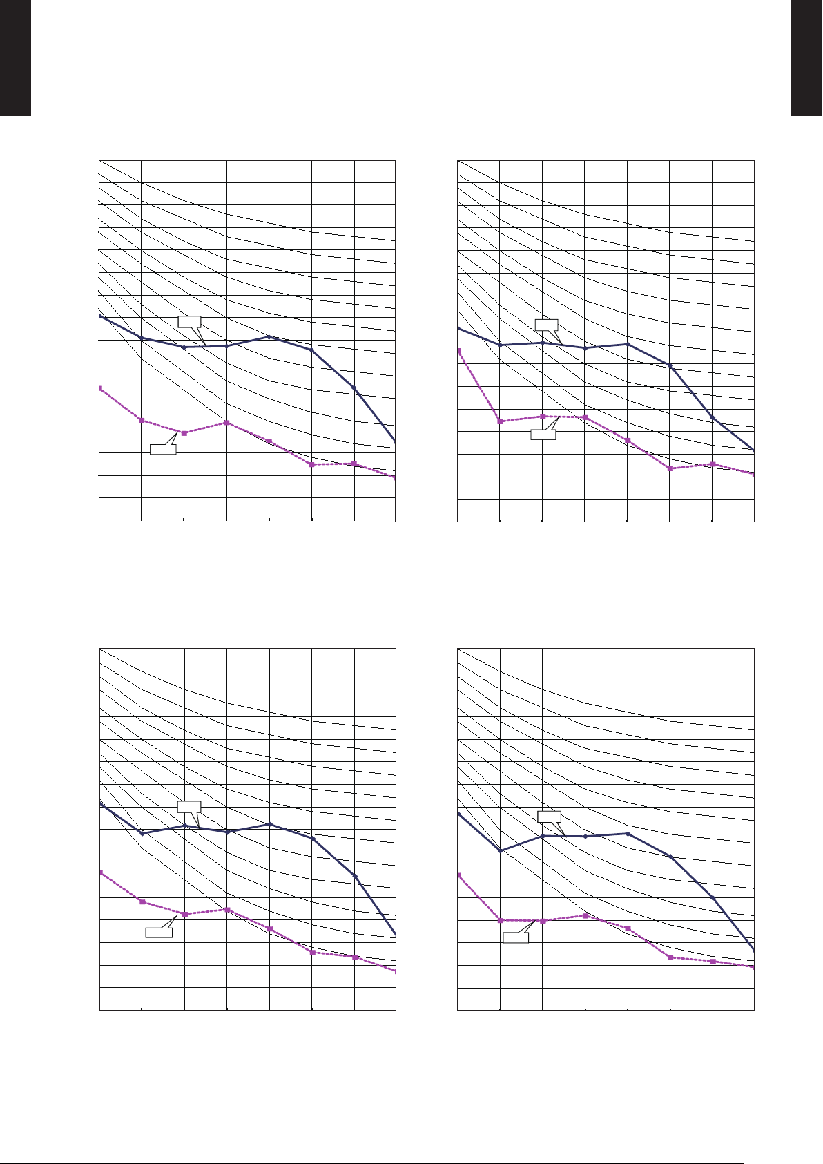
6. OPERATION NOISE (SOUND PRESSURE)
Quiet
6-1. NOISE LEVEL CURVE
WALL MOUNTED TYPE
RIWH09-12AVFJ
MODEL : RIWH09AVFJ
WALL MOUNTED TYPE
RIWH09-12AVFJ
Cooling
z
80
80
70
70
60
60
50
50
High
40
40
30
30
20
20
Octave band sou nd pressure level, dB: (0 dB=0.0002 µba r)
10
10
0
0
63 125 250 500 1,000 2,000 4,000 8,000
63 125 250 500 1,000 2,000 4,000 8,000
Quiet
Octave band cente r frequency,Hz
Octave band cente r frequency,Hz
NC-65
NC-60
NC-55
NC-50
NC-45
NC-40
NC-35
NC-30
NC-25
NC-20
NC -15
Heating
z
80
80
70
70
60
60
50
50
High
40
40
30
30
20
20
Octave band sou nd pressure level, dB: (0 dB=0.0002 µba r)
10
10
0
0
63 125 250 500 1,000 2,000 4,000 8,000
63 125 250 500 1,000 2,000 4,000 8,000
Quiet
Octave band cente r frequency,Hz
Octave band cente r frequency,Hz
NC-65
NC-60
NC-55
NC-50
NC-45
NC-40
NC-35
NC-30
NC-25
NC-20
NC -15
MODEL : RIWH12AVFJ
Cooling
z
80
70
60
50
High
40
30
20
Octave band sou nd pressure level, dB: (0 dB=0.0002 µba r)
10
NC-65
NC-60
NC-55
NC-50
NC-45
NC-40
NC-35
NC-30
NC-25
NC-20
NC -15
Heating
z
80
70
60
50
40
30
20
Octave band sou nd pressure level, dB: (0 dB=0.0002 µba r)
10
Quiet
High
NC-65
NC-60
NC-55
NC-50
NC-45
NC-40
NC-35
NC-30
NC-25
NC-20
NC -15
0
63 125 250 500 1,000 2,000 4,000 8,000
Octave band cente r frequency,Hz
- (01-10) -
0
63 125 250 500 1,000 2,000 4,000 8,000
Octave band cente r frequency,Hz
Page 14
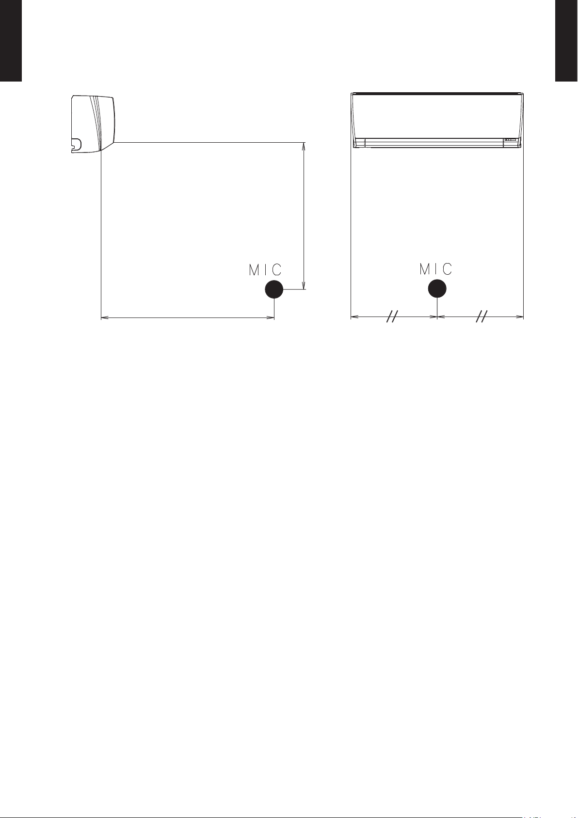
6-2. SOUND LEVEL CHECK POINT
WALL MOUNTED TYPE
RIWH09-12AVFJ
32in. (0.8m)
40in. (1m)
WALL MOUNTED TYPE
RIWH09-12AVFJ
- (01-11) -
Page 15

7. ELECTRICAL CHARACTERISTICS
WALL MOUNTED TYPE
RIWH09-12AVFJ
Model name RIWH 09AV FJ RI WH12AVFJ
Power supply
Max. operating current A 0.4
Wiring spec. *1
1*: Wiring specication
Selected sample
(Selected based on Japan Electrotechnical Standards and Codes Committee E0005)
Volt age V 208 / 230 ~
Frequency Hz 60
Connection cable AWG 14
Limited wiring length ft.(m) 68 (21)
WALL MOUNTED TYPE
RIWH09-12AVFJ
- (01-12) -
Page 16

8. SAFETY DEVICES
WALL MOUNTED TYPE
RIWH09-12AVFJ
Protection form
Circuit protection Current fuse (PC board) 250V 3.15A
Fan motor protection Thermal protector program
OFF: 221 ± 18 °F (105 ± 10 °C)
ON: 194 ± 18 °F (90 ± 10 °C)
Model
RIWH 09AV FJ
RIWH12AV FJ
WALL MOUNTED TYPE
RIWH09-12AVFJ
- (01-13) -
Page 17

9. EXTERNAL INPUT & OUTPUT
Operation
Stop
ON
OFF
Input signal
Indoor unit
Connector INPUT OUTPUT REMARKS
WALL MOUNTED TYPE
RIWH09-12AVFJ
CNA01 Control input CNB01 - Operation status output
CNB02 - Error status output
See external
input/output settings
for details.
WALL MOUNTED TYPE
RIWH09-12AVFJ
9-1. EXTERNAL INPUT
CONTROL INPUT (Operation/Stop or Forced stop)
The air conditioner can be remotely operated by means of the following on-site work.
"Operation/Stop" mode or "Forced stop" mode can be selected with function setting of indoor unit.
Unit operation is started at the following contents by adding the contact input of a commercial ON/OFF switch to a
connector on the external control PC board and turning it ON.
Unit operation Initial setting after power is ON Starting mode other than initial setting
Operation mode Auto changeover Mode at previous operation
Set temperature 75°F (24°C) Temperature at previous operation
Air ow mode AUTO Mode at previous operation
Air direction (swing) Standard air direction (swing OFF) Air direction at previous operation
Circuit diagram example
z
Indoor unit
control PC board Communication kit
Connected unit
Connector
1
3
Optional parts
* Make the distance from the PC board to the connected unit within 33ft. (10m).
Contact capacity: DC 24 V or more, 10 mA or more.
Use non-polar relays and switches.
When function setting is in "Operation/Stop" mode
z
Ex.) Switch
*33ft. (10m)
Signal
Locally purchased
- (01-14) -
Page 18

WALL MOUNTED TYPE
Remote controller
ON ON ON
Input signal
ON
OFF
Indoor unit
Operation
Stop
Command
Forced stop
Normal
Remote control
operation invalidity
RIWH09-12AVFJ
When function setting is in "Forced stop" mode
z
Parts (Optional)
z
WALL MOUNTED TYPE
RIWH09-12AVFJ
Parts name
Model name
External connect kit RXXWZXZ5
Communication kit RXXCBXZ2
* For operating the EXTERNAL function, the wall mounted type requires the communication kit in addition to the wire
(RX XWZXZ5).
Wire (External input) : RXXWZXZ5
- (01-15) -
Page 19

9-2. EXTERNAL OUTPUT
Indoor unit
Optional parts Locally purchased
Indoor unit
Output signal
WALL MOUNTED TYPE
RIWH09-12AVFJ
OPERATION STATUS OUTPUT
An air conditioner operation status signal can be output.
Circuit diagram example
z
control PC board Communication kit Connected unit
WALL MOUNTED TYPE
RIWH09-12AVFJ
Operation
Stop
ON
OFF
Connector
1
2
24V DC
V
*33ft.
(10m)
*: Make the distance from the PC board to the connected unit within 33ft. (10m)
Relay spec.: Max. DC 24 V, 10 mA to less than 500 mA.
Ex.)Relay unit
Signal
Ex.)Display
Relay
power
supply
Parts (Optional)
z
Parts name
Model name
External connect kit RXXWZXZ5
Communication kit RXXCBXZ2
* For operating the EXTERNAL function, the wall mounted type requires the communication kit in addition to the wire
(RX XWZXZ5).
Wire (External output) : RXXWZXZ5
- (01-16) -
Page 20

WALL MOUNTED TYPE
Indoor unit
Optional parts Locally purchased
Error status
Output signal
RIWH09-12AVFJ
ERROR STATUS OUTPUT
WALL MOUNTED TYPE
RIWH09-12AVFJ
An air conditioner error status signal can be output.
Circuit diagram example
z
control PC board Communication kit Connected unit
Error
Normal
Parts (Optional)
z
Parts name
Connector
1
2
ON
OFF
24V DC
V
*33ft.
(10m)
*: Make the distance from the PC board to the connected unit within 33ft. (10m)
Relay spec.: Max. DC 24 V, 10 mA to less than 500 mA.
Model name
External connect kit RXXWZXZ5
Communication kit RXXCBXZ2
Ex.)Relay unit
Signal
Ex.)Display
Relay
power
supply
* For operating the EXTERNAL function, the wall mounted type requires the communication kit in addition to the wire
(RX XWZXZ5).
Wire (External output) : RXXWZXZ5
- (01-17) -
Page 21

REG1U
10. WIRELESS REMOTE CONTROLLER
FUNCTIONS
WALL MOUNTED TYPE
RIWH09-12AVFJ
Signal
transmitter
WALL MOUNTED TYPE
RIWH09-12AVFJ
MIN. HEAT
button
TEMP.
button
POWERFUL
button
Start/Stop
button
MODE button
ECONOMY button
FAN button
SWING button
SET button
TIMER ON button
TIMER OFF button
REG1U
TIMER SELECT button
RESET button
°C / °F switching button
TIMER SLEEP button
CLOCK ADJUST button
TIMER CANCEL button
Display panel
Mode indicator
Send indicator
To facilitate explanation, the accompanying illustration has been drawn to show all possible indicators; in actual operation,
however, the display will only show those indicators appropriate to the current operation.
Temperature indicator
Transmit indicator
Fan Speed indicator
Swing indicator
Clock & Timer
indicator
SPECIFICATION
DIMENSIONS [H × W × D]: in. (mm) 8-1/16 (205) × 2-3/8 (61) × 11/16 (17)
WEIGHT oz. (g) 4.3 (12 2)
ACCESSORY Holder
- (01-18) -
NOTE: Some button operations may
not be available for all units
or systems.
For details, refer to the
operation manual.
Page 22

11. FUNCTION SETTINGS
value
11-1. INDOOR UNIT (Setting by remote controller)
WALL MOUNTED TYPE
RIWH09-12AVFJ
• The function settings of the control of the indoor unit can be changed by this procedure according
to the installation conditions. Incorrect settings can cause the indoor unit to malfunction.
• After the power is turned on, perform the Function Setting according to the installation conditions
using the remote controller.
• The settings may be selected between the following two: Function Number and Setting Value.
• Settings will not be changed if invalid numbers or setting values are selected.
PREPARATION
• Before turning on the power of the indoor unit:
- Conrm whether the piping air-tight test and vacuuming have been conducted.
- Reconrm whether there is no miswiring.
• Turn on the power of the indoor units.
FUNCTION SETTING METHOD (for Wireless remote controller)
Entering the Function Setting Mode
While pressing the POWERFUL button and SET TEMP. ( ) simultaneously, press the RESET button to enter the
•
function setting mode.
STEP 1
Setting the Remote controller Custom code
Use the following steps to select the custom code of the remote controller. (Note that
the air conditioner cannot receive a signal code if the air conditioner has not been set
for the matching custom code.) The custom codes that are set through this process
are applicable only during the Function Setting process. For details on how to set
the custom codes through the normal process, refer to "REMOTE CONTROLLER
CUSTOM CODE SETTING".
1. Press the SET TEMP. ( ) ( ) button to change the custom code between →
→ → .
Match the code on the display to the air conditioner custom code. (initially set to )
(If the custom code does not need to be selected, press the MIN. HEAT button and
proceed to
2. Press the MODE button and check that the indoor unit can receive signals at the
displayed custom code.
3. Press the MIN. HEAT button to accept the custom code, and proceed to
STEP 2
.)
STEP 2
.
WALL MOUNTED TYPE
RIWH09-12AVFJ
The air conditioner custom code is set to "A" prior to shipment.
The remote controller resets to custom code A when the batteries in the remote controller are replaced. If you use a
custom code other than custom code A, reset the custom code after replacing the batteries.
If you do not know the air conditioner custom code setting, try each of the custom codes ( → → → ) until
you nd the code which operates the air conditioner.
STEP 2
Selecting the Function Number and Setting Value
1. Press the SET TEMP. ( ) ( ) buttons to select the function number.
(Press the MIN. HEAT button to switch between the left and right
digits.)
2. Press the POWERFUL button to proceed to setting the value.
(Press the POWERFUL button again to return to the function number
selection.)
3. Press the SET TEMP. ( ) ( ) buttons to select the setting value.
(Press the MIN. HEAT button to switch between the left and right
digits.)
4. Press the MODE button, then the START/STOP button in order to x
the settings.
5. Press the RESET button to end the function setting mode.
6. After completing the Function Setting, be sure to turn off the power
and turn it on again.
CAUTION
After turning off the power, wait 30 seconds or more before turning on it again.
The Function Setting will not become active unless the power is turned off then on again.
Function number
Setting
- (01-19) -
Page 23

FUNCTION DETAILS
WALL MOUNTED TYPE
RIWH09-12AVFJ
1) Filter sign
2) Room temperature control for indoor unit sensor
3) Auto restart
4) Room temperature sensor switching
5) Remote controller custom code
6) External input control
7) Room temperature sensor switching (Aux.)
8) Indoor unit fan control for energy saving for cooling
9) Room temperature control for wired remote controller sensor
10) Heat Insulation condition (building insulation)
Functions
WALL MOUNTED TYPE
RIWH09-12AVFJ
1) Filter sign
Select appropriate intervals for displaying the lter sign on the indoor unit according to the
estimated amount of dust in the air of the room.
If the indication is not required, select "No indication" (03).
(... Factory setting)
Function number Setting value Setting description
00 Standard (400 hours)
11
01 Long interval (1000 hours)
02 Short interval (200 hours)
03 No indication
2) Room temperature control for indoor unit sensor
Refer to Function 95, before performing this setting.
Depending on the installed environment, correction of the room temperature sensor may be
required. Select the appropriate control setting according to the installed environment.
The temperature correction values show the difference from the Standard setting "00"
(manufacturer's recommended value).
* When Function 95-01(High insulation) is set, the Standard setting "00" will be the same as No
correction "01" [0.0°F (0.0°C)].
(... Factory setting)
Function number Setting value Setting description
More Cooling
Less Heating
Less Cooling
More Heating
30
(For cooling)
31
(For heating)
00 Standard setting*
01 No correction 0.0°F (0.0°C)
02 -1°F (-0.5°C)
03 -2°F (-1.0°C)
04 -3°F (-1.5°C)
05 -4°F (-2.0°C)
06 -5°F (-2.5°C)
07 -6°F (-3.0°C)
08 -7°F (-3.5°C)
09 -8°F (-4.0°C)
10 +1°F (+0.5°C)
11 +2°F (+1.0°C)
12 +3°F (+1.5°C)
13 +4°F (+2.0°C)
14 +5°F (+2.5°C)
15 +6°F (+3.0°C)
16 +7°F (+3.5°C)
17 +8°F (+4.0°C)
- (01-20) -
Page 24

WALL MOUNTED TYPE
RIWH09-12AVFJ
3) Auto restart
WALL MOUNTED TYPE
RIWH09-12AVFJ
Enable or disable automatic restart after a power interruption.
(... Factory setting)
Function number Setting value Setting description
40
00 Enable
01 Disable
* Auto restart is an emergency function such as for power outage etc.
Do not attempt to use this function in normal operation.
Be sure to operate the unit by remote controller or external device.
4) Room temperature sensor switching
(Only for Wired remote controller)
When using the Wired remote controller temperature sensor, change the setting to "Both" (01).
(... Factory setting)
Function number Setting value Setting description
42
00 Indoor unit
01 Both
00: Sensor on the indoor unit is active.
01: Sensors on both indoor unit and wired remote controller are active.
*Remote controller sensor must be turned on by using the remote controller.
5) Remote controller custom code
(Only for wireless remote controller)
The indoor unit custom code can be changed.
Select the appropriate custom code.
(... Factory setting)
Function number Setting value Setting description
44
00 A
01 B
02 C
03 D
6) External input control
"Operation/Stop" mode or "Forced stop" mode can be selected.
(... Factory setting)
Function number Setting value Setting description
46
00 Operation/Stop mode
01 (Setting prohibited)
02 Forced stop mode
7) Room temperature sensor switching (Aux.)
To use the temperature sensor on the wired remote controller only, change the setting to
"Wired remote controller" (01). This function will only work if the function setting 42 is set at
"Both" (01)
(... Factory setting)
Function number Setting value Setting description
48
00 Both
01 Wired remote controller
- (01-21) -
Page 25

8) Indoor unit fan control for energy saving for cooling
WALL MOUNTED TYPE
RIWH09-12AVFJ
Enables or disables the power-saving function by controlling the indoor unit fan rotation when
WALL MOUNTED TYPE
RIWH09-12AVFJ
the outdoor unit is stopped during cooling operation.
(... Factory setting)
Function number Setting value Setting description
49
00 Disable
01 Enable
*00: When the outdoor unit is stopped, the indoor unit fan operates continuously following
the setting on the remote controller..
*01: When the outdoor unit is stopped, the indoor unit fan operates intermittently at a very
low speed.
9) Room temperature control for wired remote controller sensor
Refer to Function 95, before performing this setting.
Depending on the installed environment, correction of the wired remote controller temperature
sensor may be required. Select the appropriate control setting according to the installed
environment.
To change this setting, set Function 42 to Both "01".
Ensure that the Thermo Sensor icon is displayed on the remote controller screen.
(... Factory setting)
Function number Setting value Setting description
More Cooling
Less Heating
Less Cooling
More Heating
92
(For cooling)
93
(For heating)
00 No correction 0.0°F(0.0°C)
01 No correction 0.0°F (0.0°C)
02 -1°F (-0.5°C)
03 -2°F (-1.0°C)
04 -3°F (-1.5°C)
05 -4°F (-2.0°C)
06 -5°F (-2.5°C)
07 -6°F (-3.0°C)
08 -7°F (-3.5°C)
09 -8°F (-4.0°C)
10 +1°F (+0.5°C)
11 +2°F (+1.0°C)
12 +3°F (+1.5°C)
13 +4°F (+2.0°C)
14 +5°F (+2.5°C)
15 +6°F (+3.0°C)
16 +7°F (+3.5°C)
17 +8°F (+4.0°C)
10) Heat Insulation condition (building insulation)
Heat insulation conditions differ according to the installed environment.
Standard insulation "00" allows system to rapidly respond to the cooling or heating load
changes. High insulation "01" is when the heat insulation structure of the building is high and
does not require system to rapidly respond to cooling or heating load changes.
When High insulation "01" is selected;
Overheating (overcooling) is prevented at the start-up.
All room temp. control settings (Function 30, 31, 92, 93) will reset to No correction [0.0°F
(0.0°C)].
(... Factory setting)
Function number Setting value Setting description
95
NOTE:
When changing Function 95, perform this setting before other Room temp. control settings (Function 30, 31, 92,
93). If Funtion 95 is not set rst, Room temperature control settings (Function 30, 31, 92, 93) will be reset and you
must re-do them again.
00 Standard insulation
01 High insulation
- (01-22) -
Page 26

WALL MOUNTED TYPE
RIWH09-12AVFJ
REMOTE CONTROLLER CUSTOM CODE SETTING
Use the following steps to select the custom code of the remote controller.
(Note that the air conditioner cannot receive a signal if the air conditioner has not
been set for the matching custom code.)
1. Press the START/STOP button until only the clock is displayed on the remote
controller display.
2. Press the MODE button for at least ve seconds to display the current custom
code (initially set to ).
3. Press the SET TEMP. ( ) ( ) button to change the custom code between →
→ → .
Match the code on the display to the air conditioner custom code.
4. Press the MODE button again to return to the clock display. The custom code will
be changed.
If no buttons are pressed within 30 seconds after the custom code is displayed, the system returns to the original
clock display. In this case, start again from step 1.
The air conditioner custom code is set to A prior to shipment.
The remote controller resets to custom code A when the batteries in the remote controller are replaced. If you use a
custom code other than custom code A, reset the custom code after replacing the batteries. If you do not know the
air conditioner custom code setting, try each of the custom codes ( → → → ) until you nd the code which
operates the air conditioner.
WALL MOUNTED TYPE
RIWH09-12AVFJ
REMOTE CONTROLLER TEMPERATURE UNIT
To change the temperature unit:
• Press the °C / °F switching button to select the preferred temperature unit. (Factory setting is °F.)
- (01-23) -
Page 27

12. OPTIONAL PARTS
12-1. CONTROLLERS
WALL MOUNTED TYPE
RIWH09-12AVFJ
Exterior Parts name Model No. Summary
WALL MOUNTED TYPE
RIWH09-12AVFJ
Monitor
Mo
10:00
Set temp.
80
Icon check:
AM
Fan
°
F
High
Wired remote
controller
RXRVNUM
Mode
Cool
Menu
Large and full-dot liquid crystal
screen, wide and large keys
easy to press, user-intuitive
ar row key.
*Optional communication kit
is necessary for installation.
The room temperature can
be controlled by detecting the
Wired remote
controller
RXRNNUM
temperature accurately with
built-in thermo sensor.
*Optional communication kit
is necessary for installation.
Compact remote controller
concentrates on the basic
Simple remote
controller
RXRSNUM
functions such as Start/Stop,
Fan Control, Temperature
Setting and Operation mode.
*Optional communication kit
is necessary for installation.
12-2. OTHERS
Exterior Parts name Model No. Summary
(X1)
(X 2)
Communication
kit
External
connect kit
RXXCBXZ2
RXXWZXZ5
Use to connect with optional
devices and air conditioner
PC board.
Required when external device
is connected.
*Optional communication kit
is necessary for installation.
- (01-24) -
Page 28

2. OUTDOOR UNIT
SINGLE TYPE :
ROSH09AFWJ
ROSH12AFWJ
DTR_AO230E_01
2017.01.27
Page 29

2. OUTDOOR UNIT
CONTENTS
1. SPECIFICATIONS
OUTDOOR UNIT
ROSH09-12AFWJ
2. DIMENSIONS
3. REFRIGERANT CIRCUIT
4. WIRING DIAGRAMS
.............................................................................................. 02 - 01
........................................................................................................ 02 - 02
............................................................................ 02 - 04
........................................................................................ 02 - 06
OUTDOOR UNIT
ROSH09-12AFWJ
5. CAPACITY COMPENSATION RATE FOR PIPE LENGTH
AND HEIGHT DIFFERENCE
6. ADDITIONAL CHARGE CALCULATION
7. AIR FLOW
8. OPERATION NOISE
8-1. NOISE LEVEL CURVE (SOUND PRESSURE)
8-2. SOUND LEVEL CHECK POINT
.................................................................................................................02 - 11
......................................................................................... 02 - 12
..................................................................... 02 - 08
......................................... 02 - 10
............................................ 02 - 12
..................................................................... 02 - 13
9. ELECTRIC CHARACTERISTICS
10. SAFETY DEVICES
............................................................................................ 02 - 15
........................................................... 02 - 14
Page 30

1. SPECIFICATIONS
Type INVERTER HEAT PUMP
Model name ROSH09AFWJ ROSH12AFWJ
Power sourse 208/230V~60HZ
Available voltage range 187-253V~60HZ
Starting current A 4.2 5.9
Airow rate
Fan
OUTDOOR UNIT
ROSH09-12AFWJ
Sound pressure level
Heat exchanger type
Compressor
Refrigerant
Refrigerant oil Type RB68 VG74
Enclosure
Dimensions
(H×W×D)
Weight
Connenction
pipe
Operation range
Type×Q'ty Propeller fan×1
Motor output W 23 37
Type×Q'ty Rotary×1
Motor output W 500 750
Net
Gross
Net
Gross 67(30) 86(39)
Size
Method Flare
Pre - charge length
Min. length 9(3)
Max.length 66(20)
Max.height difference 49(15)
Cooling
Heating 906(1540) 889(1510)
Cooling
Heating 48 49
Dimensions
(H×W×D)
Fin pitch FPI 18
Rows×Stages 2×24
Pipe type Copper
Fin Type Aluminum
Type R410A
Charge
Material Steel
Color
Liquid
Gas Ø3/8(Ø9.52)
Cooling
Heating 5 to 75(-15to 24)
CFM
(m3/h)
dB(A)
in. 19-13/16×25-1/4×1-7/16 19-13/16×35-1/4×1-7/16
mm 504×642×36.4 504×896×36.4
lb.oz. 1lb.14oz. 2lb.5oz.
kg 0.85 1.05
mm 540×660×290 540×790×290
in. 21-1/4×26×11-7/16 21-1/4×31-1/8×11-7/16
mm 611×797×401 648×934×400
in. 24-1/16×31-3/8×15-13/16 25-1/2×36-3/4×15-3/4
lb.(kg)
in.
(mm)
ft.
(m)
°F
(°C)
995(1690) 1036(1760)
48 49
Beige
Approximate color of MUNSELL 10YR7.5/1.0
60(27) 80(36)
Ø1/4(Ø6.35)
49(15)
14to115(-10 to 46)
OUTDOOR UNIT
ROSH09-12AFWJ
Note:
Specications are based on the following conditions.
Cooling:Indoor temperature of 80°F(26.67°C)DB/67°F(19.44°C)WB,and outdoor temperature of 95°F(35°C)DB/75°F(23.9°C)WB.
Heating:Indoor temperature of 70°F(21.11°C)DB/59°F(15°C)WB,and outdoor temperature of 47°F(8.33°C)DB/43°F(6.11°C)WB.
Pipe length:24ft.(7.5m),Height difference:0ft. (0m)(Outdoor unit-Indoor unit)
- (02 - 01) -
Page 31

2. DIMENSIONS
MODEL : ROSH09AFWJ
Unit : in.(mm)
OUTDOOR UNIT
ROSH09-12AFWJ
OUTDOOR UNIT
ROSH09-12AFWJ
13/16 (20)
21-1/4 (5 40)
12-1/2 (318)
26 (660)
13-16 (20)
3/8 (9)
17-7/8 (4 54)
2-11/16 (68) 11/16 (18)3/8 (10) 11-7/16 (290)
13-7/8 (352)
6-7/8 (175)
5-5/16 (13 5)
INSTALLATION PLACE
24 (600) or more
4 (100) or more
10 (250) or more
(Service space)
8 (200) or more
4 (100) or more
• Height above the oor level should be 2 in. (50 mm) or more.
• To obtain better operation efciency, when the outdoor unit
is installed, be sure to open the front and left side.
4- 5/16 (110)
Unit : in.(mm)
CAUTION
When the outdoor temperature is 32 °F
•
(0 °C ) or less, do not use the accessory
drain pipe and drain cap. If the drain pipe
and drain cap are used, the drain water in
the pipe may freeze in extremely cold
weather. (Reverse cycle model only)
In areas with heavy snowfall, if the intake
•
and outlet of outdoor unit is blocked with
snow, it might become difficult to get warm
and it is likely to cause breakdown.
Please construct a canopy and a pedestal or
place the unit on a high stand (local
configured).
- (02 - 02) -
Page 32

MODEL : ROSH12AFWJ
Unit : in.(mm)
OUTDOOR UNIT
ROSH09-12AFWJ
OUTDOOR UNIT
ROSH09-12AFWJ
13/16 (20)
21-1/4 (5 40)
12-1/2 (318)
31-1/8 (79 0)
13-16 (20)
3/8 (9)
21-1/4 (5 40)
2-11/16 (68) 11/16 (18)3/8 (10) 11-7/16 (29 0)
13-7/8 (352)
6-7/8 (175)
8-1/4 (20 9)
4- 5/16 (110)
INSTALLATION PLACE
24 (600) or more
4 (100) or more
10 (250) or more
(Service space)
8 (200) or more
4 (100) or more
• Height above the oor level should be 2 in. (50 mm) or more.
• To obtain better operation efciency, when the outdoor unit
is installed, be sure to open the front and left side.
Unit : in.(mm)
CAUTION
When the outdoor temperature is 32 °F
•
(0 °C ) or less, do not use the accessory
drain pipe and drain cap. If the drain pipe
and drain cap are used, the drain water in
the pipe may freeze in extremely cold
weather. (Reverse cycle model only)
In areas with heavy snowfall, if the intake
•
and outlet of outdoor unit is blocked with
snow, it might become difficult to get warm
and it is likely to cause breakdown.
Please construct a canopy and a pedestal or
place the unit on a high stand (local
configured).
- (02 - 03) -
Page 33

3. REFRIGERANT CIRCUIT
MODEL : ROSH09AFWJ
OUTDOOR UNIT
ROSH09-12AFWJ
OUTDOOR UNIT
ROSH09-12AFWJ
- (02 - 04) -
Page 34

MODEL : ROSH12AFWJ
OUTDOOR UNIT
ROSH09-12AFWJ
OUTDOOR UNIT
ROSH09-12AFWJ
- (02 - 05) -
Page 35

4. WIRING DIAGRAMS
MODEL : ROSH09AFWJ
OUTDOOR UNIT
ROSH09-12AFWJ
OUTDOOR UNIT
ROSH09-12AFWJ
- (02 - 06) -
Page 36

MODEL : ROSH12AFWJ
OUTDOOR UNIT
ROSH09-12AFWJ
OUTDOOR UNIT
ROSH09-12AFWJ
- (02 - 07) -
Page 37

5. CAPACITY COMPENSATION RATE FOR PIPE LENGTH AND HEIGHT DIFFERENCE
MODEL : ROSH09AFWJ
Pipe length
COOLING
Ú
OUTDOOR UNIT
ROSH09-12AFWJ
Indoor unit is higher
than outdoor unit.
Height
difference H
Indoor unit is lower
than outdoor unit
Indoor unit is higher
than outdoor unit.
Height
difference H
Indoor unit is lower
than outdoor unit
1
Ú
2
HEATING
Ú
1
Ú
2
15m 49ft. - - - 0.872 0.910
10m 33ft. - - 0.961 0.886 0.925
7.5m 25ft. - 0.979 0.965 0.890 0.929
5m 16ft. 0.992 0.983 0.969 0.893 0.933
0m 0ft. 1.000 0.991 0.976 0.901 0.940
-5m -16ft. 1.000 0.991 0.976 0.901 0.940
-7.5m -25ft. - 0.991 0.976 0.901 0.940
-10m -33ft. - - 0.976 0.901 0.940
-15m -49ft. - - - 0.901 0.940
15m 49ft. - - - 0.832 0.822
10m 33ft. - - 0.917 0.832 0.822
7.5m 25ft. - 0.961 0.917 0.832 0.822
5m 16ft. 1.000 0.961 0.917 0.832 0.822
0m 0ft. 1.000 0.961 0.917 0.832 0.822
-5m -16ft. 0.995 0.956 0.912 0.828 0.818
-7.5m -25ft. - 0.954 0.910 0.826 0.816
-10m -33ft. - - 0.908 0.824 0.814
-15m -49ft. - - - 0.815 0.805
5m 7.5m 10m 15m 20m
16ft. 25ft. 33ft. 49ft. 66ft.
Pipe length
5m 7.5m 10m 15m 20m
16ft. 25ft. 33ft. 49ft. 66ft.
OUTDOOR UNIT
ROSH09-12AFWJ
Height difference H
Indoor unit
H H
Outdoor unit
Connection pipe
1 Indoor unit is higher than outdoor unit.
Outdoor unit
Indoor unit
Connection pipe
2 Indoor unit is lower than outdoor unit.
- (02 - 08) -
Page 38

MODEL : ROSH12AFWJ
Pipe length
COOLING
Ú
OUTDOOR UNIT
ROSH09-12AFWJ
Indoor unit is higher
than outdoor unit.
Height
difference H
Indoor unit is lower
than outdoor unit
Indoor unit is higher
than outdoor unit.
Height
difference H
Indoor unit is lower
than outdoor unit
1
Ú
2
HEATING
Ú
1
Ú
2
15m 49ft. - - - 0.858 0.868
10m 33ft. - - 0.929 0.872 0.882
7.5m 25ft. - 0.960 0.933 0.876 0.885
5m 16ft. 0.992 0.964 0.937 0.879 0.889
0m 0ft. 1.000 0.972 0.944 0.887 0.896
-5m -16ft. 1.000 0.972 0.944 0.887 0.896
-7.5m -25ft. - 0.972 0.944 0.887 0.896
-10m -33ft. - - 0.944 0.887 0.896
-15m -49ft. - - - 0.887 0.896
15m 49ft. - - - 0.896 0.879
10m 33ft. - - 0.968 0.890 0.879
7.5m 25ft. - 0.994 0.968 0.896 0.879
5m 16ft. 1.000 0.994 0.968 0.896 0.879
0m 0ft. 1.000 0.994 0.968 0.896 0.879
-5m -16ft. 0.995 0.989 0.963 0.891 0.875
-7.5m -25ft. - 0.987 0.961 0.889 0.873
-10m -33ft. - - 0.959 0.887 0.871
-15m -49ft. - - - 0.878 0.862
5m 7.5m 10m 15m 20m
16ft. 25ft. 33ft. 49ft. 66ft.
Pipe length
5m 7.5m 10m 15m 20m
16ft. 25ft. 33ft. 49ft. 66ft.
OUTDOOR UNIT
ROSH09-12AFWJ
Height difference H
Indoor unit
H H
Outdoor unit
Connection pipe
1 Indoor unit is higher than outdoor unit.
Outdoor unit
Indoor unit
Connection pipe
2 Indoor unit is lower than outdoor unit.
- (02 - 09) -
Page 39

6. ADDITIONAL CHARGE CALCULATION
MODEL : ROSH09AFWJ
Refrigerant type R410A
Refrigerant amount
REFRIGERANT CHARGE
OUTDOOR UNIT
ROSH09-12AFWJ
z
Pipe length
Additional charge
MODEL : ROSH12AFWJ
Refrigerant type R410A
Refrigerant amount
REFRIGERANT CHARGE
z
lb. oz. 1lb.14oz.
g 850
ft. 49 or less 66 (MAX)
m 15 or less 20 (MAX)
oz. 0 3.5
g 0 +100
lb. oz. 2lb.5oz.
g 1050
0.22oz./ft.
(20g/m)
OUTDOOR UNIT
ROSH09-12AFWJ
Pipe length
Additional charge
ft. 49 or less 66 (MAX)
m 15 or less 20 (MAX)
oz. 0 3.5
g 0 +100
0.22oz./ft.
(20g/m)
- (02 - 10) -
Page 40

7. AIR FLOW
MODEL : ROSH09AFWJ
Cooling
z
Number of
rotations
(r.p.m.)
1690 m
Air ow
3
/h
OUTDOOR UNIT
ROSH09-12AFWJ
MODEL : ROSH12AFWJ
780
Heating
z
Number of
rotations
(r.p.m.)
720
Cooling
z
Number of
rotations
(r.p.m.)
469 l/s
995 CFM
Air ow
1540 m
428 l/s
906 CFM
Air ow
1760 m
OUTDOOR UNIT
ROSH09-12AFWJ
3
/h
3
/h
780
Heating
z
Number of
rotations
(r.p.m.)
680
489 l/s
1036 CFM
Air ow
1510 m
419 l/s
889 CFM
3
/h
- (02 - 11) -
Page 41

8. OPERATION NOISE
8-1. NOISE LEVEL CURVE (SOUND PRESSURE)
MODEL : ROSH09AFWJ
Cooling
80
70
OUTDOOR UNIT
ROSH09-12AFWJ
60
50
40
30
20
Octave band sound p ressure l evel, dB:(0d B=0.0 002µbar)
10
0
63 125 250 500 1,000 2,000 4,000 8,000
Octave band center frequency,Hz
NC-65
NC-60
NC-55
NC-50
NC-45
NC-40
NC-35
NC-30
NC-25
NC-20
NC -15
Heating
80
70
60
50
40
30
20
Octave band sound p ressure l evel, dB:(0d B=0.0 002µbar)
10
0
63 125 250 500 1,000 2,000 4,000 8,000
Octave band center frequency,Hz
NC-65
NC-60
NC-55
NC-50
NC-45
NC-40
NC-35
NC-30
NC-25
NC-20
NC -15
OUTDOOR UNIT
ROSH09-12AFWJ
MODEL : ROSH12AFWJ
Cooling
z
80
70
60
50
40
30
20
Octave band sound p ressure l evel, dB:(0d B=0.0 002µbar)
10
NC-65
NC-60
NC-55
NC-50
NC-45
NC-40
NC-35
NC-30
NC-25
NC-20
NC -15
Heating
80
70
60
50
40
30
20
Octave band sound p ressure l evel, dB:(0d B=0.0 002µbar)
10
NC-65
NC-60
NC-55
NC-50
NC-45
NC-40
NC-35
NC-30
NC-25
NC-20
NC -15
0
63 125 250 500 1,000 2,000 4,000 8,000
Octave band center frequency,Hz
- (02 - 12) -
0
63 125 250 500 1,000 2,000 4,000 8,000
Octave band center frequency,Hz
Page 42

8-2. SOUND LEVEL CHECK POINT
OUTDOOR UNIT
ROSH09-12AFWJ
40 in. (1m)
OUTDOOR UNIT
ROSH09-12AFWJ
- (02 - 13) -
Page 43

9. ELECTRIC CHARACTERISTICS
Model Name ROSH09AFWJ ROSH12AF WJ
Power Supply
MCA A 10 12
Starting Current A 4.2 5.9
*1) Wiring Spec.
OUTDOOR UNIT
ROSH09-12AFWJ
*1) Wiring Spec.
Selected Sample
(Selected based on Japan Electrotechnical Standard and Codes Committee E00005)
MCA: Min Circuit Amp(Calculation based on UL1995)
MAX. CKT. BKR: Maximum Circuit Breaker
Voltage V 208 / 230~
Frequency Hz 60
MAX. CKT. BKR A 15 20
Power Cable AWG 14
OUTDOOR UNIT
ROSH09-12AFWJ
- (02 - 14) -
Page 44

10. SAFETY DEVICES
Protection form
Model
ROSH09AFWJ ROSH12 AFWJ
Current fuse
(IN THE INVERTER CASE)
Circuit protection
OUTDOOR UNIT
ROSH09-12AFWJ
Fan motor protection Terminal protection program
Compressor
protection
Current fuse
(MAIN PRINTED
CIRCUIT BOARD)
Terminal protection program
COMPRESSOR TEMP.
─
OFF: 212±27°F (100±15°C)
ON: 203±18°F (95±10°C)
250V 20A
250V 5A
OFF: 302±27°F (150±15°C)
ON: 230±18°F (120±15°C)
OFF:230°F (110°C)
ON:After 7 minutes
250V 15A
250V 3.15 A
OUTDOOR UNIT
ROSH09-12AFWJ
- (02 - 15) -
 Loading...