

Rheem RIWH09AVFJ, RIWH15AVFJ, RIWH07AVFJ, RIWH24AVFJ, ROMH45AFXZJ Design & Technical Manual
...Page 1
AIR CONDITIONER
REFRIGERANT R410A
INVERTER
Multi: 5 rooms type
DESIGN & TECHNICAL MANUAL
INDOOR
OUTDOOR
RIWH07AVFJ
RIWH09AVFJ
RIWH12AVFJ
RIWH15AVFJ
ROMH45AFXZJ
RIWH18AVFJ
RIWH24AVFJ
DR_MU015EM_01
2017.02.10
Page 2

Notices:
• Product specifications and design are subject to change without notice for future improvement.
• For further details, please check with our authorized dealer.
Page 3

CONTENTS
Part 1. INDOOR UNIT....................................................................... 1
1. Model lineup ..............................................................................................2
1-1. Indoor unit connection patterns................................................................................... 3
2. Specifications............................................................................................6
2-1. Wall mounted type ...................................................................................................... 6
3. Dimensions................................................................................................8
3-1. Wall mounted type ...................................................................................................... 8
4. Wiring diagrams ......................................................................................12
4-1. Wall mounted type .................................................................................................... 12
5. Air velocity and temperature distributions ........................................... 14
5-1. Wall mounted type .................................................................................................... 14
6. Airflow......................................................................................................20
6-1. Wall mounted type .................................................................................................... 20
7. Noise level curve.....................................................................................22
7-1. Wall mounted type .................................................................................................... 22
7-2. Sound level check point............................................................................................ 25
8. Electrical characteristics ........................................................................26
9. Safety devices ......................................................................................... 27
10. External input and output....................................................................... 28
10-1.External input........................................................................................................... 28
10-2.External output......................................................................................................... 30
11. Remote controller ...................................................................................33
11-1.Wireless remote controller (AR-RAH2U).................................................................. 33
11-2.Wireless remote controller (AR-REG1U).................................................................. 35
11-3.Wired remote controller (RXRNNUM: Optional part)................................................ 37
11-4.Simple remote controller (RXRSNUM: Optional part) .............................................. 42
12. Function settings .................................................................................... 47
12-1.Indoor unit (setting by wireless remote controller).................................................... 47
12-2.Indoor unit (setting by wired remote controller) ........................................................ 60
12-3.Indoor unit (setting by simple remote controller) ...................................................... 63
12-4.Function details........................................................................................................ 67
12-5.Wired remote controller............................................................................................ 71
12-6.Simple remote controller.......................................................................................... 73
13. Accessories .............................................................................................74
13-1.Wall mounted type ................................................................................................... 74
14. Optional parts..........................................................................................76
14-1.Controllers ............................................................................................................... 76
14-2.Others...................................................................................................................... 77
15. Indoor unit installation precautions ...................................................... 78
Page 4

CONTENTS (continued)
15-1.Place where prohibited for use................................................................................. 78
15-2.Points to remember when installing ......................................................................... 79
Page 5

CONTENTS (continued)
Part 2. OUTDOOR UNIT................................................................. 81
1. Specifications..........................................................................................82
1-1. Model: ROMH45AFXZJ ............................................................................................ 82
2. Dimensions..............................................................................................83
2-1. Model: ROMH45AFXZJ ............................................................................................ 83
3. Installation space ....................................................................................84
3-1. Model: ROMH45AFXZJ ............................................................................................ 84
4. Refrigerant circuit ................................................................................... 87
4-1. Model: ROMH45AFXZJ ............................................................................................ 87
5. Wiring diagram ........................................................................................88
5-1. Model: ROMH45AFXZJ ............................................................................................ 88
6. Capacity table..........................................................................................89
6-1. Combinations............................................................................................................ 89
6-2. Cooling capacity........................................................................................................ 93
6-3. Heating capacity ..................................................................................................... 105
7. Capacity compensation rate for pipe length and height difference..115
7-1. Model: ROMH45AFXZJ .......................................................................................... 115
8. Additional charge calculation .............................................................. 119
8-1. Model: ROMH45AFXZJ .......................................................................................... 119
9. Airflow....................................................................................................120
9-1. Model: ROMH45AFXZJ .......................................................................................... 120
10. Operation noise (sound pressure)....................................................... 121
10-1.Noise level curve.................................................................................................... 121
10-2.Sound level check point......................................................................................... 121
11. Electrical characteristics ......................................................................122
12. Safety devices ....................................................................................... 123
13. Function settings .................................................................................. 124
13-1.Setting methods..................................................................................................... 124
13-2.Outdoor unit low noise operation function (option)................................................. 127
14. Check and test....................................................................................... 128
14-1.Check run .............................................................................................................. 128
14-2.Test run.................................................................................................................. 134
14-3.Error code .............................................................................................................. 136
14-4.Pump down............................................................................................................ 139
15. Accessories ...........................................................................................141
16. Outdoor unit installation precautions ................................................. 142
16-1.Place where prohibited for use............................................................................... 142
16-2.Points to remember when installing ....................................................................... 142
Page 6

Page 7

Part 1. INDOOR UNIT
WALL MOUNTED TYPE:
RIWH07AVFJ
RIWH09AVFJ
RIWH12AVFJ
RIWH15AVFJ
RIWH18AVFJ
RIWH24AVFJ
Page 8
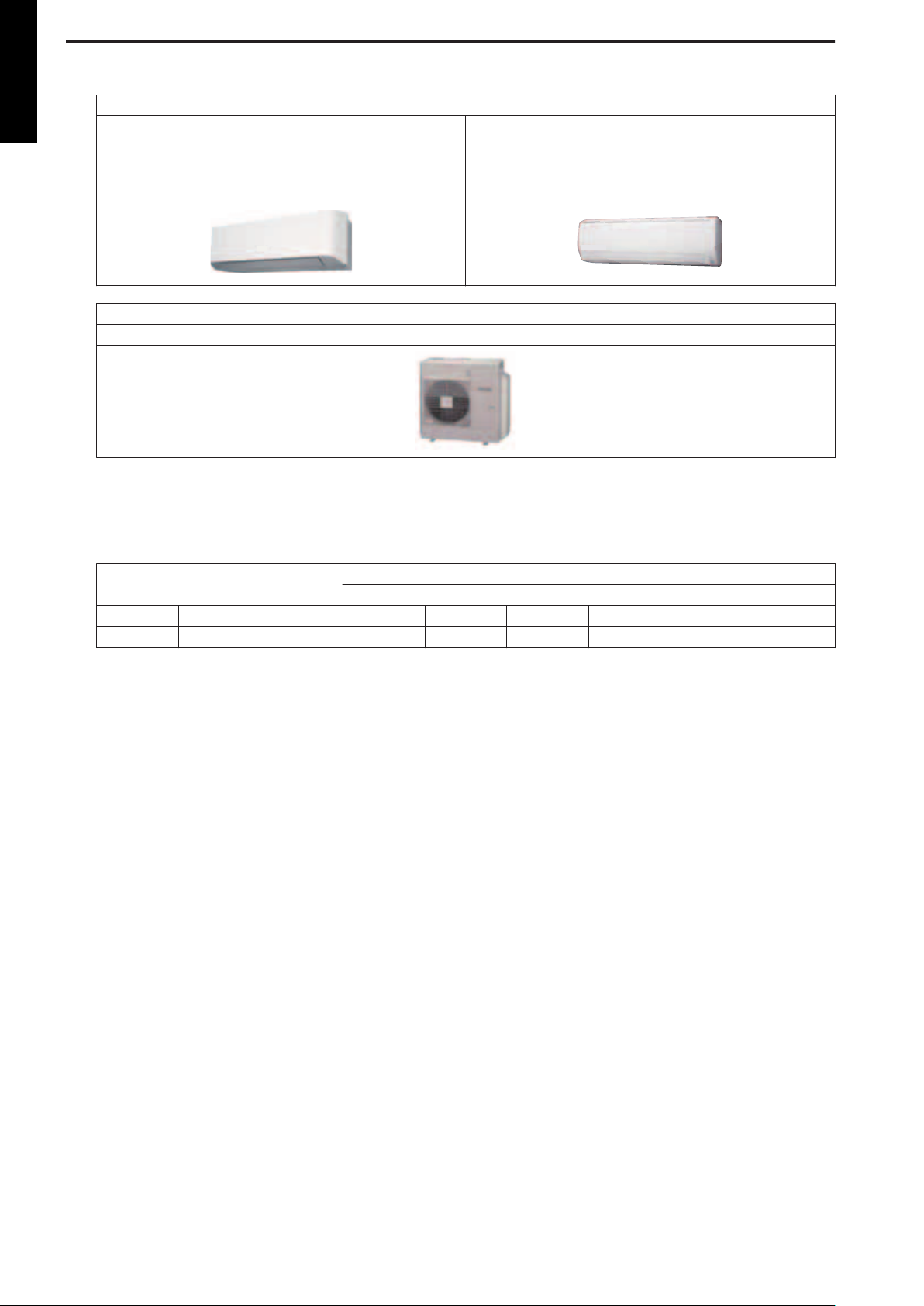
1. Model lineup
MULTI TYPE
5 rooms type
Indoor unit
RIWH07AVFJ
RIWH09AVFJ
RIWH12AVFJ
RIWH15AVFJ
Outdoor unit
ROMH45AFXZJ
RIWH18AVFJ
RIWH24AVFJ
Indoor units that can be connected to each outdoor unit
●: Connectable / -: Not connectable
Outdoor unit
kBtu Class 07 09 12 15 18 24
5 Rooms ROMH45AFXZJ ● ● ● ● ● ●
Wall mounted
RIWH07—24AVFJ
- 2 -
Page 9

1-1. Indoor unit connection patterns
5 rooms
ROMH45AFXZJ
No. room 1 room 2 room 3 room 4 room 5 total
1 18 18 — — — 36
2 12 24 — — — 36
3 15 24 — — — 39
4 18 24 — — — 42
5 24 24 — — — 48
6 7 7 24 — — 38
7 7 9 18 — — 34
8 7 9 24 — — 40
9 7 12 18 — — 37
10 7 12 24 — — 43
11 7 15 15 — — 37
12 7 15 18 — — 40
13 7 15 24 — — 46
14 7 18 18 — — 43
15 7 18 24 — — 49
16 9 9 18 — — 36
17 9 9 24 — — 42
18 9 12 15 — — 36
19 9 12 18 — — 39
20 9 12 24 — — 45
21 9 15 15 — — 39
22 9 15 18 — — 42
23 9 15 24 — — 48
24 9 18 18 — — 45
25 9 18 24 — — 51
26 12 12 12 — — 36
27 12 12 15 — — 39
28 12 12 18 — — 42
29 12 12 24 — — 48
30 12 15 15 — — 42
31 12 15 18 — — 45
32 12 15 24 — — 51
33 12 18 18 — — 48
34 12 18 24 — — 54
35 15 15 15 — — 45
36 15 15 18 — — 48
37 15 15 24 — — 54
38 15 18 18 — — 51
39 18 18 18 — — 54
40 7 7 7 15 — 36
41 7 7 7 18 — 39
42 7 7 7 24 — 45
43 7 7 9 12 — 35
44 7 7 9 15 — 38
45 7 7 9 18 — 41
46 7 7 9 24 — 47
47 7 7 12 12 — 38
48 7 7 12 15 — 41
49 7 7 12 18 — 44
50 7 7 12 24 — 50
MULTI TYPE
5 rooms type
- 3 -
Page 10

MULTI TYPE
5 rooms type
ROMH45AFXZJ
51 7 7 15 15 — 44
52 7 7 15 18 — 47
53 7 7 15 24 — 53
54 7 7 18 18 — 50
55 7 9 9 9 — 34
56 7 9 9 12 — 37
57 7 9 9 15 — 40
58 7 9 9 18 — 43
59 7 9 9 24 — 49
60 7 9 12 12 — 40
61 7 9 12 15 — 43
62 7 9 12 18 — 46
63 7 9 12 24 — 52
64 7 9 15 15 — 46
65 7 9 15 18 — 49
66 7 9 18 18 — 52
67 7 12 12 12 — 43
68 7 12 12 15 — 46
69 7 12 12 18 — 49
70 7 12 15 15 — 49
71 7 12 15 18 — 52
72 7 15 15 15 — 52
73 9 9 9 9 — 36
74 9 9 9 12 — 39
75 9 9 9 15 — 42
76 9 9 9 18 — 45
77 9 9 9 24 — 51
78 9 9 12 12 — 42
79 9 9 12 15 — 45
80 9 9 12 18 — 48
81 9 9 12 24 — 54
82 9 9 15 15 — 48
83 9 9 15 18 — 51
84 9 9 18 18 — 54
85 9 12 12 12 — 45
86 9 12 12 15 — 48
87 9 12 12 18 — 51
88 9 12 15 15 — 51
89 9 12 15 18 — 54
90 12 12 12 12 — 48
91 12 12 12 15 — 51
92 12 12 12 18 — 54
93 12 12 12 18 — 54
94 12 12 15 15 — 54
95 7 7 7 7 7 35
96 7 7 7 7 9 37
97 7 7 7 7 12 40
98 7 7 7 7 15 43
99 7 7 7 7 18 46
100 7 7 7 7 24 52
101 7 7 7 9 9 39
102 7 7 7 9 12 42
103 7 7 7 9 15 45
104 7 7 7 9 18 48
105 7 7 7 9 24 54
106 7 7 7 12 12 45
- 4 -
Page 11

ROMH45AFXZJ
107 7 7 7 12 15 48
108 7 7 7 12 18 51
109 7 7 7 15 15 51
110 7 7 7 15 18 54
111 7 7 9 9 9 41
112 7 7 9 9 12 44
113 7 7 9 9 15 47
114 7 7 9 9 18 50
115 7 7 9 12 12 47
116 7 7 9 12 15 50
117 7 7 9 12 18 53
118 7 7 9 15 15 53
119 7 7 12 12 12 50
120 7 7 12 12 15 53
121 7 9 9 9 9 43
122 7 9 9 9 12 46
123 7 9 9 9 15 49
124 7 9 9 9 18 52
125 7 9 9 12 12 49
126 7 9 9 12 15 52
127 7 9 12 12 12 52
128 9 9 9 9 9 45
129 9 9 9 9 12 48
130 9 9 9 9 15 51
131 9 9 9 9 18 54
132 9 9 9 12 12 51
133 9 9 9 12 15 54
134 9 9 12 12 12 54
MULTI TYPE
5 rooms type
7: 7,000Btu/h, 9: 9,000Btu/h, 12: 12,000Btu/h, 15: 14,000Btu/h, 18: 18,000Btu/h,
24: 24,000Btu/h
- 5 -
Page 12
2. Specifications
MULTI TYPE
2-1. Wall mounted type
5 rooms type
Model name RIWH07AVFJ RIWH09AVFJ RIWH12AVFJ RIWH15AVFJ
Power supply 208/230 V ~ 60 Hz
Available voltage range 187—264 V
Capacity Btu/h class 7,000 9,000 12,000 14,000
Input power W 15 17 22 28
Running current A 0.13 0.15 0.19 0.25
Fan
Sound pressure level *
Heat exchanger type
Enclosure
Dimensions
(H × W × D)
Weight
Connection
pipe
Drain hose
Operation range
Remote controller type Wireless (Wired [option])
NOTES:
HIGH
Cooling
Airflow rate
Heating
Type × Q'ty Cross flow fan × 1
Motor output W 30
Cooling
Heating
Dimensions (H × W × D) in (mm)
Fin pitch FPI Main: 23, Sub: 18
Rows × Stages Main: 2 × 20, Sub: 1 × 4
Pipe type Copper tube
Material Polystyrene
Color
Net
Gross 10-5/8 × 36-7/16 × 13-1/4 (270 × 925 × 336)
Net
Gross 24 (11)
Size
Method Flare
Material PP + LLDPE
Size in (mm) Ø 9/16(I.D.), Ø 5/8 to Ø 11/16(O.D.) [Ø 13.8(I.D.), Ø 15.8 to Ø 16.7(O.D.)]
• The protective function might work when using it outside the operation range.
• *Sound pressure level:
– Measured values in manufacturer’s anechoic chamber.
– Because of the surrounding sound environment, the sound levels measured in actual installation conditions might be higher than the specified values here.
Fin type Aluminum
Liquid
Gas Ø3/8 (Ø9.52) Ø1/2 (Ø12.70)
Cooling
Heating °F (°C) 60 to 88 (16 to 30)
MED 294 (500) 306 (520) 330 (560) 353 (600)
LOW 253 (430) 253 (430) 265 (450) 312 (530)
QUIET 182 (310) 182 (310) 182 (310) 212 (360)
HIGH 330 (560) 353 (600) 388 (660) 430 (730)
MED 294 (500) 306 (520) 330 (560) 362 (615)
LOW 253 (430) 253 (430) 277 (470) 330 (560)
QUIET 194 (330) 194 (330) 194 (330) 221 (375)
HIGH
MED 32 33 36 38
LOW 29 29 30 33
QUIET 21 21 21 25
HIGH 36 37 40 42
MED 32 33 36 38
LOW 29 29 31 35
QUIET 22 22 22 27
CFM (m3/h)
dB (A)
in (mm)
lb (kg)
in (mm)
°F (°C) 64 to 90 (18 to 32)
%RH 80 or less
330 (560) 353 (600) 388 (660) 430 (730)
36 37 40 42
Main: 12-5/8 × 24-13/16 × 13/16 (320 × 630 × 20)
Sub: 3-5/16 × 24-13/16 × 1/2 (84 × 630 × 13.3)
(Approximate color of MUNSELL N9.25 /)
10-5/8 × 34-1/4 × 8-1/16 (270 × 870 × 204)
White
19 (8.5)
Ø1/4 (Ø6.35)
- 6 -
Page 13
Model name RIWH18AVFJ RIWH24AVFJ
Power supply 208/230 V ~ 60 Hz
Available voltage range 187—264 V
Capacity Btu/h class 18,000 24,000
Input power W 41 69
Running current A 0.32 0.53
Cooling
Fan
Sound pressure level *
Heat exchanger type
Enclosure
Dimensions
(H × W × D)
Weight
Connection pipe
Drain hose
Operation range
Remote controller type Wireless (Wired [option])
NOTES:
• The protective function might work when using it outside the operation range.
• *Sound pressure level:
– Measured values in manufacturer’s anechoic chamber.
– Because of the surrounding sound environment, the sound levels measured in actual installation conditions might be higher than the specified values here.
Airflow rate
Heating
Type × Q'ty Cross flow fan ×1
Motor output W 42
Cooling
Heating
Dimensions (H × W × D) in (mm)
Fin pitch FPI Main: 21, Sub: 18
Rows × Stages Main: 2 × 18, Sub: 1 × 4
Pipe type Copper tube
Material Polystyrene
Color
Net
Gross 12-15/16 × 42-15/16 × 16-9/16 (329 × 1,090 × 420)
Net
Gross 40 (18)
Size
Method Flare
Material PVC
Size in (mm) Ø 1/2(I.D.), Ø 5/8(O.D.) [Ø 12(I.D.), Ø 16(O.D.)]
Fin type Aluminum
Liquid
Gas Ø1/2 (Ø12.70) Ø5/8 (Ø15.88)
Cooling
Heating °F (°C) 60 to 88 (16 to 30)
HIGH
MED 436 (740) 530 (900)
LOW 365 (620) 436 (740)
QUIET 324 (550) 365 (620)
HIGH 542 (920) 647 (1,100)
MED 436 (740) 530 (900)
LOW 365 (620) 436 (740)
QUIET 324 (550) 365 (620)
HIGH
MED 37 42
LOW 33 37
QUIET 31 33
HIGH 44 48
MED 37 42
LOW 33 37
QUIET 31 33
CFM (m3/h)
dB (A)
in (mm)
lb (kg)
mm (in)
°F (°C) 64 to 90 (18 to 32)
%RH 80 or less
542 (920) 659 (1,120)
43 49
Main: 15-7/8 × 33-3/4 × 1-1/16 (378 × 832 × 26.6)
Sub: 3-5/16 × 33-3/4 × 1/2 (84 × 832 × 13.3)
(Approximate color of MUNSELL N9.25 /)
12-5/8 × 39-5/16 × 9-3/8 (320 × 998 × 238)
White
31 (14)
Ø1/4 (Ø6.35)
MULTI TYPE
5 rooms type
- 7 -
Page 14
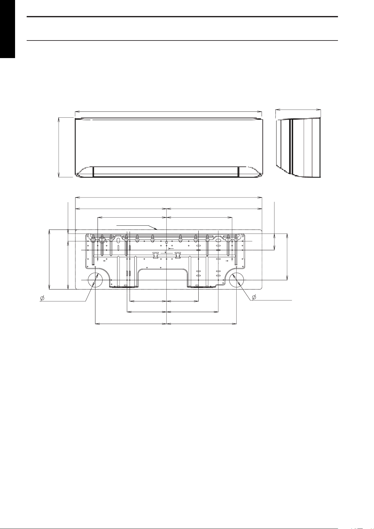
3. Dimensions
10-5/8 (270)
34-1/4 (870)
8-1/16 (204)
Outline of unit
Unit: in (mm)
[10-5/8 (270)]
1-5/16 (34)
8-9/16 (217)
8-1/4 (209)
2-15/16(74)
[34-1/4 (870)]
16-3/4 (426)
12-3/16 (310)
17-1/2 (444)
6-1/2 (165) 5-11/16 (144)
7 (178) 9-3/16 (233)
12-5/8 (321) 12-3/8 (315)
11-5/8 (295)
2-9/16 (65)
for pipe inlet
2-9/16 (65)
for pipe inlet
MULTI TYPE
3-1. Wall mounted type
5 rooms type
¢ Models: RIWH07AVFJ, RIWH09AVFJ, RIWH12AVFJ, and RI-
WH15AVFJ
- 8 -
Page 15
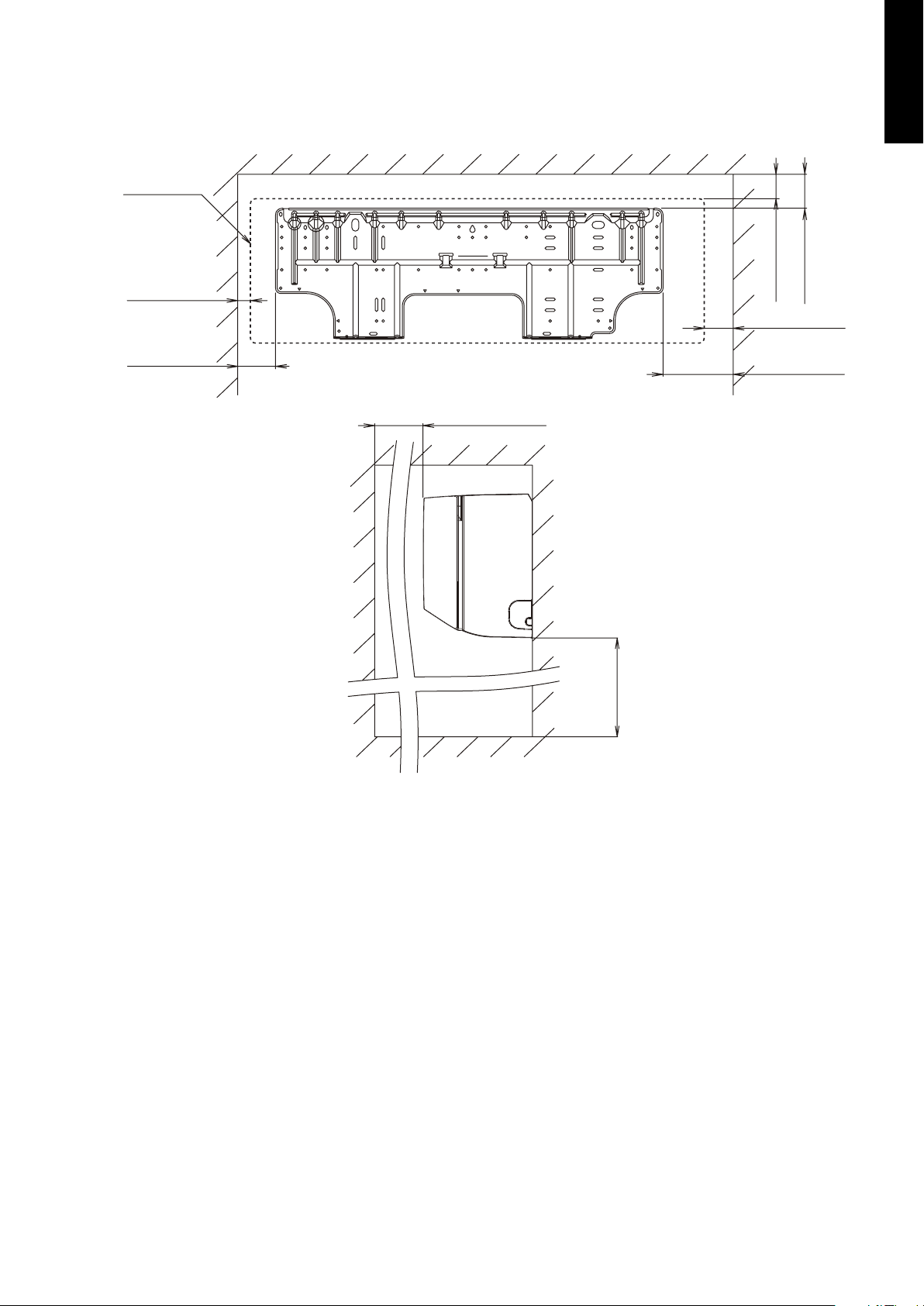
Installation space requirement
Unit: in (mm
)
2 (45) or more
71 (1,800)
or more
3 (63) or more
Outline of unit
1 (25) or more
3 (52) or more
6 (144) or more
60 (1,500) or more
4 (86) or more
Provide sufficient installation space for product safety.
MULTI TYPE
5 rooms type
- 9 -
Page 16
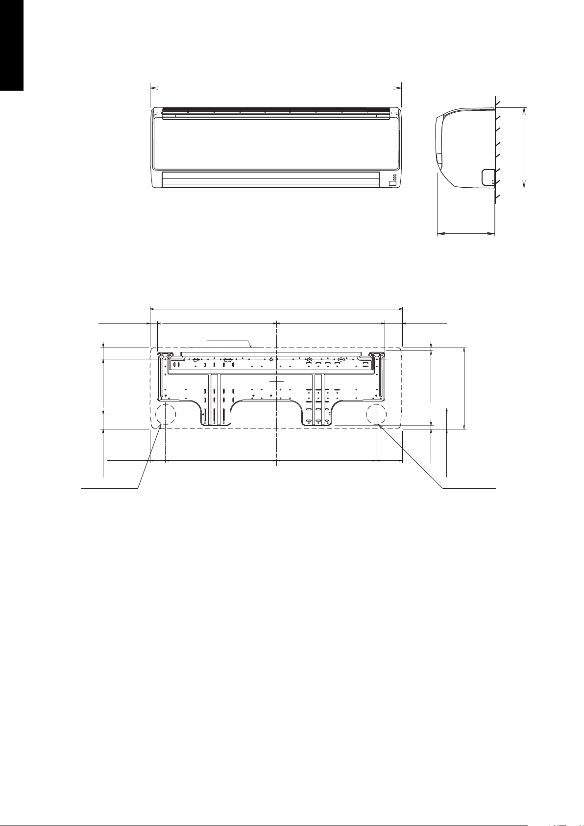
39-5/16 (998)
9 (238)
12-5/8 (320)
39-5/16 (998)
Outline of unit
18-9/16 (471)
2-5/8 (67)
1-1/8 (28)
1-13/16 (46)
17-1/4 (438)2-3/8 (61) 4 (102)15-5/8 (397)
17 (432)
2-3/16 (56)
2-3/16 (56)
3/8 (10)
12-5/8 (320)
11/16 (17)
Ø 3-1/8 (80) hole
Piping inlet
Ø 3-1/8 (80) hole
Piping inlet
Unit: in (mm)
MULTI TYPE
5 rooms type
Models: RIWH18AVFJ and RIWH24AVFJ
¢
- 10 -
Page 17
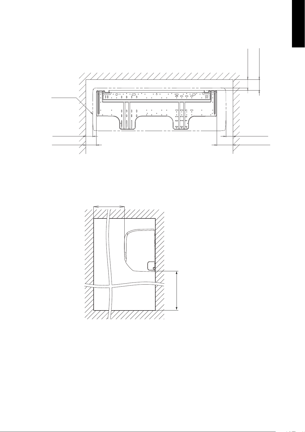
Installation space requirement
Unit: in (mm)
3 (63) or more
4 (80) or more
3 (52) or more 3 (53) or more
4 (80) or more
Outline of unit
5 (120) or more
60 (1,500) or more
71 (1,800) or more
Provide sufficient installation space for product safety.
MULTI TYPE
5 rooms type
- 11 -
Page 18
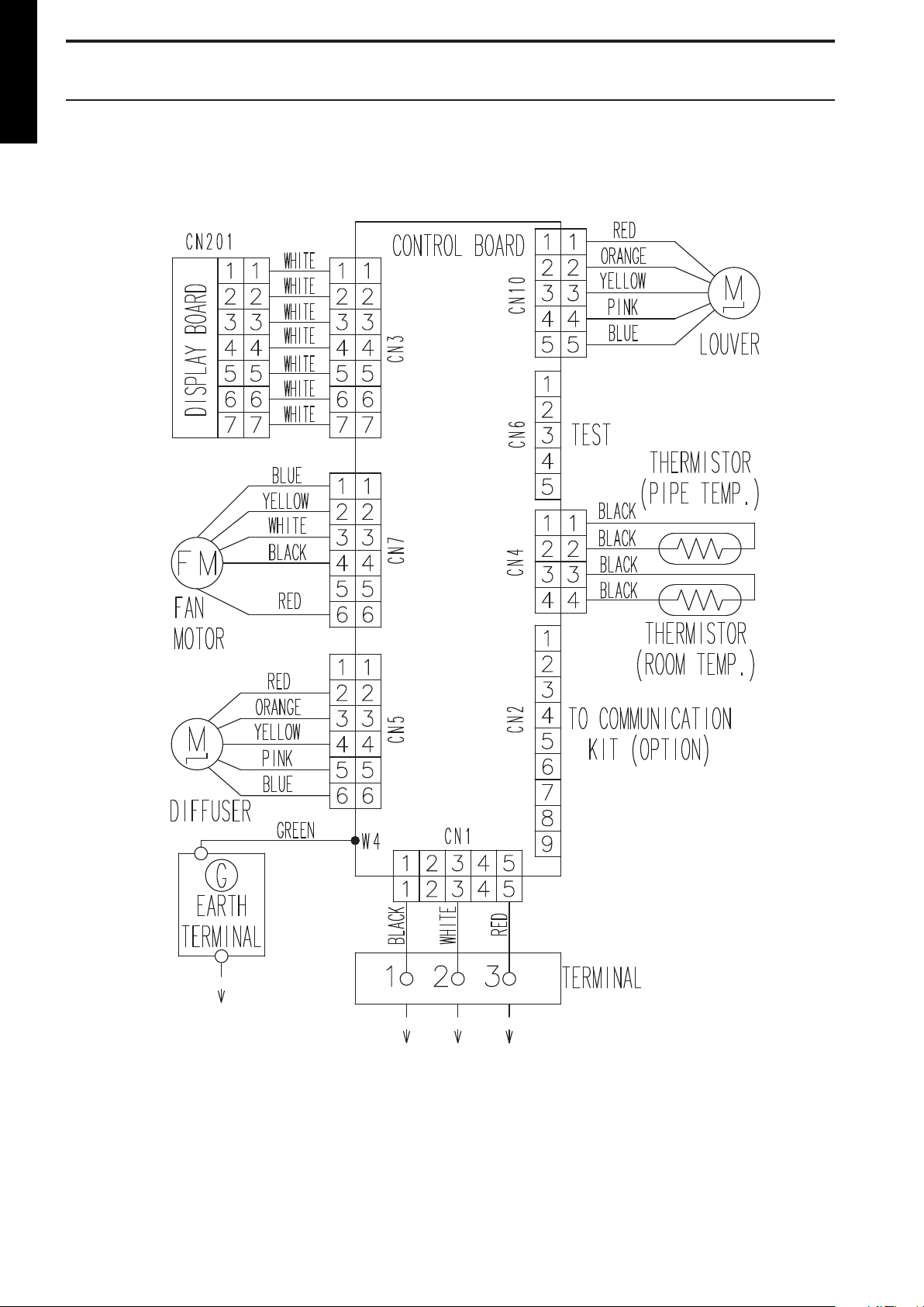
4. Wiring diagrams
MULTI TYPE
4-1. Wall mounted type
5 rooms type
¢ Models: RIWH07AVFJ, RIWH09AVFJ, RIWH12AVFJ, and RI-
WH15AVFJ
- 12 -
Page 19
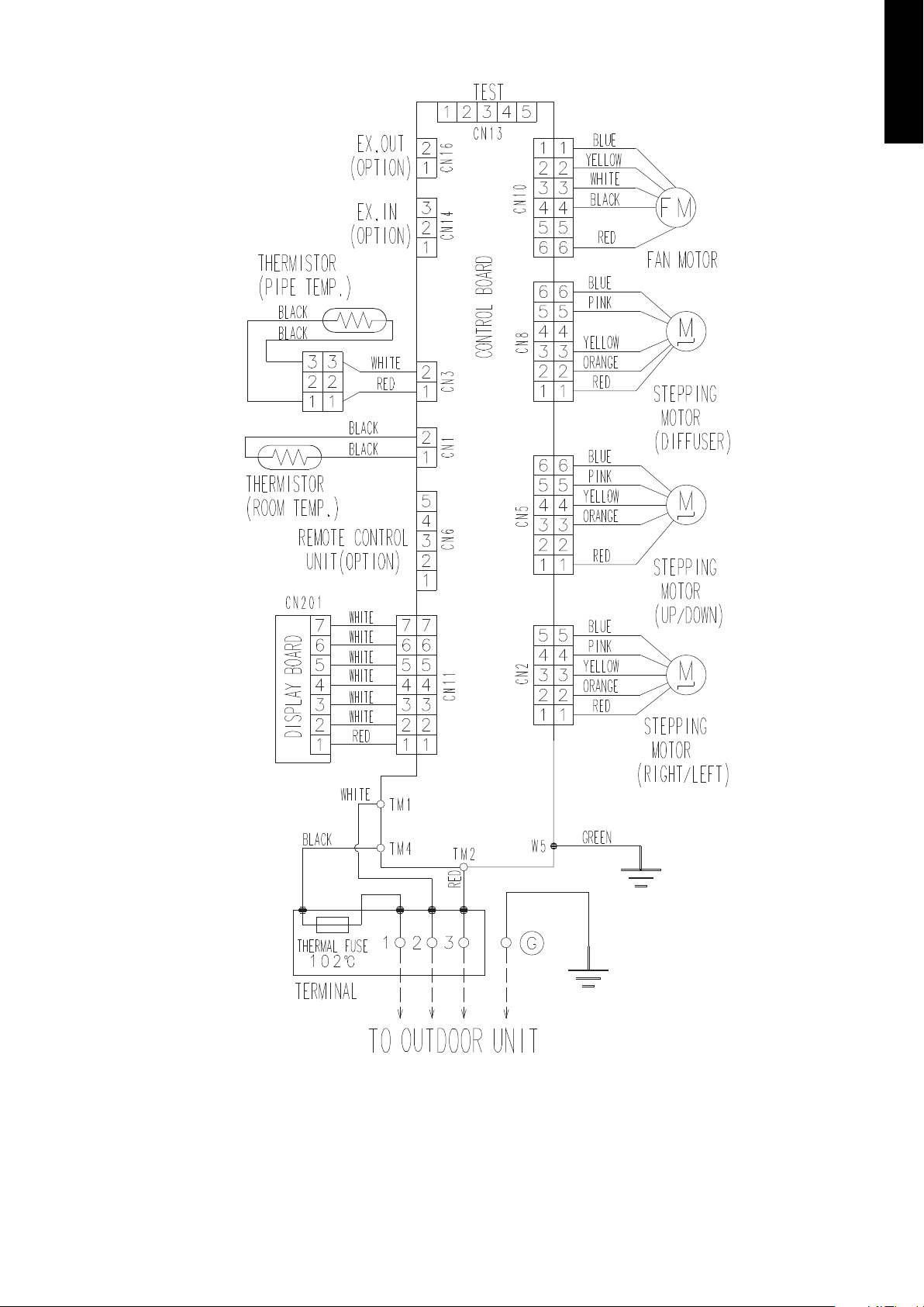
Models: RIWH18AVFJ and RIWH24AVFJ
¢
MULTI TYPE
5 rooms type
- 13 -
Page 20
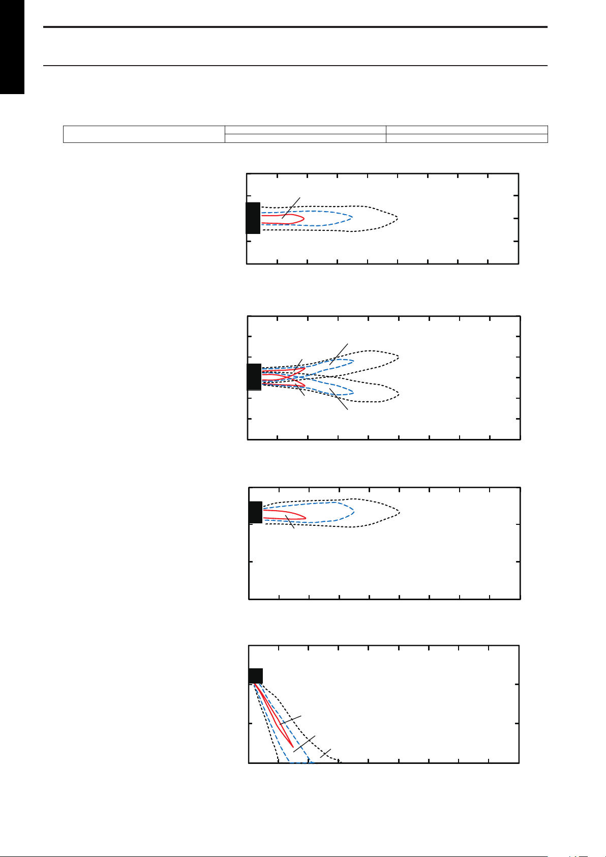
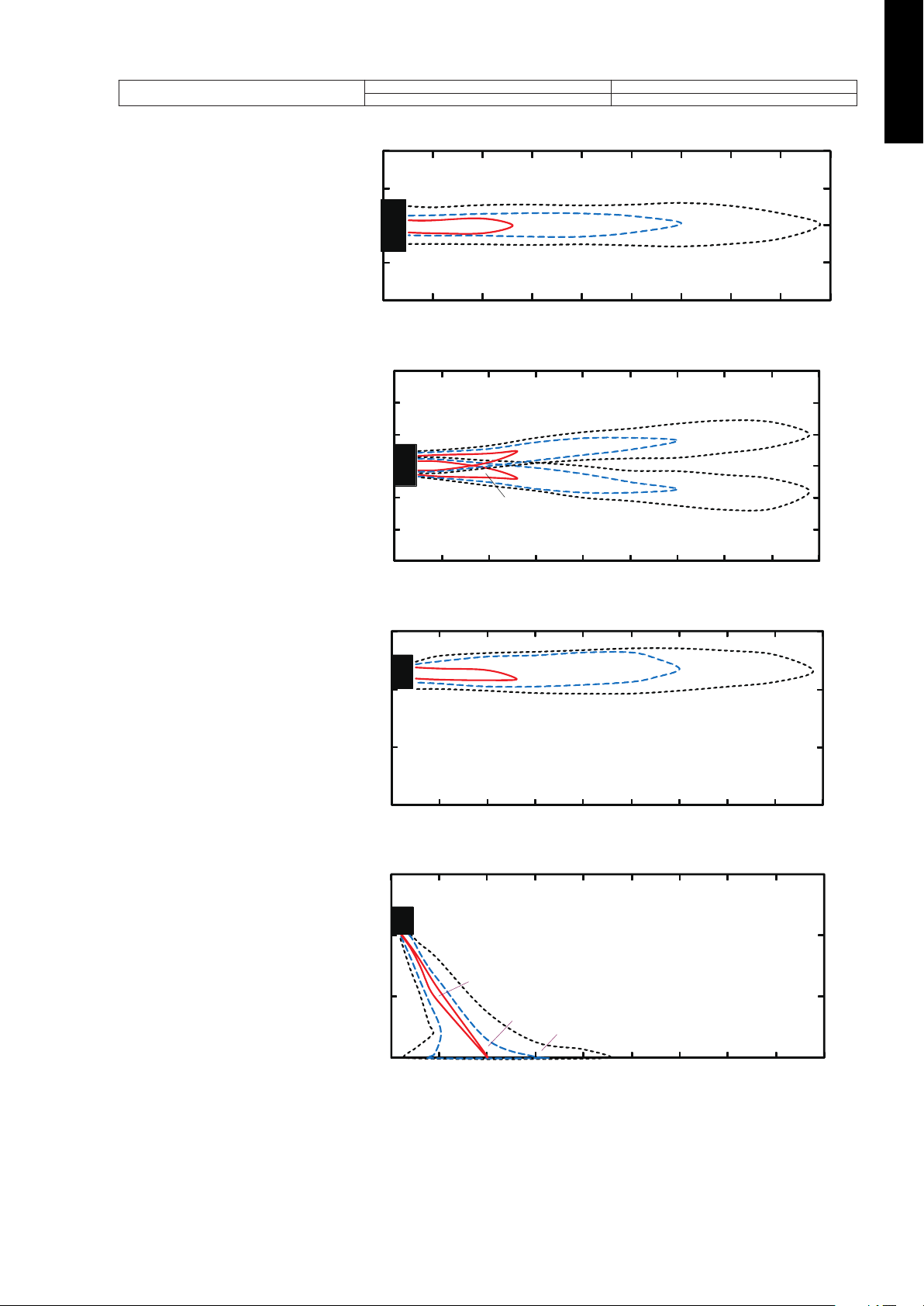
5. Air velocity and temperature distributions
7 (2.0)
3 (1.0) 2 (0.5)
2
1
0
1
2
Unit: ft/s (m/s)
(m)
(m)
01234567
8
7
3
0
3
7
(ft)
(ft)
0 3 7 10 13 16 20 23
26
9
29
7 (2.0)
7 (2.0)
2 (0.5)
2 (0.5)
3 (1.0)
3 (1.0)
10
7
3
0
3
7
10
(ft)
(ft)
0 3 7 10 13 16 20 23
26
3
2
1
0
1
2
3
Unit: ft/s (m/s)
(m)
(m)
01234567
8
9
29
7 (2.0)
2 (0.5)
3 (1.0)
3
2
1
0
Unit: ft/s (m/s)
(m)
(m)
012345678
10
7
3
0
(ft)
(ft)
0 3 7 10 13 16 20 23 26
9
29
2 (0.5)
7 (2.0)
3 (1.0)
3
2
1
0
Unit: ft/s (m/s)
(m)
(m)
012345678
10
7
3
0
(ft)
(ft)
0 3 7 10 13 16 20 23 26
9
29
MULTI TYPE
5-1. Wall mounted type
5 rooms type
Model: RIWH07AVFJ
¢
Measuring conditions
Top view
Vertical airflow direction louver: Up
Horizontal airflow direction louver: Center
Top view
Vertical airflow direction louver: Up
Horizontal airflow direction louver: Left & Right
Fan speed Operation mode
HIGH FAN
Side view
Vertical airflow direction louver: Up
Horizontal airflow direction louver: Center
Side view
Vertical airflow direction louver: Down
Horizontal airflow direction louver: Center
- 14 -
Page 21

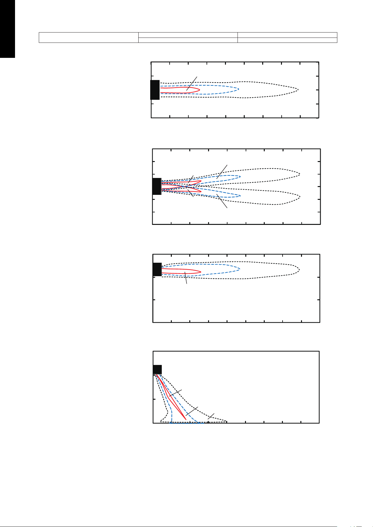
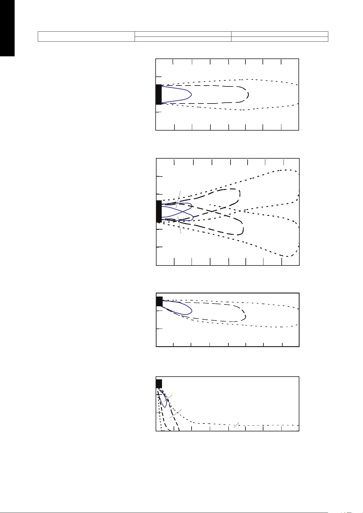
Model: RIWH09AVFJ
7 (2.0)
3 (1.0) 2 (0.5)
2
1
0
1
2
Unit: ft/s (m/s)
(m)
(m)
01234567
8
7
3
0
3
7
(ft)
(ft)
0 3 7 10 13 16 20 23
26
9
29
7 (2.0)
7 (2.0)
2 (0.5)
2 (0.5)
3 (1.0)
3 (1.0)
10
7
3
0
3
7
10
(ft)
(ft)
0 3 7 10 13 16 20 23
26
3
2
1
0
1
2
3
Unit: ft/s (m/s)
(m)
(m)
01234567
8
9
29
3 (1.0) 2 (0.5)
7 (2.0)
3
2
1
0
Unit: ft/s (m/s)
(m)
(m)
012345678
10
7
3
0
(ft)
(ft)
0 3 7 10 13 16 20 23 26
9
29
3 (1.0)
2 (0.5)
7 (2.0)
3
2
1
0
Unit: ft/s (m/s)
(m)
(m)
012345678
10
7
3
0
(ft)
(ft)
0 3 7 10 13 16 20 23 26
9
29
¢
Measuring conditions
Top view
Vertical airflow direction louver: Up
Horizontal airflow direction louver: Center
Top view
Vertical airflow direction louver: Up
Horizontal airflow direction louver: Left & Right
Fan speed Operation mode
HIGH FAN
MULTI TYPE
5 rooms type
Side view
Vertical airflow direction louver: Up
Horizontal airflow direction louver: Center
Side view
Vertical airflow direction louver: Down
Horizontal airflow direction louver: Center
- 15 -
Page 22
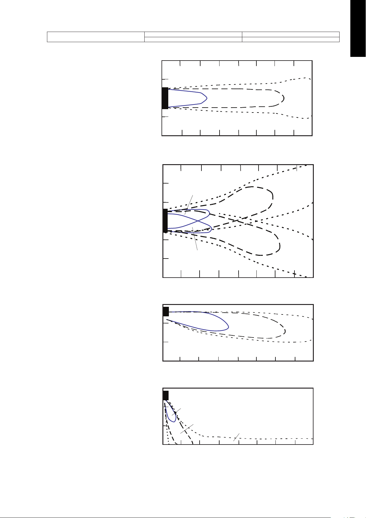
Model: RIWH12AVFJ
3 (1.0) 2 (0.5)
7 (2.0)
2
1
0
1
2
Unit: ft/s (m/s)
(m)
(m)
01234567
8
7
3
0
3
7
(ft)
(ft)
0 3 7 10 13 16 20 23
26
9
29
7 (2.0)
7 (2.0)
2 (0.5)
2 (0.5)
3 (1.0)
3 (1.0)
10
7
3
0
3
7
10
(ft)
(ft)
0 3 7 10 13 16 20 23
26
3
2
1
0
1
2
3
Unit: ft/s (m/s)
(m)
(m)
01234567
8
9
29
3 (1.0)
2 (0.5)
7 (2.0)
3
2
1
0
Unit: ft/s (m/s)
(m)
(m)
012345678
10
7
3
0
(ft)
(ft)
0 3 7 10 13 16 20 23 26
9
29
7 (2.0)
3 (1.0)
2 (0.5)
3
2
1
0
Unit: ft/s (m/s)
(m)
(m)
012345678
10
7
3
0
(ft)
(ft)
0 3 7 10 13 16 20 23 26
9
29
¢
MULTI TYPE
5 rooms type
Measuring conditions
Top view
Vertical airflow direction louver: Up
Horizontal airflow direction louver: Center
Top view
Vertical airflow direction louver: Up
Horizontal airflow direction louver: Left & Right
Fan speed Operation mode
HIGH FAN
Side view
Vertical airflow direction louver: Up
Horizontal airflow direction louver: Center
Side view
Vertical airflow direction louver: Down
Horizontal airflow direction louver: Center
- 16 -
Page 23
Model: RIWH15AVFJ
7 (2.0)
3 (1.0)
2 (0.5)
2
1
0
1
2
Unit: ft/s (m/s)
(m)
(m)
0123456
78
7
3
0
3
7
(ft)
(ft)
03710131620
23
26
9
29
3 (1.0)
3 (1.0)
2 (0.5)
2 (0.5)
7 (2.0)
7 (2.0)
10
7
3
0
3
7
10
(ft)
(ft)
03
710 13162023
26
3
2
1
0
1
2
3
Unit: ft/s (m/s)(m)
(m)
01
23 4567
8
9
29
7 (2.0)
3 (1.0)
2 (0.5)
3
2
1
0
Unit: ft/s (m/s)
(m)
(m)
012345678
10
7
3
0
(ft)
(ft)
037101316202326
9
29
7 (2.0)
3 (1.0)
2 (0.5)
3
2
1
0
Unit: ft/s (m/s)
(m)
(m)
012 34 5 67 8
10
7
3
0
(ft)
(ft)
0 3 7 10 13 16 20 23 26
9
29
¢
Measuring conditions
Top view
Vertical airflow direction louver: Up
Horizontal airflow direction louver: Center
Top view
Vertical airflow direction louver: Up
Horizontal airflow direction louver: Left & Right
Fan speed Operation mode
HIGH FAN
MULTI TYPE
5 rooms type
Side view
Vertical airflow direction louver: Up
Horizontal airflow direction louver: Center
Side view
Vertical airflow direction louver: Down
Horizontal airflow direction louver: Center
- 17 -
Page 24
Model: RIWH18AVFJ
Unit: ft/s (m/s)
(m)(ft)
0
0
3
3
7
7
1
1
2
2
(m)
(ft)
0
0
1
3 7 10 13 16 20 23 26
2345678
7 (2.0)
3 (1.0)
2 (0.5)
7 (2.0)
7 (2.0)
3 (1.0)
3 (1.0)
2 (0.5)
2 (0.5)
Unit: ft/s (m/s)
(m)
(ft)
0
0
1
3 7 10 13 16 20 23 26
2345678
(m)(ft)
00
3
3
7
7
1
1
2
2
3310
10
3
2
1
0
Unit: ft/s (m/s)
(m)
(m)
012345678
10
7
3
0
(ft)
(ft)
0 3 7 101316202326
7 (2.0)
3 (1.0)
2 (0.5)
7 (2.0)
3 (1.0)
2 (0.5)
3
2
1
0
Unit: ft/s (m/s)
(m)
(m)
012345678
10
7
3
0
(ft)
(ft)
0 3 7 101316202326
¢
MULTI TYPE
5 rooms type
Measuring conditions
Top view
Vertical airflow direction louver: Up
Horizontal airflow direction louver: Center
Top view
Vertical airflow direction louver: Up
Horizontal airflow direction louver: Left & Right
Fan speed Operation mode
HIGH FAN
Side view
Vertical airflow direction louver: Up
Horizontal airflow direction louver: Center
Side view
Vertical airflow direction louver: Down
Horizontal airflow direction louver: Center
- 18 -
Page 25
Model: RIWH24AVFJ
7 (2.0)
3 (1.0)
2 (0.5)
(m)(ft)
0
0
3
3
7
7
1
1
2
2
(m)
(ft)
0
0
1
3 7 10 13 16 20 23 26
2345678
Unit: ft/s (m/s)
7 (2.0)
7 (2.0)
3 (1.0)
3 (1.0)
2 (0.5)
2 (0.5)
Unit: ft/s (m/s)
(m)
(ft)
0
0
1
3 7 10 13 16 20 23 26
2345678
(m)(ft)
00
3
3
7
7
1
1
2
2
3310
10
7 (2.0)
3 (1.0)
2 (0.5)
Unit: ft/s (m/s)
(m)
(ft)
0
0
1
3 7 10 13 16 20 23 26
2345678
(m)(ft)
0
0
3
7
10
1
2
3
7 (2.0)
3 (1.0)
2 (0.5)
Unit: ft/s (m/s)
(m)
(ft)
0
0
1
3 7 10 13 16 20 23 26
2345678
(m)(ft)
0
0
3
7
10
1
2
3
¢
Measuring conditions
Top view
Vertical airflow direction louver: Up
Horizontal airflow direction louver: Center
Fan speed Operation mode
HIGH FAN
MULTI TYPE
5 rooms type
Top view
Vertical airflow direction louver: Up
Horizontal airflow direction louver: Left & Right
Side view
Vertical airflow direction louver: Up
Horizontal airflow direction louver: Center
Side view
Vertical airflow direction louver: Down
Horizontal airflow direction louver: Center
- 19 -
Page 26
6. Airflow
MULTI TYPE
5 rooms type
6-1. Wall mounted type
Conversion factor:
• 1 m3/h = 0.2778 l/s = 0.5886 CFM
• 3.6 m3/h = 1 l/s
• 1.699 m3/h = 1 CFM
Model
RIWH07AVFJ
RIWH09AVFJ
RIWH12AVFJ
RIWH15AVFJ
RIWH18AVFJ
Operation
mode
Cooling
Heating
Cooling
Heating
Cooling
Heating
Cooling
Heating
Cooling
Heating
Airflow
Fan speed
m3/h
High 560 156 330
Med 500 139 294
Low 430 119 253
Quiet 310 86 182
High 560 156 330
Med 500 139 294
Low 430 119 253
Quiet 330 92 194
High 600 167 353
Med 520 144 306
Low 430 119 253
Quiet 310 86 182
High 600 167 353
Med 520 144 306
Low 430 119 253
Quiet 330 92 194
High 660 183 388
Med 560 156 330
Low 450 125 265
Quiet 310 86 182
High 660 183 388
Med 560 156 330
Low 470 131 277
Quiet 330 92 194
High 730 203 430
Med 600 167 353
Low 530 147 312
Quiet 360 100 212
High 730 203 430
Med 615 171 362
Low 560 156 330
Quiet 375 104 221
High 920 256 542
Med 740 206 436
Low 620 172 365
Quiet 550 153 324
High 920 256 542
Med 740 206 436
Low 620 172 365
Quiet 550 153 324
l/s CFM
- 20 -
Page 27

Model
RIWH24AVFJ
Operation
mode
Cooling
Heating
Airflow
Fan speed
m3/h
l/s CFM
High 1,120 311 659
Med 900 250 530
Low 740 206 436
Quiet 620 172 365
High 1,100 306 647
Med 900 250 530
Low 740 206 436
Quiet 620 172 365
MULTI TYPE
5 rooms type
- 21 -
Page 28
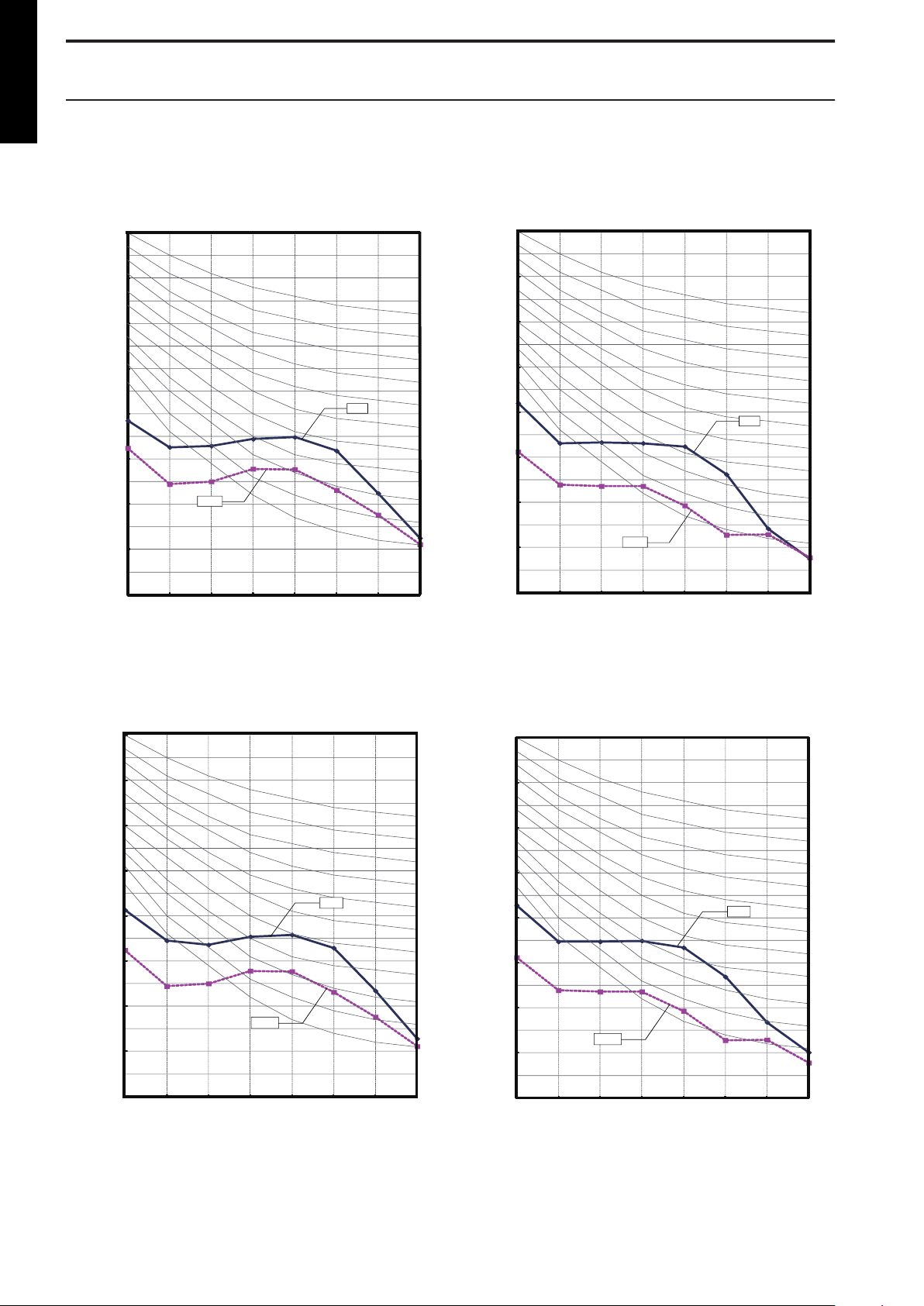
7. Noise level curve
0
10
20
30
40
50
60
70
80
63 125 250 500 1,000 2,000 4,000 8,000
Octave band sound pressure level, dB: (0 dB=0.00020 μbar)
Octave band center frequency, Hz
NC-65
NC-60
NC-55
NC-50
NC-45
NC-40
NC-35
NC-30
NC-25
NC-20
NC-15
High
Quiet
0
10
20
30
40
50
60
70
80
63 125 250 500 1,000 2,000 4,000 8,000
Octave band sound pressure level, dB: (0 dB=0.00020 μbar)
Octave band center frequency, Hz
NC-65
NC-60
NC-55
NC-50
NC-45
NC-40
NC-35
NC-30
NC-25
NC-20
NC-15
High
Quiet
0
10
20
30
40
50
60
70
80
63 125 250 500 1,000 2,000 4,000 8,000
Octave band sound pressure level, dB: (0 dB=0.00020 μbar)
Octave band center frequency, Hz
NC-65
NC-60
NC-55
NC-50
NC-45
NC-40
NC-35
NC-30
NC-25
NC-20
NC-15
High
Quiet
0
10
20
30
40
50
60
70
80
63 125 250 500 1,000 2,000 4,000 8,000
Octave band sound pressure level, dB: (0 dB=0.00020 μbar)
Octave band center frequency, Hz
NC-65
NC-60
NC-55
NC-50
NC-45
NC-40
NC-35
NC-30
NC-25
NC-20
NC-15
-
High
Quiet
MULTI TYPE
7-1. Wall mounted type
5 rooms type
Model: RIWH07AVFJ
¢
Cooling
Heating
Model: RIWH09AVFJ
¢
Cooling
Heating
- 22 -
Page 29
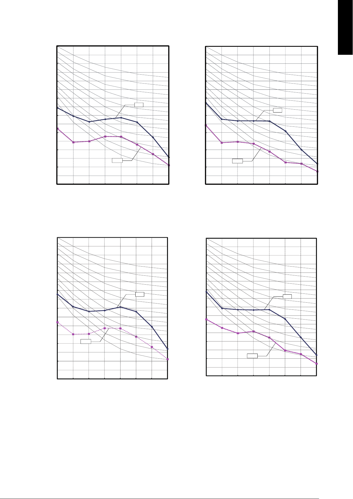
Model: RIWH12AVFJ
0
10
20
30
40
50
60
70
80
63 125 250 500 1,000 2,000 4,000 8,000
Octave band sound pressure level, dB: (0 dB=0.00020 μbar)
Octave band center frequency, Hz
NC-65
NC-60
NC-55
NC-50
NC-45
NC-40
NC-35
NC-30
NC-25
NC-20
NC-15
High
Quiet
0
10
20
30
40
50
60
70
80
63 125 250 500 1,000 2,000 4,000 8,000
Octave band sound pressure level, dB: (0 dB=0.00020 μbar)
Octave band center frequency, Hz
NC-65
NC-60
NC-55
NC-50
NC-45
NC-40
NC-35
NC-30
NC-25
NC-20
NC-15
High
Quiet
HIGH
㻽㼁㻵㻱㼀
0
10
20
30
40
50
60
70
80
63 125 250 500 1,000 2,000 4,000 8,000
Octave band sound pressure level, dB: (0 dB=0.00020 μbar)
Octave band center frequency, Hz
NC-65
NC-60
NC-55
NC-50
NC-45
NC-40
NC-35
NC-30
NC-25
NC-20
NC-15
HIGH
㻽㼁㻵㻱㼀
0
10
20
30
40
50
60
70
80
63 125 250 500 1,000 2,000 4,000 8,000
Octave band sound pressure level, dB: (0 dB=0.00020 μbar)
Octave band center frequency, Hz
NC-65
NC-60
NC-55
NC-50
NC-45
NC-40
NC-35
NC-30
NC-25
NC-20
NC-15
¢
Cooling
Heating
MULTI TYPE
5 rooms type
Model: RIWH15AVFJ
¢
Cooling
Heating
- 23 -
Page 30
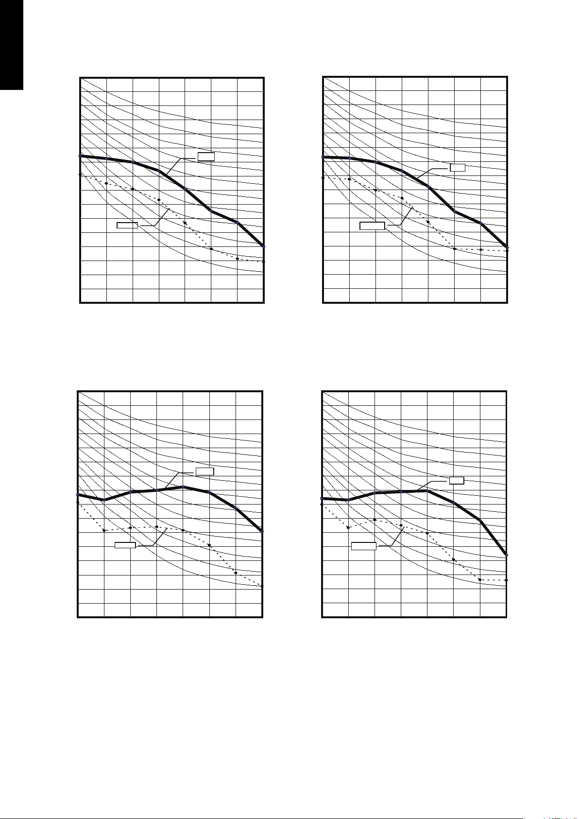
Model: RIWH18AVFJ
0
10
20
30
40
50
60
70
80
63 125 250 500 1,000 2,000 4,000 8,000
Octave band sound pressure level, dB: (0 dB=0.00020 μbar)
Octave band center frequency, Hz
NC-65
NC-60
NC-55
NC-50
NC-45
NC-40
NC-35
NC-30
NC-25
NC-20
NC-15
Quiet
H igh
0
10
20
30
40
50
60
70
80
63 125 250 500 1,000 2,000 4,000 8,000
Octave band sound pressure level, dB: (0 dB=0.00020 μbar)
Octave band center frequency, Hz
NC-65
NC-60
NC-55
NC-50
NC-45
NC-40
NC-35
NC-30
NC-25
NC-20
NC-15
H igh
Quiet
0
10
20
30
40
50
60
70
80
63 125 250 500 1,000 2,000 4,000 8,000
Octave band sound pressure level, dB: (0 dB=0.00020 μbar)
Octave band center frequency, Hz
NC-65
NC-60
NC-55
NC-50
NC-45
NC-40
NC-35
NC-30
NC-25
NC-20
NC-15
H igh
Quiet
0
10
20
30
40
50
60
70
80
63 125 250 500 1,000 2,000 4,000 8,000
Octave band sound pressure level, dB: (0 dB=0.00020 μbar)
Octave band center frequency, Hz
NC-65
NC-60
NC-55
NC-50
NC-45
NC-40
NC-35
NC-30
NC-25
NC-20
NC-15
H igh
Quiet
¢
MULTI TYPE
5 rooms type
Cooling
Heating
Model: RIWH24AVFJ
¢
Cooling
Heating
- 24 -
Page 31

7-2. Sound level check point
2 ft 7
-5/8
in (0.8 m)
3 ft 3
-3/8
in (1 m)
Microphone Microphone
Wall mounted type
¢
NOTE: Detailed shape of the actual indoor unit might be slightly different from the one illustrated
above.
MULTI TYPE
5 rooms type
- 25 -
Page 32

8. Electrical characteristics
MULTI TYPE
5 rooms type
Type Model name Hz
RIWH07AVFJ
RIWH09AVFJ 0.20 / 0.19 17 / 17 0.16 / 0.15
Wall mounted
RIWH12AVFJ 0.25 / 0.24 22 / 22 0.20 / 0.19
RIWH15AVFJ 0.34 / 0.31 28 / 28 0.27 / 0.25
RIWH18AVFJ 0.42 / 0.40 40 / 41 0.34 / 0.32
RIWH24AVFJ 0.71 / 0.66 68 / 69 0.57 / 0.53
Power supply Indoor rated
Voltage
(V)
60 208 / 230
MCA
(A)
0.18 / 0.16 15 / 15 0.14 / 0.13
Input power
(W)
FLA
(A)
Wiring spec.
(Indoor unit to outdoor unit)
Connection cable AWG 14
Limited wiring length ft (m) 85 (26)
MCA: Minimum Circuit Ampacity = Maximum operating current (Full load)
FLA: Full Load Amperes (Fan motor)
- 26 -
Page 33

9. Safety devices
Indoor unit
type
Wall mounted
Model name PCB* fuse
RIWH07AVFJ
RIWH09AVFJ
RIWH12AVFJ
RIWH15AVFJ
RIWH18AVFJ
RIWH24AVFJ
*: Printed Circuit Board
250 V, 3.15 A
Fan motor thermal
protector
Activate: 221 ±18 °F
(105 ±10 °C)
Fan motor stop
Reset: 194 ±18 °F
(90 ±10 °C)
Fan motor restart
Activate: 302 ±27 °F
(150 ±15 °C)
Fan motor stop
Reset: 248 ±27 °F
(120 ±15 °C)
Fan motor restart
Terminal thermal
fuse
― ―
Activate: 216 °F
(102 °C)
Float
switch
―
MULTI TYPE
5 rooms type
- 27 -
Page 34

10. External input and output
Indoor unit
control PCB*1
Example: Switch
Locally purchased
Connected unit
1
3
Signal
Connector
33 ft. (10 m)*2
MULTI TYPE
5 rooms type
10-1. External input
Indoor unit type
Wall mounted ● ●
External input External output
Control input Operation status output Error status output
●
(RIWH07/09/12/15AVFJ)
With using external input function, some functions on this product can be controlled from an external device.
• “Operation/Stop” mode or "Forced stop" mode can be selected with function setting of indoor
unit.
• A twisted pair cable (22AWG) should be used. Maximum length of cable is 492 ft (150 m).
• The wire connection should be separate from the power cable line.
Control input (Operation/Stop or Forced stop)
¢
Indoor unit type Connector
Wall mounted
RIWH07AVFJ, RIWH09AVFJ, RIWH12AVFJ,
RIWH15AVFJ
RIWH18AVFJ, RIWH24AVFJ CN14
CNA01
The air conditioner can be remotely operated by means of the following on-site work.
Operation is started at the following contents by adding the contact input of a commercial on/off
switch to a connector on the external control PCB and turning it on.
Unit operation Initial setting after power is on
Operation mode Auto changeover Mode at previous operation
Set temperature 76 °F (24 °C) Temperature at previous operation
Airflow mode AUTO Mode at previous operation
Air direction (swing) Standard air direction (swing: off) Air direction at previous operation
Starting mode other than initial
setting
Circuit diagram example
• Contact capacity: DC 24 V or more, 10 mA or more.
• *1: PCB of Communication kit is used for wall mounted (RIWH07AVFJ, RIWH09AVFJ, RIWH12AVFJ,
and RIWH15AVFJ) type.
• *2: Make the distance from the PCB to the connected unit within 33 ft (10 m).
• Use non-polar relays and switches.
Wall mounted
Indoor unit type
RIWH07AVFJ, RIWH09AVFJ, RIWH12AVFJ,
RIWH15AVFJ, RIWH18AVFJ, RIWH24AVFJ
- 28 -
1-pin 3-pin
(Polarity) (Polarity)
- +
Page 35

• When function setting is "Operation/Stop" mode
Operation
Stop
On
Off
Input signal
Indoor unit
Remote controller
On On On
Input signal
Indoor unit
Command
Remote control
operation invalidity
On
Off
Operation
Stop
Forced stop
Normal
• When function setting is "Forced stop" mode
MULTI TYPE
5 rooms type
Optional part
Indoor unit type Part name Model name
Wall mounted
Wall mounted
RIWH07AVFJ, RIWH09AVFJ, RIWH12AVFJ,
RIWH15AVFJ
RIWH18AVFJ, RIWH24AVFJ RXXWZX
Indoor unit type Part name Model name
RIWH07AVFJ, RIWH09AVFJ, RIWH12AVFJ,
RIWH15AVFJ
RIWH18AVFJ, RIWH24AVFJ — —
External connect
kit
Communication kit RXXCBXZ2
*For operating the external input function, the wall mounted (RIWH07AVFJ, RIWH09AVFJ,
RIWH12AVFJ, and RIWH15AVFJ) type requires optional communication kit (RXXCBXZ2) in
addition to the wire (RXXWZXZ5).
RXXWZXZ5
- 29 -
Page 36

10-2. External output
Locally purchased
Indoor unit
control PCB
*1
Connected unit
Example: Display
Example: Relay unit
Relay
power supply
DC 24 V
1
2
Signal
V
Connector
33 ft
(10 m)*2
On
Off
Operation
Stop
Indoor unit
Output signal
MULTI TYPE
5 rooms type
Use an external output cable with appropriate external dimension, depending on the number of
cables to be installed.
Operation status output
¢
Indoor unit type Connector
Wall mounted
RIWH07AVFJ, RIWH09AVFJ, RIWH12AVFJ,
RIWH15AVFJ
CNB01
RIWH18AVFJ, RIWH24AVFJ CN16
Air conditioner operation status signal can be output.
Circuit diagram example
• *1: PCB of Communication kit is used for wall mounted (RIWH07AVFJ, RIWH09AVFJ, RIWH12AVFJ, and RIWH15AVFJ) type.
• *2: Make the distance from the PCB to the connected unit within 33 ft (10 m).
• Relay spec: Max. DC 24 V, 10 mA to less than 500 mA.
- 30 -
Page 37

Optional part
Indoor unit type Part name Model name
RIWH07AVFJ, RIWH09AVFJ, RIWH12AVFJ,
Wall mounted
RIWH18AVFJ, RIWH24AVFJ RXXWZX
Indoor unit type Part name Model name
RIWH07AVFJ, RIWH09AVFJ, RIWH12AVFJ,
Wall mounted
RIWH18AVFJ, RIWH24AVFJ — —
RIWH15AVFJ
RIWH15AVFJ
*For operating the external output function, the wall mounted type (RIWH07AVFJ, RIWH09AVFJ, RIWH12AVFJ, and RIWH15AVFJ) requires optional Communication kit
(RXXCBXZ2) in addition to the wire (RXXWZXZ5).
External connect
kit
Communication kit RXXCBXZ2
RXXWZXZ5
MULTI TYPE
5 rooms type
- 31 -
Page 38

Locally purchased
Example: Display
Indoor unit
control PCB *1
Connected unit
Example:
Relay unit
1
2
Signal
Relay
power
supply
V
Connector
33 ft
(10 m) *2
DC 24 V
On
Off
Error
Normal
Error status
Output signal
MULTI TYPE
5 rooms type
Error status output
¢
Indoor unit type Connector
RIWH07AVFJ, RIWH09AVFJ, RIWH12AVFJ,
Wall mounted
RIWH18AVFJ, RIWH24AVFJ —
Air conditioner error status signal can be output.
Circuit diagram example
RIWH15AVFJ
CNB02
• *1: PCB of Communication kit is used for wall mounted (RIWH07AVFJ, RIWH09AVFJ, RIWH12AVFJ, and RIWH15AVFJ) type.
• *2: Make the distance from the PCB to the connected unit within 33 ft (10 m).
• Relay spec.: Max. DC 24 V, 10 mA to less than 500 mA.
Optional part
Indoor unit type Part name Model name
Wall mounted
RIWH07AVFJ, RIWH09AVFJ,
RIWH12AVFJ, RIWH15AVFJ
RIWH18AVFJ, RIWH24AVFJ — —
External connect kit RXXWZXZ5
Indoor unit type Part name Model name
RIWH07AVFJ, RIWH09AVFJ,
Wall mounted
*For operating the external input function, the wall mounted (RIWH07AVFJ, RIWH09AVFJ,
RIWH12AVFJ, and RIWH15AVFJ) type requires Communication kit (RXXCBXZ2) in addition
to the wire (RXXWZXZ5).
RIWH12AVFJ, RIWH15AVFJ
RIWH18AVFJ, RIWH24AVFJ — —
- 32 -
Communication kit RXXCBXZ2
Page 39

11. Remote controller
o
p
j
k
l
n
m
b
d
e
a
f
i
g
h
c
q
r
s
t
u
v
w
x
11-1. Wireless remote controller (AR-RAH2U)
Overview
¢
a
FAN button
Selects the fan speed (AUTO, HIGH, MED, LOW, and
QUIET).
b START/STOP button
Starts and stops operation.
c SET button (vertical)
Adjusts the vertical airflow direction.
d SET button (horizontal)
Adjusts the horizontal airflow direction.
e SWING button
Sets the automatic swing operation and selects swing
mode (Up/down, Left/right, Up/down/left/right, and Stop
swing).
f RESET button
Used when replacing batteries.
g Timer set (- / +) button
Sets the current time and on-off time.
h TEST RUN button
Only used for the initial test in the unit installation.
i CLOCK ADJUST button
Used for adjusting the clock.
j TIMER MODE button
Selects the timer mode (off timer, on timer, program
timer, and timer reset).
k SLEEP button
Pressed to select sleep timer.
Display panel
l ECONOMY button
m MIN. HEAT button
MULTI TYPE
5 rooms type
NOTE:
Functions may differ by type of the indoor
unit. For details, refer to the operation manual.
n
SET TEMP. (temperature) (
• Sets desired temperature.
• Sets remote controller custom code.
/ ) button
o MODE button
• Switches operation mode (AUTO, COOL, DRY, FAN,
and HEAT).
• Starts/ends the remote controller custom code (max.
4 types) change.
Signal transmitter
p
q Signal transmit indicator
r Fan speed indicator
s Swing indicator
t Timer mode indicator
u Clock indicator
v Sleep indicator
w Operating mode indicator
x Temperature indicator
- 33 -
Page 40

Front view Side view Rear view
6-11/16 (170)
3/4 (19)
2-3/16 (56)
Top view
Front view Side view Bottom view
2-3/8 (60.4)
1-3/16 (30.2)
Ø1/8 (3.5)
1/8 x 1/4 (3.5 x 6.5)
(hole)
(hole)
1-1/16
1
3-3/4 (95)
6-1/16 (154.7)
(25.5)
(26.2)
MULTI TYPE
5 rooms type
Specifications
¢
Controller
Unit: in (mm)
Size (H × W × D) in (mm) 6-11/16 × 2-3/16 × 3/4 (170 × 56 × 19)
Weight oz (g) 3 (85) (without batteries)
NOTE: Actual number of buttons might be different from the figure above.
Holder
Unit: in (mm)
Size (H × W × D) in (mm) 6-1/16 × 2-3/8 × 1-1/16 (154.7 × 60.4 × 26.2)
Weight oz (g) 10 (28)
- 34 -
Page 41

11-2. Wireless remote controller (AR-REG1U)
REG1U
REG1U
Signal
transmitter
MIN. HEAT
button
TEMP.
button
POWERFUL
button
Start/Stop
button
MODE button
FAN button
ECONOMY button
SWING button
SET button
ON TIMER button
OFF TIMER button
TIMER SELECT button
SLEEP TIMER button
TIMER CANCEL button
RESET button
°C / °F switching button
CLOCK ADJUST button
Mode indicator
Clock and Timer indicator
SEND indicator
Transmit indicator
Temperature indicator
Fan speed indicator
Swing indicator
Overview
¢
AR-REG1U
MULTI TYPE
5 rooms type
NOTE: Functions may differ by type of the indoor unit. For details, refer to the operation manual.
Display panel
To facilitate explanation, the accompanying illustration has been drawn to show all possible indicators; in actual operation, however, the display will only show those indicators appropriate to the current operation.
- 35 -
Page 42

Top view
Front view Side view
8-1/16 (205)
11/16
(17)
2-3/8
(61)
1-15/16 (48.5)
3/16 (5.5)
1-1/16
(26.2)
2-3/4 (69.3)
1/4 (6.5)
Front View Side View
Bottom View
Ø 1/8
(Ø3.5)
(Hole)
5-7/8 (150)
4-3/16 (106.8)
Hole
(1/83.5)
2-R
MULTI TYPE
5 rooms type
Specifications
¢
Controller
Unit: in (mm)
Size (H × W × D) in (mm) 8-1/16 × 2-3/8 × 11/16 (205 × 61 × 17)
Weight oz (g) 4.3 (122) (without batteries)
Holder
Unit: in (mm)
Size (H × W × D) in (mm) 5-7/8 × 2-3/4 × 1-1/16 (150 × 69.3 × 26.2)
Weight oz (g) 1 (27)
- 36 -
Page 43

b
f
g
h
i
j
k
a
c
d
e
l
m
n
o
pqrst
u
11-3. Wired remote controller (RXRNNUM: Optional part)
Overview
¢
a START/STOP button
Starts and stops operation.
b SET TEMP. button
Selects the setting temperature.
c MODE button
, HEAT ,FAN
Display panel
NOTE:
Functions may differ by type of the indoor unit. For details, refer to the operation manual.
Selects the operating mode (AUTO
, COOL , and DRY ).
d FAN button
Selects the fan speed AUTO ,QUIET , LOW ,
MED , and HIGH ).
e ECONOMY (THERMO SENSOR) button
Turns the economy-efficient mode on and off.
f TIMER MODE (CLOCK ADJUST) button
Selects the timer mode (off timer, on timer, and
weekly timer). Sets the current time.
g DAY (DAY OFF) button
Temporarily cancels one day timer.
h SET BACK button
Selects the set back timer.
i Set time button
Pressed to set time.
j TIMER DELETE button
Deletes the weekly timer schedule.
k TIMER SET button
Sets the date, hour, minute, and on-off time.
l Vertical airflow direction and swing button
Push for 2 seconds to change the swing mode.
m Horizontal airflow direction and swing but-
ton
Push for 2 seconds to change the swing mode.
n FILTER RESET button
o Operation lamp
Lights during operation and when the timer is on.
p Timer and clock indicator
q Operation mode indicator
r Fan speed indicator
s Operation lock indicator
t Temperature indicator
u Function indicators
Defrost indicator
Thermo sensor indicator
Economy indicator
Vertical swing indicator
Horizontal swing indicator
Filter indicator
MULTI TYPE
5 rooms type
- 37 -
Page 44

System diagram
A
Indoor unit
Remote controller
Primary
Secondary
BC
Indoor unit
Remote controllers
Remote controller
1 (Red): 12 V
2 (White): Signal
3 (Black): COM
Indoor unit
Remote
controller
123
123
Remote controllers
1 (Red): 12 V
2 (White): Signal
3 (Black): COM
Primary Secondary
Indoor unit
123
123 123
Remote
controller
¢
MULTI TYPE
5 rooms type
1 remote controller:
Electrical wiring
¢
1 remote controller:
2 remote controllers:
A, B, C: Remote controller cable
A ≤ 1,640 ft (500 m);B + C ≤ 1,640 ft (500
m)
2 remote controllers:
- 38 -
Page 45

Specifications
4-3/4 (120)
4-3/4 (120)
4-3/4 (120)
11/16 (18)
Side viewFront view
¢
Dimensions and other specifications on the wired remote controller are as follows.
Unit: in (mm)
Size (H × W × D) in (mm) 4-3/4 × 4-3/4 × 11/16 (120 × 120 × 18)
Weight oz (g) 5.6 (160)
Cable length (accessory) ft (m) 33 (10)
Power V 12
MULTI TYPE
5 rooms type
Wiring specifications
Use Cable size Wire type Remarks
Remote controller cable
22 AWG (0.33 mm2)
Polar 3-core Use sheathed PVC cable.
- 39 -
Page 46

13/16 in.
(20 mm)
Remote controller cable
Connecting
cable
White
Red
White
Red
Black
Insulated
connection
Black
Remote controller cable
Connecting cable Terminal
(*1)
Terminal
(*2)
Communication kit
Indoor unit PCB
MULTI TYPE
5 rooms type
Installation
¢
Connection pattern
NOTE: Connection pattern is different according to type of Indoor unit.
Indoor unit types Connection pattern
Wall mounted type
Pattern A
1. Modify the remote controller cable as follows:
• Use a tool to cut off the terminal on the end of the remote controller cable and then
remove the insulation from the cut end of the cable as shown in following figure.
• Connect the remote controller cable and connecting cable as shown in following figure.
• Be sure to insulate the connection between the cables.
RIWH07AVFJ, RIWH09AVFJ,
RIWH12AVFJ, and RIWH15AVFJ
RIWH18AVFJ and RIWH24AVFJ Pattern B
Pattern A
2. Connect the remote controller cable.
• Connect the cable made in step 1. to the terminal (*1) of optional communication kit.
• Connect the cable from the terminal (*2) of communication kit to the indoor unit PCB.
*1: CNC01 (for RIWH07—15AVFJ: RXXCBXZ2)
*2: CND01 (for RIWH07—15AVFJ: RXXCBXZ2)
- 40 -
Page 47

Pattern B
13/16 in.
(20 mm)
Remote controller cable
Connecting
cable
White
Red
White
Red
Black
Insulated
connection
Black
Remote controller cable
Connecting cable
Indoor unit PCB
1. Modify the remote controller cable as follows:
• Use a tool to cut off the terminal on the end of the remote controller cable and then
remove the insulation from the cut end of the cable as shown in following figure.
• Connect the remote controller cable and connecting cable as shown in following figure.
• Be sure to insulate the connection between the cables.
2. Connect the remote controller cable.
• Connect the cable made in step 1. to the indoor unit PCB.
MULTI TYPE
5 rooms type
¢ Optional parts
Wall mounted Model name
RIWH07—15AVFJ RXXCBXZ2
The communication kit is needed for connecting the wired remote controller to the wall mounted type.
- 41 -
Page 48

11-4. Simple remote controller (RXRSNUM: Optional part)
a
b
c
d
e
f
g
h
i
j
k
l
m
MULTI TYPE
5 rooms type
Overview
¢
a START/STOP button
Starts and stops operation.
b Display backlight button
Lights during operation.
c Operation lamp
Lights during operation.
d FAN button
Selects the fan speed (AUTO
LOW , and QUIET ).
,HIGH , MED ,
Display panel
e SET TEMP. button
Selects the setting temperature.
f MODE button
Selects the operating mode (AUTO
FAN , HEAT ).
, COOL , DRY ,
g Standby indicator
Indicates during the oil recovery and defrosting operation.
h Power source indicator
Indicates the main power is on.
i Central control indicator
Indicates when function is locked.
j Fan speed indicator
Deletes the weekly timer schedule.
k Set temperature
• Indicates error history number in error code history
display mode.
• Indicates indoor unit address in address display
mode.
l Operating mode indicator
m Indicator
• Upper:
– Indicates the error code in error code history dis-
play mode and in self diagnosis mode.
– Indicates the refrigerant system address in address
display mode.
• Lower: Indicates the remote controller address in error code history display mode, address display mode,
and self diagnosis mode.
- 42 -
Page 49

System diagram
A
Indoor unit
Remote controller
Primary
Secondary
BC
Indoor unit
Remote controllers
Remote controller
1 (Red): 12 V
2 (White): Signal
3 (Black): COM
Indoor unit
Remote
controller
123
123
Remote controllers
1 (Red): 12 V
2 (White): Signal
3 (Black): COM
Primary Secondary
Indoor unit
123
123 123
Remote
controller
¢
1 remote controller:
Electrical wiring
¢
1 remote controller:
2 remote controllers:
2 remote controllers:
A, B, C: Remote controller cable
A ≤ 1,640 ft (500 m);B + C ≤ 1,640 ft (500
m)
MULTI TYPE
5 rooms type
- 43 -
Page 50

Specifications
4-3/4 (120)
2-15/16 (75)
1-15/16 (49)
1-9/16 (39)
15/16 (23.5)
9/16 (14)
3/16 (4)
7/16 (11)
3/16 (4.5)
1/2 (12.5)
hole x 2
hole x 2
5/16 (8)
2-3/8 (60)
1/4 (6)
11/16 (18)
3/8 (9)
1-7/8 (47.5)
3-5/16 (83.5)
Front View Side View Rear View
¢
Dimensions and other specifications on the wired remote controller are as follows.
MULTI TYPE
5 rooms type
Unit: in (mm)
Size (H × W × D) in (mm) 4-3/4 × 2-15/16 × 9/16 (120 × 75 × 14)
Weight oz (g) 3.2 (90)
Cable length (accessory) ft (m) 33 (10)
Power V 12
¢
Wiring specifications
Use Size Wire type Remarks
Remote controller cable
22 AWG (0.33 mm2)
Polar 3 core Use sheathed PVC cable.
- 44 -
Page 51

Installation
13/16 in.
(20 mm)
Remote controller cable
Connecting
cable
White
Red
White
Red
Black
Insulated
connection
Black
Remote controller cable
Connecting cable Terminal
(*1)
Terminal
(*2)
Communication kit
Indoor unit PCB
¢
Connection pattern
NOTE: Connection pattern is different according to type of Indoor unit.
Indoor unit types Connection pattern
Wall mounted type
Pattern A
1. Modify the remote controller cable as follows:
• Use a tool to cut off the terminal on the end of the remote controller cable and then
remove the insulation from the cut end of the cable as shown in following figure.
• Connect the remote controller cable and connecting cable as shown in following figure.
• Be sure to insulate the connection between the cables.
RIWH07AVFJ, RIWH09AVFJ,
RIWH12AVFJ, and RIWH15AVFJ
RIWH18AVFJ and RIWH24AVFJ Pattern B
Pattern A
MULTI TYPE
5 rooms type
2. Connect the remote controller cable.
• Connect the cable made in step 1. to the terminal (*1) of optional communication kit.
• Connect the cable from the terminal (*2) of communication kit to the indoor unit PCB.
*1: CNC01 (for RIWH07—15AVFJ: RXXCBXZ2)
*2: CND01 (for RIWH07—15AVFJ: RXXCBXZ2)
- 45 -
Page 52

13/16 in.
(20 mm)
Remote controller cable
Connecting
cable
White
Red
White
Red
Black
Insulated
connection
Black
Remote controller cable
Connecting cable
Indoor unit PCB
MULTI TYPE
5 rooms type
Pattern B
1. Modify the remote controller cable as follows:
• Use a tool to cut off the terminal on the end of the remote controller cable and then
remove the insulation from the cut end of the cable as shown in following figure.
• Connect the remote controller cable and connecting cable as shown in following figure.
• Be sure to insulate the connection between the cables.
2. Connect the remote controller cable.
• Connect the cable made in step 1. to the indoor unit PCB.
¢ Optional parts
Wall mounted Model name
RIWH07—15AVFJ RXXCBXZ2
The communication kit is needed for connecting the wired remote controller to the wall mounted type.
- 46 -
Page 53

12. Function settings
Breaker on
Outdoor unit
Indoor units
To adjust the functions of this product according to the installation environment, various types of
function settings are available.
NOTE:
Incorrect settings can cause a product malfunction.
12-1. Indoor unit (setting by wireless remote controller)
• The function settings of the control of the indoor unit can be changed by this procedure according to the installation conditions. Incorrect settings can cause the indoor unit malfunction.
• After the power is turned on, perform the “Function setting” according to the installation conditions using the remote controller.
• The settings may be selected between the following two: Function number or Setting number.
• Settings will not be changed if invalid numbers or setting numbers are selected.
¢ Preparation
Before connecting the power supply of the indoor unit, reconfirm following items:
• Piping air tight test and vacuuming have been performed firmly.
• There is no wiring mistake. Then, connect the power supply of the indoor unit.
MULTI TYPE
5 rooms type
- 47 -
Page 54

AR-RAH2U
MODE button
START/STOP button
TIMER MODE button
SET TEMP. " " and " " button
FAN button
Setting number
Function number
Refer to Function details.
Refer to Function details.
Switches bet ween the setting number (bottom line)
and function number (top line)
Increases and decreases the displayed number
- Starts the function setting mode
- Changes the display digits
Transmits function setting
Transmits function mode
SET TEMP. ( )
RESET
FAN
Function setting
mode display
Custom code
(
--
-
)
The initial setting is " "
¢
Button name and function
MULTI TYPE
5 rooms type
During address setting mode, indoor unit reject the any operation command from remote controller.
NOTE:
Function setting procedure
1. Connect the power supply of the outdoor unit.
2. To enter the function setting mode, while holding down the FAN and the SET TEMP.
tons, press the RESET button.
3. Press the SET TEMP. or buttons to select the custom code that matches the setting
with the indoor unit. By selecting the appropriate custom code, the communication between
the indoor unit and the wireless remote controller become possible.
Actual number of buttons might be different from the figures in following instructions.
but-
- 48 -
Page 55

4. For confirming the custom code, press the TIMER MODE button to send the code to the in-
2 short beeps
Change digit
Change digit
door unit.
5. Press the MODE button to enter the function setting mode.
6. Select the function number by pressing the or the button.
Each time the MODE button is pressed, it switches between the left digit and the right digit.
MULTI TYPE
5 rooms type
7. Proceed to number setting by pressing the FAN button.
To return to the function number selection, press the FAN button again.
8. Select the setting number by pressing the or the button.
Each time the MODE button is pressed, it switches between the left digit and the right digit.
- 49 -
Page 56

2 short beeps
2 short beeps
RESET
MULTI TYPE
5 rooms type
9. Send the function mode information by pressing the TIMER MODE button once.
10. Send the function setting information by pressing the START/STOP button once.
2 short beeps will be emitted from the indoor unit when the signal is received correctly. If
wrong code is set, no beep sound will be emitted.
NOTE: Press START/STOP button within 30 seconds after pressing TIMER MODE button.
Function details: Refer to Chapter 12-4. "Function details" on page 67.
11. Exit the function setting mode by pressing the RESET button.
To set custom code , , or , perform same procedures for each code.
Setting up each indoor unit
Repeat step from 1. to 11. to set up each indoor unit. If the custom code is other than " ", steps
from 1. to 4. and 11. need to be performed.
- 50 -
Page 57

Resetting the power after setting up function of all indoor units
NOTES:
• If the reset is not performed, function can not be read correctly.
• After all the functions have been set, the circuit breaker needs to be switched off for at least 2
minutes.
– After the 2 minutes has passed, power can be restored.
– The set function is stored in the PCB and will remain in memory even when the power of
indoor unit is turned off.
However setting function is effective after disconnecting the power supply and then reconnecting it.
• Record the latest configuration of the indoor unit function setting on a label, and put the label
on the unit so it can be used for after-sales service operations.
Once the RESET button is pressed on the remote controller, the operation mode will be set to the
AUTO MODE.
Adjust the operation mode to either cooling or heating before starting the operation of the air conditioner.
MULTI TYPE
5 rooms type
NOTE:
If custom code other than " " is set, the remote control must be set accordingly to the
indoor unit setting.
- 51 -
Page 58

MULTI TYPE
5 rooms type
Remote controller custom code setting
Custom code setting of wireless remote controller needs to be same as the setting of the indoor
unit. When you change the custom code setting of the wireless remote controller, do as follows:
1. Press the START/STOP button until only the clock is displayed on the remote controller display.
2. Press the MODE button for at least 5 seconds to display the current custom code (initially
set to A).
3. Press the SET TEMP. or the button to change the custom code between → → →
.
- 52 -
Page 59

4. Press the MODE button again to return to the clock display. The custom code will be
changed.
• If no buttons are pressed within 30 seconds after the custom code is displayed, the system returns to the original clock display. In this case, start again from step 1.
• The air conditioner custom code is set to A prior to shipment.
• The remote controller resets to custom code A when the batteries in the remote controller are
replaced. If you use a custom code other than custom code A, reset the custom code after replacing the batteries. If you do not know the air conditioner custom code setting, try each of the
custom codes (
→ → → ) until you find the code which operates the air conditioner.
MULTI TYPE
5 rooms type
- 53 -
Page 60

AR-REG1U
MIN HEAT button
Setting number
Function number
Refer to Function details
Refer to Function details
Switches bet ween the settin g number
(bottom line) and functi on number (top
line)
The displayed numb er Increases and
decreases
Changes the display digits
Transmits function set ting
Transmits function mode
POWERFUL button
SET TEMP. (
/ ) button
START/STOP ( ) button
RESET button
MODE button
POWERFUL
SET TEMP. (
)
RESET
Function setting
mode display
¢
Button name and function
MULTI TYPE
5 rooms type
During address setting mode, indoor unit reject the any operation command from remote controller.
1. Connect the power supply of the outdoor unit.
2. To enter the function setting mode, while holding down the POWERFUL and SET TEMP.
Function setting procedure
buttons, press the RESET button.
- 54 -
Page 61

3. Select the function number by pressing the or the buttons. Each time the 10°C HEAT
Change digitChange digit
Change digit
button is pressed, it switches between the right digit and the left digit.
4. Proceed to the setting number by pressing the POWERFUL button. (To return to the function
number selection, press the POWERFUL button again.)
MULTI TYPE
5 rooms type
5. Select the function number by pressing the or the button. Each time the 10°C HEAT
button is pressed, it switches between the right digit and the left digit.
6. Press the MODE button once to transmit the function mode information.
- 55 -
Page 62

/
2 short
beeps
/
RESET
MULTI TYPE
5 rooms type
7. Press the
button once to transmit the function setting information. 2 short beeps will be
emitted from the indoor unit when the signal is received correctly. If wrong code is set, no
beep sound will be emitted.
NOTE:
Press
button within 30 seconds after pressing MODE button.
For the function details, refer to Chapter 12-4. "Function details" on page 67.
8. Exit the function setting mode by pressing the RESET button.
- 56 -
Page 63

Setting up each indoor unit
Repeat step from 1. to 8. to set up each indoor unit. If the custom code is other than " ", steps
from 1. to 2. and 8. need to be performed.
Resetting the power after setting up function of all indoor units
NOTES:
• If the reset is not performed, function can not be read correctly.
• After all the functions have been set, the circuit breaker needs to be switched off for at least 2
minutes.
– After the 2 minutes has passed, power can be restored.
– The set function is stored in the PCB and will remain in memory even when the power of
indoor unit is turned off.
However setting function is effective after disconnecting the power supply and then reconnecting it.
• Record the latest configuration of the indoor unit function setting on a label, and put the label
on the unit so it can be used for after-sales service operations.
MULTI TYPE
5 rooms type
Once the RESET button is pressed on the remote controller, the operation mode will be set to the
AUTO MODE.
Adjust the operation mode to either cooling or heating before starting the operation of the air conditioner.
NOTE:
If custom code other than " " is set, the remote control must be set accordingly to the
indoor unit setting.
- 57 -
Page 64

MULTI TYPE
5 rooms type
Remote controller custom code setting
Custom code setting of wireless remote controller needs to be same as the setting of the indoor
unit. When you change the custom code setting of the wireless remote controller, do as follows:
1. Press the START/STOP button until only the clock is displayed on the display.
2. Press the MODE button for at least 5 seconds to display the current custom code (initially
set to A).
3. Press the SET TEMP. “ ” or the “ ” button to change the custom code between →
→ → .
4. Press the MODE button again to return to the clock display. The custom code will be
changed.
• If no buttons are pressed within 30 seconds after the custom code is displayed, the system re-
turns to the original clock display. In this case, start again from step 1.
• The air conditioner custom code is set to A prior to shipment.
• If you do not know the air conditioner custom code setting, try each of the custom codes ( →
→ → ) until you find the code which operates the air conditioner.
- 58 -
Page 65

Remote controller temperature unit
To change the displayed temperature unit, press the "°C/°F" switching button to select the preferred temperature unit. (Factory setting is set to “°F”.):
MULTI TYPE
5 rooms type
- 59 -
Page 66

12-2. Indoor unit (setting by wired remote controller)
Breaker on
Outdoor unit
Indoor units
MULTI TYPE
5 rooms type
• The function settings of the control of the indoor unit can be changed by this procedure accord-
ing to the installation conditions. Incorrect settings can cause the indoor unit malfunction.
• After the power is turned on, perform the “Function setting” according to the installation condi-
tions using the remote controller.
• The settings may be selected between the following two: Function number or Setting number.
• Settings will not be changed if invalid numbers or setting numbers are selected.
• This function cannot be used on the secondary units.
¢ Preparation
Before connecting the power supply of the indoor unit, reconfirm following items:
• Piping air tight test and vacuuming have been performed firmly.
• There is no wiring mistake. Then, connect the power supply of the indoor unit.
- 60 -
Page 67

RXRNNUM
Function number
Refer to Function details
Remote controller address
SET TIME “<” and “>” button
Switches the function number.
Setting number
Refer to Function details
SET TEMP. “V” and “Λ” button
Switches the setting number.
TIMER SET button
Transmits function setting
¢
Button name and function
During address setting mode, indoor unit reject the any operation command from remote controller.
Function setting procedure
1. Connect the power supply of the outdoor unit.
2. Switch to the function setting mode.
To enter the function setting mode, hold down the 3 buttons of SET TEMP. , SET TEMP.
, and FAN at the same time for 5 seconds or longer.
MULTI TYPE
5 rooms type
3. Select the function number by pressing the SET TIME < or the SET TIME > button.
4. Select the setting number by pressing the SET TEMP. or the SET TEMP. button.
The display flashes during setting number selection.
- 61 -
Page 68

Good
Not good
● Data is not set up on the indoor unit
correctly (-- is displayed.)
● Set up the data again according to the
procedure in step 5, 6 above.
Data is correctly set up on the indoor unit
(Flashing display changes to illuminated display.)
Normal mode display
MULTI TYPE
5 rooms type
5. Confirm the setting by pressing the TIMER SET button.
The data will be transferred to the indoor unit.
Function details: Refer to Chapter 12-4. "Function details" on page 67.
Exit the function setting mode by holding 3 buttons of SET TEMP. , SET TEMP. and
6.
FAN at the same time.
If no button is pressed within 60 seconds after buttons mentioned above are pressed, it will
automatically exit the function setting mode.
If you exit the function setting mode unintentionally during setting, enter the mode again according to the procedure in step 2.
Setting up each indoor unit
Repeat the procedures from step 1 to 6, and set up the indoor units requiring function setting.
Resetting the power after setting up function of all indoor units
NOTES:
• If the reset is not performed, function can not be read correctly.
• After all the functions have been set, the circuit breaker needs to be switched off for at least 2
minutes.
– After the 2 minutes has passed, power can be restored.
– The set function is stored in the PCB and will remain in memory even when the power of
indoor unit is turned off.
However setting function is effective after disconnecting the power supply and then reconnecting it.
• Record the latest configuration of the indoor unit function setting on a label, and put the label
on the unit so it can be used for after-sales service operations.
- 62 -
Page 69

12-3. Indoor unit (setting by simple remote controller)
Breaker on
Outdoor unit
Indoor units
• The function settings of the control of the indoor unit can be changed by this procedure according to the installation conditions. Incorrect settings can cause the indoor unit malfunction.
• After the power is turned on, perform the “Function setting” according to the installation conditions using the remote controller.
• The settings may be selected between the following two: Function number or Setting number.
• Settings will not be changed if invalid numbers or setting numbers are selected.
• This function cannot be used on the secondary units.
¢ Preparation
Before connecting the power supply of the indoor unit, reconfirm following items:
• Piping air tight test and vacuuming have been performed firmly.
• There is no wiring mistake. Then, connect the power supply of the indoor unit.
MULTI TYPE
5 rooms type
- 63 -
Page 70

RXRSNUM
Function number
Refer to Function details
Remote controller address
FAN butt on
Each time this button is
pressed, the fan setting
changes among “Remote
controller address,” “Function
number” and “Setting number.”
Setting number
Refer to Function details
START/STOP button
Transmits function setting
SET TEMP. “” and “” button
Switches the various numbers.
Function setting mode initial display
Function number
¢
Button name and function
MULTI TYPE
5 rooms type
During address setting mode, indoor unit reject the any operation command from remote controller.
Function setting procedure
1. Connect the power supply of the outdoor unit.
2. Switch to the function setting mode.
To enter the function setting mode, hold down the 3 buttons of SET TEMP.
and FAN at the same time for 5 seconds or longer.
, SET TEMP.
3. Press the FAN button.
The Function number indicator flashes. Then, press either the SET TEMP. button or the
SET TEMP. button to set up the function number.
- 64 -
Page 71

4. Select the setting number by pressing the SET TEMP. or SET TEMP. button.
Example) Function number : 30, Setting number : 01
Setting number
Not good
Data is correctly set up on
the indoor unit.
● Data is not set up on the indoor unit
correctly (-- is displayed.)
● Set up the data again according to the
procedure in step 3, 4 above.
Good
Normal mode display
The setting number indicator flashes during setting number selection.
5. Confirm the setting by pressing the TIMER SET button.
The data will be transferred to the indoor unit.
MULTI TYPE
5 rooms type
Function details: Refer to Chapter 12-4. "Function details" on page 67.
6. Exit the function setting mode by pressing the 3 buttons of SET TEMP. , SET TEMP. ,
and FAN at the same time for 5 seconds or longer.
After exiting the function setting mode, the display returns to the normal mode.
If no button is pressed within 60 seconds after buttons mentioned above are pressed, it will
automatically exit the function setting mode.
If you exit the function setting mode unintentionally during setting, enter the mode again according to the procedure in step 2.
Setting up each indoor unit
Repeat the procedures from step 1 to 6, and set up the indoor units requiring function setting.
- 65 -
Page 72

MULTI TYPE
5 rooms type
Resetting the power after setting up function of all indoor units
NOTES:
• If the reset is not performed, function can not be read correctly.
• After all the functions have been set, the circuit breaker needs to be switched off for at least 2
minutes.
– After the 2 minutes has passed, power can be restored.
– The set function is stored in the PCB and will remain in memory even when the power of
indoor unit is turned off.
However setting function is effective after disconnecting the power supply and then reconnecting it.
• Record the latest configuration of the indoor unit function setting on a label, and put the label
on the unit so it can be used for after-sales service operations.
- 66 -
Page 73

12-4. Function details
Contents of function setting
¢
Each function setting listed in this section is adjustable in accordance with the installation environment.
NOTE: Setting will not be changed if invalid numbers or setting values are selected.
Function setting list
Functions
1) Filter sign
2) Room temperature control for indoor unit sensor
3) Auto restart
4) Room temperature sensor switching
5) Remote controller custom code
6) External input control
7) Room temperature sensor switching (Aux.)
8)
9) Room temperature control for wired remote controller sensor
10) Heat insulation condition (building insulation)
Indoor unit fan control for energy saving for cooling
(for RIWH07/09/12/15AVFJ only)
MULTI TYPE
5 rooms type
1) Filter sign
Select appropriate intervals for displaying the filter sign on the indoor unit according to the estimated amount of dust in the air of the room.
If the indication is not required, select "No indication" (03).
Function number Setting value Setting description Factory setting
00 Standard (400 hours)
11
01 Long interval (1,000 hours)
02 Short interval (200 hours)
03 No indication ♦
- 67 -
Page 74

MULTI TYPE
5 rooms type
2) Room temperature control for indoor unit sensor
NOTE: Before performing this setting, refer to Function 95.
Depending on the installed environment, correction of the room temperature sensor may be required. Select the appropriate control setting according to the installed environment.
The temperature correction values show the difference from the Standard setting "00" (manufacturer’s recommended value).
*When Function 95-01 (High insulation) is set, the Standard setting "00" will be the same as "No
correction 0.0 °F (0.0 °C)" (01).
Function number Setting value Setting description
00 Standard setting* ♦
01 No correction 0.0 °F (0.0 °C)
02 -1 °F (-0.5 °C)
03 -2 °F (-1.0 °C)
04 -3 °F (-1.5 °C)
05 -4 °F (-2.0 °C)
06 -5 °F (-2.5 °C)
07 -6 °F (-3.0 °C)
30
(For cooling)
31
(For heating)
08 -7 °F (-3.5 °C)
09 -8 °F (-4.0 °C)
10 +1 °F (+0.5 °C)
11 +2 °F (+1.0 °C)
12 +3 °F (+1.5 °C)
13 +4 °F (+2.0 °C)
14 +5 °F (+2.5 °C)
15 +6 °F (+3.0 °C)
16 +7 °F (+3.5 °C)
17 +8 °F (+4.0 °C)
Factory
setting
More cooling
Less heating
Less cooling
More heating
3) Auto restart
Enables or disables automatic restart after a power interruption.
Function number Setting value Setting description Factory setting
00 Enable ♦
01 Disable
NOTE:
40
Auto restart is an emergency function such as for power outage etc. Do not attempt to
use this function in normal operation. Be sure to operate the unit by remote controller or
external device.
4) Room temperature sensor switching
(Only for wired remote controller)
When using the wired remote controller temperature sensor, change the setting to "Both" (01).
Function number Setting value Setting description Factory setting
42
00 Indoor unit ♦
01 Both
00: Sensor on the indoor unit is active.
01: Sensors on both indoor unit and wired remote controller are active.
NOTE: Remote controller sensor must be turned on by using the remote controller.
- 68 -
Page 75

5) Remote controller custom code
(Only for wireless remote controller)
The indoor unit custom code can be changed. Select the appropriate custom code.
Function number Setting value Setting description Factory setting
00 A ♦
44
01 B
02 C
03 D
6) External input control
"Operation/Stop" mode or "Forced stop" mode can be selected.
Function number Setting value Setting description Factory setting
00 Operation/Stop mode ♦
46
01 (Setting prohibited)
02 Forced stop mode
7) Room temperature sensor switching (Aux.)
To use the temperature sensor on the wired remote controller only, change the setting to "Wired
remote controller" (01).
This function will only work if the function setting 42 is set at "Both" (01).
When the setting value is set to "Both" (00), more suitable control of the room temperature is pos-
sible by setting function setting 30 and 31 too.
MULTI TYPE
5 rooms type
Function number Setting value Setting description Factory setting
48
00 Both ♦
01 Wired remote controller
8) Indoor unit fan control for energy saving for cooling (for RIWH07/09/12/15AVFJ only)
Enables or disables the power-saving function by controlling the indoor unit fan rotation when the
outdoor unit is stopped during cooling operation.
Function number Setting value Setting description Factory setting
49
00 Disable ♦
01 Enable
00: When the outdoor unit is stopped, the indoor unit fan operates continuously following the set-
ting on the remote controller.
01: When the outdoor unit is stopped, the indoor unit fan operates intermittently at a very low
speed.
- 69 -
Page 76

MULTI TYPE
5 rooms type
9) Room temperature control for wired remote controller sensor
NOTE: Before performing this setting, refer to Function 95.
Depending on the installed environment, correction of the room temperature sensor may be required. Select the appropriate control setting according to the installed environment.
To change this setting, set Function 42 to "Both" (01).
Ensure that the thermo sensor icon is displayed on the remote controller screen.
Function number Setting value Setting description
00 No correction 0.0 °F (0.0 °C) ♦
01 No correction 0.0 °F (0.0 °C)
02 -1 °F (-0.5 °C)
03 -2 °F (-1.0 °C)
04 -3 °F (-1.5 °C)
05 -4 °F (-2.0 °C)
06 -5 °F (-2.5 °C)
07 -6 °F (-3.0 °C)
92
(For cooling)
93
(For heating)
08 -7 °F (-3.5 °C)
09 -8 °F (-4.0 °C)
10 +1 °F (+0.5 °C)
11 +2 °F (+1.0 °C)
12 +3 °F (+1.5 °C)
13 +4 °F (+2.0 °C)
14 +5 °F (+2.5 °C)
15 +6 °F (+3.0 °C)
16 +7 °F (+3.5 °C)
17 +8 °F (+4.0 °C)
Factory
setting
More cooling
Less heating
Less cooling
More heating
10) Heat insulation condition (building insulation)
Heat insulation conditions differ according to the installed environment.
"Standard insulation" (00) allows system to rapidly respond to the cooling or heating load
changes.
"High insulation" (01) is when the heat insulation structure of the building is high and does not re-
quire system to rapidly respond to cooling or heating load changes.
When "High insulation" (01) is selected:
• Overheating (overcooling) is prevented at the start-up.
• All room-temperature control settings (Function 30, 31, 92, and 93) will reset to "No correction
0.0 °F (0.0 °C)".
Function number Setting value Setting description Factory setting
00 Standard insulation ♦
01 High insulation
NOTE:
95
When changing Function 95, perform this setting before other room-temperature control
settings (Function 30, 31, 92, and 93). If Function 95 is not set first, room-temperature
control settings (Function 30, 31, 92, and 93) will be reset and you must re-do them
again.
- 70 -
Page 77

12-5. Wired remote controller
1
2
3
4
5
6
Front case (back side)
DIP switch 2
(All slide switches
fixed at OFF
DIP switch 1
ON
ONOFF
1 231 23
1 2 3
Indoor unit
Remote controller cable
Primary unit
Secondary
unit
Remote controller
SW1 Prohibited
SW2 Dual remote controller setting
DIP switch 1
* Do not use DIP switch 2.
Switch location
¢
SW3 Prohibited
SW4 °F/°C switch
SW5 Prohibited
SW6 Memory backup setting
MULTI TYPE
5 rooms type
Dip switch 1 setting
¢
SW2: Dual remote controller setting
Set the remote controller SW2 according to the following table.
Number of remote controller
Primary unit Secondary unit
Factory setting
SW2 SW2
1 (Normal) OFF — ♦
2 (Dual) OFF ON
SW4: Switching temperature unit °F / °C
Displayed temperature unit can be switched between Fahrenheit (°F) and Celsius (°C).
SW4 Fahrenheit (°F) / Celsius (°C) Factory setting
OFF °C
ON °F ♦
- 71 -
Page 78

MULTI TYPE
5 rooms type
SW6: Memory backup setting (only for wired remote controller)
Set to “ON” to use batteries for the memory backup.
When batteries are not used, all of settings stored in memory will be deleted if there is a pow-
er failure.
SW6 Memory backup Factory setting
OFF Invalidity ♦
ON Validity
NOTE: Never turn it on in the case of simple remote controller.
- 72 -
Page 79

12-6. Simple remote controller
12345
6
DIP Switch
ON
OFF
1 231 23
1 2 3
Indoor unit
Remote controller cable
Primary unit
Secondary
unit
Remote controller
SW1 Prohibited
SW2 Dual remote controller setting
DIP switch
Switch location
¢
SW3 °F/°C switch
SW4 Prohibited
SW5 Prohibited
SW6 Prohibited
MULTI TYPE
5 rooms type
Dip switch setting
¢
SW2: Dual remote controller setting
Set the remote controller SW2 according to the following table.
Number of remote controller
1 (Normal) OFF — ♦
2 (Dual) OFF ON
Primary unit Secondary unit
SW2 SW2
Factory setting
SW3: Switching temperature unit °F / °C
Displayed temperature unit can be switched between Fahrenheit (°F) and Celsius (°C).
SW3 Fahrenheit (°F) / Celsius (°C) Factory setting
OFF °C
ON °F ♦
- 73 -
Page 80

13. Accessories
MULTI TYPE
13-1. Wall mounted type
5 rooms type
Models: RIWH07AVFJ, RIWH09AVFJ, RIWH12AVFJ, and RI-
¢
WH15AVFJ
Part name Exterior Q’ty Part name Exterior Q’ty
Operating manual 1 Cloth tape 1
Installation manual 1
Wall hook bracket 1 Tapping screw (small), 2
Remote controller 1 Air cleaning filter 2
Tapping screw (large),
M4 × 25 mm
5
Battery 2 Filter holder 2
Seal A
• It is necessary when
Remote controller
holder
using 15 model.
1
• It is used when the
diameter of gas pipe
is Ø12.70 or more.
1
- 74 -
Page 81

Models: RIWH18AVFJ and RIWH24AVFJ
¢
Part name Exterior Q’ty Part name Exterior Q’ty
Operating manual 1 Drain hose insulation 1
Installation manual 1 Cloth tape 1
MULTI TYPE
5 rooms type
Wall hook bracket 1
Remote controller 1 Tapping screw (small) 2
Battery 2 Air cleaning filter 2
Remote controller
holder
Tapping screw (large),
M4 × 25 mm
1 Air cleaning filter frame 2
8
- 75 -
Page 82

14. Optional parts
REG1U
MULTI TYPE
14-1. Controllers
5 rooms type
Lineup
¢
mounted
Parts
¢
Type
Indoor unit type
Wall
RIWH07AVFJ
RIWH09AVFJ
RIWH12AVFJ
RIWH15AVFJ
RIWH18AVFJ
RIWH24AVFJ
Wired remote
controller
RXRNNUM AR-RAH2U AR-REG1U RXRSNUM
◌* — ● ◌*
◌ ● — ◌
Wireless remote controller
●: Accessory, ◌: Optional, —: Not applicable
*: Optional Communication kit (RXXCBXZ2) is necessary for the installation.
Wired remote controller Simple remote controller
Simple remote
controller
RXRNNUM RXRSNUM
Wireless remote controller
AR-RAH2U AR-REG1U
- 76 -
Page 83

14-2. Others
(
x 1
)(
x 1
)
(
x 1
)(
x 2
)
Lineup
¢
Type
MULTI TYPE
5 rooms type
Indoor unit type
RIWH07AVFJ
RIWH09AVFJ
Wall mounted
RIWH12AVFJ
RIWH15AVFJ
RIWH18AVFJ
RIWH24AVFJ
●: Accessory, ◌: Optional, —: Not applicable
*1: Optional Communication kit (RXXCBXZ2) is necessary for the installation.
Parts
¢
External connect kit
Model: RXXWZX
For wall mounted type (RIWH18AVFJ and
RIWH24AVFJ)
External connect kit Communication kit
RXXWZX RXXWZXZ5 RXXCBXZ2
— ◌*1 ◌
◌ — —
External connect kit
Model: RXXWZXZ5
For wall mounted type (RIWH07AVFJ,
RIWH09AVFJ, RIWH12AVFJ, and RIWH15AVFJ)
Communication kit
Model: RXXCBXZ2
For wall mounted type (RIWH07AVFJ,
RIWH09AVFJ, RIWH12AVFJ, and RIWH15AVFJ)
- 77 -
Page 84

15. Indoor unit installation precautions
MULTI TYPE
5 rooms type
15-1. Place where prohibited for use
NOTE: The information listed below are general precautions.
Some models also include items that do not apply.
• Places where there is a danger of combustible gas leakage.
• Places where sulfur gas, chlorine gas, acid, alkali, or other matter which effects equipment is
generated.
• Places where there is a lot of oil splash and steam such as kitchen or machinery room.
• Places where machinery which generates high frequencies is used.
• Ocean beaches and other areas where there is a lot of salt.
• Places where carbon fibers or any kind of powder suspended in the air.
• Inside of vehicles, ships, and other conveyances.
• Places where voltage fluctuations are large such as a factory.
- 78 -
Page 85

15-2. Points to remember when installing
Moist air curve
Condition which
requires addition
of outside heat
insulation
Relative humidity 80 %
Dry bulb temperature 30 °C (86 °F)
Fig. A
• The product shall be installed at a place which can withstand the weight and vibration of the
indoor.
• To allow maintenance after refrigerant piping, drain piping, and electric wiring connection and
installation, provide an installation service space and an inspection port, as required.
*Installation service space is shown on "Dimensions" on page 8.
• Be careful when installing the unit at the following places.
Condition Contents Countermeasures (Reference)
When the
ceiling is high.
When lower
level directly
contacts the
outside air.
When the air
flow distribution
is poor.
When inside
the ceiling is
high
temperature
and high
humidity.
If the indoor unit is installed where the installation height
given in the installation manual is exceeded, the
temperature difference between the floor and ceiling of
the room will be large and the heating effect will be poor.
Moreover, even if the indoor unit is installed within the
installation height, a similar phenomena will occur when
installed in a room in which the doors are opened and
closed frequently and hot air circulation is obstructed by
furniture such as desks or chairs.
When the lower level of the room is a semi-open space
such as warehouse or parking lot the surface
temperature of the flooring will become low and the
radiation of cold from the floor will increase.
In this case, even if the room temperature is suitable,
you may feel the foot level is cold.
When an indoor unit is installed in a position where the
outlet airflow will directly contact people, a draft may be
felt.
In addition, when there are obstructions in the path of the
intake and outlet airflow, the air distribution may become
extremely bad.
When the indoor unit is installed where the inside of the
ceiling is 30 °C (86 °F) RH80% or greater, the dew point
temperature of the outer perimeter may become higher
than the cabinet surface temperature and moisture will
condense on the surface of the cabinet and water drops
may fall inside the room. →Refer to Fig. A.
In addition, the humidity may vary considerably the same
as when the inside of the ceiling is close to hermetically
sealed and used as the outside air intake path.
1. Switch the setting to the high
ceiling mode.
2. Install a circulator.
3. Arrange the furniture in the
room so that it does not
obstruct the hot air.
1. Adjust the louver fins or take
other measures matched to the
site.
2. Change the indoor unit outlet.
1. Add heat insulating material to
the outside of the indoor unit
cabinet.
*Regarding the cassette type,
use of optional High humidity
correspondence kit is
recommended.
2. Strengthen the heat insulating
material of the refrigerant
piping and drain piping too.
→Refer to Fig. B.
3. When the humidity inside the
ceiling changes considerably,
install a ventilation port.
MULTI TYPE
5 rooms type
- 79 -
Page 86

Work method when reinforcing the heat insulation of on-site piping
Fig. B
Slit of heat insulating material
facing upward
Covered gas
pipe (heat
insulation
strengthened)
Heat insulating material
(procured at the site)
Small exposed part
of copper pipe is desirable.
Fit tightly
(purpose is to cover the sealant)
Binding material
Flare connection
To i ndo o r un it
Heat insulation reinforcement material
(procured at the site)
MULTI TYPE
5 rooms type
When the
remote
controller
installation site
is bad.
When
installation
environment is
quiet.
When using the
wireless
remote
controller.
When installing
the inverter
type.
Condition Contents Countermeasures (Reference)
If the cold or warm air blown out from the air conditioner
directly contacts the thermostat section of the remote
controller, the outlet temperature of the air conditioner
may be sensed and room temperature control will be
different from the room temperature, and “not cooled” or
“not heated” or other trouble may occur.
In addition, there is the possibility that the same kind of
1. Install the remote controller
where it will not be directly
exposed to the cold or hot air.
2. Install the remote controller
where it will not be directly
exposed to sunlight or strong
lighting.
trouble may also occur when the remote controller is
effected by direct sunlight.
When the wall mounted type was installed in a bedroom,
living room, or other quiet place, the sound of the
refrigerant flow may be sensed as noise and must be
taken into account.
1. Plan installation of a model
with external expansion valve.
2. Plan installation of a branch
box farther from indoor unit.
3. Plan installation using another
air conditioner.
Signals may not be received when using it in a room
illuminated by an inverter fluorescent lamp.
Turn on the fluorescent lamp and
check if the indoor unit receives the
signals from the remote controller.
If the indoor unit does not receive
the signals, consult an authorized
service personnel.
It may generate noise in TV sets, stereos and PCs. The inverter type should be
installed at a sufficient distance
from these equipments.
- 80 -
Page 87

Part 2. OUTDOOR UNIT
5 ROOMS TYPE:
ROMH45AFXZJ
Page 88

1. Specifications
1-1. Model: ROMH45AFXZJ
OUTDOOR UNIT
ROMH45AFXZJ
Type Inverter heat pump
Model name ROMH45AFXZJ
Power source 1Ø 208/230 V 60 Hz
Available voltage range 187—264V
Connectable indoor unit
Combination of indoor unit RIWH09AVFJ x 5
Cooling
Capacity
Heating
Input power
Current
EER Cooling Rated Btu/W 10.5
1
SEER *
COP Heating Rated W/W 3.60
1
HSPF *
Starting current A 20.1
Maximum operating current *
Fan
Sound pressure level
Heat exchanger
Compressor
Refrigerant
Refrigerant oil
Enclosure
Dimensions
Weight
Connection pipe
Operation range
NOTES:
• Specifications are based on the following conditions:
– Power source of specifications : 230 V
– Pipe length : 24.6 ft (7.5 m), Height difference : 0 ft (0 m) [Outdoor unit - Indoor unit]
– Cooling: Indoor temperature of 80 °FDB (26.7 °CDB) / 67 °FWB (19.4 °CWB), and outdoor temperature of 95 °FDB (35°CDB) / 75 °FWB (23.9 °CWB).
– Heating: Indoor temperature of 70 °FDB (21.1 °CDB) / 60 °FWB (15.6 °CWB), and outdoor temperature of 47 °FDB (8.3 °CDB) / 43 °FWB (6.1 °CWB).
– *1: Test conditions are based on AHRI 210 / 240.
– *2: The maximum current is the maximum value when the operated within the operation range.
• For other combination, refer to the combination table.
• The protective function might work when using it outside the operation range.
Type × Q'ty Propeller × 1
Airflow rate
Motor
Dimension (H x W x D) in (mm) 38-1/16 × 36-5/16 × 2-3/16 (966 × 922 × 55)
Fin pitch FPI 1.45
Rows × Stages 2 × 38
Pipe type (Material) Grooved H-pin (Copper)
Fin
Type × Quantity DC twin rotary × 1
Motor output W 2,100
Net
Gross 45-3/4 × 45-1/4 × 18-13/16 (1,162 × 1,150 × 478)
Net
Gross 229 (104)
Size
Method Flare
Pre-charge length (Total)
Max. length (Total) 262 (80)
Max. length (Each) 82 (25)
Min. length (Total) 49 (15)
Min. length (Each) 16 (5)
Max. height difference between outdoor unit and
each Indoor Units.
Max. height difference between indoor units. 33 (10)
Cooling
Heating
Cooling
Heating 17.0
Cooling - 19.7
Heating - 10.3
2
Cooling
Heating 2,472 (4,200)
Type × Quantity DC motor × 1
Output W 111
Cooling
Heating 55
Type (Material) Corrugate (Aluminum)
Surface treatment Corrosion resistance (Blue Fin)
Type R410A
Charge lb (g) 8 lb 13 oz (4,000)
Type RB68
Amount
Material Painted galvanized steel
Color
(H x W x D) in (mm)
Liquid
Gas Ø3/8 (Ø9.52) x 3 + Ø1/2 (Ø12.70) x 2
Cooling
Heating 5 to 75 (-15 to 24)
Rated
Min. - Max.
Rated
Min. - Max.
Rated
Max. 4.77
Rated 3.88
Max. 4.32
Rated A
Rated dB (A)
Number 2 to 5
Total capacity
range
Btu/h 45,000
kW 13.2
Btu/h 12,000—48,000
kW 3.5—14.0
Btu/h 48,000
kW 14.0
Btu/h 12,000—54,000
kW 3.5—15.8
kW
A 23.8
CFM (m3/h)
in3 (cm3)
(Approximate color of MUNSELL 10YR 7.5/1.0NN)
39-5/16 × 38-3/16 × 14-9/16 (998 × 970 × 370)
lb (kg)
in (mm)
ft (m)
°F (°C)
34,000 to 54,000 Btu/h
4.28
18.7
2,472 (4,200)
53
70.1(1,150)
Beige
205 (93)
Ø1/4 (Ø6.35) x 5
164 (50)
49 (15)
14 to 115 (-10 to 46)
- 82 -
Page 89

2. Dimensions
6-9/16 (166)
25-9/16 (650)
6-1/16 (154)
16-1/8 (410)
38-3/16 (970)
3-3/4 (95)
39-5/16 (998)
13/16 (21)
1-5/16
(33)
14-9/16
(370)
9/16 (14)
(cable port)
3-5/8 (92.5)
3 (76.3)
17-5/16 (440)
5-5/16 (135)
3-15/16 (100)
2-9/16 (65)
7/8 (22.2)
(cable port)
1-2/16 (27.8)
(cable port)
1-1/2 (38)
2-5/16 (58)
3-1/16 (78)
3-7/8 (98)
7/8 (22.2)
(cable port)
7/8 (22.2)
(cable port)
7/8 (22.2)
(cable port)
Unit: in (mm)
7/8
(22.2)
(cable port)
7/8
(22.2)
3-15/16 (100)
3-3/16 (81)
3 (76)
2-1/16
(52)
4-1/8
(104)
7-13/16
(198)
7-13/16 × 4
= 16-3/8
(104 × 4 =416)
Top view
Rear view
Front view
Side view
Bottom view
5-1/2 (140)
8-15/16 (227)
11-5/8 (296)
12 (305)
1-9/16 (40)
12-3/8 (315)
12-5/8 (321)
13-7/16 (341)
1-15/16 (50)
10-15/16 (278)
3 (76)
17-1/4 (438)
20-11/16 (526)
24-1/2 (622)
27-3/16 (690)
Drain cap mounting hole × 7
Drain pipe mounting
hole × 1
2-1. Model: ROMH45AFXZJ
OUTDOOR UNIT
ROMH45AFXZJ
- 83 -
Page 90

3. Installation space
6 (150)
or more
8 (200)
or more
10 (250)
or more
12 (300)
or more
39 (1,000)
or more
40 (1,000) or more
6 (150) or more
Max. 19 (500)
12 (300)
or more
40 (1,000)
or more
40 (1,000)
or more
20 (500)
or more
8 (200)
or more
10 (250)
or more
Max. 19
(500)
3-1. Model: ROMH45AFXZJ
¢ Space requirement
Provide sufficient installation space for product safety.
Single outdoor unit installation
OUTDOOR UNIT
ROMH45AFXZJ
• When the upper space is open:
Unit: in (mm)
When there are obstacles at the rear only. When there are obstacles at the rear and
sides.
When there are obstacles at the front only. When there are obstacles at the front and
rear.
• When there is an obstruction in the upper space:
Unit: in (mm)
When there are obstacles at the rear
and above.
When there are obstacles at the rear, sides,
and above.
- 84 -
Page 91

Multiple outdoor unit installation
12 (300)
or more
10 (250)
or more
10 (250)
or more
60 (1,500)
or more
20 (500) or more
60 (1,500) or more
10 (250)
or more
60 (1,500)
or more
20 (500)
or more
Max. 12
(300)
60 (1,500)
or more
10 (250)
or more
• When the upper space is open:
When there are obstacles at the rear only. When there are obstacles at the front only.
When there are obstacles at the front and
rear.
Unit: in (mm)
OUTDOOR UNIT
ROMH45AFXZJ
• When there is an obstruction in the upper space:
Unit: in (mm)
When there are obstacles at the rear and above.
- 85 -
Page 92

Outdoor unit installation in multi-row
20 (500)
or more
24 (600) or more
60 (1,500) or more
119 (3,000)
or more
20 (500)
or more
24 (600) or more
60 (1,500) or more
10 (250) or more
138 (3,500)
or more
10 (250) or more
10 (250)
or more
60 (1,500)
or more
20 (500)
or more
OUTDOOR UNIT
ROMH45AFXZJ
Unit: in (mm)
Single parallel unit arrangement Multiple parallel unit arrangement
NOTES:
• If the space is larger than stated above, the condition will be the same as when there is no
obstacle.
• Height above the floor level should be 2 in (50 mm) or more.
• When installing the outdoor unit, be sure to open the front and left side to obtain better operation efficiency.
CAUTION
• Do not install the outdoor unit in two-stage where the drain water could freeze. Otherwise the
drainage from the upper unit may form ice and cause a malfunction of the lower unit.
• When the outdoor temperature is 32 °F (0 °C) or less, do not use the accessory drain pipe
and drain cap. If the drain pipe and drain cap are used, the drain water in the pipe may
freeze in extremely cold climate. (For reverse cycle model only.)
• In area with heavy snowfall, if the inlet and outlet of the outdoor unit is blocked with snow, it
might become difficult to get warm, and it is likely to cause product malfunction. Construct a
canopy and a pedestal, or place the unit on a high stand that is locally installed.
- 86 -
Page 93

4. Refrigerant circuit
HEAT EXCHANGER
HEAT EXCHANGERHEAT EXCHANGER
HEAT EXCHANGER
Indoor unit A Indoor unit B Indoor unit C Indoor unit D
PRESSURE SENSOR
COMPRESSOR
STRAINER
EXPANSION
VALV E
STRAINER
EXPANSION
VALV E
4-WAY VALVE
HEAT COOL
STRAINER
EXPANSION
VALV E
STRAINER
EXPANSION
VALV E
: THERMISTOR (DISCHARGE TEMP.)
: THERMISTOR (COMPRESSER TEMP.)
: THERMISTOR (ROOM TEMP.)
: THERMISTOR (PIPE TEMP.)
: THERMISTOR (PIPE TEMP.)
: THERMISTOR (OUTDOOR TEMP.)
MUFFLER
SOLENOID
VALV E
STRAINER
FUSIBLE PLUG
MUFFLER
STRAINER
HEAT EXCHANGER
Indoor unit E
STRAINER
EXPANSION
VALV E
ACCUMULATOR
CONDENSER
CHARGING
VALV E
CHARGING
VALV E
4-1. Model: ROMH45AFXZJ
OUTDOOR UNIT
ROMH45AFXZJ
- 87 -
Page 94

5. Wiring diagram
5-1. Model: ROMH45AFXZJ
OUTDOOR UNIT
ROMH45AFXZJ
- 88 -
Page 95

6. Capacity table
Room1Room2Room3Room4Room
5
Room1Room2Room3Room4Room5Room1Room2Room3Room4Room
5
6-1. Combinations
¢ Model: ROMH45AFXZJ
Cooling
Combination of indoor unit
18 18 — — — 36 Non-ducted 18.0 18.0 — — — 19.2 19.2 — — — 12.0 36.0 38.4 0.80 3.28 3.42
12 24 — — — 36 Non-ducted 12.0 24.0 — — — 12.8 25.6 — — — 12.0 36.0 38.4 0.80 3.28 3.42
15 24 — — — 39 Non-ducted 15.0 24.0 — — — 16.0 25.6 — — — 12.0 39.0 41.6 0.80 3.72 3.89
18 24 — — — 42 Non-ducted 18.0 24.0 — — — 19.2 25.6 — — — 12.0 42.0 44.8 0.80 4.17 4.36
24 24 — — — 48 Non-ducted 22.5 22.5 — — — 24.0 24.0 — — — 12.0 45.0 48.0 0.80 4.55 4.77
7 7 24 — — 38 Non-ducted 7.0 7.0 24.0 — — 7.5 7.5 25.6 — — 12.0 38.0 40.5 0.80 3.50 3.73
7 9 18 — — 34 Non-ducted 7.0 9.0 18.0 — — 7.5 9.6 19.2 — — 12.0 34.0 36.3 0.80 2.92 3.10
7 9 24 — — 40 Non-ducted 7.0 9.0 24.0 — — 7.5 9.6 25.6 — — 12.0 40.0 42.7 0.80 3.79 4.05
7 12 18 — — 37 Non-ducted 7.0 12.0 18.0 — — 7.5 12.8 19.2 — — 12.0 37.0 39.5 0.80 3.35 3.58
7 12 24 — — 43 Non-ducted 7.0 12.0 24.0 — — 7.5 12.8 25.6 — — 12.0 43.0 45.9 0.80 4.22 4.52
7 15 15 — — 37 Non-ducted 7.0 15.0 15.0 — — 7.5 16.0 16.0 — — 12.0 37.0 39.5 0.80 3.35 3.58
7 15 18 — — 40 Non-ducted 7.0 15.0 18.0 — — 7.5 16.0 19.2 — — 12.0 40.0 42.7 0.80 3.79 4.05
7 15 24 — — 46 Non-ducted 6.8 14.7 23.5 — — 7.3 15.7 25.0 — — 12.0 45.0 48.0 0.80 4.46 4.77
7 18 18 — — 43 Non-ducted 7.0 18.0 18.0 — — 7.5 19.2 19.2 — — 12.0 43.0 45.9 0.80 4.22 4.52
7 18 24 — — 49 Non-ducted 6.4 16.5 22.0 — — 6.9 17.6 23.5 — — 12.0 45.0 48.0 0.80 4.46 4.77
9 9 18 — — 36 Non-ducted 9.0 9.0 18.0 — — 9.6 9.6 19.2 — — 12.0 36.0 38.4 0.80 3.21 3.42
9 9 24 — — 42 Non-ducted 9.0 9.0 24.0 — — 9.6 9.6 25.6 — — 12.0 42.0 44.8 0.80 4.08 4.36
9 12 15 — — 36 Non-ducted 9.0 12.0 15.0 — — 9.6 12.8 16.0 — — 12.0 36.0 38.4 0.80 3.21 3.42
9 12 18 — — 39 Non-ducted 9.0 12.0 18.0 — — 9.6 12.8 19.2 — — 12.0 39.0 41.6 0.80 3.64 3.89
9 12 24 — — 45 Non-ducted 9.0 12.0 24.0 — — 9.6 12.8 25.6 — — 12.0 45.0 48.0 0.80 4.46 4.77
9 15 15 — — 39 Non-ducted 9.0 15.0 15.0 — — 9.6 16.0 16.0 — — 12.0 39.0 41.6 0.80 3.64 3.89
9 15 18 — — 42 Non-ducted 9.0 15.0 18.0 — — 9.6 16.0 19.2 — — 12.0 42.0 44.8 0.80 3.92 4.36
9 15 24 — — 48 Non-ducted 8.4 14.1 22.5 — — 9.0 15.0 24.0 — — 12.0 45.0 48.0 0.80 4.28 4.77
9 18 18 — — 45 Non-ducted 9.0 18.0 18.0 — — 9.6 19.2 19.2 — — 12.0 45.0 48.0 0.80 4.28 4.77
9 18 24 — — 51 Non-ducted 7.9 15.9 21.2 — — 8.5 16.9 22.6 — — 12.0 45.0 48.0 0.80 4.28 4.77
12 12 12 — — 36 Non-ducted 12.0 12.0 12.0 — — 12.8 12.8 12.8 — — 12.0 36.0 38.4 0.80 3.08 3.42
12 12 15 — — 39 Non-ducted 12.0 12.0 15.0 — — 12.8 12.8 16.0 — — 12.0 39.0 41.6 0.80 3.50 3.89
12 12 18 — — 42 Non-ducted 12.0 12.0 18.0 — — 12.8 12.8 19.2 — — 12.0 42.0 44.8 0.80 3.22 4.36
12 12 24 — — 48 Non-ducted 11.3 11.3 22.5 — — 12.0 12.0 24.0 — — 12.0 45.0 48.0 0.80 4.28 4.77
12 15 15 — — 42 Non-ducted 12.0 15.0 15.0 — — 12.8 16.0 16.0 — — 12.0 42.0 44.8 0.80 3.92 4.36
12 15 18 — — 45 Non-ducted 12.0 15.0 18.0 — — 12.8 16.0 19.2 — — 12.0 45.0 48.0 0.80 4.28 4.77
12 15 24 — — 51 Non-ducted 10.6 13.2 21.2 — — 11.3 14.1 22.6 — — 12.0 45.0 48.0 0.80 4.28 4.77
12 18 18 — — 48 Non-ducted 11.3 16.9 16.9 — — 12.0 18.0 18.0 — — 12.0 45.0 48.0 0.80 4.46 4.77
12 18 24 — — 54 Non-ducted 10.0 15.0 20.0 — — 10.7 16.0 21.3 — — 12.0 45.0 48.0 0.80 4.46 4.77
15 15 15 — — 45 Non-ducted 15.0 15.0 15.0 — — 16.0 16.0 16.0 — — 12.0 45.0 48.0 0.80 4.46 4.77
15 15 18 — — 48 Non-ducted 14.1 14.1 16.9 — — 15.0 15.0 18.0 — — 12.0 45.0 48.0 0.80 4.46 4.77
15 15 24 — — 54 Non-ducted 12.5 12.5 20.0 — — 13.3 13.3 21.3 — — 12.0 45.0 48.0 0.80 4.46 4.77
15 18 18 — — 51 Non-ducted 13.2 15.9 15.9 — — 14.1 16.9 16.9 — — 12.0 45.0 48.0 0.80 4.46 4.77
18 18 18 — — 54 Non-ducted 15.0 15.0 15.0 — — 16.0 16.0 16.0 — — 12.0 45.0 48.0 0.80 4.46 4.77
7 7 7 15 — 36 Non-ducted 7.0 7.0 7.0 15.0 — 7.5 7.5 7.5 16.0 — 12.0 36.0 38.4 0.80 3.14 3.42
7 7 7 18 — 39 Non-ducted 7.0 7.0 7.0 18.0 — 7.5 7.5 7.5 19.2 — 12.0 39.0 41.6 0.80 3.57 3.89
7 7 7 24 — 45 Non-ducted 7.0 7.0 7.0 24.0 — 7.5 7.5 7.5 25.6 — 12.0 45.0 48.0 0.80 4.37 4.77
7 7 9 12 — 35 Non-ducted 7.0 7.0 9.0 12.0 — 7.5 7.5 9.6 12.8 — 12.0 35.0 37.3 0.80 3.00 3.26
7 7 9 15 — 38 Non-ducted 7.0 7.0 9.0 15.0 — 7.5 7.5 9.6 16.0 — 12.0 38.0 40.5 0.80 3.43 3.73
7 7 9 18 — 41 Non-ducted 7.0 7.0 9.0 18.0 — 7.5 7.5 9.6 19.2 — 12.0 41.0 43.7 0.80 3.86 4.20
7 7 9 24 — 47 Non-ducted 6.7 6.7 8.6 23.0 — 7.1 7.1 9.2 24.5 — 12.0 45.0 48.0 0.80 4.37 4.77
7 7 12 12 — 38 Non-ducted 7.0 7.0 12.0 12.0 — 7.5 7.5 12.8 12.8 — 12.0 38.0 40.5 0.80 3.43 3.73
7 7 12 15 — 41 Non-ducted 7.0 7.0 12.0 15.0 — 7.5 7.5 12.8 16.0 — 12.0 41.0 43.7 0.80 3.86 4.20
7 7 12 18 — 44 Non-ducted 7.0 7.0 12.0 18.0 — 7.5 7.5 12.8 19.2 — 12.0 44.0 46.9 0.80 4.28 4.67
7 7 12 24 — 50 Non-ducted 6.3 6.3 10.8 21.6 — 6.7 6.7 11.5 23.0 — 12.0 45.0 48.0 0.80 4.37 4.77
7 7 15 15 — 44 Non-ducted 7.0 7.0 15.0 15.0 — 7.5 7.5 16.0 16.0 — 12.0 44.0 46.9 0.80 4.28 4.67
7 7 15 18 — 47 Non-ducted 6.7 6.7 14.4 17.2 — 7.1 7.1 15.3 18.4 — 12.0 45.0 48.0 0.80 4.28 4.77
7 7 15 24 — 53 Non-ducted 5.9 5.9 12.7 20.4 — 6.3 6.3 13.6 21.7 — 12.0 45.0 48.0 0.80 4.28 4.77
7 7 18 18 — 50 Non-ducted 6.3 6.3 16.2 16.2 — 6.7 6.7 17.3 17.3 — 12.0 45.0 48.0 0.80 4.28 4.77
7 9 9 9 — 34 Non-ducted 7.0 9.0 9.0 9.0 — 7.5 9.6 9.6 9.6 — 12.0 34.0 36.3 0.80 2.80 3.10
7 9 9 12 — 37 Non-ducted 7.0 9.0 9.0 12.0 — 7.5 9.6 9.6 12.8 — 12.0 37.0 39.5 0.80 3.22 3.58
7 9 9 15 — 40 Non-ducted 7.0 9.0 9.0 15.0 — 7.5 9.6 9.6 16.0 — 12.0 40.0 42.7 0.80 3.64 4.05
7 9 9 18 — 43 Non-ducted 7.0 9.0 9.0 18.0 — 7.5 9.6 9.6 19.2 — 12.0 43.0 45.9 0.80 3.30 4.52
7 9 9 24 — 49 Non-ducted 6.4 8.3 8.3 22.0 — 6.9 8.8 8.8 23.5 — 12.0 45.0 48.0 0.80 4.28 4.77
7 9 12 12 — 40 Non-ducted 7.0 9.0 12.0 12.0 — 7.5 9.6 12.8 12.8 — 12.0 40.0 42.7 0.80 3.64 4.05
7 9 12 15 — 43 Non-ducted 7.0 9.0 12.0 15.0 — 7.5 9.6 12.8 16.0 — 12.0 43.0 45.9 0.80 4.05 4.52
7 9 12 18 — 46 Non-ducted 6.8 8.8 11.7 17.6 — 7.3 9.4 12.5 18.8 — 12.0 45.0 48.0 0.80 4.28 4.77
7 9 12 24 — 52 Non-ducted 6.1 7.8 10.4 20.8 — 6.5 8.3 11.1 22.2 — 12.0 45.0 48.0 0.80 4.37 4.77
7 9 15 15 — 46 Non-ducted 6.8 8.8 14.7 14.7 — 7.3 9.4 15.7 15.7 — 12.0 45.0 48.0 0.80 4.37 4.77
7 9 15 18 — 49 Non-ducted 6.4 8.3 13.8 16.5 — 6.9 8.8 14.7 17.6 — 12.0 45.0 48.0 0.80 4.37 4.77
7 9 18 18 — 52 Non-ducted 6.1 7.8 15.6 15.6 — 6.5 8.3 16.6 16.6 — 12.0 45.0 48.0 0.80 4.37 4.77
7 12 12 12 — 43 Non-ducted 7.0 12.0 12.0 12.0 — 7.5 12.8 12.8 12.8 — 12.0 43.0 45.9 0.80 4.14 4.52
7 12 12 15 — 46 Non-ducted 6.8 11.7 11.7 14.7 — 7.3 12.5 12.5 15.7 — 12.0 45.0 48.0 0.80 4.37 4.77
7 12 12 18 — 49 Non-ducted 6.4 11.0 11.0 16.5 — 6.9 11.8 11.8 17.6 — 12.0 45.0 48.0 0.80 4.37 4.77
7 12 15 15 — 49 Non-ducted 6.4 11.0 13.8 13.8 — 6.9 11.8 14.7 14.7 — 12.0 45.0 48.0 0.80 4.37 4.77
7 12 15 18 — 52 Non-ducted 6.1 10.4 13.0 15.6 — 6.5 11.1 13.8 16.6 — 12.0 45.0 48.0 0.80 4.37 4.77
7 15 15 15 — 52 Non-ducted 6.1 13.0 13.0 13.0 — 6.5 13.8 13.8 13.8 — 12.0 45.0 48.0 0.80 4.37 4.77
9 9 9 9 — 36 Non-ducted 9.0 9.0 9.0 9.0 — 9.6 9.6 9.6 9.6 — 12.0 36.0 38.4 0.80 3.14 3.42
9 9 9 12 — 39 Non-ducted 9.0 9.0 9.0 12.0 — 9.6 9.6 9.6 12.8 — 12.0 39.0 41.6 0.80 3.57 3.89
Total
Type of in-
door unit
Rated capacity for each indoor
unit [kBtu/h]
Maximum capacity for each in-
door unit [kBtu/h]
Total capacity
[kBtu/h]
Min. Rated Max. Min. Rated Max.
Input power [kW]
OUTDOOR UNIT
ROMH45AFXZJ
- 89 -
Page 96

Room1Room2Room3Room4Room
5
Room1Room2Room3Room4Room5Room1Room2Room3Room4Room
5
9 9 9 15 — 42 Non-ducted 9.0 9.0 9.0 15.0 — 9.6 9.6 9.6 16.0 — 12.0 42.0 44.8 0.80 4.00 4.36
9 9 9 18 — 45 Non-ducted 9.0 9.0 9.0 18.0 — 9.6 9.6 9.6 19.2 — 12.0 45.0 48.0 0.80 4.37 4.77
9 9 9 24 — 51 Non-ducted 7.9 7.9 7.9 21.2 — 8.5 8.5 8.5 22.6 — 12.0 45.0 48.0 0.80 4.37 4.77
9 9 12 12 — 42 Non-ducted 9.0 9.0 12.0 12.0 — 9.6 9.6 12.8 12.8 — 12.0 42.0 44.8 0.80 4.00 4.36
9 9 12 15 — 45 Non-ducted 9.0 9.0 12.0 15.0 — 9.6 9.6 12.8 16.0 — 12.0 45.0 48.0 0.80 4.37 4.77
9 9 12 18 — 48 Non-ducted 8.4 8.4 11.3 16.9 — 9.0 9.0 12.0 18.0 — 12.0 45.0 48.0 0.80 4.37 4.77
9 9 12 24 — 54 Non-ducted 7.5 7.5 10.0 20.0 — 8.0 8.0 10.7 21.3 — 12.0 45.0 48.0 0.80 4.37 4.77
9 9 15 15 — 48 Non-ducted 8.4 8.4 14.1 14.1 — 9.0 9.0 15.0 15.0 — 12.0 45.0 48.0 0.80 4.28 4.77
9 9 15 18 — 51 Non-ducted 7.9 7.9 13.2 15.9 — 8.5 8.5 14.1 16.9 — 12.0 45.0 48.0 0.80 4.28 4.77
9 9 18 18 — 54 Non-ducted 7.5 7.5 15.0 15.0 — 8.0 8.0 16.0 16.0 — 12.0 45.0 48.0 0.80 4.28 4.77
9 12 12 12 — 45 Non-ducted 9.0 12.0 12.0 12.0 — 9.6 12.8 12.8 12.8 — 12.0 45.0 48.0 0.80 4.28 4.77
9 12 12 15 — 48 Non-ducted 8.4 11.3 11.3 14.1 — 9.0 12.0 12.0 15.0 — 12.0 45.0 48.0 0.80 4.28 4.77
OUTDOOR UNIT
ROMH45AFXZJ
9 12 12 18 — 51 Non-ducted 7.9 10.6 10.6 15.9 — 8.5 11.3 11.3 16.9 — 12.0 45.0 48.0 0.80 4.28 4.77
9 12 15 15 — 51 Non-ducted 7.9 10.6 13.2 13.2 — 8.5 11.3 14.1 14.1 — 12.0 45.0 48.0 0.80 3.45 4.77
9 12 15 18 — 54 Non-ducted 7.5 10.0 12.5 15.0 — 8.0 10.7 13.3 16.0 — 12.0 45.0 48.0 0.80 4.28 4.77
12 12 12 12 — 48 Non-ducted 11.3 11.3 11.3 11.3 — 12.0 12.0 12.0 12.0 — 12.0 45.0 48.0 0.80 4.28 4.77
12 12 12 15 — 51 Non-ducted 10.6 10.6 10.6 13.2 — 11.3 11.3 11.3 14.1 — 12.0 45.0 48.0 0.80 4.28 4.77
12 12 12 18 — 54 Non-ducted 10.0 10.0 10.0 15.0 — 10.7 10.7 10.7 16.0 — 12.0 45.0 48.0 0.80 4.28 4.77
12 12 12 18 — 54 Non-ducted 10.0 10.0 10.0 15.0 — 10.7 10.7 10.7 16.0 — 12.0 45.0 48.0 0.80 4.37 4.77
12 12 15 15 — 54 Non-ducted 10.0 10.0 12.5 12.5 — 10.7 10.7 13.3 13.3 — 12.0 45.0 48.0 0.80 4.37 4.77
7 7 7 7 7 35 Non-ducted 7.0 7.0 7.0 7.0 7.0 7.5 7.5 7.5 7.5 7.5 12.0 35.0 37.3 0.80 2.94 3.26
7 7 7 7 9 37 Non-ducted 7.0 7.0 7.0 7.0 9.0 7.5 7.5 7.5 7.5 9.6 12.0 37.0 39.5 0.80 3.22 3.58
7 7 7 7 12 40 Non-ducted 7.0 7.0 7.0 7.0 12.0 7.5 7.5 7.5 7.5 12.8 12.0 40.0 42.7 0.80 3.64 4.05
7 7 7 7 15 43 Non-ducted 7.0 7.0 7.0 7.0 15.0 7.5 7.5 7.5 7.5 16.0 12.0 43.0 45.9 0.80 4.05 4.52
7 7 7 7 18 46 Non-ducted 6.8 6.8 6.8 6.8 17.6 7.3 7.3 7.3 7.3 18.8 12.0 45.0 48.0 0.80 4.28 4.77
7 7 7 7 24 52 Non-ducted 6.1 6.1 6.1 6.1 20.8 6.5 6.5 6.5 6.5 22.2 12.0 45.0 48.0 0.80 4.28 4.77
7 7 7 9 9 39 Non-ducted 7.0 7.0 7.0 9.0 9.0 7.5 7.5 7.5 9.6 9.6 12.0 39.0 41.6 0.80 3.50 3.89
7 7 7 9 12 42 Non-ducted 7.0 7.0 7.0 9.0 12.0 7.5 7.5 7.5 9.6 12.8 12.0 42.0 44.8 0.80 3.92 4.36
7 7 7 9 15 45 Non-ducted 7.0 7.0 7.0 9.0 15.0 7.5 7.5 7.5 9.6 16.0 12.0 45.0 48.0 0.80 4.28 4.77
7 7 7 9 18 48 Non-ducted 6.6 6.6 6.6 8.4 16.9 7.0 7.0 7.0 9.0 18.0 12.0 45.0 48.0 0.80 4.28 4.77
7 7 7 9 24 54 Non-ducted 5.8 5.8 5.8 7.5 20.0 6.2 6.2 6.2 8.0 21.3 12.0 45.0 48.0 0.80 4.28 4.77
7 7 7 12 12 45 Non-ducted 7.0 7.0 7.0 12.0 12.0 7.5 7.5 7.5 12.8 12.8 12.0 45.0 48.0 0.80 4.28 4.77
7 7 7 12 15 48 Non-ducted 6.6 6.6 6.6 11.3 14.1 7.0 7.0 7.0 12.0 15.0 12.0 45.0 48.0 0.80 4.28 4.77
7 7 7 12 18 51 Non-ducted 6.2 6.2 6.2 10.6 15.9 6.6 6.6 6.6 11.3 16.9 12.0 45.0 48.0 0.80 4.28 4.77
7 7 7 15 15 51 Non-ducted 6.2 6.2 6.2 13.2 13.2 6.6 6.6 6.6 14.1 14.1 12.0 45.0 48.0 0.80 4.28 4.77
7 7 7 15 18 54 Non-ducted 5.8 5.8 5.8 12.5 15.0 6.2 6.2 6.2 13.3 16.0 12.0 45.0 48.0 0.80 4.28 4.77
7 7 9 9 9 41 Non-ducted 7.0 7.0 9.0 9.0 9.0 7.5 7.5 9.6 9.6 9.6 12.0 41.0 43.7 0.80 3.78 4.20
7 7 9 9 12 44 Non-ducted 7.0 7.0 9.0 9.0 12.0 7.5 7.5 9.6 9.6 12.8 12.0 44.0 46.9 0.80 4.20 4.67
7 7 9 9 15 47 Non-ducted 6.7 6.7 8.6 8.6 14.4 7.1 7.1 9.2 9.2 15.3 12.0 45.0 48.0 0.80 4.28 4.77
7 7 9 9 18 50 Non-ducted 6.3 6.3 8.1 8.1 16.2 6.7 6.7 8.6 8.6 17.3 12.0 45.0 48.0 0.80 4.28 4.77
7 7 9 12 12 47 Non-ducted 6.7 6.7 8.6 11.5 11.5 7.1 7.1 9.2 12.3 12.3 12.0 45.0 48.0 0.80 4.28 4.77
7 7 9 12 15 50 Non-ducted 6.3 6.3 8.1 10.8 13.5 6.7 6.7 8.6 11.5 14.4 12.0 45.0 48.0 0.80 4.28 4.77
7 7 9 12 18 53 Non-ducted 5.9 5.9 7.6 10.2 15.3 6.3 6.3 8.2 10.9 16.3 12.0 45.0 48.0 0.80 4.28 4.77
7 7 9 15 15 53 Non-ducted 5.9 5.9 7.6 12.7 12.7 6.3 6.3 8.2 13.6 13.6 12.0 45.0 48.0 0.80 3.45 4.77
7 7 12 12 12 50 Non-ducted 6.3 6.3 10.8 10.8 10.8 6.7 6.7 11.5 11.5 11.5 12.0 45.0 48.0 0.80 4.28 4.77
7 7 12 12 15 53 Non-ducted 5.9 5.9 10.2 10.2 12.7 6.3 6.3 10.9 10.9 13.6 12.0 45.0 48.0 0.80 4.28 4.77
7 9 9 9 9 43 Non-ducted 7.0 9.0 9.0 9.0 9.0 7.5 9.6 9.6 9.6 9.6 12.0 43.0 45.9 0.80 4.05 4.52
7 9 9 9 12 46 Non-ducted 6.8 8.8 8.8 8.8 11.7 7.3 9.4 9.4 9.4 12.5 12.0 45.0 48.0 0.80 4.28 4.77
7 9 9 9 15 49 Non-ducted 6.4 8.3 8.3 8.3 13.8 6.9 8.8 8.8 8.8 14.7 12.0 45.0 48.0 0.80 4.28 4.77
7 9 9 9 18 52 Non-ducted 6.1 7.8 7.8 7.8 15.6 6.5 8.3 8.3 8.3 16.6 12.0 45.0 48.0 0.80 4.28 4.77
7 9 9 12 12 49 Non-ducted 6.4 8.3 8.3 11.0 11.0 6.9 8.8 8.8 11.8 11.8 12.0 45.0 48.0 0.80 4.28 4.77
7 9 9 12 15 52 Non-ducted 6.1 7.8 7.8 10.4 13.0 6.5 8.3 8.3 11.1 13.8 12.0 45.0 48.0 0.80 4.28 4.77
7 9 12 12 12 52 Non-ducted 6.1 7.8 10.4 10.4 10.4 6.5 8.3 11.1 11.1 11.1 12.0 45.0 48.0 0.80 4.28 4.77
9 9 9 9 9 45 Non-ducted 9.0 9.0 9.0 9.0 9.0 9.6 9.6 9.6 9.6 9.6 12.0 45.0 48.0 0.80 4.28 4.77
9 9 9 9 12 48 Non-ducted 8.4 8.4 8.4 8.4 11.3 9.0 9.0 9.0 9.0 12.0 12.0 45.0 48.0 0.80 4.36 4.86
9 9 9 9 15 51 Non-ducted 7.9 7.9 7.9 7.9 13.2 8.5 8.5 8.5 8.5 14.1 12.0 45.0 48.0 0.80 4.36 4.86
9 9 9 9 18 54 Non-ducted 7.5 7.5 7.5 7.5 15.0 8.0 8.0 8.0 8.0 16.0 12.0 45.0 48.0 0.80 4.36 4.86
9 9 9 12 12 51 Non-ducted 7.9 7.9 7.9 10.6 10.6 8.5 8.5 8.5 11.3 11.3 12.0 45.0 48.0 0.80 4.36 4.86
9 9 9 12 15 54 Non-ducted 7.5 7.5 7.5 10.0 12.5 8.0 8.0 8.0 10.7 13.3 12.0 45.0 48.0 0.80 4.36 4.86
9 9 12 12 12 54 Non-ducted 7.5 7.5 10.0 10.0 10.0 8.0 8.0 10.7 10.7 10.7 12.0 45.0 48.0 0.80 4.36 4.86
Combination of indoor unit
Total
Type of in-
door unit
Rated capacity for each indoor
unit [kBtu/h]
Maximum capacity for each in-
door unit [kBtu/h]
Total capacity
[kBtu/h]
Min. Rated Max. Min. Rated Max.
Input power [kW]
NOTES:
• Specifications are based on the following conditions.
– Power source of specifications: 230 V
– 7: 7,000 Btu/h, 9: 9,000 Btu/h, 12: 12,000 Btu/h, 15: 14,000 Btu/h, 18: 18,000 Btu/h, 24:
24,000 Btu/h
– 2 or more indoor units should be connected.
– Cooling: Indoor temperature of 80 °FDB (26.7 °CDB)/ 67 °FWB (19.4 °CWB), and outdoor
temperature of 95 °FDB (35 °CDB) / 75 °FWB (23.9 °CWB).
– Pipe length: 24.6 ft (7.5 m), Height difference: 0 ft (0 m) [Outdoor unit - Indoor unit]
– The total ability of connected a indoor unit is from 34,000 Btu up to 54,000 Btu.
• Combination of 15+24 (14,000 Btu/h+24,000 Btu/h) of the indoor units is prohibited.
- 90 -
Page 97

Model: ROMH45AFXZJ
Room1Room2Room3Room4Room
5
Room1Room2Room3Room4Room5Room1Room2Room3Room4Room
5
¢
Heating
Combination of indoor unit
18 18 — — — 36 Non-ducted 19.2 19.2 — — — 21.6 21.6 — — — 12.0 38.4 43.2 0.70 3.24 3.39
12 24 — — — 36 Non-ducted 12.8 25.6 — — — 14.4 28.8 — — — 12.0 38.4 43.2 0.70 3.24 3.39
15 24 — — — 39 Non-ducted 16.0 25.6 — — — 18.0 28.8 — — — 12.0 41.6 46.8 0.70 3.53 3.70
18 24 — — — 42 Non-ducted 19.2 25.6 — — — 21.6 28.8 — — — 12.0 44.8 50.4 0.70 3.83 4.01
24 24 — — — 48 Non-ducted 24.0 24.0 — — — 27.0 27.0 — — — 12.0 48.0 54.0 0.70 4.13 4.32
7 7 24 — — 38 Non-ducted 7.5 7.5 25.6 — — 8.4 8.4 28.8 — — 12.0 40.5 45.6 0.70 3.36 3.60
7 9 18 — — 34 Non-ducted 7.5 9.6 19.2 — — 8.4 10.8 21.6 — — 12.0 36.3 40.8 0.70 2.98 3.19
7 9 24 — — 40 Non-ducted 7.5 9.6 25.6 — — 8.4 10.8 28.8 — — 12.0 42.7 48.0 0.70 3.56 3.80
7 12 18 — — 37 Non-ducted 7.5 12.8 19.2 — — 8.4 14.4 21.6 — — 12.0 39.5 44.4 0.70 3.27 3.49
7 12 24 — — 43 Non-ducted 7.5 12.8 25.6 — — 8.4 14.4 28.8 — — 12.0 45.9 51.6 0.70 3.85 4.12
7 15 15 — — 37 Non-ducted 7.5 16.0 16.0 — — 8.4 18.0 18.0 — — 12.0 39.5 44.4 0.70 3.27 3.49
7 15 18 — — 40 Non-ducted 7.5 16.0 19.2 — — 8.4 18.0 21.6 — — 12.0 42.7 48.0 0.70 3.56 3.80
7 15 24 — — 46 Non-ducted 7.3 15.7 25.0 — — 8.2 17.6 28.2 — — 12.0 48.0 54.0 0.70 4.04 4.32
7 18 18 — — 43 Non-ducted 7.5 19.2 19.2 — — 8.4 21.6 21.6 — — 12.0 45.9 51.6 0.70 3.85 4.12
7 18 24 — — 49 Non-ducted 6.9 17.6 23.5 — — 7.7 19.8 26.4 — — 12.0 48.0 54.0 0.70 4.04 4.32
9 9 18 — — 36 Non-ducted 9.6 9.6 19.2 — — 10.8 10.8 21.6 — — 12.0 38.4 43.2 0.70 3.17 3.39
9 9 24 — — 42 Non-ducted 9.6 9.6 25.6 — — 10.8 10.8 28.8 — — 12.0 44.8 50.4 0.70 3.75 4.01
9 12 15 — — 36 Non-ducted 9.6 12.8 16.0 — — 10.8 14.4 18.0 — — 12.0 38.4 43.2 0.70 3.17 3.39
9 12 18 — — 39 Non-ducted 9.6 12.8 19.2 — — 10.8 14.4 21.6 — — 12.0 41.6 46.8 0.70 3.46 3.70
9 12 24 — — 45 Non-ducted 9.6 12.8 25.6 — — 10.8 14.4 28.8 — — 12.0 48.0 54.0 0.70 4.04 4.32
9 15 15 — — 39 Non-ducted 9.6 16.0 16.0 — — 10.8 18.0 18.0 — — 12.0 41.6 46.8 0.70 3.46 3.70
9 15 18 — — 42 Non-ducted 9.6 16.0 19.2 — — 10.8 18.0 21.6 — — 12.0 44.8 50.4 0.70 3.60 4.01
9 15 24 — — 48 Non-ducted 9.0 15.0 24.0 — — 10.1 16.9 27.0 — — 12.0 48.0 54.0 0.70 3.88 4.32
9 18 18 — — 45 Non-ducted 9.6 19.2 19.2 — — 10.8 21.6 21.6 — — 12.0 48.0 54.0 0.70 3.88 4.32
9 18 24 — — 51 Non-ducted 8.5 16.9 22.6 — — 9.5 19.1 25.4 — — 12.0 48.0 54.0 0.70 3.88 4.32
12 12 12 — — 36 Non-ducted 12.8 12.8 12.8 — — 14.4 14.4 14.4 — — 12.0 38.4 43.2 0.70 3.04 3.39
12 12 15 — — 39 Non-ducted 12.8 12.8 16.0 — — 14.4 14.4 18.0 — — 12.0 41.6 46.8 0.70 3.32 3.70
12 12 18 — — 42 Non-ducted 12.8 12.8 19.2 — — 14.4 14.4 21.6 — — 12.0 44.8 50.4 0.70 3.44 4.01
12 12 24 — — 48 Non-ducted 12.0 12.0 24.0 — — 13.5 13.5 27.0 — — 12.0 48.0 54.0 0.70 3.88 4.32
12 15 15 — — 42 Non-ducted 12.8 16.0 16.0 — — 14.4 18.0 18.0 — — 12.0 44.8 50.4 0.70 3.60 4.01
12 15 18 — — 45 Non-ducted 12.8 16.0 19.2 — — 14.4 18.0 21.6 — — 12.0 48.0 54.0 0.70 3.88 4.32
12 15 24 — — 51 Non-ducted 11.3 14.1 22.6 — — 12.7 15.9 25.4 — — 12.0 48.0 54.0 0.70 3.88 4.32
12 18 18 — — 48 Non-ducted 12.0 18.0 18.0 — — 13.5 20.3 20.3 — — 12.0 48.0 54.0 0.70 4.04 4.32
12 18 24 — — 54 Non-ducted 10.7 16.0 21.3 — — 12.0 18.0 24.0 — — 12.0 48.0 54.0 0.70 4.04 4.32
15 15 15 — — 45 Non-ducted 16.0 16.0 16.0 — — 18.0 18.0 18.0 — — 12.0 48.0 54.0 0.70 4.04 4.32
15 15 18 — — 48 Non-ducted 15.0 15.0 18.0 — — 16.9 16.9 20.3 — — 12.0 48.0 54.0 0.70 4.04 4.32
15 15 24 — — 54 Non-ducted 13.3 13.3 21.3 — — 15.0 15.0 24.0 — — 12.0 48.0 54.0 0.70 4.04 4.32
15 18 18 — — 51 Non-ducted 14.1 16.9 16.9 — — 15.9 19.1 19.1 — — 12.0 48.0 54.0 0.70 4.04 4.32
18 18 18 — — 54 Non-ducted 16.0 16.0 16.0 — — 18.0 18.0 18.0 — — 12.0 48.0 54.0 0.70 4.04 4.32
7 7 7 15 — 36 Non-ducted 7.5 7.5 7.5 16.0 — 8.4 8.4 8.4 18.0 — 12.0 38.4 43.2 0.70 3.11 3.39
7 7 7 18 — 39 Non-ducted 7.5 7.5 7.5 19.2 — 8.4 8.4 8.4 21.6 — 12.0 41.6 46.8 0.70 3.39 3.70
7 7 7 24 — 45 Non-ducted 7.5 7.5 7.5 25.6 — 8.4 8.4 8.4 28.8 — 12.0 48.0 54.0 0.70 3.96 4.32
7 7 9 12 — 35 Non-ducted 7.5 7.5 9.6 12.8 — 8.4 8.4 10.8 14.4 — 12.0 37.3 42.0 0.70 3.01 3.29
7 7 9 15 — 38 Non-ducted 7.5 7.5 9.6 16.0 — 8.4 8.4 10.8 18.0 — 12.0 40.5 45.6 0.70 3.29 3.60
7 7 9 18 — 41 Non-ducted 7.5 7.5 9.6 19.2 — 8.4 8.4 10.8 21.6 — 12.0 43.7 49.2 0.70 3.58 3.91
7 7 9 24 — 47 Non-ducted 7.1 7.1 9.2 24.5 — 8.0 8.0 10.3 27.6 — 12.0 48.0 54.0 0.70 3.96 4.32
7 7 12 12 — 38 Non-ducted 7.5 7.5 12.8 12.8 — 8.4 8.4 14.4 14.4 — 12.0 40.5 45.6 0.70 3.29 3.60
7 7 12 15 — 41 Non-ducted 7.5 7.5 12.8 16.0 — 8.4 8.4 14.4 18.0 — 12.0 43.7 49.2 0.70 3.58 3.91
7 7 12 18 — 44 Non-ducted 7.5 7.5 12.8 19.2 — 8.4 8.4 14.4 21.6 — 12.0 46.9 52.8 0.70 3.86 4.22
7 7 12 24 — 50 Non-ducted 6.7 6.7 11.5 23.0 — 7.6 7.6 13.0 25.9 — 12.0 48.0 54.0 0.70 3.96 4.32
7 7 15 15 — 44 Non-ducted 7.5 7.5 16.0 16.0 — 8.4 8.4 18.0 18.0 — 12.0 46.9 52.8 0.70 3.86 4.22
7 7 15 18 — 47 Non-ducted 7.1 7.1 15.3 18.4 — 8.0 8.0 17.2 20.7 — 12.0 48.0 54.0 0.70 3.88 4.32
7 7 15 24 — 53 Non-ducted 6.3 6.3 13.6 21.7 — 7.1 7.1 15.3 24.5 — 12.0 48.0 54.0 0.70 3.88 4.32
7 7 18 18 — 50 Non-ducted 6.7 6.7 17.3 17.3 — 7.6 7.6 19.4 19.4 — 12.0 48.0 54.0 0.70 3.88 4.32
7 9 9 9 — 34 Non-ducted 7.5 9.6 9.6 9.6 — 8.4 10.8 10.8 10.8 — 12.0 36.3 40.8 0.70 2.86 3.19
7 9 9 12 — 37 Non-ducted 7.5 9.6 9.6 12.8 — 8.4 10.8 10.8 14.4 — 12.0 39.5 44.4 0.70 3.14 3.49
7 9 9 15 — 40 Non-ducted 7.5 9.6 9.6 16.0 — 8.4 10.8 10.8 18.0 — 12.0 42.7 48.0 0.70 3.42 3.80
7 9 9 18 — 43 Non-ducted 7.5 9.6 9.6 19.2 — 8.4 10.8 10.8 21.6 — 12.0 45.9 51.6 0.70 3.52 4.12
7 9 9 24 — 49 Non-ducted 6.9 8.8 8.8 23.5 — 7.7 9.9 9.9 26.4 — 12.0 48.0 54.0 0.70 3.88 4.32
7 9 12 12 — 40 Non-ducted 7.5 9.6 12.8 12.8 — 8.4 10.8 14.4 14.4 — 12.0 42.7 48.0 0.70 3.42 3.80
7 9 12 15 — 43 Non-ducted 7.5 9.6 12.8 16.0 — 8.4 10.8 14.4 18.0 — 12.0 45.9 51.6 0.70 3.70 4.12
7 9 12 18 — 46 Non-ducted 7.3 9.4 12.5 18.8 — 8.2 10.6 14.1 21.1 — 12.0 48.0 54.0 0.70 3.88 4.32
7 9 12 24 — 52 Non-ducted 6.5 8.3 11.1 22.2 — 7.3 9.3 12.5 24.9 — 12.0 48.0 54.0 0.70 3.96 4.32
7 9 15 15 — 46 Non-ducted 7.3 9.4 15.7 15.7 — 8.2 10.6 17.6 17.6 — 12.0 48.0 54.0 0.70 3.96 4.32
7 9 15 18 — 49 Non-ducted 6.9 8.8 14.7 17.6 — 7.7 9.9 16.5 19.8 — 12.0 48.0 54.0 0.70 3.96 4.32
7 9 18 18 — 52 Non-ducted 6.5 8.3 16.6 16.6 — 7.3 9.3 18.7 18.7 — 12.0 48.0 54.0 0.70 3.96 4.32
7 12 12 12 — 43 Non-ducted 7.5 12.8 12.8 12.8 — 8.4 14.4 14.4 14.4 — 12.0 45.9 51.6 0.70 3.77 4.12
7 12 12 15 — 46 Non-ducted 7.3 12.5 12.5 15.7 — 8.2 14.1 14.1 17.6 — 12.0 48.0 54.0 0.70 3.96 4.32
7 12 12 18 — 49 Non-ducted 6.9 11.8 11.8 17.6 — 7.7 13.2 13.2 19.8 — 12.0 48.0 54.0 0.70 3.96 4.32
7 12 15 15 — 49 Non-ducted 6.9 11.8 14.7 14.7 — 7.7 13.2 16.5 16.5 — 12.0 48.0 54.0 0.70 3.96 4.32
7 12 15 18 — 52 Non-ducted 6.5 11.1 13.8 16.6 — 7.3 12.5 15.6 18.7 — 12.0 48.0 54.0 0.70 3.96 4.32
7 15 15 15 — 52 Non-ducted 6.5 13.8 13.8 13.8 — 7.3 15.6 15.6 15.6 — 12.0 48.0 54.0 0.70 3.96 4.32
9 9 9 9 — 36 Non-ducted 9.6 9.6 9.6 9.6 — 10.8 10.8 10.8 10.8 — 12.0 38.4 43.2 0.70 3.11 3.39
9 9 9 12 — 39 Non-ducted 9.6 9.6 9.6 12.8 — 10.8 10.8 10.8 14.4 — 12.0 41.6 46.8 0.70 3.39 3.70
9 9 9 15 — 42 Non-ducted 9.6 9.6 9.6 16.0 — 10.8 10.8 10.8 18.0 — 12.0 44.8 50.4 0.70 3.67 4.01
9 9 9 18 — 45 Non-ducted 9.6 9.6 9.6 19.2 — 10.8 10.8 10.8 21.6 — 12.0 48.0 54.0 0.70 3.96 4.32
9 9 9 24 — 51 Non-ducted 8.5 8.5 8.5 22.6 — 9.5 9.5 9.5 25.4 — 12.0 48.0 54.0 0.70 3.96 4.32
9 9 12 12 — 42 Non-ducted 9.6 9.6 12.8 12.8 — 10.8 10.8 14.4 14.4 — 12.0 44.8 50.4 0.70 3.67 4.01
9 9 12 15 — 45 Non-ducted 9.6 9.6 12.8 16.0 — 10.8 10.8 14.4 18.0 — 12.0 48.0 54.0 0.70 3.96 4.32
9 9 12 18 — 48 Non-ducted 9.0 9.0 12.0 18.0 — 10.1 10.1 13.5 20.3 — 12.0 48.0 54.0 0.70 3.96 4.32
9 9 12 24 — 54 Non-ducted 8.0 8.0 10.7 21.3 — 9.0 9.0 12.0 24.0 — 12.0 48.0 54.0 0.70 3.96 4.32
9 9 15 15 — 48 Non-ducted 9.0 9.0 15.0 15.0 — 10.1 10.1 16.9 16.9 — 12.0 48.0 54.0 0.70 3.88 4.32
Total
Type of in-
door unit
Rated capacity for each indoor
unit [kBtu/h]
Maximum capacity for each in-
door unit [kBtu/h]
Total capacity
[kBtu/h]
Min. Rated Max. Min. Rated Max.
Input power [kW]
OUTDOOR UNIT
ROMH45AFXZJ
- 91 -
Page 98

Room1Room2Room3Room4Room
5
Room1Room2Room3Room4Room5Room1Room2Room3Room4Room
5
9 9 15 18 — 51 Non-ducted 8.5 8.5 14.1 16.9 — 9.5 9.5 15.9 19.1 — 12.0 48.0 54.0 0.70 3.88 4.32
9 9 18 18 — 54 Non-ducted 8.0 8.0 16.0 16.0 — 9.0 9.0 18.0 18.0 — 12.0 48.0 54.0 0.70 3.88 4.32
9 12 12 12 — 45 Non-ducted 9.6 12.8 12.8 12.8 — 10.8 14.4 14.4 14.4 — 12.0 48.0 54.0 0.70 3.88 4.32
9 12 12 15 — 48 Non-ducted 9.0 12.0 12.0 15.0 — 10.1 13.5 13.5 16.9 — 12.0 48.0 54.0 0.70 3.88 4.32
9 12 12 18 — 51 Non-ducted 8.5 11.3 11.3 16.9 — 9.5 12.7 12.7 19.1 — 12.0 48.0 54.0 0.70 3.88 4.32
9 12 15 15 — 51 Non-ducted 8.5 11.3 14.1 14.1 — 9.5 12.7 15.9 15.9 — 12.0 48.0 54.0 0.70 3.68 4.32
9 12 15 18 — 54 Non-ducted 8.0 10.7 13.3 16.0 — 9.0 12.0 15.0 18.0 — 12.0 48.0 54.0 0.70 3.88 4.32
12 12 12 12 — 48 Non-ducted 12.0 12.0 12.0 12.0 — 13.5 13.5 13.5 13.5 — 12.0 48.0 54.0 0.70 3.88 4.32
12 12 12 15 — 51 Non-ducted 11.3 11.3 11.3 14.1 — 12.7 12.7 12.7 15.9 — 12.0 48.0 54.0 0.70 3.88 4.32
12 12 12 18 — 54 Non-ducted 10.7 10.7 10.7 16.0 — 12.0 12.0 12.0 18.0 — 12.0 48.0 54.0 0.70 3.88 4.32
12 12 12 18 — 54 Non-ducted 10.7 10.7 10.7 16.0 — 12.0 12.0 12.0 18.0 — 12.0 48.0 54.0 0.70 3.96 4.32
12 12 15 15 — 54 Non-ducted 10.7 10.7 13.3 13.3 — 12.0 12.0 15.0 15.0 — 12.0 48.0 54.0 0.70 3.96 4.32
OUTDOOR UNIT
ROMH45AFXZJ
7 7 7 7 7 35 Non-ducted 7.5 7.5 7.5 7.5 7.5 8.4 8.4 8.4 8.4 8.4 12.0 37.3 42.0 0.70 2.95 3.29
7 7 7 7 9 37 Non-ducted 7.5 7.5 7.5 7.5 9.6 8.4 8.4 8.4 8.4 10.8 12.0 39.5 44.4 0.70 3.14 3.49
7 7 7 7 12 40 Non-ducted 7.5 7.5 7.5 7.5 12.8 8.4 8.4 8.4 8.4 14.4 12.0 42.7 48.0 0.70 3.42 3.80
7 7 7 7 15 43 Non-ducted 7.5 7.5 7.5 7.5 16.0 8.4 8.4 8.4 8.4 18.0 12.0 45.9 51.6 0.70 3.70 4.12
7 7 7 7 18 46 Non-ducted 7.3 7.3 7.3 7.3 18.8 8.2 8.2 8.2 8.2 21.1 12.0 48.0 54.0 0.70 3.88 4.32
7 7 7 7 24 52 Non-ducted 6.5 6.5 6.5 6.5 22.2 7.3 7.3 7.3 7.3 24.9 12.0 48.0 54.0 0.70 3.88 4.32
7 7 7 9 9 39 Non-ducted 7.5 7.5 7.5 9.6 9.6 8.4 8.4 8.4 10.8 10.8 12.0 41.6 46.8 0.70 3.32 3.70
7 7 7 9 12 42 Non-ducted 7.5 7.5 7.5 9.6 12.8 8.4 8.4 8.4 10.8 14.4 12.0 44.8 50.4 0.70 3.60 4.01
7 7 7 9 15 45 Non-ducted 7.5 7.5 7.5 9.6 16.0 8.4 8.4 8.4 10.8 18.0 12.0 48.0 54.0 0.70 3.88 4.32
7 7 7 9 18 48 Non-ducted 7.0 7.0 7.0 9.0 18.0 7.9 7.9 7.9 10.1 20.3 12.0 48.0 54.0 0.70 3.88 4.32
7 7 7 9 24 54 Non-ducted 6.2 6.2 6.2 8.0 21.3 7.0 7.0 7.0 9.0 24.0 12.0 48.0 54.0 0.70 3.88 4.32
7 7 7 12 12 45 Non-ducted 7.5 7.5 7.5 12.8 12.8 8.4 8.4 8.4 14.4 14.4 12.0 48.0 54.0 0.70 3.88 4.32
7 7 7 12 15 48 Non-ducted 7.0 7.0 7.0 12.0 15.0 7.9 7.9 7.9 13.5 16.9 12.0 48.0 54.0 0.70 3.88 4.32
7 7 7 12 18 51 Non-ducted 6.6 6.6 6.6 11.3 16.9 7.4 7.4 7.4 12.7 19.1 12.0 48.0 54.0 0.70 3.88 4.32
7 7 7 15 15 51 Non-ducted 6.6 6.6 6.6 14.1 14.1 7.4 7.4 7.4 15.9 15.9 12.0 48.0 54.0 0.70 3.88 4.32
7 7 7 15 18 54 Non-ducted 6.2 6.2 6.2 13.3 16.0 7.0 7.0 7.0 15.0 18.0 12.0 48.0 54.0 0.70 3.88 4.32
7 7 9 9 9 41 Non-ducted 7.5 7.5 9.6 9.6 9.6 8.4 8.4 10.8 10.8 10.8 12.0 43.7 49.2 0.70 3.51 3.91
7 7 9 9 12 44 Non-ducted 7.5 7.5 9.6 9.6 12.8 8.4 8.4 10.8 10.8 14.4 12.0 46.9 52.8 0.70 3.78 4.22
7 7 9 9 15 47 Non-ducted 7.1 7.1 9.2 9.2 15.3 8.0 8.0 10.3 10.3 17.2 12.0 48.0 54.0 0.70 3.88 4.32
7 7 9 9 18 50 Non-ducted 6.7 6.7 8.6 8.6 17.3 7.6 7.6 9.7 9.7 19.4 12.0 48.0 54.0 0.70 3.88 4.32
7 7 9 12 12 47 Non-ducted 7.1 7.1 9.2 12.3 12.3 8.0 8.0 10.3 13.8 13.8 12.0 48.0 54.0 0.70 3.88 4.32
7 7 9 12 15 50 Non-ducted 6.7 6.7 8.6 11.5 14.4 7.6 7.6 9.7 13.0 16.2 12.0 48.0 54.0 0.70 3.88 4.32
7 7 9 12 18 53 Non-ducted 6.3 6.3 8.2 10.9 16.3 7.1 7.1 9.2 12.2 18.3 12.0 48.0 54.0 0.70 3.88 4.32
7 7 9 15 15 53 Non-ducted 6.3 6.3 8.2 13.6 13.6 7.1 7.1 9.2 15.3 15.3 12.0 48.0 54.0 0.70 3.68 4.32
7 7 12 12 12 50 Non-ducted 6.7 6.7 11.5 11.5 11.5 7.6 7.6 13.0 13.0 13.0 12.0 48.0 54.0 0.70 3.88 4.32
7 7 12 12 15 53 Non-ducted 6.3 6.3 10.9 10.9 13.6 7.1 7.1 12.2 12.2 15.3 12.0 48.0 54.0 0.70 3.88 4.32
7 9 9 9 9 43 Non-ducted 7.5 9.6 9.6 9.6 9.6 8.4 10.8 10.8 10.8 10.8 12.0 45.9 51.6 0.70 3.70 4.12
7 9 9 9 12 46 Non-ducted 7.3 9.4 9.4 9.4 12.5 8.2 10.6 10.6 10.6 14.1 12.0 48.0 54.0 0.70 3.88 4.32
7 9 9 9 15 49 Non-ducted 6.9 8.8 8.8 8.8 14.7 7.7 9.9 9.9 9.9 16.5 12.0 48.0 54.0 0.70 3.88 4.32
7 9 9 9 18 52 Non-ducted 6.5 8.3 8.3 8.3 16.6 7.3 9.3 9.3 9.3 18.7 12.0 48.0 54.0 0.70 3.88 4.32
7 9 9 12 12 49 Non-ducted 6.9 8.8 8.8 11.8 11.8 7.7 9.9 9.9 13.2 13.2 12.0 48.0 54.0 0.70 3.88 4.32
7 9 9 12 15 52 Non-ducted 6.5 8.3 8.3 11.1 13.8 7.3 9.3 9.3 12.5 15.6 12.0 48.0 54.0 0.70 3.88 4.32
7 9 12 12 12 52 Non-ducted 6.5 8.3 11.1 11.1 11.1 7.3 9.3 12.5 12.5 12.5 12.0 48.0 54.0 0.70 3.88 4.32
9 9 9 9 9 45 Non-ducted 9.6 9.6 9.6 9.6 9.6 10.8 10.8 10.8 10.8 10.8 12.0 48.0 54.0 0.70 3.88 4.32
9 9 9 9 12 48 Non-ducted 9.0 9.0 9.0 9.0 12.0 10.1 10.1 10.1 10.1 13.5 12.0 48.0 54.0 0.70 3.88 4.32
9 9 9 9 15 51 Non-ducted 8.5 8.5 8.5 8.5 14.1 9.5 9.5 9.5 9.5 15.9 12.0 48.0 54.0 0.70 3.88 4.32
9 9 9 9 18 54 Non-ducted 8.0 8.0 8.0 8.0 16.0 9.0 9.0 9.0 9.0 18.0 12.0 48.0 54.0 0.70 3.88 4.32
9 9 9 12 12 51 Non-ducted 8.5 8.5 8.5 11.3 11.3 9.5 9.5 9.5 12.7 12.7 12.0 48.0 54.0 0.70 3.88 4.32
9 9 9 12 15 54 Non-ducted 8.0 8.0 8.0 10.7 13.3 9.0 9.0 9.0 12.0 15.0 12.0 48.0 54.0 0.70 3.88 4.32
9 9 12 12 12 54 Non-ducted 8.0 8.0 10.7 10.7 10.7 9.0 9.0 12.0 12.0 12.0 12.0 48.0 54.0 0.70 3.88 4.32
Combination of indoor unit
Total
Type of in-
door unit
Rated capacity for each indoor
unit [kBtu/h]
Maximum capacity for each in-
door unit [kBtu/h]
Total capacity
[kBtu/h]
Min. Rated Max. Min. Rated Max.
Input power [kW]
NOTES:
• Specifications are based on the following conditions.
– Power source of specifications: 230 V
– 7: 7,000 Btu/h, 9: 9,000 Btu/h, 12: 12,000 Btu/h, 15: 14,000 Btu/h, 18: 18,000 Btu/h, 24:
24,000 Btu/h
– 2 or more indoor units should be connected.
– Heating: Indoor temperature of 70 °FDB (21.1 °CDB) / 60 °FWB (15.6 °CWB), and outdoor
temperature of 47 °FDB (8.3 °CDB) / 43 °FWB (6.1 °CWB).
– Pipe length: 24.6 ft (7.5 m), Height difference: 0 ft (0 m) [Outdoor unit - Indoor unit]
– The total ability of connected a indoor unit is from 34,000 Btu up to 54,000 Btu.
• Combination of 15+24 (14,000 Btu/h+24,000 Btu/h) of the indoor units is prohibited.
- 92 -
Page 99

6-2. Cooling capacity
¢ Model: ROMH45AFXZJ
NOTE:
Values mentioned in the table are calculated based on the maximum capacity.
Cooling
TC: Total Capacity (kBtu/h), IP: Input Power (kW)
Indoor unit connect-
ing capacity
kBtu/h °FDB TC IP TC IP TC IP TC IP TC IP TC IP
54
53
52
51
50
49
Outdoor temperature
14
23 37.6 1.62 42.5 1.65 44.8 1.66 48.0 1.68 51.3 1.70 52.9 1.71
32 37.6 1.69 42.5 1.72 44.8 1.74 48.0 1.76 51.3 1.78 52.9 1.79
41 37.6 1.89 42.5 1.92 44.8 1.94 48.0 1.96 51.3 1.98 52.9 1.99
50 37.6 2.08 42.5 2.12 44.8 2.13 48.0 2.16 51.3 2.18 52.9 2.19
59 37.6 2.86 42.5 2.91 44.8 2.94 48.0 2.97 51.3 3.00 52.9 3.02
67 37.6 3.65 42.5 3.71 44.8 3.74 48.0 3.78 51.3 3.82 52.9 3.85
77 37.6 4.02 42.5 4.09 44.8 4.12 48.0 4.17 51.3 4.21 52.9 4.24
87 37.6 4.39 42.5 4.46 44.8 4.50 48.0 4.55 51.3 4.60 52.9 4.63
95 37.6 4.68 42.5 4.77 44.8 4.81 48.0 4.86 51.3 4.92 52.9 4.94
104 32.7 4.35 37.0 4.43 39.0 4.46 41.8 4.51 44.6 4.56 46.0 4.59
115 27.8 4.01 31.5 4.08 33.2 4.12 35.5 4.16 38.0 4.21 39.1 4.23
64 °FDB 70 °FDB 75 °FDB 80 °FDB 85 °FDB 90 °FDB
54 °FWB 60 °FWB 63 °FWB 67 °FWB 71 °FWB 73 °FWB
37.6 1.55 42.5 1.58 44.8 1.59 48.0 1.61 51.3 1.63 52.9 1.64
37.6 1.55 42.5 1.58 44.8 1.59 48.0 1.61 51.3 1.63 52.9 1.64
37.6 1.55 42.5 1.58 44.8 1.59 48.0 1.61 51.3 1.63 52.9 1.64
37.6 1.55 42.5 1.58 44.8 1.59 48.0 1.61 51.3 1.63 52.9 1.64
37.6 1.55 42.5 1.58 44.8 1.59 48.0 1.61 51.3 1.63 52.9 1.64
37.6 1.55 42.5 1.58 44.8 1.59 48.0 1.61 51.3 1.63 52.9 1.64
Indoor temperature
OUTDOOR UNIT
ROMH45AFXZJ
- 93 -
Page 100

OUTDOOR UNIT
ROMH45AFXZJ
Indoor unit connect-
ing capacity
kBtu/h °FDB TC IP TC IP TC IP TC IP TC IP TC IP
48
47
46
45
44
43
42
Outdoor temperature
14
23 37.6 1.62 42.5 1.65 44.8 1.66 48.0 1.68 51.3 1.70 52.9 1.71
32 37.6 1.69 42.5 1.72 44.8 1.74 48.0 1.76 51.3 1.78 52.9 1.79
41 37.6 1.89 42.5 1.92 44.8 1.94 48.0 1.96 51.3 1.98 52.9 1.99
50 37.6 2.08 42.5 2.12 44.8 2.13 48.0 2.16 51.3 2.18 52.9 2.19
59 37.6 2.86 42.5 2.91 44.8 2.94 48.0 2.97 51.3 3.00 52.9 3.02
67 37.6 3.65 42.5 3.71 44.8 3.74 48.0 3.78 51.3 3.82 52.9 3.85
77 37.6 4.02 42.5 4.09 44.8 4.12 48.0 4.17 51.3 4.21 52.9 4.24
87 37.6 4.39 42.5 4.46 44.8 4.50 48.0 4.55 51.3 4.60 52.9 4.63
95 37.6 4.68 42.5 4.77 44.8 4.81 48.0 4.86 51.3 4.92 52.9 4.94
104 32.7 4.35 37.0 4.43 39.0 4.46 41.8 4.51 44.6 4.56 46.0 4.59
115 27.8 4.01 31.5 4.08 33.2 4.12 35.5 4.16 38.0 4.21 39.1 4.23
14
23 37.6 1.62 42.5 1.65 44.8 1.66 48.0 1.68 51.3 1.70 52.9 1.71
32 37.6 1.69 42.5 1.72 44.8 1.74 48.0 1.76 51.3 1.78 52.9 1.79
41 37.6 1.89 42.5 1.92 44.8 1.94 48.0 1.96 51.3 1.98 52.9 1.99
50 37.6 2.08 42.5 2.12 44.8 2.13 48.0 2.16 51.3 2.18 52.9 2.19
59 37.6 2.86 42.5 2.91 44.8 2.94 48.0 2.97 51.3 3.00 52.9 3.02
67 37.6 3.65 42.5 3.71 44.8 3.74 48.0 3.78 51.3 3.82 52.9 3.85
77 37.6 4.02 42.5 4.09 44.8 4.12 48.0 4.17 51.3 4.21 52.9 4.24
87 37.6 4.39 42.5 4.46 44.8 4.50 48.0 4.55 51.3 4.60 52.9 4.63
95 37.6 4.68 42.5 4.77 44.8 4.81 48.0 4.86 51.3 4.92 52.9 4.94
104 32.7 4.35 37.0 4.43 39.0 4.46 41.8 4.51 44.6 4.56 46.0 4.59
115 27.8 4.01 31.5 4.08 33.2 4.12 35.5 4.16 38.0 4.21 39.1 4.23
14
23 37.6 1.62 42.5 1.65 44.8 1.66 48.0 1.68 51.3 1.70 52.9 1.71
32 37.6 1.69 42.5 1.72 44.8 1.74 48.0 1.76 51.3 1.78 52.9 1.79
41 37.6 1.89 42.5 1.92 44.8 1.94 48.0 1.96 51.3 1.98 52.9 1.99
50 37.6 2.08 42.5 2.12 44.8 2.13 48.0 2.16 51.3 2.18 52.9 2.19
59 37.6 2.86 42.5 2.91 44.8 2.94 48.0 2.97 51.3 3.00 52.9 3.02
67 37.6 3.65 42.5 3.71 44.8 3.74 48.0 3.78 51.3 3.82 52.9 3.85
77 37.6 4.02 42.5 4.09 44.8 4.12 48.0 4.17 51.3 4.21 52.9 4.24
87 37.6 4.39 42.5 4.46 44.8 4.50 48.0 4.55 51.3 4.60 52.9 4.63
95 37.6 4.68 42.5 4.77 44.8 4.81 48.0 4.86 51.3 4.92 52.9 4.94
104 32.7 4.35 37.0 4.43 39.0 4.46 41.8 4.51 44.6 4.56 46.0 4.59
115 27.8 4.01 31.5 4.08 33.2 4.12 35.5 4.16 38.0 4.21 39.1 4.23
14
23 37.6 1.62 42.5 1.65 44.8 1.66 48.0 1.68 51.3 1.70 52.9 1.71
32 37.6 1.69 42.5 1.72 44.8 1.74 48.0 1.76 51.3 1.78 52.9 1.79
41 37.6 1.89 42.5 1.92 44.8 1.94 48.0 1.96 51.3 1.98 52.9 1.99
50 37.6 2.08 42.5 2.12 44.8 2.13 48.0 2.16 51.3 2.18 52.9 2.19
59 37.6 2.86 42.5 2.91 44.8 2.94 48.0 2.97 51.3 3.00 52.9 3.02
67 37.6 3.65 42.5 3.71 44.8 3.74 48.0 3.78 51.3 3.82 52.9 3.85
77 37.6 4.02 42.5 4.09 44.8 4.12 48.0 4.17 51.3 4.21 52.9 4.24
87 37.6 4.39 42.5 4.46 44.8 4.50 48.0 4.55 51.3 4.60 52.9 4.63
95 37.6 4.68 42.5 4.77 44.8 4.81 48.0 4.86 51.3 4.92 52.9 4.94
104 32.7 4.35 37.0 4.43 39.0 4.46 41.8 4.51 44.6 4.56 46.0 4.59
115 27.8 4.01 31.5 4.08 33.2 4.12 35.5 4.16 38.0 4.21 39.1 4.23
14
23 36.8 1.59 41.6 1.62 43.8 1.63 46.9 1.65 50.2 1.67 51.7 1.68
32 36.8 1.66 41.6 1.69 43.8 1.70 46.9 1.72 50.2 1.74 51.7 1.75
41 36.8 1.85 41.6 1.88 43.8 1.90 46.9 1.92 50.2 1.94 51.7 1.95
50 36.8 2.04 41.6 2.07 43.8 2.09 46.9 2.11 50.2 2.14 51.7 2.15
59 36.8 2.81 41.6 2.85 43.8 2.88 46.9 2.91 50.2 2.94 51.7 2.96
67 36.8 3.57 41.6 3.64 43.8 3.67 46.9 3.71 50.2 3.75 51.7 3.77
77 36.8 3.94 41.6 4.01 43.8 4.04 46.9 4.08 50.2 4.13 51.7 4.15
87 36.8 4.30 41.6 4.38 43.8 4.41 46.9 4.46 50.2 4.51 51.7 4.54
95 36.8 4.59 41.6 4.67 43.8 4.71 46.9 4.76 50.2 4.82 51.7 4.84
104 32.0 4.26 36.2 4.34 38.1 4.37 40.8 4.42 43.6 4.47 45.0 4.50
115 32.0 3.93 36.2 4.00 38.1 4.04 40.8 4.08 43.6 4.13 45.0 4.15
14
23 36.0 1.54 40.6 1.56 42.8 1.58 45.9 1.59 49.0 1.61 50.5 1.62
32 36.0 1.60 40.6 1.63 42.8 1.64 45.9 1.66 49.0 1.68 50.5 1.69
41 36.0 1.79 40.6 1.82 42.8 1.83 45.9 1.85 49.0 1.87 50.5 1.88
50 36.0 1.97 40.6 2.00 42.8 2.02 45.9 2.04 49.0 2.07 50.5 2.08
59 36.0 2.71 40.6 2.76 42.8 2.78 45.9 2.81 49.0 2.84 50.5 2.86
67 36.0 3.45 40.6 3.51 42.8 3.54 45.9 3.58 49.0 3.62 50.5 3.64
77 36.0 3.80 40.6 3.87 42.8 3.90 45.9 3.95 49.0 3.99 50.5 4.01
87 36.0 4.15 40.6 4.23 42.8 4.26 45.9 4.31 49.0 4.36 50.5 4.38
95 36.0 4.44 40.6 4.51 42.8 4.55 45.9 4.60 49.0 4.65 50.5 4.68
104 31.3 4.12 35.3 4.19 37.3 4.23 39.9 4.27 42.7 4.32 44.0 4.34
115 31.3 3.80 35.3 3.87 37.3 3.90 39.9 3.94 42.7 3.99 44.0 4.01
14
23 35.1 1.48 39.7 1.51 41.8 1.52 44.8 1.54 47.9 1.56 49.4 1.56
32 35.1 1.55 39.7 1.57 41.8 1.59 44.8 1.60 47.9 1.62 49.4 1.63
41 35.1 1.72 39.7 1.75 41.8 1.77 44.8 1.79 47.9 1.81 49.4 1.82
50 35.1 1.90 39.7 1.93 41.8 1.95 44.8 1.97 47.9 1.99 49.4 2.01
59 35.1 2.62 39.7 2.66 41.8 2.68 44.8 2.71 47.9 2.74 49.4 2.76
67 35.1 3.33 39.7 3.39 41.8 3.42 44.8 3.46 47.9 3.50 49.4 3.51
77 35.1 3.67 39.7 3.74 41.8 3.77 44.8 3.81 47.9 3.85 49.4 3.87
87 35.1 4.01 39.7 4.08 41.8 4.11 44.8 4.16 47.9 4.21 49.4 4.23
95 35.1 4.28 39.7 4.36 41.8 4.39 44.8 4.44 47.9 4.49 49.4 4.52
104 30.6 3.97 34.5 4.04 36.4 4.08 39.0 4.12 41.7 4.17 42.9 4.19
115 30.6 3.67 34.5 3.73 36.4 3.76 39.0 3.80 41.7 3.85 42.9 3.87
64 °FDB 70 °FDB 75 °FDB 80 °FDB 85 °FDB 90 °FDB
54 °FWB 60 °FWB 63 °FWB 67 °FWB 71 °FWB 73 °FWB
37.6 1.55 42.5 1.58 44.8 1.59 48.0 1.61 51.3 1.63 52.9 1.64
37.6 1.55 42.5 1.58 44.8 1.59 48.0 1.61 51.3 1.63 52.9 1.64
37.6 1.55 42.5 1.58 44.8 1.59 48.0 1.61 51.3 1.63 52.9 1.64
37.6 1.55 42.5 1.58 44.8 1.59 48.0 1.61 51.3 1.63 52.9 1.64
36.8 1.52 41.6 1.55 43.8 1.56 46.9 1.58 50.2 1.60 51.7 1.60
36.0 1.47 40.6 1.49 42.8 1.51 45.9 1.52 49.0 1.54 50.5 1.55
35.1 1.42 39.7 1.44 41.8 1.45 44.8 1.47 47.9 1.49 49.4 1.50
Indoor temperature
- 94 -
 Loading...