

Page 1
WARNING
THESE INSTRUCTIONS ARE INTENDED AS AN AID TO
QUALIFIED, LICENSED SERVICE PERSONNEL FOR PROPER
INSTALLATION, ADJUSTMENT AND OPERATION OF THIS
UNIT. READ THESE INSTRUCTIONS THOROUGHLY BEFORE
ATTEMPTING INSTALLATION OR OPERATION. FAILURE TO
FOLLOW THESE INSTRUCTIONS MAY RESULT IN IMPROPER
INSTALLATION, ADJUSTMENT, SERVICE OR MAINTENANCE
POSSIBLY RESULTING IN FIRE, ELECTRICAL SHOCK,
PROPERTY DAMAGE, PERSONAL INJURY OR DEATH.
INSTALLATION INSTRUCTIONS
ACCREDITED
ISO 9001:2008
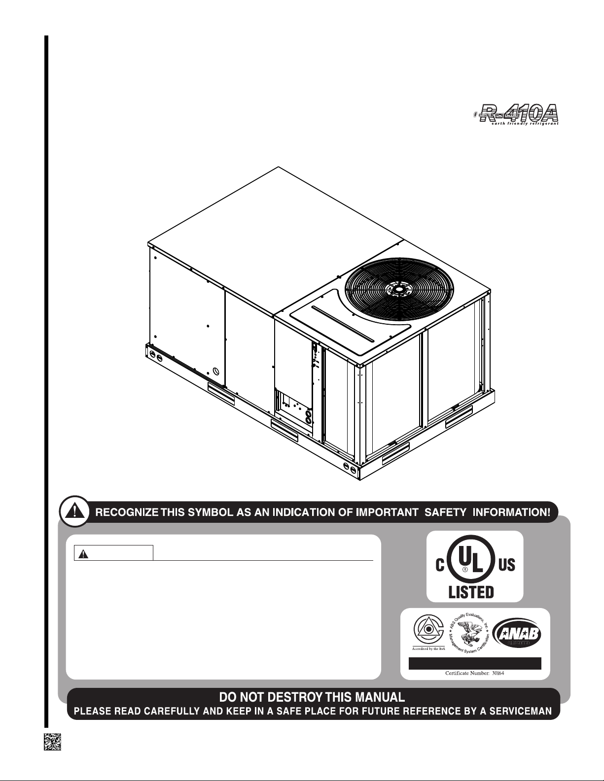
FOR PACKAGE AIR CONDITIONERS FEATURING
INDUSTRY STANDARD R410A REFRIGERANT
RLKN-B073 (6 TON) SERIES
[ ] INDICATES METRIC CONVERSIONS
92-23577-158-00
Page 2

I. TABLE OF CONTENTS
I. Table of Contents .................................................................................2
II. Introduction...........................................................................................3
III. Checking Product Received .................................................................3
IV. Equipment Protection ...........................................................................3
V. Specifications .......................................................................................3
A. General............................................................................................3
B. Major Components ..........................................................................4
C. R-410A Refrigerant..........................................................................4
1. Specification of R-410A...............................................................4
2. Quick Reference Guide for R-410A ............................................4
3. Evaporator Coil / TXV..................................................................4
4. Tools Required For Installing & Servicing
R-410A Models........................................................................4
Unit Dimensions ..............................................................................5
VI. General Data.....................................................................................8-9
VIII. Installation ..........................................................................................10
A. General..........................................................................................10
1. Pre-Installation Check Points ....................................................10
2. Location.....................................................................................10
B. Outside Slab Installation................................................................10
C. Clearances ....................................................................................12
D. Rooftop Installation........................................................................12
IX. Ductwork.............................................................................................12
X. Filters..................................................................................................13
XI. Conversion Procedure........................................................................13
XII. Condensate Drain ..............................................................................13
XIII. Electrical Wiring..................................................................................14
A. Power Wiring .................................................................................14
B. Special Instructions for Power
Wiring with Aluminum Conductors ............................................14
C. Control Wiring................................................................................15
D. Internal Wiring ...............................................................................15
E. Grounding......................................................................................15
F. Thermostat ....................................................................................16
XIV. Electrical Data ....................................................................................17
XV. Electric Heater Kits.............................................................................18
XVI. Airflow Performance ...........................................................................20
XVII. Indoor Air Flow Data...........................................................................21
XVIII. Crankcase Heat..................................................................................21
XIX. Pre-Start Check..................................................................................21
XX. Startup................................................................................................21
XXI. Operation............................................................................................22
XXII. Auxiliary Heat .....................................................................................22
XXIII. Replacement Parts.............................................................................22
XXIV. Charge Information.............................................................................22
XXV. Troubleshooting ..................................................................................22
XXVI. Wiring Diagrams .................................................................................22
2
Page 3
!
sWARNING
PROPOSITION 65: THIS APPLIANCE
CONTAINS FIBERGLASS INSULATION. RESPIRABLE PARTICLES OF
IBERGLASS ARE KNOWN TO THE
F
STATE OF CALIFORNIA TO CAUSE
CANCER.
!
sWARNING
THE MANUFACTURER’S WARRANTY
DOES NOT COVER ANY DAMAGE OR
DEFECT TO THE AIR CONDITIONER
CAUSED BY THE ATTACHMENT OR
USE OF ANY COMPONENTS, ACCESSORIES OR DEVICES (OTHER THAN
THOSE AUTHORIZED BY THE MANUFACTURER) INTO, ONTO OR IN CONJUNCTION WITH THE AIR CONDITIONER. YOU SHOULD BE AWARE
THAT THE USE OF UNAUTHORIZED
COMPONENTS, ACCESSORIES OR
DEVICES MAY ADVERSELY AFFECT
THE OPERATION OF THE AIR CONDITIONER AND MAY ALSO ENDANGER
LIFE AND PROPERTY. THE MANUFACTURER DISCLAIMS ANY
RESPONSIBILITY FOR SUCH LOSS
OR INJURY RESULTING FROM THE
USE OF SUCH UNAUTHORIZED COMPONENTS, ACCESSORIES OR
DEVICES.
!
sWARNING
DISCONNECT ALL POWER TO THE
UNIT BEFORE STARTING MAINTENANCE. FAILURE TO DO SO CAN
RESULT IN SEVERE ELECTRICAL
SHOCK OR DEATH.
II. INTRODUCTION
This booklet contains the installation and operating instructions for your self-contained
air conditioner. There are a few precautions that should be taken to derive maximum
atisfaction from it. Improper installation can result in unsatisfactory operation or dan-
s
gerous conditions.
Read this booklet and any instructions packaged with separate equipment required to
make up the system prior to installation. Give this booklet to the owner and explain its
provisions. The owner should retain this booklet for future reference.
III. CHECKING PRODUCT RECEIVED
Upon receiving the unit, inspect it for any damage from shipment. Claims for damage,
either shipping or concealed, should be filed immediately with the shipping company.
Check the unit model number, electrical characteristics, and accessories to determine
if they are correct.
IV. EQUIPMENT PROTECTION FROM THE
IV. ENVIRONMENT
The metal parts of this unit may be subject to rust or deterioration in adverse environmental conditions. This oxidation could shorten the equipment’s useful life. Salt spray,
fog or mist in seacoast areas, sulphur or chlorine from lawn watering systems, and various chemical contaminants from industries such as paper mills and petroleum refineries are especially corrosive.
If the unit is to be installed in an area where contaminants are likely to be a problem, special attention should be given to the equipment location and exposure.
1. Avoid having lawn sprinkler heads spray direction on the unit cabinet.
2. In coastal areas, locate the unit on the side of the building away from the waterfront.
3. Shielding provided by a fence or shrubs may give some protection.
Regular maintenance will reduce the buildup of contaminents and help to protect the unit’s finish.
1. Frequent washing of the cabinet, fan blade and coil with fresh water will remove
most of the salt or other contaminants that build up on the unit.
2. Regular cleaning and waxing of the cabinet with a good automobile polish will provide some protection.
3. A good liquid cleaner may be used several times a year to remove matter that will
not wash off with water.
Several different types of protective coatings are offered in some areas. These coatings may provide some benefit, but the effectiveness of such coating materials cannot
be verified by the equipment manufacturer.
The best protection is frequent cleaning, maintenance and minimal exposure to
contaminants.
V. SPECIFICATIONS
A. GENERAL
The Combination Electric Cooling Rooftop with optional electric heat is available in
cooling capacity of 6 nominal tons. Units are convertible from bottom supply and return
to side supply and return by relocation of supply and return air access panels. See
cover installation detail.
The units are weatherized for mounting outside of the building.
3
Page 4
B. MAJOR COMPONENTS
The unit includes a hermetically-sealed refrigerating system (consisting of a scroll
compressor, condenser coil, evaporator coil with thermostatic expansion valve), a circulation air blower, a condenser fan, and all necessary internal electrical wiring. The
cooling system of these units is factory-evacuated, charged with R-410A refrigerant
and performance tested. Refrigerant amount and type are indicated on rating plate.
C. R-410A REFRIGERANT
ll units are factory charged with R-410A refrigerant.
A
1. Specification of R-410A:
Application: R-410A is not a drop-in replacement for R-22; equipment designs
must accommodate its higher pressures. It cannot be retrofitted into R-22 units.
Pressure: The pressure of R-410A is approximately 60% (1.6 times) greater than
-22.Recovery and recycle equipment, pumps, hoses and the like need to have
R
design pressure ratings appropriate for R-410A. Manifold sets need to range up to 800
psig high-side and 250 psig low-side with a 550 psig low-side retard. Hoses need to
have a service pressure rating of 800 psig. Recovery cylinders need to have a 400
psig service pressure rating. DOT 4BA400 or DOT BW400.
Combustibility: At pressures above 1 atmosphere, mixture of R-410A and air can
become combustible. R-410A and air should never be mixed in tanks or supply
lines, or be allowed to accumulate in storage tanks. Leak checking should never
be done with a mixture of R-410A and air. Leak checking can be performed safely
with nitrogen or a mixture of R-410A and nitrogen.
2. Quick Reference Guide For R-410A
• R-410A refrigerant operates at approximately 60% higher pressure (1.6 times) than
R-22. Ensure that servicing equipment is designed to operate with R-410A.
• R-410A refrigerant cylinders are pink.
• R-410A, as with other HFC’s is only compatible with POE oils.
• Vacuum pumps will not remove moisture from POE oil.
• R-410A systems are to be charged with liquid refrigerants. Prior to March 1999, R410A refrigerant cylinders had a dip tube. These cylinders should be kept upright
for equipment charging. Post March 1999 cylinders do not have a dip tube and
should be inverted to ensure liquid charging of the equipment.
• Do not install a suction line filter drier in the liquid line.
• A liquid line filter drier is standard on every unit.
• Desiccant (drying agent) must be compatible for POE oils and R-410A
3. Evaporator Coil / TXV
The thermostatic expansion valve is specifically designed to operate with R-410A.
4. Tools Required For Installing & Servicing R-410A Models
Manifold Sets:
-Up to 800 PSIG High side
-Up to 250 PSIG Low Side
-550 PSIG Low Side Retard
Manifold Hoses:
-Service Pressure Rating of 800 PSIG
Recovery Cylinders:
-400 PSIG Pressure Rating
-Dept. of Transportation 4BA400 or BW400
!
sCAUTION
R-410A systems operate at higher pressures than R-22 systems. Do not use R-22
service equipment or components on R-410A equipment.
4
Page 5
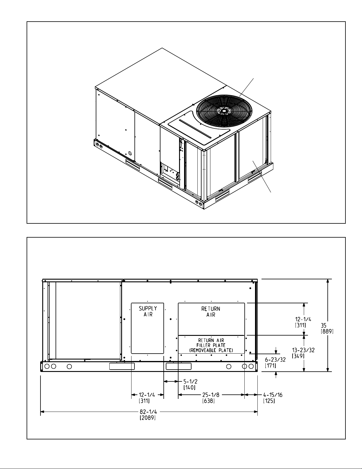
FIGURE 1
6 TON MODEL
OUTDOOR
FAN
OUTDOOR
COIL
FIGURE 2
BACK VIEW
[ ] Designates Metric Conversion
ST-A1143
5
Page 6
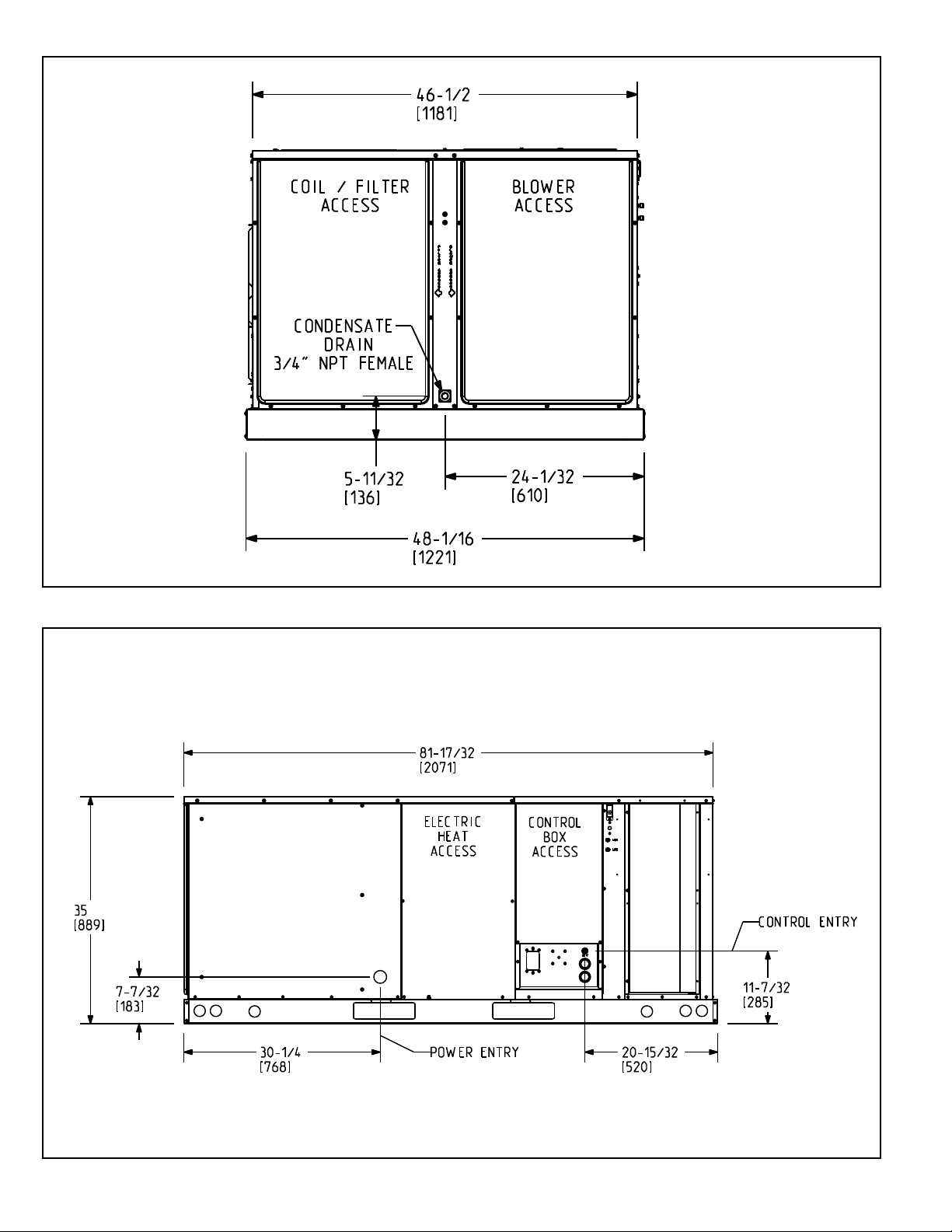
FIGURE 3
SIDE VIEW
[ ] Designates Metric Conversion
FIGURE 4
FRONT VIEW
T-A1143
S
[ ] Designates Metric Conversion
6
ST-A1143
Page 7
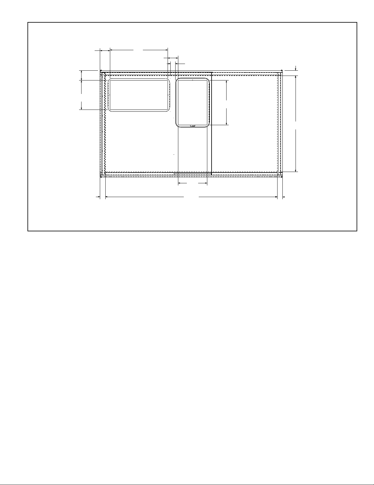
FIGURE 5
2-5/32
[55]
4-5/8
[118]
26
[660]
4.502
[114]
13-1/8
[333]
4
-1/2
[114]
13-1/8
[333]
77-15/32
[1968]
20
[508]
2-3/8
[60]
43-7/32
[1098]
2-3/8
[60]
2-3/8
[60]
RETURN
AIR
SUPPLY
AIR
[ ] DESIGNATES METRIC CONVERSIONS
TOP VIEW
ST-A1143
TOP VIEW
7
Page 8

VI. GENERAL DATA - RLKN MODELS
M
D370BLD370BMC370BLC370BseireS -NKLR ledoM
Coolin
g
Performance Continued ->
Compresso
r
Outdoor Sound Ratin
g (
d
B
)
3
8383838
Outdoor Coil - Fin T
y
pe Louvered Louvered Louvered Louvered
Tube T
ype
M
icroChannel MicroChannel MicroChannel MicroChannel
MicroChannel Depth in. [mm
]
0
.7 [17.8] 0.7 [17.8] 0.7 [17.8] 0.7 [17.8]
Face Area sq. ft. [sq. m
]
16.4 [1.52]16.4 [1.52] 16.4 [1.52] 16.4 [1.52]
]
9[ 32 / 1]9[ 32 / 1]9[ 32 / 1]9[ 32 / 1]mcPF[ IPF / swoR
Indoor Coil - Fin T
y
p
e Louvered Louvered Louvered Louvered
Tube T
ype
MicroChannel MicroChannel MicroChannel MicroChannel
MicroChannel Depth in. [mm
]
1.3 [33] 1.3 [33] 1.3 [33] 1.3 [33]
Face Area sq. ft. [sq. m
]
6 [0.56] 6 [0.56] 6 [0.56] 6 [0.56]
]9[ 22 / 1]9[ 22 / 1]9[ 22 / 1]9[ 22 / 1]mcPF[ IPF / swoR
Refri
g
evlaV XTevlaV XTevlaV XTevlaV XTlortnoC tnare
Drain Connection No./Size in. [mm
1/1 [25.4] 1/1 [25.4] 1/1 [25.4] 1/1 [25.4]
Outdoor Fan - T
y
pe Propelle
r
Propelle
r
Propelle
r
Propelle
r
No. Used/Diameter in. [mm
]
1/24 [609.6] 1/24 [609.6] 1/24 [609.6] 1/24 [609.6]
Drive T
y
pe/No. Speed
s
Direct/1 Direct/1 Direct/1 Direct/1
PH 2/1 ta 1PH 2/1 ta 1PH 2/1 ta 1PH 2/1 ta 1PH/srotoM .oN
5701570157015701MPR rotoM
Indoor Fan - T
y
pe FC Centrifugal FC Centrifugal FC Centrifugal FC Centrifugal
No. Used/Diameter in. [mm
]
1/11x10 [279×254] 1/11×10 [279×254] 1/11×10 [279×254]
Drive T
y
tleBep
(Adj
ustable
)
Belt(Adjustable
)
Belt(Adjustable
)
Belt(Adjustable
)
niSsdeepS .oN
g
le Single Single Single
1111srotoM .oN
2 2 2 2PH rotoM
5271527152715271MPR rotoM
Motor Frame Siz
e
65656565
Filter - T
y
pe Disposabl
e
Disposabl
e
Disposabl
e
Disposabl
e
seYseYseYseYdehsinruF
(No.) Size Recommended in. [mm × mm × mm]
Refri
g
erant Charge Oz. [g] 67 [1899]67 [1899] 67 [1899] 67 [1899]
Wei
g
hts
Net Wei
g
ht lbs. [k
g]
569 [258]574 [260] 569 [258] 574 [260]
Ship Weight lbs. [kg
]
576 [261]579 [263] 576 [261] 579 [263]
1
4
]
]5.02[ 000,07]5.02[ 000,07]5.02[ 000,07]5.02[ 000,07]Wk[ utB yticapaC gnilooC ssorG
EER/IEER
11.2/NA/ 11.2/NA 11.2/NA/ 11.2/NA//
Nominal CFM/AHRI Rated CFM [L/s] 2400/2100 [1133/991] 2400/2100 [1133/991] 2400/2100 [1133/991] 2400/2100 [1133/991]
AHRI Net Cooling Capacity Btu [kW] 68,000 [19.92] 68,000 [19.92] 68,000 [19.92] 68,000 [19.92]
]84.31[ 000,64]84.31[ 000,64]84.31[ 000,64]84.31[ 000,64]Wk[ utB yticapaC elbisneS teN
]
54.6[ 000,22]54.6[ 000,22]54.6[ 000,22]54.6[ 000,22]Wk[ utB yticapaC tnetaL teN
IEER
9.219.219.219.21
70.670.670.670.6Wk rewoP metsyS teN
2
l (2-Stage)lorcS/1l (2-Stage)lorcS/1l (2-Stage) lorcS/1l (2-Stage)lorcS/1epyT/.oN
]2891[ 0024]2891[ 0024]2891[ 0024]2891[ 0024]s/L[ MFC
(4)2×16×16 [51×406×406]
(4)2×16×16 [51×406×406] (4)2×16×16 [51×406×406]
(4)2×16×16 [51×406×406]
1/11×10 [279×254]
NOMINAL SIZES 6 TON [21.1 kW]
[ ] Designates Metric Conversions
NOTES:
1. Cooling Performance is rated at 95° F ambient, 80° F entering dry bulb, 67° F entering wet bulb. Gross capacity does not include the effect of fan motor heat. AHRI rated capacity is net and
includes the effect of fan motor heat. Units are suitable for operation to ±20% of nominal cfm. Units are certified in accordance with the Unitary Large Equipment certification program, which is
based on AHRI Standard 340/360.
2. EER and IEER are rated at AHRI conditions and in accordance with DOE test procedures and AHRI Standard 340/360.
3. Heating Performance limit settings and rating data were established and approved under laboratory test conditions using American National Standard Institute standards. Ratings shown are for
elevations up to 2000 feet. For elevations above 2000 feet, ratings should be reduced at the rate of 4% for each 1000 feet above sea level.
4. Outdoor Sound Rating shown is tested in accordance with AHRI Standard 270.
8
Page 9

GENERAL DATA - RLKN MODELS
MY370BLY370BseireS -NKLR ledoM
Coolin
g
Performance
Gross Coolin
g
Capacit
y
Btu [kW
]
7
0,000 [20.5]70,000 [20.5]
EER/IEER 11.2/N
A
1
1.2/N
A
Nominal CFM/AHRI Rated CFM [L/s
]
2400/2100 [1133/991
]
2400/2100 [1133/991
]
AHRI Net Coolin
g
Capacit
y
Btu [kW
]
6
8,000 [19.92]68,000 [19.92]
Net Sensible Capacit
y
Btu [kW
]
4
6,000 [13.48]46,000 [13.48]
Net Latent Capacit
y
Btu [kW
]
2
2,000 [6.45]22,000 [6.45]
IEER 12.9 12.9
Net S
y
s
tem Power k
W
6
.07 6.07
Compresso
r
No./T
y
l (2-Stage)lorcS/1l (2-Stage)lorcS/1ep
Outdoor Sound Ratin
g (
d
B
)
3
838
Outdoor Coil - Fin T
y
pe Louvered Louvered
Tube T
ype
MicroChannel MicroChannel
MicroChannel Depth in. [mm
]
0
.7 [17.8] 0.7 [17.8]
Face Area sq. ft. [sq. m
]
1
6.4 [1.52]16.4 [1.52]
]
9[ 32 / 1]9[ 32 / 1]mcPF[ IPF / swoR
Indoor Coil - Fin T
y
p
e Louvered Louvered
Tube T
ype
M
icroChannel MicroChannel
MicroChannel Depth in. [mm
]
1
.3 [33] 1.3 [33]
Face Area sq. ft. [sq. m
]
6 [0.56] 6 [0.56]
]9[ 22 / 1]9[ 22 / 1]mcPF[ IPF / swoR
Refri
g
evlaV XTevlaV XTlortnoC tnare
Drain Connection No./Size in. [mm
]
1/1 [25.4] 1/1 [25.4]
Outdoor Fan - T
y
pe Propelle
r
Propelle
r
No. Used/Diameter in. [mm
]
1/24 [609.6] 1/24 [609.6]
Drive T
y
pe/No. Speed
s
Direct/1 Direct/1
]2891[ 0024]2891[ 0024]s/L[ MFC
PH 2/1 ta 1PH 2/1 ta 1PH/srotoM .oN
57015701MPR rotoM
Indoor Fan - T
y
pe FC Centrifugal FC Centrifugal
No. Used/Diameter in. [mm
]
1/11×10 [279×254] 1/11×10 [279×254]
Drive T
y
tleBep
(Adj
ustable
)
Belt(Adjustable
)
niSsdeepS .oN
g
le Single
11srotoM .oN
2/1 12/1 1PH rotoM
52715271MPR rotoM
Motor Frame Siz
e
6565
Filter - T
y
pe Disposabl
e
Disposabl
e
seYseYdehsinruF
(
No.) Size Recommended in. [mm × mm × mm] (4)2×16×16 [51×406×406]
Refri
g
erant Charge Oz. [g] 67 [1899]67 [1899]
Wei
g
hts
Net Wei
g
ht lbs. [k
g]
569 [258]574 [260]
Ship Weight lbs. [kg
]
576 [261]579 [263]
1
2
4
(4)2×16×16 [51×406×406]
NOMINAL SIZES 6 TON [21.1 kW]
[ ] Designates Metric Conversions
NOTES:
1. Cooling Performance is rated at 95° F ambient, 80° F entering dry bulb, 67° F entering wet bulb. Gross capacity does not include the effect of fan motor heat. AHRI rated capacity is net and
includes the effect of fan motor heat. Units are suitable for operation to ±20% of nominal cfm. Units are certified in accordance with the Unitary Large Equipment certification program, which is
based on AHRI Standard 340/360.
2. EER and IEER are rated at AHRI conditions and in accordance with DOE test procedures and AHRI Standard 340/360.
3. Heating Performance limit settings and rating data were established and approved under laboratory test conditions using American National Standard Institute standards. Ratings shown are for
elevations up to 2000 feet. For elevations above 2000 feet, ratings should be reduced at the rate of 4% for each 1000 feet above sea level.
4. Outdoor Sound Rating shown is tested in accordance with AHRI Standard 270.
9
Page 10

VIII. INSTALLATION
36“
60“
48“
VERTICAL
CLEARANCE
18“
12“
A. GENERAL
1. PRE-INSTALLATION CHECK-POINTS
Before attempting any installation, the following points should be carefully con-
sidered:
a. Structural strength of supporting members.
(rooftop installation)
b. Clearances and provision for servicing.
c. Power supply and wiring.
d. Air duct connections.
e. Drain facilities and connections.
f. Location for minimum noise.
2. LOCATION
These units are designed for outdoor installations. They can be mounted on a
slab or rooftop. They are not to be installed within any part of a structure such
as an attic, crawl space, closet, or any other place where condenser air flow is
estricted or other than outdoor ambient conditions prevail. Since the application
r
of the units is of the outdoor type, it is important to consult your local code
authorities at the time the first installation is made.
B. OUTSIDE SLAB INSTALLATION (Typical outdoor slab installations are shown in
Figures 6 and 7.)
1. Select a location where external water drainage cannot collect around the unit.
2. Provide a level concrete slab extending 3" beyond all four sides of the unit. The
slab should be sufficient above grade to prevent ground water from entering the
unit.
IMPORTANT: To prevent transmission of noise or vibration, slab should not be connected to building structure.
3. The location of the unit should be such as to provide proper access for inspec-
tion and servicing.
4. Locate unit where operating sounds will not disturb owner or neighbors.
5. Locate unit so roof runoff water does not pour directly on the unit. Provide gutter
or other shielding at roof level. Do not locate unit in an area where excessive
snow drifting may occur or accumulate.
FIGURE 6
PACKAGED AIR CONDITIONER
OUTSIDE SLAB INSTALLATION, BASEMENT OR
CRAWL SPACE DISTRIBUTION SYSTEM
FIGURE 7
PACKAGED AIR CONDITIONER
OUTSIDE SLAB INSTALLATION, CLOSET
DISTRIBUTION SYSTEM. SLAB FLOOR CONSTRUCTION
10
ST-A1142-13
ST-A1142-12
Page 11

FIGURE 8
PACKAGED AIR CONDITIONER
IGGING FOR LIFTING
R
3
9
A
B
C
E
N
T
E
GR
OF
R
A
V
I
T
Y
2
6
-
1
/
8
FIGURE 9
PACKAGED AIR CONDITIONER
ROOFCURB INSTALLATION
D
CORNER WEIGHTS BY PERCENTAGE
A B C D
C
ILL I296
23% 29% 21% 27%
ILL I300
ILL I301
11
Page 12

!
sWARNING
DO NOT, UNDER ANY CIRCUMSTANCES, CONNECT RETURN DUCTWORK TO ANY OTHER HEAT PRO-
UCING DEVICE SUCH AS A FIRE-
D
PLACE INSERT, STOVE, ETC.
UNAUTHORIZED USE OF SUCH
DEVICES MAY RESULT IN FIRE, CARBON MONOXIDE POISONING, EXPLOSION, PROPERTY DAMAGE, SEVERE
PERSONAL INJURY OR DEATH.
C. CLEARANCES
The following minimum clearances must be observed for proper unit performance
nd serviceability.
a
1. Unit is design certified for application on combustible flooring with 0" minimum
clearance.
2. See Figure 6 for illustration of minimum installation-service clearances.
D. ROOFTOP INSTALLATION
1. Before locating the unit on the roof, make sure that the strength of the roof and
beams is adequate at that point to support the weight involved. (See specification sheet for weight of unit.) This is very important and user’s responsibility.
2. For rigging and roofcurb details, see Figures 8 and 9. Use field-furnished
spreaders.
3. For roofcurb assembly, see Roofcurb Installation Instructions.
4. If the roofcurb is not used, provisions for disposing of condensate water runoff
must be provided.
5. The unit should be placed on a solid and level roofcurb or platform of adequate
strength. See Figure 10.
6. The location of the unit on the roof should be such as to provide proper access
for inspection and servicing.
IMPORTANT: If unit will not be put into service immediately, cover supply and return
openings to prevent excessive condensation.
FIGURE 10
ACKAGED AIR CONDITIONER
P
FLAT ROOFTOP INSTALLATION, ATTIC OR DROP CEILING DISTRIBUTION
YSTEM. MOUNTED ON ROOFCURB. CURB MUST BE LEVEL
S
12
ST-A1142-10
IX. DUCTWORK
Ductwork should be fabricated by the installing contractor in accordance with local
codes and NFPA90A. Industry manuals may be used as a guide when sizing and
designing the duct system – contact Air Conditioning Contractors of America, 1513 16th
St. N.W., Washington, D.C. 20036.
The unit should be placed as close to the space to be air conditioned as possible allowing clearance dimensions as indicated. Ducts should be run as directly as possible to
supply and return outlets. Use of non-flammable waterproof flexible connectors on
both supply and return connections at the unit to reduce noise transmission is recommended.
It is preferable to install the unit on the roof of the structure if the registers or diffusers
are located on the wall or in the ceiling. A slab installation could be considered when
the registers are low on a wall or in the floor.
On ductwork exposed to outside air conditions of temperature and humidity, use a minimum of 2" of insulation and a vapor barrier. Distribution system in attic, furred space
or crawl space should be insulated with at least 2" of insulation with vapor barrier. One-
Page 13

half to 1" thickness of insulation is usually sufficient for ductwork inside the air condi-
ioned space.
t
Balancing dampers should be provided for each branch duct in the supply system.
Ductwork should be properly supported from the structure.
When installing ductwork, consider the following items:
1. Noncombustible flexible connectors should be used between ductwork and unit to
reduce noise and vibration transmission into the ductwork.
2. When auxiliary heaters are installed, use noncombustible flexible connectors and
clearance to combustible material of 0" for the first 3 feet of discharge duct.
Clearance to unit top and side is 0".
X. FILTERS
This unit is provided with disposable filters. When replacing filters, ensure they are
inserted fully to the back to prevent bypass.
XI. CONVERSION PROCEDURE
DOWNFLOW TO HORIZONTAL
1. Remove the screws and covers from the outside of the supply and return sections.
2. Install the covers in the bottom supply and return openings with the painted side
up. See Figure 11. Use the existing gasket to seal the covers.
FIGURE 11
COVER GASKET DETAIL
ILL I631
3. Secure the supply cover to the base of the unit with 1 screw, engaging prepunched
tab in unit base.
4. Secure the return cover to the base of the unit with screws, engaging prepunched
holes in the unit base.
XII. CONDENSATE DRAIN
IMPORTANT: Install a condensate trap to ensure proper condensate drainage.
See Figure 12.
The condensate drain pan has a threaded female 3/4 inch NPT connection. Consult
local codes or ordinances for specific requirements of condensate drain piping and
disposal.
• Use a thin layer of Teflon tape or paste on drain pan connections and install only
hand tight.
• Do not over tighten drain pan connections as damage to the drain pan may occur.
• Drain line MUST NOT block service access panels.
• Drain line must be no smaller than drain pan outlet and adequately sized to
accommodate the condensate discharge from the unit.
• Drain line should slope away from unit a minimum of 1/8” per foot to ensure proper
drainage.
• Drain line must be routed to an acceptable drain or outdoors in accordance with
local codes.
• Do not connect condensate drain line to a closed sewer pipe.
• Drain line may need insulation or freeze protection in certain applications.
13
Page 14

IGURE 12
F
ONDENSATE DRAIN
C
DO NOT OVERTIGHTEN DRAIN FITTING
XIII. ELECTRICAL WIRING
Field wiring must comply with the National Electrical Code* and local ordinances that
may apply.
*C.E.C. in Canada
A. POWER WIRING
1. It is important that proper electrical power is available at the unit. Voltage should
not vary more than 10% from that stamped on the unit rating plate. On three
phase units, phases must be balanced within 3%.
2. Install a branch circuit disconnect within sight of the unit and of adequate size.
3. For branch circuit wiring (main power supply to unit disconnect), the minimum
wire size can be determined using the circuit ampacity found on the unit nameplate.
4. This unit incorporates single point electrical connection for unit and electric heat
accessory.
5. Power wiring must be run in grounded rain-tight conduit. Connect the power field
wiring as follows:
a. NO ELECTRIC HEAT - Connect the field wires directly to the contactor pigtail
b. WITH ELECTRIC HEAT - Connect the field wires to the terminal block on the
NOTE: For field installation of a heater kit, follow the instructions provided with the
heater kit.
6. The pigtail wires in the electric heat access area are factory wired to the contac-
7. DO NOT connect aluminum field wires to electric heat kit power input terminals.
in the electric heat access area. Connect ground wire to ground lug.
electric heater kit in the electric heat access area. Connect the unit contactor
pigtails to the appropriate fuse block on the heater kit. Connect the ground
wire to the ground lug on the heater kit.
tor in the control box.
14
TABLE E. WIRE SIZES
AWG Copper AWG Aluminum Connector Type and Size
Wire Size Wire Size (or equivalent)
#12 #10 T&B Wire Nut PT2
#10 #8 T&B Wire Nut PT3
#8 #6 Ilsco Split Bolt AK-6
#6 #4 Ilsco Split Bolt AK-4
#4 #2 Ilsco Split Bolt AK-2
#3 #1 Ilsco Split Bolt AK-1/0
#2 #0 Ilsco Split Bolt AK-1/0
#1 #00 Ilsco Split Bolt AK-2/0
#0 #000 Ilsco Split Bolt AK-4/0
B. SPECIAL INSTRUCTIONS FOR POWER WIRING WITH ALUMINUM
CONDUCTORS.
1. Select the equivalent aluminum wire size from the tabulation below:
2. Attach a length (6" or more) of recommended size copper wire to the unit terminals L1 and L3 for single phase, L1, L2, L3 for three phase.
Page 15

!
sWARNING
THE UNIT MUST BE PERMANENTLY
GROUNDED. A GROUNDING LUG IS
PROVIDED IN THE ELECTRIC HEAT
IT ACCESS AREA FOR A GROUND
K
WIRE. FAILURE TO GROUND THIS
UNIT CAN RESULT IN FIRE OR ELECTRICAL SHOCK CAUSING PROPERTY DAMAGE, SEVERE PERSONAL IN JURY OR DEATH.
3. Splice copper wire pigtails to aluminum wire with U.L. recognized connectors for
copper-aluminum splices. Follow these instructions very carefully to make a
ositive and lasting connection;
p
a. Strip insulation from aluminum conductor.
b. Coat the stripped end of the aluminum wire with the recommended inhibitor
c. Clean and recoat aluminum conductor with inhibitor.
d. Make the splice using the above listed wire nuts or split bolt connectors.
e. Coat the entire connection with inhibitor and wrap with electrical insulating
WARRANTY MAY NOT APPLY IF CONNECTIONS ARE NOT MADE PER INSTRUC-
IONS
T
and wire brush aluminum surface through inhibitor. Inhibitors: Brundy, Pentex
“A”; Alcoa, No. 2EJC; T&B KPOR Shield.
tape.
C. CONTROL WIRING (Class II)
1. Low voltage wiring should not be run in conduit with power wiring.
2. Control wiring is routed through the 7/8" hole adjacent to the compressor access
panel. See Figure 13. Use a minimum #18 AWG thermostat wire. For wire
lengths exceeding 50', use #16 AWG thermostat wire. The low voltage wires are
connected to the unit pigtails which are supplied with the unit in the low voltage
connection box located below the unit control box.
3. Figure 13 shows representative low voltage connection diagrams. Read your
thermostat installation instructions for any special requirements for your specific
thermostat.
NOTE — Units installed in Canada require that an outdoor thermostat (30,000
min. cycles of endurance) be installed and be wired with C.E.C. Class I wiring.
D. INTERNAL WIRING
1. A diagram of the internal wiring of this unit is located on the inside of the compressor access panel. If any of the original wire as supplied with the appliance
must be replaced, the wire gauge and insulation must be the same as original
wiring.
FIGURE 13
LOW VOLTAGE CONNECTIONS DIAGRAMS
THERMOSTAT
SUB-BASE
R
W
G
Y
E. GROUNDING
GROUNDING MAY BE ACCOMPLISHED BY GROUNDING THE POWER LINE
CONDUIT TO THE UNIT. MAKE SURE THE CONDUIT NUT LOCKING TEETH
HAVE PIERCED THE INSULATING PAINT FILM OF THE SIDE PANEL.
STANDARD CONTROL WIRING
UNIT CONTROLS
WIRE PIGTAILS
RED
BLACK
GRAY
YELLOW
Y2
C
ORANGE
BROWN
15
Page 16

BRANCH
C
IRCUIT
DISCONNECT
POWER
CONTROL
2
4
V
FIGURE 14
RECOMMENDED LOCATION OF BRANCH CIRCUIT DISCONNECT
ST-A1142-11
F. THERMOSTAT
The thermostat should be mounted on an inside wall about five feet above the floor
in a location where it will not be affected by unconditioned air, sun, or drafts from
open doors or other sources. READ installation instructions in thermostat package
CAREFULLY because each has some different wiring requirements.
16
Page 17

XIV. ELECTRICAL DATA
B073CL B073CM B073DL B073DM B073YL B073YM
U
nit Operating Voltage Range 187-253 187-253 414-506 414-506 518-632 518-632
V
olts 208/230 208/230 460 460 575 575
Phase333333
H
z606060606060
Minimum Circuit Ampacity 31 31 16 16 11 11
Minimum Overcurrent Protection
D
evice Size
35 35 20201515
M
aximum Overcurrent Protection
D
evice Size
4
5 45 20201515
No.111111
V
olts 208/230 208/230 460 460 575 575
Phase333333
RPM 3450 3450 3450 3450 3450 3450
H
P, Compressor 1555555
Amps (RLA), Comp. 1 17.6 17.6 8.5 8.5 6.3 6.3
Amps (LRA), Comp. 1 136 136 66.1 66.1 55.3 55.3
HP, Compressor 2
Amps (RLA), Comp. 2
Amps (LRA), Comp. 2
No.111111
Volts 208/230 208/230 460 460 575 575
Phase111111
HP 1/2 1/2 1/2 1/2 1/2 1/2
Amps (FLA, each) 2.3 2.3 1.5 1.5 1.0 1.0
Amps (LRA, each) 5.6 5.6 3.1 3.1 2.2 2.2
No.111111
Volts 208/230 208/230 460 460 575 575
Phase333333
HP 2 2 2 2 1 1/2 1 1/2
Amps (FLA, each) 6.2 6.2 3.0 3.0 2.1 2.1
Amps (LRA, each) 47 47 24 24 13.1 13.1
Evaporator Fan
E
LECTRICAL DATA - RLKN- SERIES
Unit InformationCompressor MotorCondenser Motor
17
Page 18

XV. ELECTRIC HEATER KITS
RLKN-B073CL No Heat----- ----- ----- ----- 31/31 45 45 ----- ----- 31/31 45 45
A
06C 1 4.2/5.614.33/19.111.7/13.5 31/31 45 45 15/17 15/20 31/31 45 45
A
10C 1 7.2/9.624.56/32.7520/23.1 31/37 45 45 25/29 25/30 31/31 45 45
A15C 1 10.8/14.4 36.84/49.13 30.1/34.7 46/52 50 60 38/44 40/45 31/31 45 45
A
20C 1 14.4/19.2 49.13/65.5 40/46.3 58/66 60 70 50/58 50/60 31/31 45 45
A
24C 1 18/24 61.41/81.88 50/57.7 71/80 80 80 63/73 70/80 31/31 45 45
RLKN-B073CM No Heat----- ----- ----- ----- 31/31 45 45 ----- ----- 31/31 45 45
A06C 1 4.2/5.614.33/19.111.7/13.5 31/31 45 45 15/17 15/20 31/31 45 45
A10C 1 7.2/9.624.56/32.7520/23.1 31/37 45 45 25/29 25/30 31/31 45 45
A15C 1 10.8/14.4 36.84/49.13 30.1/34.7 46/52 50 60 38/44 40/45 31/31 45 45
A
20C 1 14.4/19.2 49.13/65.5 40/46.3 58/66 60 70 50/58 50/60 31/31 45 45
A24C 1 18/24 61.41/81.88 50/57.7 71/80 80 80 63/73 70/80 31/31 45 45
RLKN-B073DL No Heat----- ----- ----- ----- 16 20 ----- -----16 20
A06D 1 5.619.16.716 20 9 15 16 20
A10D 1 9.632.7511.6 19 20 15 15 16 20
A15D 1 14.4 49.13 17.4 26 30 22 25 16 20
A20D 1 19.2 65.5 23.3 33 35 30 30 16 20
A24D 1 24 81.88 28.9 40 40 37 40 16 20
RLKN-B073DM No Heat----- ----- ----- ----- 16 20 ----- ----- 16 20
A06D 1 5.619.16.716 20 9 15 16 20
A10D 1 9.632.7511.6 19 20 15 15 16 20
A15D 1 14.4 49.13 17.4 26 30 22 25 16 20
A20D 1 19.2 65.5 23.3 33 35 30 30 16 20
A24D 1 24 81.88 28.9 40 40 37 40 16 20
Rated Heater
kW @ 480 V
Heater
KBTU/Hr @
480 V
Heater
Amp. @ 480
V
Unit Min. Ckt.
Ampacity @
480 V
Max. Fuse
Size 480V
Min. Circuit
Ampacity
480V
480 V 480 V
Min. Ckt.
Ampacity
480V
480 VOLT, THREE PHASE, 60 HZ, AUXILIARY ELECTRIC HEATER KITS CHARACTERISTICS AND APPLICATION
tiK retaeH dna tinU htoB rof ylppuS rewoP etarapeStiK retaeH dna tinU htoB rof ylppuS rewoP elgniS
RHEEM Model Number
renoitidnoC riAtiK retaeHrenoitidnoC riAtiK retaeH
No. of
Sequence
Steps
Rated Heater
k
W @
208/240 V
Heater
K
BTU/Hr @
208/240 V
Heater
A
mp. @
208/240 V
Unit Min. Ckt.
A
mpacity @
208-240 V
Max. Fuse
Size
208/240V
Min. Circuit
Ampacity
208/240V
2
08 V 240 V 208 V 240 V
Min. Ckt.
Ampacity
208/240V
2
08/240 VOLT, THREE PHASE, 60 HZ, AUXILIARY ELECTRIC HEATER KITS CHARACTERISTICS AND APPLICATION
tiK retaeH dna tinU htoB rof ylppuS rewoP etarapeStiK retaeH dna tinU htoB rof ylppuS rewoP elgniS
RHEEM Model Number
r
enoitidnoC riAtiK retaeHrenoitidnoC riAtiK retaeH
No. of
Sequence
Steps
Rated Heater
kW @
2
08/240 V
Heater
KBTU/Hr @
2
08/240 V
Heater
Amp. @
2
08/240 V
Unit Min. Ckt.
Ampacity @
2
08-240 V
Max. Fuse
Size
2
08/240V
Min. Circuit
Ampacity
2
08/240V
Max. Over Current
P
rotective Device Size
208 V 240 V 208 V 240 V
Max. Over Current
P
rotective Device Size
Min. Ckt.
Ampacity
208/240V
208/240 VOLT, THREE PHASE, 60 HZ, AUXILIARY ELECTRIC HEATER KITS CHARACTERISTICS AND APPLICATION
t
iK retaeH dna tinU htoB rof ylppuS rewoP etarapeStiK retaeH dna tinU htoB rof ylppuS rewoP elgniS
RHEEM Model Number
renoitidnoC riAtiK retaeHrenoitidnoC riAtiK retaeH
R
XJJ- Heater
Kit Nominal
k
W
N
o. of
Sequence
S
teps
Max. Over Current
P
rotective Device Size
Max. Over Current
P
rotective Device Size
Max. Over Current
Protective Device Size
Max. Over Current
Protective Device Size
Max. Over Current
Protective Device Size
Max. Over Current
Protective Device Size
18
Page 19

80 80 63
45 45 ----- ----- 31
45 45 15
45 45 25
50 60 38
60 70 50
80 80 63
----- -----1
20 9 15
20 15
35 30
40 37
20 ----- -----1
20 9 15
20 15
35 30
40 37
R
LKN-B073YL No Heat----- ----- ----- ----- 11 15 ----- ----- 11 15
A
15Y 1 14.4 49.13 13.9 20 20 18 20 11 15
A20Y 1 19.2 65.5 18.8 27 30 24 25 11 15
A
24Y 1 24 81.88 23.1 32 35 29 30 11 15
RLKN-B073YM No Heat----- ----- ----- ----- 11 15 ----- ----- 11 15
A
15Y 1 14.4 49.13 13.9 20 20 18 20 11 15
A20Y 1 19.2 65.5 18.8 27 30 24 25 11 15
A
24Y 1 24 81.88 23.1 32 35 29 30 11 15
R
ated Heater
k
W @ 600 V
H
eater
KBTU/Hr @
600 V
H
eater
Amp. @ 600
V
U
nit Min. Ckt.
Ampacity @
600 V
Max. Fuse
Size 600V
Min. Circuit
Ampacity
600V
600 V 600 V
Min. Ckt.
Ampacity
600V
6
00 VOLT, THREE PHASE, 60 HZ, AUXILIARY ELECTRIC HEATER KITS CHARACTERISTICS AND APPLICATION
t
iK retaeH dna tinU htoB rof ylppuS rewoP etarapeStiK retaeH dna tinU htoB rof ylppuS rewoP elgniS
RHEEM Model Number
renoitidnoC riAtiK retaeHrenoitidnoC riAtiK retaeH
N
o. of
Sequence
Steps
Rated Heater
kW @ 600 V
Heater
KBTU/Hr @
600 V
Heater
A
mp. @ 600
V
Unit Min. Ckt.
A
mpacity @
6
00 V
Max. Fuse
Size 600V
Min. Circuit
A
mpacity
6
00V
600 V 600 V
Min. Ckt.
A
mpacity
6
00V
600 VOLT, THREE PHASE, 60 HZ, AUXILIARY ELECTRIC HEATER KITS CHARACTERISTICS AND APPLICATION
tiK retaeH dna tinU htoB rof ylppuS rewoP etarapeStiK retaeH dna tinU htoB rof ylppuS rewoP elgniS
R
HEEM Model Number
r
enoitidnoC riAtiK retaeHrenoitidnoC riAtiK retaeH
No. of
S
equence
S
teps
R
Max. Over Current
Protective Device Size
Max. Over Current
Protective Device Size
M
ax. Over Current
Protective Device Size
M
ax. Over Current
Protective Device Size
FIGURE 15
HEATER KIT INSTALLATION
ILL I312
19
Page 20

1000 1200 1400 1600 1800 2000 2200 2400 2600 2800
.035 .040 .060 .070 .085 .100 .110 120 .125 .130
.055 .060 .066 .072 .080 .086 .093 .100 .107 .115
.05 .06 .07 .08 .09 .10 .11 .12 .13 .15
NOTES:
4. BHP = WATTS X MOTOR EFF.
5. ADD COMPONENT RESISTANCE TO DUCT STATIC TO DETERMINE TOTAL E.S.P.
746
COMPONENT
RESISTANCE - INCHES WATER
WET COIL
DOWNFLOW
ECONOMIZER
STANDARD INDOOR AIRFLOW - CFM
COMPONENT AIR RESISTANCE
1. PERFORMANCE SHOWN WITH DRY COIL & STANDARD 1" FILTERS
2. STANDARD CFM @ .075 LBS./CU. FT.
3. MOTOR EFFICIENCY = 80%
R.A. DAMPER
1205
1230
1295
1380
1240
1255
—————
—————
1015
WATTS
RPM
1210
“M”
—
980
1150
1250
1330
WATTS
1180
RPM
1425
1205
1220
1230
1240
—
1525
1630
—
—
1255
1295
940
1180
1090
1260
WATTS
1150
RPM
890
WATTS
1120
RPM
850
WATTS
RPM
1090
800
WATTS
RPM
1050
760
WATTS
RPM
1010
720
WATTS
975
RPM
670
WATTS
1370
1175
1190
1205
1220
1130
1035
1220
1325
1145
1160
1180
1200
1160
1000
1060
1250
1120
1130
1145
1160
940
1100
1180
1025
1135
1120
1100
1085
900
960
1130
1045
1100
1050
1065
1080
840
920
1000
1060
1015
1030
1050
1065
800
860
930
1005
—
1470
1580
1665
—
1235
1250
1270
1430
1530
1635
1730
1220
1230
1240
1255
1355
1450
1580
1675
1185
1205
1225
1235
1335
1390
1505
1615
1175
1150
1200
1220
1215
1300
1425
1540
1185
1165
1135
1120
1155
1260
1350
1470
1110
1155
1135
1085
1110
1240
1295
1305
930
975
995
RPM
EXTERNAL STATIC PRESSURE – INCHES OF WATER
WATTS
RPM
WATTS
RPM
WATTS
RPM
1015
1035
650
750
820
880
960
895
930
955
980
1000
605
720
780
850
910
850
895
920
945
960
560
675
740
810
870
785
860
880
910
930
1125
1100
1055
1080
1140
1225
1335
1050
1025
1045
1065
1090
990
1175
1260
1085
990
1020
1040
1060
945
1105
1020
1200
950
980
1005
1030
XVI. BELT-DRIVE AIRFLOW PERFORMANCE 6 TON MODEL
—
625
680
750
830
900
975
1145
WATTS
—
815
840
—
600
—
775
———
———
650
810
L”
“
865
700
825
660
780
RPM
WATTS
RPM
WATTS
0.1 0.2 0.3 0.4 0.5 0.6 0.7 0.8 0.9 1.0 1.10 1.20 1.30 1.40 1.50
VOLTAGE 208-230, 460 & 575 V. - 3 PHASE
CAPACITY 6 TON
RPM
1060
890
920
945
975
1000
760
835
915
1100
1005
970
940
910
880
855
945
855
780
720
815
1075
930
900
870
845
AIR
CFM
1800
2000
2100
2200
2300
2400
2500
2600
FLOW
20
2700
MOTOR H.P. 1-1/2 1-1/2
BLOWER SHEAVE 6.4 PITCH DIAMETER 6.4 PITCH DIAMETER
DRIVE PACKAGE “L” “M”
TURNS OPEN 0 1 2 3 4 5 6 0 1 2 3 4 5 6
RPM 1100 1050 1000 945 895 845 780 1295 1230 1195 1145 1100 1050 1000
MOTOR SHEAVE 2.8-3.8 PITCH DIAMETER – ADJ. 3.4-4.4 PITCH DIAMETER – ADJ.
Page 21

XVII. INDOOR AIR FLOW DATA
Belt-drive blower models have motor sheaves set for proper CFM at a typical external
static. See tables for blower performance.
XVIII. CRANKCASE HEAT (OPTIONAL)
rankcase heat is not required on scroll type compressors, but may be necessary for
C
certain situations.
XIX. PRE-START CHECK
1. Is unit properly located and slightly slanted toward indoor condensate drain?
2. Is ductwork insulated, weatherproofed, with proper spacing to combustible materials?
3. Is air free to travel to and from outdoor coil?
4. Is the wiring correct, tight, and according to unit wiring diagram?
5. Is unit grounded?
6. Are field supplied air filters in place and clean?
7. Do the outdoor fan and indoor blower turn freely without rubbing, and are they tight
on the motor shafts?
XX. STARTUP
1. Turn thermostat to “OFF,” turn “on” power supply at disconnect switch.
2. Turn temperature setting as high as it will go.
3. Turn fan switch to “ON.”
4. Indoor blower should run. Be sure it is running in the right direction.
5. Turn fan switch to “AUTO.” Turn system switch to “COOL” and turn temperature
setting below room temperature. Unit should run in cooling mode.
6. Is outdoor fan operating correctly in the right direction?
7. Is compressor running correctly.
8. Check the refrigerant charge using the instructions located on compressor access
panel. Replace service port caps. Service port cores are for system access only
and will leak if not tightly capped.
9. Turn thermostat system switch to proper mode “HEAT” or “COOL” and set thermostat to proper temperature setting. Record the following after the unit has run some
time.
A. Operating Mode _______________________________
B. Discharge Pressure (High) ___________________PSIG
C. Vapor Pressure at Compressor (Low) __________PSIG
D. Vapor Line Temperature at Compressor___________°F.
E. Indoor Dry Bulb ______________________________°F.
F. Indoor Wet Bulb _____________________________°F.
G. Outdoor Dry Bulb ____________________________°F.
H. Outdoor Wet Bulb ____________________________°F.
I. Voltage at Contactor ________________________Volts
J. Current at Contactor _______________________Amps
K. Model Number_________________________________
L. Serial Number _________________________________
M.Location______________________________________
N. Owner _______________________________________
O. Date_________________________________________
10. Adjust discharge air grilles and balance system.
11. Check ducts for condensation and air leaks.
12. Check unit for tubing and sheet metal rattles.
13. Instruct the owner on operation and maintenance.
14. Leave “INSTALLATION” and ”USE AND CARE“ instructions with owner.
21
Page 22

!
sWARNING
ONLY ELECTRIC HEATER KITS SUPPLIED BY THIS MANUFACTURER AS
DESCRIBED IN THIS PUBLICATION
HAVE BEEN DESIGNED, TESTED,
AND EVALUATED BY A NATIONALLY
RECOGNIZED SAFETY TESTING
AGENCY FOR USE WITH THIS UNIT.
USE OF ANY OTHER MANUFACTURED ELECTRIC HEATERS
INSTALLED WITHIN THIS UNIT MAY
CAUSE HAZARDOUS CONDITIONS
RESULTING IN PROPERTY DAMAGE,
FIRE, BODILY INJURY OR DEATH.
XXI. OPERATION
IMPORTANT: The compressor has an internal overload protector. Under some conditions, it can take up to 2 hours for this overload to reset. Make sure overload has had
ime to reset before condemning the compressor.
t
CONTROL SYSTEM OPERATION
1. In the cooling mode, the thermostat will, on a call for cooling, energize the compressor contactor and the indoor blower relay. The indoor blower can be operated
continuously by setting the thermostat fan switch at the “ON” position.
XXII. AUXILIARY HEAT
In the heating mode, the thermostat will energize one or more supplementary resistance heaters.
XXIII. REPLACEMENT PARTS
Contact your local distributor for a complete parts list.
XXIV.CHARGE INFORMATION
Refer to the appropriate charge chart included in this manual.
XXV. TROUBLESHOOTING
Refer to the troubleshooting chart included in this manual.
XXVI. WIRING DIAGRAMS
Refer to the appropriate wiring diagram included in this manual.
22
Page 23

FIGURE 16
SYSTEM CHARGE CHART - REFRIGERANT 410A
92-104690-04-01
OUTDOOR
DRY BULB
115 508 / 143
105 443 / 142
95 385 / 141
85 333 / 138
75 281 /
65 243 / 131
55 205 / 128
115
105
95
85
75
65
55
NOTICE:
issue. Refer to unit Installation troubleshooting section for further support.
• Confirm the indoor supply air flow is correct, reference rated CFM in the unit Specification
• Allow the system to run long enough for temperatures and pressures to stabilize.
Sheets.
• It is required to fine tune unit charge. Indoor ambient temperature must be between
72°F and 82°F dry bulb at the indoor coil.
• Measure liquid line temperature at four (4) inches prior to metering device.
• If obtaining rated sub-cooling values causes liquid/vapor pressures that are significantly
different (>20 psig) from those listed on the table, there may be a component or air flow
• Sub-cooling tolerance is +/- 1.5°F
Liquid Pressure / Vapor Pressure
9
10
6 -TON
17
16
14
11
8
Pressure Requirements - Gross Charge Check ONLY
Sub Cooling Requirements - Final Charge Verification
136
HARGING CHARTS
C
23
Page 24

TROUBLESHOOTING CHART
!
WARNING
DISCONNECT ALL POWER TO UNIT BEFORE SERVICING. CONTACTOR MAY BREAK ONLY ONE SIDE. FAILURE
TO SHUT OFF POWER CAN CAUSE ELECTRICAL SHOCK RESULTING IN PERSONAL INJURY OR DEATH.
SYMPTOM POSSIBLE CAUSE REMEDY
Unit will not run • Power off or loose electrical connection • Check for correct voltage at compressor contactor in control
box
• Thermostat out of calibration – set too high • Reset
• Defective contactor • Check for 24 volts at contactor coil – replace if contacts are
open
• Blown fuses • Replace fuses
• Transformer defective • Check wiring-replace transformer
• High pressure control open (if provided) • Reset – also see high head pressure remedy –
The high pressure control opens at 450 PSIG
• Interconnecting low voltage wiring damaged • Replace thermostat wiring
Condenser fan runs, • Run capacitor defective (single phase only) • Replace
compressor doesn’t • Start relay defective (single phase only) • Replace
• Loose connection • Check for correct voltage at compressor –
check & tighten all connections
• Compressor stuck, grounded or open motor winding, • Wait at least 2 hours for overload to reset.
open internal overload If still open, replace the compressor.
• Low voltage condition • At compressor terminals, voltage must be within 10% of rating
plate volts when unit is operating
• Low voltage condition • Add start kit components
Insufficient cooling • Improperly sized unit • Recalculate load
• Improper airflow • Check – should be approximately 400 CFM per ton.
• Incorrect refrigerant charge • Charge per procedure attached to unit service panel
• Air, non-condensibles or moisture in system • Recover refrigerant, evacuate & recharge, add filter drier
• Incorrect voltage • At compressor terminals, voltage must be within 10% of rating
plate volts when unit is operating.
Compressor short cycles • Incorrect voltage • At compressor terminals, voltage must be ±10% of
nameplate marking when unit is operating.
• Defective overload protector • Replace – check for correct voltage
• Refrigerant undercharge • Add refrigerant
Registers sweat • Low evaporator airflow • Increase speed of blower or reduce restriction – replace air
filter
High head – low vapor pressures • Restriction in liquid line, expansion device or filter drier • Remove or replace defective component
• Flow check piston size too small • Change to correct size piston
• Incorrect capillary tubes • Change coil assembly
• TXV does not open • Replace TXV
High head – high or normal vapor • Dirty condenser coil • Clean coil
pressure – Cooling mode • Refrigerant overcharge • Correct system charge
• Condenser fan not running • Repair or replace
• Air or non-condensibles in system • Recover refrigerant, evacuate & recharge
Low head – high vapor pressures • Flow check piston size too large • Change to correct size piston
• Defective Compressor valves • Replace compressor
• Incorrect capillary tubes • Replace coil assembly
Low vapor – cool compressor – • Low evaporator airflow • Increase speed of blower or reduce restriction – replace air
iced evaporator coil filter
• Operating below 65°F outdoors • Add Low Ambient Kit
• Moisture in system • Recover refrigerant – evacuate & recharge – add filter drier
• TXV limiting refrigerant flow • Replace TXV
High vapor pressure • Excessive load • Recheck load calculation
• Defective compressor • Replace
Fluctuating head & vapor • TXV hunting • Check TXV bulb clamp – check air distribution on coil – replace
pressures TXV
• Air or non-condensate in system • Recover refrigerant, evacuate & recharge
Gurgle or pulsing noise at • Air or non-condensibles in system • Recover refrigerant, evacuate & recharge
expansion device or liquid line
24
Page 25

FIGURE 17
NOTES
COMPONENTCODES
WIRE COLOR CODE
BK......BLACK
BR......BROWN
BL.......BLUE
G........GREEN
GY......GRAY
O........ORANGE
PR......PURPLE
R........RED
W.......WHITE
Y........YELLOW
WIRINGINFORMATION
WARNING
-CABINET MUST BE PER MANENTLY GROUNDED
AND CONFORM TO I.E.C., N.E.C., C.E.C.,
NATIONAL WIRING REGULATIONS, AND LOCAL
CODES AS APPLICABLE.
REPLACEMENT WIRE
-MUST BE THE SAME SIZE AND TYPE
OF INSULATION AS ORIGINAL (105C. MIN.)
-FIELD INSTALLED
-FACTORY STANDARD
LOW VOLTAGE
-FIELD INSTALLED
-FACTORY OPTION
-FACTORY STANDARD
LINE VOLTAGE
ORIGINAL RELEASE
NO.:
ELECTRICAL WIRING DIAGRAM
MODELED
BY:
CHECKED:APPROVED:
REV:PART NO.:
DATE:
R-1074S001
90-23597-35
03-06-18
00
208/230/460V, 2-STAGE, 3 PHASE 60 HZ
BELT DRIVE
PACKAGE AIR CONDITIONER
BCBRCC
COMPCTFTGLGND
HPC
IBMBM
LAC
LPC
OFM
PLRCTB
TDC
WN
BLOWER MOTOR
BLOWER RELAY
COMPRESSOR CONTACTOR
COMPRESSOR
CONTROL TRANSFORMER
FREEZE STAT
GROUND LUG
GROUND
HIGH PRESSURE CONTROL
INDOOR BLOWER MOTOR BELT DRIVE
LOW AMBIENT COOLING CONTROL
LOW PRESSURE CONTROL
OUTDOOR FAN MOTOR
PLUG
RUN CAPACITOR
TERMINAL BLOCK (LOW VOLTAGE)
TIME DELAY CONTROL
WIRE NUT
TCJW
1. CONNECTORS SUITABLE FOR USE WITH COPPER
CONDUCTORS ONLY.
2. COMPRESSOR MOTOR THERMALLY PROTECTED. ALL 3 PHASE
MODELS ARE PROTECTED UNDER PRIMARY SINGLE
PHASE CONDITIONS.
3. CONTROL TRANSFORMER FACTORY WIRED FOR 230 VOLT ON
“J” & “C” MODELS. MOVE BLACK WIRE TO 208V TAP FOR 208V
APPLICATION. SEE INSET FOR OTHER VOLTAGES
4. CONTACTOR FACTORY WIRED. CONNECT FIELD WIRE TO
FACTORY SUPPLIED PIGTAIL.
5. LOW VOLTAGE CIRCUIT IS N.E.C. CLASS 2 WITH A CLASS 2
TRANSFORMER. 24V, 50/60 HZ SUPPLIED.
6. CONNECT FIELD WIRING IN GROUNDED RAIN TIGHT CONDUIT
TO 60 HZ FUSED DISCONNECT.
7. MOTOR FACTORY WIRED FOR CORRECT SPEED.
8. SEE FUSE LABEL ON UNIT FUSE BOX FOR FUSE SIZING AND
CLASSIFICATION.
9. WIRED FROM PL2 (6 & 9) GO TO THE MIXED AIR SENSOR ON
THE OPTIONAL ECONOMIZER.
10. Y2 IS USED ONLY FOR THE OPTIONAL ECONOMIZER.
11. REMOVE JUMPER FOR FIELD INSTALLED OCCUPANCY RELAY.
(J3)
12345
PL-9
PL-10
PL-11
4 3 2 1
4 3 2 1
G
G
BK
R
BL
2T1
2T2
2T3
G
BL
BL
C
BR
W
G
Y2
BK
O
GY
TO
VFD
KIT
(OPT)
PL-9
TO
VFD
KIT
(OPT)
5 4 3 2 1
GND
T2
T3
T1
COMP
42
45
44
O
BL
WN 10
BL
COMP
24V
IRING DIAGRAM
W
25
Page 26

FIGURE 18
NOTES
COMPONENTCODES
WIRE COLOR CODE
BK......BLACK
BR......BROWN
BL.......BLUE
G........GREEN
GY......GRAY
O........ORANGE
PR......PURPLE
R........RED
W.......WHITE
Y........YELLOW
WIRINGINFORMATION
WARNING
-CABINET MUST BE PER MANENTLY GROUNDED
AND CONFORM TO I.E.C., N.E.C., C.E.C.,
NATIONAL WIRING REGULATIONS, AND LOCAL
CODES AS APPLICABLE.
REPLACEMENT WIRE
-MUST BE THE SAME SIZE AND TYPE
OF INSULATION AS ORIGINAL (105C. MIN.)
-FIELD INSTALLED
-FACTORY STANDARD
LOW VOLTAGE
-FIELD INSTALLED
-FACTORY OPTION
-FACTORY STANDARD
LINE VOLTAGE
ORIGINAL RELEASE
NO.:
ELECTRICAL WIRING DIAGRAM
MODELED
BY:
CHECKED:APPROVED:
REV:PART NO.:
DATE:
R-1074S001
90-23597-36
03-06-18
00
575V, 2-STAGE, 3 PHASE 60 HZ
BELT DRIVE
PACKAGE AIR CONDITIONER
BCBRCC
COMPCTFTGLGND
HPC
IBMBM
LAC
LPC
OFM
PLRCTB
TDC
WN
BLOWER MOTOR
BLOWER RELAY
COMPRESSOR CONTACTOR
COMPRESSOR
CONTROL TRANSFORMER
FREEZE STAT
GROUND LUG
GROUND
HIGH PRESSURE CONTROL
INDOOR BLOWER MOTOR BELT DRIVE
LOW AMBIENT COOLING CONTROL
LOW PRESSURE CONTROL
OUTDOOR FAN MOTOR
PLUG
RUN CAPACITOR
TERMINAL BLOCK (LOW VOLTAGE)
TIME DELAY CONTROL
WIRE NUT
TCJW
1. CONNECTORS SUITABLE FOR USE WITH COPPER
CONDUCTORS ONLY.
2. COMPRESSOR MOTOR THERMALLY PROTECTED. ALL 3 PHASE
MODELS ARE PROTECTED UNDER PRIMARY SINGLE
PHASE CONDITIONS.
3. CONTROL TRANSFORMER FACTORY WIRED FOR 230 VOLT ON
“J” & “C” MODELS. MOVE BLACK WIRE TO 208V TAP FOR 208V
APPLICATION. SEE INSET FOR OTHER VOLTAGES
4. CONTACTOR FACTORY WIRED. CONNECT FIELD WIRE TO
FACTORY SUPPLIED PIGTAIL.
5. LOW VOLTAGE CIRCUIT IS N.E.C. CLASS 2 WITH A CLASS 2
TRANSFORMER. 24V, 50/60 HZ SUPPLIED.
6. CONNECT FIELD WIRING IN GROUNDED RAIN TIGHT CONDUIT
TO 60 HZ FUSED DISCONNECT.
7. MOTOR FACTORY WIRED FOR CORRECT SPEED.
8. SEE FUSE LABEL ON UNIT FUSE BOX FOR FUSE SIZING AND
CLASSIFICATION.
9. WIRED FROM PL2 (6 & 9) GO TO THE MIXED AIR SENSOR ON
THE OPTIONAL ECONOMIZER.
10. Y2 IS USED ONLY FOR THE OPTIONAL ECONOMIZER.
11. REMOVE JUMPER FOR FIELD INSTALLED OCCUPANCY RELAY.
(J3)
BL
BL
T2
T3
T1
COMP
WN 10
BL
O
COMP
24V
IRING DIAGRAM
W
26
Page 27

27
Page 28

28
CM 0218
 Loading...