

Page 1
USER’S INFORMATION MANUAL
FORYOUR COMBINATION
GAS HEATING/ELECTRIC COOLING
AIR CONDITIONING UNIT
DO NOT DESTROY. PLEASE READ CAREFULLY AND KEEP IN A SAFE PLACE FOR FUTURE
REFERENCE BY A SERVICEMAN OR USER OF THIS APPLIANCE.
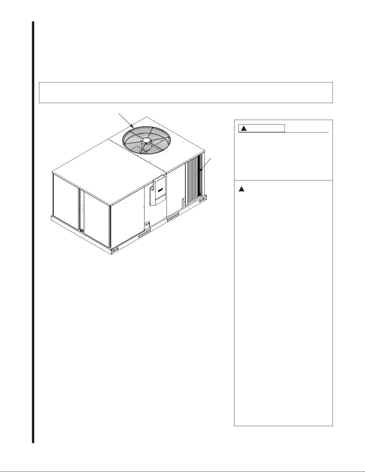
ONDENSER FAN
C
RILLE
G
!
WARNING
IF THE INFORMATION IN THESE
INSTRUCTIONS IS NOT FOLLOWED
EXHAUST OUTLET
COMBUSTION AIR
INLET HOOD
FURNACE CONTROL
ACCESS PANEL
BLOWER
ACCESS
PANEL
HOOD
CONDENSATE
DRAIN
FIELD THERMOSTAT
WIRING ENTRANCE
FIGURE 1. 3-6 TON COMMERCIAL MODELS
GAS SUPPLY
ENTRANCE
CONDENSER
AIR INLET
FIELD WIRING
ENTRANCE
MANUAL RESET
HIGH PRESSURE
CONTROL
(OPTIONAL)
EXACTLY, A FIRE OR EXPLOSION
MAY RESULT, CAUSING PROPERTY
DAMAGE, PERSONAL INJURY OR
DEATH.
!
FOR YOUR SAFETY
— Do not store or use gasoline or other
flammable vapors and liquids, or other
combustible materials in the vicinity of
this or any other appliance.
— WHAT TO DO IF YOU SMELL GAS
• Do not try to light any appliance.
• Do not touch any electrical switch;
do not use any phone in your
building.
• Immediately call your gas supplier
from a neighbor’s phone. Follow the
gas supplier’s instructions.
• If you cannot reach your gas supplier,
call the fire department.
• Do not return to your home until
authorized by the gas supplier or fire
department.
— DO NOT RELY ON SMELL ALONE TO
DETECT LEAKS. DUE TO VARIOUS
FACTORS, YOU MAY NOT BE ABLE
TO SMELL FUEL GASES.
• U.L. recognized fuel gas and CO
detectors are recommended in all
applications, and their installation
should be in accordance with the
manufacturer’s recommendations
and/or local laws, rules, regulations,
or customs
— Installation and service must be
performed by a qualified installer,
service agency or the gas supplier.
SUPERSEDES 92-20802-75-03
92-20802-75-04
Page 2
INTRODUCTION
Recognize this symbol as an indication of Important Safety Information!
!
This manual contains the operating
instructions for your combination
gas/electric year-round air
conditioner. There are precautions
that should be taken to maximize
atisfaction from this air conditioner.
s
IMPORTANT: COMPLETELY READ
ALL INSTRUCTIONS PRIOR TO
ATTEMPTING TO OPERATE OR
MAINTAIN THE PRODUCT.
his unit has been designed to give
T
you many years of efficient,
dependable comfort. With regular
maintenance, your unit will operate
satisfactorily year after year. Please
read this manual to familiarize
yourself with operation, maintenance
and safety procedures.
SAFETY
Carefully follow these safety rules:
1. The area around the unit must be
kept clear and free of all
combustible materials including
gasoline and other flammable
vapors and liquids.
2. Do not block the combustion air
inlets or the exhaust air outlet
openings. See Figures 1 and 2.
3. Do not operate the unit without
all panels and doors securely in
place.
!
WARNING
SHOULD OVERHEATING OCCUR
OR THE GAS SUPPLY FAIL TO
SHUT OFF, SHUT OFF THE
MANUAL GAS VALVE TO THE
APPLIANCE BEFORE SHUTTING
OFF THE ELECTRICAL SUPPLY.
FAILURE TO DO SO CAN RESULT
IN AN EXPLOSION OR FIRE
CAUSING PROPERTY DAMAGE,
SEVERE PERSONAL INJURY OR
DEATH!
4. Any additions, changes or
conversions required in order for
the unit to satisfactorily meet the
application needs should be
made by a qualified installer,
ervice agency or the gas
s
supplier, using factory specified
or approved parts. Read your
WARRANTY. Contact the
WARRANTOR for conversion
information. The unit was
equipped at the factory for use
on NATURAL GAS ONLY.
Conversion to LP GAS requires a
special kit supplied by the
WARRANTOR.
!
WARNING
OBSTRUCTION OF THE AIR VENT
ON AN LP TANK REGULATOR
CAN CAUSE EXPLOSION OR FIRE
RESULTING IN SERIOUS
PERSONAL INJURY, DEATH OR
PROPERTY DAMAGE.
PERIODICALLY INSPECT AND
CLEAN THE AIR VENT SCREEN
TO PREVENT ANY
OBSTRUCTION. KEEP
PROTECTIVE REGULATOR
COVER IN PLACE, AS EXPOSURE
TO THE ELEMENTS CAN CAUSE
ICE BUILDUP AND REGULATOR
FAILURE.
5. A gas burner needs an adequate
supply of combustion and
ventilation air for proper and safe
operation. Do not block or
obstruct air openings on the unit.
Do not place anything around the
unit that could block the flow of
fresh air to the unit.
6. Do not use this unit if any part
has been under water.
Immediately call a qualified
installer, service agency or the
gas supplier to inspect the unit
and to replace any part of the
control system or any gas control
that has been under water.
!
WARNING
O NOT ALLOW DEBRIS SUCH
D
AS LEAVES, GRASS, WEEDS,
SHRUBS, VINES OR SNOW
ACCUMULATE IN THE AREA
SURROUNDING THE UNIT,
PARTICULARLY IN THE VICINITY
OF THE VENT, AIR INTAKE AND
A/C CONDENSER FINS. DOING
SO CAN RESULT IN INADEQUATE
NIT PERFORMANCE OR CREATE
U
A FIRE HAZARD RESULTING IN
PROPERTY DAMAGE, PERSONAL
INJURY OR DEATH.
7. The combustion air inlet/exhaust
outlet hood and surrounding area
are very hot when operating in
heating mode. Do not allow
children to play on or around
the unit.
SYSTEM OPERATION
INFORMATION
Advice to the Customer
1. Keep the filter clean. Your system
will operate more efficiently and
provide better conditioned air.
2. Arrange your furniture and
drapes so that the supply and
return air registers and grilles are
unobstructed.
3. Close doors and windows. This
will reduce the cooling load on
your system for a more
economical operation.
4. Avoid excessive use of exhaust
fans.
5. Window shades and awnings will
reduce the cooling load.
6. Do not permit the heat generated
by television, lamps or radios to
influence the thermostat
operation.
7. Except for the mounting platform,
keep all combustible articles
2
Page 3

hree feet from the unit and
t
exhaust system.
8. Unless you plan to remove
panels to service the unit, do not
disconnect the main power to
your unit. This is a safety
precaution for the protection of
he compressor. Otherwise, use
t
the thermostat switches to shut
the system off.
9. For extended periods of
inoperation, set the thermostat
system switch in the “OFF”
position and fan switch in the
AUTO” position.
“
10. Do not allow the unit to become a
play stand for children.
THERMOSTAT OPERATION
We find most air conditioning units
are installed with a single stage
heating and cooling thermostat which
includes a manual heat/cool system
switch and a manual auto/on fan
switch.
For cooling, position the system
switch to
“Auto.” If constant fan operation is
desired, place the fan switch in the
“On” position.
When heating is desired, position the
system switch to “HEAT” and place the
fan switch in the “Auto” position.
During the heating season, the
operation of the warm air furnace is
automatic. Your installing dealer has
provided a wall mounted thermostat
which is sensitive to the change in the
temperature of the air moving around
the thermostat. When the temperature
of the air within the heated space
surrounding the thermostat decreases,
the thermostat switch functions to
initiate the ignition sequence and open
the gas valve.
“Cool” and the fan switch to
he spark ignitor located on the main
T
burner tray will safely ignite the gas
(natural or LP) leaving the main burner
ports. After approximately 30 seconds
of burner operation, the blower control
will start the blower. Warm air should
now gently circulate from the supply
diffusers throughout the dwelling and
return to the furnace through return air
rille(s).
g
When the temperature of the
circulating air reaches the temperature
setting of the thermostat, the gas valve
will reclose, the heat exchanger will
cool, and the blower will shut off after
90 seconds.
In the cooling mode, the compressor
and circulation air motor are energized
upon a call for cooling. When the
thermostat is satisfied or turned to the
“OFF” position, the compressor is deenergized, but the circulation air blower
continues to operate for approximately
60 seconds to extract the residual
cooling left in the cooling coil.
We suggest that you experiment with
constant air circulation during the
heating and cooling cycles. To achieve
this style of operation, place the fan
switch on the thermostat subbase to
the “on” position. You may enjoy the
comfort associated with the continuous
air movement, constant air filtration,
and the near even temperature from
floor to ceiling.
With continuous air circulation, some
condensation on the cooling coil can
reevaporate at the end of each cycle
and cause a buildup of humidity prior
to the next cooling cycle.
SELECTION OF ROOM
TEMPERATURE
It is most important to select the
omfort temperature you desire for
c
either heating or cooling by use of the
thermostat temperature selector.
DO NOT PLAY WITH THE
THERMOSTAT. SET IT AND FORGET
IT.
If the temperature selection procedure
is new to you, ask your installing
contractor to familiarize you with the
operation of the thermostat.
3
Page 4

HEATING OPERATION
ON
FOR YOUR SAFETY, READ
BEFORE OPERATING
!
WARNING
IF YOU DO NOT FOLLOW THESE
NSTRUCTIONS EXACTLY, A FIRE OR
I
EXPLOSION MAY RESULT CAUSING
PROPERTY DAMAGE, PERSONAL
INJURY OR LOSS OF LIFE.
A. This appliance is equipped with an
gnition device which automatically
i
lights the burners. Do not try to light the
burners by hand.
B. BEFORE OPERATING smell all
around the appliance area for gas. Be
sure to smell next to the ground
because some gas is heavier than air
and will settle on the ground.
WHAT TO DO IF YOU SMELL GAS
• Do not try to light any appliance.
• Do not touch any electric switch, do
not use any phone in your building.
• Immediately call your gas supplier
from a neighbor’s phone. Follow the
gas supplier’s
• If you cannot reach your gas
supplier, call the fire department.
• Do not return to your home until
authorized by the gas supplier for
fire department.
C. Use only your hand to push in or
turn the gas control knob. Never use
tools. If the knob will not push in or
turn by hand, don’t try to repair it,
call a qualified installer, service
agency or the gas supplier. Force or
attempted repair may result in a fire
or explosion.
D. Do not use this appliance if any part
has been under water. Immediately
call a qualified installer, service
agency or the gas supplier to
inspect the appliance and to replace
any part of the control system and
any gas control valve, electrical
components, motors or burners
which have been under water.
instructions.
4. Thirty seconds after the pressure
switch closes, the gas valve
opens and the ignitor sparks for
approximately 7 seconds or until
the remote flame is sensed at the
remote flame sensor. The induced
raft blower continues to run for the
d
complete heating cycle.
5. If the flame is not sensed during
this 7 second trial for ignition, the
control will repeat the prepurge
ycle and ignition cycle two (2)
c
additional times if needed.
6. After a total of three (3) cycles
without sensing main burner flame,
the system will then go into a 100%
lockout mode.
7. After one hour, the ignition control
will repeat the prepurge and
ignition cycles for 3 tries and then
go into 100% lockout mode again.
8. It will continue this sequence of
cycles and lockout each hour until
ignition is successful or power is
interrupted.
9. During the lockout mode, neither
the ignitor or the gas valve will be
energized until the system is reset
by turning the thermostat to the
“OFF” position or interrupting the
electrical power to the unit for 10
seconds or longer.
10. The induced draft blower and main
burner will shut off when the
thermostat is satisfied.
11. The fixed time blower control will
start the circulating air blower on
the heat speed approximately
twenty to thirty (20 to 30)
seconds after the main burners
are ignited.
Gas control
knob shown
in “OFF”
position.
12. The circulating air blower will
continue to run during the burner
operation and then shut down at
approximately ninety (90)
seconds after the thermostat
is satisfied and the burners
re shut off.
a
13. The circulating air blower will
start and run on the heat speed
if the thermostat fan switch is in
the “ON” position.
SUMMARY OF NORMAL
FURNACE OPERATING
SEQUENCE
1. Thermostat calls for heat
2. Induced draft blower is
energized.
3. Air proving pressure switch
closes.
4. 30 second prepurge is initiated.
5. Gas valve opens and ignitor is
energized for 7 second trial for
ignition period.
6. Burners ignite and flame sensor
proves all burners have lit
(maximum of 3 trials for ignition
each hour).
7. The circulating blower is
energized after 20-30 seconds.
8. Thermostat is satisfied and
opens.
9. The gas valve is de-energized
and closes, shutting down the
burner flame.
10. The circulating air blower is deenergized after 90 seconds.
Gas control
knob shown
in “OFF”
position.
SEQUENCE OF OPERATION
This unit is equipped with an integrated
circulating air blower/induced draft
blower control board that works in
conjunction with a remote sense direct
spark ignition control.
1. Each time thermostat contacts
close, the induced draft blower
operates a prepurge cycle.
2. The air proving negative pressure
switch closes.
3. The main gas burner cycle starts.
4
HONEYWELL VALVE
Gas control
knob shown
in “OFF”
position.
ROBERTSHAW 7200 VALVE
WHITE RODGERS VALVE
HONEYWELL VALVE
Page 5

LIGHTING INSTRUCTIONS
This appliance is equipped with a
direct spark intermittent ignition
device. This device lights the main
burners each time the room
hermostat (closes) calls for heat.
t
See lighting instruction on the
furnace.
TO START THE FURNACE
1. STOP! Read the safety
nformation on the Operating
i
Instructions Label located on this
appliance.
!
WARNING
IF YOU DO NOT FOLLOW THESE
INSTRUCTIONS EXACTLY, A FIRE
OR EXPLOSION MAY RESULT
CAUSING PROPERTY DAMAGE,
PERSONAL INJURY OR LOSS OF
LIFE.
2. Set the thermostat to the lowest
setting.
3. Turn off all electric power to the
appliance.
4. This appliance does not have a
pilot. It is equipped with an
ignition device which
automatically lights the burner.
Do NOT try to light the burner by
hand.
5. Remove control door/access
panel.
6. Move switch to the “OFF”
position.
7. Wait five (5) minutes to clear out
any gas. Then smell for gas,
including near the floor. If you
smell gas STOP!
• Do not try to light any
appliance.
• Do not touch any electric
switch; do not use any phone in
your building.
• Immediately call your gas
supplier from a neighbor’s
phone. Follow the gas
supplier’s instructions.
• If you cannot reach your gas
supplier, call the fire
department.
If you don’t smell gas, go to the
next step.
8. Move switch from “OFF” position
to “ON” position.
9. Replace control door.
10. Turn on all electric power to the
appliance.
1. Set the thermostat to desired
1
setting.
12. If the appliance will not operate,
follow the instructions “To Turn
Off Gas To Appliance” and call
your service technician or gas
supplier.
!
WARNING
THE SPARK IGNITOR AND
IGNITION LEAD FROM THE
GNITION CONTROL ARE HIGH
I
VOLTAGE. KEEP HANDS OR
TOOLS AWAY TO PREVENT
HAZARD FROM ELECTRICAL
SHOCK WHICH CAN RESULT IN
SEVERE PERSONAL INJURY OR
DEATH. SHUT OFF ELECTRICAL
POWER BEFORE SERVICING ANY
OF THE CONTROLS.
The initial start-up on a new
installation may require the control
system to be energized for some
time until any air has bled through
the system and fuel gas is available
at the burners.
TO SHUT DOWN FURNACE
1. Set the thermostat to the lowest
setting.
2. Turn off all electric power to the
appliance if service is to be
performed.
3. Remove control door.
4. Move switch to the “OFF”
position.
5. Replace control door.
!
WARNING
SHOULD OVERHEATING OCCUR
OR THE GAS SUPPLY FAIL TO
SHUT OFF, SHUT OFF THE
MANUAL GAS VALVE TO THE
APPLIANCE BEFORE SHUTTING
OFF THE ELECTRICAL SUPPLY.
FAILURE TO DO SO CAN CAUSE
AN EXPLOSION OR FIRE,
RESULTING IN PROPERTY
DAMAGE, SEVERE PERSONAL
INJURY OR DEATH.
MANUAL RESET
OVERTEMPERATURE
CONTROL
A manual reset limit control is located
on the burner shield. This device
senses blockage in the heat
exchanger or insufficient combustion
air. This will shut off the main burners
if excessive temperatures occur in
the burner compartment.
Operation of this control indicates an
abnormal condition. Therefore, the
unit should be examined by a
qualified installer, service agency, or
the gas supplier.
!
WARNING
DO NOT ATTEMPT TO DEFEAT
THIS IMPORTANT SAFETY
DEVICE. DO NOT RESET THE
OVERTEMPERATURE CONTROL
WITHOUT TAKING CORRECTIVE
ACTION TO ASSURE THAT AN
ADEQUATE SUPPLY OF
COMBUSTION AIR IS
MAINTAINED UNDER ALL
CONDITIONS OF OPERATION
AND THAT NO HEAT EXCHANGER
TUBES ARE BLOCKED OR
PERFORATED. REPLACE THIS
CONTROL ONLY WITH THE
IDENTICAL REPLACEMENT PART.
FAILURE TO ADHERE TO THIS
WARNING CAN RESULT IN
PERSONAL INJURY OR DEATH.
TROUBLESHOOTING HEATING
PROBLEM
Insufficient heating —
REMEDY
a. Increase temperature setting on
thermostat.
b. Check return air filters and
change, if necessary.
c. Recheck to assure that all supply
registers and diffusers are open.
d. Check closing of all doors and
windows.
e. Check that blower compartment
doors are in place.
f. Call your servicing contractor.
5
Page 6

COOLING OPERATION
To Operate Cooling System
o Start: Set thermostat at desired
T
setting with system switch on “Cool”
and fan switch on “Auto” or “On”
position.
To Shut Down: Set thermostat to
“Off” position.
SEQUENCE OF OPERATION
- COOLING
. Thermostat calls for cooling.
1
2. Compressor, condenser fan
motor, and circulation air blower
are energized.
3. Thermostat is satisfied and
opens.
4. Compressor and condenser fan
motor are de-energized.
5. Circulation air blower is deenergized after 60 seconds.
GENERAL INFORMATION COOLING
1. If your outdoor unit is equipped
with an optional external manual
high pressure switch reset
button, have your servicing
contractor familiarize you with its
location. Many models have
compressors equipped with
internal pressure relief valves
using an automatic reset feature
eliminating the need for an
external control. This high
pressure switch or the relief valve
will open under excessive high
pressures to protect the
compressor. Some models with
internal relief valves will require
power interruption prior to
resetting itself. The high
refrigerant pressure may be due
to a temporary condition, so if
your unit is equipped with a reset
button, you may reset it as
required. However, if the problem
persists, refer to Item 3, and/or
refer the problem to your
servicing contractor.
2. If the condenser coil is allowed to
become restricted by dirt, lint,
paper, grass clippings, leaves,
tc., the system efficiency will
e
suffer and abnormally high
refrigerant operating pressures
will result. To correct this
condition, be sure to first cut off
power to the unit and then clean
such material from the condenser
coil and cabinet. Using a garden
hose with a nozzle can be
ffective in cleaning the
e
condenser coil, but the water
should be sprayed from the
inside to outside of the coil in the
opposite direction from the
normal airflow. Disconnect the
main power before washing the
coil.
3. If you know or suspect that the
compressor s not working, you
should place the thermostat
system switch on the thermostat
subbase to the “Off” position.
This will stop the operation of the
compressor/condenser unit.
4. If you suspect that a cooling
problem has developed with your
system and before you advise
you servicing contractor, we
suggest you check the following
service hints.
TROUBLESHOOTING COOLING
PROBLEM
No cooling —
REMEDY
. Set thermostat correctly.
a
b. Reset high pressure switch on
unit.
c. Check fusing or circuit breakers
serving unit.
d. Call servicing contractor.
PROBLEM
Insufficient cooling —
Unit operates continuously
REMEDY
a. Check air filters.
b. Check for blocked return air
system.
c. Check to see if supply registers
have been closed.
d. Check for open doors and
windows.
e. Call your servicing contractor.
Please do not attempt any servicing
operation with which you are not
familiar or experienced unless you
are advised by your servicing
contractor of the proper procedures.
6
Page 7

ROUTINE MAINTENANCE
!
WARNING
ISCONNECT MAIN ELECTRICAL
D
POWER TO THE UNIT BEFORE
ATTEMPTING ANY
MAINTENANCE. FAILURE TO DO
SO CAN RESULT IN SEVERE
ELECTRICAL SHOCK OR DEATH.
Routine maintenance to be
rovided by a qualified installer,
p
service agency or the gas supplier
ONLY.
COMBUSTION AREA AND
EXHAUST SYSTEM
1. It is recommended that an annual
inspection of your furnace be
done by a qualified installer,
service agency or the gas
supplier.
2. Turn OFF the electrical supply to
the furnace and remove the
access doors.
3. Inspect the gas burners and
burner compartment for dirt, rust,
or scale.
!
WARNING
IF DIRT, RUST, SOOT OR SCALE
ACCUMULATIONS ARE PRESENT,
DO NOT OPERATE THIS
FURNACE. INSPECT THE HEAT
EXCHANGERS FOR LEAKS.
LEAKS CAN CAUSE TOXIC
FUMES TO ENTER THE HOME
AND CAUSE INJURY OR DEATH.
4. Inspect the exhaust area inside
and outside the appliance
including the exhaust transition
piece and the exhaust hood. Be
sure that the exhaust transition
piece (inside the appliance) and
the hood are in place and are
physically sound, without holes
or excessive corrosion. If these
components have deteriorated,
have a qualified service
professional replace them using
factory specified or approved
replacement parts only.
5. Be sure that the return air duct
connections are physically sound
and are sealed to the unit.
6. Look for obvious signs of
deterioration of the unit.
7. If the unit is free of the above
conditions, replace all access
doors, except furnace access
anel, and restore electrical
p
power to the unit.
8. Make sure control box cover is in
place. Start the furnace and
observe its operation. Watch the
burner flames to see if they are
bright blue. If a suspected
alfunction is observed, or the
m
burner flames are not bright blue,
apply appropriate service.
EXAMINATION OF
INSTALLATION
1. The combustion air inlets and
combustion air outlets must be
clear and free of obstructions.
2. The return and supply duct
connections should be physically
sound and sealed where they
connect to the unit.
3. Check for obvious signs of
deterioration of the unit.
4. CONDENSATE DRAIN — Check
annually and, if necessary, clean
drain pan and drain line. See
Figures 1 and 2 for location of
drain lines. In winter, keep drain
and trap dry or protect against
freeze-up.
5. The blower compartment and
motor should be inspected and
cleaned periodically by your
qualified installer, service agency
or the gas supplier to prevent the
possibility of overheating due to
an accumulation of dust and dirt
on the windings or on the motor
exterior. And, as suggested
elsewhere in these instructions,
the air filters should be kept
clean because dirty filters can
restrict airflow and the motor
depends upon sufficient air
flowing across and through it to
keep from overheating.
6. Perform the examination
annually to insure proper
operation.
FILTER MAINTENANCE
Have your qualified installer, service
agency or the gas supplier instruct
you on how to access your filters for
regular maintenance.
!
WARNING
DISCONNECT THE MAIN POWER
TO THE OUTDOOR UNIT BEFORE
TTEMPTING ANY MAINTENANCE
A
OPERATION. FAILURE TO DO SO
CAN RESULT IN SEVERE
ELECTRICAL SHOCK OR DEATH.
1. Keep air filters clean. There are
several types of material used in
air filters and there are many
possible locations for air filters.
Consult with your contractor as to
the locations of the filters and
type of material in use.
2. How To Clean:
Glass Fiber (Throwaway) —
This is a disposable type of filter.
Inspect monthly and replace
when necessary. A new home or
building will normally require
more frequent attention to the
filters.
Aluminum Mesh — Wash with
detergent and water. Air dry
thoroughly and renew the coating
in compliance with the
manufacturer’s instructions.
Plastic Impregnated Fiber —
Wash with detergent and water
or vacuum clean, then reinstall.
IMPORTANT: Do not operate
your system for extended
periods without filters, as the
dust entrained in the air may
pack into the fin area of the
evaporator coil creating a
condition which could require
extensive repairs.
7
Page 8

!
WARNING
A PORTION OF THE DUST
ENTRAINED IN THE AIR MAY
TEMPORARILY LODGE IN THE AIR
UCT RUNS AND AT THE SUPPLY
D
REGISTERS. ANY RECIRCULATED
DUST PARTICLES WILL BE HEATED
AND CHARRED BY CONTACT WITH
THE FURNACE HEAT EXCHANGER.
THIS RESIDUE WILL SOIL
CEILINGS, WALLS, DRAPES,
CARPETS, AND OTHER
HOUSEHOLD ARTICLES.
LUBRICATION
IMPORTANT: DO NOT attempt to
lubricate the bearings on the blower
motor or the induced draft blower
motor. Addition of lubricants can
reduce the motor life and void the
warranty.
The blower motor and induced draft
blower motor are prelubricated by the
manufacturer and do not require
further attention.
The blower motor and induced draft
blower motor must be cleaned
periodically by a qualified installer,
service agency, or the gas supplier to
prevent the possibility of overheating
due to an accumulation of dust and
dirt on the windings or on the motor
exterior. And, as suggested
elsewhere in these instructions, the
air filters can restrict airflow. The
motor depends upon sufficient air
flowing across and through it to keep
from overheating.
PROTECTING EQUIPMENT
FROM THE
ENVIRONMENT
The metal parts of this unit may be
subject to rust or deterioration in
adverse environmental conditions.
This oxidation could shorten the
equipment’s useful life. Salt spray,
fog or mist in seacoast areas,
sulphur or chlorine from lawn
watering systems, and various
hemical contaminants from
c
industries such as paper mills and
petroleum refineries are especially
corrosive.
!
WARNING
DISCONNECT ALL POWER TO
UNIT BEFORE STARTING
MAINTENANCE. FAILURE TO DO
SO CAN RESULT IN SEVERE
ELECTRICAL SHOCK OR DEATH.
1. Avoid having lawn sprinkler
heads spray directly on the unit
cabinet.
2. Frequent washing of the cabinet,
fan blade and coil with fresh
water will remove most of the salt
or other contaminants that build
up on the unit.
3. Regular cleaning and waxing of
the cabinet with a good
automobile polish will provide
some protection.
. A good liquid cleaner may be
4
used several times a year to
remove matter that will not wash
off with water.
Several different types of protective
coatings are offered in some areas.
These coatings may provide some
enefit, but the effectiveness of such
b
coating materials cannot be verified
by the equipment manufacturer.
The best protection is frequent
cleaning, maintenance and
inimal exposure to contaminants.
m
8 CM 0211
 Loading...