

Page 1

92-20521-32-04
SUPERSEDES 92-20521-32-03
▲WARNING
!
These instructions are intended as an aid to qualified licensed
service personnel for proper installation, adjustment and
operation of this unit. Read these instructions thoroughly before
attempting installation or operation. Failure to follow these
instructions may result in improper installation, adjustment,
service or maintenance possibly resulting in fire, electrical
shock, property damage, personal injury or death.
AIR HANDLERS
FEATURING R-22 REFRIGERANT:
(-)HLA High Efficiency
(-)HSA Standard Efficiency
FEATURING EARTH-FRIENDLY R-410A REFRIGERANT:
(-)HLL High Efficiency
(-)HSL Standard Efficiency
INSTALLATION INSTRUCTIONS
RECOGNIZE THIS SYMBOL AS AN INDICATION OF IMPORTANT SAFETY INFORMATION!
!
!
WARNING
THESE INSTRUCTIONS ARE INTENDED AS AN AID TO
QUALIFIED, LICENSED SERVICE PERSONNEL FOR PROPER
INSTALLATION, ADJUSTMENT AND OPERATION OF THIS UNIT.
READ THESE INSTRUCTIONS THOROUGHLY BEFORE
ATTEMPTING INSTALLATION OR OPERATION. FAILURE TO FOL-
LOW THESE INSTRUCTIONS MAY RESULT IN IMPROPER
INSTALLATION, ADJUSTMENT, SERVICE OR MAINTENANCE
POSSIBLY RESULTING IN FIRE, ELECTRICAL SHOCK,
PROPERTY DAMAGE, PERSONAL INJURY OR DEATH.
ISO 9001:2000
DO NOT DESTROY THIS MANUAL
PLEASE READ CAREFULLY AND KEEP IN A SAFE PLACE FOR FUTURE REFERENCE BY A SERVICEMAN
Page 2

2
TABLE OF CONTENTS
1.0 SAFETY INFORMATION . . . . . . . . . . . . . . . . . . . . . . . . . . . . . . . . . . . . . . . . . . . . 3
2.0 GENERAL INFORMATION . . . . . . . . . . . . . . . . . . . . . . . . . . . . . . . . . . . . . . . . . . 5
2.1 Important Information About Efficiency and Indoor Air Quality. . . . . . . . . . . . 5
2.2 Receiving . . . . . . . . . . . . . . . . . . . . . . . . . . . . . . . . . . . . . . . . . . . . . . . . . . . . 6
2.3 Clearances. . . . . . . . . . . . . . . . . . . . . . . . . . . . . . . . . . . . . . . . . . . . . . . . . . . 6
2.4 Model Number Explanation . . . . . . . . . . . . . . . . . . . . . . . . . . . . . . . . . . . . . . 7
2.4A Available Models . . . . . . . . . . . . . . . . . . . . . . . . . . . . . . . . . . . . . . . . . . 8
2.5 Dimensions and Weights . . . . . . . . . . . . . . . . . . . . . . . . . . . . . . . . . . . . . . . . 9
3.0 APPLICATIONS . . . . . . . . . . . . . . . . . . . . . . . . . . . . . . . . . . . . . . . . . . . . . . . . . . 10
3.1 Vertical Upflow. . . . . . . . . . . . . . . . . . . . . . . . . . . . . . . . . . . . . . . . . . . . . . . 10
3.2 Vertical Downflow. . . . . . . . . . . . . . . . . . . . . . . . . . . . . . . . . . . . . . . . . . . . . 10
3.3 Horizontal . . . . . . . . . . . . . . . . . . . . . . . . . . . . . . . . . . . . . . . . . . . . . . . . . . . 11
3.4 Installation in an Unconditioned Space . . . . . . . . . . . . . . . . . . . . . . . . . . . . 13
4.0 ELECTRICAL WIRING . . . . . . . . . . . . . . . . . . . . . . . . . . . . . . . . . . . . . . . . . . . . . 13
4.1 Power Wiring . . . . . . . . . . . . . . . . . . . . . . . . . . . . . . . . . . . . . . . . . . . . . . . . 13
4.2 Control Wiring . . . . . . . . . . . . . . . . . . . . . . . . . . . . . . . . . . . . . . . . . . . . . . . 14
4.3 Grounding . . . . . . . . . . . . . . . . . . . . . . . . . . . . . . . . . . . . . . . . . . . . . . . . . . 14
4.4 Copper Wire Size. . . . . . . . . . . . . . . . . . . . . . . . . . . . . . . . . . . . . . . . . . . . . 15
4.5 Blower Motor Electrical Data . . . . . . . . . . . . . . . . . . . . . . . . . . . . . . . . . . . . 15
4.5A Blower Motor Electrical Data: (-)HSA/(-)HSL. . . . . . . . . . . . . . . . . . . . 15
4.5B Blower Motor Electrical Data: (-)HLA/(-)HLL . . . . . . . . . . . . . . . . . . . . 15
4.6 Electric Heat Electrical Data . . . . . . . . . . . . . . . . . . . . . . . . . . . . . . . . . . . . 16
4.6A Electric Heat Electrical Data: (-)HSA/(-)HSL . . . . . . . . . . . . . . . . . . . . 16
4.6B Electric Heat Electrical Data: (-)HLA/(-)HLL . . . . . . . . . . . . . . . . . . . . 18
4.6C Heater Kit Supplemental Information . . . . . . . . . . . . . . . . . . . . . . . . . 20
5.0 AIRFLOW PERFORMANCE . . . . . . . . . . . . . . . . . . . . . . . . . . . . . . . . . . . . . . . . 21
5.1 Airflow Operatng Limits (-)HSA/(-)HSL . . . . . . . . . . . . . . . . . . . . . . . . . . . . 21
5.2 240V Airflow Performance Data (-)HSA/(-)HSL . . . . . . . . . . . . . . . . . . . . . . 22
5.3 115/208/480V Airflow Performance Data (-)HSA/(-)HSL . . . . . . . . . . . . . . . 24
5.4 115/208/240V Airflow Performance Data (-)HLA/(-)HLL . . . . . . . . . . . . . . . 26
6.0 DUCTWORK. . . . . . . . . . . . . . . . . . . . . . . . . . . . . . . . . . . . . . . . . . . . . . . . . . . . . 28
7.0 REFRIGERANT CONNECTIONS . . . . . . . . . . . . . . . . . . . . . . . . . . . . . . . . . . . . 28
7.1 TEV Sensing Bulb . . . . . . . . . . . . . . . . . . . . . . . . . . . . . . . . . . . . . . . . . . . . 28
7.2 Condensate Drain Tubing . . . . . . . . . . . . . . . . . . . . . . . . . . . . . . . . . . . . . . 28
7.3 Duct Flanges . . . . . . . . . . . . . . . . . . . . . . . . . . . . . . . . . . . . . . . . . . . . . . . . 29
8.0 AIR FILTER . . . . . . . . . . . . . . . . . . . . . . . . . . . . . . . . . . . . . . . . . . . . . . . . . . . . . 29
9.0 SEQUENCE OF OPERATION . . . . . . . . . . . . . . . . . . . . . . . . . . . . . . . . . . . . . . . 30
9.1 Cooling. . . . . . . . . . . . . . . . . . . . . . . . . . . . . . . . . . . . . . . . . . . . . . . . . . . . . 30
9.2 Heating (electric heat only) . . . . . . . . . . . . . . . . . . . . . . . . . . . . . . . . . . . . . 30
9.3 Heating (heat pump) . . . . . . . . . . . . . . . . . . . . . . . . . . . . . . . . . . . . . . . . . . 30
9.4 Blower Time Delay. . . . . . . . . . . . . . . . . . . . . . . . . . . . . . . . . . . . . . . . . . . . 30
9.5 Defrost Sequence . . . . . . . . . . . . . . . . . . . . . . . . . . . . . . . . . . . . . . . . . . . . 30
9.6 Emergency Heat . . . . . . . . . . . . . . . . . . . . . . . . . . . . . . . . . . . . . . . . . . . . . 31
9.7 Room Thermostat . . . . . . . . . . . . . . . . . . . . . . . . . . . . . . . . . . . . . . . . . . . . 31
10.0 CALCULATIONS . . . . . . . . . . . . . . . . . . . . . . . . . . . . . . . . . . . . . . . . . . . . . . . . . 31
10.1 Calculating Temperature Rise . . . . . . . . . . . . . . . . . . . . . . . . . . . . . . . . . . . 31
10.2 Calculating BTUH Heating Capacity . . . . . . . . . . . . . . . . . . . . . . . . . . . . . . 31
10.3 Calculating Airflow CFM. . . . . . . . . . . . . . . . . . . . . . . . . . . . . . . . . . . . . . . . 31
10.4 Calculating Correction Factor . . . . . . . . . . . . . . . . . . . . . . . . . . . . . . . . . . . 31
11.0 PRE-START CHECKLIST . . . . . . . . . . . . . . . . . . . . . . . . . . . . . . . . . . . . . . . . . . 32
12.0 MAINTENANCE . . . . . . . . . . . . . . . . . . . . . . . . . . . . . . . . . . . . . . . . . . . . . . . . . . 32
12.1 Air Filter . . . . . . . . . . . . . . . . . . . . . . . . . . . . . . . . . . . . . . . . . . . . . . . . . . . . 32
12.2 Indoor Coil/Drain Pan/Drain Line . . . . . . . . . . . . . . . . . . . . . . . . . . . . . . . . . 33
12.3 Blower Motor & Wheel . . . . . . . . . . . . . . . . . . . . . . . . . . . . . . . . . . . . . . . . . 33
12.4 Lubrication . . . . . . . . . . . . . . . . . . . . . . . . . . . . . . . . . . . . . . . . . . . . . . . . . . 33
12.5 Blower Assembly Removal & Replacement. . . . . . . . . . . . . . . . . . . . . . . . . 33
12.6 Motor Replacement . . . . . . . . . . . . . . . . . . . . . . . . . . . . . . . . . . . . . . . . . . . 34
12.7 Blower Wheel Replacement. . . . . . . . . . . . . . . . . . . . . . . . . . . . . . . . . . . . . 34
13.0 REPLACEMENT PARTS . . . . . . . . . . . . . . . . . . . . . . . . . . . . . . . . . . . . . . . . . . . 34
14.0 ACCESSORIES - KITS - PARTS . . . . . . . . . . . . . . . . . . . . . . . . . . . . . . . . . . . . . 35
Page 3

3
1.0 SAFETY INFORMATION
!
WARNING
Because of possible damage to
equipment or personal injury,
installation, service, and maintenance should be performed by a
trained, qualified service personnel. Consumer service is recommended only for filter cleaning/
replacement. Never operate the
unit with the access panels
removed.
!
WARNING (SEE WARNINGS IN REGARD TO DUCTWORK)
Do not install this unit in manufactured (mobile) homes. Improper installation is more likely in manufactured housing due to ductwork material, size,
location, and arrangement. Installations in manufactured housing can
cause a fire resulting in property damage, personal injury or death.
EXCEPTION
: Manufactured housing installations are approved only with
documentation by a recognized inspection authority that the installation
has been made in compliance with the instructions and all warnings have
been observed.
!
WARNING (SEE SECTION 3.2: VERTICAL DOWNFLOW)
The RXHB-17, RXHB-21 or RXHB-24 combustible floor base is required
when some units with electric heat are applied downflow on combustible
flooring. Failure to use the base can cause a fire resulting in property damage, personal injury or death. See CLEARANCES
for units requiring a combustible floor base. See the accessory section in this manual for combustible floor base RXHB.
!
WARNING
These instructions are intended as an aid to qualified, licensed service
personnel for proper installation, adjustment and operation of this unit.
Read these instructions thoroughly before attempting installation or operation. Failure to follow these instructions may result in improper installation, adjustment, service or maintenance possibly resulting in fire, electrical shock, property damage, personal injury or death.
!
WARNING
If removal of the blower assembly is
required, all disconnect switches
supplying power to the equipment
must be de-energized and locked (if
not in sight of unit) so the field
power wires can be safely removed
from the blower assembly. Failure to
do so can cause electrical shock
resulting in personal injury or
death.
!
WARNING
Disconnect all power to unit
before installing or servicing.
More than one disconnect switch
may be required to de-energize
the equipment. Hazardous voltage
can cause severe personal injury
or death.
(SEE SECTION 4.0:
ELECTRICAL WIRING)
(SEE SECTION 12.5: BLOWER
ASSEMBLY REMOVAL &
REPLACEMENT)
!
WARNING (SEE SECTION 4.3: GROUNDING)
The unit must be permanently grounded. Failure to do so can result in electrical shock causing personal injury or death.
Continued on next page ➜
!
WARNING
Duct leaks can create an unbalanced system and draw pollutants such as
dirt, dust, fumes and odors into the home causing property damage.
Fumes and odors from toxic, volatile or flammable chemicals, as well as
automobile exhaust and carbon monoxide (CO), can be drawn into the living space through leaking ducts and unbalanced duct systems causing
personal injury or death (see Figure 1).
• If air-moving equipment or ductwork is located in garages or off-garage
storage areas - all joints, seams, and openings in the equipment and
duct must be sealed to limit the migration of toxic fumes and odors
including carbon monoxide from migrating into the living space.
• If air-moving equipment or ductwork is located in spaces containing fuel
burning appliances such as water heaters or boilers - all joints, seams,
and openings in the equipment and duct must also be sealed to prevent
depressurization of the space and possible migration of combustion
byproducts including carbon monoxide into the living space.
!
WARNING (SEE SECTION 12.0: MAINTENANCE)
Units with circuit breaker(s) meet requirements as a service disconnect switch,
however, if access is required to the line side (covered) of the circuit breaker,
this side of the breaker(s) will be energized with the breaker(s) de-energized.
Contact with the line side can cause electrical shock resulting in personal
injury or death.
!
WARNING (SEE SECTION 5.0: DUCTWORK)
Do not, under any circumstances, connect return ductwork to any other
heat producing device such as fireplace insert, stove, etc. Unauthorized
use of such devices may result in fire, carbon monoxide poisoning, explosion, personal injury or property damage.
Page 4
4
!
CAUTION (SEE SECTION 3.3: HORIZONTAL)
Horizontal units must be configured for right hand air supply or left hand air
supply. Horizontal drain pan must be located under indoor coil. Failure to use
the drain pan can result in property damage.
!
WARNING (SEE SECTION 12.6: MOTOR REPLACEMENT)
To avoid electrical shock which can result in personal injury or death, use only
the screws furnished in the motor shell mounting holds. Screws are #8-18 x .25
in. long blunt nose thread forming. Screws longer than 1/4 in. may contact the
motor winding.
!
WARNING
PROPOSITION 65: This appliance
contains fiberglass insulation.
Respirable particles of fiberglass
are known to the State of California
to cause cancer.
All manufacturer products meet current Federal OSHA Guidelines for
safety. California Proposition 65
warnings are required for certain
products, which are not covered by
the OSHA standards.
California's Proposition 65 requires
warnings for products sold in
California that contain or produce
any of over 600 listed chemicals
known to the State of California to
cause cancer or birth defects such
as fiberglass insulation, lead in
brass, and combustion products
from natural gas.
All “new equipment” shipped for
sale in California will have labels
stating that the product contains
and/or produces Proposition 65
chemicals. Although we have not
changed our processes, having the
same label on all our products facilitates manufacturing and shipping.
We cannot always know “when, or
if” products will be sold in the
California market.
You may receive inquiries from customers about chemicals found in, or
produced by, some of our heating
and air-conditioning equipment, or
found in natural gas used with some
of our products. Listed below are
those chemicals and substances
commonly associated with similar
equipment in our industry and other
manufacturers.
• Glass Wool (Fiberglass) Insulation
• Carbon Monoxide (CO).
• Formaldehyde
• Benzene
More details are available at the
websites for OSHA (Occupational
Safety and Health Administration),
at www
.osha.gov and the State of
California’s OEHHA (Office of
Environmental Health Hazard
Assessment), at www
.oehha.org.
Consumer education is important
since the chemicals and substances
on the list are found in our daily
lives. Most consumers are aware
that products present safety and
health risks, when improperly used,
handled and maintained.
!
CAUTION (SEE SECTION 2.1: RECEIVING)
In compliance with recognized codes, it is recommended that an auxiliary
drain pan be installed under all evaporator coils or units containing evaporator coils that are located in any area of a structure where damage to the
building or building contents may occur as a result of an overflow of the
coil drain pan or a stoppage in the primary condensate drain piping. See
accessories for auxiliary horizontal overflow pan RXBM.
!
CAUTION
When used in cooling applications, excessive sweating may occur when
unit is installed in an unconditioned space. This can result in property
damage.
!
WARNING (SEE SECTION 7.0: AIR FILTER)
Do not operate the system without filters. A portion of the dust entrained in the
air may temporarily lodge in the duct runs and at the supply registers. Any circulated dust particles could be heated and charred by contact with the air handler elements. This residue could soil ceilings, walls, drapes, carpets and other
articles in the house.
Soot damage may occur with filters in place, when certain types of candles, oil
lamps or standing pilots are burned.
!
WARNING
The first 36 inches of supply air plenum and ductwork must be constructed of
sheet metal as required by NFPA 90B. The supply air plenum or duct must have
a solid sheet metal bottom directly under the unit with no openings, registers
or flexible air ducts located in it. If flexible supply air ducts are used they may
be located only in the vertical walls of a rectangular plenum, a minimum of 6
inches from the solid bottom. Metal plenum or duct may be connected to the
combustible floor base, if not, it must be connected to the unit supply duct
flanges such that combustible floor or other combustible material is not
exposed to the supply air opening from the downflow unit. Exposing combustible (non-metal) material to the supply opening of a downflow unit can
cause a fire resulting in property damage, personal injury or death.
Exceptions to do
wnflow warnings:
• Installations on concrete floor slab with supply air plenum and ductwork
completely encased in not less than 2 inches of concrete (See NFPA 90B).
!
NOTICE
Improper installation, or installation not made in accordance with the
Underwriters Laboratory (UL) certification or these instructions, can result
in unsatisfactory operation and/or dangerous conditions and are not covered by the unit warranty.
!
NOTICE
In compliance with recognized codes, it is recommended that an auxiliary
drain pan be installed under all evaporator coils or units containing evaporator coils that are located in any area of a structure where damage to the
building or building contents may occur as a result of an overflow of the
coil drain pan or a stoppage in the primary condensate drain piping. See
accessories section of these instructions for auxiliary horizontal overflow
pan information (model RXBM).
Page 5

5
2.0 GENERAL INFORMATION
2.1 IMPORTANT INFORMATION ABOUT EFFICIENCY AND INDOOR
2.1 AIR QUALITY
Central cooling and heating equipment is only as efficient as the duct system that carries the cooled or heated air. To maintain efficiency, comfort and good indoor air quality,
it is important to have the proper balance between the air being supplied to each room
and the air returning to the cooling and heating equipment.
Proper balance and sealing of the duct system improves the efficiency of the heating
and air conditioning system and improves the indoor air quality of the home by reducing
the amount of airborne pollutants that enter homes from spaces where the ductwork and
/ or equipment is located. The manufacturer and the U.S. Environmental Protection
Agency’s Energy Star Program recommend that central duct systems be checked by a
qualified contractor for proper balance and sealing.
FIGURE 1
MIGRATION OF DANGEROUS SUBSTANCES, FUMES, AND ODORS INTO LIVING SPACES
!
WARNING
!
NOTICE
Improper installation, or installa-tion not made in accordance with the
Underwriters Laboratory (UL) certification or these instructions, can result
in unsatisfactory operation and/or dangerous condi-tions and are not covered by the unit warranty.
Duct leaks can create an unbalanced system and draw pollutants such as
dirt, dust, fumes and odors into the home causing property damage.
Fumes and odors from toxic, volatile or flammable chemicals, as well as
automobile exhaust and carbon monoxide (CO), can be drawn into the living space through leaking ducts and unbalanced duct systems causing
personal injury or death (see Figure 1).
• If air-moving equipment or ductwork is located in garages or off-garage
storage areas - all joints, seams, and openings in the equipment and
duct must be sealed to limit the migration of toxic fumes and odors
including carbon monoxide from migrating into the living space.
• If air-moving equipment or ductwork is located in spaces containing fuel
burning appliances such as water heaters or boilers - all joints, seams,
and openings in the equipment and duct must also be sealed to prevent
depressurization of the space and possible migration of combustion
byproducts including carbon monoxide into the living space.
Page 6

6
2.2 RECEIVING
Immediately upon receipt, all cartons and contents should be inspected for transit damage. Units with damaged cartons should be opened immediately. If damage is found, it
should be noted on the delivery papers, and a damage claim filed with the last carrier.
• After unit has been delivered to job site, remove carton taking care not to damage
unit.
• Check the unit rating plate for unit size, electric heat, coil, voltage, phase, etc. to be
sure equipment matches what is required for the job specification.
• Read the entire instructions before starting the installation.
• Some building codes require extra cabinet insulation and gasketing when unit is
installed in attic applications.
• If installed in an unconditioned space, apply caulking around the power wires, control
wires, refrigerant tubing and condensate line where they enter the cabinet. Seal the
power wires on the inside where they exit conduit opening. Caulking is required to
pre-vent air leakage into and condensate from forming inside the unit, control box,
and on electrical controls.
• Install the unit in such a way as to allow necessary access to the coil/filter rack and
blower/control compartment.
• Install the unit in a level position to ensure proper condensate drainage. Make sure
unit is level in both directions within 1/8”.
• Install the unit in accordance with any local code which may apply and the national
codes. Latest editions are available from: “National Fire Protection Association, Inc.,
Batterysmarch Park, Quincy, MA 02269.” These publications are:
• ANSI/NFPA No. 70-(Latest Edition) National Electrical Code.
• NFPA90A Installation of Air Conditioning and Ventilating Systems.
• NFPA90B Installation of warm air heating and air conditioning systems.
• The equipment has been evaluated in accordance with the Code of Federal
Regulations, Chapter XX, Part 3280.
2.3 CLEARANCES
• All units are designed for “0” inches clearance to combustible material on all cabinet
surfaces.
• Some units require supply duct clearances and combustible floor bases depending on
the heating kW. The following table should be used to determine these requirements:
Units with electric heating kW above
that listed in the table require a one inch clear-
ance to combustible material for the first three feet of supply plenum and ductwork.
Additionally, if these units are installed downflow, a combustible floor base is
required.
Units with electric heating kW equal to
or less than the values listed in the table do
not require supply ductwork clearances or combustible floor bases.
• Vertical units require clearance on at least one side of the unit for electrical connec-
tions. Horizontal units require clearance on either top or bottom for electrical connections. Refrigerant and condensate drain connections are made on the front of the unit.
• All units require 24 inches minimum access to the front of the unit for service.
• These units may be installed in either ventilated or nonventilated spaces.
Model Cabinet Size 17 21 24
Model Designation kW 15 20 25
!
NOTICE
In compliance with recognized codes, it is recommended that an auxiliary
drain pan be installed under all evaporator coils or units containing evaporator coils that are located in any area of a structure where damage to the
building or building contents may occur as a result of an overflow of the
coil drain pan or a stoppage in the primary condensate drain piping. See
accessories section of these instructions for auxiliary horizontal overflow
pan information (model RXBM).
Page 7

7
FIGURE 2
MODEL NUMBER EXPLANATION
(-) H S A —HM18 17 J A
DESIGN VARIATION
A= 1STDESIGN
VOLTAGE
A = 115/1/60
D = 480V-3-60
J = 208/240/1/60
CAPACITY
18 = 18,000 BTU/H 42 = 42,000 BTU/H
24 = 24,000 BTU/H 48 = 48,000 BTU/H
30 = 30,000 BTU/H 60 = 60,000 BTU/H
36 = 36,000 BTU/H
HM = A/C OR HP MULTI-POSITION
HM = (Vertical Upflow/Horizontal Left is the factory configuration)
REFRIGERANT
A = R-22 L = R-410A
S = STANDARD MODEL (PSC MOTOR)
CABINET SIZE
17 = 17.5" (600 - 1200 CFM)
21 = 21" (1200 - 1600 CFM)
24 = 24.5" (1600 -1800 CFM)
TRADE BRAND
CLASSIFICATION
H = AIR HANDLER
2.4 MODEL NUMBER EXPLANATION
(-) H
L A —HM24 17 J A
DESIGN VARIATION
A= 1STDESIGN
VOLTAGE
A = 115/1/60
J = 208/240/1/60
CAPACITY
24 = 18,000 / 24,000 BTU/H
36 = 30,000 / 36,000 BTU/H
48 = 42,000 / 48,000 BTU/H
60 = 60,000 BTU/H
HM = A/C OR HP MULTI-POSITION
HM = (Vertical Upflow/Horizontal Left is the factory configuration)
REFRIGERANT
A = R-22 L = R-410A
L = HIGH EFFICIENCY (X-13 MOTOR)
CABINET SIZE
17 = 17.5" (600 - 1200 CFM)
21 = 21" (1400 - 1600 CFM)
24 = 24.5" (1600 - 1800 CFM)
TRADE BRAND
CLASSIFICATION
H = AIR HANDLER
Page 8

8
(-)HSA(L)-HM1817AA
(-)HSA(L)-HM2417AA
(-)HSA(L)-HM3017AA
(-)HSA(L)-HM3617AA
(-)HSA(L)-HM4221AA
(-)HSA(L)-HM4821AA
(-)HLA(L)-HM2417AA
(-)HLA(L)-HM3617AA
(-)HLA(L)-HM4821AA
(-)HLA(L)-HM4824AA
(-)HLA(L)-HM6024AA
AVAILABLE MODELS AT A VOLTAGE
AVAILABLE MODELS AT J VOLTAGE
AVAILABLE MODELS AT D VOLTAGE
Notes:
• Supply circuit protective devices may be fuses or “HACR” type circuit breakers.
• Largest motor load is included in single circuit and multiple circuit 1.
• If non-standard fuse size is specified, use next size larger fuse size.
• J Voltage (230V) single phase air handler is designed to be used with single or three
phase 230 volt power. In the case of connecting 3-phase power to the air handler terminal block, bring only two leads to the terminal block. Cap, insulate and fully secure
the third lead.
• (-)HSA-HM6024JA is ARI rated for three phase application only.
• The air handlers are shipped from the factory with the proper indoor coil installed, and
cannot be ordered without a coil.
• The air handlers do not have an internal filter rack. An external filter rack or other
means of filtration is required.
(-)HSA(L)-HM3617DA
(-)HSA(L)-HM3621DA
(-)HSA(L)-HM4221DA
(-)HSA(L)-HM4821DA
(-)HSA(L)-HM4824DA
(-)HSA(L)-HM6024DA
2.4A AVAILABLE MODELS
(-)HSA-HM1817JA
(-)HSA-HM2417JA
(-)HSA-HM3017JA
(-)HSA-HM3617JA
(-)HSA-HM3621JA
(-)HSA-HM4221JA
(-)HSA-HM4821JA
(-)HSA-HM4824JA
(-)HSA-HM6024JA
(-)HLA(L)-HM2417JA
(-)HLA(L)-HM3617JA
(-)HLA(L)-HM4821JA
(-)HLA(L)-HM4824JA
(-)HLA(L)-HM6024JA
Page 9

9
FIGURE 3
DIMENSIONS AND WEIGHTS
2.5 DIMENSIONS & WEIGHTS
A-1038-01
NOTE: 24" CLEARANCE REQUIRED
IN FRONT OF UNIT FOR FILTER
AND COIL MAINTENANCE.
ELECTRICAL CONNECTIONS
MAY EXIT TOP OR EITHER SIDE
HIGH VOLTAGE CONNECTION 7/8".
1 3/32", 1 31/32" DIA. KNOCK OUTS.
LOW VOLTAGE CONNECTION
5/8" AND 7/8" KNOCK OUT
(OUTSIDE OF CABINET)
FLANGES ARE PROVIDED
FOR FIELD INSTALLATION
AUXILIARY DRAIN CONNECTION
3/4" FEMALE PIPE THREAD (NPT)
HORIZONTALAPPLICATION ONLY
PRIMARY DRAIN CONNECTION
3/4" FEMALE PIPE THREAD (NPT)
AUXILIARY DRAIN CONNECTION
3/4" FEMALE PIPE THREAD (NPT)
UPFLOW/DOWNFLOW APPLICATION
ONLY
LIQUID LINE CONNECTION
COPPER (SWEAT)
VAPOR LINE CONNECTION
COPPER (SWEAT)
2111/16
105/16
SUPPLY AIR
W
A
H
191/2
RETURN AIR OPENING
UPFLOW UNIT SHOWN;
UNIT MAY BE INSTALLED UPFLOW, DOWNFLOW.
HORIZONTAL RIGHT, OR LEFT AIR SUPPLY.
DIMENSIONAL DATA
MODEL
SIZE
UNIT
WIDTH
“W” IN.
[mm]
SUPPLY
DUCT
“A” IN.
[mm]
AIRFLOW
COIL (NOM.) [L/s]
LO HI
UNIT WEIGHT / SHIPPING
WEIGHT (LBS.) [kg]
3017/3617
17
1
/2"
[444.5]
16"
[406.4]
1000
[472]
21"
[533.4]
19
1
/2"
[495.3]
1400
[661]
150/166
[68.0]/[75.2]
162/180
[73.4]/[81.6]
1600
[755]
1200
[566]
1600
[755]
—
23"
[581.2]
24
1
/2"
[622.3]
4221/4821
4824
181/198
[82.1]/[89.8]
—
1800
[850]
23"
[581.2]
24
1
/2"
[622.3]
UNIT
HEIGHT
IN. [mm]
421/2"
[1080]
50
1
/2"
[1283]
55
1
/2"
[1410]
551/2"
[1410]
6024
92/106
[41.7]/[48.0]
3621
21"
[533.4]
19
1
/2"
[495.3]
1200
[566]
—
421/2"
[1080]
97/112
[43.9]/[50.8]
1817/2417
17
1
/2"
[444.5]
16"
[406.4]
600
[283]
800
[378]
421/2"
[1080]
82/96
[37.1]/[43.5]
UNIT WITH
COIL (MAX. kW.)
Return Air Return Air Opening
Model
Opening Width Depth/Length
Cabinet Size
(Inches) (Inches)
17 157⁄8 193⁄4
21 193⁄8 193⁄4
24 227⁄8 193⁄4
Return Air Opening Dimensions
Page 10

10
3.0 APPLICATIONS
3.1 VERTICAL UPFLOW
• Vertical Upflow is the factory configuration for all models (see Figure 3).
• If a side return air opening is required, field fabricate a return air plenum with an opening large enough to supply unit and strong enough to support unit weight.
• If return air is to be ducted, install duct flush with floor. Use fireproof resilient gasket 1/8
to 1/4 in. thick between duct, unit and floor. Set unit on floor over opening
3.2 VERTICAL DOWNFLOW
Conversion to Vertical Downflow: A vertical upflow unit may be converted to vertical
downflow. Remove the door and indoor coil and reinstall 180° from original position (see
Figure 5).
IMPORTANT: To comply with certification agencies and the National Electric Code for
horizontal right application, the circuit breaker(s) on field-installed electric heater kits
must be re-installed per procedure below so that the breaker switch “on” position and
marking is up and, “off” position and marking is down.
- To turn breaker(s): Rotate one breaker pair (circuit) at a time starting with the one on the
right. Loosen both lugs on the load side of the breaker. Wires are bundles with wire ties,
one bundle going to the right lug and one bundle going to the left lug.
- Using a screwdriver or pencil, lift white plastic tab with hole away from breaker until
breaker releases from mounting opening (see Figure 5).
- With breaker held in hand, rotate breaker so that “on” position is up, “off” position is down
with unit in planned vertical mounting position. Insert right wire bundle into top right
breaker lug, ensuring all strands of all wires are inserted fully into lug, and no wire insulation is in lug.
- Tighten lug as tight as possible while holding circuit breaker. Check wires and make sure
each wire is secure and none are loose. Repeat for left wire bundle in left top circuit
breaker lug.
- Replace breaker by inserting breaker mounting tab opposite white pull tab in opening,
hook mounting tab over edge in opening.
FIGURE 4
DIMENSIONS FOR FRONT CONNECT COIL
515/16
41/8
31/16
13/16
11/8
11/16
13/8
213/16
51/4
53/8
Page 11

- With screwdriver or pencil, pull white tab with hole away from breaker while setting that
side of breaker into opening. When breaker is in place, release tab, locking circuit breaker into location in opening.
- Repeat above operation for remaining breaker(s) (if more than one is provided).
- Replace single point wiring jumper bar, if it is used, on line side of breaker and tighten
securely.
- Double check wires and lugs to make sure all are secure and tight. Check to make sure
unit wiring to circuit breaker load lugs match that shown on the unit wiring diagram.
• RXHB combustible floor base is used for all unit sizes. Unit must be centered on combustible base in the width dimension (14
3
/8”). (See Section 14.0 for more information
on the combustible floor base.)
3.3 HORIZONTAL
Horizontal left is the default factory configuration for “HM” (airflow direction) units.
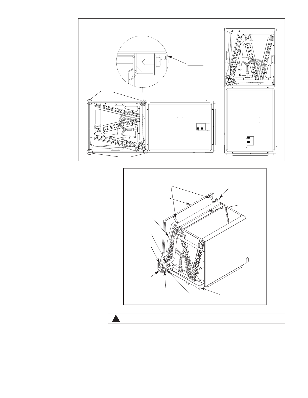
Conversion to Horizontal: A vertical upflow unit (AU) may be converted to horizontal by
removing the indoor coil and installing horizontal drain pan on coil as shown for right
hand or left hand air supply. Reinstall coil in unit as shown for right or left hand air supply. See Figures 6 & 7. (See Section 14.0 for more information on the Horizontal Adapter
Kit.)
• Rotate unit into the downflow position, with the coil compartment on top and the blower compartment on bottom.
• Reinstall the indoor coil 180° from original position. Ensure the retaining channel is fully
engaged with the coil rail. (See Figure 6, Detail A.)
• Secondary drain pan kits RXBM- are required when the unit is configured for the horizontal right position over a finished ceiling and/or living space. (See Section 14.0:
Accessories - Kits - Parts.)
IMPORTANT: Units cannot be installed horizontally laying on or suspended from the
back of the unit.
11
!
WARNING
The RXHB-17, RXHB-21 or RXHB-24 combustible floor base is required
when some units with electric heat are applied downflow on combustible
flooring. Failure to use the base can cause a fire resulting in property damage, personal injury or death. See CLEARANCES for units requiring a combustible floor base. See the accessory section in this manual for combustible floor base RXHB.
FIGURE 5
ROTATING CIRCUIT BREAKER
Page 12
12
!
CAUTION
Horizontal units must be configured for right hand air supply or left hand air
supply. Horizontal drain pan must be located under indoor coil. Failure to use
the drain pan can result in property damage.
FIGURE 6
VERTICAL DOWNFLOW & HORIZONTAL RIGHT APPLICATIONS
FIGURE 7
INDOOR COIL AND DRAIN PAN SET-UP
A-1037-01
HORIZONTALADAPTER
KIT
REAR WATER CATCHER
TOP AIR STOP
STRAPS
VAPOR LINE
CONNECTION
FRONT WATER
CATCHER
PRIMARY
DRAIN
CONNECTION
LIQUID LINE
CONNECTION
VERTICAL
DRAIN PAN
AUXILIARY
HORIZONTAL
DRAIN
CONNECTION
AUXILIARY
UPFLOW/DOWNFLOW
DRAIN CONNECTION
RAILS
RAILS
DETAIL A
ENSURE THE RETAIN-
ING CHANNEL IS FULLY
ENGAGED WITH THE
COIL RAIL.
Page 13
13
Conversion in Horizontal Direction: Horizontal left-hand supply can be changed to horizontal right-hand supply by removing the indoor coil and reinstalling 180° from original.
(See Figure 5.)
3.4 INSTALLATION IN AN UNCONDITIONED SPACE
IMPORTANT: There are two pairs of coil rails in the air handler for default and counter
flow application. If the air handler is installed in an unconditioned space, the two unused
coil rails should be removed to minimize air handler surface sweating. (See Figure 5.)
The coil rails can be easily removed by taking off the 6 mounting screws from both sides
of the cabinet.
4.0 ELECTRICAL WIRING
Field wiring must comply with the National Electric Code (C.E.C. in Canada) and any
applicable local ordinance.
4.1 POWER WIRING
It is important that proper electrical power is available for connection to the unit model
being installed. See the unit nameplate, wiring diagram and electrical data in the installation instructions.
• If required, install a branch circuit disconnect of adequate size, located within sight of,
and readily accessible to the unit.
• IMPORTANT: After the Electric Heater is installed, units may be equipped with one,
two, or three 30/60 amp. circuit breakers. These breaker(s) protect the internal wiring
in the event of a short circuit and serve as a disconnect. Circuit breakers installed
within the unit do not provide over-current protection of the supply wiring and therefore may be sized larger than the branch circuit protection.
• Supply circuit power wiring must be 75°C minimum copper conductors only. See
Electrical Data in this section for ampacity, wire size and circuit protector requirement.
Supply circuit protective devices may be either fuses or “HACR” type circuit breakers.
• Power wiring may be connected to either the right, left side or top. Three
7
/8”, 13/32”,
1
31
/32” dia. concentric knockouts are provided for connection of power wiring to unit.
• Power wiring is connected to the power terminal block in unit control compartment.
!
WARNING
Disconnect all power to unit before installing or servicing. More than one
disconnect switch may be required to de-energize the equipment.
Hazardous voltage can cause severe personal injury or death.
Page 14
14
4.2 CONTROL WIRING
IMPORTANT: Class 2 low voltage control wire should not be run in conduit with power
wiring and must be separated from power wiring, unless class 1 wire of proper voltage
rating is used.
• Low voltage control wiring should be 18 Awg. color-coded. For lengths longer than
100 ft., 16 Awg. wire should be used.
• Low voltage control connections are made to low voltage pigtails extending from top
of air handler (upflow position - see Figure 3). Connections for control wiring are
made with wire nuts. Control wiring knockouts (5/8 and 7/8) are also provided on the
right and left side of the unit for side connection.
• See wiring diagrams attached to indoor and outdoor sections to be connected, or control wiring diagram booklet supplied with outdoor heat pump section for wiring connection.
• Make sure, after installation, separation of control wiring and power wiring has been
maintained.
4.3 GROUNDING
• Grounding may be accomplished by grounding metal conduit when installed in accordance with electrical codes to the unit cabinet.
• Grounding may also be accomplished by attaching ground wire(s) to ground lug(s)
provided in the unit wiring compartment.
• Ground lug(s) are located close to wire entrance on left side of unit (upflow). Lug(s)
may be moved to marked locations near wire entrance on right side of unit (upflow), if
alternate location is more convenient.
• Use of multiple supply circuits require grounding of each circuit to lug(s) provided in
unit.
!
WARNING
The unit must be permanently grounded. Failure to do so can result in electrical shock causing personal injury or death.
Page 15
PHASE*
PHASE*
4.4 ELECTRICAL WIRING
POWER WIRING
• Field wiring must comply with the National Electrical Code (C.E.C. in Canada) and
any applicable local ordinance.
• Supply wiring must be 75°C minimum copper conductors only.
• See electrical data for product Ampacity rating and Circuit Protector requirement.
GROUNDING
• This product must be sufficiently grounded in accordance with National Electrical
Code (C.E.C. in Canada) and any applicable local ordinance.
• A grounding lug is provided.
15
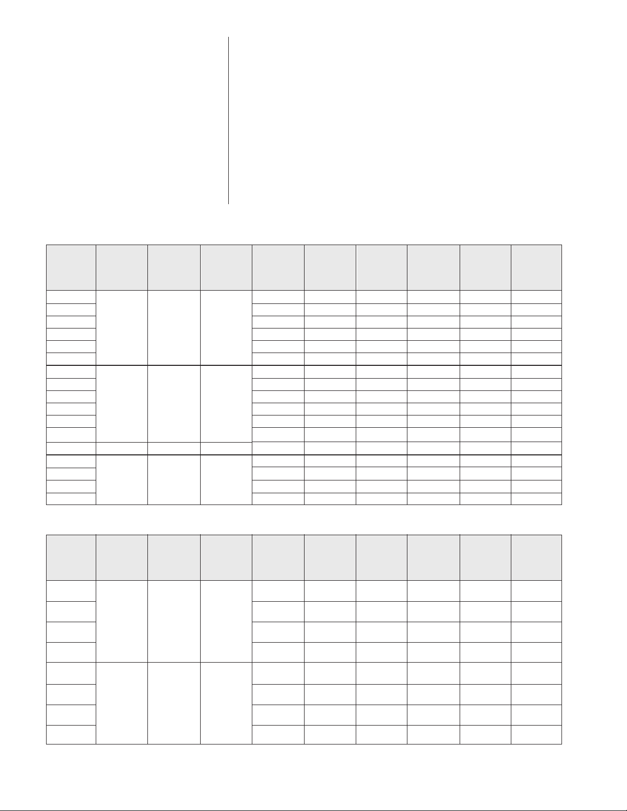
4.5A Electrical Data – Blower Motor Only – No Electric Heat: (-)HSA/(-)HSL
11/2 & 2 1/3 300-1100 4 1.6 2 15
21/2 & 3 1/2 300-1100 4 2.7 4 15
208/240 1 & 3 60
31/2 & 4 3/4 300-1100 4 3.8 5 15
5 3/4 300-1100 4 4.6 6 15
11/2 & 2 1/3 300-1100 4 4.8 6 15
21/2 & 3 1/2 300-1100 4 6.8 9 15
115 1 60
31/2 & 4 3/4 300-1100 4 8.4 11 15
5 3/4 300-1100 4 8.4 11 15
HP
NOMINAL
COOLING
CAPACITY
TONS
VOLTAGE HERTZ RPM SPEEDS
CIRCUIT
AMPS.
MINIMUM
CIRCUIT
AMPACITY
MAXIMUM
CIRCUIT
PROTECTOR
NOMINAL
COOLING
CAPACITY
TONS
VOLTAGE HERTZ HP RPM SPEEDS
CIRCUIT
AMPS.
MINIMUM
CIRCUIT
AMPACITY
MAXIMUM
CIRCUIT
PROTECTOR
4.5B Electrical Data – Blower Motor Only – No Electric Heat: (-)HLA/(-)HLL
11/2 1/5 1075 2 2.3 3.0 15
2 1/5 1075 2 3.8 5.0 15
21/2
115 1 60
1/4 1075 2 4.7 6.0 15
3 1/3 1075 2 6.1 8.0 15
31/2 1/2 1075 2 7.9 10.0 15
4 3/4 1075 2 8.4 11.0 15
11/2 1/5 1075 2 1.7 3.0 15
2 1/5 1075 2 1.7 3.0 15
21/2
208/240 1 & 3 60
1/4 1075 2 2.5 4.0 15
3 1/3 1075 2 2.5 4.0 15
31/2 1/2 1075 2 5.2 7.0 15
4 3/4 1075 2 5.2 7.0 15
5 208/240 3 60 3/4 1075 2 5.2 7.0 15
3 1/3 1075 2 1.4 2.0 15
31/2
480 3 60
1/3 1075 2 2.2 3.0 15
4 3/4 1075 2 2.2 3.0 15
5 3/4 1075 2 2.2 3.0 15
4.5 ELECTRICAL DATA – BLOWER MOTOR ONLY – NO ELECTRIC HEAT
*Blower motors are all single phase motors.
Page 16
16
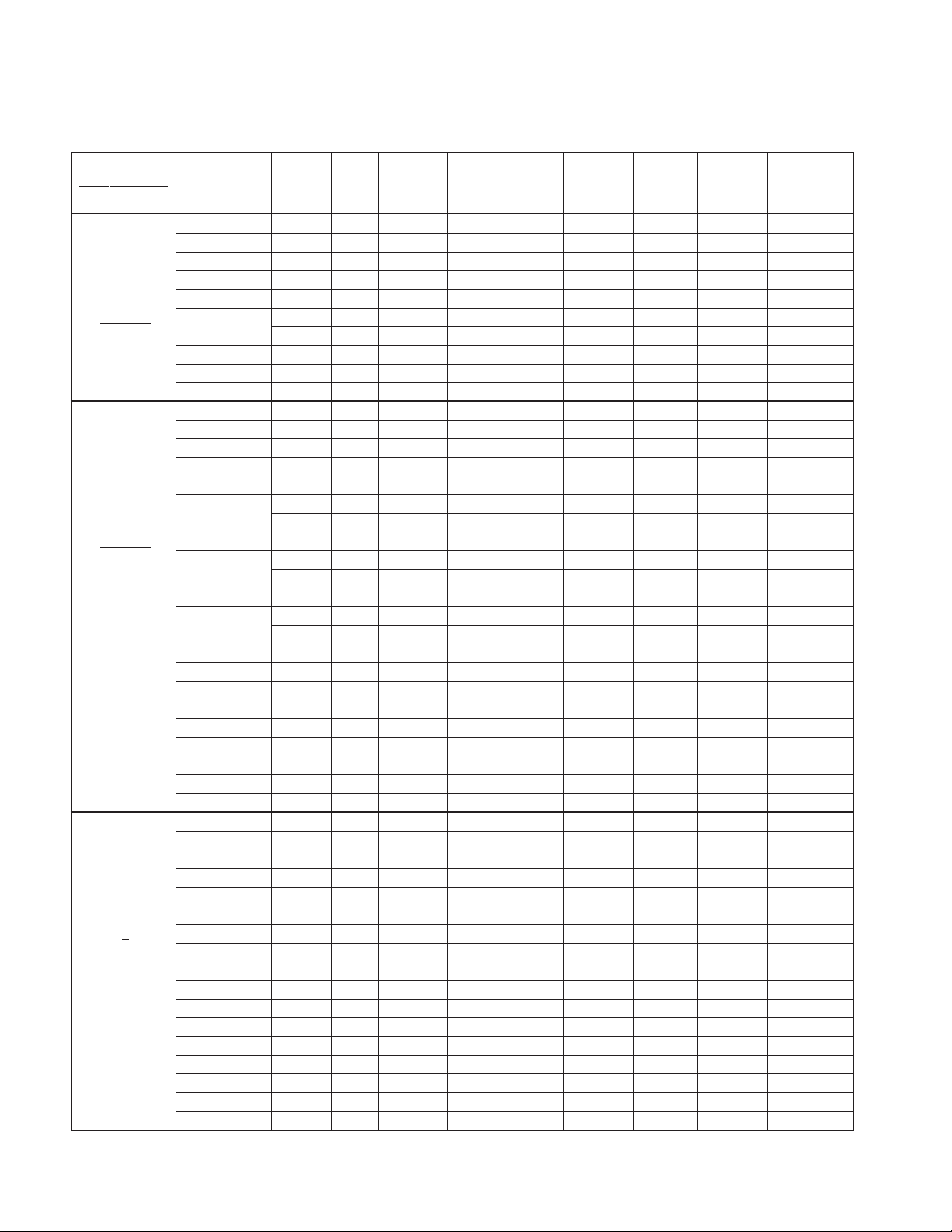
RXBH-17A03J 2.25/3.0 1/60 1-3.0 SINGLE 10.8/12.5 1.7 16/18 20/20
RXBH-17A05J 3.6/4.8 1/60 1-4.8 SINGLE 17.3/20.0 1.7 24/28 25/30
RXBH-17A07J 5.4/7.2 1/60 2-3.6 SINGLE 26.0/30.0 1.7 35/40 35/40
RXBH-17A10J 7.2/9.6 1/60 2-4.8 SINGLE 34.6/40.0 1.7 46/53 50/60
(-)HSA/(-)HSL RXBH-17A13J 9.4/12.5 1/60 3-4.17 SINGLE 45.1/52.1 1.7 59/68 60/70
1-1/2 & 2 3.1/4.2 1/60 1-4.17 MULTIPLE CKT 1 15.0/17.4 1.7 21/24 25/25
17
RXBH-17A13J
6.3/8.3 1/60 2-4.17 MULTIPLE CKT 2 30.1/34.7 0 38/44 40/45
RXBH-17A07C 5.4/7.2 3/60 3-2.4 SINGLE 15.0/17.3 1.7 21/24 25/25
RXBH-17A10C 7.2/9.6 3/60 3-3.2 SINGLE 20.0/23.1 1.7 28/31 30/35
RXBH-17A13C 9.4/12.5 3/60 3-4.17 SINGLE 26.1/30.1 1.7 35/40 35/40
RXBH-17A03J 2.25/3.0 1/60 1-3.0 SINGLE 10.8/12.5 2.5 17/19 20/20
RXBH-17A05J 3.6/4.8 1/60 1-4.8 SINGLE 17.3/20.0 2.5 25/29 25/30
RXBH-17A07J 5.4/7.2 1/60 2-3.6 SINGLE 26.0/30.0 2.5 36/41 40/45
RXBH-17A10J 7.2/9.6 1/60 2-4.8 SINGLE 34.6/40.0 2.5 47/54 50/60
RXBH-17A13J 9.4/12.5 1/60 3-4.17 SINGLE 45.1/52.1 2.5 60/69 60/70
3.1/4.2 1/60 1-4.17 MULTIPLE CKT 1 15.0/17.4 2.5 22/25 25/25
(-)HSA/(-)HSL
RXBH-17A13J
6.3/8.3 1/60 2-4.17 MULTIPLE CKT 2 30.1/34.7 0 38/44 40/45
2-1/2 & 3 RXBH-17A15J 10.8/14.4 1/60 3-4.8 SINGLE 51.9/60.0 2.5 68/79 70/80
17 3.6/4.8 1/60 1-4.8 MULTIPLE CKT 1 17.3/20.0 2.5 25/29 25/30
RXBH-17A15J
7.2/9.6 1/60 2-4.8 MULTIPLE CKT 2 34.6/40.0 0 44/50 45/50
RXBH-17A18J 12.8/17.0 1/60 3-5.68 SINGLE 61.6/70.8 2.5 81/92 90/100
4.3/5.7 1/60 1-5.68 MULTIPLE CKT 1 20.5/23.6 2.5 29/33 30/35
RXBH-17A18J
8.5/11.3 1/60 2-5.68 MULTIPLE CKT 2 41.1/47.2 0 52/59 60/60
RXBH-17A07C 5.4/7.2 3/60 3-2.4 SINGLE 15.0/17.3 2.5 22/25 25/25
RXBH-17A10C 7.2/9.6 3/60 3-3.2 SINGLE 20.0/23.1 2.5 29/32 30/35
RXBH-17A13C 9.4/12.5 3/60 3-4.17 SINGLE 26.1/30.1 2.5 36/41 40/45
RXBH-17A15C 10.8/14.4 3/60 3-4.8 SINGLE 30.0/34.6 2.5 41/47 45/50
RXBH-17A18C 12.8/17.0 3/60 3-5.68 SINGLE 35.5/41.0 2.5 48/55 50/60
RXBH-17A07D 7.2 3/60 2-3.6 SINGLE 8.7 1.4 13 15
RXBH-17A10D 9.6 3/60 3-3.2 SINGLE 11.6 1.4 17 20
RXBH-17A15D 14.4 3/60 3-4.8 SINGLE 17.3 1.4 24 25
RXBH-17A18D 17 3/60 3-5.68 SINGLE 20.4 1.4 28 30
RXBH-24A05J 3.6/4.8 1/60 1-4.8 SINGLE 17.3/20.0 2.5 25/29 25/30
RXBH-24A07J 5.4/7.2 1/60 2-3.6 SINGLE 26.0/30.0 2.5 36/41 40/45
RXBH-24A10J 7.2/9.6 1/60 2-4.8 SINGLE 34.6/40.0 2.5 47/54 50/60
RXBH-24A15J 10.8/14.4 1/60 3-4.8 SINGLE 51.9/60.0 2.5 68/79 70/80
3.6/4.8 1/60 1-4.8 MULTIPLE CKT 1 17.3/20.0 2.5 25/29 25/30
(-)HSA/(-)HSL
RXBH-24A15J
7.2/9.6 1/60 2-4.8 MULTIPLE CKT 2 34.6/40.0 0 44/50 45/50
3 RXBH-24A18J 12.8/17.0 1/60 4-4.26 SINGLE 61.6/70.8 2.5 81/92 90/100
21 6.4/8.5 1/60 2-4.26 MULTIPLE CKT 1 30.8/35.4 2.5 42/48 45/50
RXBJ-24A18J
6.4/8.5 1/60 2-4.26 MULTIPLE CKT 2 30.8/35.4 0 39/45 40/45
RXBH-24A07C 5.4/7.2 3/60 3-2.4 SINGLE 15.0/17.3 2.5 22/25 25/25
RXBH-24A10C 7.2/9.6 3/60 3-3.2 SINGLE 20.0/23.1 2.5 29/32 30/35
RXBH-24A15C 10.8/14.4 3/60 3-4.8 SINGLE 30.0/34.6 2.5 41/47 45/50
RXBH-24A18C 12.8/17.0 3/60 3-5.68 SINGLE 35.5/41.0 2.5 48/55 50/60
RXBH-24A07D 7.2 3/60 2-3.6 SINGLE 8.7 1.4 13 15
RXBH-24A10D 9.6 3/60 3-3.2 SINGLE 11.6 1.4 17 20
RXBH-24A15D 14.4 3/60 3-4.8 SINGLE 17.3 1.4 24 25
RXBH-24A18D 17 3/60 3-5.68 SINGLE 20.4 1.4 28 30
4.6 ELECTRICAL DATA – WITH ELECTRIC HEAT
4.6A ELECTRICAL DATA – WITH ELECTRIC HEAT: (-)HSA/(-)HSL
COOLING
CAPA
CITY TONS
CABINET SIZE
MODEL
NO.
HEATER
KW
208/240V
PH/HZ
NO.
ELEMENTS
- KW PER
TYPE SUPPLY
CIRCUIT
SINGLE CIRCUIT
MULTIPLE CIRCUIT
CIRCUIT
AMPS.
MOTOR
AMPACITY
MINIMUM
CIRCUIT
AMPACITY
MAXIMUM
CIRCUIT
PROTECTION
Installation of the UL Listed original equipment manufacturer provided heater kits listed in the following table is recommended for all
auxiliary heating requirements.
Page 17
17
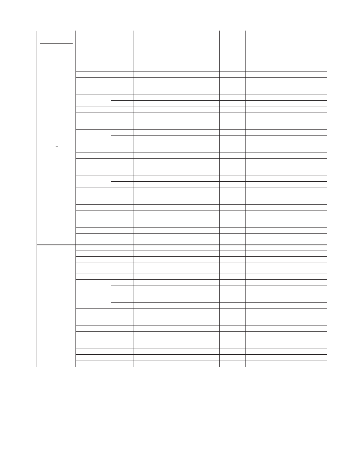
*Values only. No single point kit available.
NOTES:
• Electric heater BTUH - (heater watts + motor watts) x 3.414 (see airflow table for motor watts.)
• Supply circuit protective devices may be fuses or “HACR” type circuit breakers.
• If non-standard fuse size is specified, use next size larger standard fuse size.
• Largest motor load is included in single circuit or circuit 1 of multiple circuits.
• Heater loads are balanced on 3 phase models with 3 or 6 heaters only.
• No electrical heating elements are permitted to be used with A Voltage (115V) air handler.
• J Voltage (230V) signal phase air handler is designed to be used with single or three phase 230 volt electric heaters. In the case of connecting 3
phase power to air handler terminal block without the heater, bring only two leads to terminal block, cap, insulate and fully secure the third lead.
• Do not use 480 volts electrical heaters on 230 volts air handler.
• Do not use 230 volts electrical heaters on 480 volts air handler.
• If the kit is listed under both single and multiple circuits, the kit is shipped from factory as multiple circuits. For single phase application, Jumper
bar kit RXBJ-A21 and RXBJ-A31 can be used to convert multiple circuits to a single supply circuit. Refer to Accessory Section for details.
RXBH-24A05J 3.6/4.8 1/60 1-4.8 SINGLE 17.3/20.0 4.0 27/30 30/30
RXBH-24A07J 5.4/7.2 1/60 2-3.6 SINGLE 26.0/30.0 4.0 38/43 40/45
RXBH-24A10J 7.2/9.6 1/60 2-4.8 SINGLE 34.6/40.0 4.0 49/55 50/60
RXBH-24A15J 10.8/14.4 1/60 3-4.8 SINGLE 51.9/60.0 4.0 70/80 70/80
3.6/4.8 1/60 1-4.8 MULTIPLE CKT 1 17.3/20.0 4.0 27/30 30/30
RXBH-24A15J
7.2/9.6 1/60 2-4.8 MULTIPLE CKT 2 34.6/40.0 0.0 44/50 45/50
RXBH-24A18J 12.8/17 1/60 4-4.26 SINGLE 61.6/70.8 4.0 82/94 90/100
6.4/8.5 1/60 2-4.26 MULTIPLE CKT 1 30.8/35.4 4.0 44/50 45/50
RXBH-24A18J
6.4/8.5 1/60 2-4.26 MULTIPLE CKT 2 30.8/35.4 0.0 39/45 40/45
RXBH-24A20J 14.4/19.2 1/60 4-4.8 SINGLE 69.2/80 4.0 92/105 100/110
7.2/9.6 1/60 2-4.8 MULTIPLE CKT 1 34.6/40.0 4.0 49/55 50/60
(-)HSA/(-)HSL
RXBH-24A20J
7.2/9.6 1/60 2-4.8 MULTIPLE CKT 2 34.6/40.0 0.0 44/50 45/50
3-1/2 & 4 RXBH-24A25J 18.0/24.0 1/60 6-4.0 SINGLE 86.4/99.9 4.0 113/130 125/150
21 6.0/8.0 1/60 2-4.0 MULTIPLE CKT 1 28.8/33.3 4.0 42/47 45/50
and
RXBH-24A25J
6.0/8.0 1/6 2-4.0 MULTIPLE CKT 2 28.8/33.3 0.0 36/42 40/45
4
(4-ton only)
6.0/8.0 1/60 2-4.0 MULTIPLE CKT 3 28.8/33.3 0.0 36/42 40/45
24 RXBH-24A07C 5.4/7.2 3/60 3-2.4 SINGLE 15.0/17.3 4.0 24/27 25/30
RXBH-24A10C 7.2/9.6 3/60 3-3.2 SINGLE 20.0/23.1 4.0 30/34 30/35
RXBH-24A15C 10.8/14.4 3/60 3-4.8 SINGLE 30.0/34.6 4.0 43/49 45/50
RXBH-24A18C 12.8/17.0 3/60 3-2.84 SINGLE 35.6/41.0 4.0 50/57 50/60
RXBH-24A20C* 14.4/19.2 3/60 3-3.2 SINGLE 40.0/46.2 4.0 55/63 60/70
7.2/9.6 3/60 3-3.2 MULTIPLE CKT 1 20.0/23.1 4.0 30/34 30/35
RXBH-24A20C
7.2/9.6 3/60 3-3.2 MULTIPLE CKT 2 20.0/23.1 0.0 25/29 25/30
RXBH-24A25C* 18.0/24.0 3/60 6-4.0 SINGLE 50.0/57.8 4.0 68/78 70/80
RXBH-24A25C
9.0/12.0 3/60 3-4.0 MULTIPLE CKT 1 25.0/28.9 4.0 37/42 40/45
(4-ton only)
9.0/12.0 3/60 3-4.0 MULTIPLE CKT 2 25.0/28.9 0.0 32/37 35/40
RXBH-24A07D 7.2 3/60 2-3.6 SINGLE 8.7 2.2 14 15
RXBH-24A10D 9.6 3/60 3-3.2 SINGLE 11.6 2.2 18 20
RXBH-24A15D 14.4 3/60 3-4.8 SINGLE 17.3 2.2 25 25
RXBH-24A18D 17 3/60 3-5.68 SINGLE 20.4 2.2 29 30
RXBH-24A20D 19.2 3/60 6-3.2 SINGLE 23.2 2.2 32 35
RXBH-24A25D
(4-ton only)
24.0 3/60 6-4.0 SINGLE 28.8 2.2 39 40
RXBH-24A05J 3.6/4.8 1/60 1-4.8 SINGLE 17.3/20.0 4.4 28/31 30/35
RXBH-24A07C 5.4/7.2 3/60 3-2.4 SINGLE 15.0/17.3 4.4 25/28 25/30
RXBH-24A10C 7.2/9.6 3/60 3-3.2 SINGLE 20.0/23.1 4.4 31/35 35/35
RXBH-24A15C 10.8/14.4 3/60 3-4.8 SINGLE 30.0/34.6 4.4 43/49 45/50
RXBH-24A18C 12.8/17.0 3/60 3-2.84 SINGLE 35.6/41.0 4.4 50/57 50/60
RXBH-24A20C* 14.4/19.2 3/60 3-3.2 SINGLE 40.0/46.2 4.4 56/64 60/70
7.2/9.6 3/60 3-3.2 MULTIPLE CKT 1 20.0/23.1 4.4 31/35 35/35
RXBH-24A20C
7.2/9.6 3/60 3-3.2 MULTIPLE CKT 2 20.0/23.1 0 25/29 25/30
(-)HSA/(-)HSL RXBH-24A25C* 18.0/24.0 3/60 6-4.0 SINGLE 50.0/57.8 4.4 68/78 70/80
5 9.0/12.0 3/60 3-4.0 MULTIPLE CKT 1 25.0/28.9 4.4 37/42 40/45
24
RXBH-24A25C
9.0/12.0 3/60 3-4.0 MULTIPLE CKT 2 25.0/28.9 0 32/37 35/40
RXBH-24A30C* 21.6/28.8 3/60 6-4.8 SINGLE 60.0/69.4 4.4 81/93 90/100
10.8/14.4 3/60 3-4.8 MULTIPLE CKT 1 30.0/34.7 4.4 43/49 45/50
RXBH-24A30C
10.8/14.4 3/60 3-4.8 MULTIPLE CKT 2 30.0/34.7 0 38/44 40/45
RXBH-24A07D 7.2 3/60 2-3.6 SINGLE 8.7 2.2 14 15
RXBH-24A10D 9.6 3/60 3-3.2 SINGLE 11.6 2.2 18 20
RXBH-24A15D 14.4 3/60 3-4.8 SINGLE 17.3 2.2 25 25
RXBH-24A18D 17 3/60 3-5.68 SINGLE 20.4 2.2 29 30
RXBH-24A20D 19.2 3/60 6-3.2 SINGLE 23.2 2.2 32 35
RXBH-24A25D 24.0 3/60 6-4.0 SINGLE 28.8 2.2 39 40
RXBH-24A30D* 28.8 3/60 6-4.8 SINGLE 34.6 2.2 46 50
4.6A ELECTRICAL DATA – WITH ELECTRIC HEAT: (-)HSA/(-)HSL - continued
COOLING
CAP
ACITY TONS
CABINET SIZE
MODEL
NO.
HEATER
KW
208/240V
PH/HZ
NO.
ELEMENTS
- KW PER
TYPE SUPPLY
CIRCUIT
SINGLE CIRCUIT
MULTIPLE CIRCUIT
CIRCUIT
AMPS.
MOTOR
AMPACITY
MINIMUM
CIRCUIT
AMPACITY
MAXIMUM
CIRCUIT
PROTECTION
Page 18
18
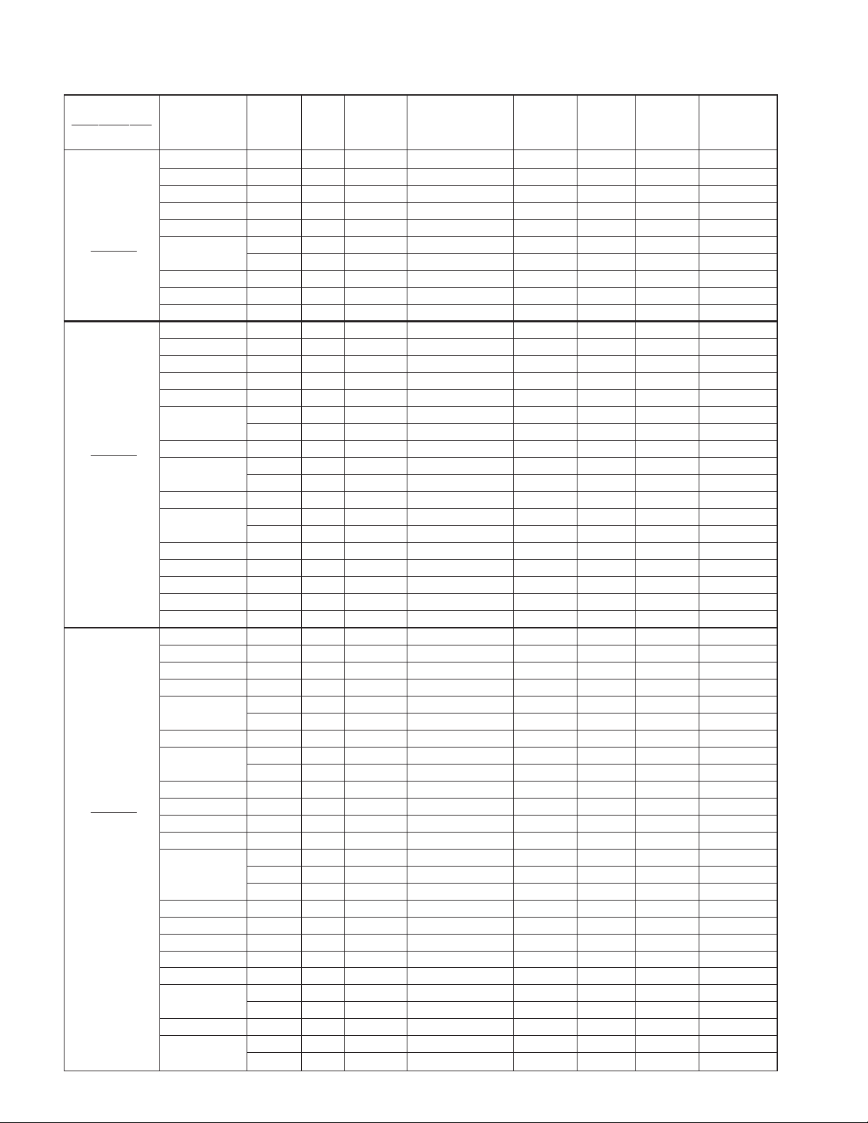
4.6B ELECTRICAL DATA – WITH ELECTRIC HEAT: (-)HLA/(-)HLL
RXBH-17A03J 2.25/3.0 1/60 1-3.0 SINGLE 10.8/12.5 1.6 16/18 20/20
RXBH-17A05J 3.6/4.8 1/60 1-4.8 SINGLE 17.3/20.0 1.6 24/27 25/30
RXBH-17A07J 5.4/7.2 1/60 2-3.6 SINGLE 26.0/30.0 1.6 35/40 35/40
RXBH-17A10J 7.2/9.6 1/60 2-4.8 SINGLE 34.6/40.0 1.6 46/52 50/60
(-)HLA/(-)HLL RXBH-17A13J 9.4/12.5 1/60 3-4.17 SINGLE 45.1/52.1 1.6 59/68 60/70
1-1/2 & 2 3.1/4.2 1/60 1-4.17 MULTIPLE CKT 1 15.0/17.4 1.6 21/24 25/25
17
RXBH-17A13J
6.3/8.3 1/60 2-4.17 MULTIPLE CKT 2 30.1/34.7 0 38/44 40/45
RXBH-17A07C 5.4/7.2 3/60 3-2.4 SINGLE 15.0/17.3 1.6 21/24 25/25
RXBH-17A10C 7.2/9.6 3/60 3-3.2 SINGLE 20.0/23.1 1.6 27/31 30/35
RXBH-17A13C 9.4/12.5 3/60 3-4.17 SINGLE 26.1/30.1 1.6 35/40 35/40
RXBH-17A03J 2.25/3.0 1/60 1-3.0 SINGLE 10.8/12.5 2.7 17/19 20/20
RXBH-17A05J 3.6/4.8 1/60 1-4.8 SINGLE 17.3/20.0 2.7 25/29 25/30
RXBH-17A07J 5.4/7.2 1/60 2-3.6 SINGLE 26.0/30.0 2.7 36/41 40/45
RXBH-17A10J 7.2/9.6 1/60 2-4.8 SINGLE 34.6/40.0 2.7 47/54 50/60
RXBH-17A13J 9.4/12.5 1/60 3-4.17 SINGLE 45.1/52.1 2.7 60/69 60/70
3.1/4.2 1/60 1-4.17 MULTIPLE CKT 1 15.0/17.4 2.7 23/26 25/30
(-)HLA/(-)HLL
RXBH-17A13J
6.3/8.3 1/60 2-4.17 MULTIPLE CKT 2 30.1/34.7 0 38/44 40/45
2-1/2 & 3
RXBH-17A15J 10.8/14.4 1/60 3-4.8 SINGLE 51.9/60.0 2.7 69/79 70/80
17 3.6/4.8 1/60 1-4.8 MULTIPLE CKT 1 17.3/20.0 2.7 25/29 25/30
RXBH-17A15J
7.2/9.6 1/60 2-4.8 MULTIPLE CKT 2 34.6/40.0 0 44/50 45/50
RXBH-17A18J 12.8/17.0 1/60 3-5.68 SINGLE 61.6/70.8 2.7 81/92 90/100
4.3/5.7 1/60 1-5.68 MULTIPLE CKT 1 20.5/23.6 2.7 29/33 30/35
RXBH-17A18J
8.5/11.3 1/60 2-5.68 MULTIPLE CKT 2 41.1/47.2 0 52/59 60/60
RXBH-17A07C 5.4/7.2 3/60 3-2.4 SINGLE 15.0/17.3 2.7 23/25 25/25
RXBH-17A10C 7.2/9.6 3/60 3-3.2 SINGLE 20.0/23.1 2.7 29/33 30/35
RXBH-17A13C 9.4/12.5 3/60 3-4.17 SINGLE 26.1/30.1 2.7 36/41 40/45
RXBH-17A15C 10.8/14.4 3/60 3-4.8 SINGLE 30.0/34.6 2.7 41/47 45/50
RXBH-17A18C 12.8/17.0 3/60 3-5.68 SINGLE 35.5/41.0 2.7 48/55 50/60
RXBH-24A05J 3.6/4.8 1/60 1-4.8 SINGLE 17.3/20.0 3.8 27/30 30/30
RXBH-24A07J 5.4/7.2 1/60 2-3.6 SINGLE 26.0/30.0 3.8 38/43 40/45
RXBH-24A10J 7.2/9.6 1/60 2-4.8 SINGLE 34.6/40.0 3.8 48/55 50/60
RXBH-24A15J 10.8/14.4 1/60 3-4.8 SINGLE 51.9/60.0 3.8 70/80 70/80
3.6/4.8 1/60 1-4.8 MULTIPLE CKT 1 17.3/20.0 3.8 27/30 30/30
RXBH-24A15J
7.2/9.6 1/60 2-4.8 MULTIPLE CKT 2 34.6/40.0 0.0 44/50 45/50
RXBH-24A18J 12.8/17.0 1/60 4-4.26 SINGLE 61.6/70.8 3.8 82/94 90/100
6.4/8.5 1/60 2-4.26 MULTIPLE CKT 1 30.8/35.4 3.8 44/49 45/50
RXBJ-24A18J
6.4/8.5 1/60 2-4.26 MULTIPLE CKT 2 30.8/35.4 0.0 39/45 40/45
(-)HLA/(-)HLL RXBH-24A20J 14.4/19.2 1/60 4-48 SINGLE 69.2/80 3.8 92/105 100/110
3-1/2 & 4
7.2/9.6 1/60 2-4.8 MULTIPLE CKT 1 34.6/40.0 3.8 48/55 50/60
21 RXBH-24A20J 7.2/9.6 1/60 2-4.8 MULTIPLE CKT 2 34.6/40.0 0.0 44/50 45/50
RXBH-24A25J 18.0/24.0 1/60 6-4.0 SINGLE 86.4/99.9 3.8 113/130 125/150
6.0/8.0 1/60 2-4.0 MULTIPLE CKT 1 28.8/33.3 3.8 41/47 45/50
RXBH-24A25J
6.0/8.0 1/60 2-4.0 MULTIPLE CKT 2 28.8/33.3 0.0 36/42 40/45
(4-ton only)
6.0/8.0 1/60 2-4.0 MULTIPLE CKT 3 28.8/33.3 0.0 36/42 40/45
RXBH-24A07C 5.4/7.2 3/60 3-2.4 SINGLE 15.0/17.3 3.8 24/27 25/30
RXBH-24A10C 7.2/9.6 3/60 3-3.2 SINGLE 20.0/23.1 3.8 30/34 30/35
RXBH-24A15C 10.8/14.4 3/60 3-4.8 SINGLE 30.0/34.6 3.8 43/48 45/50
RXBH-24A18C 12.8/17.0 3/60 3-2.84 SINGLE 35.6/41.0 3.8 50/56 50/60
RXBH-24A20C* 14.4/19.2 3/60 3-3.2 SINGLE 40.0/46.2 3.8 55/63 60/70
7.2/9.6 3/60 3-3.2 MULTIPLE CKT 1 20.0/23.1 3.8 30/34 30/35
RXBH-24A20C
7.2/9.6 3/60 3-3.2 MULTIPLE CKT 2 20.0/23.1 0.0 25/29 25/30
RXBH-24A25C* 18.0/24.0 3/60 6-4.0 SINGLE 50.0/57.8 3.8 68/77 70/80
RXBH-24A25C
9.0/12.0 3/60 3-4.0 MULTIPLE CKT 1 25.0/28.9 3.8 36/41 40/45
(4-ton only)
9.0/12.0 3/60 3-4.0 MULTIPLE CKT 2 25.0/28.9 0.0 32/37 35/40
COOLING
CAPACITY TONS
CABINET SIZE
MODEL
NO.
HEATER
KW
208/240V
PH/HZ
NO.
ELEMENTS
- KW PER
TYPE SUPPLY
CIRCUIT
SINGLE CIRCUIT
MULTIPLE CIRCUIT
CIRCUIT
AMPS.
MOTOR
AMPACITY
MINIMUM
CIRCUIT
AMPACITY
MAXIMUM
CIRCUIT
PROTECTION
Installation of the UL Listed original equipment manufacturer provided heater kits listed in the following table is recommended for all
auxiliary heating requirements.
Page 19
19
4.6B Electrical Data – With Electric Heat: (-)HLA/(-)HLL - continued
RXBH-24A07J 5.4/7.2 1/60 2-3.6 SINGLE 26.0/30.0 4.6 39/44 40/45
RXBH-24A10J 7.2/9.6 1/60 2-4.8 SINGLE 34.6/40.0 4.6 49/56 50/60
RXBH-24A15J 10.8/14.4 1/60 3-4.8 SINGLE 51.9/60.0 4.6 71/81 80/90
3.6/4.8 1/60 1-4.8 MULTIPLE CKT1 17.3/20.0 4.6 28/31 30/35
RXBH-24A15J
7.2/9.6 1/60 2-4.8 MULTIPLE CKT 2 34.6/40.0 0 44/50 45/50
RXBH-24A18J 12.8/17 1/60 4-4.26 SINGLE 61.6/70.8 4.6 83/95 90/100
6.4/8.5 1/60 2-4.26 MULTIPLE CKT 1 30.8/35.4 4.6 45/50 45/50
RXBH-24A18J
6.4/8.5 1/60 2-4.26 MULTIPLE CKT 2 30.8/35.4 0 39/45 40/45
RXBH-24A20J 14.4/19.2 1/60 4-4.8 SINGLE 69.2/80 4.6 93/106 100/110
7.2/9.6 1/60 2-4.8 MULTIPLE CKT 1 34.6/40.0 4.6 49/56 50/60
RXBH-24A20J
7.2/9.6 1/60 2-4.8 MULTIPLE CKT 2 34.6/40.0 0 44/50 45/50
RXBH-24A25J 18.0/24.0 1/60 6-4.0 SINGLE 86.4/99.9 4.6 114/131 125/150
6.0/8.0 1/60 2-4.0 MULTIPLE CKT 1 28.8/33.3 4.6 42/48 45/50
(-)HLA/(-)HLL RXBH-24A25J 6.0/8.0 1/60 2-4.0 MULTIPLE CKT 2 28.8/33.3 0 36/42 40/45
4 & 5 6.0/8.0 1/60 2-4.0 MULTIPLE CKT 3 28.8/33.3 0 36/42 40/45
24 RXBH-24A30J 21.6/28.8 1/60 6-4.8 SINGLE 103.8/120. 4.6 136/156 150/175
7.2/9.6 1/60 2-4.8 MULTIPLE CKT 1 34.6/40.0 4.6 49/56 50/60
RXBH-24A30J
7.2/9.6 1/60 2-4.8 MULTIPLE CKT 2 34.6/40.0 0 44/50 45/50
(5-ton only)
7.2/9.6 1/60 2-4.8 MULTIPLE CKT 3 34.6/40.0 0 44/50 45/50
RXBH-24A07C 5.4/7.2 3/60 3-2.4 SINGLE 15.0/17.3 4.6 25/28 25/30
RXBH-24A10C 7.2/9.6 3/60 3-3.2 SINGLE 20.0/23.1 4.6 31/35 35/35
RXBH-24A15C 10.8/14.4 3/60 3-4.8 SINGLE 30.0/34.6 4.6 44/49 45/50
RXBH-24A18C 12.8/17.0 3/60 3-2.84 SINGLE 35.6/41.0 4.6 51/57 60/60
RXBH-24A20C* 14.4/19.2 3/60 3-3.2 SINGLE 40.0/46.2 4.6 56/64 60/70
7.2/9.6 3/60 3-3.2 MULTIPLE CKT 1 20.0/23.1 4.6 31/35 35/35
RXBH-24A20C
7.2/9.6 3/60 3-3.2 MULTIPLE CKT 2 20.0/23.1 0 25/29 25/30
RXBH-24A25C* 18.0/24.0 3/60 6-4.0 SINGLE 50.0/57.8 4.6 69/78 70/80
9.0/12.0 3/60 3-4.0 MULTIPLE CKT 1 25.0/28.9 4.6 37/42 40/45
RXBH-24A25C
9.0/12.0 3/60 3-4.0 MULTIPLE CKT 2 25.0/28.9 0 32/37 35/40
RXBH-24A30C* 21.6/28.8 3/60 6-4.8 SINGLE 60.0/69.4 4.6 81/93 90/100
RXBH-24A30C
10.8/14.4 3/60 3-4.8 MULTIPLE CKT 1 30.0/34.7 4.6 44/50 45/50
(5-ton only)
10.8/14.4 3/60 3-4.8 MULTIPLE CKT 2 30.0/34.7 0 38/44 40/45
COOLING
CAP
ACITY T
ONS
CABINET SIZE
MODEL
NO.
HEATER
KW
208/240V
PH/HZ
NO.
ELEMENTS
- KW PER
TYPE SUPPLY
CIRCUIT
SINGLE CIRCUIT
MULTIPLE CIRCUIT
CIRCUIT
AMPS.
MOTOR
AMPACITY
MINIMUM
CIRCUIT
AMPACITY
MAXIMUM
CIRCUIT
PROTECTION
*Values only. No single point kit available.
NOTES:
• Electric heater BTUH - (heater watts + motor watts) x 3.414 (see airflow table for motor watts.)
• Supply circuit protective devices may be fuses or “HACR” type circuit breakers.
• If non-standard fuse size is specified, use next size larger standard fuse size.
• Largest motor load is included in single circuit or circuit 1 of multiple circuits.
• Heater loads are balanced on 3 phase models with 3 or 6 heaters only.
• No electrical heating elements are permitted to be used with A Voltage (115V) air handler.
• J Voltage (230V) signal phase air handler is designed to be used with single or three phase 230 volt electric heaters. In the case of connecting 3
phase power to air handler terminal block without the heater, bring only two leads to terminal block, cap, insulate and fully secure the third lead.
• Do not use 480 volts electrical heaters on 230 volts air handler.
• Do not use 230 volts electrical heaters on 480 volts air handler.
• If the kit is listed under both single and multiple circuits, the kit is shipped from factory as multiple circuits. For single phase application, Jumper
bar kit RXBJ-A21 and RXBJ-A31 can be used to convert multiple circuits to a single supply circuit. Refer to Accessory Section for details.
Page 20
20
4.6C HEATER KIT SUPPLEMENTAL INFORMATION
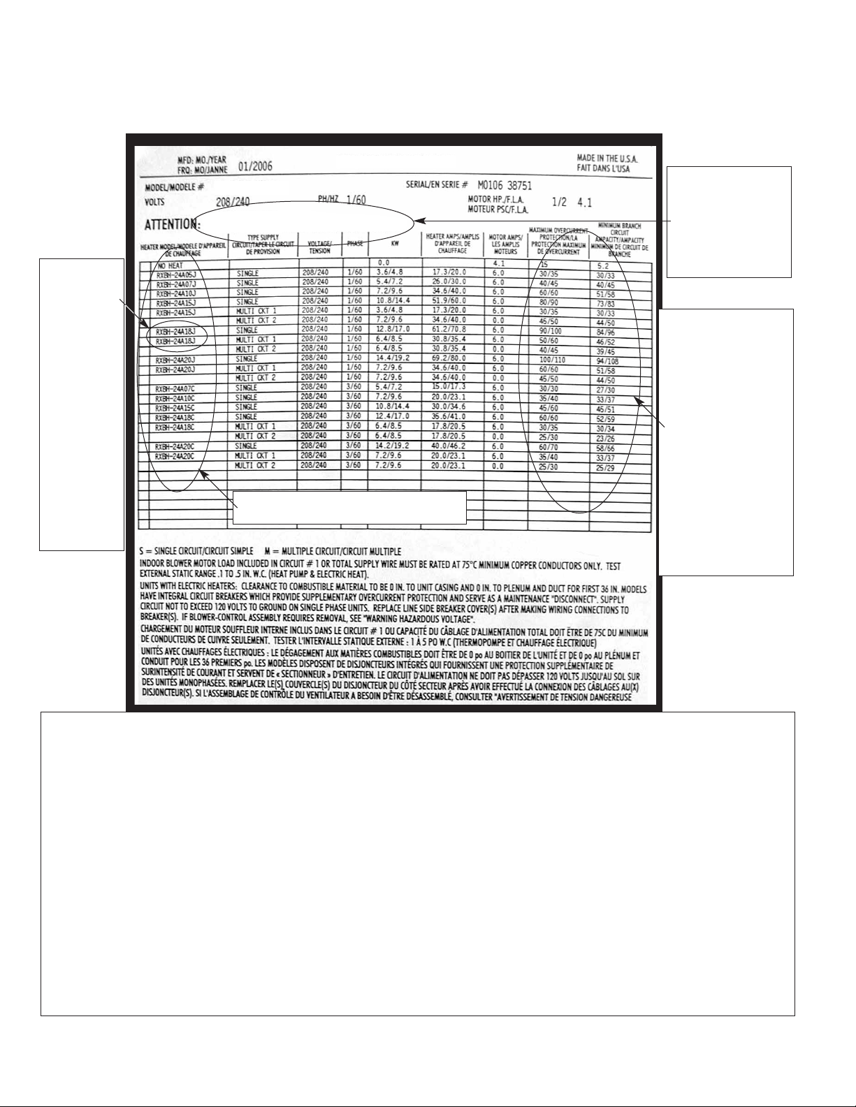
Heater Kit Supplemental Information: What allows the manufacturer to use standard Circuit Breakers
up to 60 amps inside the air handler, when using an approved Heater Kit?
National Electric Code (Section 424-22b) and our UL requirements allow us to subdivide heating element
circuits, of less than 48 amps, using breakers of not more than 60 amps and, additionally by, NEC 424-3b, a
rating not less than 125 percent of the load and NEC 424-22c, which describes the supplementary overcurrent protection required to be factory-installed within, or on the heater. The breakers in the heater kit are not,
and have never been, by NEC, intended to protect pwer wiring leading to the air handler unit. The breakers
in the heating kit are for short circuit proteciton. All internal unit wiring, where the breakers apply, has been
UL approved for short circuit protection.
Ampacity, (not breaker size), determines supply circuit wire size. The ampacity listed on the unit rating plate
and the Maximum and Minimum circuit breaker size (noted above) or in the units specification sheet or
installation instructions provides the information to properly select wire and circuit breaker/protector size. The
National Electric Code (NEC) specifies that the supply or branch circuit must be protected at the source.
These are the
required maximum and minimum circuit
breaker sizes
for overcurrent
protection and
should not be
confused with
the size of the
breakers
installed in the
heater kit.
Contractor
should “mark
or check” the
left column for
the kit installed
If a heater
kit is listed
both
Single
and Multicircuit, the
kit is
shipped
as a Multicircuit and
will
require a
single
point kit
Only listed kits can be applied
MARK HEATER INSTALLED/
L’APPAREIL DE CHAUFFAGE DE MARQUE A INSTALLE
(-)HLA-HM4821JA
AIR CONDITIONING DIVISION
Page 21
21
5.0 AIRFLOW PERFORMANCE
Airflow performance data is based on cooling performance with a coil and no filter in place.
Select performance table for appropriate unit size, voltage and number of electric heaters to
be used. Make sure external static applied to unit allows operation within the minimum and
maximum limits shown in table below for both cooling and electric heat operation. For optimum blower performance, operate the unit in the .3 to .7 in W.C. external static range. Units
with coils should be applied with a minimum of .1 in W.C. external static.
5.1 AIRFLOW OPERATING LIMITS
Cabinet Size 17 17 21 24
Cooling BTUH x 1,000 -018 -024 -030 -036 -042 -048 -048 -060
Cooling Tons Nominal 1.5 2 2.5 3 3.5 4 4 5
Heat Pump or Air Conditioning
Maximum Heat/Cool CFM [L/s] 675 900 1125 1350 1575 1800 1800 1930
(37.5 CFM [18 L/s]/1,000 BTUH) [319] [425] [531] [637] [743] [850] [850] [911]
(450 CFM [212 L/s]/Ton Nominal)
Heat Pump or Air Conditioning
Nominal Heat/Cool CFM [L/s] 600 800 1000 1200 1400 1600 1600 1800
(33.3 CFM [16 L/s]/1,000 BTUH) [283] [378] [472] [566] [661] [755] [755] [850]
(400 CFM [189 L/s]/Ton Nominal)
Heat Pump or Air Conditioning
Minimum Heat/Cool CFM [L/s] 540 720 900 1080 1260 1440 1440 1620
(30.0 CFM [14 L/s]/1,200 BTUH) [255] [340] [425] [510] [595] [680] [680] [765]
(360 CFM [170 L/s]/Ton Nominal)
Maximum kW Electric Heating 10 10 15 15 20 20 20 25
& Minimum Electric Heat CFM [L/s] 500 [236] 650 [308] 865 [408] 1015 [480] 1200 [566] 1400 [660] 1400 [660] 1730 [821]
Maximum Electric Heat Rise °F [°C] 85 [29] 85 [29] 85 [29] 85 [29] 85 [29] 85 [29] 85 [29] 85 [29]
Page 22
22
5.2 240V AIRFLOW PERFORMANCE DATA – (-)HSA/(-)HSL (PSC MOTOR)
Model
Number
Motor
Speed
From
Factory
Manufacturer
Recommended
Air Flow Range
(Min / Max) CFM
Blower Size/
Motor H.P.
# of Speeds
Motor
Speed
PSC
CFM[L/s] Air Delivery/RPM/Watts-240 Volts
External Static Pressure-Inches W.C.
0.10 [.02] 0.20 [.05] 0.30 [.07] 0.40 [.10] 0.50 [.12] 0.60 [.15] 0.70 [.17]
CFM
RPM
Watts
CFM
RPM
Watts
CFM
RPM
Watts
CFM
RPM
Watts
CFM
RPM
Watts
CFM
RPM
Watts
CFM
RPM
Watts
CFM
RPM
Watts
CFM
RPM
Watts
CFM
RPM
Watts
CFM
RPM
Watts
CFM
RPM
Watts
CFM
RPM
Watts
CFM
RPM
Watts
CFM
RPM
Watts
CFM
RPM
Watts
CFM
RPM
Watts
CFM
RPM
Watts
CFM
RPM
Watts
CFM
RPM
Watts
668 [315] 637 [301] 595 [281] 560 [264] 517 [244] — —
541 596 657 706 761 — —
180 171 166 161 155 — —
— — — — 711 [336] 662 [312] 614 [290]
— — — — 812 853 890
— — — — 243 227 210
638 [301] 607 [286] 565 [267] 530 [250] 487 [230] — —
571 626 687 736 791 — —
171 162 157 152 146 — —
— — — — 661 [312] 612 [289] 564 [266]
— — — — 837 878 915
— — — — 232 216 199
817 [386] 779 [368] 757 [357] 693 [327] 647 [305] — —
616 667 715 770 808 — —
239 230 221 206 196 — —
— — — — 888 [419] 828 [391] 774 [365]
— — — — 875 908 958
— — — — 331 313 301
787 [371] 749 [353] 727 [343] 663 [313] 617 [291] — —
646 697 745 800 838 — —
230 221 212 197 187 — —
— — — — 838 [395] 778 [367] 724 [342]
— — — — 900 933 983
— — — — 320 302 290
1022 [482] 987 [466] 940 [444] 903 [426] 864 [408] — —
700 754 794 833 870 — —
344 313 302 294 288 — —
— — — — 1004 [474] 951 [449] 883 [417]
— — — — 924 953 975
— — — — 364 352 344
972 [459] 937 [442] 890 [420] 853 [403] 814 [384] — —
750 804 844 883 920 — —
324 293 282 274 268 — —
— — — — 904 [427] 851 [402] 783 [370]
— — — — 949 978 1000
— — — — 334 322 314
1229 [580] 1201[567] 1170 [552] 1141 [538] 1104 [521] — —
788 833 872 909 951 — —
466 462 427 406 395 — —
— — — — 1248 [589] 1194 [563] 1133 [535]
— — — — 1008 1028 1042
— — — — 488 475 454
1179 [556] 1151 [543] 1120 [529] 1091 [515] 1054 [497] — —
838 883 922 959 1001 — —
446 442 407 386 375 — —
— — — — 1148 [542] 1094 [516] 1033 [487]
— — — — 1033 1053 1067
— — — — 458 445 424
1526 [720] 1474 [696] 1427 [673] 1307 [617] 1241 [586] — —
834 870 902 948 968 — —
560 549 535 476 462 — —
— — — — 1537 [725] 1418 [669] 1334 [630]
— — — — 1072 1077 1085
— — — — 860 835 820
1456 [687] 1404 [663] 1357 [640] 1237 [584] 1171 [553] — —
886 906 925 959 992 — —
542 524 505 468 431 — —
— — — — 1437 [678] 1318 [622] 1234 [582]
— — — — 1080 1090 1105
— — — — 840 800 785
1817
No heater
Low
240 V
517/711CFM
[244/336 L/s]
10x6
1/5 [149]
2 Speed
Low
High
1817
with 13kw
heater
Low
240 V
467/661 CFM
[230/312 L/s]
10x6
1/5 [149]
2 Speed
Low
High
2417
No heater
Low
240 V
647/888
[305.419 L/s]
10x6
1/5 [149]
2 Speed
Low
High
2417
with
13kw heater
Low
240 V
617/638
[291/395 L/s]
10x6
1/5 [149]
2 Speed
Low
High
3017
No heater
3017
with
18kw heater
Low
240 V
864/1004
[408/474 L/s]
10x8
1/4 [186]
2 Speed
Low
High
3617/3621
No heater
Low
240 V
814/904 CFM
[384/427 L/s]
10x8
1/4 [186]
2 Speed
Low
High
Low
240 V
1104/1248 CFM
[521/589 L/s]
10x8
1/3 [249]
2 Speed
Low
High
3617/3621
with
18kw heater
Low
240 V
1054/1148 CFM
[497/542 L/s]
10x8
1/3 [249]
2 Speed
Low
High
4221
No heater
Low
240 V
1241/1537 CFM
[586/725 L/s]
10x10
1/2 [373]
2 Speed
Low
High
4221
with
20kw heater
Low
240 V
1225/1500 CFM
[553/678 L/s]
10x10
1/2 [373]
2 Speed
Low
High
Page 23
23
NOTE:
• All 208/240V PSC motors have voltage taps for 208 and 240 volts.
• All 208/240V PSC motors are shipped on high speed and 240 volts.
• If the application external static is less than 0.5” WC, adjust the motor speed to the low static speed as described below.
- Unplug the black motor wire off the relay on the control board and plug in the red motor wire.
- Replace the cap on the black motor wire.
• Voltage change (208/240V motors):
- Move the orange lead to transformer 208V tap from 240V tap. Replace the wire cap on 240V tap.
- Unplug the purple motor wire off the transformer and plug in the yellow motor wire.
- Replace the cap on the purple motor wire.
• The above airflow table lists the airflow information for air handlers without heater and air handler with maximum heater allowed for each
model.
• The following formula can be used to calculate the approximate airflow, if a smaller (N kw) than the maximum heater kit is installed.
Approximate Airflow = Airflow without heater - (Airflow without heater - Airflow with maximum heater) X (N kw/maximum heater kw)
5.2 240V AIRFLOW PERFORMANCE DATA – (-)HSA/(-)HSL (PSC MOTOR) - continued
Model
Number
Motor
Speed
From
Factory
Manufacturer
Recommended
Air Flow Range
(Min / Max) CFM
Blower Size/
Motor H.P.
# of Speeds
Motor
Speed
PSC
CFM[L/s] Air Delivery/RPM/Watts-240 Volts
External Static Pressure-Inches W.C.
CFM
RPM
Watts
CFM
RPM
Watts
CFM
RPM
Watts
CFM
RPM
Watts
CFM
RPM
Watts
CFM
RPM
Watts
CFM
RPM
Watts
CFM
RPM
Watts
1741 [822] 1719 [811] 1667 [787] 1628 [768] 1572 [742] — —
878 920 950 981 1007 — —
785 757 707 667 641 — —
— — — — 1824 [861] 1767 [834] 1653 [780]
— — — — 1102 1112 1121
— — — — 871 830 770
1671 [789] 1649 [778] 1597 [754] 1558 [735] 1502 [709] — —
945 965 995 1025 1050 — —
715 685 650 630 610 — —
— — — — 1724 [814] 1667 [787] 1553 [733]
— — — — 1116 1119 1130
— — — — 810 780 730
1944 [917] 1912 [902] 1860 [878] 1813 [856] 1766 [833] — —
764 803 838 865 889 — —
779 763 747 729 708 — —
— — — — 1965 [927] 1908 [900] 1854 [875]
— — — — 943 967 977
— — — — 828 799 795
1844 [870] 1812 [855] 1760 [831] 1713 [808] 1666 [786] — —
839 865 890 913 935 — —
745 729 713 696 678 — —
— — — — 1865 [880] 1808 [853] 1754 [828]
— — — — 987 1001 1014
— — — — 788 766 744
4821/4824
No heater
Low
240 V
1572/1824 CFM
[742/861 L/s]
10x10
3/4 [559]
2 Speed
Low
High
4821/4824
with
25kw heater
Low
240 V
1225/1500
[709/814 L/s]
10x10
3/4 [559]
2 Speed
Low
High
6024
No heater
Low
240 V
1766/1965 CFM
[833/927 L/s]
11x11
3/4 [559]
2 Speed
Low
High
6024
with
30kw heater
Low
240 V
1225/1500
11x11
3/4 [559]
2 Speed
Low
High
0.10 [.02] 0.20 [.05] 0.30 [.07] 0.40 [.10] 0.50 [.12] 0.60 [.15] 0.70 [.17]
Page 24
24
5.3 115/208/480V AIRFLOW PERFORMANCE DATA – (-)HSA/(-)HSL (PSC MOTOR)
Model
Number
Motor
Speed
From
Factory
Manufacturer
Recommended
Air Flow Range
(Min / Max) CFM
Blower Size/
Motor H.P.
# of Speeds
Motor
Speed
PSC
CFM[L/s] Air Delivery/RPM/Watts-115/208/480 Volts
External Static Pressure-Inches W.C.
0.10 [.02] 0.20 [.05] 0.30 [.07] 0.40 [.10] 0.50 [.12] 0.60 [.15] 0.70 [.17]
CFM
RPM
Watts
CFM
RPM
Watts
CFM
RPM
Watts
CFM
RPM
Watts
CFM
RPM
Watts
CFM
RPM
Watts
CFM
RPM
Watts
CFM
RPM
Watts
CFM
RPM
Watts
CFM
RPM
Watts
CFM
RPM
Watts
CFM
RPM
Watts
CFM
RPM
Watts
CFM
RPM
Watts
CFM
RPM
Watts
CFM
RPM
Watts
CFM
RPM
Watts
CFM
RPM
Watts
CFM
RPM
Watts
CFM
RPM
Watts
681 [321] 636 [300] 606 [286] 567 [268] 523 [247] — —
541 601 670 714 768 — —
193 181 173 164 157 — —
— — — — 705 [333] 650 [307] 599 [283]
— — — — 815 861 989
— — — — 239 227 204
651 [307] 606 [286] 576 [272] 537 [253] 493 [233] — —
571 631 700 744 798 — —
184 172 164 155 148 — —
— — — — 655 [309] 600 [283] 549 [259]
— — — — 840 886 1014
— — — — 228 216 193
875 [413] 806 [380] 787 [371] 739 [349] 682 [322] — —
648 700 745 794 827 — —
259 255 243 234 227 — —
— — — — 897 [423] 851 [402] 765 [361]
— — — — 906 925 955
— — — — 332 318 306
845 [399] 776 [366] 757 [357] 709 [335] 652 [308] — —
678 730 775 824 857 — —
250 246 234 225 218 — —
— — — — 847 [400] 801 [378] 715 [337]
— — — — 931 950 980
— — — — 321 307 295
1038 [490] 1010 [477] 976 [461] 925 [437] 883 [417] — —
721 771 799 848 880 — —
325 314 303 290 286 — —
— — — — 1015 [479] 963 [454] 890 [420]
— — — — 928 955 974
— — — — 356 341 329
988 [466] 960 [453] 926 [437] 875 [413] 833 [393] — —
771 821 849 898 930 — —
305 294 283 270 266 — —
— — — — 915 [432] 863 [407] 790 [373]
— — — — 953 980 999
— — — — 326 311 299
1201 [567] 1170[552] 1141 [538] 1104 [521] 1062 [501] — —
833 872 909 951 965 — —
462 427 406 396 385 — —
— — — — 1194 [563] 1134 [535] 1078 [509]
— — — — 1024 1042 1060
— — — — 475 454 417
1151 [543] 1120 [529] 1091 [515] 1054 [497] 1012 [478] — —
883 922 959 1001 1015 — —
442 407 386 376 365 — —
— — — — 1094 [516] 1034 [488] 978 [462]
— — — — 1049 1067 1085
— — — — 445 424 387
1493 [705] 1449 [684] 1363 [643] 1287 [607] 1211 [571] — —
822 858 885 931 958 — —
540 519 506 484 459 — —
— — — — 1514 [714] 1411 [666] 1315 [621]
— — — — 1061 1069 1078
— — — — 710 702 677
1423 [672] 1379 [651] 1293 [610] 1217 [574] 1141 [538] — —
870 882 925 957 992 — —
514 508 490 461 431 — —
— — — — 1414 [667] 1311 [619] 1215 [573]
— — — — 1067 1080 1094
— — — — 700 678 665
1817
No heater
High
523/705CFM
[247/333 L/s]
10x6
1/5 [149]
2 Speed
Low
High
1817
with 13kw
heater
High
487/661 CFM
[230/312 L/s]
10x6
1/5 [149]
2 Speed
Low
High
2417
No heater
High
647/888
[305.419 L/s]
10x6
1/5 [149]
2 Speed
Low
High
2417
with
13kw heater
High
617/838
[291/395 L/s]
10x6
1/5 [149]
2 Speed
Low
High
3017
No heater
3017
with
18kw heater
High
864/1004
[408/474 L/s]
10x8
1/4 [186]
2 Speed
Low
High
3617/3621
No heater
High
814/904 CFM
[384/427 L/s]
10x8
1/4 [186]
2 Speed
Low
High
High
1104/1248 CFM
[521/589 L/s]
10x8
1/3 [249]
2 Speed
Low
High
3617/3621
with
18kw heater
High
1054/1148 CFM
[497/542 L/s]
10x8
1/3 [249]
2 Speed
Low
High
4221
No heater
High
1241/1537 CFM
[586/725 L/s]
10x10
1/2 [373]
2 Speed
Low
High
4221
with
20kw heater
High
1225/1500 CFM
[553/678 L/s]
10x10
1/2 [373]
2 Speed
Low
High
Page 25
25
5.3 115/208/480V AIRFLOW PERFORMANCE DATA – (-)HSA/(-)HSL (PSC MOTOR) - continued
NOTE:
• All 208/240V PSC motors have voltage taps for 208 and 240 volts.
• All 208/240V PSC motors are shipped on high speed and 240 volts.
• All 115V PSC motors are shipped on high speed.
• If the application external static is less than 0.5” WC, adjust the motor speed to the low static speed as described below:
- Unplug the black motor wire off the relay on the control board and plug in the red motor wire.
- Replace the cap on the black motor wire.
• Voltage change (208/240V motors):
- Move the orange lead to transformer to 208V tap from 240V tap. Replace the wire cap on 240V tap.
- Unplug the purple motor wire off the transformer and plug in the yellow motor wire.
- Replace the cap on the purple motor wire.
• All 480V PSC motors are shipped on high speed.
• If the application external static is less than 0.5” WC, adjust the motor speed to the low static speed as described below for 3-ton through
4-ton air handlers.
- Unplug the black motor wire off the relay and remove the cap from the red motor wire.
- Plug the red motor wire to the relay and connect the black motor wire with the yellow motor wire.
• For 5-ton air handler, unplug the black motor wire off the relay and plug in the red motor wire, then cap the black motor wire.
There is no yellow motor wire on 5-ton air handler.
WARNING: Do not connect red motor wire with yellow motor wire in any circumstance on 480V PSC motors. Connecting red motor wire with
yellow motor wire will result in permanent motor damage.
• The above airflow table lists the airflow information for air handlers without heater and air handler with maximum heater allowed for each
model.
• The following formula can be used to calculate the approximate airflow, if a smaller (N kw) than the maximum heater kit is installed.
Approximate Airflow = Airflow without heater - (Airflow without heater - Airflow with maximum heater) X (N kw/maximum heater kw)
Model
Number
Motor
Speed
From
Factory
Manufacturer
Recommended
Air Flow Range
(Min / Max) CFM
Blower Size/
Motor H.P.
# of Speeds
Motor
Speed
PSC
CFM[L/s] Air Delivery/RPM/Watts-115/208/480 Volts
External Static Pressure-Inches W.C.
CFM
RPM
Watts
CFM
RPM
Watts
CFM
RPM
Watts
CFM
RPM
Watts
CFM
RPM
Watts
CFM
RPM
Watts
CFM
RPM
Watts
CFM
RPM
Watts
1711 [807] 1689 [797] 1637 [773] 1598 [754] 1542 [728] — —
863 905 935 966 992 — —
765 737 687 647 621 — —
— — — — 1787 [843] 1679 [792] 1575 [743]
— — — — 1089 1098 1110
— — — — 695 665 630
1641 [774] 1619 [764] 1567 [739] 1528 [721] 1472 [695] — —
930 950 985 1015 1041 — —
700 660 630 600 580 — —
— — — — 1687 [796] 1579 [745] 1475 [696]
— — — — 1095 1107 1120
— — — — 670 635 615
1866 [881] 1833 [865] 1806 [852] 1772 [836] 1710 [807] — —
764 803 824 856 886 — —
778 756 733 715 701 — —
— — — — 1967 [928] 1916 [904] 1863 [879]
— — — — 948 959 991
— — — — 850 827 816
1796 [848] 1763 [832] 1736 [819] 1702 [803] 1640 [774] — —
828 860 878 890 1001 — —
735 718 705 695 678 — —
— — — — 1867 [881] 1816 [857] 1763 [832]
— — — — 989 1005 1020
— — — — 818 795 780
4821/4824
No heater
High
1572/1824 CFM
[742/861 L/s]
10x10
3/4 [559]
2 Speed
Low
High
4821/4824
with
25kw heater
High
1225/1500
[709/814 L/s]
10x10
3/4 [559]
2 Speed
Low
High
6024
No heater
High
1766/1965 CFM
[833/927 L/s]
11x11
3/4 [559]
2 Speed
Low
High
6024
with
30kw heater
High
1225/1500
[553/678 L/s]
11x11
3/4 [559]
2 Speed
Low
High
0.10 [.02] 0.20 [.05] 0.30 [.07] 0.40 [.10] 0.50 [.12] 0.60 [.15] 0.70 [.17]
Page 26
26
5.4 115/208/240V AIRFLOW PERFORMANCE DATA – (-)HLA/(-)HLL (X-13 MOTOR)
Model
Number
Motor
Speed
From
Factory
Tonnage
Application
Manufacturer
Recommended
Air Flow Range
(Min / Max) CFM
Blower Size/
Motor H.P.
# of Speeds
Motor
Speed
X-13
CFM[L/s] Air Delivery/RPM/Watts-115/208/240 Volts
External Static Pressure-Inches W.C.
0.10 [.02] 0.20 [.05] 0.30 [.07] 0.40 [.10] 0.50 [.12] 0.60 [.15] 0.70 [.17]
CFM
RPM
Watts
CFM
RPM
Watts
CFM
RPM
Watts
CFM
RPM
Watts
CFM
RPM
Watts
CFM
RPM
Watts
CFM
RPM
Watts
CFM
RPM
Watts
CFM
RPM
Watts
CFM
RPM
Watts
CFM
RPM
Watts
CFM
RPM
Watts
CFM
RPM
Watts
CFM
RPM
Watts
CFM
RPM
Watts
CFM
RPM
Watts
CFM
RPM
Watts
CFM
RPM
Watts
CFM
RPM
Watts
CFM
RPM
Watts
689 [325] 644 [304] 602 [284] 563 [266] 509 [240] — —
580 633 683 728 781 — —
66 84 86 88 91 — —
— — — — 681 [321] 644 [304] 603 [285]
— — — — 835 879 916
— — — — 136 143 152
670 [316] 625 [295] 583 [275] 544 [257] 490 [231] — —
608 661 711 756 809 — —
75 93 95 97 100 — —
— — — — 666 [314] 629 [297] 588[277]
— — — — 855 899 936
— — — — 144 151 160
875 [413] 839 [396] 804 [379] 762 [360] 730 [345] — —
679 724 765 810 852 — —
121 131 135 142 143 — —
— — — — 862 [407] 828 [391] 801 [378]
— — — — 904 940 970
— — — — 203 215 220
856 [404] 820 [387] 785 [370] 743 [351] 711 [336] — —
707 752 793 838 880 — —
130 140 144 151 152 — —
— — — — 837 [395] 803 [379] 776 [366]
— — — — 924 960 990
— — — — 211 223 228
1093 [516] 1050 [496] 1017 [480] 977 [461] 935 [441] — —
671 725 764 809 852 — —
153 168 174 180 188 — —
— — — — 1084 [512] 1040 [491] 1001 [472]
— — — — 896 936 971
— — — — 249 257 261
1068 [504] 1025 [484] 992 [468] 952 [449] 910 [429] — —
711 765 804 849 892 — —
164 179 185 191 199 — —
— — — — 1059 [500] 1015 [479] 976 [461]
— — — — 936 976 1011
— — — — 260 268 272
1270 [599] 1237 [584] 1199 [566] 1165 [550] 1130 [533] — —
775 816 846 882 926 — —
237 249 259 268 277 — —
— — — — 1275 [602] 1244 [587] 1211 [571]
— — — — 963 999 1029
— — — — 338 348 363
1245 [588] 1212 [572] 1174 [554] 1140 [538] 1105 [521] — —
815 856 886 922 966 — —
248 260 270 279 288 — —
— — — — 1250 [590] 1219 [575] 1186 [560]
— — — — 1003 1039 1069
— — — — 349 359 374
1473 [695] 1442 [681] 1401 [661] 1373 [648] 1337 [631] — —
781 825 867 905 949 — —
257 271 303 307 315 — —
— — — — 1447 [683] 1433 [676] 1402 [662]
— — — — 987 1034 1065
— — — — 394 406 405
1433 [676] 1402 [662] 1361 [642] 1333 [629] 1297 [612] — —
831 875 919 954 989 — —
277 295 313 319 325 — —
— — — — 1333 [629] 1300 [613] 1267 [598]
— — — — 1011 1046 1080
— — — — 350 364 377
2417
No heater
5
509/681CFM
[240/321 L/s]
10x6
1/3 [249]
5 Speed
2
3
2417
with
13kw heater
5
490/666 CFM
[231/314 L/s]
10x6
1/3 [249]
5 Speed
2
3
2417
No heater
5
730/651 CFM
[345/307 L/s]
10x6
1/3 [249]
5 Speed
4
5
2417
with
13kw heater
5
711/626 CFM
[336/295 L/s]
10x6
1/3 [249]
5 Speed
4
5
3617
No heater
3617
with
18kw heater
5
935/1084 CFM
[441/512 L/s]
10x8
1/2 [373]
5 Speed
2
3
3617
No heater
5
910/1059 CFM
[429/500 L/s]
10x8
1/2 [373]
5 Speed
2
3
5
1130/1275 CFM
[533/602 L/s]
10x8
1/2 [373]
5 Speed
4
5
3617
with
18kw heater
5
1105/1250 CFM
[521/590 L/s]
10x8
1/2 [373]
5 Speed
4
5
4821
No heater
5
1337/1447 CFM
[631/683 L/s]
10x10
3/4 [559]
5 Speed
2
3
4221
with
20kw heater
5
1.5
1.5
2.0
2.0
2.5
2.5
3.0
3.0
3.5
3.5
1297/1333 CFM
[612/629 L/s]
10x10
3/4 [559]
5 Speed
3
2
Page 27
27
5.4 115/208/240V AIRFLOW PERFORMANCE DATA – (-)HLA/(-)HLL (X-13 MOTOR) - continued
Model
Number
Motor
Speed
From
Factory
Tonnage
Application
Manufacturer
Recommended
Air Flow Range
(Min / Max) CFM
Blower Size/
Motor H.P.
# of Speeds
Motor
Speed
X-13
CFM[L/s] Air Delivery/RPM/Watts-115/208/240 Volts
External Static Pressure-Inches W.C.
0.10 [.02] 0.20 [.05] 0.30 [.07] 0.40 [.10] 0.50 [.12] 0.60 [.15] 0.70 [.17]
CFM
RPM
Watts
CFM
RPM
Watts
CFM
RPM
Watts
CFM
RPM
Watts
CFM
RPM
Watts
CFM
RPM
Watts
CFM
RPM
Watts
CFM
RPM
Watts
CFM
RPM
Watts
CFM
RPM
Watts
CFM
RPM
Watts
CFM
RPM
Watts
1665 [786] 1631 [770] 1601 [756] 1572 [742] 1535 [724] — —
853 893 934 968 1015 — —
351 387 401 406 422 — —
— — — — 1654 [781] 1624 [766] 1563 [738]
— — — — 1036 1078 1095
— — — — 500 513 523
1625 [767] 1591 [751] 1561 [737] 1532 [723] 1495 [706] — —
894 932 970 1020 1052 — —
389 400 410 430 450 — —
— — — — 1614 [762] 1584 [748] 1523 [719]
— — — — 1085 1090 1105
— — — — 514 520 530
1748 [825] 1669 [788] 1639 [773] 1599 [755] 1545 [729] — —
660 698 734 762 795 — —
297 311 326 340 353 — —
— — — — 1732 [817] 1683 [794] 1630 [769]
— — — — 840 872 899
— — — — 448 467 480
1708 [806] 1629 [769] 1599 [755] 1559 [736] 1505 [710] — —
680 736 760 790 820 — —
305 330 341 350 361 — —
— — — — 1692 [798] 1643 [775] 1590 [750]
— — — — 865 890 1014
— — — — 460 470 481
1902 [898] 1862 [879] 1809 [854] 1781 [840] 1739 [821] — —
712 749 787 815 856 — —
389 409 419 432 459 — —
— — — — 1905 [899] 1866 [881] 1832 [865]
— — — — 894 924 950
— — — — 565 570 592
1862 [879] 1822 [860] 1769 [835] 1741 [822] 1699 [802] — —
750 790 810 850 880 — —
410 420 430 455 479 — —
— — — — 1865 [880] 1826 [862] 1792 [846]
— — — — 920 945 970
— — — — 565 587 610
4821
No heater
5
1535/1654 CFM
[724/781 L/s]
10x10
3/4 [559]
5 Speed
4
5
4821
with
25kw heater
5
1495/1614 CFM
[706/762 L/s]
10x10
3/4[559]
5 Speed
4
5
4824
No heater
3
1545/1732 CFM
[729/817 L/s]
11x11
3/4 [559]
5 Speed
2
3
4824
with
25kw heater
3
1505/1692 CFM
[710/798 L/s]
11x11
3/4 [559]
5 Speed
2
3
6024
No heater
6024
with
33kw heater
5
1739/1905 CFM
[821/899 L/s]
11x11
3/4 [559]
5 Speed
4
5
5
1699/1865 CFM
[802/880 L/s]
11x11
3/4 [559]
5 Speed
4
5
4.0
4.0
4.0
4.0
5.0
5.0
NOTE:
X-13 motor speed changes
All X-13 motors have 5 speed tabs. Speed tab 1 is for continuous fan. Speed tab 2 (low static) and Speed tab 3 (high static) are for lower tonnage. Speed tab 4 (low static) and Speed tab 5 (high static) are for higher tonnage.
X-13 air handlers are always shipped from factory at speed tab 5, except for -4824, which is set at speed tab 3. For instance, RHLA-HM2417JA is always shipped at high
static 2-ton airflow (Speed tab 5). To change to 1.5-ton airflow, move the blue wire to Speed tab 2 or 3 on the X-13 motor.
The low static Speed tab 2 (lower tonnage) and 4 (higher tonnage) are used for external static below 0.5” WC. The high static Speed tab 3 (lower tonnage) and 5 (higher
tonnage) are used for external static exceeding 0.5” WC. Move the blue wire to the appropriate speed tab as required by the application needs.
• The airflow for continuous fan (Speed tab 1) is always set at 50% of the Speed tab 4.
• The above airflow table lists the airflow information for air handlers without heater and air handler with maximum heater allowed for each model.
• The following formula can be used to calculate the approximate airflow, if a smaller (N kw) than the maximum heater kit is installed.
Approximate Airflow = Airflow without heater - (Airflow without heater - Airflow with maximum heater) X (N kw/maximum heater kw)
Page 28

28
6.0 DUCTWORK
Field ductwork must comply with the National Fire Protection Association NFPA 90A,
NFPA 90B and any applicable local ordinance.
Sheet metal ductwork run in unconditioned spaces must be insulated and covered with a
vapor barrier. Fibrous ductwork may be used if constructed and installed in accordance
with SMACNA Construction Standard on Fibrous Glass Ducts. Ductwork must comply
with National Fire Protection Association as tested by U/L Standard 181 for Class I Air
Ducts. Check local codes for requirements on ductwork and insulation.
• Duct system must be designed within the range of external static pressure the unit is
designed to operate against. It is important that the system airflow be adequate. Make
sure supply and return ductwork, grills, special filters, accessories, etc. are accounted
for in total resistance. See airflow performance tables in this manual.
• Design the duct system in accordance with “ACCA” Manual “D” Design for Residential
Winter and Summer Air Conditioning and Equipment Selection. Latest editions are
available from: “ACCA” Air Conditioning Contractors of America, 1513 16th Street,
N.W., Washington, D.C. 20036. If duct system incorporates flexible air duct, be sure
pressure drop information (straight length plus all turns) shown in “ACCA” Manual
“D” is accounted for in system.
• Supply plenum is attached to the 3/4” duct flanges supplied with the unit. Attach
flanges around the blower outlet.
IMPORTANT: If an elbow is included in the plenum close to the unit, it must not be
smaller than the dimensions of the supply duct flange on the unit.
• IMPORTANT: The front flange on the return duct if connected to the blower casing
must not be screwed into the area where the power wiring is located. Drills or sharp
screw points can damage insulation on wires located inside unit.
• Secure the supply and return ductwork to the unit flanges, using proper fasteners for
the type of duct used and tape the duct-to-unit joint as required to prevent air leaks.
7.0 REFRIGERANT CONNECTIONS
Keep the coil connections sealed until refrigerant connections are to be made. See the
Installation Instructions for the outdoor unit for details on line sizing, tubing installation,
and charging information.
Coil is shipped with a low (5 - 10 PSIG) pressure charge of dry nitrogen. Evacuate the
system before charging with refrigerant.
Install refrigerant tubing so that it does not block service access to the front of the unit.
Nitrogen should flow through the refrigerant lines while brazing.
Use a brazing shield to protect the cabinet’s paint from being damaged by torch flames.
After the refrigerant connections are made, seal the gap around the connections with
pressure sensitive gasket. If necessary, cut the gasket into two pieces for a better seal
(See Figure 4.)
7.1 TEV SENSING BULB
IMPORTANT: DO NOT perform any soldering with the TEV bulb attached to any line.
After soldering operations have been completed, clamp the TEV bulb securely on the
suction line at the 10 to 2 o’clock position with the strap provided in the parts bag.
Insulate the TEV sensing bulb and suction line with the provided pressure sensitive insulation (size 4” x 7”) and secure with provided wire ties.
IMPORTANT: TEV sensing bulb should be located on a horizontal section of suction
line, just outside of coil box.
7.2 CONDENSATE DRAIN TUBING
Consult local codes or ordinances for specific requirements.
IMPORTANT: When making drain fitting connections to the drain pan, use a thin layer of
Teflon paste, silicone or Teflon tape and install hand tight.
!
WARNING
Do not, under any circumstances, connect return ductwork to any other
heat producing device such as fireplace insert, stove, etc. Unauthorized
use of such devices may result in fire, carbon monoxide poisoning, explosion, personal injury or property damage.
Page 29
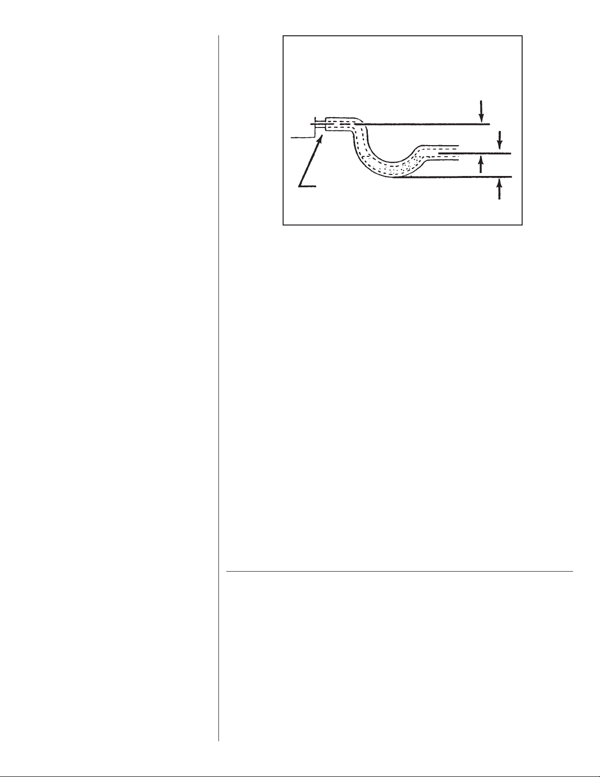
29
IMPORTANT: When making drain fitting connections to drain pan, do not overtighten.
Overtightening fittings can split pipe connetions on the drain pan.
• Install drain lines so they do not block service access to front of the unit. Minimum
clearance of 24 inches is required for filter, coil or blower removal and service access.
• Make sure unit is level or pitched slightly toward primary drain connection so that
water will drain completely from the pan. (See Figure 8.)
• Do not reduce drain line size less than connection size provided on condensate drain
pan.
• All drain lines must be pitched downward away from the unit a minimum of 1/8” per
foot of line to ensure proper drainage.
• Do not connect condensate drain line to a closed or open sewer pipe. Run condensate to an open drain or outdoors.
• The drain line should be insulated where necessary to prevent sweating and damage
due to condensate forming on the outside surface of the line.
• Make provisions for disconnecting and cleaning of the primary drain line should it
become necessary. Install a 3 in. trap in the primary drain line as close to the unit as
possible. Make sure that the top of the trap is below connection to the drain pan to
allow complete drainage of pan (See Figure 8).
• Auxiliary drain line should be run to a place where it will be noticeable if it becomes
operational. Occupant should be warned that a problem exists if water should begin
running from the auxiliary drain line.
• Plug the unused drain connection with the plugs provided in the parts bag, using a
thin layer of teflon paste, silicone or teflon tape to form a water tight seal.
• Test condensate drain pan and drain line after installation is complete. Pour water into
drain pan, enough to fill drain trap and line. Check to make sure drain pan is draining
completely, no leaks are found in drain line fittings, and water is draining from the termination of the primary drain line.
7.3 DUCT FLANGES
Field-installed duct flanges (4 pieces) are shipped with units. Install duct flanges as
needed on top of the unit. (See Figure 3.)
8.0 AIR FILTER (not factory-installed)
• External filter or other means of filtration is required. Units should be sized for a maxi-
mum of 300 feet/min. air velocity or that recommended for the type filter installed.
Filter application and placement are critical to airflow, which may affect the heating and
cooling system performance. Reduced airflow can shorten the life of the system’s major
components, such as motor, limits, elements, heat relays, evaporator coil or compressor.
Consequently, we recommend that the return air duct system have only one filter location. For systems with a return air filter grill or multiple filter grills, can have a filter
installed at each of the return air openings.
If high efficiency filters or electronic air cleaners are used in the system, it is important
that the airflow is not reduced to maximize system performance and life. Always verify
that the system’s airflow is not impaired by the filtering system that has been installed,
by performing a temperature rise and temperature drop test.
FIGURE 8
CONDENSATE DRAIN TRAP
DO NOT OPERATE UNIT WITHOUT
CONDENSATE DRAIN TRAP.
UNIT MUST BE SLIGHTLY INCLINED
TOWARD DRAIN CONNECTION.
DO NOT OVERTIGHTEN DRAIN FITTING
UNIT
3''
3''
Page 30
30
IMPORTANT: DO NOT DOUBLE FILTER THE RETURN AIR DUCT SYSTEM. DO NOT
FILTER THE SUPPLY AIR DUCT SYSTEM.
9.0 SEQUENCE OF OPERATION
9.1 COOLING (COOLING ONLY OR HEAT PUMP)
• When the thermostat “calls for cooling,” the circuit between R and G is completed,
causing the blower relay (BR) to energize. The N.O. contacts will close, causing the
indoor blower motor (IBM) to operate. The circuit between R and Y is also completed:
This circuit closes the contactor (CC) in the outdoor unit starting the compressor
(COMP) and outdoor fan motor (OFM).
9.2 HEATING (ELECTRIC HEAT ONLY)
• When the thermostat “calls for heat,” the circuit between R and W is completed, and
the heater sequencer (HR
1
) is energized. The heating elements (HE) and the indoor
blower motor (IBM) will come on. Units with a second heater sequencer (HR
2
) can be
connected with the first sequencer (HR
1
) to W on the thermostat sub-base or con-
nected to a second stage W
2
on the sub-base.
9.3 HEATING (HEAT PUMP)
• When the thermostat “calls for heat,” the circuits between R and B, R and Y and R
and G are completed. Circuit R and B energizes the reversing valve (RV) switching it
to the heating position (remains energized as long as selector switch is in “heat” position). Circuit R and Y energizes the contactor (CC) starting the outdoor fan motor
(OFM) and compressor (COMP). Circuit R and G energizes the blower relay (BR)
starting the indoor blower motor (IBM).
• If the room temperature should continue to fall, circuit R and W
2 is completed by the
second-stage heat room thermostat. Circuit R-W
2 energizes a heat sequencer (HR1).
The completed circuit will energize supplemental electric heat. Units with a second
heater sequencer (HR
2) can be connected with first sequencer (HR1) to W2 on thermo-
stat or connected to a third heating stage W
2 on the thermostat sub-base. A light on
the thermostat indicates when supplemental heat is being energized.
9.4 BLOWER TIME DELAY (HEATING OR COOLING)
• All models are equipped with a blower time delay (BTD) in lieu of a blower relay (BR)
(see wiring diagram). The blower will run for 30 seconds after the blower time delay
(BTD) is de-energized.
9.5 DEFROST (DEFROST HEAT CONTROL)
• For sequence of operation for defrost controls, see outdoor heat pump installation
instructions.
• Supplemental heat during defrost can be provided by connecting the purple (PU) pigtail in the outdoor unit to the W on the thermostat. This will complete the circuit
between R and W through a set of contacts in the defrost relay (DR) when the outdoor heat pump is in defrost. This circuit, if connected, will help prevent cold air from
being discharged from the indoor unit during defrost.
• For most economical operation, if cold air is not of concern during defrost, the purple
wire can be left disconnected. Supplemental heat will then come on only when called
for by second stage room thermostat.
!
WARNING
Do not operate the system without filters. A portion of the dust entrained in the
air may temporarily lodge in the duct runs and at the supply registers. Any circulated dust particles could be heated and charred by contact with the air handler elements. This residue could soil ceilings, walls, drapes, carpets and other
articles in the house.
Soot damage may occur with filters in place, when certain types of candles, oil
lamps or standing pilots are burned.
Page 31

31
9.6 EMERGENCY HEAT (HEATING HEAT PUMP)
• If selector switch on thermostat is set to the emergency heat position, the heat pump
will be locked out of the heating circuit, and all heating will be electric heat. Jumper
should be placed between W2 and E on the thermostat sub-base so that the electric
heat control will transfer to the first stage heat on the thermostat. This will allow the
indoor blower to cycle on and off with the electric heat when the fan switch is in the
auto position.
9.7 ROOM THERMOSTAT (ANTICIPATOR SETTING)
See instructions with outdoor section, condensing unit or heat pump for recommended
room thermostats.
• On units with one electric heat sequencer (HR
1) (see wiring diagram on unit), heat
anticipator setting should be .16.
• On units with two electric heat sequencers (HR
1 & HR2) (see wiring diagram on unit),
heat anticipator setting should be .32 if both are connected to same stage on thermostat. Setting should be .16 if (HR
1 &HR2) are connected to separate stages.
NOTE: Some thermostats contain a fixed, non-adjustable heat anticipator. Adjustment
is not permitted.
• The thermostat should be mounted 4 to 5 feet above the floor on an inside wall of the
living room or a hallway that has good air circulation from the other rooms being controlled by the thermostat. It is essential that there be free air circulation at the location
of the same average temperature as other rooms being controlled. Movement of air
should not be obstructed by furniture, doors, draperies, etc. The thermostat should
not be mounted where it will be affected by drafts, hot or cold water pipes or air ducts
in walls, radiant heat from fireplace, lamps, the sun, T.V. or an outside wall. See
instruction sheet packaged with thermostat for mounting and installation instructions.
10.0 CALCULATIONS
10.1 CALCULATING TEMPERATURE RISE
• The formula for calculating air temperature rise for electric resistance heat is:
3.16 x Watts
Temperature Rise °F =
CFM
Where: 3.16 = Constant, CFM = Airflow
10.2 CALCULATING BTUH HEATING CAPACITY
• The formula for calculating BTUH heating capacity for electric resistance heat is:
BTUH Heating = Watts x 3.412
Where: 1 kW = 1000 Watts, 3.412 = Btuh/Watt
10.3 CALCULATING AIRFLOW CFM
• The formula for calculating airflow using temperature rise and heating BTUH for units
with electric resistance heat is:
Heating BTUH
CFM =
1.08 x Temp. Rise
10.4 CALCULATING CORRECTION FACTOR
• For correction of electric heat output (kW or BTUH) or temperature rise at voltages
other than rated voltage multiply by the following correction factor:
Applied Voltage
2
Correction Factor =
Rated Voltage
2
Page 32
32
11.0 PRE-START CHECKLIST
12.0 MAINTENANCE
For continuing high performance, and to minimize possible equipment failure, it is essential that periodic maintenance be performed on this equipment. Consult your local dealer
as to the proper frequency of maintenance and the availability of a maintenance contract
IMPORTANT: Before performing any service or maintenance procedures, see the
“Safety Information” section at the front of this manual.
12.1 AIR FILTER (NOT FACTORY-INSTALLED)
Check the system filter every ninety days or as often as found to be necessary and if
obstructed, clean or replace at once.
FILTER MAINTENANCE
Have your qualified installer, service agency or HVAC professional instruct you on how
to access your filters for regular maintenance.
IMPORTANT: Do not operate the system without a filter in place.
• New filters are available from your local distributor.
!
WARNING
Units with circuit breaker(s) meet requirements as a service disconnect switch,
however, if access is required to the line side (covered) of the circuit breaker,
this side of the breaker(s) will be energized with the breaker(s) de-energized.
Contact with the line side can cause electrical shock resulting in personal
injury or death.
PRE-START CHECKLIST
Is unit properly located, level, secure and serviceable?
Has auxiliary pan been provided under the unit with
separate drain? (Units installed above a finished
ceiling).
Is condensate line properly sized, run, trapped,
pitched and tested?
Is ductwork correctly sized, run, taped and insulated?
Have all cabinet openings and wiring been sealed
with caulking?
Is the filter clean, in place and of adequate size?
Is the wiring tight, correct and to the wiring diagram?
Is the unit properly grounded and protected (fused)?
Is the thermostat heat anticipator been set properly?
Is the unit circuit breaker(s) rotated properly “on” up
- “off” down?
Are the unit circuit breaker(s) line lug cover(s) in
place?
Are all access panels in place and secure?
❍
YES
❍ NO
❍ YES
❍ NO
❍ YES
❍ NO
❍ YES
❍ NO
❍ YES
❍ NO
❍ YES
❍ NO
❍ YES
❍ NO
❍ YES
❍ NO
❍ YES
❍ NO
❍ YES
❍ NO
❍ YES
❍ NO
❍ YES
❍ NO
Refer to outdoor unit installation instructions for system
start-up instructions and refrigerant charging instructions.
Page 33
33
12.2 INDOOR COIL - DRAIN PAN - DRAIN LINE
Inspect the indoor coil once each year for cleanliness and clean as necessary. In some
cases, it may be necessary to remove the filter and check the return side of the coil with
a mirror and flashlight.
IMPORTANT: Do not use caustic household drain cleaners, such as bleach, in the condensate pan or near the indoor coil. Drain cleaners will quickly damage the indoor coil.
12.3 BLOWER MOTOR AND WHEEL
Inspect the blower motor and wheel for cleanliness. It should be several years before it
would become necessary to clean the blower motor and wheel.
• If it becomes necessary to remove the blower assembly from the unit, see instructions
on removal and disassembly of motor, blower and heater parts.
• The blower motor and wheel may be cleaned by using a vacuum with a soft brush
attachment. Remove grease with a mild solvent such as hot water and detergent. Be
careful not to disturb the balance weights (clips) on the blower wheel blades. Do not
drop or bend wheel as balance will be affected.
12.4 LUBRICATION
The blower motor sleeve bearings are pre-lubricated by the motor manufacturer and do
not have oiling ports. Motor should be run for an indefinite period of time without additional lubrication.
12.5 BLOWER ASSEMBLY REMOVAL AND REPLACEMENT
Removing the blower assembly is not required for normal service and maintenance.
Removal is necessary for replacement of defective parts such as motor, blower wheel.
After extended use, removal of the blower assembly may become necessary for a thorough cleaning of the blower motor and wheel.
• Mark field power supply wiring (for replacement) attached to terminal block or circuit
breaker(s) on blower assembly. Remove wiring from terminal block or circuit breaker(s).
• Mark low voltage control wiring (for replacement) where attached to unit control pigtails on right side of blower housing. Remove wire nuts attaching field control wiring to
unit control pigtails.
• Remove 4 screws holding blower assembly to front channel of cabinet and pull blower
assembly from cabinet.
• To replace blower assembly, slide blower assembly into blower deck. Make sure
blower assembly engages lances in deck properly. If assembly hangs up, check to
make sure top and bottom are lined up in proper locations.
• Slide blower assembly to back of cabinet and make sure it is completely engaged.
• Replace 4 screws holding blower assembly to front channel of cabinet. Take care not
to strip screws, just snug into place.
• Replace low voltage control wiring with wire nuts and make sure wiring is to wiring
diagram and a good connection has been made.
• Replace field power wiring to terminal block or circuit breaker(s) on control area of
blower assembly. Make sure wires are replaced as they were, check wiring diagram if
necessary. Tighten supply power wiring securely to terminals lugs.
• Make sure wiring is within cabinet and will not interfere with access door. Make sure
proper separation between low voltage control wiring and field power wiring has been
maintained.
• Replace blower assembly control access panel before energizing equipment.
!
WARNING
If removal of the blower assembly is required, all disconnect switches supplying power to the equipment must be de-energized and locked (if not in sight of
unit) so the field power wires can be safely removed from the blower assembly.
Failure to do so can cause electrical shock resulting in personal injury or
death.
Page 34
34
12.6 MOTOR REPLACEMENT
With the blower assembly removed, the indoor blower motor can be removed and
replaced using the following procedure:
• Remove motor leads from the motor capacitor and blower relay. Note lead locations
for ease of reassembly. Pull leads from plastic bushing in blower side.
• Loosen the set screw holding blower wheel onto the motor shaft. Shaft extends
through blower hub so that a wrench can be used on the extended shaft to break the
shaft loose if necessary. Be careful not to damage shaft. A wheel puller can be used
on the groove in the blower hub if necessary.
• Remove 4 metal screws holding motor mounts to blower side and remove motor from
blower assembly.
• To install new motor, remove 1 screw holding motor mounts to motor shell and
remove mounts (four) from motor.
• Install (four) motor mounts to motor using same screw or screws supplied with
replacement motor.
• To reassemble, insert motor shaft through hub in blower wheel and orient motor to
original position with motor leads and motor label to front of blower (control area).
• Reassemble 12 sheet metal screws through motor mounts into blower side. Do not
overtorque screws, blower side is light gage sheet metal, just snug screws tight
enough to hold motor mounts in position.
• Turn motor shaft so that flat on shaft is located under blower wheel setscrew, and
blower wheel is centered in blower housing with the same distance on each side
between the inlet venturi and outside of blower wheel. Tighten setscrew on motor
shaft. Turn wheel by hand to make sure it runs true without hitting blower sides.
• Reassemble motor wiring to capacitor and blower relay making sure that wires match
wiring diagram and are tight and secure.
12.7 BLOWER WHEEL REPLACEMENT
With the blower assembly removed and the motor assembly removed (see above
instructions), remove the 4 screws holding the blower wrap (cutoff) to the blower sides.
• With wrap (cutoff) screws removed, cut off end of blower wrap will spring up. Lifting
wrap blower wheel is removed through the discharge opening in the blower housing.
• To replace, make sure wheel is oriented properly with hub to the opposite side from
the motor. Lift blower wrap and insert blower wheel through discharge opening in the
blower housing.
• Hold blower wrap down into position and replace two screws holding blower wrap to
blower sides.
• See motor replacement and blower assembly instructions for remaining assembly
procedure.
13.0 REPLACEMENT PARTS
Any replacement part used to replace parts originally supplied on equipment must be the
same as or an approved alternate to the original part supplied. The manufacturer will not
be responsible for replacement parts not designed to physically fit or operate within the
design parameters the original parts were selected for.
These parts include but are not limited to: Circuit breakers, heater controls, heater limit
controls, heater elements, motor, motor capacitor, blower relay, control transformer,
blower wheel, filter, indoor coil and sheet metal parts.
!
WARNING
To avoid electrical shock which can result in personal injury or death, use only
the screws furnished in the motor shell mounting holds. Screws are #8-18 x .25
in. long blunt nose thread forming. Screws longer than 1/4 in. may contact the
motor winding.
Page 35
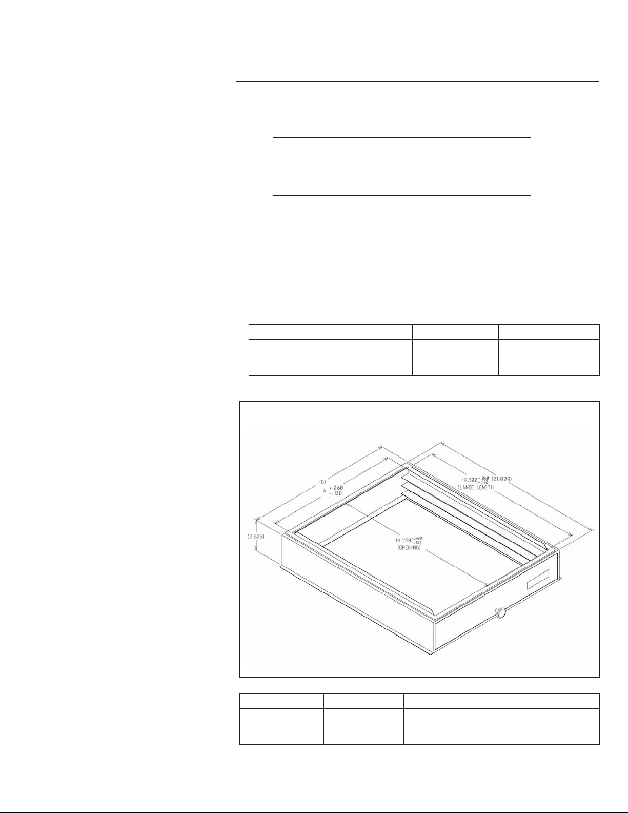
35
When ordering replacement parts, it is necessary to order by part number and include
with the order the complete model number and serial number from the unit data plate.
(See parts list for unit component part numbers).
14.0 ACCESSORIES-KITS-PARTS
• Combustible Floor Base RXHB- for downflow applications.
• Jumper Bar Kit 3 Ckt. to 1 Ckt. RXBJ-A31 is used to convert single phase multiple
three circuit units to a single supply circuit. Kit includes cover and screw for line side
terminals.
• Jumper Bar Kit 2 Ckt. to 1 Ckt. RXBJ-A21 is used to convert single phase multiple
two circuit units to a single supply circuit. Kit includes cover and screw for line side
terminals.
NOTE: No jumper bar kit is available to convert three phase multiple two circuit units
to a single supply circuit.
• External Filter Base RXHF- (See Figure 9)
• External Filter Rack: RXHF-B (See Figure 9)
Combustible Floor
Model Cabinet Size Base Model Number
17 RXHB-17
21 RXHB-21
24 RXHB-24
Model Cabinet Size Filter Size Part Number A B
17 16 x 20 [406 x 508] RXHF-17 15.70 17.50
21 20 x 20 [508 x 508] RXHF-21 19.20 21.00
24 25 x 20 [635 x 508] RXHF-24 22.70 25.50
FIGURE 9
EXTERNAL FILTER BASE: RXHF-
Accommodate
1” or 2”
filter
Model Cabinet Size Filter Size Part Number A B
17 16 x 20 RXHF-B17 16.90 20.77
21 20 x 20 RXHF-B21 20.40 20.77
24 25 x 20 RXHF-B24 25.00 21.04
Accommodate
1” filter
Page 36
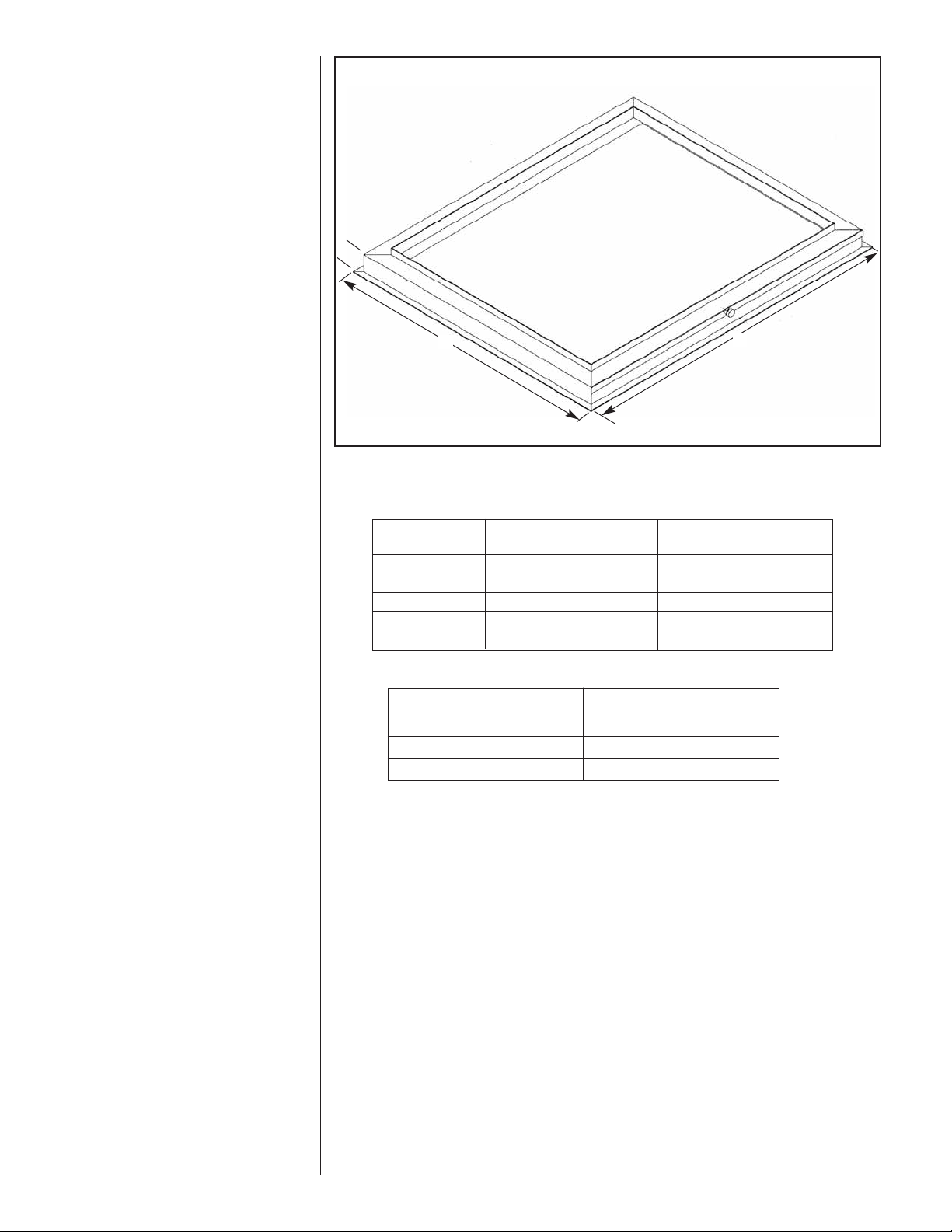
36
• Horizontal Adapter Kit RXHH-
This horizontal adapter kit is used to convert Upflow/Downflow only models to horizontal flow. See the following table to order proper horizontal adapter kit.
• Auxiliary Horizontal Overflow Pan RXBM-
Nominal Cooling
Auxiliary Horizontal
Capacity Tons
Overflow Pan Accessory
Model Number
1
1
⁄2 - 3 RXBM-AC48
3
1
⁄2 - 5 RXBM-AC61
Coil Model
Horizontal Adapter Kit Horizontal Adapter Kit
Model Number (Single Qty.) Model Number (10-pak Qty.)
2414 RXHH-A01 RXHH-A01x10
2417 RXHH-A02 RXHH-A02x10
3617/3621 RXHH-A03 RXHH-A03x10
4821/4824 RXHH-A04 RXHH-A04x10
6024 RXHH-A05 RXHH-A05x10
FIGURE 10
EXTERNAL FILTER RACK: RXHF- B17, B21, B24
B
1.50
A
➦
➦
CM 0707
 Loading...