

Rheem RHPL-HM2421JC, RHPL-HM4824JC, RHPL-HM3621JC, RHPL-HM6024JC Installation Instructions Manual
Page 1
INSTALLATION INSTRUCTIONS
WARNING
ISO 9001:2008
AIR HANDLERS
RHPL Premium High Efficiency
Equipped With The Comfort Control
2
System™
!
▲WARNING
These instructions are intended as an aid to qualified licensed
service personnel for proper installation, adjustment and
operation of this unit. Read these instructions thoroughly before
attempting installation or operation. Failure to follow these
instructions may result in improper installation, adjustment,
service or maintenance possibly resulting in fire, electrical
shock, property damage, personal injury or death.
SUPERSEDES 92-20521-45-04
92-20521-45-05
Page 2

CONTENTS
1.0 SAFETY INFORMATION. . . . . . . . . . . . . . . . . . . . . . . . . . . . . . . . . . . . . . . . 3
2.0 GENERAL INFORMATION . . . . . . . . . . . . . . . . . . . . . . . . . . . . . . . . . . . . . . 5
2.1 Important Information About Efficiency and Indoor Air Quality . . . . . . . 5
2.2 Receiving. . . . . . . . . . . . . . . . . . . . . . . . . . . . . . . . . . . . . . . . . . . . . . . . 7
2.3 Model Number Explanation . . . . . . . . . . . . . . . . . . . . . . . . . . . . . . . . . . 7
2.4 Dimensions and Weights. . . . . . . . . . . . . . . . . . . . . . . . . . . . . . . . . . . . 8
2.5 Clearances. . . . . . . . . . . . . . . . . . . . . . . . . . . . . . . . . . . . . . . . . . . . . . . 9
3.0 APPLICATIONS. . . . . . . . . . . . . . . . . . . . . . . . . . . . . . . . . . . . . . . . . . . . . . 10
3.1 Zoning Systems . . . . . . . . . . . . . . . . . . . . . . . . . . . . . . . . . . . . . . . . . . 10
3.2 Vertical Upflow & Horizontal Left . . . . . . . . . . . . . . . . . . . . . . . . . . . . . 10
3.3 Vertical Downflow & Horizontal Right . . . . . . . . . . . . . . . . . . . . . . . . . 10
3.4 Installation In An Unconditioned Space. . . . . . . . . . . . . . . . . . . . . . . . 12
4.0 ELECTRICAL WIRING . . . . . . . . . . . . . . . . . . . . . . . . . . . . . . . . . . . . . . . . 13
4.1 Power Wiring . . . . . . . . . . . . . . . . . . . . . . . . . . . . . . . . . . . . . . . . . . . . 13
4.2 Grounding . . . . . . . . . . . . . . . . . . . . . . . . . . . . . . . . . . . . . . . . . . . . . . 13
4.3 Copper Wire Size. . . . . . . . . . . . . . . . . . . . . . . . . . . . . . . . . . . . . . . . . 13
4.4 Blower Motor Electrical Data . . . . . . . . . . . . . . . . . . . . . . . . . . . . . . . . 13
4.5 Electric Heat Electrical Data . . . . . . . . . . . . . . . . . . . . . . . . . . . . . . . . 14
5.0 AIR HANDLER Comfort Control
BOARD . . . . . . . . . . . . . . . . . . . . . . . . . . . . . . . . . . . . . . . . . . . . . . . . . . . . 15
5.1 Comfort Control
5.2 Comfort Control
2
System™ Control Wiring . . . . . . . . . . . . . . . . . . . . . 15
2
Control Board. . . . . . . . . . . . . . . . . . . . . . . . . . . . . . 16
5.3 Using the On-Board LED to Determine Blower CFM. . . . . . . . . . . . . . 16
5.4 Airflow Adjustments with the Comfort Control
5.5 Cooling Airflow Settings (by Tonnage). . . . . . . . . . . . . . . . . . . . . . . . . 17
5.6 Cooling Airflow Adjustment . . . . . . . . . . . . . . . . . . . . . . . . . . . . . . . . . 17
5.7 Heating Airflow Adjustment . . . . . . . . . . . . . . . . . . . . . . . . . . . . . . . . . 17
5.8 Electric Heat Airflow. . . . . . . . . . . . . . . . . . . . . . . . . . . . . . . . . . . . . . . 18
5.9 Cooling Mode Dehumidification. . . . . . . . . . . . . . . . . . . . . . . . . . . . . . 18
5.10 Cooling Delay Profiles . . . . . . . . . . . . . . . . . . . . . . . . . . . . . . . . . . . . . 18
5.11 Conventional 24VAC Thermostat Control Wiring. . . . . . . . . . . . . . . . . 21
5.12 Using the On-Board LED to Determine Blower CFM. . . . . . . . . . . . . . 21
5.13 Cooling Airflow Settings. . . . . . . . . . . . . . . . . . . . . . . . . . . . . . . . . . . . 21
5.14 Cooling Airflow Adjustments with Single Stage Condensing Units . . . 22
5.15 Heating Airflow Adjustment . . . . . . . . . . . . . . . . . . . . . . . . . . . . . . . . . 22
5.16 Airflow Adjustment (Trim). . . . . . . . . . . . . . . . . . . . . . . . . . . . . . . . . . . 23
5.17 Electric Heat Airflow. . . . . . . . . . . . . . . . . . . . . . . . . . . . . . . . . . . . . . . 23
5.18 Cooling Mode Dehumidification. . . . . . . . . . . . . . . . . . . . . . . . . . . . . . 23
5.19 Cooling Delay Profiles . . . . . . . . . . . . . . . . . . . . . . . . . . . . . . . . . . . . . 24
5.20 Air Handler Diagnostic Codes . . . . . . . . . . . . . . . . . . . . . . . . . . . . . . . 24
6.0 DUCTWORK . . . . . . . . . . . . . . . . . . . . . . . . . . . . . . . . . . . . . . . . . . . . . . . . 26
7.0 REFRIGERANT CONNECTIONS . . . . . . . . . . . . . . . . . . . . . . . . . . . . . . . . 27
7.1 TEV Sensing Bulb . . . . . . . . . . . . . . . . . . . . . . . . . . . . . . . . . . . . . . . . 27
7.2 Condensate Drain Tubing . . . . . . . . . . . . . . . . . . . . . . . . . . . . . . . . . . 27
7.3 Duct Flanges . . . . . . . . . . . . . . . . . . . . . . . . . . . . . . . . . . . . . . . . . . . . 28
8.0 AIR FILTER . . . . . . . . . . . . . . . . . . . . . . . . . . . . . . . . . . . . . . . . . . . . . . . . . 28
9.0 AIRFLOW PERFORMANCE . . . . . . . . . . . . . . . . . . . . . . . . . . . . . . . . . . . . 28
9.1 Airflow Performance Data . . . . . . . . . . . . . . . . . . . . . . . . . . . . . . . . . . 29
10.0 SEQUENCE OF OPERATION. . . . . . . . . . . . . . . . . . . . . . . . . . . . . . . . . . . 29
10.1 Cooling (cooling only or heat pump) . . . . . . . . . . . . . . . . . . . . . . . . . . 29
10.2 Heating (electric heat only) . . . . . . . . . . . . . . . . . . . . . . . . . . . . . . . . . 29
10.3 Defrost . . . . . . . . . . . . . . . . . . . . . . . . . . . . . . . . . . . . . . . . . . . . . . . . . 29
10.4 Emergency Heat (Heating of Heat Pump) . . . . . . . . . . . . . . . . . . . . . . 29
11.0 CALCULATIONS. . . . . . . . . . . . . . . . . . . . . . . . . . . . . . . . . . . . . . . . . . . . . 30
11.1 Calculating Temperature Rise . . . . . . . . . . . . . . . . . . . . . . . . . . . . . . . 30
11.2 Calculating BTUH Heating Capacity . . . . . . . . . . . . . . . . . . . . . . . . . . 30
11.3 Calculating Airflow CFM. . . . . . . . . . . . . . . . . . . . . . . . . . . . . . . . . . . . 30
11.4 Calculating Correction Factor . . . . . . . . . . . . . . . . . . . . . . . . . . . . . . . 30
12.0 PRE-START CHECKLIST. . . . . . . . . . . . . . . . . . . . . . . . . . . . . . . . . . . . . . 31
13.0 MAINTENANCE. . . . . . . . . . . . . . . . . . . . . . . . . . . . . . . . . . . . . . . . . . . . . . 31
13.1 Air Filter . . . . . . . . . . . . . . . . . . . . . . . . . . . . . . . . . . . . . . . . . . . . . . . . 31
13.2 Indoor Coil/Drain Pan/Drain Line. . . . . . . . . . . . . . . . . . . . . . . . . . . . . 31
13.3 Comfort Control
2
System™ Board Replacement. . . . . . . . . . . . . . . . . 32
13.4 Blower Motor & Wheel. . . . . . . . . . . . . . . . . . . . . . . . . . . . . . . . . . . . . 32
13.5 Lubrication . . . . . . . . . . . . . . . . . . . . . . . . . . . . . . . . . . . . . . . . . . . . . . 33
13.6 Blower Assembly Removal & Replacement. . . . . . . . . . . . . . . . . . . . . 33
13.7 Motor Replacement . . . . . . . . . . . . . . . . . . . . . . . . . . . . . . . . . . . . . . . 33
13.8 ECM Control Module Replacement . . . . . . . . . . . . . . . . . . . . . . . . . . . 34
13.9 Blower Wheel Replacement. . . . . . . . . . . . . . . . . . . . . . . . . . . . . . . . . 34
14.0 REPLACEMENT PARTS. . . . . . . . . . . . . . . . . . . . . . . . . . . . . . . . . . . . . . . 35
15.0 ACCESSORIES - KITS - PARTS . . . . . . . . . . . . . . . . . . . . . . . . . . . . . . . . 35
2
System™ INTERFACE
2
System™ . . . . . . . . . . 16
2
Page 3
1.0 SAFETY INFORMATION
WARNING
!
Duct leaks can create an unbalanced system and draw pollutants such as dirt,
dust, fumes and odors into the home causing property damage. Fumes and
odors from toxic, volatile or flammable chemicals, as well as automobile
exhaust and carbon monoxide (CO), can be drawn into the living space
through leaking ducts and unbalanced duct systems causing personal injury
or death (see Figure 1).
• If air-moving equipment or ductwork is located in garages or off-garage storage areas - all joints, seams, and openings in the equipment and duct must
be sealed to limit the migration of toxic fumes and odors including carbon
monoxide from migrating into the living space.
• If air-moving equipment or ductwork is located in spaces containing fuel
burning appliances such as water heaters or boilers - all joints, seams, and
openings in the equipment and duct must also be sealed to prevent depressurization of the space and possible migration of combustion byproducts
including carbon monoxide into the living space.
WARNING
!
The first 36 inches of supply air plenum and ductwork must be constructed of
sheet metal as required by NFPA 90B. The supply air plenum or duct must
have a solid sheet metal bottom directly under the unit with no openings, registers or flexible air ducts located in it. If flexible supply air ducts are used they
may be located only in the vertical walls of a rectangular plenum, a minimum
of 6 inches from the solid bottom. Metal plenum or duct may be connected to
the combustible floor base, if not, it must be connected to the unit supply duct
flanges such that combustible floor or other combustible material is not
exposed to the supply air opening from the downflow unit. Exposing combustible (non-metal) material to the supply opening of a downflow unit can
cause a fire resulting in property damage, personal injury or death.
Exceptions to downflow warnings:
• Installations on concrete floor slab with supply air plenum and ductwork
completely encased in not less than 2 inches of concrete (See NFPA 90B).
!
WARNING (SEE WARNINGS IN REGARD TO DUCTWORK)
Do not install this unit in manufactured (mobile) homes. Improper installation
is more likely in manufactured housing due to ductwork material, size, location, and arrangement. Installations in manufactured housing can cause a fire
resulting in property damage, personal injury or death.
EXCEPTION
mentation by a recognized inspection authority that the installation has been
made in compliance with the instructions and all warnings have been
observed.
!
WARNING (SEE SECTION 3.2: VERTICAL UPFLOW & HORIZONTAL LEFT)
If unit is to be installed without an indoor coil, return air duct, or plenum, it must
not be installed directly over combustible material. If installed without an indoor
coil with a return duct or plenum, the air plenum or duct must have a solid sheet
metal bottom with no return air openings, registers or flexible air ducts located
directly under the unit. Exposing combustible material to the return opening of
an upflow unit without an indoor coil can cause a fire resulting in property damage, personal injury or death.
!
WARNING (SEE SECTION 13.7: ECM CONTROL MODULE REPLACEMENT)
Always have 240 volt power turned off to the furnace before attempting any
replacement of the motor or control module. Failure to do so may result in serious equipment damage, personal injury or death.
WARNING (SEE SECTION 4.0: ELECTRICAL WIRING)
!
Disconnect all power to unit before installing or servicing. More than one
disconnect switch may be required to de-energize the equipment.
Hazardous voltage can cause severe personal injury or death.
: Manufactured housing installations are approved only with docu-
Continued on next page ➜
3
Page 4
!
WARNING (SEE SECTION 4.3: GROUNDING)
The unit must be permanently grounded. Failure to do so can result in electrical shock causing personal injury or death.
!
WARNING (SEE SECTION 13.0: MAINTENANCE)
Units with circuit breaker(s) meet requirements as a service disconnect
switch, however, if access is required to the line side (covered) of the circuit
breaker, this side of the breaker(s) will be energized with the breaker(s) deenergized. Contact with the line side can cause electrical shock resulting in
personal injury or death.
!
WARNING (SEE SECTION 13.5: BLOWER ASSEMBLY REMOVAL & REPLACEMENT)
If removal of the blower assembly is required, all disconnect switches supplying power to the airhandler must be de-energized and locked (if not in sight of
unit) so the field power wires can be safely removed from the blower assembly. Failure to do so can cause electrical shock resulting in personal injury or
death.
WARNING
!
PROPOSITION 65: This appliance contains fiberglass insulation. Respirable
particles of fiberglass are known to the State of California to cause cancer.
All manufacturer products meet current Federal OSHA Guidelines for safety.
California Proposition 65 warnings are required for certain products, which are
not covered by the OSHA standards.
California's Proposition65 requires warnings for products sold in California
that contain or produce any of over 600 listed chemicals known to the State of
California to cause cancer or birth defects such as fiberglass insulation, lead in
brass, and combustion products from natural gas.
All “new equipment” shipped for sale in Californiawill have labels stating that
the product contains and/or produces Proposition65 chemicals. Although we
have not changed our processes, having the same label on all our products
facilitates manufacturing and shipping. We cannot always know “when, or if”
products will be sold in the California market.
You may receive inquiries from customers about chemicals found in, or produced by, some of our heating and air-conditioningequipment, or found in natural gas used with some of our products. Listed below are those chemicals and
substances commonly associated with similar equipment in our industry and
other manufacturers.
• GlassWool (Fiberglass) Insulation
• Carbon Monoxide (CO).
• Formaldehyde
• Benzene
More details are available at the websites for OSHA (Occupational Safety and
Health Administration), at www.osha.gov
(Office of Environmental Health Hazard Assessment), at www.oehha.org.
Consumer education is important since the chemicals and substances on the
list are found in our daily lives. Most consumers are aware that products present safety and health risks, when improperly used, handled and maintained.
and the State of California’s OEHHA
!
WARNING (SEE SECTION 6.0: DUCTWORK)
Do not, under any circumstances, connect return ductwork to any other heat
producing device such as fireplace insert, stove, etc. Unauthorized use of
such devices may result in fire, carbon monoxide poisoning, explosion, personal injury or property damage.
!
WARNING
Because of possible damage to equipment or personal injury, installation, service, and maintenance should be performed by trained, qualified service personnel. Consumer service is recommended only for filter cleaning/replacement. Never operate the unit with the access panels removed.
Continued on next page ➜
4
Page 5
WARNING (SEE SECTION 3.3: VERTICAL DOWNFLOW & HORIZONTAL RIGHT)
!
The RXHB-17, RXHB-21, or RXHB-24 combustible floor base is required when
certain units are applied downflow on combustible flooring. Failure to use the
base can cause a fire resulting in property damage, personal injury or death.
See clearances
section in this manual for combustible floor base RXHB-.
!
CAUTION (SEE SECTION 13.7: ECM CONTROL MODULE REPLACEMENT)
Reversing the 5-pin connector on the ECM motor causes immediate failure of
the control module.
for units requiring a combustible floor base. See the accessory
CAUTION (SEE SECTION 3.2: VERTICAL UPFLOW & HORIZONTAL LEFT)
Horizontal units must be configured for right hand air supply. Horizontal drain
pan must be located under indoor coil. Failure to use the drain pan can result
in property damage.
CAUTION (SEE SECTION 13.2: INDOOR COIL - DRAIN PAN - DRAIN LINE)
In compliance with recognized codes, it is recommended that an auxiliary
drain pan be installed under all evaporator coils or units containing evaporator
coils that are located in any area of a structure where damage to the building
or building contents may occur as a result of an overflow of the coil drain pan
or a stoppage in the primary condensate drain piping. See accessory section
in this manual for secondary horizontal drain pan RXBM-.
NOTICE
!
When used on cooling applications, excessive sweating may occur when unit
is installed in an unconditioned space. This can result in property damage.
NOTICE
!
Improper installation, or installation not made in accordance with the
Underwriters Laboratory (UL) certification or these instructions, can result
in unsatisfactory operation and/or dangerous conditions and are not covered by the unit warranty.
NOTICE
!
In compliance with recognized codes, it is recommended that an auxiliary
drain pan be installed under all evaporator coils or units containing evaporator coils that are located in any area of a structure where damage to the
building or building contents may occur as a result of an overflow of the
coil drain pan or a stoppage in the primary condensate drain piping. See
accessories section of these instructions for auxiliary horizontal overflow
pan information (model RXBM).
2.0 GENERAL INFORMATION
2.1 IMPORTANT INFORMATION ABOUT EFFICIENCY AND INDOOR
2.1 AIR QUALITY
Central cooling and heating equipment is only as efficient as the duct system that carries the cooled or heated air. To maintain efficiency, comfort and good indoor air quality,
it is important to have the proper balance between the air being supplied to each room
and the air returning to the cooling and heating equipment.
5
Page 6
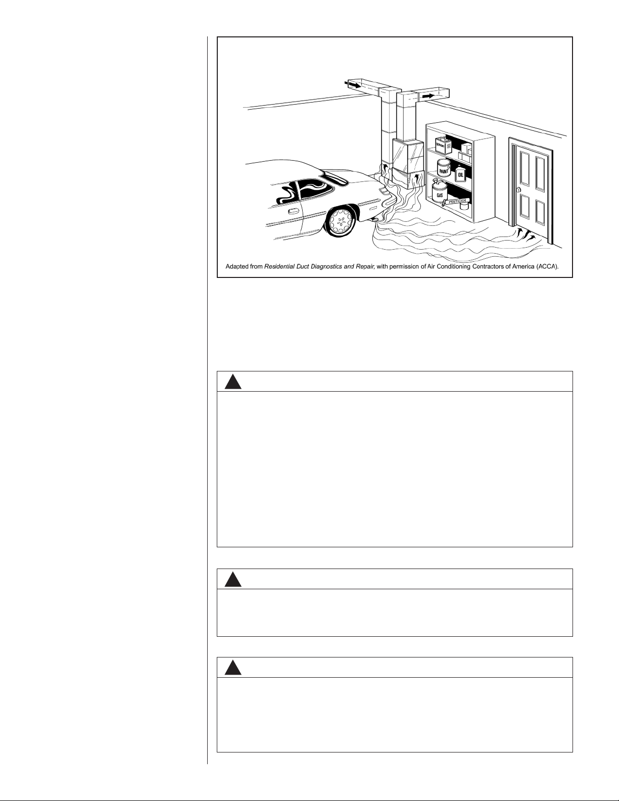
FIGURE 1
MIGRATION OF DANGEROUS SUBSTANCES, FUMES, AND ODORS INTO LIVING SPACES
Proper balance and sealing of the duct system improves the efficiency of the heating
and air conditioning system and improves the indoor air quality of the home by reducing
the amount of airborne pollutants that enter homes from spaces where the ductwork
and/or equipment is located. The manufacturer and the U.S. Environmental Protection
Agency’s Energy Star Program recommend that central duct systems be checked by a
qualified contractor for proper balance and sealing.
WARNING
!
Duct leaks can create an unbalanced system and draw pollutants such as
dirt, dust, fumes and odors into the home causing property damage.
Fumes and odors from toxic, volatile or flammable chemicals, as well as
automobile exhaust and carbon monoxide (CO), can be drawn into the living space through leaking ducts and unbalanced duct systems causing
personal injury or death (see Figure 1).
• If air-moving equipment or ductwork is located in garages or off-garage
storage areas - all joints, seams, and openings in the equipment and
duct must be sealed to limit the migration of toxic fumes and odors
including carbon monoxide from migrating into the living space.
• If air-moving equipment or ductwork is located in spaces containing fuel
burning appliances such as water heaters or boilers - all joints, seams,
and openings in the equipment and duct must also be sealed to prevent
depressurization of the space and possible migration of combustion
byproducts including carbon monoxide into the living space.
NOTICE
!
Improper installation, or installation not made in accordance with the
Underwriters Laboratory (UL) certification or these instructions, can result in
unsatisfactory operation and/or dangerous conditions and are not covered by
the unit warranty.
NOTICE
!
In compliance with recognized codes, it is recommended that an auxiliary
drain pan be installed under all evaporator coils or units containing evaporator
coils that are located in any area of a structure where damage to the building
or building contents may occur as a result of an overflow of the coil drain pan
or a stoppage in the primary condensate drain piping. See accessories section
of these instructions for auxiliary horizontal overflow pan information (model
RXBM).
6
Page 7
2.2 RECEIVING
Immediately upon receipt, all cartons and contents should be inspected for transit damage. Units with damaged cartons should be opened immediately. If damage is found, it
should be noted on the delivery papers, and a damage claim filed with the last carrier.
• Afterunit has been deliveredto jobsite,removecarton taking care not to damage unit.
• Check the unit rating plate for unit size, electric heat, coil, voltage, phase, etc. to be
sure equipment matches what is required for the job specification.
• Read the entire instructions before starting the installation.
• Some building codes require extra cabinet insulation and gasketing when unit is
installed in attic applications.
• If installed in an unconditioned space, apply caulking around the power wires, control
wires, refrigerant tubing and condensate line where they enter the cabinet. Seal the
power wires on the inside where they exit conduit opening. Caulking is required to
pre-vent air leakage into and condensate from forming inside the unit, control box,
and on electrical controls.
• Install the unit in such a way as to allow necessary access to the coil/filter rack and
blower/control compartment.
• Install the unit in a level position to ensure proper condensate drainage. Make sure
unit is level in both directions within 1/8”.
• Install the unit in accordance with any local code which may apply and the national
codes. Latest editions are available from: “National Fire Protection Association, Inc.,
Batterysmarch Park, Quincy, MA 02269.” These publications are:
• ANSI/NFPA No. 70-(Latest Edition) National Electrical Code.
• NFPA90A Installation of Air Conditioning and Ventilating Systems.
• NFPA90B Installation of warm air heating and air conditioning systems.
• The equipment has been evaluated in accordance with the Code of Federal
Regulations, Chapter XX, Part 3280.
2.3 MODEL NUMBER EXPLANATION (SEE FIGURE 2)
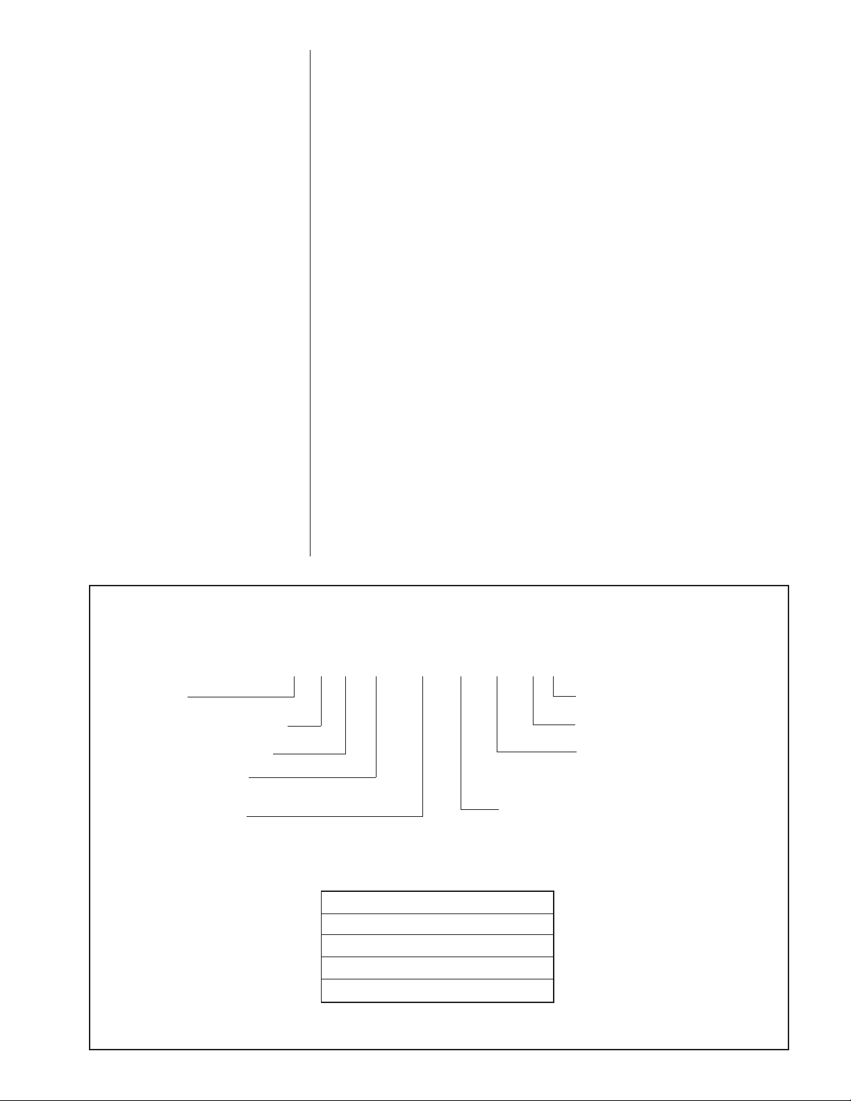
FIGURE 2
MODEL NUMBER EXPLANATION
RHPL–HM 24 21 JC
TRADEBRAND
CLASSIFICATION = AIR HANDLER
P = 16 SEER PREMIUM MODEL
L = R-410A REFRIGERANT
HM = A/C OR HEAT PUMP
MULTI-POSITION (Upflow &
Horizontal Left Is The Factory
Configuration)
AVAILABLE MODELS
RHPL-HM2421JC
RHPL-HM3621JC
RHPL-HM4824JC
RHPL-HM6024JC
DESIGN VARIATION
C = EQUIPPED WITH THE Comfort
C = Control
VOLTAGE
J = 208/240/1/60
CABINET SIZE
21 = 21" (600-1200 CFM)
24 = 24.5" (1200-1700 CFM)
CAPACITY
24 = 18000/24000 BTUH 48 = 42000/48000 BTUH
36 = 30000/36000 BTUH 60 = 60000 BTUH
2
System™
7
Page 8
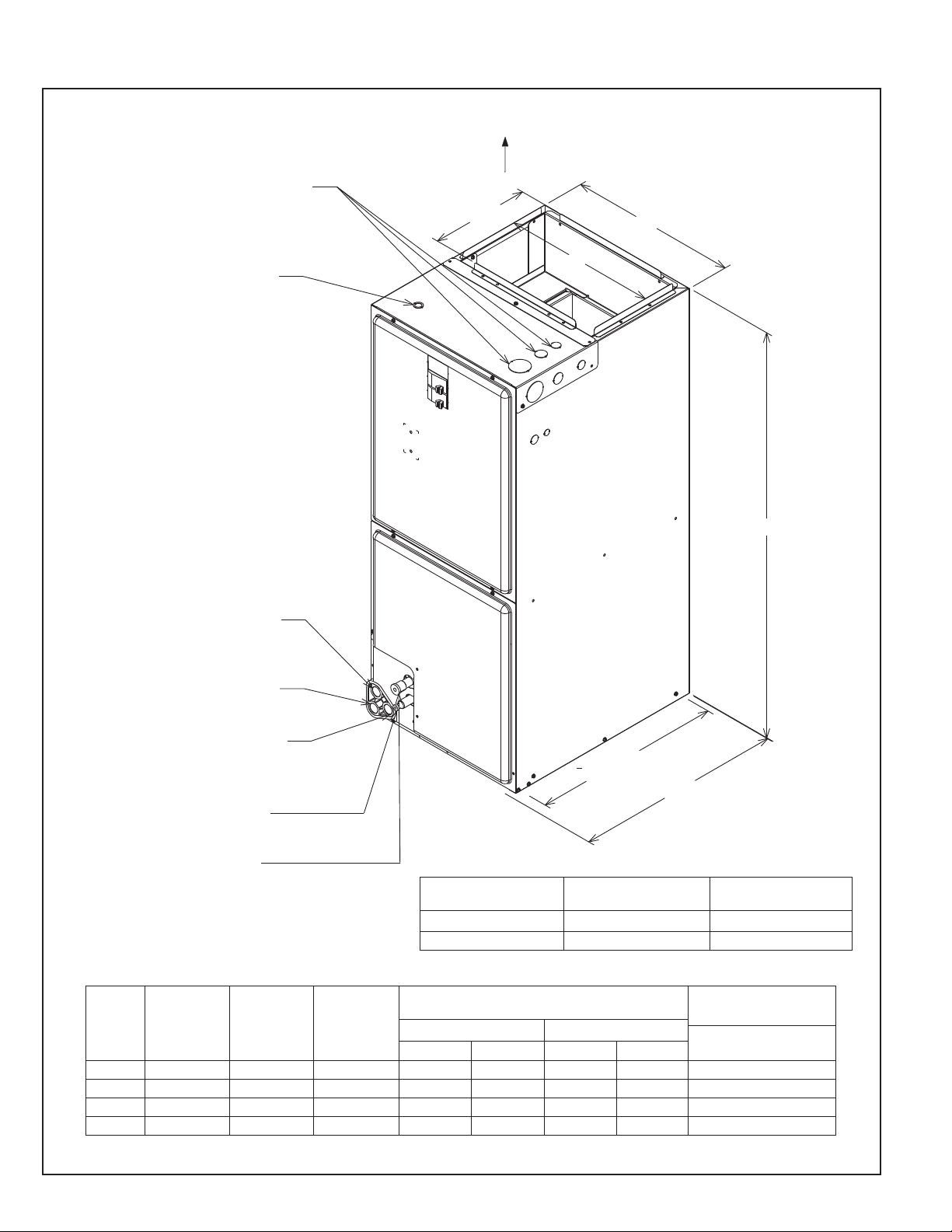
2.4 DIMENSIONS & WEIGHTS (SEE FIGURE 3)
FIGURE 3
DIMENSIONS AND WEIGHTS -- SINGLE COIL UNITS
ELECTRICAL CONNECTIONS
MAY EXIT TOP OR EITHER SIDE
HIGH VOLTAGE CONNECTION 7/8".
1 3/32", 1 31/32" DIA. KNOCK OUTS.
LOW VOLTAGE CONNECTION
5/8" AND 7/8" KNOCK OUT
NOTE: 24" CLEARANCE REQUIRED
IN FRONT OF UNIT FOR FILTER
AND COIL MAINTENANCE.
SUPPLY AIR
105/16
W
A
AUXILIARY DRAIN CONNECTION
3/4" FEMALE PIPE THREAD (NPT)
HORIZONTAL APPLICATION ONLY
PRIMARY DRAIN CONNECTION
3/4" FEMALE PIPE THREAD (NPT)
AUXILIARY DRAIN CONNECTION
3/4" FEMALE PIPE THREAD (NPT)
UPFLOW/DOWNFLOW APPLICATION
ONLY
LIQUID LINE CONNECTION
COPPER (SWEAT)
VAPOR LINE CONNECTION
COPPER (SWEAT)
UPFLOW UNIT SHOWN;
UNIT MAY BE INSTALLED UPFLOW, DOWNFLOW.
HORIZONTAL RIGHT, OR LEFT AIR SUPPLY.
DIMENSIONAL DATA
H
191/2
RETURN AIR OPENING
2111/16
RETURN AIR OPENING DIMENSIONS
Model Return Air Opening Return Air Opening
Cabinet Size Width (Inches) Depth/Length (Inches)
3
21 19
⁄8 191⁄2
24 227⁄8 191⁄2
A-1038-01
RHPL-HM
2421 21 [533] 42 1/2 [1080] 19 1/2 [495] 480 [227] 625 [295] 640 [302] 775 [366] 92 / 106 [42 / 48]
3621 21 [533] 42 1/2 [1080] 19 1/2 [495] 720 [340] 900 [425] 960 [453] 1200 [566] 92 / 106 [42 / 48]
4824 24 1/2 [622] 55 1/2 [1410] 23 [584] 960 [453] 1200 [566] 1280 [604] 1625 [767] 162 / 180 [73 / 82]
6024 24 1/2 [622] 55 1/2 [1410] 23 [584] 1040 [491] 1375 [649] 1360 [642] 1675 [791] 181 / 198 [82 / 90]
*Maximum dehumidification airflow. Refer to Section 5.0 ECM Motor Interface Control Board, for more information.
UNIT WIDTH
“W” IN. [mm]
UNIT HEIGHT
“H” IN. [mm]
SUPPLY DUCT
“A” IN. [mm]
NOMINAL COIL AIRFLOW [L/s]
ST
STAGE 2NDSTAGE
1
ODD* ODD*Normal Normal
8
UNIT WEIGHT / SHIPPING
WEIGHT (LBS.) [kg]
UNIT WITH COIL
(MAX. Kw.)
Page 9
2.5 CLEARANCES
• All units are designed for “0” inches clearance to combustible material on all cabinet
surfaces.
• Units with electric heat require a one inch clearance to combustible material for the
first three feet of supply plenum and ductwork.
• Some units require a combustible floor base depending on the heating kW. The fol-
lowing table should be used to determine these requirements:
Model Cabinet Size 21 24
Maximum Model Designation kW 18 20
Additionally, if these units are installed down-flow, a combustible floor base is
required. See Accessories for Combustible Floor Base RXHB-XX.
Units with electric heating kW equal to
not require a combustible floor base.
• Vertical units require clearance on at least one side of the unit for electrical connec-
tions. Horizontal units require clearance on either top or bottom for electrical connections. Refrigerant and condensate drain connections are made on the front of the unit.
(See Figure 4.)
• All units require 24 inches maximum access to the front of the unit for service.
• These units may be installed in either ventilated or nonventilated spaces.
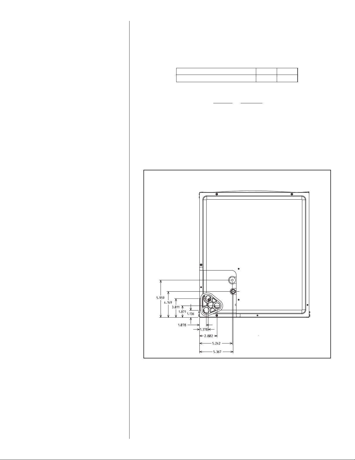
FIGURE 4
DIMENSIONS FOR FRONT CONNECT COIL
or less than the values listed in the table do
9
Page 10
3.0 APPLICATIONS
3.1 ZONING SYSTEMS
The manufacturer does not currently provide or supportzoning. However, zoning systems
can be installed with a variable speed air-handler as long as the zoning equipment manufacturers specificationsand installationinstructions are met and followed.
The preferred zoning method is to use a “bypass” system which is properly installed for
maximum efficiency. In these systems, excess air is routed back through the system to
be used again – this is opposed to a “dump” system in which excess air is routed to a
zone where it is expected that the extra heat or cooling would be least noticed.
If installed as a “bypass” system, the installation must have an optional freeze stat
installed to prevent the coil from icing with excess bypass cooling. Also, if the zoning
equipment manufacturer provides a limit switch (usually provided by the zoning manufacturer), this limit must be installed in the system to prevent the furnace from overheating.
3.2 VERTICAL UPFLOW AND HORIZONTAL LEFT
The air handler unit is factory shipped for vertical upflow and horizontal left application.
• If return air is to be ducted, install duct flush with floor. Use fireproof resilient gasket 1/8
to 1/4 in. thick between duct, unit and floor. Set unit on floor over opening.
• Support along the length of the unit, all units installed horizontally. Do not support or
suspend unit from both ends without support in the center of the cabinet. If unit is to
be supported or suspended from corners, run two reinforcing rails length of unit and
support or suspend from reinforcing rails.
• Secondary drain pan kits RXBM- are required when the unit is configured for the horizontal left position over a finished ceiling and/or living space. (See Section 15.0:
Accessories - Kits - Parts.)
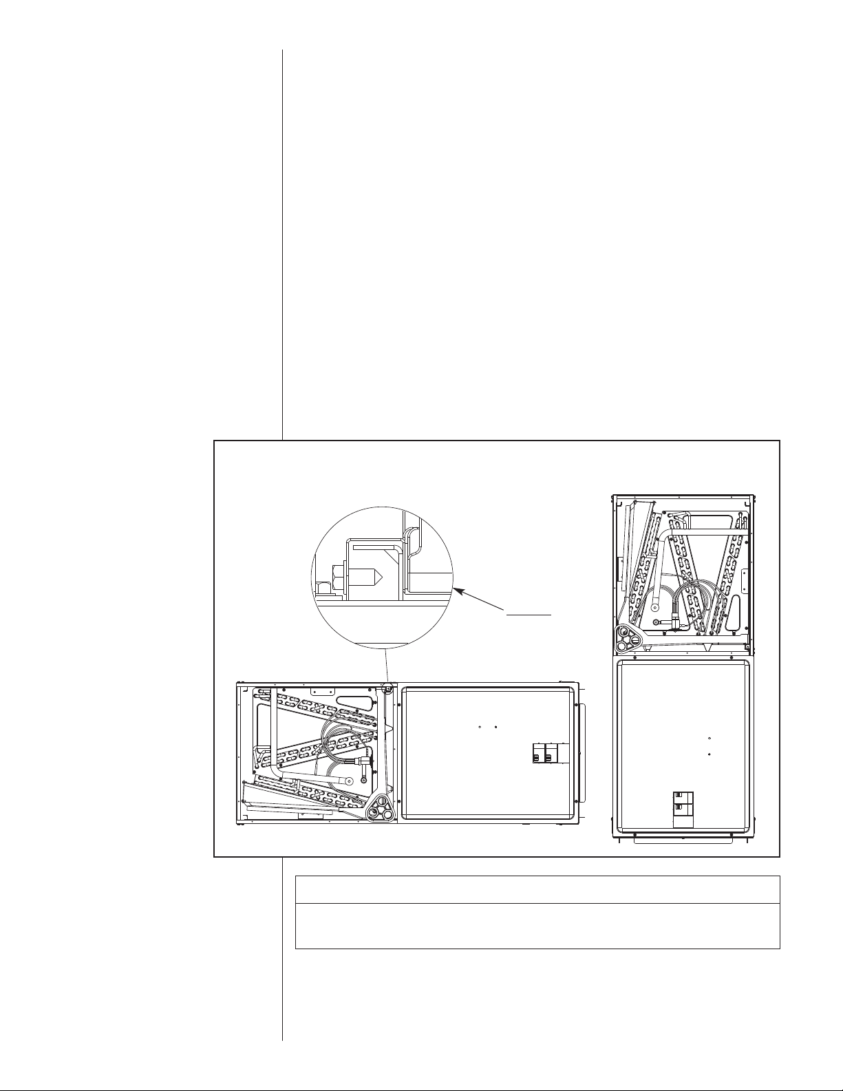
FIGURE 5
VERTICAL DOWNFLOW & HORIZONTAL RIGHT APPLICATIONS
DETAIL A
ENSURE THE RETAIN-
ING CHANNEL IS FULLY
ENGAGED WITH THE
COIL RAIL.
CAUTION
Horizontal units must be configured for right hand air supply. Horizontal drain
pan must be located under indoor coil. Failure to use the drain pan can result
in property damage.
3.3 VERTICAL DOWNFLOW AND HORIZONTAL RIGHT
Conversion to Vertical Downflow/Horizontal Right: A vertical upflow unit may be converted to vertical downflow/horizontal right. (See Figure 5.)
10
Page 11
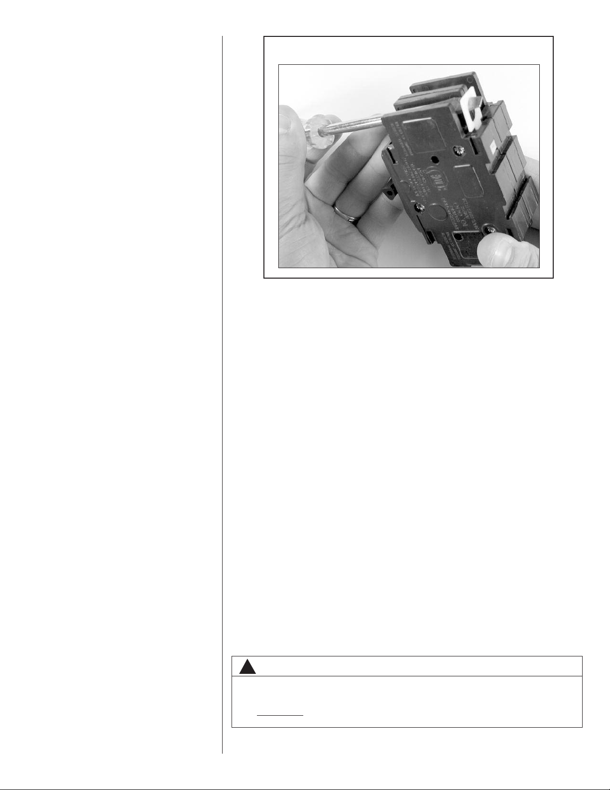
FIGURE 6
ROTATING CIRCUIT BREAKER
• Remove the indoor coil.
• Rotate the circuit breaker(s) (if in the horizontal right position) 180° (see instructions for
rotating breaker(s) that follow).
IMPORTANT: To comply with certification agencies and the National Electric Code,
units with circuit breaker(s) on vertical units must have circuit breakers installed so that
the breaker switch “on” position and marking is up and, “off” position and marking is
down.
- To turn breaker(s): Rotate one breakerpair (circuit) at a time starting with the one on the
right. Loosen both lugs on theload side of thebreaker. Wires are bundles with wire ties,
onebundlegoingto the rightlug andone bundle goingto theleft lug.
- Using a screwdriver or pencil, lift white plastic tab with hole away from breaker until
breakerreleases frommountingopening(see Figure6).
- Withbreakerheld in hand,rotatebreaker so that “on”position is up,“off” positionis down
with unit in planned vertical mounting position. Insert right wire bundle into top right
breakerlug, ensuring all strands of allwires are insertedfully intolug, and no wire insulationis in lug.
- Tighten lug as tight as possible while holding circuit breaker.Check wires and makesure
each wire is secure and none are loose. Repeat for left wire bundle in left top circuit
breakerlug.
- Replace breaker by inserting breaker mounting tab opposite white pull tab in opening,
hookmountingtab overedge in opening.
- With screwdriver or pencil, pull white tab with hole away from breaker while setting that
sideof breakerinto opening. When breaker is in place,releasetab, locking circuit breakerinto locationin opening.
- Repeat aboveoperationfor remaining breaker(s) (ifmore thanone is provided).
- Replace single point wiring jumper bar, if it is used, on line side of breaker and tighten
securely.
- Double check wires and lugs to make sure all are secure and tight. Check to make sure
unitwiring to circuitbreakerloadlugs matchthatshown onthe unitwiringdiagram.
!
WARNING
The RXHB-17, RXHB-21, or RXHB-24 combustible floor base is required when
certain units are applied downflow on combustible flooring. Failure to use the
base can cause a fire resulting in property damage, personal injury or death.
See clearances for units requiring a combustible floor base. See the accessory
section in this manual for combustible floor base RXHB-.
11
Page 12
• Rotate unitintothe downflowposition, withthe coilcompartment on topand the blowercompartmenton bottom.
• A second set of coil rails must be field installed for vertical down-flow and horizontal
right applications. Fastener clearance holes will need to be drilled in the cabinet sides
(proper hole locations are marked with “dimples” for this purpose). Note that the shorter
(no notch) coil rail must be mounted on the left-hand side to provide clearance for the
drain-pan condensate connection boss.
• Reinstall the indoor coil 180° from original position. Ensure the retaining channel is fully
engagedwith thecoil rail. (SeeFigure5, Detail A.)
• Secondary drain pan kits RXBM- are required when the unit is configured for the horizontal right position over a finished ceiling and/or living space. (See Section 15.0:
Accessories - Kits - Parts.)
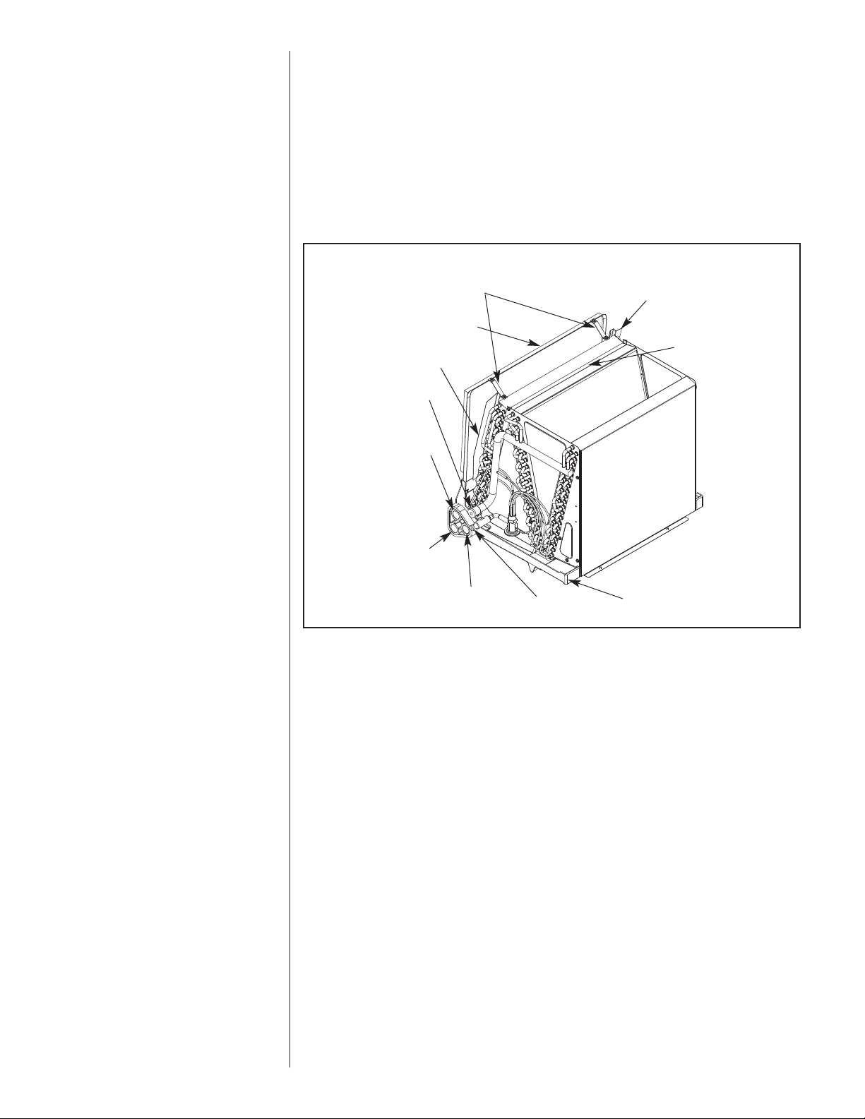
FIGURE 7
INDOOR COIL AND DRAIN PAN SET-UP
STRAPS
HORIZONTAL ADAPTER
FRONT WATER
CATCHER
VAPOR LINE
CONNECTION
AUXILIARY
HORIZONTAL
DRAIN
CONNECTION
PRIMARY
DRAIN
CONNECTION
UPFLOW/DOWNFLOW
DRAIN CONNECTION
KIT
AUXILIARY
LIQUID LINE
CONNECTION
REAR WATER CATCHER
TOP AIR STOP
VERTICAL
DRAIN PAN
A-1037-01
IMPORTANT: Units cannot be installed horizontally laying on or suspended from the
back of the unit.
3.4 INSTALLATION IN AN UNCONDITIONED SPACE
The exterior cabinet of an air handler has a greater risk of sweating when installed in an
unconditioned space than when it is installed in the conditioned space. This is primarily
due to the temperature of the conditioned air moving through the air handler and the air
circulating around the unit where it is installed. For this reason, we recommend the following for all air handler applications, but special attention should be paid to those
installed in unconditioned spaces:
• Duct sizing and airflow are critical and based on the equipment selected
• Supply and return duct attachment: If other than the factory flanges are used, the
attachment of ducting must be insulated and tight to prevent sweating.
• No perimeter supply flanges are provided. If a full perimeter supply duct is used, it is
the responsibility of the installer to provide duct flanges as needed, to secure and seal
the supply duct to prevent air leakage and the sweating that will result.
• All wire penetrations should be sealed. Take care not to damage, remove or compress insulation in those cases.
• In some cases, the entire air handler can be wrapped with insulation. This can be
done as long as the unit is completely enclosed in insulation, sealed and service
access is provided to prevent accumulation of moisture inside the insulation.
• As required, use a secondary pan that will protect the structure from excessive sweating or a restricted coil drain line.
• If a heater kit is installed, be sure the breaker or disconnect cover is sealed tightly to
the door panel.
12
Page 13

4.0 ELECTRICAL WIRING
!
WARNING
Disconnect all power to unit before installing or servicing. More than one disconnect switch may be required to de-energize the equipment. Hazardous voltage can cause severe personal injury or death.
Field wiring must comply with the National Electric Code (C.E.C. in Canada) and any
applicable local ordinance.
4.1 POWER WIRING
It is important that proper electrical power is available for connection to the unit model
being installed. See the unit nameplate, wiring diagram and electrical data in the installation instructions.
• If required, install a branch circuit disconnect of adequate size, located within sight of,
and readily accessible to the unit.
• IMPORTANT: After the Electric Heater is installed, units may be equipped with one,
two, or three 60 amp. circuit breakers. These breaker(s) protect the internal wiring in
the event of a short circuit and serve as a disconnect. Circuit breakers installed within
the unit do not provide over-current protection of the supply wiring and therefore may
be sized larger than the branch circuit protection.
• Supply circuit power wiring must be 75°C minimum copper conductors only. See
Electrical Data in this section for ampacity, wire size and circuit protector requirement.
Supply circuit protective devices may be either fuses or “HACR” type circuit breakers.
7
• Power wiring may be connected to either the right, left side or top. Three
31
/32” dia. concentric knockouts are provided for connection of power wiring to unit.
1
• Power wiring is connected to the power terminal block(s) in unit control compartment.
/8”, 13/32”,
4.2 GROUNDING
!
WARNING
The unit must be permanently grounded. Failure to do so can result in electrical shock causing personal injury or death.
• Grounding may be accomplished by grounding metal conduit when installed in accordance with electrical codes to the unit cabinet.
• Grounding may also be accomplished by attaching ground wire(s) to ground lug(s)
provided in the unit wiring compartment.
• Ground lug(s) are located close to wire entrance on left side of unit (upflow). Lug(s)
may be moved to marked locations near wire entrance on right side of unit (upflow), if
alternate location is more convenient.
• Use of multiple supply circuits require grounding of each circuit to lug(s) provided in
unit.
IMPORTANT: Not all heater kits are supplied with a means of electrical disconnect. If
circuit breakers are supplied with a heater kit, the circuit breakers are NOT rated for circuit protection.
4.3 COPPER WIRE SIZE - AWG. (3% VOLTAGE DROP)
S
L
U
P
P
L
Y
W
I
R
E
200 [61]
E
150 [46]
N
100 [30]
G
50 [15]
T
H
F
E
E
T
12
12
14
14
15
10
10
12
12
20
8
8
8
6
10
10
10
10
25
8
10
8
10
8
30
35
NOTE: WIRE BASED ON COPPER CONDUCTORS 75°C MINIMUM RATING.
FOR MORE THAN 3 CONDUCTORS IN A RACEWAY OR CABLE, SEE
N.E.C. FOR DERATING THE AMPACITY OF EACH CONDUCTOR.
6
8
6
8
8
8
8
40
45
SUPPLY CIRCUIT AMPACITY
50
6
4
4
3
3
2
2
1
0
6
6
4
4
3
3
2
6
6
4
4
3
6
6
4
70
4
80
60
90
3
3
3
100
2
2
110
1
1
1
125
0
0
0
150
00
00
00
00
175
4.4 BLOWER MOTOR ELECTRICAL DATA
RHPL-HM HP Voltage Phase Hertz RPM
2421 1/3 208/230 1 60 300-1100 1.7 4.0 15
3621 1/2 208/230 1 60 300-1100 3.4 6.0 15
4824 3/4 208/230 1 60 300-1100 4.9 9.0 15
6024 3/4 208/230 1 60 300-1100 4.9 9.0 15
Circuit
AMPS
Minimum
Circuit
Ampacity
Max. Circuit
Protector
13
Page 14

4.5 ELECTRIC HEAT ELECTRICAL DATA
Installation of the UL Listed original equipment manufacturer provided heater kits listed in the table below is
recommended for all auxiliary heating requirements.
RHPL-HM
2421 RXBH - 1724?07J Single 208/240 1/60 5.4/7.2 26.0/30.0 1.7 35/40 35/40
3621 Single 208/240 1/60 10.8/14.4 51.9/60.0 3.4 70/80 70/80
4824 RXBH - 1724A18J MULTI. CKT 1 208/240 1/60 6.4/8.5 30.8/35.4 4.9 45/60 45/51
6024 RXBH- 24A20J MULTI. CKT 1 208/240 1/60 7.2/9.6 34.6/40.0 4.9 50/60 50/57
Manufacturer
Model Number
RXBH - 1724?05J Single 208/240 1/60 3.6/4.8 17.3/20.0 1.7 25/30 24/28
RXBH - 1724?10J Single 208/240 1/60 7.2/9.6 34.6/40.0 1.7 50/60 46/53
RXBH - 1724?05J Single 208/240 1/60 3.6/4.8 17.3/20.0 3.4 30/30 26/30
RXBH - 1724?07J Single 208/240 1/60 5.4/7.2 26.0/30.0 3.4 40/45 37/42
RXBH - 1724?10J Single 208/240 1/60 7.2/9.6 34.6/40.0 3.4 50/60 48/55
RXBH - 1724A15J MULTI. CKT 1 208/240 1/60 3.6/4.8 17.3/20.0 3.4 30/30 26/30
RXBH - 1724A18J MULTI. CKT 1 208/240 1/60 6.4/8.5 30.8/35.4 3.4 45/50 43/49
RXBH - 1724?05J Single 208/240 1/60 3.6/4.8 17.3/20.0 4.9 30/35 28/32
RXBH - 1724?07J Single 208/240 1/60 5.4/7.2 26.0/30.0 4.9 40/45 39/44
RXBH - 1724?10J Single 208/240 1/60 7.2/9.6 34.6/40.0 4.9 50/60 50/57
RXBH - 1724A15J MULTI. CKT 1 208/240 1/60 3.6/4.8 17.3/20.0 4.9 30/35 28/32
RXBH - 24A20J MULTI. CKT 1 208/240 1/60 7.2/9.6 34.6/40.0 4.9 50/60 50/57
RXBH - 24A25J MULTI. CKT 1 208/240 1/60 6.0/8.0 29.0/33.3 4.9 45/50 43/48
(4-ton only) MULTI. CKT 2 208/240 1/60 6.0/8.0 29.0/33.3 0 40/45 37/42
RXBH - 1724?07J Single 208/240 1/60 5.4/7.3 26.0/30.0 4.9 40/45 39/44
RXBH - 1724?10J Single 208/240 1/60 5.4/7.2 26.0/30.0 4.9 40/45 39/44
RXBH - 1724A15J MULTI. CKT 1 208/240 1/60 3.6/4.8 17.3/20.0 4.9 30/35 28/32
RXBH - 1724A18J MULTI. CKT 1 208/240 1/60 6.4/8.5 30.8/35.4 4.9 45/60 45/51
RXBH - 24A25J
RXBH-24A30J Single 208/240 1/60 21.6/28.8 103.8/120. 4.9 136/156 150/175
RXBH-24A30J MULTI. CKT 2 208/240 1/60 2-4.8 34.6/40.0 0 44/50 45/50
Type Supply
Circuit
MULTI. CKT 2 208/240 1/60 7.2/9.6 34.6/40.0 0.0 45/50 44/50
Single 208/240 1/60 12.8/17 61.6/70.8 3.4 90/100 82/93
MULTI. CKT 2 208/240 1/60 6.4/8.5 30.8/35.4 0.0 40/45 39/45
Single 208/240 1/60 10.8/14.4 51.9/60.0 4.9 80/90 72/82
MULTI. CKT 2 208/240 1/60 7.2/9.6 34.6/40.0 0 45/50 44/50
Single 208/240 1/60 12.8/17 61.6/70.8 4.9 90/100 84/95
MULTI. CKT 2 208/240 1/60 6.4/8.5 30.8/35.4 0 40/45 39/45
Single 208/240 1/60 14.4/19.2 69.2/80.0 4.9 100/110 93/107
MULTI. CKT 2 208/240 1/60 7.2/9.6 34.6/40.0 0 45/50 44/50
Single 208/240 1/60 18.0/24.0 87.0/99.9 4.9 125/150 115/132
MULTI. CKT 3 208/240 1/60 6.0/8.0 29.0/33.3 0 40/45 37/42
Single 208/240 1/60 10.8/14.4 51.9/60.0 4.9 80/90 72/82
MULTI. CKT 2 208/240 1/60 7.2/9.6 34.6/40.0 0 45/50 44/50
Single 208/240 1/60 12.8/17 61.6/70.8 4.9 90/100 84/95
MULTI. CKT 2 208/240 1/60 6.4/8.5 30.8/35.4 0 40/45 39/45
Single 208/240 1/60 14.4/19.2 69.2/80.0 4.9 100/110 93/107
MULTI. CKT 2 208/240 1/60 7.2/9.6 34.6/40.0 0 45/50 44/50
Single 208/240 1/60 18.0/24.0 87.0/99.9 4.9 125/150 115/132
MULTI. CKT 1 208/240 1/60 6.0/8.0 29.0/33.3 4.9 45/50 43/48
MULTI. CKT 2 208/240 1/60 6.0/8.0 29.0/33.3 0 40/45 37/42
MULTI. CKT 3 208/240 1/60 6.0/8.0 29.0/33.3 0 40/45 37/42
MULTI. CKT 1 208/240 1/60 7.2/9.6 34.6/40.0 4.9 49/56 50/60
MULTI. CKT 3 208/240 1/60 7.2/9.6 34.6/40.0 0 44/50 45/50
Voltage PH/HZ
HeaterkWHeater
AMPS
Motor
Ampacity
Maximum
Circuit
Protection
Minimum
Ampacity
Circuit
NOTES:
• Supply circuit protective devices may be fuses or “HACR” type circuit breakers.
• Largest motor load is included in single circuit and multiple circuit 1.
• If non-standard fuse size is specified, use next size larger fuse size.
• J Voltage (230V) signal phase air handler is designed to be used with single or three phase 230 volt electric heaters. In the case of connecting
3-phase power to the air handler terminal block without the heater, bring only two leads to the terminal block. Cap, insulate and fully secure the
third lead.
• ?Heater kit type A=Breaker B=Terminal Block C=Pullout Disconnect
14
Page 15

5.0 AIR HANDLER Comfort Control2System™
INTERFACE BOARD
FIGURE 8
THE AIR HANDLER CONTROL BOARD EQUIPPED WITH THE Comfort Control2System™
Comfort Control
2
System™ CONTROL WIRING
The RHPL-series of air handlers are designed to operate with conventional 24VAC controls or with a serial communicating system.
2
For the Comfort Control
• An air handler equipped with the Comfort Control2System™
• A condensing unit or heat pump equipped with Comfort Control
• A Comfort Control
If your equipment does not meet this criteria, you must wire it using conventional 24VAC
thermostat control wiring. Reference Section 5.11.
System™, you must have:
2
thermostat
2
System™
5.1 Comfort Control2CONTROL WIRING
The Comfort Control2requires four (4) control wires for unit operation:
R – 24VAC
C – 24VAC common
1 – Data wire 1
2 – Data wire 2
Wiring sizing for Comfort Control2is identical to systems using low voltage 24V wires.
NNoottee::
Comfor
t Control2requires a minimum 18 AWG.
2
IMPORTANT: When using Comfort Control
24VAC thermostat wires. If any connections are made to the G, W1, W2, Y1, Y2, B, or
ODD wires, the Comfort Control
ditional thermostat and will IGNORE ANY COMMUNICATIONS USING DATA WIRE 1
AND DATA WIRE 2.
IMPORTANT: Class 2 low voltage control wire should not be run in conduit with power
wiring and must be separated from power wiring, unless Class 1 wire of proper voltage
rating is used.
• The four 18AWG low voltage control wires must be installed from the thermostat to the
indoor unit and from indoor unit to the outdoor unit. The wire length between the thermostat and indoor unit should not be greater than 100 feet. The wire length between
the indoor unit and outdoor unit should not be greater than 125 feet.
• Low voltage control connections are made by extending wires from top of air handler
using wire nuts.
• See wiring diagrams attached to indoor and outdoor sections to be connected.
2
control will assume the control is being used with a tra-
, do not make any connections to the
15
Page 16

Indoor Unit
1
2
C
R
WIRING INFORMATION
Line Voltage
–Field Installed - - - - - –Factory Standard
1
2
R
C
1
2
R
C
Communicating Thermostat
Outdoor Unit
System™ CONTROL WIRING
2
Comfort Control
• Do not leave excess field control wiring inside unit, pull excess control wire to outside
of unit and provide strain relief for field wiring on inside of cabinet at point wiring penetrates cabinet.
• Make sure, after installation, separation of control wiring and power wiring has been
maintained.
FIGURE 9
TYPICAL The Comfort Control2System™ WIRING DIAGRAM
5.2 Comfort Control2System™ CONTROL BOARD
The RHPL series air handler control, Figure 8, has the following features:
• Memory Card – The memory card stores all information needed for unit operation.
Once the system is wired for serial communications, this information is shared with the
thermostat and outdoor unit. This shared data is available if one of the components in
the system needs to be replaced.
• An automotive-style ATC blade fuse for transformer protection (3 amp).
• An on-board LED to indicate blower CFM.
• An RJ-11 port for use with a diagnostic tool.
• Inputs for field installed supply and return air temperature sensors (available in kit
RXHT-A01)
• DIP switches for airflow adjustments
IMPORTANT: The DIP switches are NOT used when the air handler is wired for serial
communications. Airflow adjustments are performed via the thermostat or a diagnostic
tool.
Installation Verification
• Term and bias dip switches should be on.
• 24V AC power on R&C must be present at the control for the air handler to operate,
reference Figure 9.
• Line voltage must be present at the control for indoor blower operation.
• The RX Data LED will flash green in normal operation. A flashing green light indicates
24VAC is present and the data wires 1 and 2 are wired properly.
IMPORTANT: Diagnostic port is for the diagnostic tool only. Do not attempt to connect
components using a telephone cord. Damage will occur.
IMPORTANT: Diagnostic port is not a phone jack. Connecting to a telephone or telephone system will result in damage.
16
5.3 USING THE ON-BOARD LED TO DETERMINE BLOWER CFM
The CFM LED indicates blower output by flashing one (1) flash for every 100 CFM of
airflow. The LED will pause 1/10 second between each flash.
5.4 AIRFLOW ADJUSTMENTS WITH THE Comfort Control2System™
The RHPL air handler Comfort Control2System™ may operate using the Comfort
2
Control
Comfort Control
2
Control
or via traditional thermostat wiring. When the air handler is wired for the
control have NO affect on the airflow.
2
using Data wire 1 and Data wire 2, the DIP switches on the Comfort
Page 17

2
Airflow (cfm)
Tonnage of heat
pump
2nd Stage 1st Stage
(-)PRL-024JEC 775 625
(-)PRL-036JEC 1200 875
(-)PRL-048JEC 1625 1200
(-)PRL-060JEC 1675 1375
Selection
None
+10%
-10%
Table X.X – Airflow Adjustment Selection Table.
Selection
None
+10%
-10%
Selection
None
+10%
-10%
Table X.X – Airflow Adjustment Selection Table.
Selection
None
+10%
-10%
IMPORTANT: When using the Comfort Control
airflow or on air handler performance.
, the DIP switches have no affect on
5.5 COOLING AIRFLOW SETTINGS (BY TONNAGE)
The RHPL-series of air handlers automatically set cooling airflow when using the
Comfort Control
unit/heat pump and sets airflow for optimum performance and comfort. Refer to Table 2
for the airflow provided when the RHPL air handler is matched to the (-)PRL heat pump.
TABLE 1
RHPL AIRFLOW WHEN MATCHED TO THE (-)PRL HEAT PUMP
2
System™. The air handler detects the tonnage of the condensing
5.6 COOLING AIRFLOW ADJUSTMENT
The Comfort Control2System™ control board does allow the installer to tweak the cooling airflow +/-10% to suit the installation. When using the Comfort Control
the airflow can only be adjusted using the serial communicating thermostat or a service
tool. To adjust the airflow, go to the airflow adjustment menu and select the desired
adjustment. (Reference Table 2.)
TABLE 2
AIRFLOW ADJUSTMENT SELECTION TABLE
2
System™,
Comfort Control
2
System™ CONTROL WIRING
IMPORTANT: Cooling airflow adjustment is accessible via the Comfort Control
mostat or via a service tool. Refer to their instructions to access the cooling airflow
adjustment menu.
NOTE: Cooling airflow adjustments are in effect for cooling operation only. They are
ignored when in heating mode or when electric heat is activated.
5.7 HEATING AIRFLOW ADJUSTMENT
The Comfort Control2control does allow the installer to tweak the heating airflow +/-10%
to suit the installation. When using Comfort Control
adjusted using the Comfort Control
go to the airflow adjustment menu and select the desired adjustment. (Reference Table 3.)
TABLE 3
AIRFLOW ADJUSTMENT SELECTION TABLE
IMPORTANT: Heating airflow adjustment is accessible via the Comfort Control
mostat or via a service tool. Refer to their instructions to access the heating airflow
adjustment menu.
NOTE: Heating airflow adjustments are in effect for heat pump operation only. They
are ignored when in cooling mode or when electric heat is activated.
2
ther-
2
2
thermostat or a service tool. To adjust the airflow,
System™, the airflow can only be
2
ther-
17
Page 18

5.8 ELECTRIC HEAT AIRFLOW
The RHPL-series of air handlers are factory programmed to provide adequate airflow for
the maximum electric heat (auxiliary heat) allowed for a given model. Airflow adjustment
for lower KW heater applications is accessible via the Comfort Control2System thermostat or via a service tool. Refer to their instructions to access the “Heating Airflow
Adjustment” menu.
TABLE 5
ODD TERMINAL
INDOOR INPUT TO “ODD”
AMBIENT TERMINAL
CONDITION (FROM HUMIDISTAT)
HIGH HUMIDITY Ø VAC
LOW HUMIDITY 24 VAC
System™ CONTROL WIRING
2
TABLE 4
ELECTRIC HEAT AIRFLOW FOR THE RHPL- AIR HANDLERS
Air Handler
Model
RHPL-HM2421JC 800 CFM 600 CFM
RHPL-HM3621JC 1200 CFM 600 CFM
RHPL-HM4824JC 1600 CFM 800 CFM
RHPL-HM6024JC 1800 CFM 800 CFM
Above
15KW:
15KW and
below:
5.9 COOLING MODE DEHUMIDIFICATION
The serial communicating control is shipped with “On Demand Dehumidification”(ODD)
turned OFF. On Demand Dehumidification may be activated from the serial communicating
thermostat when the serial communicating thermostat has an on-board humidity sensor.
IMPORTANT: On Demand Dehumidification is accessible via the serial communicating
thermostat or via a service tool. Refer to their instructions to access the ODD airflow
adjustment menu.
5.10 COOLING DELAY PROFILES
The RHPL air handler is factory configured with optimum ON/OFF delays to maximize
energy efficiency and comfort. In certain situations, the installer may choose an alternate
profile to tweak the system operation for the building load and to maximize comfort. The
alternate profiles are defined below:
IMPORTANT: On Demand Dehumidification, ODD, is the preferred method to maximize
comfort with little or no loss of energy efficiency. If using ODD, do NOT use any of the
alternate profiles. Only use the factory default profile. Use of the alternate profiles with
ODD will decrease energy efficiency with no gain in comfort.
Profile A – Factory default profile.
On Delay
Air Handler
RHPL-HM2421 No Delay N/A 45
RHPL-HM3621 No Delay N/A 45
RHPL-HM4824 No Delay N/A 45
RHPL-HM6024 No Delay N/A 45
Delay Duration
(second)
% Rated Airflow Off Delay (seconds)
Comfort Control
Profile B – Quiet Start profile
The Quiet Start profile is configured to bring the blower up to 50% airflow for 30 seconds
before advancing to 100% airflow. This helps to minimize the blower noise at system
startup.
On Delay
Air Handler
RHPL-HM2421 30 50 15
RHPL-HM3621 30 50 15
RHPL-HM4824 30 50 15
RHPL-HM6024 30 50 15
Delay Duration
(second)
% Rated Airflow Off Delay (seconds)
Profile C – Humid profile
The humid profile is configured to run the blower at 80% airflow for about the first four
minutes of system operation to remove more moisture from the conditioned space.
On Delay
Air Handler
RHPL-HM2421 255 80 0
RHPL-HM3621 255 80 0
RHPL-HM4824 255 80 0
RHPL-HM6024 255 80 0
Delay Duration
(second)
% Rated Airflow Off Delay (seconds)
18
Page 19

B
W2
W1
B
C
G
(-)HPL Air
Handler
Y1
E/W1
Typical Two-Stage Thermostat
(-)PRL
Heat Pump
Outdoor
Unit
Y2
C
R
B
Y2
Field Installed
Line Voltage
-
WIRING INFORMATION
Factory Standard
-
ODD
R
Y1
Y2
G
W2
R
Y1
C
L
D
Y
Y/BL
BL
R
BR
W/R
PR
*
B
W2
W1
B
C
G
(-)HPL Air
Handler
Y1
E/W1
Typical Two-Stage Thermostat
(-)PRL
Heat Pump
Outdoor
Unit
Y2
C
R
B
Y2
Field Installed
Line Voltage
-
WIRING INFORMATION
Factory Standard
-
ODD
R
Y1
Y2
G
W2
R
Y1
C
L
D
Y
Y/BL
BL
R
BR
W/R
PR
Humidistat
*
B
W2
W1
B
C
G
(-)HPL Air
Handler
Y1
E/W1
Typical Two-Stage Thermostat
(-)PRL
Heat Pump
Outdoor
Unit
Y2
C
R
B
Y2
Field Installed
Line Voltage
-
WIRING INFORMATION
Factory Standard
-
ODD
R
Y1
Y2
G
W2
R
Y1
C
L
D
Y
Y/BL
BL
R
BR
W/R
PR
DHM
*
B
W2
W1
B
C
G
(-)HPL Air
Handler
Y1
E/W1
Typical Two-Stage Thermostat
(-)PRL
Heat Pump
Outdoor
Unit
Y2
C
R
B
Y2
Field Installed
Line Voltage
-
WIRING INFORMATION
Factory Standard
-
ODD
R
Y1
Y2
G
W2
R
Y1
C
L
D
Y
Y/BL
BL
R
BR
W/R
PR
DHM
L
*
WIRE COLOR CODE
BK – BLACK G – GREEN PR – PURPLE Y – YELLOW
BR – BROWN GY – GRAY R – RED
BL – BLUE O – ORANGE W – WHITE
FIGURE 10
TYPICAL 2-STAGE THERMOSTAT: (-)PRL HEAT PUMP WITH
ELECTRIC HEAT
*
When using
DIP SWITCH POSITIONS
ON
OFF
S1
S2
S3
S4
S5
S6
S7
13kW and higher
it is recommitted
to jump W1 and W2
together for
maximum
temperature rise.
S8
FIGURE 11
TYPICAL TWO-STAGE THERMOSTAT: (-)PRL HEAT PUMP WITH
ELECTRIC HEAT USING A HUMIDISTAT FOR DEHUMIDIFICATION*.
*See Section 5.17 for proper DIP switch selection.
DIP SWITCH POSITIONS
ON
OFF
S1
S2
S3
S4
S5
S6
S7
*
When using
13kW and higher
it is recommitted
to jump W1 and W2
together for
maximum
temperature rise.
S8
CONVENTIONAL THERMOSTAT WIRING
FIGURE 12
TYPICAL TWO-STAGE THERMOSTAT: (-)PRL HEAT PUMP WITH
ELECTRIC HEAT USING A TWO-STAGE THERMOSTAT WITH
DEHUMIDIFICATION*
DIP SWITCH POSITIONS
ON
OFF
S1
S2
S3
S4
*See Section 5.17 for proper DIP switch selection.
S5
S6
S8
S7
*
When using
13kW and higher
it is recommitted
to jump W1 and W2
together for
maximum
temperature rise.
FIGURE 13
(-)PRL HEAT PUMP WITH ELECTRIC HEAT USING A TWO-STAGE
THERMOSTAT WITH DEHUMIDIFICATION* AND A MALFUNCTION
LIGHT
*See Section 5.17 for proper DIP switch selection.
DIP SWITCH POSITIONS
ON
OFF
S1
S2
S3
S4
S5
S6
S7
*
When using
13kW and higher
it is recommitted
to jump W1 and W2
together for
maximum
temperature rise.
S8
19
Page 20

W2
C
R
(-)HPL Air
Handler
Single-Stage A/C Thermostat
C
-Field Installed
Line Voltage
WIRING INFORMATION
-Factory Standard
ODD
B
Y1
G
R
Y
C
W1
G
Y2
W
Y
W/BL
G/BK
Y
W/BK
BL
G/Y
BR
R
Y/BL
G
W2
C
R
(-)HPL Air
Handler
Single-Stage A/C Thermostat
A/C Outdoor Unit
C
Y
Field Installed
Line Voltage
-
WIRING INFORMATION
Factory Standard
-
ODD
B
Y1
W
Y
R
C
Y
W/BL
Humidistat
G
W1
Y2
G/BK
W/BK
BL
G/Y
BR
R
Y/BL
G
W2
C
R
(-)HPL Air
Handler
Single-Stage A/C Thermostat
A/C Outdoor Unit
C
Y
Field Installed
Line Voltage
-
WIRING INFORMATION
Factory Standard
-
ODD
B
Y1
W
Y
R
C
Y
W/BL
G
W1
Y2
G/BK
W/BK
BL
G/Y
BR
R
Y/BL
G
W2
C
R
(-)HPL Air
Handler
Single-Stage A/C Thermostat
A/C Outdoor Unit
C
Y
Field Installed
Line Voltage
-
WIRING INFORMATION
Factory Standard
-
ODD
B
Y1
W
Y
R
C
Y
W/BL
Humidistat
G
W1
Y2
G/BK
W/BK
BL
G/Y
BR
R
Y/BL
WIRE COLOR CODE
BK – BLACK G – GREEN PR – PURPLE Y – YELLOW
BR – BROWN GY – GRAY R – RED
BL – BLUE O – ORANGE W – WHITE
FIGURE 14
TYPICAL SINGLE-STAGE THERMOSTAT: SINGLE STAGE STRAIGHT
COOLING WITH ELECTRIC HEAT
Y1 ASC FLOW
FIGURE 15
TYPICAL SINGLE-STAGE THERMOSTAT: SINGLE STAGE STRAIGHT
COOLING WITH ELECTRIC HEAT AND USING A HUMIDISTAT FOR
DEHUMIDIFICATION
Y1 AIR FLOW
FIGURE 16
TYPICAL SINGLE-STAGE THERMOSTAT: SINGLE STAGE STRAIGHT
COOLING WITH ELECTRIC HEAT
Y2 AIR FLOW
CONVENTIONAL THERMOSTAT WIRING
20
FIGURE 17
TYPICAL SINGLE-STAGE THERMOSTAT: SINGLE STAGE
STRAIGHT COOLING WITH ELECTRIC HEAT AND USING A
HUMIDISTAT FOR DEHUMIDIFICATION
Y2 AIR FLOW
Page 21

Profile D – Dry Climate profile
The Dry Climate profile is configured for areas that require little to no additional dehumidification.
On Delay
Air Handler
RHPL-HM2421 150 88 60
RHPL-HM3621 150 88 60
RHPL-HM4824 150 88 60
RHPL-HM6024 150 88 60
Delay Duration
(second)
% Rated Airflow Off Delay (seconds)
5.11 CONVENTIONAL 24VAC THERMOSTAT CONTROL WIRING
The (-)PRL series of heat pumps allow the installer to use conventional 24VAC control
wiring and a conventional thermostat for proper unit operation.
IMPORTANT: The preferred method of unit installation and operation is by the Comfort
2
Control
tic information is not available when the (-)PRL unit is using a conventional thermostat.
Reference section 5.1 Comfort Control2System™ Control Wiring.
Thermostat control wiring requires a minimum of eight (8) wires for proper unit operation:
Optional wiring:
NOTE: W1 and W2 may be jumpered together to energize all the electric heat when a
call for electric heat is received if warmer supply air temperature is desired.
NOTE: When using 24VAC thermostat control wiring, the serial communicating control
will ignore any inputs to Data wire 1 and Data wire 2.
IMPORTANT: Class 2 low voltage control wire should not be run in conduit with power
wiring and must be separated from power wiring, unless Class 1 wire of proper voltage
rating is used.
Low voltage control wiring should be 18 AWG color-coded (105°C minimum). For
lengths longer than 100 ft., 16 AWG wire should be used.
Low voltage control connections are made by extending wires from top of air handler
using wire nuts.
See wiring diagrams attached to indoor and outdoor sections to be connected
Do not leave excess field control wiring inside unit, pull excess control wire to outside of
unit and provide strain relief for field wiring on inside of cabinet at point wiring penetrates
cabinet.
Make sure, after installation, separation of control wiring and power wiring has been
maintained.
System™, which allows access to the fault history of the system. This diagnos-
R – 24VAC
C – 24VAC common
G – Constant Fan
W1 – First stage electric heat
W2 – Second stage electric heat
Y1 – First stage operation
Y2 – Second stage operation
B – Heat pump operation
ODD – On demand humidification
CONVENTIONAL THERMOSTAT WIRING
5.12 USING THE ON-BOARD LED TO DETERMINE BLOWER CFM
The CFM LED indicates blower output by flashing one (1) flash for every 100 CFM of airflow. The LED will pause 1/10 second between each flash.
5.13 COOLING AIRFLOW SETTINGS
FIGURE 18
DIP SWITCH SETTING FOR COOLING AIRFLOW
21
Page 22

The RHPL-series of air handlers are factory configured to for proper airflow. The cooling
Cooling Airflow
2-ton 3-ton 4-ton 5-ton
Y1 Y2 Y1 Y2 Y1 Y2 Y1 Y2
CFM
625 775 900 1200 1200 1625 1375 1675
Table X.X – Airflow settings when using traditional 24VAC thermostat
airflow (CAF) is fixed and the DIP switch settings have no effect on airflow. The factory
setting is:
TABLE 6
AIRFLOW SETTINGS WHEN USING TRADITIONAL 24VAC THERMOSTAT
Cooling Airflow (also see Section 5.14)*
RHPL-HM2421 RHPL-HM3621 RHPL-HM4824 RHPL-HM6024
CFM
Y1
625 775 900 1200 1200 1625 1375 1675
Y2 Y1 Y2 Y1 Y2 Y1 Y2
IMPORTANT: The DIP switches are active only when using conventional a 24VAC thermostat. If using the Comfort Control
flows.
FIGURE 19
DIP SWITCH SETTING FOR HEAT PUMP AIRFLOW
2
System™, refer to Section 5.13 for adjusting air-
*5.14 COOLING AIRFLOW ADJUSTMENTS WITH SINGLE STAGE
CONDENSING UNITS
The (-)HPL- series of air handlers can be used with select single-stage condensing
units. Refer to the Engineering Specifications Sheets to determine the required airflow
for your particular combination. Refer to Table 6 to determine the air-flows available for
each (-)HPL- air handler. Reference Figures 14-17 for proper wiring of the system.
5.15 HEATING AIRFLOW ADJUSTMENT
The RHPL-series of air handlers are factory configured to for proper airflow. The heat
CONVENTIONAL THERMOSTAT WIRING
pump airflow (PAF) is fixed and the DIP switch settings have no effect on airflow. The
factory setting is:
TABLE 7
AIRFLOW SETTINGS WHEN USING TRADITIONAL 24VAC THERMOSTAT
RHPL-HM2421 RHPL-HM3621 RHPL-HM4824 RHPL-HM6024
Y1
CFM
IMPORTANT: The DIP switches are active only when using conventional a 24VAC thermostat. If using the Comfort Control
flows.
625 775 900 1200 1200 1625 1375 1675
Y2 Y1 Y2 Y1 Y2 Y1 Y2
Heating Airflow
2
System™, refer to Section 5.14 for adjusting air-
22
Page 23

FIGURE 20
DIP SWITCH SETTING FOR AIRFLOW ADJUSTMENTS
5.16 AIRFLOW ADJUSTMENT (TRIM)
Cooling and heat pump airflow can be adjusted +/-10% to suit the installation. To adjust
the airflow, set DIP switches 5 & 6 per Table 8:
TABLE 8
AIRFLOW ADJUSTMENT SELECTION TABLE
CONVENTIONAL THERMOSTAT WIRING
DIP Switch Settings
RHPL-HM2421
Airflow Adjustments
RHPL-HM3621
RHPL-HM4824
RHPL-HM6024
Position Switch5Switch6Y1 Y2 Y1 Y2 Y1 Y2 Y1 Y2
A OFF OFF 625 775 900 1200 1200 1625 1375 1675
B ON OFF 700 850 1000 1325 1325 1800 1525 1850
C OFF ON 575 700 800 1075 1075 1475 1250 1500
D ON ON 625 775 900 1200 1200 1625 1375 1675
IMPORTANT: The DIP switches are active only when using conventional a 24VAC thermostat. If using the Comfort Control
2
System™, refer to Section 5.15 for adjusting air-
flows.
NOTE: Airflow adjustment is active for cooling and heat pump operation only. They are
ignored when electric heat is activated.
5.17 ELECTRIC HEAT AIRFLOW
The RHPL-series of air handlers are shipped with the “Low KW airflow” feature turned
OFF. Activate lower airflow feature for lower KW electric heater applications by turning DIP
switch 8 ON.
IMPORTANT: The DIP switches are active only when using a conventional 24VAC thermostat. If using the Comfort Control
flow adjustment.
ELECTRIC HEAT AIRFLOW FOR THE RHPN AIR HANDLERS
Air Handler
Model
RHPL-HM2421JC 800 CFM 600 CFM
RHPL-HM3621JC 1200 CFM 600 CFM
RHPL-HM4824JC 1600 CFM 800 CFM
RHPL-HM6024JC 1800 CFM 800 CFM
Above
15KW:
2
System™, refer to section 5.8 for low KW heat air-
15KW and
below:
88
5.18 COOLING MODE DEHUMIDIFICATION
FIGURE 21
ON DEMAND DEHUMIDIFICATION DIP SWITCH
23
Page 24

The RHPL-series air handler is shipped with “On Demand Dehumidification” (ODD)
Figure X – On Demand Dehumidification DIP Switch
Normal Humidity Result
A 24VAC signal is applied to
the ODD terminal
Full rated airflow is delivered
by the blower
High Humidity Result
No signal applied to the ODD
terminal
Airflow is reduced by a preset
amount to increase latent
capacity
Air Handler Cooling Airflow
Reduction
2-ton 85%
3-ton
4-ton
5-ton
80%
Figure X – On Demand Dehumidification DIP Switch
The (-)HPL-series air handler is shipped with “On Demand Dehumidification” (ODD) turned
OFF. On Demand Dehumidification is used in conjunction with a traditional 24VAC thermostat
equipped with an on-board humidity sensor. Activate ODD by turning DIP switch 7 ON. When
ODD is turned ON, the thermostat sends a 24VAC signal to the ODD input of the air handler.
Operation is:
Normal Humidity (humidity BELOW the thermostat set point):
Normal Humidity Result
A 24VAC signal is applied to
the ODD terminal
Full rated airflow is delivered
by the blower
High Humidity (humidity ABOVE the thermostat set point):
High Humidity Result
No signal applied to the ODD
terminal
Airflow is reduced by a preset
amount to increase latent
capacity
turned OFF. On Demand Dehumidification is used in conjunction with a traditional
24VAC thermostat equipped with an on-board humidity sensor. Activate ODD by turning DIP switch 7 ON. ODD operation is controlled by the indoor humidity sensed at the
thermostat. Operation is:
Normal Humidity (humidity BELOW the thermostat set point):
High Humidity (humidity ABOVE the thermostat set point):
The RHPL air handler is programmed to provide maximum efficiency and optimum
humidity removal. When high humidity is detected, the air handler reduces cooling airflow defined in Table 9.
TABLE 9
ODD AIRFLOW REDUCTION
IMPORTANT: The DIP switches are active only when using conventional a 24VAC ther-
mostat. If using the Comfort Control
(Refer to Section 5.9.)
NNOOTTEE::
airflow adjustments are active for cooling operation only. They are
ODD
ignored when the heat pump is in heating mode or when electric heat is activated.
TABLE 10
SELECTION C EXPLANATION: ON DEMAND DEHUMIDIFICATION
CONVENTIONAL THERMOSTAT WIRING
24
SWITCH 7
POSITION
ON
ODD
INPUT
NONE 500 625 725 950 950 1300 1100 1350
24VAC 625 775 900 1200 1200 1625 1375 1675
5.19 COOLING DELAY PROFILES
Cooling delay profiles are not available when the RHPL air handler is controlled using a
conventional 24VAC thermostat. These profiles are available only when the air handler
is wired for the Comfort Control
Cooling Delay Profiles wiring.
5.20 AIR HANDLER DIAGNOSTIC CODES
Descriptions of the air handler Comfort Control2diagnostic codes are provided below.
These codes can be displayed at the thermostat or via a diagnostic tool.
IMPORTANT: Air handler diagnostic codes are available at the thermostat when the
system is wired for Comfort Control
RHPL-HM2421
Y1
Y2
RHPL-HM3621 RHPL-HM4824 RHPL-HM6024
2
2
System™, refer to Section 5.17 for adjusting airflows.
COOLING AIRFLOW - CFM
Y1 Y1 Y1
Y2 Y2
Y2
System™. Refer to Section 5.10 for Comfort Control
2
.
2
Page 25

AIR HANDLER DIAGNOSTIC CODES
X.X Air Handler Diagnostic Codes
Descriptions of the air handler serial communicating control diagnostic codes are provided
below. These codes can be displayed at the thermostat or via a diagnostic tool.
IMPORTANT: Air handler diagnostic codes are available at the thermostat when the system is
wired for serial communications. If
7-Segment
LEDs Display
Code
Diagnostic Description
Status/Possible Cause – Troubleshooting
Information
d1 – No Shared Data
ELECTRONICS GROUP TO
DESCRIBE
d3 – Airflow CFM Mismatch
The indoor air mover (air handler/furnace)
cannot supply the required airflow for
• Misapplied/wrong indoor air mover – replace
with properly sized air handler/furnace.
X.X Air Handler Diagnostic Codes
Descriptions of the air handler serial communicating control diagnostic codes are provided
below. These codes can be displayed at the thermostat or via a diagnostic tool.
IMPORTANT: Air handler diagnostic codes are available at the thermostat when the system is
wired for serial communications. If
7-Segment
LEDs Display
Code
Diagnostic Description
Status/Possible Cause – Troubleshooting
Information
d1 – No Shared Data
ELECTRONICS GROUP TO
DESCRIBE
d3 – Airflow CFM Mismatch
The indoor air mover (air handler/furnace)
cannot supply the required airflow for
proper system operation
• Misapplied/wrong indoor air mover – replace
with properly sized air handler/furnace.
d4 – (Device) Memory Card Invalid for
Device
•
•
•
X.X Air Handler Diagnostic Codes
Descriptions of the air handler serial communicating control diagnostic codes are provided
below. These codes can be displayed at the thermostat or via a diagnostic tool.
IMPORTANT: Air handler diagnostic codes are available at the thermostat when the system is
wired for serial communications. If
7-Segment
LEDs Display
Code
Diagnostic Description
Status/Possible Cause – Troubleshooting
Information
d1 – No Shared Data
ELECTRONICS GROUP TO
DESCRIBE
d3 – Airflow CFM Mismatch
The indoor air mover (air handler/furnace)
cannot supply the required airflow for
proper system operation
• Misapplied/wrong indoor air mover – replace
with properly sized air handler/furnace.
d4 – (Device) Memory Card Invalid for
Device
•
•
•
7-Segment
LEDs Display
Code
Diagnostic Description
Status/Possible Cause – Troubleshooting
Information
d1 – No Shared Data
The control board does not have shared
data.
• Replace memory card with correct system
information
d3 – Airflow CFM Mismatch
The air handler cannot supply the required
airflow for proper system operation
• Misapplied/wrong indoor air mover – replace
with properly sized air handler/furnace.
d4 – (Device) Memory Card Invalid for
Device
The data in the memory card inserted into
the control board does not match the data in
the control.
• Check memory card to ensure it matches
device
d
5 – Card Hardware Conflict
The motor horsepower is not correct for the
air handler
• Replace the air handler motor with the correct
horsepower motor.
• Replace the memory card with correct system
information.
d8 – Old Shared Data
System data is obsolete
• If system will not operate, order new memory
card to update system information.
68 – ECM No Signal
The ECM motor is not communicating to
the air handler control board.
• Make sure the ECM motor wiring harness
plugged into the ECM motor and control
board.
• Test the ECM motor for proper operation using
a service tool.
81 – Return Air Sensor Out of Range
The resistance of the sensor out of range for
normal operation.
• Make sure the sensor is plugged into the air
handler control board.
• Check the resistance of the sensor. Replace if
7-Segment
LEDs Display
Code
Diagnostic Description
Status/Possible Cause – Troubleshooting
Information
d1 – No Shared Data
The control board does not have shared
data.
• Replace memory card with correct system
information
d3 – Airflow CFM Mismatch
The air handler cannot supply the required
airflow for proper system operation
• Misapplied/wrong indoor air mover – replace
with properly sized air handler/furnace.
d4 – (Device) Memory Card Invalid for
Device
The data in the memory card inserted into
the control board does not match the data in
the control.
• Check memory card to ensure it matches
device
d
5 – Card Hardware Conflict
The motor horsepower is not correct for the
air handler
• Replace the air handler motor with the correct
horsepower motor.
• Replace the memory card with correct system
information.
d8 – Old Shared Data
System data is obsolete
• If system will not operate, order new memory
card to update system information.
68 – ECM No Signal
The ECM motor is not communicating to
the air handler control board.
• Make sure the ECM motor wiring harness
plugged into the ECM motor and control
board.
• Test the ECM motor for proper operation using
a service tool.
81
– Return Air Sensor Out of Range
The resistance of the sensor out of range for
normal operation.
• Make sure the sensor is plugged into the air
handler control board.
• Check the resistance of the sensor. Replace if
it is out of tolerance.
82 – Supply Air Sensor Out of Range
The resistance of the sensor out of range for
normal operation.
• Make sure the sensor is plugged into the air
handler control board.
• Check the resistance of the sensor. Replace if
X.X Air Handler Diagnostic Codes
Descriptions of the air handler serial communicating control diagnostic codes are provided
below. These codes can be displayed at the thermostat or via a diagnostic tool.
IMPORTANT: Air handler diagnostic codes are available at the thermostat when the system is
wired for serial communications. If
7-Segment
LEDs Display
Code
Diagnostic Description
Status/Possible Cause – Troubleshooting
Information
d1 – No Shared Data
ELECTRONICS GROUP TO
DESCRIBE
d3 – Airflow CFM Mismatch
The indoor air mover (air handler/furnace)
cannot supply the required airflow for
proper system operation
• Misapplied/wrong indoor air mover – replace
with properly sized air handler/furnace.
d4 – (Device) Memory Card Invalid for
Device
•
•
•
30
– Fuse Open
The ICC detects the on-board fuse is open
• The 3-amp fuse on the ICC is open.
• Low voltage wiring at R and C is damaged or
miswired.
•
•
7-Segment
LEDs Display
Code
Diagnostic Description
Status/Possible Cause – Troubleshooting
Information
d1 – No Shared Data
ELECTRONICS GROUP TO
DESCRIBE
d3 – Airflow CFM Mismatch
The indoor air mover (air handler/furnace)
cannot supply the required airflow for
proper system operation
• Misapplied/wrong indoor air mover – replace
with properly sized air handler/furnace.
d4 – (Device) Memory Card Invalid for
Device
•
•
•
Descriptions of the ICC diagnostic codes are provided below:
7-Segment
LEDs Display
Code
d1 – No Shared Data
The control board does not have shared data.
d3 – Airflow CFM Mismat ch
The air handler canno t supply th e required
airflow for proper system operation
d4 – (Device) Memory Card Invalid for
Device
The memory card is mis sing or the data in the
memory card does not match the data in th e
control.
d5 – Card Hardware Conflict
The motor horsepower is not correct for the
air handler
d6 – BLWR HP CNFLCT
Blower Horsepower conflict
The horsepo wer data in the memory card
does not match the moto r hors epower.
Diagnostic Description
7
0
d7 – BLWER MFG CNFLCT
The System does no t have any data on the
installed moto r.
d8 – Old Shared Data
System data is obsolete
60 – BLWR FLT–RUN
The ECM motor is running but has a
fault
61 – BLWR FLT–NO RUN
The ECM motor is not operat ing
68 – ECM No Sign al
The ECM motor is not communicat ing to
the air handler contro l board.
81 – Return Air Sensor Out of Range
The resistan ce of the sens or out of range for
normal op eration.
82 – Supply Air Sensor Out of Rang e
The resistan ce of the sens or out of range for
normal op eration.
93 – Internal Con trol Fault
The air handler cont rol is not functionin g.
Status/Possible Cause – Troubleshooting
• Rep lace memory card with correct syst em
information
• Mi sapplied/wrong indoor air mover – replace
with prop erly sized air handler/furnace.
• Ch eck memory card to ensure it match es
device
• Ch eck if memory card is present
• Rep lace the air han dler moto r wit h th e correct
horsepower motor.
• Rep lace the memory card with correct system
information.
• Rep lace the motor with correct horsep ower
motor.
• Rep lace the memory card with correct system
information. Check memory card to ens ure
it matches device
• Rep lace the memory card with correct system
information.
• If sy stem will not operate, order new memory
card to update system info rmation.
• TEST the ECM for prop er operatio n.
• Mak e sure the ECM motor wiring harn ess is
plugged int o th e ECM motor and cont rol board.
• Test the ECM motor for proper operatio n.
• Mak e sure the ECM motor wiring harn ess is
plugged int o th e ECM motor and cont rol
board.
• Test the ECM motor for proper operatio n using
a service tool.
• Mak e sure the senso r is plugged int o the air
handler cont rol board.
• Ch eck the resistan ce of the sens or. Replace if
it is out of to lerance.
• Mak e sure the senso r is plugged int o the air
handler cont rol board.
• Ch eck the resistan ce of the sens or. Replace if
it is out of to lerance.
• Ch eck contro l for proper system operation.
• Rep lace contro l
Information
CONVENTIONAL THERMOSTAT WIRING
25
Page 26

6.0 DUCTWORK
Field ductwork must comply with the National Fire Protection Association NFPA 90A,
NFPA 90B and any applicable local ordinance.
!
WARNING
Do not, under any circumstances, connect return ductwork to any other heat
producing device such as fireplace insert, stove, etc. Unauthorized use of
such devices may result in fire, carbon monoxide poisoning, explosion, personal injury or property damage.
Sheet metal ductwork run in unconditioned spaces must be insulated and covered with
a vapor barrier. Fibrous ductwork may be used if constructed and installed in accordance with SMACNA Construction Standard on Fibrous Glass Ducts. Ductwork must
comply with National Fire Protection Association as tested by U/L Standard 181 for
Class I Air Ducts. Check local codes for requirements on ductwork and insulation.
• Duct system must be designed within the range of external static pressure the unit is
designed to operate against. It is important that the system airflow be adequate.
Make sure supply and return ductwork, grills, special filters, accessories, etc. are
accounted for in total resistance. See airflow performance tables in this manual.
• Design the duct system in accordance with “ACCA” Manual “D” Design for
Residential Winter and Summer Air Conditioning and Equipment Selection. Latest
editions are available from: “ACCA” Air Conditioning Contractors of America, 1513
16th Street, N.W., Washington, D.C. 20036. If duct system incorporates flexible air
duct, be sure pressure drop information (straight length plus all turns) shown in
“ACCA” Manual “D” is accounted for in system.
• Supply plenum is attached to the 3/4” duct flanges supplied on the unit around the
blower outlet. Flanges are flat for shipping purposes and must be bent up along perforated edge around blower opening. Be sure to bend flanges completely up so they
do not interfere with air being discharged from blower.
IMPORTANT: Flanges around blower opening for attaching supply duct must be up out
of blower discharge even if not used so they do not restrict airflow from blower.
IMPORTANT: If an elbow is included in the plenum close to the unit, it must not be
smaller than the dimensions of the supply duct flange on the unit.
• Some units with electric heaters require 1 in. clearance to supply plenum and branch
ducts to combustible material for the first 3 feet from the unit. See CLEARANCES.
• A 3/4” return duct flange is supplied on all sides of the air inlet opening of the unit coil
casing. If the unit is to be installed without a coil casing (no indoor coil), a 3/4”flange
is supplied on the back and sides of the air inlet opening of the blower casing. No
flange is provided on the front of the opening to the blower casing. If return duct is
attached to the inlet of the blower casing, the front flange of the duct should be run up
into the opening or 90° brake made on the front flange to tape to the front of the blower casing.
• IMPORTANT: The front flange on the return duct if connected to the blower casing
must not be screwed into the area where the power wiring is located. Drills or sharp
screw points can damage insulation on wires located inside unit.
• Return duct flanges on blower or coil casing are flat for shipping purposes and must
be bent out along perforated edge around opening.
• Secure the supply and return ductwork to the unit flanges, using proper fasteners for
the type of duct used and tape the duct-to-unit joint as required to prevent air leaks.
26
Page 27

7.0 REFRIGERANT CONNECTIONS
Keep the coil connections sealed until refrigerant connections are to be made. See the
Installation Instructions for the outdoor unit for details on line sizing, tubing installation,
and charging information.
Coil is shipped with a low (5 - 10 PSIG) pressure charge of dry nitrogen. Evacuate the
system before charging with refrigerant.
Install refrigerant tubing so that it does not block service access to the front of the unit.
Nitrogen should flow through the refrigerant lines while brazing.
Use a brazing shield to protect the cabinet’s paint from being damaged by torch flames.
After the refrigerant connections are made, seal the gap around the connections with
pressure sensitive gasket. If necessary, cut the gasket into two pieces for a better seal.
7.1 TEV SENSING BULB
IMPORTANT: DO NOT perform any soldering with the TEV bulb attached to any line.
After soldering operations have been completed, clamp the TEV bulb securely on the
suction line at the 10 to 2 o’clock position with the strap provided in the parts bag.
Insulate the TEV sensing bulb and suction line with the provided pressure sensitive
insulation (size 4” x 7”) and secure with provided wire ties.
IMPORTANT: TEV sensing bulb should be located on a horizontal section of suction
line, just outside of coil box.
7.2 CONDENSATE DRAIN TUBING
Consult local codes or ordinances for specific requirements.
IMPORTANT: When making drain fitting connections to the drain pan, use a thin layer
of Teflon paste, silicone or Teflon tape and install hand tight.
IMPORTANT: When making drain fitting connections to drain pan, do not overtighten.
Overtightening fittings can split pipe connections on the drain pan.
• Install drain lines so they do not block service access to front of the unit. Minimum
clearance of 24 inches is required for filter, coil or blower removal and service access.
• Make sure unit is level or pitched slightly toward primary drain connection so that
water will drain completely from the pan. (See Figure 13.)
• Do not reduce drain line size less than connection size provided on condensate drain
pan.
• All drain lines must be pitched downward away from the unit a minimum of 1/8” per
foot of line to ensure proper drainage.
• Do not connect condensate drain line to a closed or open sewer pipe. Run condensate to an open drain or outdoors.
• The drain line should be insulated where necessary to prevent sweating and damage
due to condensate forming on the outside surface of the line.
• Make provisions for disconnecting and cleaning of the primary drain line should it
become necessary. Install a 3 in. trap in the primary drain line as close to the unit as
possible. Make sure that the top of the trap is below connection to the drain pan to
allow complete drainage of pan (See Figure 21).
27
Page 28

FIGURE 22
CONDENSATE DRAIN TRAP
DO NOT OPERATE UNIT WITHOUT
CONDENSATE DRAIN TRAP.
UNIT
3''
3''
DO NOT OVERTIGHTEN DRAIN FITTING
UNIT MUST BE SLIGHTLY INCLINED
TOWARD DRAIN CONNECTION.
• Auxiliary drain line should be run to a place where it will be noticeable if it becomes
operational. Occupant should be warned that a problem exists if water should begin
running from the auxiliary drain line.
• Plug the unused drain connection with the plugs provided in the parts bag, using a
thin layer of teflon paste, silicone or teflon tape to form a water tight seal.
• Test condensate drain pan and drain line after installation is complete. Pour water
into drain pan, enough to fill drain trap and line. Check to make sure drain pan is
draining completely, no leaks are found in drain line fittings, and water is draining
from the termination of the primary drain line.
7.3 DUCT FLANGES
Field-installed duct flanges (4 pieces) are shipped with units. Install duct flanges as
needed on top of the unit. (See Figure 3.)
8.0 AIR FILTER (Not Factory-Installed)
If a remote filter is installed, it should be sized for a maximum of 300 feet/min. air velocity for the CFM required.
IMPORTANT: Do not operate system without a filter. A filter is required to protect the
coil, blower and internal parts from excessive dirt and dust.
9.0 AIRFLOW PERFORMANCE
Airflow performance data is based on cooling performance with a coil and no filter in
place. Select performance table for appropriate unit size, voltage and number of electric
heaters to be used. Make sure external static applied to unit allows operation within the
minimum and maximum limits shown in table on the next page for both cooling and electric heat operation. For optimum blower performance, operate the unit in the .1 [3 mm] to
1.00 inches [25 mm] W.C. external static range. Units with coils should be applied with a
minimum of .1 inch [3 mm] W.C. external static.
28
Page 29

Size
Motor HP
Thermostat
Input
0.1 0.2 0.3 0.40.50.60.70.8 0.9 1.0
550 575 600 600 625 625625600575550
455 540 620 695 760 8258859409851030
40557085105 120135150170185
775 775 775 800 800 825825825825825
540 615 685 750 810 870 925 975 1020 1065
70 90 115 135 160 180205225250270
875 900 900 900 900 900900900900875
570 645 715 775 835 890 945 990 1030 1070
90 110 135 155 180 200220240265285
1175 1200 1200 1200 122512251200 1200 1200 1200
700 760 820 875 925 9701015 1055 1095 1125
180 205 235 265 290 320345370400425
1200 1175 1175 1200 122512251200 1200 1200 1200
535 595 650 700 750 800840880915950
130 160 190 220 250 280305335365390
1625 1650 1650 1650 167516751675 1650 1650 1625
635 690 745 795 840 8809159509801005
245 295 340 385 425 465500535565590
1375 1375 1375 1375 137513751375 1350 1350 1350
575 630 685 735 780 825865905945980
160 185 215 245 275 305335365395430
1650 1675 1700 1700 170017001700 1700 1700 1700
690 740 790 835 875 915 955 985 1015 1045
290 335 375 415 455 495530560595625
5-ton
Y1
Y2
230 Volts
Cabinet
Size
Nominal
Airflow
CFM
CFM
RPM
WATTS
Blower
10x8
1/3
External Static Pressure - In. W.C.
625
775
3-ton
Y1
Y2
900
1200
Nominal
Cooling
Capacity
21
21
Y1
3/4
1200
1625
1375
1675
1/2
11x11
3/4
11x11
IMPORTANT:
Observe airflow operating limits. Do not operate above 1.0 in. W.C. system external static.
2-ton
Y1
Y2
4-ton
Y2
24
24
10x8
CFM
RPM
WATTS
CFM
RPM
WATTS
CFM
RPM
WATTS
CFM
RPM
WATTS
CFM
RPM
WATTS
CFM
RPM
WATTS
CFM
RPM
WATTS
CFM
RPM
WATTS
RHPL-HM
HM2421
HM3621
HM4824
HM6024
9.1 AIRFLOW PERFORMANCE DATA
10.0 SEQUENCE OF OPERATION
10.1 COOLING (cooling only or heat pump)
• In a serial communicating network:
When the thermostat “calls for cooling,” a cooling command is sent via the serial network to the air handler and outdoor unit.
• Using conventional 24VAC thermostat wiring:
When the thermostat “calls for cooling,” the circuit between R and Y is completed.
A “call for cooling” causes:
1) The blower to start.
2) The compressor relay to close energizing the compressor.
3) The outdoor fan motor to start.
10.2 HEATING (electric heat only)
• In a serial communicating network:
When the thermostat “calls for heat,” a heating command is sent via the serial network to the air handler.
• Using conventional 24VAC thermostat wiring:
When the thermostat “calls for heat,” the circuit between R and W is completed.
A “call for heat” causes:
1) The heater sequencer (HR1) energizes.
2) A timed delay begins.
3) The indoor blower motor (IBM) starts.
4) The heating elements (HE) energize.
10.3 DEFROST
• For sequence of operation for defrost controls, see outdoor heat pump installation
instructions.
10.4 EMERGENCY HEAT (Heating of Heat Pump)
• If selector switch on thermostat is set to the emergency heat position, the heat pump
will be locked out of the heating circuit, and all heating will be electric heat.
29
Page 30

11.0 CALCULATIONS
11.1 CALCULATING TEMPERATURE RISE
• The formula for calculating air temperature rise for electric resistance heat is:
Temperature Rise °F =
Where: 3.16 = Constant, CFM = Airflow
11.2 CALCULATING BTUH HEATING CAPACITY
• The formula for calculating BTUH heating capacity for electric resistance heat is:
BTUH Heating = Watts x 3.412
Where: 1 kW = 1000 Watts, 3.412 = Btuh/Watt
11.3 CALCULATING AIRFLOW CFM
• The formula for calculating airflow using temperature rise and heating BTUH for units
with electric resistance heat is:
CFM =
Heating BTUH
1.08 x Temp. Rise
11.4 CALCULATING CORRECTION FACTOR
• For correction of electric heat output (kW or BTUH) or temperature rise at voltages
other than rated voltage multiply by the following correction factor:
Correction Factor =
3.16 x Watts
CFM
Applied Voltage
Rated Voltage
2
2
30
Page 31

12.0 PRE-START CHECKLIST
PRE-START CHECKLIST
❍
YES
❍ NO
❍ YES
❍ NO
❍ YES
❍ NO
❍ YES
❍ NO
Is unit properly located, level, secure and serviceable?
Has auxiliary pan been provided under the unit with
separate drain? (Units installed above a finished
ceiling).
Is condensate line properly sized, run, trapped,
pitched and tested?
Is ductwork correctly sized, run, taped and insulated?
❍ YES
❍ NO
❍ YES
❍ NO
❍ YES
❍ NO
❍ YES
❍ NO
❍ YES
❍ NO
❍ YES
❍ NO
❍ YES
❍ NO
❍ YES
❍ NO
Have all cabinet openings and wiring been sealed
with caulking?
Is the filter clean, in place and of adequate size?
Is the wiring tight, correct and to the wiring diagram?
Is the unit properly grounded and protected (fused)?
Is the system wired correctly?
Is the unit circuit breaker(s) rotated properly “on” up
- “off” down?
Are the unit circuit breaker(s) line lug cover(s) in
place?
Are all access panels in place and secure?
Refer to outdoor unit installation instructions for system
start-up instructions and refrigerant charging instructions.
13.0 MAINTENANCE
For continuing high performance, and to minimize possible equipment failure, it is
essential that periodic maintenance be performed on this equipment. Consult your local
dealer as to the proper frequency of maintenance and the availability of a maintenance
contract.
IMPORTANT: Before performing any service or maintenance procedures, read all
“WARNINGS” listed in these installation instructions.
!
WARNING
Units with circuit breaker(s) meet requirements as a service disconnect
switch, however, if access is required to the line side (covered) of the circuit
breaker, this side of the breaker(s) will be energized with the breaker(s) deenergized. Contact with the line side can cause electrical shock resulting in
personal injury or death.
13.1 AIR FILTER (Not Factory Installed)
Check the system filter every ninety days or as often as found to be necessary and if
obstructed, clean or replace at once.
IMPORTANT: Do not operate the system without a filter in place.
13.2 INDOOR COIL - DRAIN PAN - DRAIN LINE
Inspect the indoor coil once each year for cleanliness and clean as necessary. It is necessary to remove the filter and check the return air side of the coil for debris.
31
Page 32

IMPORTANT: Do not use caustic household drain cleaners, such as bleach, in the condensate pan or near the indoor coil. Drain cleaners will quickly damage the indoor coil.
CAUTION
In compliance with recognized codes, it is recommended that an auxiliary
drain pan be installed under all evaporator coils or units containing evaporator
coils that are located in any area of a structure where damage to the building
or building contents may occur as a result of an overflow of the coil drain pan
or a stoppage in the primary condensate drain piping. See accessory section
in this manual for secondary horizontal drain pan RXBM-ABXX.
13.3 Comfort Control2System™ BOARD REPLACEMENT
Verification of Comfort Control2™ failure is required before replacement. Access the
diagnostic codes using a service tool or access the installer menus using the thermostat
(the system must be wired as a Comfort Control
menus using the thermostat). Reference the Air Handler Diagnostic Code Table in
Section 5.19.
!
WARNING
Disconnect all power to unit before installing or servicing. More than one disconnect switch may be required to de-energize the equipment. Hazardous voltage can cause severe personal injury or death.
NOTE: The memory card is attached to the control box with a tether. The tether has an
identification label that can be used to identify the memory card if replacement is needed.
IMPORTANT: Do not cut the tether attached to the memory card when replacing the
control board. Reinsert the memory card into the replacement control board.
2
System™ to access the installer
FIGURE 23
Comfort Control2System™ CONTROL BOARD REPLACEMENT
MEMORY CARD
TETHER
13.4 BLOWER MOTOR AND WHEEL
Inspect the blower motor and wheel for cleanliness. With the system air filter in place, it
should be several years before it would become necessary to clean the blower motor
and wheel.
• If it becomes necessary to remove the blower assembly from the unit, see instructions on removal and disassembly of motor, blower and heater parts.
• The blower motor and wheel may be cleaned by using a vacuum with a soft brush
attachment. Remove grease with a mild solvent such as hot water and detergent. Be
careful not to disturb the balance weights (clips) on the blower wheel blades. Do not
drop or bend wheel as balance will be affected.
32
Page 33

13.5 LUBRICATION
The blower motor sleeve bearings are pre-lubricated by the motor manufacturer and do
not have oiling ports. Motor should be run for an indefinite period of time without additional lubrication.
13.6 BLOWER ASSEMBLY REMOVAL AND REPLACEMENT
Removing the blower assembly is not required for normal service and maintenance.
Removal is necessary for replacement of components such as motor and/or blower
wheel. After extended use, removal of the blower assembly may become necessary for
a thorough cleaning of the blower motor and wheel.
!
WARNING
If removal of the blower assembly is required, all disconnect switches supplying power to the airhandler must be de-energized and locked (if not in sight of
unit) so the field power wires can be safely removed from the blower assembly. Failure to do so can cause electrical shock resulting in personal injury or
death.
• Mark field power supply wiring (for replacement) attached to terminal block or circuit
breaker(s) on blower assembly. Remove wiring from terminal block or circuit breaker(s).
• Mark low voltage control wiring (for replacement) where attached to unit control terminals on left side of blower housing.
• Remove a screw holding blower assembly to front channel of cabinet and pull blower
assembly from cabinet.
• To replace blower assembly, slide blower assembly into blower deck. Make sure
blower assembly engages lances in deck properly. If assembly hangs up, check to
make sure top and bottom are lined up in proper locations.
• Slide blower assembly to back of cabinet and make sure it is completely engaged.
• Replace two screws holding blower assembly to front channel of cabinet. Take care
not to strip screws, just snug into place.
• Replace low voltage control wiring with wire nuts and make sure wiring is to wiring
diagram and a good connection has been made.
• Replace field power wiring to terminal block or circuit breaker(s) on control area of
blower assembly. Make sure wires are replaced as they were, check wiring diagram if
necessary. Tighten supply power wiring securely to terminals lugs.
• Make sure wiring is within cabinet and will not interfere with access door. Make sure
proper separation between low voltage control wiring and field power wiring has been
maintained.
• Replace blower assembly control access panel before energizing equipment.
13.7 MOTOR REPLACEMENT
With the blower assembly removed, the indoor blower motor can be removed and
replaced using the following procedure:
• Remove motor leads from the motor high and low voltage plugs. Note the lead locations for ease of re-assembly.
• Loosen the set screw holding the blower wheel onto the motor shaft. The shaft
extends through the blower hub so that a wrench can be used on the extended shaft
to break the shaft loose if necessary. Be careful not to damage the shaft. Use a
wheel puller on the groove in the hub if necessary.
• Loosen the bolt holding the wire motor band around the motor shell and pull the
motor from the motor mount. Note the motor position in the mount for re-assembly.
• To re-assemble, insert the motor shaft through the hub in the blower wheel and orient
the motor to original position.
• For proper motor cooling, it is important that the motor be mounted the same as the
original, as far into the blower as practical.
• The dimension from the face of the motor end plate (shaft end) to the edge of the
motor mount belly band should be:
DIMENSION TONNAGE CABINET SIZE
1
1
/2"2 21
1
1
/2"3 21
7
2
/8"4 24
7
2
/8"5 24
33
Page 34

FIGURE 24
INTERNAL MOTOR PLUG AND SOCKET
• With motor held to above position and motor lead plugs oriented to the original position (the wire connectors on the motor must point straight to the front of the unit.
Securely tighten the bolt on the mount band to the motor shell.
• Turn the motor shaft so that the flat on the shaft is located under blower wheel
setscrew, and the blower wheel is centered in the blower housing with the same distance on each side between the inlet venturi and the outside of the blower wheel.
• Re-assemble the motor wiring (high and low voltage plugs) into the motor.
IMPORTANT: DO NOT FORCE POWER PLUG INTO THE MOTOR CONNECTOR
BACKWARDS. The A.C. power plug to the motor has locking tabs. It has been
proven that by applying excessive force to the A.C. cable half of the connector it is
possible to force the connector in backwards. It will not seat and “click” properly but
will make connection. If A.C. power is applied with the connector reversed the motor
will be immediately destroyed.
FIGURE 25
ECM MOTOR COMPONENTS
13.8 ECM CONTROL MODULE REPLACEMENT
The control module on air handlers equipped with Comfort Control2System™ is field
serviceable.
13.9 BLOWER WHEEL REPLACEMENT
With the blower assembly removed and the motor assembly removed (see above
instructions), remove the two screws holding the blower wrap (cutoff) to the blower
sides.
IMPORTANT: It is not necessary to remove heating ele ment(s), if provided, to remove
the blower wheel.
FIGURE 26
MOTOR ALIGNMENT PIN
34
Page 35

• With wrap (cutoff) screws removed, cut off end of blower wrap will spring up. Lifting
wrap blower wheel is removed through the discharge opening in the blower housing.
• To replace, make sure wheel is oriented properly with hub to the opposite side from
the motor. Lift blower wrap and insert blower wheel through discharge opening in the
blower housing.
• Hold blower wrap down into position and replace two screws holding blower wrap to
blower sides.
• See motor replacement and blower assembly instructions for remaining assembly
procedure.
14.0 REPLACEMENT PARTS
Any replacement part used to replace parts originally supplied on equipment must be
the same as or an approved alternate to the original part supplied. The manufacturer will
not be responsible for replacement parts not designed to physically fit or operate within
the design parameters the original parts were selected for.
These parts include but are not limited to: Circuit breakers, heater controls, heater limit
controls, heater elements, motor, motor capacitor, blower relay, control transformer,
blower wheel, filter, indoor coil and sheet metal parts.
When ordering replacement parts, it is necessary to order by part number and include
with the order the complete model number and serial number from the unit data plate.
(See parts list for unit component part numbers).
15.0 ACCESSORIES - KITS - PARTS
• Combustible Floor Base RXHB-17, RXHB-21, RXHB-24 (for standard units) for
downflow applications, see section of this manual covering combustible floor base.
Model Cabinet Size Base Model Number
21 RXHB-21
24 RXHB-24
• Jumper Bar Kit 3 Ckt. to 1 Ckt. RXBJ-A31 is used to convert single phase multiple
three circuit units to a single supply circuit. Kit includes cover and screw for line side
terminals.
• Jumper Bar Kit 2 Ckt. to 1 Ckt. RXBJ-A21 is used to convert single phase multiple
two circuit units to a single supply circuit. Kit includes cover and screw for line side
terminals.
NOTE: No jumper bar kit is available to convert three phase multiple two circuit units
to a single supply circuit.
• External Filter Base RXHF- (See Figure 21)
Model Cabinet Size Filter Size Part Number AB
17 16 x 20 [406 x 508] RXHF-17 15.70 17.50
21 20 x 20 [508 x 508] RXHF-21 19.20 21.00
24 25 x 20 [635 x 508] RXHF-24 22.70 25.50
• Supply and Return Air Temperature Sensor Kit. RXHT-A01 is used to display supply and return air temperature measurements when using the air handler with a serial
communicating thermostat.
Combustible Floor
Accommodate
1” or 2”
filter
35
Page 36

FIGURE 27
EXTERNAL FILTER BASE: RXHF-
• External Filter Rack: RXHF-B (See Figure 23)
Model Cabinet Size Filter Size Part Number AB
21 20 x 20 RXHF-B21 20.40 20.77
24 25 x 20 RXHF-B24 25.00 21.04
Accommodate
1” filter
FIGURE 28
EXTERNAL FILTER RACK: RXHF-B21, B24
➦
1.50
➦
B
A
36
• Auxiliary Horizontal Unit Overflow Pan Accessory RXBM-
Auxiliary Horizontal Overflow
RHPL-HM Pan Accessory
Model Number
2421 & 3621 RXBM-AC48
4824 & 6024 RXBM-AC61
Page 37

FIGURE 29
AIR HANDLER EQUIPPED WITH Serial Communication™ WIRING DIAGRAM
37
Page 38

383940 CM 0411
Page 39

Page 40

 Loading...