

Rheem RH-EVR Series, Rheem S-SS Series Installation, Operation And Maintenance Manual
Page: 1 / 8
INSTALLATION, OPERATION AND MAINTENANCE MANUAL
Commercial Electric Water Heater
Model : Rheem RH-EVR/S-SS Series
Installation and service must be
performed by
Qualified Service Personnel Only.
CHECKING EQUIPMENT
This manual supplies information for the
installation, operation and servicing of the
appliance. It is strongly recommended that this
manual be reviewed completely before
proceeding with an installation. Upon receiving
equipment, check for signs of shipping damage.
Pay particular attention to parts accompanying
the water heater, which may show signs of being
hit or otherwise being mishandled. Verify total
number of pieces shown on packing slip with
those actually received. In case there is damage
or a shortage, immediately notify carrier.
INSTALLATION PROCEDURE
LOCATION OF UNIT
1. Locate the appliance so that if water
connections should leak, water damage
will not occur. When such locations
cannot be avoided, it is recommended that
a suitable drain pan, adequately drained,
be installed under the unit. Under no
circumstances is the manufacturer to be
held responsible for water damage in
connection with this unit, or any of its
components.
2. Insure that the appliance is located near
an acceptable drain so that the vessel can
be properly drained when performing
service or maintenance. The drain must
also provide adequate drainage in the
event of leakage the tank or related
piping. The drain must prevent water
damage to the adjacent area and lower
floors of the structure.
3. The appliance must be installed so that
the electrical components are protected
from water (dripping, spraying, etc.)
during appliance operation and service
(replacing of fuses, elements, etc.)
4. The appliance must be installed on a level
floor. Shim the base as necessary if
leveling is required.
5. The floor on which the appliance is
installed must be capable of supporting
the total weight of the water heater when
completely filled with water.
Combustible floor locations may be used.
Maintain required clearances from
combustible surfaces.
6. The appliance must not be installed on
carpet.
7. The appliance must be installed indoors
where it is protected from exposure to
wind, rain and weather.
8. Locate the appliance as close as possible
to the point of major hot water usage, the
water piping and branch electrical circuit
wiring.
9. Insulate water piping to control heat loss
and possible condensation.
10. The appliance must be located in an area
that is not subject to freezing. The
ambient temperature of the space where
the appliance is installed must not go
below 32° F (0° C) or above 104° F (40° C).
11. The water heater is not intended for space
heating applications.
Page: 2 / 8
Minimum Clearences Between Water Heater
and Surrounding Surfaces
Maintain minimum specified clearances for
adequate operation. All installations must allow
sufficient space for servicing the electrical
components, water pipe connections, piping and
other auxiliary equipment, as well as the
appliance.
WATER CONNECTIONS
Inlet and Outlet Connections
For ease of service, install unions on the cold
water inlet and hot water outlet of the water
heater. The cold water inlet connection is located
on the lower right side of the water heater. A
manual shutoff valve should be installed
upstream on the cold water source as an isolation
device. The hot water outlet connection is located
on the top center of the water heater. A manual
shutoff valve should be installed downstream on
the hot water outlet source as an isolation device
in case the water heater must be disconnected
from the system.
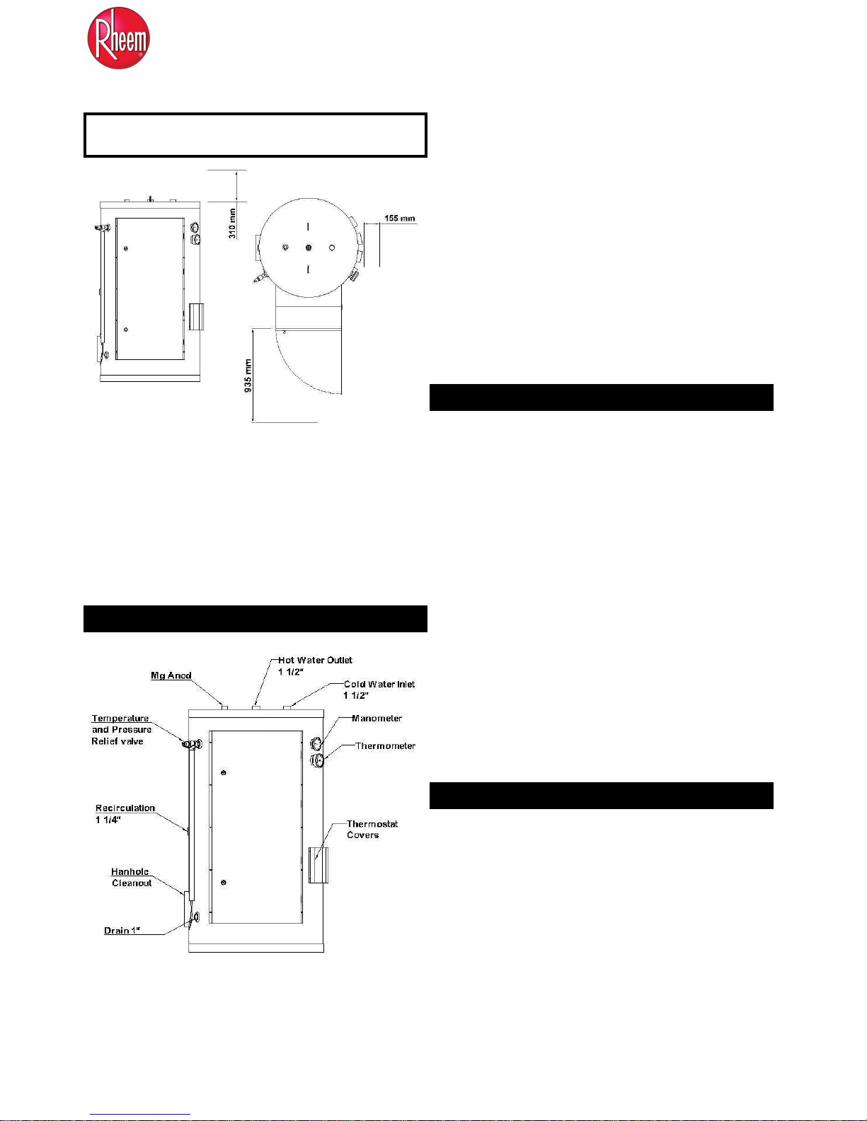
STORAGE TANK
This appliance uses AISI 304L quality stainless
steel tank to store the heated water for use. The
storage tank is constructed in accordance with the
ASME Boiler and Pressure Vessel Code
requirements. The volume capacity of storage
tank is approximately 1000 liters (265 gal).
Please refer to the attached mechanical general
arrangement dimensional drawing of storage tank.
The tank is furnished with threaded connections
for cold water inlet, hot water outlet, recirculation,
a relief valve and a drain connection.
The storage tank has a hand hole for ease of
inspection, cleanout and service. An optional
manhole may be specified for greater ease of
inspection.
A magnesium anode(s) is standard to help prevent
dissipation of the tank material by electrolytic
action.
JACKET ASSEMBLY
Outer Jacket – The outer jacket assembly is
constructed from steel, galvanized on both sides.
The galvanized surface is specially prepared and
phosphate coated to allow application of
electrostatic paint process. This coating
process insures a long life from the jacket
assembly. The storage tank is insulated by rock
wool material covered by outer jacket.
Page: 3 / 8
RELIEF VALVE
This water heater is supplied with a temperature
and pressure relief valve(s) sized in accordance
with ASME Boiler and Pressure Vessel Code,
Section IV. The relief valve(s) is installed in the
horizontal position and mounted in the tapping
provided in the storage tank. No valve is to be
placed between the relief valve and the water
heater. To prevent water damage, the discharge
from the relief valve must be piped to a suitable
floor drain for disposal when relief occurs. No
reducing couplings or other restrictions shall be
installed in the discharge line. The discharge line
shall allow complete drainage of the valve and
line. Relief valves should be manually operated at
least once a year. A relief valve that fails to
completely reseat and continues to discharge
water must be immediately replaced with a new,
properly sized, temperature and pressure relief
valve.
CAUTION: Avoid contact with hot
discharge water. Insure that no one is in
front of or around the relief valve discharge
line. Make sure that the extremely hot
water manually discharged from the relief
valve will not cause bodily injury or
property damage.
CAUTION:L EXPANSION OF WATER
THERMAL EXPANSION OF WATER
A relief valve that discharges periodically may be
due to thermal expansion in a closed system. A
water heater installed in a closed system, such as
one with a backflow preventer or check valve
installed in the cold water supply, shall be
provided with means to control expansion.
Contact the water supplier or local plumbing
inspector on how to correct this situation.
DO NOT plug or cap the relief valve.
ELECTRICAL CONNECTIONS
All installation procedures involving electric
power connection should only be performed by a
trained, certified electrician.
WARNING: WATER HEATER IS EQUIPPED
FOR OPERATION ON ONE VOLTAGE
ONLY. Check the rating plate on the front of the
control panel access for the correct voltage and
phase. DO NOT use this water heater with any
other voltage other than the voltage specified on
the rating plate. Failure to use the correct voltage
can cause problems that can result in death,
serious bodily injury or property damage.
CAUTION: THE SUPPLY VOLTAGE OF THE
WATER HEATER IS 415VAC, 3 PHASE,
60 HZ.
DO NOT CONNECT THE WATER HEATER
TO AN IMPROPER SOURCE OF
ELECTRICITY!
1. Use copper conductors only. All wiring
between the appliance and field installed
devices shall be made with copper wire
suitable for at least 75° C (167° F)
temperature rating.
2. The factory internal wiring is attached to a
terminal block inside the unit. The branch
circuit is connected to the terminal block
through an opening provided on the side of the
water heater electrical access panel.
3. Line voltage wire exterior to the appliance
must be enclosed in approved conduit or
approved metal clad cable.
4. To avoid serious damage, DO NOT energize
the appliance until the system is full of
water. Ensure that all air is removed from the
storage tank and piping before beginning
initial operation. Operation of a water heater
without a completely filled tank may result in
serious damage to the appliance and heating
element burn out.
5. The water heater should be connected with a
separate grounded branch circuit with over
current protection and disconnect switch. The
water heater should be grounded in
accordance with national and local codes. A
ground terminal is provided for ground
connection only.

Page: 4 / 8
6. Provide the appliance with proper overload
protection in the branch circuit. It is suggested
that the electrician size the branch circuit at
125 percent of the heater ampere rating and
further increase wire size as necessary to
compensate for voltage drop in long runs.
Branch circuit voltage drop should not exceed
3% at the heater.
7. Voltage applied to the heater should not vary
more than +5% to -10% of the model and
rating plate marking for satisfactory operation.
8. A wiring diagram is provided with the water
heater for the electrician’s use.
LOW WATER CUTOFF
This water heater is equipped with an electronic
low water cut-off installed at the factory. This low
water cut-off device uses a water level sensing
probe located above the heating element installed
in the highest point in the storage tank. If the
internal water level drops below this point, the
low water cut-off will shut down operation of the
heating elements. The electronic low water cut-off
has an LED located on its casing. This LED will
be illuminated and the control circuit will be
completed between the common and normally
open contacts on the relay unit when the sensing
probe is below the water level in the storage tank.
The operation of a low water cutoff should be
inspected every six months. For details refer to
electrical control circuit drawing attached to this
manuel.
STANDARD EQUIPMENT
Your commercial electric water heater is
equipped with the following as standard
equipment.
Low watt density immersion heating
elements with an stainless steel sheath.
Each heating element has 18 KW power
and two elements are grouped so the group
power is 36 KW. There are 4 groups of
elements making the total input power
144 KW.
Internal fusing of all elements in a
maximum of 48 amp increments provides
additional safety.
Electrostatic paint coated galvanized steel
outer jacket and electrical control panel are
provided.
Electrical control panel is provided with a
hinged door and key lock.
An AISI 304L stainless steel tank
constructed to ASME specifications and
provided with magnesium anode(s).
ASME rated temperature and pressure
relief valve provided by factory to ensure
safe heater operation.
Terminal block connections are installed
by the factory for safe easy wiring
connection.
Manual reset high water temperature limit
control.
Surface mounted mechanical thermostats
for each heater group. Max temperature
setting 162°F (72 °C)
3 year limited warranty provides
protection against failure of tanks due to
defects in material and workmanship in
commercial application.
Four groups of heating elements are
controlled by four regulating thermostats
as one thermostat for each group.
Time relays are provided to turn on the
heater groups in sequence with a user
defined time delay between each group.
Manual on-off switches for each heater
group with pilot lights.
Page: 5 / 8
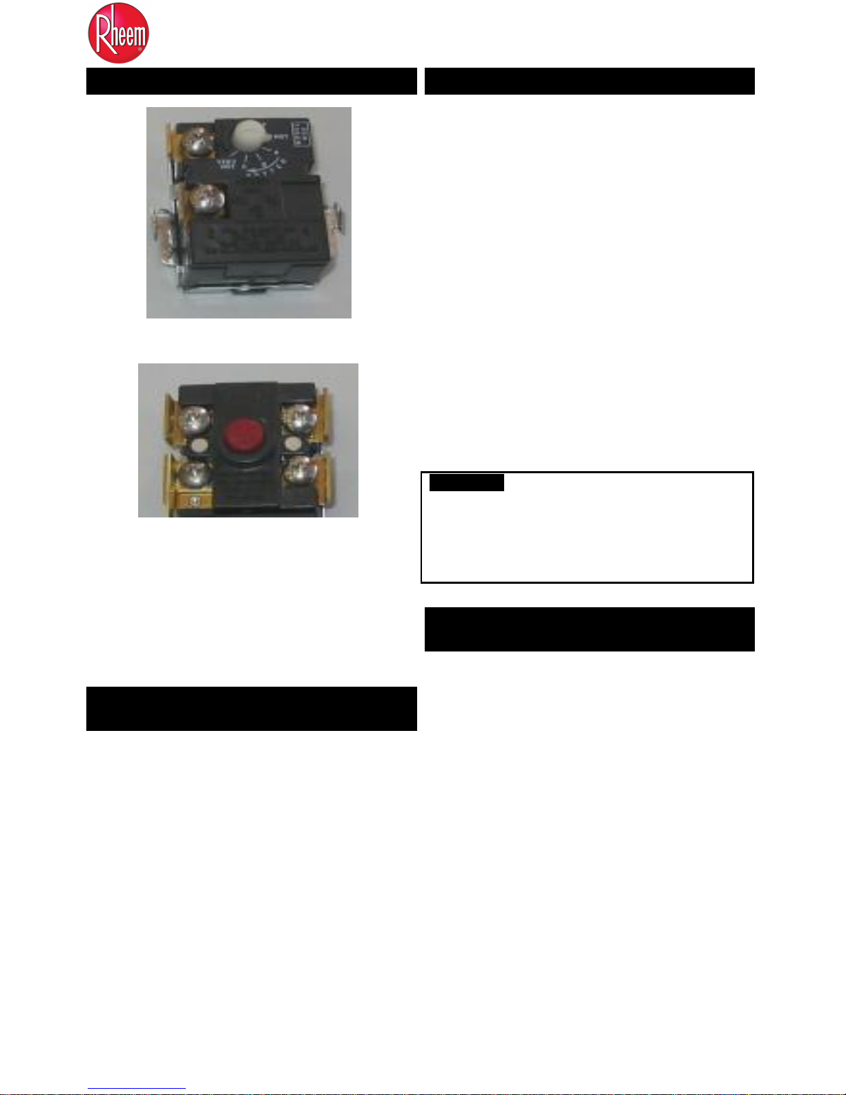
MECHANICAL THERMOSTATS
Temperature regulating thermostat
High Limit thermostat with manual reset
This water heater uses mechanical surface
mounted thermostats to activate magnetic
contactors allowing current to flow to the
immersion heating elements. The standard control
system uses one immersion thermostat for each
36kW of electric heating power in a water heater.
TEMPERATURE REGULATING
THERMOSTATS
This water heater has an adjustable thermostat to
control water temperature. The thermostat is
factory pre-set at approximately 125° F (51.7° C)
or less. Households with small children or
invalids may require a 120° F (48.9° C) or lower
temperature setting to reduce risk of scald injury.
Remember, no water heating system will provide
exact temperatures at all times. Allow a few days
of operation at the setting to determine the correct
temperature setting consistent with your needs.
WATER TEMPERATURE SETTINGS
1. Turn “OFF” the electrical power to the
water heater.
2. Open the thermostat cover on the tank.
3. Adjust each thermostat to the
desired temperature setting by turning the
adjusting knob from hot to very hot
position to increase the temperature.
When the knob is at very hot position the
adjusted temperature is max. 72 ° C. Each
thermostat will be factory pre-set to
approximately 125° F (51.7° C) or less as
shipped.
4. Close the thermostat cover.
5. Turn “ON” the electrical power to the
water heater.
WARNING:
HAZARD OF ELECTRICAL SHOCK –
Before opening the electrical access panel
to adjust the thermostat make sure the
electrical supply to the water heater is
turned “OFF”.
HIGH WATER TEMPERATURE
LIMIT CONTROL
The unit is equipped with a fixed setting, manual
reset high water temperature limit control. The
water heater temperature limit control has a fixed
limit setting of 180° F (82 ° C). If water
temperature exceeds the limit set point, the limit
will break the control circuit and shut down the
unit. The limit control can only be reset after the
water temperature has cooled below the set point
of the limit. The high water temperature limit
control is mounted on the surface of the tank,
above the heating element installed at the highest
point in the tank. The high limit control is reset
by pushing the red reset button on the control.
Operation of the limit control usually indicates a
major problem with the thermostat, contactors or
heating elements. Do not continue to push the
reset multiple times. The source of the problem
 Loading...