

Rheem 325, Rheemglas 551 325 05, Rheemglas 551 325 07, Rheemglas 551 325 Owne's Manual And Installation Instructions
Page 1
This water heater must be installed and serviced by an authorised person.
Please leave this guide with the householder.
Owners Guide
and
Installation Instructions
Air Sourced 325 Heat Pump
Water Heater
Page 2

PATENTS
This water heater may be protected by one or more patents or registered designs in the name of
Rheem Australia Pty Ltd.
TRADE MARKS
® Registered trademark of Rheem Australia Pty Ltd.
™ Trademark of Rheem Australia Pty Ltd.
Note: Every care has been taken to ensure accuracy in preparation of this publication.
No liability can be accepted for any consequences, which may arise as a result of its application.
Notice to Victorian Customers from the
Victorian Plumbing Industry Commission.
This water heater must be installed by a licensed person as required by the
Victorian Building Act 1993.
Only a licensed person will give you a Compliance Certificate, showing that the work complies with all the
relevant standards. Only a licensed person will have insurance protecting their workmanship for 6 years.
Make sure you use a licensed person to install this water heater and ask for your Compliance Certificate.
Page 3

3
CONTENTS
HOUSEHOLDER – We recommend you read pages 4 to 14.
The other pages are intended for the installer but may be of interest.
About Your Water Heater ............................................................................................................ 4
Regular Care ................................................................................................................................ 8
Water Supplies............................................................................................................................. 9
Save A Service Call ................................................................................................................... 12
Installation .................................................................................................................................. 15
Heat Pump And Tank Assembly .............................................................................................. 22
Connections – Plumbing .......................................................................................................... 31
Connections – Electrical ........................................................................................................... 33
Commissioning.......................................................................................................................... 35
Draining The Water Heater ....................................................................................................... 37
Warranty ..................................................................................................................................... 39
Page 4

4
ABOUT YOUR WATER HEATER
MODEL TYPE
Your Rheem® air sourced heat pump water heater is designed for outdoor installation only. The model you
have chosen is a Rheemglas® model.
The Rheem air sourced heat pump water heater has a vitreous enamel lined steel cylinder. The water
heater‟s evaporator absorbs heat from the surrounding air and transfers this heat into the water.
When hot water is drawn off and cold water enters the tank, the thermostat activates a fan, a compressor
and a circulator. The fan draws outside air in through the air inlet louvres at the side of the heat pump
module and the pump circulates water from the bottom of the storage tank through a heat exchanger. Heat is
absorbed from the air by an evaporator and transferred into the water through the heat exchanger. The
resulting cold air is then discharged through the air outlet grille back to atmosphere and the heated water is
circulated back into the storage tank. This process continues while ever heating is required until the water in
the storage tank reaches a temperature of 60°C.
Even on cloudy or cold days, heat is drawn from the surrounding air. The heat pump will operate when the
air temperature is between a minimum of 3°C to 5 C and maximum of 45 C to 55°C. The booster heating
unit will operate when the air temperature is below 3°C to 5°C or above 45°C to 55°C if heating is required.
The efficiency of the water heater increases as the surrounding air temperature increases.
Automatic safety controls are fitted to the water heater to provide safe and efficient operation.
ELECTRIC BOOSTING
Ice may begin to form on the evaporator when the air temperature falls
below 7 C, which will reduce the heat pump efficiency. At air temperatures
below 3°C to 5 C, the water heater deactivates the heat pump operation
and switches to the booster heating unit. The boost capacity in this mode is
100 litres.
The water inside the tank will be heated to a temperature of 70°C by the
electric booster heating unit if heating is required. During this period the
evaporator will defrost if necessary. The temperature setting of the
thermostat controlling the booster heating unit is not adjustable and is set
at 70°C.
MAINS PRESSURE
The water heater is designed to operate at mains pressure by connecting
directly to the mains water supply. If the mains supply pressure in your
area exceeds that shown on page 16, a pressure limiting valve must be
fitted. The supply pressure should be greater than 350 kPa for true mains
pressure operation to be achieved. A minimum water supply pressure of
200 kPa is required to enable the heat pump circulator and heat pump
system to operate effectively.
THERMAL CUT OUT
The refrigeration circuit is protected by thermal sensors. These will activate a thermal cut out in the event of
thermal surges or excessive heat in the refrigeration system.
If the thermal cut out has activated, the heat pump will not operate and the water heater will switch to booster
heating mode to ensure a supply of hot water. In booster heating mode, the booster heating unit will operate
regardless of the ambient air temperature, if heating of the water is required. The boost capacity of the
heating unit in booster heating mode is 100 litres and the water will be heated to 70°C.
The thermal cut out automatically resets when the refrigeration circuit cools down and the booster heating
unit has completed one heating cycle.
Page 5
ABOUT YOUR WATER HEATER
5
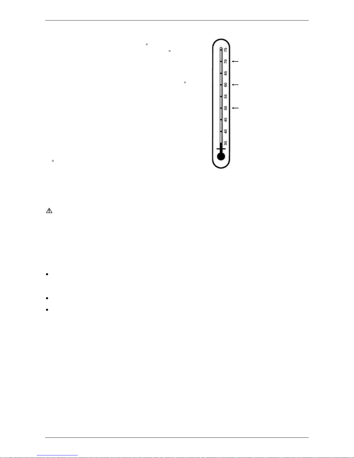
HOW HOT SHOULD THE WATER BE?
The system controls (compressor, evaporator and fan) will
operate until a water temperature of 60 C is reached. During
periods of ambient air temperature below 3°C to 5 C, the water
temperature is boosted automatically, if heating is required, by
the thermostatically controlled electric heating unit.
To meet the requirements of the National Plumbing Standard
the temperature of the stored water must not be below 60 C.
HOTTER WATER INCREASES THE RISK OF SCALD INJURY
This water heater can deliver water at temperatures which can
cause scalding. Check the water temperature before use, such
as when entering a shower or filling a bath or basin, to ensure it
is suitable for the application and will not cause scald injury.
We recommend and it may also be required by regulations that
an approved temperature limiting device be fitted into the hot
water pipe work to the bathroom and ensuite when this water
heater is installed. This will keep the water temperature below
50 C at the bathroom and ensuite. The risk of scald injury will
be reduced and still allow hotter water to the kitchen and
laundry.
TEMPERATURE ADJUSTMENT
The thermostats controlling the heat pump and the booster heating unit are factory set and not adjustable.
WARNING
This water heater is only intended to be operated by persons who have the experience or the knowledge and
the capabilities to do so. This water heater is not intended to be operated by persons with reduced physical,
sensory or mental capabilities i.e. the infirm, or by children. Children should be supervised to ensure they do
not interfere with the water heater.
This water heater uses 240 V AC electrical power for operation of the control systems and the electrically
operated components. The removal of the access cover(s) will expose 240 volt wiring. They must only be
removed by an authorised or qualified person.
Do not use aerosols, stain removers and household chemicals near the water heater whilst it is
working. Gases from some aerosol sprays, stain removers and household chemicals are corrosive to the
materials used in the heat pump system.
Do not store swimming pool chemicals, household cleaners, etc., near the water heater.
Ensure the air flow, air inlet louvres and outlet grille are not obstructed in any way at any time.
SAFETY
This water heater is supplied with a thermostat, two over-temperature energy cut-outs and a combination
temperature pressure relief valve. These devices must not be tampered with or removed. The water heater
must not be operated unless each of these devices is fitted and is in working order.
The operation of the over-temperature cut-out indicates a possibly dangerous situation. If the overtemperature cut-out operates, it must not be reset and the water heater must be serviced by an authorised or
qualified person.
If the electrical supply conduit to the water heater is damaged, it must be replaced by an authorised person
in order to avoid a hazard. Phone your nearest Rheem Service Department or Accredited Service Agent to
arrange for an inspection.
The warranty can become void if relief valves or other safety devices are tampered with or if the
installation is not in accordance with these instructions.
typical maximum temperature
from heat pump operation,
minimum recommended stored
water temperature
maximum recommended supply
temperature to bathrooms and
ensuites
booster temperature setting
Page 6
ABOUT YOUR WATER HEATER
6
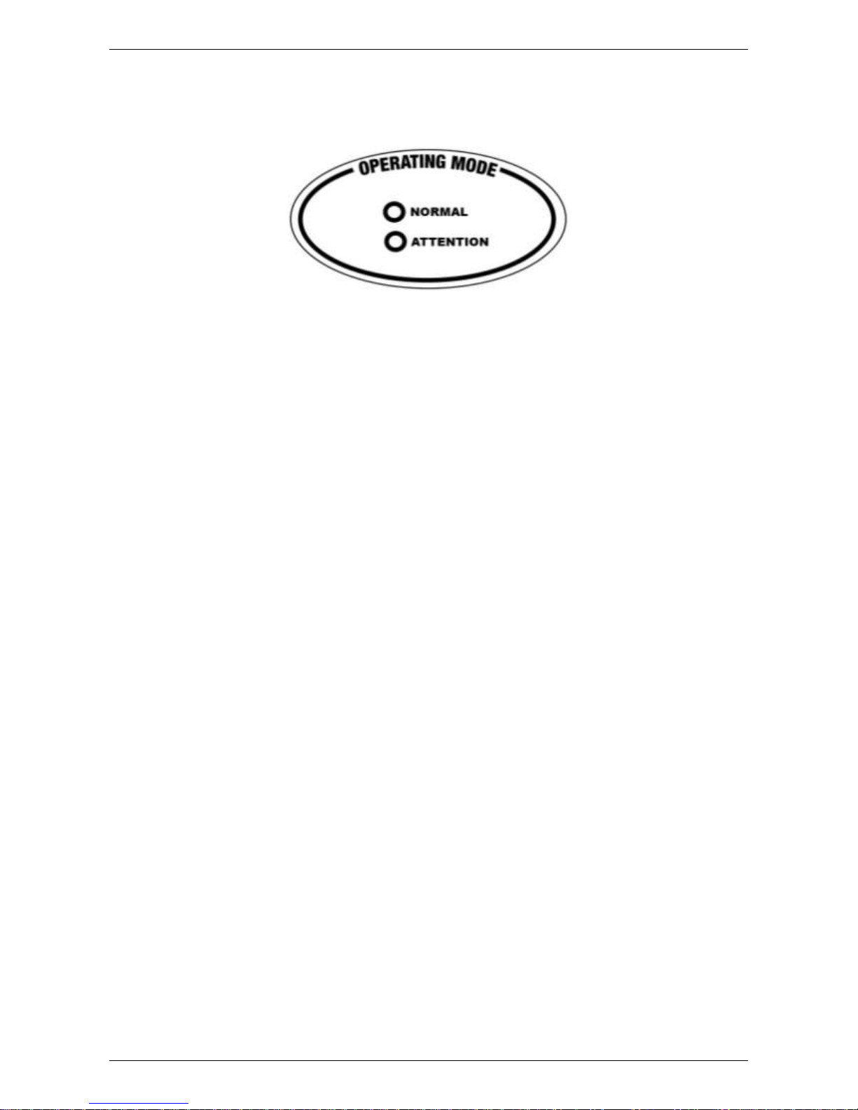
OPERATING MODE MONITOR
An operating mode monitor is located on the front of the heat pump module and houses a green and a red
LED.
The green LED, marked “normal”, indicates the operational mode of the heat pump water heater and the red
LED, marked “attention”, indicates a fault mode.
The green LED will emit either a constant glow or a series of flashes, with a 2 second interval between each
series. A series of long green flashes may also be emitted.
The red LED will emit a series of flashes, with a 2 second interval between each series, only if there is a
particular fault condition with the system.
The modes are:
Flashes
Operational Modes
solid green
(remains on)
Standby mode – waiting to heat
1 x green
Call for heating received – system checks performed
(heat pump heating or heating unit operation determined)
2 x green
Pump commences circulation at full speed
3 x green
Compressor and fan operation established
(heat pump operating)
long green
Heating unit on – ambient air temperature
below 3°C to 5°C or above 45°C to 55°C
no green
(remains off)
Call for service
If the power supply to the water heater is on and the green LED is off or the red LED is flashing, this
indicates there may be a fault with the water heater. The red LED may emit up to six flashes in each series of
flashes.
The fault which leads to the red LED flashing may be cleared when the heating cycle is complete and the
thermostat cuts power to the booster heating unit. The heat pump will then return to normal operation and
the green LED will commence operating. If the red LED continues or recommences to flash, count the
number of flashes and phone your nearest Rheem Service Department or Accredited Service Agent to
arrange for an inspection.
Note: Following a heating cycle by the booster heating unit, the thermostat opens circuit cutting power to the
booster heating unit and heat pump. When the thermostat next closes circuit switching power on to the heat
pump or if the electrical supply is switched off and on again at the isolating switch to the water heater, the red
LED will display the fault code for thirty (30) seconds that led to the booster heating unit being activated.
Page 7

ABOUT YOUR WATER HEATER
7
TIMER CONTROL
A timer can be installed in the electrical circuit to the water heater. The timer must be weatherproof if it is
installed outdoors. It may be desirable for the water heater not to operate between certain hours due to the
noise created by the system controls, such as during the night.
GOING ON HOLIDAYS
If you plan to be away from home for a few nights, we suggest you leave the water heater switched on. If you
plan to be away for a longer period, conserve energy by switching the isolating switch to the water heater off
(refer to “To Turn Off The Water Heater” on page 7).
TO TURN OFF THE WATER HEATER
If you plan to be away from home for only a few nights, we suggest you leave the water heater switched on.
If it is necessary to turn off the water heater:
Switch off the electrical supply at the isolating switch to the water heater.
Close the cold water isolation valve at the inlet to the water heater.
TO TURN ON THE WATER HEATER
Open the cold water isolation valve fully on the cold water line to the water heater.
Switch on the electrical supply at the isolating switch to the water heater.
The heat pump may take a few minutes to commence operating when the power supply is switched on. The
heat pump will only operate when the water in the storage tank requires heating and the heat pump
compressor is cool.
The booster heating unit will operate instead of the heat pump if the ambient air temperature is less than 3°C
to 5°C.
Note: The heat pump may not turn on after having just completed a heating cycle and more hot water is
drawn from the water heater. The heat pump will wait until the compressor has cooled down and the
conditions for start up are favourable in order to protect the compressor from damage. This may take up to
90 minutes from the last heating cycle.
HOW DO I KNOW IF THE WATER HEATER IS INSTALLED CORRECTLY?
Installation requirements are shown on page 20. The water heater must be installed by an authorised person
and the installation must comply with Standards AS/NZS 3500.4, AS/NZS 3000 and all local codes and
regulatory authority requirements. In New Zealand, the installation must conform with Clause G12 of the New
Zealand Building Code.
DOES THE WATER CHEMISTRY AFFECT THE WATER HEATER?
The water heater is suitable for most public water supplies, however some water chemistries may have
detrimental effects on the water heater and fittings. If you are in a known harsh water area you must read
page 9. If you are not sure, have your water chemistry checked against the conditions described on page 9.
HOW LONG WILL THE WATER HEATER LAST?
There are a number of factors that will affect the length of service the water heater will provide. These
include the water chemistry, the water pressure, temperature (inlet and outlet) and the water usage pattern.
However, your water heater is supported by a comprehensive warranty (refer to page 40).
ENVIRONMENT
At the end of the service life of the heat pump water heater and prior to the water heater being disposed of, a
person qualified to work with refrigerants must recover the refrigerant from within the sealed system. The
refrigerant must not be vented to atmosphere. Phone your nearest Rheem Service Department or Accredited
Service Agent to arrange for an inspection.
Page 8

8
REGULAR CARE
TEMPERATURE PRESSURE RELIEF VALVE
This valve is near the top of the water heater and is essential for its safe operation. It is possible for the valve
to release a little water through the drain line during each heating period. This occurs as the water is heated
and expands by approximately 1/50 of its volume.
Continuous leakage of water from the valve and its drain line may
indicate a problem with the water heater (refer to “Temperature
Pressure Relief Valve Running” on page 14).
Warning: Never block the outlet of this valve or its drain line for
any reason.
Operate the easing lever on the temperature pressure relief valve
once every six months. It is very important you raise and lower
the lever gently.
DANGER: Failure to do this may result in the water heater
cylinder failing, or under certain circumstances, exploding.
If water does not flow freely from the drain line when the lever is
lifted, then the water heater should be checked by your nearest
Rheem Service Department or Accredited Service Agent.
The temperature pressure relief valve should be checked for
performance or replaced at intervals not exceeding 5 years, or more
frequently in areas where there is a high incidence of water deposits
(refer to “Water Supplies” on page 9).
EXPANSION CONTROL VALVE
In many areas, including South Australia, Western Australia and
scaling water areas, an expansion control valve is fitted to the cold
water line to the water heater. The expansion control valve may
discharge a small quantity of water from its drain line during the
heating period instead of the temperature pressure relief valve on
the water heater.
Operate the easing lever on the expansion control valve once every six months. It is very important you
raise and lower the lever gently. The expansion control valve should be checked for performance or
replaced at intervals not exceeding 5 years, or more frequently in areas where there is a high incidence of
water deposits.
HEAT PUMP SYSTEM
It is recommended the evaporator and refrigeration system is checked every five years. In particularly dusty
environments, it may be necessary to have the heat pump system checked and cleaned of dust and residue
on a more regular basis.
water
heater
drain
line
lift until water
flows from the
drain line –
lower gently
Page 9
9
WATER SUPPLIES
Water heaters must be installed in accordance with this advice to be covered by the warranty.
A Rheem water heater is manufactured to suit the water conditions of most public reticulated water supplies.
However, there are some known water supplies which can have detrimental effects on the water heater and
its operation and/or life expectancy. If you are unsure of your water chemistry, you may be able to obtain
information from your local water supply authority. This water heater should only be connected to a water
supply which complies with these guidelines for the water heater warranty to apply.
ANODE
The vitreous enamel lined mild steel cylinder of the water heater is covered by warranty where the total
dissolved solids (TDS) content in the water is less than 2500 mg/L and when the correct colour coded anode
is used. The use of an incorrect colour coded anode will void the cylinder warranty and may shorten the life
of the water heater cylinder.
The correct colour coded anode should be selected and fitted to the water heater in accordance with the
following advice and the “Water Chemistry Charts” for TDS on page 11.
Total Dissolved Solids
Anode colour code
0 – 40 mg/L
Green
40 – 150 mg/L
Green or Black
150 – 400 mg/L
Black
400 – 600 mg/L
Black or Blue
600 – 2500 mg/L
Blue
2500 mg/L +
Blue (no cylinder warranty)
The changing of anodes must be carried out by a plumber or authorised service person.
Note: Some water analysis reports may state the conductivity of the water rather than the level of total
dissolved solids. Conductivity, measured in microsiemens per centimetre (µS / cm), is directly proportional to
the TDS content of the water. TDS, in mg / L, is approximately 70% of the conductivity in µS / cm.
ANODE INSPECTION
The anode(s) installed in a vitreous enamel lined mild steel water heater cylinder will slowly dissipate whilst
protecting the cylinder. The life of the cylinder may be extended by arranging for an authorised person to
inspect the anode(s) and replace if required.
The suggested maximum time after installation when the anode(s) should be inspected in the heat pump is 8
years.
For water supplies which are either softened, desalinated, of poor chemistry or where the water supply may
alternate between rainwater tank and a reticulated public supply or another supply, it is recommended the
anode(s) be inspected 3 years earlier than shown (refer to “Anode” on page 9).
It is recommended the anode be inspected during a five year service of the water heater, if one is conducted.
Page 10

WATER SUPPLIES
10
CAUTION
If the water supply has a TDS greater than 150 mg/L and a green anode has not been changed to a black
anode, or if the TDS is greater than 600 mg/L and the anode has not been changed to a blue anode, there is
the possibility the anode may become overactive and hydrogen gas could accumulate in the top of the water
heater during long periods of no use. In areas where this is likely to occur, the installer should instruct the
householder on how to dissipate the gas safely.
If, under these conditions, the water heater has not been used for two or more weeks the following procedure
should be carried out before using any electrical appliances (automatic washing machines and dishwashers)
which are connected to the hot water supply.
The hydrogen, which is highly flammable, should be vented safely by opening a hot tap and allowing the
water to flow. There should be no smoking or naked flame near the tap whilst it is turned on. Any hydrogen
gas will be dissipated. This is indicated by an unusual spurting of the water from the tap. Once the water runs
freely again, any hydrogen in the system will have been released.
SATURATION INDEX
The saturation index (SI) is used as a measure of the water‟s corrosive or scaling properties.
In a corrosive water supply, the water can attack copper parts and cause them to fail. Where the saturation
index is less than –1.0, the water is very corrosive and warranty does not apply to a copper sheathed heating
unit. A corrosion resistant heating unit must be used. An expansion control valve may need to be fitted on
the cold water line after the non-return valve in a corrosive water area where there are sufficient quantities of
silica dissolved in the water.
In a scaling water supply calcium carbonate is deposited out of the water onto any hot metallic surface.
Where the saturation index exceeds +0.40, the water is very scaling. An expansion control valve must be
fitted on the cold water line after the non-return valve to protect and for warranty to apply to the temperature
pressure relief valve and water heater cylinder.
Where the saturation index exceeds +0.80, warranty does not apply to a standard watts density heating unit
or a heat pump heat exchanger. A low watts density heating unit must be used. Water with an SI greater
than +0.80 may be treated with a water softening device to reduce the SI of the water.
Contact your nearest Rheem Service Department or Accredited Service Agent if a replacement heating unit
is required.
Refer to the cold water connection detail on page 31 for the position of the expansion control valve.
CHLORIDE AND PH
In a high chloride water supply, the water can corrode stainless steel parts and cause them to fail. Where the
chloride level exceeds 250 mg/L warranty does not apply to a heat pump‟s stainless steel heat exchanger.
pH is used as a measure of the water‟s alkalinity and acidity. In an acidic water supply, the water can attack
stainless steel parts and cause them to fail. No warranty applies to a heat pump‟s stainless steel heat
exchanger where the pH is less than 6.0. Water with a pH less than 6.0 may be treated to raise the pH.
The water supply from a rainwater tank in a metropolitan area is likely to be corrosive due to the dissolution
of atmospheric contaminants. This may result in pH of less than 6.0 and warranty would not apply to a heat
pump‟s stainless steel heat exchanger. It is recommended an analysis on the water from a rainwater tank be
conducted prior to connecting this type of water supply to a water heater with a stainless steel heat
exchanger.
CHANGE OF WATER SUPPLY
The changing or alternating from one water supply to another can have a detrimental effect on the operation
and / or life expectation of a water heater cylinder, a temperature pressure relief valve, a heating unit and a
heat exchanger in a heat pump water heater.
Where there is a changeover from one water supply to another, eg, a rainwater tank supply, desalinated
water supply, public reticulated water supply or water brought in from another supply, then water chemistry
information should be sought from the supplier or it should be tested to ensure the water supply meets the
requirements given in these guidelines for warranty to apply.
Page 11

WATER SUPPLIES
11
WATER CHEMISTRY CHARTS
CONDUCTIVITY - µS/cm
TOTAL DISSOLVED SOLIDS & CONDUCTIVITY
40 150 400 600
TOTAL DISSOLVED SOLIDS (TDS) - mg/L
ANODE SELECTION
warranty applies to a vitreous enamel lined water heater cylinder if the
correct coloured anode is used for the TDS / conductivity level of water
2500
3570
NO WARRANTY
APPLIES
to a vitreous
enamel lined
water heater
cylinder
Blue
Black
or
Orange
Green
60 215 570 860
-1.0
No warranty applies to a
temperature pressure relief valve or a
water heater cylinder unless an
expansion control valve is fitted.
No warranty applies to a:
-copper sheathed heating unit
-open circuit solar collector
-copper cylinder or tank
SATURATION INDEX (SI)
WITHIN WARRANTY
SPECIFICATION
SATURATION INDEX
(measured @ 80°C water temperature)
corrosive scaling
No warranty applies to a:
-standard watts density heating unit
-open circuit solar collector
-heat pump heat exchanger
-copper cylinder or tank
+0.4 +0.80
0
0
-1.0
No warranty applies to a
temperature pressure relief valve or a
water heater cylinder unless an
expansion control valve is fitted.
No warranty applies to a:
-copper sheathed heating unit
-open circuit solar collector
-copper cylinder or tank
SATURATION INDEX (SI)
WITHIN WARRANTY
SPECIFICATION
SATURATION INDEX
(measured @ 80°C water temperature)
corrosive scaling
No warranty applies to a:
-standard watts density heating unit
-open circuit solar collector
-heat pump heat exchanger
-copper cylinder or tank
+0.4 +0.80
WITHIN WARRANTY
SPECIFICATION
4.0 5.0 6.0 7.0 8.0 9.0
350
300
250
200
150
100
50
CHLORIDES
pH & CHLORIDES
acidic alkaline
pH
to a stainless steel water heater
cylinder or to a stainless steel
heat exchanger
NO WARRANTY APPLIES
to a stainless steel water heater cylinder
or to a stainless steel heat exchanger
NO WARRANTY APPLIES
CONDUCTIVITY - µS/cm
TOTAL DISSOLVED SOLIDS & CONDUCTIVIT Y
40 150 400 600
TOTAL DISSOLVED SOLIDS (TDS) - mg/L
ANODE SELECTION
warranty applies to a vitreous enamel lined water heater cylinder if the
correct coloured anode is used for the TDS / conductivity level of water
2500
3570
NO WARRANTY
APPLIES
to a vitreous
enamel lined
water heater
cylinder
Blue
Black
or
Orange
Green
60 215 570 860
-1.0
No warranty applies to a
temperature pressure relief valve or a
water heater cylinder unless an
expansion control valve is fitted.
No warranty applies to a:
-copper sheathed heating unit
-open circuit solar collector
-copper cylinder or tank
SATURATION INDEX (SI)
WITHIN WARRANTY
SPECIFICATION
SATURATION INDEX
(measured @ 80°C water temperature)
corrosive scaling
No warranty applies to a:
-standard watts density heating unit
-open circuit solar collector
-heat pump heat exchanger
-copper cylinder or tank
+0.4 +0.80
0
0
0
Page 12
12
SAVE A SERVICE CALL
Check the items below before making a service call. You will be charged for attending to any condition or
fault that is not related to manufacture or failure of a part.
NOT ENOUGH HOT WATER (OR NO HOT WATER)
Is the electricity switched on?
Inspect the isolating switch marked “HOT WATER” or “WATER HEATER” at the switchboard and the
isolating switch (if one is installed) at the water heater and ensure they are turned on.
Check the fuse marked “HOT WATER” or “WATER HEATER” at the switchboard.
Is a timer installed?
If a timer has been installed, ensure sufficient time has been allowed to reheat the storage tank.
Are you using more hot water than you think?
Is one outlet (especially the shower) using more hot water than
you think?
Very often it is not realised the amount of hot water used,
particularly when showering. Carefully review the family‟s hot
water usage. As you have installed an energy saving appliance,
energy saving should also be practised in the home.
Adjust your water usage pattern to take advantage of maximum
energy gains. Have your plumber install a flow control valve to
each shower outlet to reduce water usage.
Heat pump controller or circulator has failed
Has the heat pump controller or circulator failed?
The heat pump will not operate and the water heater will switch to backup heating mode. The boost
capacity of the heating unit in backup heating mode is 100 litres.
Refer to “Heat Pump Is Not Operating” on page 13.
Phone your nearest Rheem Service Department or Accredited Service Agent to arrange for an
inspection.
Temperature pressure relief valve running
Is the relief valve discharging too much water?
Refer to “Temperature Pressure Relief Valve Running” on page 14.
Water heater size
Do you have the correct size water heater for your requirements?
The sizing guide in the sales literature and on the Rheem website (www.rheem.com.au) suggests
average sizes that may be needed.
WATER NOT HOT ENOUGH
You may find that due to heavy hot water usage the water temperature may be lower than normally
expected, due to insufficient heating time being allowed. You will need to carefully plan your use of the hot
water on such occasions.
Page 13

SAVE A SERVICE CALL
13
WATER TOO HOT
The water heater, during heat pump operation will heat the water to a temperature of 60°C. In booster mode,
the boost capacity of the heating unit is 100 litres and the water will be heated to 70°C.
The booster heating unit will operate during periods of cold ambient temperatures below 3°C to 5°C. This is
normal operation.
If a heat pump component has failed, the heat pump will not operate and the water heater will switch to
backup heating mode to ensure a supply of hot water. In backup heating mode, the booster heating unit and
its controlling thermostat will operate regardless of the ambient air temperature, if heating of the water is
required. The red LED will flash to indicate a fault may have occurred.
If the water is being heated to 70°C, the ambient air temperature has not fallen below 3°C to 5 °C, the heat
pump has not been operating and the red LED is flashing, phone your nearest Rheem Service Department
or Accredited Service Agent to arrange for an inspection.
HEAT PUMP IS NOT OPERATING
Air temperature is cold
The heat pump will not operate when the air temperature is below 3°C to 5°C, the booster heating unit
will operate instead. The boost capacity of the heating unit in booster heating mode is 100 litres and the
water will be heated to 70°C during these periods. Heating of the water by the heat pump will
recommence after the heating element has completed its heating cycle, the air temperature increases to
3°C to 5°C or higher and heating of water is required.
Thermal cut out activated
Has the thermal cut out for the heat pump compressor activated and the red LED is flashing a series of
single flashes?
If the thermal cut out has activated, the heat pump will not operate, the red LED will flash a series of
single flashes and the water heater will switch to booster heating mode to ensure a supply of hot water.
In booster heating mode with the thermal cut out for the heat pump compressor activated, the booster
heating unit will operate if heating of the water is required, regardless of the ambient air temperature.
The boost capacity of the heating unit in booster heating mode is 100 litres and the water will be heated
to 70°C.
The thermal cut out will reset itself when the compressor cools down. To check whether there may be a
problem, open a hot tap and allow to run for ten to fifteen minutes. The heat pump, if working properly,
will activate and continue operating to heat the water. Close the hot tap when the heat pump begins to
operate.
However, if the heat pump deactivates within five minutes and the red LED commences to flash again,
there may be a problem. Phone your nearest Rheem Service Department or Accredited Service Agent
to arrange for an inspection.
Heat pump controller or circulator has failed
Has a heat pump component failed and the red LED is flashing?
If a heat pump component has failed, the heat pump will not operate, the red LED will flash and the
water heater will switch to backup heating mode to ensure a supply of hot water. In backup heating
mode, the booster heating unit and its controlling thermostat will operate if heating of the water is
required, regardless of the ambient air temperature. The boost capacity of the heating unit in backup
heating mode is 100 litres and the water will be heated to 70°C.
Count the number of flashes from the red LED and phone your nearest Rheem Service Department or
Accredited Service Agent to arrange for an inspection.
EXPANSION CONTROL VALVE RUNNING
If an expansion control valve is fitted in the cold water line to the water heater (refer to page 31) it may
discharge a small quantity of water instead of the temperature pressure relief valve on the water heater. The
benefit is that energy is conserved as the discharged water is cooler.
Page 14

SAVE A SERVICE CALL
14
TEMPERATURE PRESSURE RELIEF VALVE RUNNING
Normal Operation
It is normal and desirable this valve allows a small quantity of
water to escape during the heating cycle. However, if it discharges
more than a bucket full of water in 24 hours, there may be another
problem.
Continuous dribble
Try gently raising the easing lever on the relief valve for a few
seconds (refer to “Temperature Pressure Relief Valve” on page 8).
This may dislodge a small particle of foreign matter and clear the
fault. Release the lever gently.
Steady flows for long periods (often at night)
This may indicate the mains water pressure sometimes rises
above the designed pressure of the water heater. Ask your
installing plumber to fit a pressure limiting valve.
Warning: Never replace the relief valve with one of a higher pressure rating.
Heavy flows of hot water until the water heater is cold - then stops until water reheats
The water heater must be switched off at the isolating switch or switchboard. Phone your nearest
Rheem Service Department or Accredited Service Agent to arrange for an inspection.
HIGH ELECTRICITY BILLS
With the installation of your new air sourced heat pump water heater, maximum electrical energy savings can
be achieved. Should you at any time, feel your electricity account is too high, we suggest you check the
following points:
Is the water heater operating in booster mode with the red LED flashing?
If there is a fault with the heat pump system, the water heater will default to backup heating mode to
ensure a supply of hot water. Check to see if the red LED is flashing as this will indicate there may be a
fault with the system.
Refer to “Water Too Hot” on page 13 and to “Heat Pump Is Not
Operating” on page 13.
Is the relief valve running excessively?
Refer to “Temperature Pressure Relief Valve Running” on
page 14.
Is one outlet (especially the shower) using more hot water than
you think?
Refer to “Not Enough Hot Water” on page 12.
Is there a leaking hot water pipe, dripping hot water tap, etc?
Even a small leak will waste a surprising quantity of hot water and energy. Replace faulty tap washers,
and have your plumber rectify any leaking pipe work.
Consider recent changes to your hot water usage pattern and check if there has been any increase in
tariffs since your previous account.
The heat pump water heater operates at its most efficient at higher air temperatures. Prolonged periods
where the temperature is below 3°C to 5 C will decrease the efficiency of the system and increase
running costs.
IF YOU HAVE CHECKED ALL THE FOREGOING AND STILL BELIEVE YOU NEED ASSISTANCE, CALL
YOUR NEAREST RHEEM SERVICE DEPARTMENT OR ACCREDITED SERVICE AGENT.
Page 15

15
INSTALLATION
THIS WATER HEATER IS FOR OUTDOOR INSTALLATON ONLY.
THIS WATER HEATER IS NOT SUITABLE FOR POOL HEATING.
STORAGE TANK AND HEAT PUMP MODULE
The heat pump water heater is made of two main components, the storage tank and the heat pump module.
For transport and handling (weight) purposes both items are shipped separately and designed to be
assembled at the installation site. The water heater must not be operated until both components are
assembled. Refer to “Heat Pump and Tank Assembly” on page 22.
Take care when handling the heat pump module. The jacket of the heat pump module needs to be handled
gently so as not to cause damage.
Care must be taken during transportation and handling. Do not lay the heat pump module down and
do not tilt the heat pump module or the heat pump and storage tank assembly more than 30° from the
vertical. This will displace the compressor lubricating oil. If the heat pump module or heat pump and storage
tank assembly has been tilted more than 30° from the vertical during handling, it will need one hour to drain
back before the power to the water heater can be switched on, otherwise damage to the compressor may
result.
WATER HEATER LOCATION
The water heater is suitable for outdoor installation only. The water heater should be installed close to the
most frequently used outlet and its position chosen with noise, safety and service in mind. Make sure people
(particularly children) will not accidentally touch the air inlet louvres and outlet grille and that they are clear of
obstructions and shrubbery.
It is advisable to install the water heater away from
bedroom or living room windows as the system controls
can generate a level of noise whilst they are operating.
Consider the location in relation to neighbours‟ bedrooms
and living room windows.
Clearance must be allowed for servicing of the water
heater. The water heater must be accessible without the
use of a ladder or scaffold. Make sure the temperature
pressure relief valve lever is accessible and the top and
front covers, system controls and thermostat can be
removed for service.
You must be able to read the information on the rating
plate. If possible leave headroom of one water heater
height so the anodes can be inspected or replaced.
Remember you may have to remove the entire water
heater later for servicing.
The water heater must be installed with a clearance of at least 100 mm from a wall. A clearance of 300 mm
is required perpendicular from both the front air inlet louvres and the outlet grille to any wall or obstruction.
Refer to the dimensions diagram on page 21. The heat pump storage tank and module must be installed on
a slab or solid base of a minimum 900 mm wide x 650 mm deep. The heat pump module must be firmly
supported by the slab or solid base.
The installation must comply with the requirements of AS/NZS 3500.4, AS/NZS 3000 and all local codes and
regulatory authority requirements. In New Zealand, the installation must conform with Clause G12 of the New
Zealand Building Code. It is recommended the heat pump water heater be installed at ground or floor level
and must stand vertically upright.
The water heater must not be installed in an area with a corrosive atmosphere where chemicals are stored or
where aerosol propellants are released. Remember the air may be safe to breathe, but the chemicals may
attack the materials used in the heat pump system.
Page 16

INSTALLATION
16
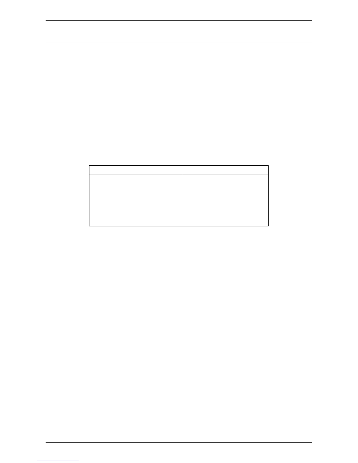
MAINS WATER SUPPLY
Where the mains water supply pressure exceeds that shown in the table below, an approved pressure
limiting valve is required and should be fitted as shown in the installation diagram (refer to diagram on
page 31).
Model
325
Relief valve setting
1000 kPa
Expansion control valve setting *
850 kPa
Max. mains supply pressure
With expansion control valve
680 kPa
Without expansion control valve
800 kPa
Min. mains supply pressure
200 kPa
* Expansion control valve not supplied with the water heater.
TANK WATER SUPPLY
If the water heater is supplied with water from a tank supply and a minimum water supply pressure of
200 kPa at the water heater cannot be achieved, then a pressure pump system must be installed to allow the
heat pump circulator to operate and avoid air locks in the circuit. Care must be taken to avoid air locks. The
cold water line from the supply tank should be adequately sized and fitted with a full flow gate valve or ball
valve.
Page 17

INSTALLATION
17
HOT WATER DELIVERY
This water heater can deliver water at temperatures which can cause scalding.
It is necessary and we recommend that a temperature limiting device be fitted between the water heater and
the hot water outlets in any ablution area such as a bathroom or ensuite, to reduce the risk of scalding. The
installing plumber may have a legal obligation to ensure the installation of this water heater meets the
delivery water temperature requirements of AS/NZS 3500.4 so that scalding water temperatures are not
delivered to a bathroom, ensuite or other ablution area.
The temperature limiting device used with a solar water heater should have a specified minimum
temperature differential, i.e. between the hot water inlet and the tempered water outlet, of no greater than
10°C.
Where a temperature limiting device is installed adjacent to the water heater, the cold water line to the
temperature limiting device can be branched off the cold water line either before or after the isolation valve,
pressure limiting valve and non return valve to the water heater. If an expansion control valve is required, it
must always be installed after the non return valve and be the last valve prior to the water heater.
If a pressure limiting valve is installed on the cold water line to the water heater and the cold water line to a
temperature limiting device branches off before this valve or from another cold water line in the premises,
then a pressure limiting valve of an equal pressure setting may be required prior to the temperature limiting
device.
Two Temperature Zones Using a Temperature Limiting Device
Page 18

INSTALLATION
18
CIRCULATED HOT WATER FLOW AND RETURN SYSTEM
A heat pump water heater should not be installed as part of a circulated hot water flow and return system in a
building.
If a circulated flow and return system is required, it is necessary to bypass the heat pump water heater and
install a secondary water heater connected to the hot water flow and return line and supplied from the heat
pump water heater. The secondary water heater must be a storage water heater able to provide a hot water
outlet temperature of at least 60 C. Note: The thermostat must always be set to at least 60 C. Refer to the
diagram on page 18.
Temperature Limiting Device
A temperature limiting device cannot be installed in circulated hot water flow and return pipe work. The
tempered water from a temperature limiting device cannot be circulated. Where a circulated hot water flow
and return system is required in a building, a temperature limiting device can only be installed on a dead leg,
branching off the circulated hot water flow and return pipe.
If circulated tempered water were to be returned back to the water heater, depending on the location of the
return line connection on the water supply line to the water heater, then either:
water will be supplied to the cold water inlet of the temperature limiting device at a temperature
exceeding the maximum recommended water supply temperature, or
when the hot taps are closed no water will be supplied to the cold water inlet of the temperature limiting
device whilst hot water will continue to be supplied to the hot water inlet of the temperature limiting
device.
These conditions may result in either water at a temperature exceeding the requirements of AS/NZS 3500.4
being delivered to the hot water outlets in the ablution areas, or the device closing completely and not
delivering water at all, or the device failing. Under either condition, the operation and performance of the
device cannot be guaranteed.
Circulated Hot Water Flow and Return System – Heat Pump Water Heater
Page 19

INSTALLATION
19
REDUCING HEAT LOSSES
The cold water line to and the hot water line from the water heater must be insulated in accordance with the
requirements of AS/NZS 3500.4. The insulation must be weatherproof and UV resistant if exposed.
ANODE TYPES
The vitreous enamel lined cylinder of this water heater is covered by warranty where the total dissolved
solids (TDS) content in the water is less than 2500 mg/L and when the correct colour coded anode is used.
The use of an incorrect colour coded anode may shorten the life of the water heater cylinder and will void the
cylinder warranty.
The correct colour coded anode for the water supply being used must be selected and fitted in the water
heater. Refer to “Water Supplies” on page 9 and the “Water Chemistry Charts” for TDS on page 11. The
black anode is fitted as standard.
Total Dissolved Solids
Anode colour code
0 – 40 mg/L
Green
40 – 150 mg/L
Green or Black
150 – 400 mg/L
Black
400 – 600 mg/L
Black or Blue
600 – 2500 mg/L
Blue
2500 mg/L +
Blue (no cylinder warranty)
If the water supply has a TDS greater than 150 mg/L and a green anode has not been changed to an orange
or black anode, or if the TDS is greater than 600 mg/L and the anode has not been changed to a blue anode,
there is the possibility the anode may become overactive and hydrogen gas could accumulate in the top of
the water heater during long periods of no use. In areas where this is likely to occur, the installer should
instruct the householder on how to dissipate the gas safely (refer to “Caution” on page 10).
SADDLING - PIPE WORK
To prevent damage to the cylinder when attaching pipe clips or saddles to the water heater jacket, we
recommend the use of self-drilling screws with a maximum length of 13 mm. Should pre drilling be required,
extreme caution must be observed when penetrating the jacket of the water heater.
Note: Damage to the cylinder as a result of saddling to the jacket will void the warranty.
Page 20

INSTALLATION
20
TYPICAL INSTALLATON – OUTDOOR LOCATION
Page 21

INSTALLATION
21
DIMENSIONS AND TECHNICAL DATA
1631
1317
1018
32°
574
HOT
OUTLET
COLD
INLET
114
546
871
863
619 245
100
WALL
AIR
INLET
AIR INLET
638
AIR
OUTLET
300 MIN
VENTILATION
CLEARANCE
CONDENSATE DRAIN
TPR
VALVE
AIR INLET
AIR
OUTLET
300 MIN
162
300 MIN
ELECTRICAL
CONNECTION
VENTILATION
CLEARANCE
System number
551 325
Part numbers
Model number 2.4 kW
551 325 05 Tank only 2.4 kW
T551 325 05
3.6 kW
551 325 07 Tank only 3.6 kW
T551 325 07
Heat pump module
180550
Maximum rated power input
3600 watts
Storage capacity
325 litres
Rated heat pump power input
800 watts
Boost capacity
100 litres
Booster element rating
2400 or 3600 watts
Mass empty - total
136 kg
Refrigerant type
R134a
Storage tank
88 kg
Refrigerant circuit pressure
3000 kPa Heat pump module
48 kg
Mass full - total
461 kg
Specifications are subject to change with ongoing product improvements.
Page 22

22
HEAT PUMP AND TANK ASSEMBLY
STORAGE TANK AND HEAT PUMP MODULE
The heat pump water heater is made of two main components, the storage tank and the heat pump module.
For transport and handling (weight) purposes both items are shipped separately and designed to be
assembled at the installation site. The water heater must not be operated until both components are
assembled. Both the storage tank and heat pump module must sit on a slab or solid base.
HEAT PUMP MODULE
The heat pump module is shipped in a box containing two hand holes to facilitate easy handling lifting. The
heat pump module is to be mounted against the side of the storage tank and must be fully supported by a
slab or solid base.
STORAGE TANK
The storage tank is designed to receive the heat pump module. There are two water fittings located at the
side of the storage tank to which water hoses from the heat pump module are connected. A power cable and
a tank sensor cable also protrude from the lower cover of the storage tank. These are connected to the heat
pump module during the assembly procedure.
storage tank heat pump module heat pump water heater
+
=
Page 23

HEAT PUMP AND TANK ASSEMBLY
23
ASSEMBLY PROCEDURE
Warning: The heat pump must be assembled, plumbed and filled with water prior to power being
connected and switched on.
The following procedure should be followed to properly place the heat pump module in position and connect
to the storage tank:
1. Remove all packaging and position the storage tank in its intended location.
The storage tank must be positioned at least 100 mm from the wall. If a minimum clearance of 100 mm
is not allowed for, the heat pump module will not be able to be completely connected to the storage tank.
The water connections may be on either the left or right hand side, parallel to the wall.
32°
574
619 245
100
WALL
AIR
INLET
AIR INLET
638
AIR
OUTLET
300 MIN
VENTILATION
CLEARANCE
CONDENSATE DRAIN
TPR
VALVE
300 MIN
Step 1
position storage tank at least 100 mm from the wall
2. Remove the two screws securing the lower front cover to the storage tank.
Remove the lower front cover from the storage tank.
Step 2 Step 3
remove screws withdraw the power cable
from lower front cover and tank sensor cable
3. Withdraw the power cable and tank sensor cable, housed behind the lower front cover, from the
opening.
Page 24

HEAT PUMP AND TANK ASSEMBLY
24
4. Connect the mains power supply wiring to the terminal block and earth connection inside of the lower
front cover.
Secure the conduit to the side of the storage tank with a saddle clamp.
The saddle clamp must be positioned over the pilot holes provided, otherwise the conduit will
interfere with the heat pump module installation.
Refer to “Connections – Electrical” on page 33.
Note: The power supply to the water heater must not be switched on until the installation is complete,
the water heater is filled with water and a satisfactory megger reading is obtained.
Step 4
Connect wiring and secure conduit with saddle clamp
5. Refit the lower front cover.
6. Position the heat pump module near its installed position at the storage tank and remove the carton.
CAUTION: The heat pump module weighs approximately 48 kg. Use the hand holes provided in the
sides of the packaging. Good lifting practice should be followed.
Page 25

HEAT PUMP AND TANK ASSEMBLY
25
7. Retrieve the drain pipe kit from inside of the heat pump module.
Feed the hose through the penetration on the side of the heat pump module
Slip the hose clamp over the upper end of the hose within the heat pump module
Push the hose over the spigot on the condensate tray located below the evaporator
Secure the hose to the spigot with the hose clamp
Extend the hose away from the base of the storage tank and heat pump module using standard
12 mm irrigation fittings
Secure the hose to the side of the heat pump module with a saddle clamp.
Step 7
feed hose through penetration secure hose to the spigot secure hose with saddle clamp
8. Remove the two screws securing the front cover to the heat pump module.
Remove the front cover from the heat pump module.
Steps 8 and 10
remove front cover from heat pump module and feed through cables
9. Position the edge of the heat pump module which is closest to the wall against the storage tank so the
screw holes in the module are adjacent to the nutserts in the storage tank.
10. Feed the power cable and sensor cable from the lower front cover through the heat pump module so
they protrude out of the front of the module.
Page 26

HEAT PUMP AND TANK ASSEMBLY
26
11. Retrieve the loose ends of the two flexible braided hoses from within the heat pump module.
12. Attach the flexible braided hose from the bottom of the heat exchanger and marked “INLET” in blue on
its connection, to the bottom connection on the storage tank.
Tighten the swivel nut on the hose using a 24 mm spanner.
Tape or sealant is not required.
Position the hose such that when the heat pump module is moved and secured to the tank, it does
not kink.
13. Attach the flexible braided hose from the top of the circulator and marked “OUTLET” in red on its
connection, to the top connection on the storage tank.
Tighten the swivel nut on the hose using a 24 mm spanner.
Tape or sealant is not required.
Position the hose such that when the heat pump module is moved and secured to the tank, it does
not kink.
Step 12 Step 13
attach flexible hose to inlet attach flexible hose to outlet
14. Check to ensure the flexible hoses are not kinked.
Page 27

HEAT PUMP AND TANK ASSEMBLY
27
15. Remove the tab on the side of the electrical entry to the heat pump module to accommodate the
electrical conduit.
Pliers or tin snips may be required to remove the tab.
Step 15
remove the tab on the side of the electrical entry to the heat pump module
16. Retrieve the three (3) brass studs from the kit and screw into the three (3) threaded inserts on the side
of the tank closest to the wall.
These brass studs will assist in aligning the heat pump module for connection to the storage tank.
Step 16
screw in brass studs into threaded inserts
Page 28

HEAT PUMP AND TANK ASSEMBLY
28
17. Position the heat pump module against the tank.
Engage the tab at the bottom of the heat pump module, on the wall side of the module, into the slot
in the tank.
Align the holes in the side of the heat pump module over the three brass studs.
18. Screw the three flange nuts onto the brass studs to connect the wall side of the heat pump module to
the storage tank.
Steps 17 and 18
align heat pump module over studs and screw on flange nuts
19. Engage the tab at the bottom of the heat pump module, on the front side of the module, into the slot in
the tank.
20. Screw in the three fixing bolts to connect the front side of the heat pump module to the storage tank.
Step 20
screw in fixing bolts to connect heat pump module to storage tank
Page 29

HEAT PUMP AND TANK ASSEMBLY
29
21. Insert the tank sensor cable plug to the connector on the underside of the control box.
The plug is polarised and can only be inserted one way.
Ensure the plug fully engages the locking feature on the connector.
22. Insert the four pin power cable plug to the connector on the underside of the control box.
The plug is polarised and can only be inserted one way.
TANK SENSOR
CABLE PLUG
POWER CABLE
PLUG
Steps 21 and 22
connect power cable and tank sensor cable
23. Complete final positioning of the water heater.
Ensure the heat pump module is firmly seated on the slab or solid base.
24. Connect the cold water supply and the hot water pipe work to the water heater.
Connect the temperature pressure relief valve and its drain line.
Refer to “Connections – Plumbing” on page 31.
Page 30

HEAT PUMP AND TANK ASSEMBLY
30
25. Turn on the cold water supply and fill the water heater.
Check for leaks at the inlet and outlet connection points and at the connection points for the flexible
braided hoses.
Refer to “To Fill And Turn On The Water Heater” on page 35, however the electrical supply should
not be turned on at this stage.
26. Replace the heat pump module cover and re-fit the two screws.
Step 26
replace heat pump module front cover
27. Turn on the power supply to the water heater.
Page 31

31
CONNECTIONS – PLUMBING
CONNECTION SIZES
Hot water connection: RP¾/20.
Cold water connection: RP¾/20.
Relief valve connection: RP½/15.
All plumbing work must be carried out by a qualified person and in accordance with the Plumbing Standard
AS/NZS 3500.4 and local authority requirements.
WATER INLET AND OUTLET
The pipe work must be cleared of foreign matter before
connection and purged before attempting to operate the
water heater. All olive compression fittings must use brass or
copper olives. Use thread sealing tape or approved thread
sealant on all fittings.
An isolation valve and non return valve must be installed on
the cold water line to the water heater. An acceptable
arrangement is shown in the diagram. Refer also to “Hot
Water Delivery” on page 17 and to “Mains Water Supply” on
page 16.
A disconnection union must always be provided at the cold
water inlet and hot water outlet on the water heater to allow
for disconnection of the water heater.
This water heater has either a plastic dip tube or fitting liner in
the inlet and outlet fittings (see diagram). These must be in
place for the water heater to function properly. Do not remove
or damage them by using heat nearby. They will be pushed
into the correct position as the fitting is screwed in.
PIPE SIZES
To achieve true mains pressure operation, the cold water line to the water heater should be the same size or
bigger than the hot water line from the water heater.
The pipe sizing for hot water supply systems should be carried out by persons competent to do so, choosing
the most suitable pipe size for each individual application. Reference to the technical specifications of the
water heater and local regulatory authority requirements must be made.
TEMPERATURE PRESSURE RELIEF VALVE
The temperature pressure relief valve is shipped behind the lower front cover or of the water heater. The
temperature pressure relief valve must be fitted before the water heater is operated. Before fitting the relief
valve, make sure the probe has not been bent. Seal the thread with Teflon tape - never hemp. Make sure the
tape does not hang over the end of the thread.
Screw the valve into the correct opening (refer to the installation diagram on page 20) leaving the valve drain
pointing downwards. Do not use a wrench on the valve body - use the spanner flats provided. A copper drain
line must be fitted to the temperature pressure relief valve (refer to "Relief Valve Drain" on page 32).
The valve must be insulated with closed cell polymer insulation or similar (minimum thickness 9 mm) and the
insulation installed so as not to impede the operation of the valve. The insulation must be weatherproof and
UV resistant if exposed.
Page 32

CONNECTIONS – PLUMBING
32
EXPANSION CONTROL VALVE
Local regulations may make it mandatory to install an expansion control valve (ECV) in the cold water line to
the water heater. In other areas, an ECV is required if the saturation index is greater than +0.4 (refer to
“Water Supplies” on page 9) or in a corrosive water area where there are sufficient quantities of silica
dissolved in the water.
The expansion control valve must always be installed after the non return valve and be the last valve
installed prior to the water heater (refer to diagram on page 31). A copper drain line must be fitted to the
expansion control valve (refer to "Relief Valve Drain" on page 32).
The valve must be insulated with closed cell polymer insulation or similar (minimum thickness 9 mm) and the
insulation installed so as not to impede the operation of the valve. The insulation must be weatherproof and
UV resistant if exposed.
RELIEF VALVE DRAIN
DN15 copper drain lines must be fitted to the temperature pressure relief valve and expansion control valve
(if one is installed) to carry the discharge clear of the water heater. Connect the drain lines to the valves
using disconnection unions. The drain line from the valve to the point of discharge should be as short as
possible, have a continuous fall all the way from the water heater to the discharge outlet and have no tap,
valves or other restrictions in the pipe work.
A drain line from a relief valve must comply with the requirements of AS/NZS 3500.4.
A drain line must be no longer than 9 metres with no more than three bends greater than 45° before
discharging at an outlet or air break. The maximum length of 9 metres for a drain line is reduced by 1 metre
for each additional bend required of greater than 45°, up to a maximum of three additional bends. Where the
distance to the point of final discharge exceeds this length, the drain line can discharge into a tundish.
Subject to local regulatory authority approval, the drain lines from the temperature pressure relief valve and
expansion control valve from an individual water heater may be interconnected.
The outlet of a drain line must be in such a position that flow out of the pipe can be easily seen, but arranged
so discharge will not cause injury, damage or nuisance. The termination point of a drain line must comply
with the requirements of AS/NZS 3500.4. Drain lines must not discharge into a safe tray.
In locations where water pipes are prone to freezing, drain lines must be insulated, must not exceed 300 mm
in length and are to discharge into a tundish through an air gap of between 75 mm and 150 mm.
If a drain line discharges into a tundish, the drain line from the tundish must be not less than DN20. The drain
line from a tundish must meet the same requirements as for a drain line from a relief valve.
Warning: As the function of the temperature pressure relief valve on this water heater is to discharge high
temperature water under certain conditions, it is strongly recommended the pipe work downstream of the
relief valve be capable of carrying water exceeding 93°C. Failure to observe this precaution may result in
damage to pipe work and property.
CONDENSATE DRAIN
A drain line must be fitted to the condensate drain to carry the discharge clear of the water heater. The drain
line can be extended using 12 mm rigid poly hose or conduit. The pipe work from the condensate drain
should be as short as possible, and fall all the way from the water heater with no restrictions. It should have
no more than three right angle bends in it. The outlet of the drain line must be in such a position that flow out
of the pipe can be easily seen - but arranged so water discharge will not cause damage or nuisance.
The condensate drain line must not be connected to the relief valves drain lines but may discharge at
the same point.
Page 33

33
CONNECTIONS – ELECTRICAL
The power supply to the water heater must not be switched on until the water heater is filled with
water and a satisfactory megger reading is obtained.
MEGGER READING
When a megger test is conducted on this water heater, then the following should be noted.
Warning: This water heater contains electronic equipment and 500 V insulation tests must only be
conducted between active and earth and between neutral and earth. An active to neutral test WILL damage
the electronics.
An insulation test result of between 100 KΩ and 660 KΩ for this water heater is normal.
Typically the insulation resistance between live and earthed parts of an electrical installation should not be
less than 1 MΩ. However AS/NZS 3000:2000 clause 6.3.3.3.2 „Results‟ states:
“The value of 1 MΩ may be reduced to:
0.01 MΩ for sheathed heating elements or appliances; or
a value permitted in the Standard applicable to electrical equipment.”
This model water heater is categorised as a „stationary class 1 motor operated appliance‟ and has been
tested to AS/NZS 3350.1:2002 clause 16 „Leakage current and electric strength‟ and has passed the
requirements of this Standard. Therefore, this model water heater complies with the condition stated in
AS/NZS 3000:2000 clause 6.3.3.3.2 (b).
ELECTRICAL CONNECTION
All electrical work and permanent wiring must be carried out by a qualified person and in accordance with the
Wiring Rules AS/NZS 3000 and local authority requirements.
The water heater must be directly connected to a 240 V AC 50 Hz mains power supply. The water heater
must be on its own circuit with an isolating switch installed at the switchboard. A secondary isolating switch
may be installed within reach of the water heater.
A flexible 20 mm conduit is required for the electrical cable to the water heater. The conduit is to be
connected to the unit with a 20 mm terminator. Connect the power supply wires directly to the terminal block
and earth tab connection, ensuring there are no excess wire loops inside the front cover.
The water heater will only operate on a sine wave at 50 Hz. Devices generating a square wave cannot be
used to supply power to the water heater.
BOOSTER HEATING UNIT AND THERMOSTAT SETTING
The water heater has a booster heating unit and thermostat. The booster heating unit will be automatically
activated during periods when the ambient temperature is below 3°C to 5 C and heating of the water is
required. The thermostat is not adjustable.
TIMER
A timer can be added to the circuit at a suitable location if the customer requires the water heater does not
operate between certain hours, such as during the night. The timer must be weatherproof if it is installed
outdoors.
Note: A timer will affect the operating times of both the heat pump circuit and the booster heating unit.
Page 34

CONNECTIONS – ELECTRICAL
34
WIRING DIAGRAM
PUMP PLUG
COMPRESSOR
PLUG
FAN PLUG
CONTROL BOARD ENCLOSURE
REMOTE LED DISPLAY
Remote LED
Display
BLACK
BROWN
BLUE
BLUE
BLUE
BLUE
BLUE
BLACK
BLACK
BLACK
BLACK
BLACK
RED
GREEN/YELLOW
RED
WHITE
RED
GREEN/YELLOW
GREEN/YELLOW
BLACK
GREEN/YELLOW
BROWN
BLACK
LIGHT RED
BLUE
LIGHT RED
GREEN/YELLOW
RED
BLUE
BLACK
GREEN/YELLOW
GREEN/YELLOW
CONTROL
BOARD
A
E
N
POWER PLUG
FROM TANK
T0 THERMISTOR
PLUG FROM TANK
COMPRESSOR
CAPACITOR
FAN
CAPACITOR
TANK THERMISTOR (T0)
COMPRESSOR THERMISTOR (T2)
EVAPORATOR THERMISTOR (T1)
CABLING
INSIDE
TANK
JACKET
T0 - Tank Thermistor
T1 - Evaporator Thermistor
T2 - Compressor Thermistor
COM
NC
NO
COMP-ACOMP-N
FAN-N
FAN-A
PUMP-N PUMP-A
NEUTRAL
EARTH
THERMOSTAT
HEATER
ELEMENT
COMPRESSOR
C
R
PUMP
FAN
S
Electrical Circuit for Heat Pump – Robertshaw “ST” Thermostat
Page 35

35
COMMISSIONING
TO FILL AND TURN ON THE WATER HEATER
The power supply to the water heater must not be switched on until the water heater is filled with
water and a satisfactory megger reading is obtained.
Open all of the hot water taps in the house (don‟t forget the shower).
Open the cold water isolation valve fully to the water heater.
Air will be forced out of the taps.
Close each tap as water flows freely from it.
Check the pipe work for leaks.
Switch on the electrical supply at the isolating switch to the water heater.
Set the timer if one is installed.
If the water heater is full of cold water, the fan will activate and heating will commence unless the ambient air
temperature is below 3°C to 5oC, in which case the booster heating unit will operate.
The heat pump may take up to one minute to commence operating when the power supply is switched on.
The heat pump will only operate when the water in the storage tank requires heating and the heat pump
compressor is cool.
The booster heating unit will operate instead of the heat pump if the ambient air temperature is less than 3°C
to 5°C.
Note: The heat pump may not turn on after having just completed a heating cycle and more hot water is
drawn from the water heater. The heat pump will wait until the compressor has cooled down and the
conditions for start up are favourable in order to protect the compressor from damage. This may take up to
90 minutes from the last heating cycle.
It is important to wait for five minutes after the heat pump has activated to ensure it continues to operate and
is functioning correctly.
Explain to the householder or a responsible officer the functions and operation of the heat pump water
heater. Upon completion of the installation and commissioning of the water heating system, leave this guide
with the householder or a responsible officer.
TO TURN OFF THE WATER HEATER
If it is necessary to turn off the water heater on completion of the installation, such as on a building site or
where the premises are vacant, then:
Switch off the electrical supply at the isolating switch to the water heater.
Close the cold water isolation valve at the inlet to the water heater.
Page 36

COMMISSIONING
36
DIAGNOSTIC FEATURES OF THE HEAT PUMP CONTROLLER
An operating mode monitor is located on the front of the heat pump module and houses a green and a red
LED.
The green LED, marked “normal”, indicates the
operational mode of the heat pump water heater and
the red LED, marked “attention”, indicates a fault mode.
The green LED will emit either a constant glow or a
series of flashes, with a 2 second interval between each
series. A series of long green flashes may also be
emitted.
The red LED will emit a series of flashes, with a
2 second interval between each series, only if there is a
particular fault condition with the system.
The modes are:
Flashes
Operational Modes
solid green
(remains on)
Standby mode
1 x green
Call for heating received – system checks performed
(heat pump heating or heating unit operation determined)
2 x green
Pump commences circulation at full speed
3 x green
Compressor and fan operation established
(heat pump operating)
long green
Heating unit on – ambient air temperature below 3°C to 5°C or above 45°C to 55°C
no green
(remains off)
Call for service
Flashes
Fault Modes
1 x red
Heating unit on compressor over temperature (possible pump fault)
2 x red
Heating unit on compressor fault
3 x red
Heating unit on compressor cooling fault
4 x red
Heating unit on heat pump not operating – tank thermistor fault
5 x red
Heating unit on heat pump not operating – evaporator thermistor fault
6 x red
Heating unit on heat pump not operating – compressor thermistor fault
If the power supply to the water heater is on and the green LED is off or the red LED is flashing, this
indicates there may be a fault with the water heater. The red LED may emit up to six flashes in each series of
flashes.
The fault which leads to the red LED flashing may be cleared when the heating cycle is complete and the
thermostat cuts power to the booster heating unit. The heat pump will then return to normal operation and
the green LED will commence operating. If the red LED continues or recommences to flash, count the
number of flashes and phone your nearest Rheem Service Department or Accredited Service Agent to
arrange for an inspection.
Note: Following a heating cycle by the booster heating unit, the thermostat opens circuit cutting power to the
booster heating unit and heat pump. When the thermostat next closes circuit switching power on to the heat
pump or if the electrical supply is switched off and on again at the isolating switch to the water heater, the red
LED will display the fault code for thirty (30) seconds that led to the booster heating unit being activated.
Page 37

37
DRAINING THE WATER HEATER
To drain the water heater:
Turn off the water heater (refer to “To Turn Off The Water Heater” on page 35).
Close all hot water taps.
Operate the relief valve release lever - do not let the lever snap back or you will damage the valve seat.
Operating the lever will release the pressure in the water heater.
Undo the union at the cold water inlet and attach a hose.
Let the other end of the hose go to a drain.
Operate the relief valve again.
This will let air into the water heater and allow the water to drain through the hose.
Page 38

38
This page is intentionally blank.
 Loading...