

Rheem RHBL, RHAL Installation Manual
WARNING
ISO 9001:2008
INSTALLATION INSTRUCTIONS
FRONT RETURN AIR HANDLERS
EARTH-FRIENDLY R-410A REFRIGERANT:
RHBL High Efficiency
RHAL Standard Efficiency
!
▲WARNING
These instructions are intended as an aid to qualified licensed
service personnel for proper installation, adjustment and
operation of this unit. Read these instructions thoroughly before
attempting installation or operation. Failure to follow these
instructions may result in improper installation, adjustment,
service or maintenance possibly resulting in fire, electrical
shock, property damage, personal injury or death.
SUPERSEDES 92-20521-56-08
92-20521-56-09

TABLE OF CONTENTS
1.0 SAFETY INFORMATION . . . . . . . . . . . . . . . . . . . . . . . . . . . . . . . . . . . . . . . . . . . . 3
2.0 GENERAL INFORMATION . . . . . . . . . . . . . . . . . . . . . . . . . . . . . . . . . . . . . . . . . . 5
2.1 Important Information About Efficiency and Indoor Air Quality. . . . . . . . . . . . 5
2.2 Receiving. . . . . . . . . . . . . . . . . . . . . . . . . . . . . . . . . . . . . . . . . . . . . . . . . . . . 6
2.3 Clearances. . . . . . . . . . . . . . . . . . . . . . . . . . . . . . . . . . . . . . . . . . . . . . . . . . . 6
2.4 Model Number Explanation . . . . . . . . . . . . . . . . . . . . . . . . . . . . . . . . . . . . . . 7
2.4A Available Models . . . . . . . . . . . . . . . . . . . . . . . . . . . . . . . . . . . . . . . . . . 8
2.5 Dimensions and Weights. . . . . . . . . . . . . . . . . . . . . . . . . . . . . . . . . . . . . . . . 9
3.0 APPLICATIONS . . . . . . . . . . . . . . . . . . . . . . . . . . . . . . . . . . . . . . . . . . . . . . . . . . 10
3.1 Vertical Upflow. . . . . . . . . . . . . . . . . . . . . . . . . . . . . . . . . . . . . . . . . . . . . . . 10
4.0 AIR HANDLER MOUNTING OPTIONS . . . . . . . . . . . . . . . . . . . . . . . . . . . . . . . . 10
4.1 Wall Mount. . . . . . . . . . . . . . . . . . . . . . . . . . . . . . . . . . . . . . . . . . . . . . . . . . 10
4.2 Frame Mount . . . . . . . . . . . . . . . . . . . . . . . . . . . . . . . . . . . . . . . . . . . . . . . . 11
5.0 ELECTRICAL WIRING. . . . . . . . . . . . . . . . . . . . . . . . . . . . . . . . . . . . . . . . . . . . . 12
5.1 Power Wiring . . . . . . . . . . . . . . . . . . . . . . . . . . . . . . . . . . . . . . . . . . . . . . . . 12
5.2 Control Wiring . . . . . . . . . . . . . . . . . . . . . . . . . . . . . . . . . . . . . . . . . . . . . . . 13
5.3 Grounding . . . . . . . . . . . . . . . . . . . . . . . . . . . . . . . . . . . . . . . . . . . . . . . . . . 13
5.4 Electrical Wiring. . . . . . . . . . . . . . . . . . . . . . . . . . . . . . . . . . . . . . . . . . . . . . 13
5.5 Blower Motor Electrical Data . . . . . . . . . . . . . . . . . . . . . . . . . . . . . . . . . . . . 14
4.5A Blower Motor Electrical Data: RHAL . . . . . . . . . . . . . . . . . . . . . . . . . . 14
4.5B Blower Motor Electrical Data: RHBL . . . . . . . . . . . . . . . . . . . . . . . . . . 14
5.6 Electric Heat Electrical Data . . . . . . . . . . . . . . . . . . . . . . . . . . . . . . . . . . . . 14
4.6A Electric Heat Electrical Data: RHAL. . . . . . . . . . . . . . . . . . . . . . . . . . . 14
4.6B Heater Kit Supplemental Information. . . . . . . . . . . . . . . . . . . . . . . . . . 15
6.0 AIRFLOW PERFORMANCE . . . . . . . . . . . . . . . . . . . . . . . . . . . . . . . . . . . . . . . . 16
6.1 Airflow Operating Limits. . . . . . . . . . . . . . . . . . . . . . . . . . . . . . . . . . . . . . . . 16
6.2 240V Airflow Performance Data RHAL . . . . . . . . . . . . . . . . . . . . . . . . . . . . 17
6.3 208/240V Airflow Performance Data RHBL. . . . . . . . . . . . . . . . . . . . . . . . . 18
7.0 DUCTWORK. . . . . . . . . . . . . . . . . . . . . . . . . . . . . . . . . . . . . . . . . . . . . . . . . . . . . 19
8.0 REFRIGERANT CONNECTIONS . . . . . . . . . . . . . . . . . . . . . . . . . . . . . . . . . . . . 19
8.1 Condensate Drain Tubing . . . . . . . . . . . . . . . . . . . . . . . . . . . . . . . . . . . . . . 19
9.0 AIR FILTER . . . . . . . . . . . . . . . . . . . . . . . . . . . . . . . . . . . . . . . . . . . . . . . . . . . . . 20
10.0 SYSTEM CHARGING. . . . . . . . . . . . . . . . . . . . . . . . . . . . . . . . . . . . . . . . . . . . . . 21
10.1 Orifice Size. . . . . . . . . . . . . . . . . . . . . . . . . . . . . . . . . . . . . . . . . . . . . . . . . . 21
10.2 Charging Charts. . . . . . . . . . . . . . . . . . . . . . . . . . . . . . . . . . . . . . . . . . . . . . 21
11.0 SEQUENCE OF OPERATION . . . . . . . . . . . . . . . . . . . . . . . . . . . . . . . . . . . . . . . 25
11.1 Cooling. . . . . . . . . . . . . . . . . . . . . . . . . . . . . . . . . . . . . . . . . . . . . . . . . . . . . 25
11.2 Heating (electric heat only) . . . . . . . . . . . . . . . . . . . . . . . . . . . . . . . . . . . . . 25
11.3 Heating (heat pump) . . . . . . . . . . . . . . . . . . . . . . . . . . . . . . . . . . . . . . . . . . 25
11.4 Blower Time Delay. . . . . . . . . . . . . . . . . . . . . . . . . . . . . . . . . . . . . . . . . . . . 26
11.5 Defrost . . . . . . . . . . . . . . . . . . . . . . . . . . . . . . . . . . . . . . . . . . . . . . . . . . . . . 26
11.6 Emergency Heat . . . . . . . . . . . . . . . . . . . . . . . . . . . . . . . . . . . . . . . . . . . . . 26
11.7 Room Thermostat . . . . . . . . . . . . . . . . . . . . . . . . . . . . . . . . . . . . . . . . . . . . 26
12.0 CALCULATIONS . . . . . . . . . . . . . . . . . . . . . . . . . . . . . . . . . . . . . . . . . . . . . . . . . 26
12.1 Calculating Temperature Rise . . . . . . . . . . . . . . . . . . . . . . . . . . . . . . . . . . . 26
12.2 Calculating BTUH Heating Capacity . . . . . . . . . . . . . . . . . . . . . . . . . . . . . . 26
12.3 Calculating Airflow CFM. . . . . . . . . . . . . . . . . . . . . . . . . . . . . . . . . . . . . . . . 27
12.4 Calculating Correction Factor . . . . . . . . . . . . . . . . . . . . . . . . . . . . . . . . . . . 27
13.0 PRE-START CHECKLIST . . . . . . . . . . . . . . . . . . . . . . . . . . . . . . . . . . . . . . . . . . 27
14.0 MAINTENANCE . . . . . . . . . . . . . . . . . . . . . . . . . . . . . . . . . . . . . . . . . . . . . . . . . . 27
14.1 Air Filter . . . . . . . . . . . . . . . . . . . . . . . . . . . . . . . . . . . . . . . . . . . . . . . . . . . . 28
14.2 Indoor Coil/Drain Pan/Drain Line . . . . . . . . . . . . . . . . . . . . . . . . . . . . . . . . . 28
14.3 Blower Motor & Wheel . . . . . . . . . . . . . . . . . . . . . . . . . . . . . . . . . . . . . . . . . 28
14.4 Lubrication . . . . . . . . . . . . . . . . . . . . . . . . . . . . . . . . . . . . . . . . . . . . . . . . . . 28
14.5 Blower Assembly Removal & Replacement. . . . . . . . . . . . . . . . . . . . . . . . . 28
14.6 Blower Motor Removal Procedure
(RHAL-FR30, RHAL-FR36, RHBL-FR36) . . . . . . . . . . . . . . . . . . . . . . . . . 29
14.7 Small Cabinet Blower Assembly Removal Procedure
(RHAL-FR18, RHAL-FR24, RHBL-FR24) . . . . . . . . . . . . . . . . . . . . . . . . . 31
14.8 Large Cabinet Assembly Removal Procedure
(RHAL-FR30, RHAL-FR36, RHBL-FR36) . . . . . . . . . . . . . . . . . . . . . . . . . 32
15.0 REPLACEMENT PARTS . . . . . . . . . . . . . . . . . . . . . . . . . . . . . . . . . . . . . . . . . . . 35
16.0 ACCESSORIES - KITS - PARTS . . . . . . . . . . . . . . . . . . . . . . . . . . . . . . . . . . . . . 35
2
(SEE SECTION 4.0:
WARNING
!
Disconnect all power to unit
before installing or servicing.
More than one disconnect switch
may be required to de-energize
the equipment. Hazardous voltage
can cause severe personal injury
or death.
WARNING
!
If removal of the blower assembly is
required, all disconnect switches
supplying power to the equipment
must be de-energized and locked (if
not in sight of unit) so the field
power wires can be safely removed
from the blower assembly. Failure to
do so can cause electrical shock
resulting in personal injury or
death.
WARNING
!
Because of possible damage to
equipment or personal injury,
installation, service, and maintenance should be performed by a
trained, qualified service personnel. Consumer service is recommended only for filter cleaning/
replacement. Never operate the
unit with the access panels
removed.
ELECTRICAL WIRING)
(SEE SECTION 12.5: BLOWER
ASSEMBLY REMOVAL &
REPLACEMENT)
1.0 SAFETY INFORMATION
WARNING
!
Duct leaks can create an unbalanced system and draw pollutants such as dirt,
dust, fumes and odors into the home causing property damage. Fumes and
odors from toxic, volatile or flammable chemicals, as well as automobile
exhaust and carbon monoxide (CO), can be drawn into the living space
through leaking ducts and unbalanced duct systems causing personal injury
or death (see Figure 1).
• If air-moving equipment or ductwork is located in garages or off-garage storage areas - all joints, seams, and openings in the equipment and duct must
be sealed to limit the migration of toxic fumes and odors including carbon
monoxide from migrating into the living space.
• If air-moving equipment or ductwork is located in spaces containing fuel
burning appliances such as water heaters or boilers - all joints, seams, and
openings in the equipment and duct must also be sealed to prevent depressurization of the space and possible migration of combustion byproducts
including carbon monoxide into the living space.
WARNING
!
These instructions are intended as an aid to qualified, licensed service personnel for proper installation, adjustment and operation of this unit. Read these
instructions thoroughly before attempting installation or operation. Failure to
follow these instructions may result in improper installation, adjustment, service or maintenance possibly resulting in fire, electrical shock, property damage, personal injury or death.
WARNING (SEE WARNINGS IN REGARD TO DUCTWORK)
!
Do not install this unit in manufactured (mobile) homes. Improper installation is
more likely in manufactured housing due to ductwork material, size, location, and
arrangement. Installations in manufactured housing can cause a fire resulting in
property damage, personal injury or death.
EXCEPTION
tation by a recognized inspection authority that the installation has been made in
compliance with the instructions and all warnings have been observed.
: Manufactured housing installations are approved only with documen-
WARNING (SEE SECTION 4.3: GROUNDING)
!
The unit must be permanently grounded. Failure to do so can result in electrical shock causing personal injury or death.
WARNING (SEE SECTION 12.0: MAINTENANCE)
!
Units with circuit breaker(s) meet requirements as a service disconnect switch,
however, if access is required to the line side (covered) of the circuit breaker,
this side of the breaker(s) will be energized with the breaker(s) de-energized.
Contact with the line side can cause electrical shock resulting in personal
injury or death.
!
WARNING (SEE SECTION 5.0: DUCTWORK)
Do not, under any circumstances, connect return ductwork to any other heat
producing device such as fireplace insert, stove, etc. Unauthorized use of
such devices may result in fire, carbon monoxide poisoning, explosion, personal injury or property damage.
Continued on next page ➜
3
WARNING
!
PROPOSITION 65: This appliance contains fiberglass insulation.
Respirable particles of fiberglass
are known to the State of California
to cause cancer.
All manufacturer products meet current Federal OSHA Guidelines for
safety. California Proposition 65
warnings are required for certain
products, which are not covered by
the OSHA standards.
California's Proposition 65 requires
warnings for products sold in
California that contain or produce
any of over 600 listed chemicals
known to the State of California to
cause cancer or birth defects such
as fiberglass insulation, lead in
brass, and combustion products
from natural gas.
All “new equipment” shipped for
sale in California will have labels
stating that the product contains
and/or produces Proposition 65
chemicals. Although we have not
changed our processes, having the
same label on all our products facilitates manufacturing and shipping.
We cannot always know “when, or
if” products will be sold in the
California market.
You may receive inquiries from customers about chemicals found in, or
produced by, some of our heating
and air-conditioning equipment, or
found in natural gas used with some
of our products. Listed below are
those chemicals and substances
commonly associated with similar
equipment in our industry and other
manufacturers.
• Glass Wool (Fiberglass) Insulation
• Carbon Monoxide (CO).
• Formaldehyde
• Benzene
More details are available at the
websites for OSHA (Occupational
Safety and Health Administration),
at www.osha.gov
California’s OEHHA (Office of
Environmental Health Hazard
Assessment), at www.oehha.org
Consumer education is important
since the chemicals and substances
on the list are found in our daily
lives. Most consumers are aware
that products present safety and
health risks, when improperly used,
handled and maintained.
and the State of
.
WARNING (SEE SECTION 12.6: MOTOR REPLACEMENT)
!
To avoid electrical shock which can result in personal injury or death, use only
the screws furnished in the motor shell mounting holds. Screws are #8-18 x .25
in. long blunt nose thread forming. Screws longer than 1/4 in. may contact the
motor winding.
WARNING (SEE SECTION 7.0: AIR FILTER)
!
Do not operate the system without filters. A portion of the dust entrained in the
air may temporarily lodge in the duct runs and at the supply registers. Any circulated dust particles could be heated and charred by contact with the air handler elements. This residue could soil ceilings, walls, drapes, carpets and other
articles in the house.
Soot damage may occur with filters in place, when certain types of candles, oil
lamps or standing pilots are burned.
WARNING
!
The first 36 inches of supply air plenum and ductwork must be constructed of
sheet metal as required by NFPA 90B. The supply air plenum or duct must have
a solid sheet metal bottom directly under the unit with no openings, registers
or flexible air ducts located in it. If flexible supply air ducts are used they may
be located only in the vertical walls of a rectangular plenum, a minimum of 6
inches from the solid bottom. Metal plenum or duct may be connected to the
combustible floor base, if not, it must be connected to the unit supply duct
flanges such that combustible floor or other combustible material is not
exposed to the supply air opening from the downflow unit. Exposing combustible (non-metal) material to the supply opening of a downflow unit can
cause a fire resulting in property damage, personal injury or death.
CAUTION (SEE SECTION 2.1: RECEIVING)
!
In compliance with recognized codes, it is recommended that an auxiliary
drain pan be installed under all evaporator coils or units containing evaporator
coils that are located in any area of a structure where damage to the building
or building contents may occur as a result of an overflow of the coil drain pan
or a stoppage in the primary condensate drain piping.
CAUTION
!
When used in cooling applications, excessive sweating may occur when unit is
installed in an unconditioned space. This can result in property damage.
NOTICE
!
Improper installation, or installation not made in accordance with the Underwriters
Laboratory (UL) certification or these instructions, can result in unsatisfactory
operation and/or dangerous conditions and are not covered by the unit warranty.
4
NOTICE
!
Use of this air-handler during construction is not recommended. If operation during construction is absolutely required, the following temporary
installation requirements must be followed:
Installation must comply with all Installation Instructions in this manual
including the following items:
• Properly sized power supply and circuit breaker/fuse
• Air-handler operating under thermostatic control;
• Return air duct sealed to the air-handler;
• Air filters must be in place;
• Correct air-flow setting for application
• Removing the coil and storing it in a clean safe place is highly recommended until construction is completed and the outdoor unit is installed.
• Clean air-handler, duct work, and components including coil upon completion of the construction process and verify proper air-handler operating conditions according as stated in this instruction manual.
• NOTE: Electric strip heater elements tend to emit a burning odor for a few
days if dust has accumulated during construction. Heater elements are
easily damaged. Take great care when cleaning them. Low pressure compressed air is recommended for cleaning elements.
2.0 GENERAL INFORMATION
2.1 IMPORTANT INFORMATION ABOUT EFFICIENCY AND INDOOR
2.1 AIR QUALITY
Central cooling and heating equipment is only as efficient as the duct system that carries
the cooled or heated air. To maintain efficiency, comfort and good indoor air quality, it is
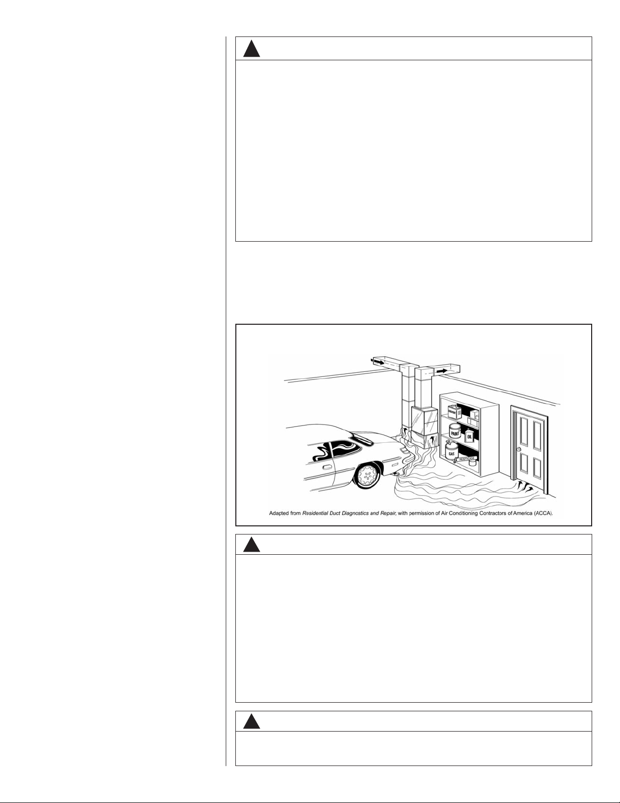
FIGURE 1
MIGRATION OF DANGEROUS SUBSTANCES, FUMES, AND ODORS INTO LIVING SPACES
WARNING
!
Duct leaks can create an unbalanced system and draw pollutants such as dirt,
dust, fumes and odors into the home causing property damage. Fumes and
odors from toxic, volatile or flammable chemicals, as well as automobile
exhaust and carbon monoxide (CO), can be drawn into the living space
through leaking ducts and unbalanced duct systems causing personal injury
or death (see Figure 1).
• If air-moving equipment or ductwork is located in garages or off-garage storage areas - all joints, seams, and openings in the equipment and duct must
be sealed to limit the migration of toxic fumes and odors including carbon
monoxide from migrating into the living space.
• If air-moving equipment or ductwork is located in spaces containing fuel
burning appliances such as water heaters or boilers - all joints, seams, and
openings in the equipment and duct must also be sealed to prevent depressurization of the space and possible migration of combustion byproducts
including carbon monoxide into the living space.
NOTICE
!
Improper installation, or installation not made in accordance with the Underwriters
Laboratory (UL) certification or these instructions, can result in unsatisfactory
operation and/or dangerous conditions and are not covered by the unit warranty.
5
important to have the proper balance between the air being supplied to each room and
the air returning to the cooling and heating equipment.
Proper balance and sealing of the duct system improves the efficiency of the heating
and air conditioning system and improves the indoor air quality of the home by reducing
the amount of airborne pollutants that enter homes from spaces where the ductwork
and/or equipment is located. The manufacturer and the U.S. Environmental Protection
Agency’s Energy Star Program recommend that central duct systems be checked by a
qualified contractor for proper balance and sealing.
NOTICE
!
In compliance with recognized codes, it is recommended that an auxiliary
drain pan be installed under all evaporator coils or units containing evaporator coils that are located in any area of a structure where damage to the
building or building contents may occur as a result of an overflow of the
coil drain pan or a stoppage in the primary condensate drain piping.
2.2 RECEIVING
Immediately upon receipt, all cartons and contents should be inspected for transit damage. Units with damaged cartons should be opened immediately. If damage is found, it
should be noted on the delivery papers, and a damage claim filed with the last carrier.
• After unit has been delivered to job site, remove carton taking care not to damage
unit.
• Check the unit rating plate for unit size, electric heat, coil, voltage, phase, etc. to be
sure equipment matches what is required for the job specification.
• Read the entire instructions before starting the installation.
• Some building codes require extra cabinet insulation and gasketing when unit is
installed in attic applications.
• If installed in an unconditioned space, apply caulking around the power wires, control
wires, refrigerant tubing and condensate line where they enter the cabinet. Seal the
power wires on the inside where they exit conduit opening. Caulking is required to
pre-vent air leakage into and condensate from forming inside the unit, control box,
and on electrical controls.
• Install the unit in such a way as to allow necessary access to the coil/filter rack and
blower/control compartment.
• Install the unit in a level position to ensure proper condensate drainage. Make sure
unit is level in both directions within 1/8”.
• Install the unit in accordance with any local code which may apply and the national
codes. Latest editions are available from: “National Fire Protection Association, Inc.,
Batterymarch Park, Quincy, MA 02269.” These publications are:
• ANSI/NFPA No. 70-(Latest Edition) National Electrical Code.
• NFPA90A Installation of Air Conditioning and Ventilating Systems.
• NFPA90B Installation of warm air heating and air conditioning systems.
• The equipment has been evaluated in accordance with the Code of Federal
Regulations, Chapter XX, Part 3280.
2.3 CLEARANCES
• All units are designed for “0” inches clearance to combustible material on all cabinet
surfaces.
• Units with electric heat require a one inch clearance to combustible material for the
first three feet of supply plenum and ductwork.
• All units require 24 inches minimum access to the front of the unit for service.
• These units may be installed in either ventilated or non-ventilated spaces.
6
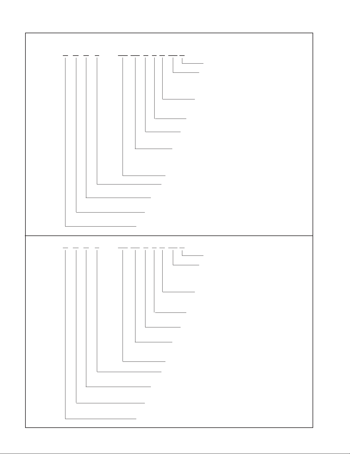
2.4 MODEL NUMBER EXPLANATION
FIGURE 2
MODEL NUMBER EXPLANATION
R H A L — FR 24 P J N 00 A
DESIGN VARIATION
ELECTRIC HEAT
00 = NO HEAT
05 = 5 kW
08 = 8 kW
10 = 10 kW
DISCONNECT CONFIGURATION
N = NONE
B = BREAKER
VOLTAGE
J = 208/240V/1/60
METERING
P = PISTON
T = TXV
CAPACITY
18 = 18,000 BTU/H
24 = 24,000 BTU/H
30 = 30,000 BTU/H
36 = 36,000 BTU/H
FR = FRONT RETURN
REFRIGERANT
L = 410A
FRONT RETURN/WALL MOUNT
A = PSC MOTOR - STANDARD EFFICIENCY
CLASSIFICATION
H = AIR HANDLER
TRADE BRAND
R H B L — FR 24 T J N 00 A
CAPACITY
24 = 18,000/24,000 BTU/H
36 = 30,000/36,000 BTU/H
FR = FRONT RETURN
REFRIGERANT
L = 410A
DESIGN VARIATION
ELECTRIC HEAT
00 = NO HEAT
05 = 5 kW
08 = 8 kW
10 = 10 kW
DISCONNECT CONFIGURATION
N = NONE
B = BREAKER
VOLTAGE
J = 208/240V/1/60
METERING
T = TXV
FRONT RETURN/WALL MOUNT
B = CONSTANT TORQUE MOTOR - HIGH EFFICIENCY
CLASSIFICATION
H = AIR HANDLER
TRADE BRAND
7
2.4A AVAILABLE MODELS
AVAILABLE MODELS AT J VOLTAGE
RHAL-FR18PJ
RHAL-FR24PJ
RHAL-FR30PJ
RHAL-FR36PJ
Notes:
• Supply circuit protective devices may be fuses or “HACR” type circuit breakers.
• Largest motor load is included in single circuit and multiple circuit 1.
• If non-standard fuse size is specified, use next size larger fuse size.
• J Voltage (208/240V) single phase air handler is designed to be used with single or
three phase 208/240V power. In the case of connecting 3-phase power to the air handler terminal block, bring only two leads to the terminal block. Cap, insulate and fully
secure the third lead.
• The air handlers are shipped from the factory with the proper indoor coil installed, and
cannot be ordered without a coil.
RHAL-FR36TJ
RHBL-FR24TJ
RHBL-FR36TJ
8
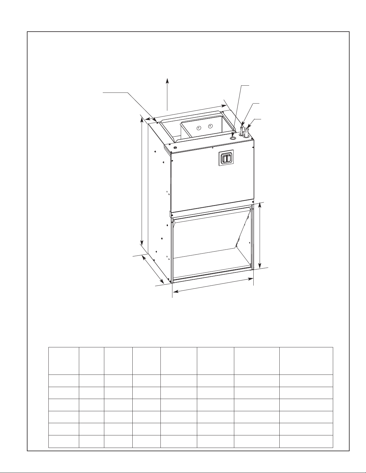
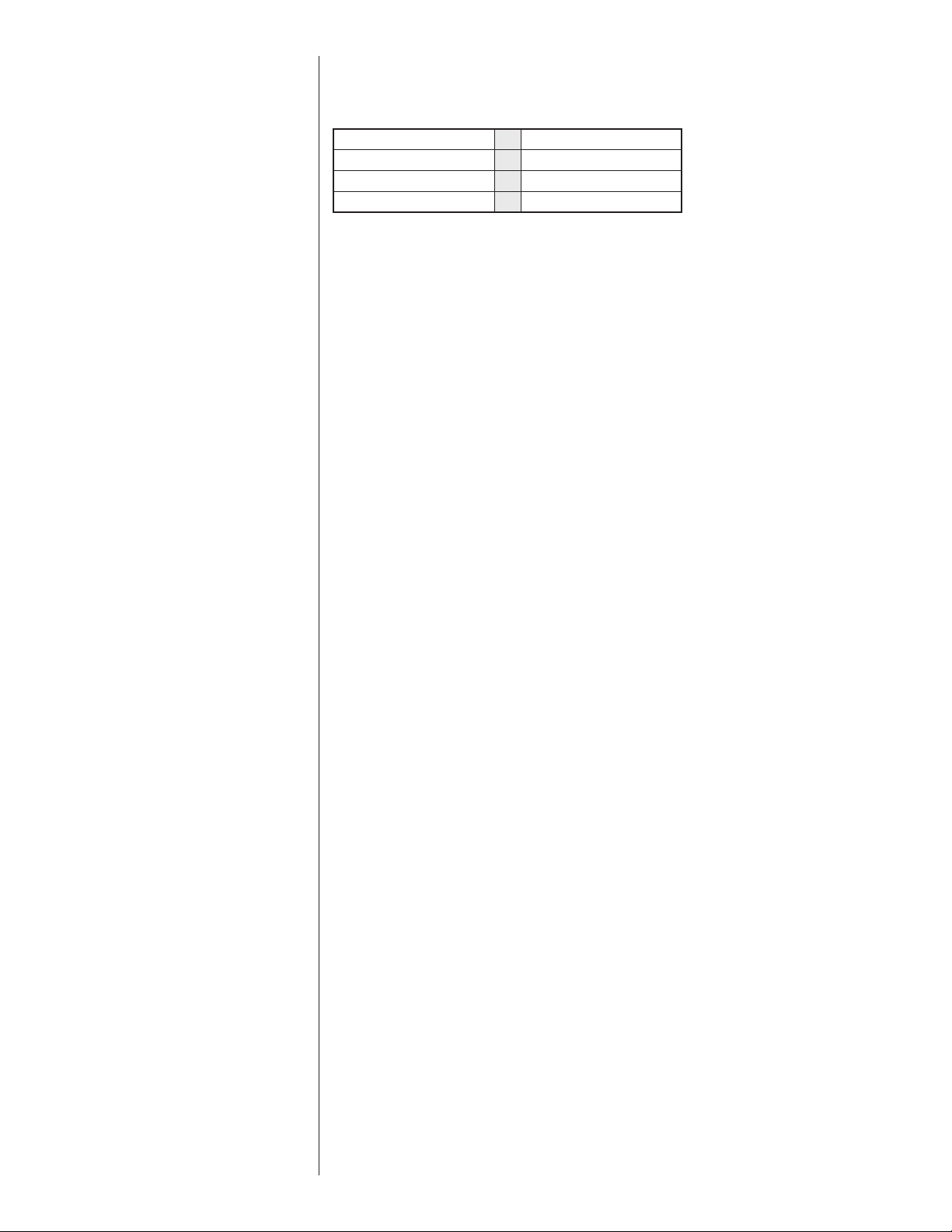
2.5 DIMENSIONS & WEIGHTS
FIGURE 3
DIMENSIONS AND WEIGHTS
FLANGES FOR FIELD
INSTALLED DUCTWORK
NOTE: 24" CLEARANCE REQUIRED
IN FRONT OF UNIT FOR FILTER
AND COIL MAINTENANCE.
HIGH VOLTAGE CONNECTION,
1-3/8” AND 7/8” KNOCKOUTS
SUPPLY AIR
A
LIQUID LINE CONNECTION
COPPER (SWEAT)
VAPOR LINE CONNECTION
COPPER (SWEAT)
B
DIMENSIONAL DATA
(A)
MODEL
RHAL-18
RHAL-24
RHAL-30
RHAL-36
RHBL-24
RHBL-36
UNIT
WIDTH
IN. [mm]
21-1/2
[546.1]
21-1/2
[546.1]
24
[609.6]
24
[609.6]
21-1/2
[546.1]
24
[609.6]
(B)
UNIT
HEIGHT
IN. [mm]
36
[914.4]
36
[914.4]
36
[914.4]
36
[914.4]
36
[914.4]
36
[914.4]
RETURN AIR
C
ALL UNITS ARE CONFIGURED FOR
VERTICAL UPFLOW. UNITS CANNOT
BE INSTALLED IN ANY OTHER CONFIGURATION.
(C)
UNIT
DEPTH
IN. [mm]
17
[431.8]
17
[431.8]
21
[533.4]
21
[533.4]
17
[431.8]
21
[533.4]
(D) RETURN
AIR OPENING
WIDTH IN.
[mm]
20
[508]
20
[508]
23
[584.2]
23
[584.2]
20
[508]
23
[584.2]
OPENING
(E)
RETURN AIR
OPENING
HEIGHT IN.
[mm]
17-7/16
[442.9]
17-7/16
[442.9]
21-3/8
[542.9]
21-3/8
[542.9]
17-7/16
[442.9]
21-3/8
[542.9]
E
D
FRONT RETURN SHOWN.
UNITS MAY ALSO BE INSTALLED
AS BOTTOM RETURN.
SEE THE APPLICATIONS SECTION
FOR MORE DETAIL.
AIRFLOW
COIL / [L/s]
600
[283]
800
[378]
1000
[472]
1200
[566]
600/800
[283/378]
1000/1200
[472/566]
UNIT WEIGHT /
SHIPPING WEIGHT
LBS. / [kg]
80/90
[36]/[41]
80/90
[36]/[41]
95/105
[43]/[48]
95/105
[43]/[48]
80/90
[36]/[41]
95/105
[43]/[48]
9
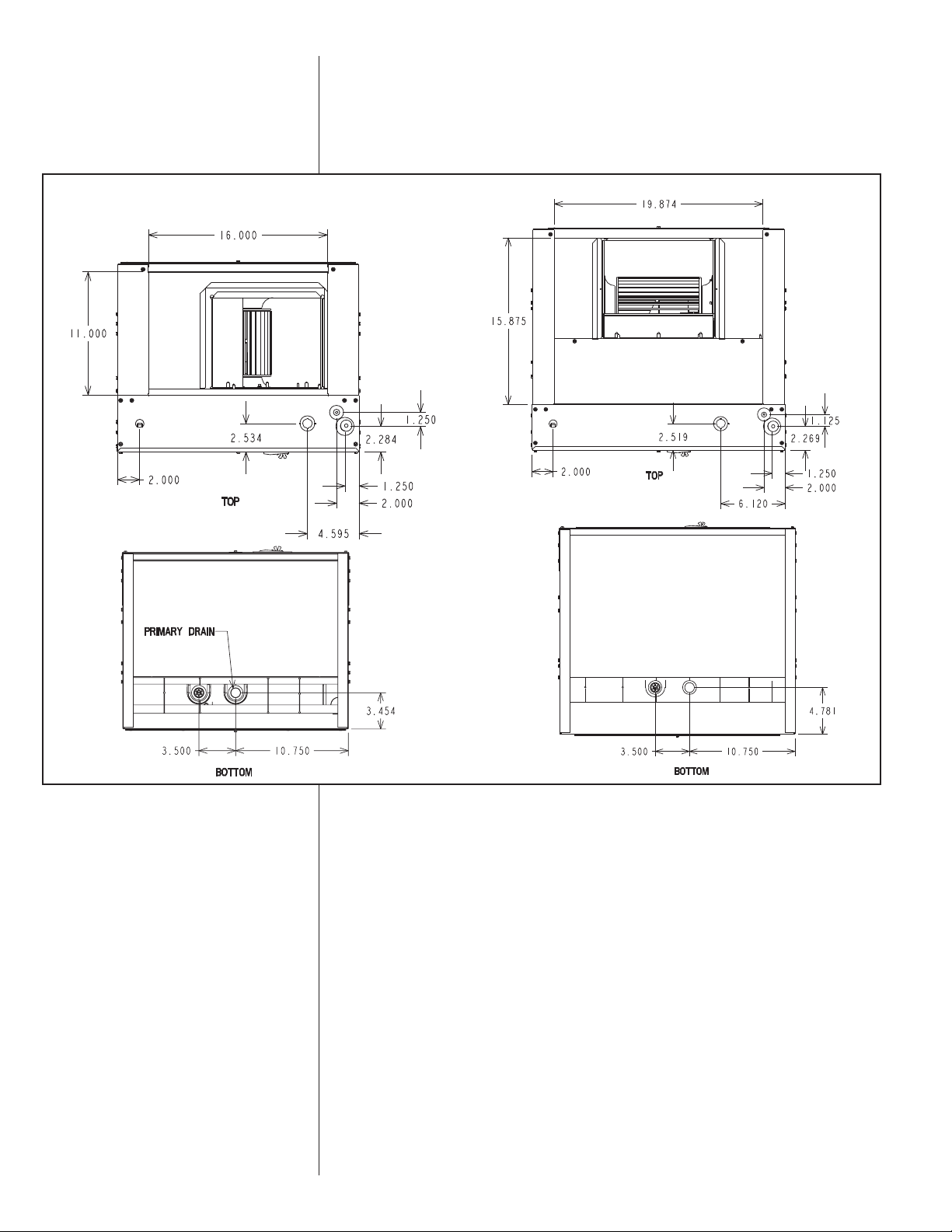
FIGURE 4
DIMENSIONS FOR DUCTWORK & DRAINS
3.0 APPLICATIONS
3.1 VERTICAL UPFLOW
• Vertical Upflow is the factory configuration for all models (see Figure 3).
• If return air is to be ducted, install duct flush with floor. Use fireproof resilient gasket 1/8
to 1/4 in. thick between duct, unit and floor. Set unit on floor over opening.
10
4.0 AIR HANDLER MOUNTING OPTIONS
The air handler comes standard with two different options for mounting, wall mount or
frame mount. Both mounting options require the unit to be level from side to side and
from front to back in order to allow condensate to properly drain from the unit. Failure to
do this will result in condensate to leak out from the unit potentially causing structural
damage to the surrounding support structures, dry wall, carpet, etc. around the unit.
Also, both mounting structures require the ability to accommodate a minimum of 150 lb.
load. Failure to do this will cause damage to the support structure and potentially damage the unit.
4.1 WALL MOUNT
The air handler comes standard with a wall mounting bracket and air handler mounting
bracket. Reference figure 5 for more detail.
1. Remove the wall mounting bracket from the back of the unit by removing one screw
which attaches the bracket to the air handler. Note: Discard the screw after you have
removed the wall mounting bracket.
2. Install bracket one the wall by using 6 wood screws (not provided). Make sure the
bracket is level in order to provided proper drainage from the unit. Note: Do not attach
the wall mounting bracket into unsupported dry wall. Make sure that the wood screws
are going into a structure that can support a minimum of 150 lb load.
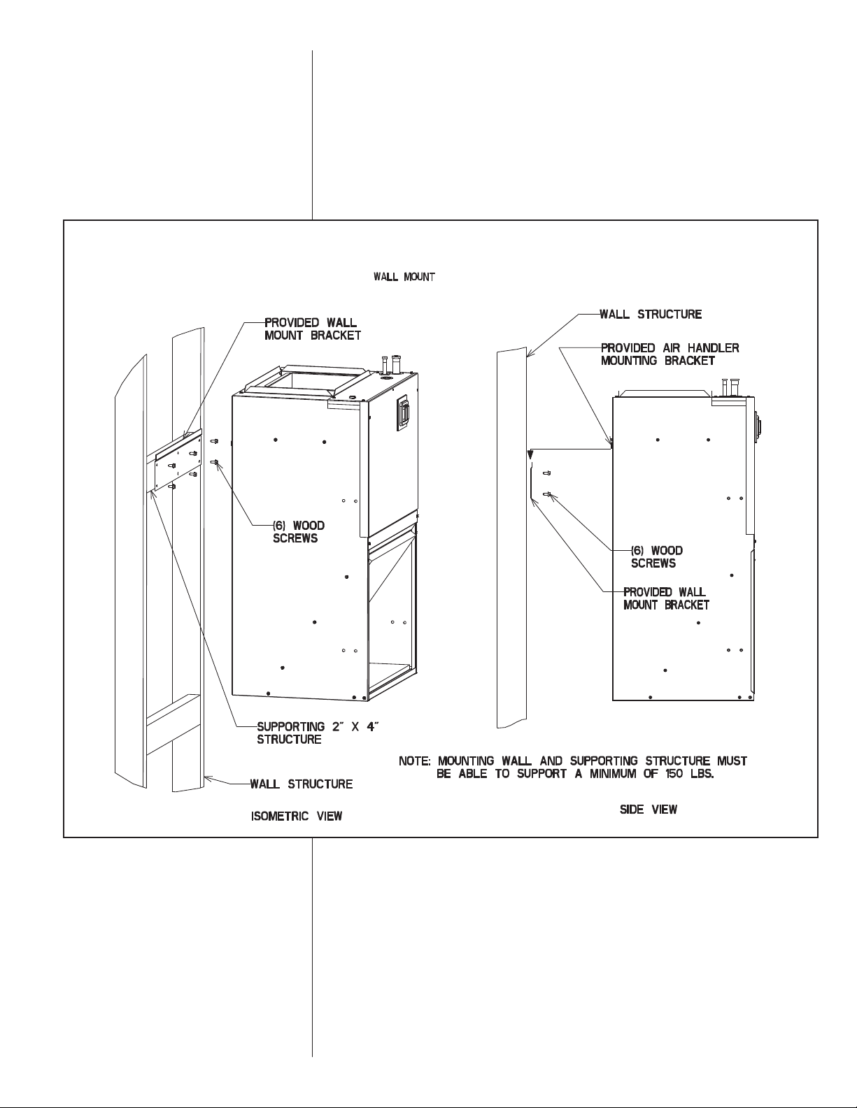
FIGURE 5
WALL MOUNT
3. Lift the air handler above the wall mounting bracket and attached the unit to the
installed bracket. Reference figure 5.
4.2 FRAME MOUNT
The air handler comes with 8 clearance holes 4 on each side. These holes are used to
mount the air handler inside of a frame structure (see figure 6). When mounting in this
fashion, make sure that the wood screws are mounted from within the air handler and
not outside of the unit. Installing the screws from the outside could cause damage to the
coil.
11
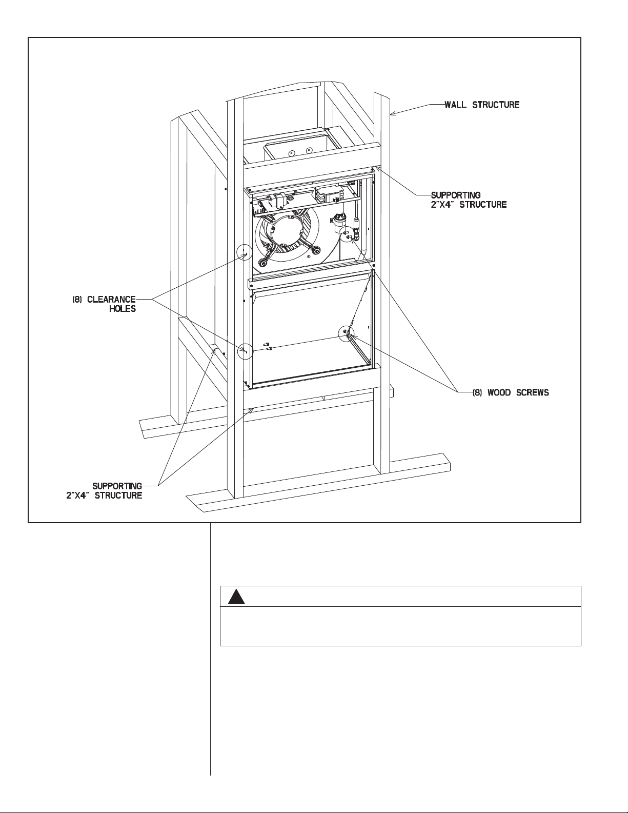
FIGURE 6
FRAME MOUNT
12
5.0 ELECTRICAL WIRING
Field wiring must comply with the National Electric Code (C.E.C. in Canada) and any
applicable local ordinance.
WARNING
!
Disconnect all power to unit before installing or servicing. More than one disconnect switch may be required to de-energize the equipment. Hazardous voltage can cause severe personal injury or death.
5.1 POWER WIRING
It is important that proper electrical power is available for connection to the unit model
being installed. See the unit nameplate, wiring diagram and electrical data in the installation instructions.
• If required, install a branch circuit disconnect of adequate size, located within sight of,
and readily accessible to the unit.
• IMPORTANT: After the Electric Heater is installed, units may be equipped with a circuit breaker. This circuit breaker protects the internal wiring in the event of a short circuit and serves as a disconnect. Circuit breakers installed within the unit do not pro-
 Loading...