

Rheem RH1T3617STANAA, RH1T4821MTANAA, RH1T3621MTANAA, RH1T4821STANAA, RH1T4824STANAA Installation Instructions Manual
...
WARNING
INSTALLATION INSTRUCTIONS
AIR HANDLERS
FEATURING INDUSTRY STANDARD R-410A REFRIGERANT:
(-)H1P Standard Efficiency with Aluminum Coil
(-)H1T High Efficiency with Aluminum Coil
!
sWARNING
These instructions are intended as an aid to qualified licensed
service personnel for pro per inst allation, adjustment and
operation of this unit. Read these instructions thoroughly before
attempting installation or operation. Failure to follow these
instructions may result in improper installation, adjustment,
service or maintenance possibly resulting in fire, electrical
shock, property damage, personal injury or death.
92-20521-110-00
(BASED ON 92-20521-66-09)

TABLE OF CONTENTS
!
!"#! $%&'()*+,&-./%(+-,*""""""""""""""""""""""""""""""""""""""""""""""""""""""""""""""""""""""""""""""*0*
1"#! 2','.%3*+,&-./%(+-,*"""""""""""""""""""""""""""""""""""""""""""""""""""""""""""""""""""""""""""*4*
"#$! %&'()*+ , *!%, -( )&+*.(,!/0(1*!2--.3.4, 35 !6 !%, 7( ( ) !/.)!81 + 9.*5!#################!:!
"#"! ;<43=.,>!?)(713*!@434.A47!######################################################################!B!
"#C! D(749!E1&04)!E(&4,39+*1)4!#################################################################!B!
"#F! /A+.9+094!D(749G!######################################################################################!H!
"#I! J.&4,G.(,G!6!K4.><*G!#############################################################################!L!
"#I#$! MNOP$?!##########################################################################################!L!
"#I#"! MNOP$Q!#########################################################################################!$R!
"#:! %&'()*+ , 34 !( -!?)( ' 4 )!%, 7 (( ) ST 1 * 7 (( ) !D + *3 <NU ' G!###############################!$$!
"#B! %&'()*+ , 34 !( -!+!81+9.*5!%,G*+99+*.(,!######################################################!$$!
5"#! +,$(%33%(+- , * """"""""""""""""""""""""""""""""""""""""""""""""""""""""""""""""""""""""""""""""""""""""*!1*
C#$! Q((9G!6!@4-).>4)+,*!################################################################################!$"!
C#$#$! Q((9G!@4V1.)47!-()!%,G*+99.,>!6!W4)A.3.,>!@NF$R/!D(749G!#########!$"!
C#$#"! W'43.-.3+*.(,G!(-!@NF$R/!############################################################!$"!
C#$#C! 81.3=!@4-4)4,34!X1.74!-()!@NF$R/!############################################!$"!
C#"! /''9.3+*.(,G!+,7!T).4,*+*.(,!#################################################################!$C!
C#"#$! Y4)*.3+9!U'-9(Z!6!P().[(,*+9!\4-*!J.G3<+)>4!#############################!$C!
C#"#"! Y4)*.3+9!J(Z,-9(Z!6!P().[(,*+9!@.><*!J.G3<+)>4!######################!$C!
C#"#C! %,G*+99+*.(,!.,!+,!U,3(, 7 .*.( , 47 !W ' +3 4!#####################################!$I!
C#"#F! %,G*+99+*.(,!.,!D(0.94SD + , 1 -+3 *1 )4 7!P ( &4G!############################!$:!
C#"#I! %,G*+99+*.(,!.,!;())(G.A4!2, A .)( , & 4 , *G!#####################################!$B!
C#C! /1].9.+)5!TA4)-9(Z!?+,!###########################################################################!$B!
C#F! ;94+)+,34G!##############################################################################################!$B!
C#I! J13*!^9+,>4G!###########################################################################################!$B!
C#:! J13*Z()=!################################################################################################!$H!
C#B! @4*1),!/.)!^.9*4)!######################################################################################!$H!
C#H! T).-.34!W.[4!##############################################################################################!$L!
C#L! @4-).>4)+,*!\.,4!;(,,43*.(,G!6!;<+)>.,>!##############################################!$L!
C#L#$! ?)4'+)+*.(,!################################################################################!$L!
C#L#"! \.V1.7!\.,4!^.9*4)!J).4)!###############################################################!$L!
C#L#C! _)+[.,>!#######################################################################################!$L!
C#L#F! \4+=!Q4G*.,>!###############################################################################!"R!
C#L#I! 2A+31+*.(,!#################################################################################!"R!
C#L#:! @4-).>4)+,*!;<+)>.,>!#################################################################!"R!
C#$R! Q`Y!W4,G.,>!_190!/**+3<&4,*!#############################################################!"R!
C#$$! ;(,74,G+*4!J)+.,!################################################################################!"R!
C#$"! Q<4)&(G*+*!##########################################################################################!""!
C#$C! 2943*).3+9!K.).,>
!############### # # # ############### # # # # ############### # # # ############### # # # # ########!""!
C#$C#$! ;(,-.>1).,>!U,.*!-()!"RH!Y(9*!?(Z4)!#########################################!""!
C#$C#"! X)(1,7.,>!##################################################################################!""!
C#$C#C! ?(Z 4)!K.).,>!#############################################################################!""!
C#$C#F! ;(''4)!K.)4!W.[4!#######################################################################!"C!
C#$C#I! 2943*).3+9!J+*+!a!_9(Z4)!D(*()!T,95!K.*<(1*!2943*).3!P4+*!#####!"C!
C#$C#I#$! MNOP$?!M?W;!D(*()O!##########################################################!"C!
C#$C#I#"! MNOP$Q!M;(,G*+,*!Q()V14!2;D!D ( *()O !#############################!"C!
C#$C#:! 2943*).3+9!J+*+!a!K.*<!2943*).3!P4+*!###########################################!"F!
C#$C#:#$! MNOP$?!M?W;!D(*()O!##########################################################!"I!
C#$C#:#"! MNOP$Q!M;(,G*+,*!Q()V14!2;D!D ( *()O !#############################!"B!
C#$C#B! 2943*).3!P4+*4)!b.*!W1''94&4,*+9!%,-()&+*.(,!##########################!CR!
C#$C#H! ;(,*)(9!K.).,>!###########################################################################!C$!
C#$C#L! Q<4)&(G*+*!6!;(,*)(9!K.).,>!;(,,43*.(,G!###############################!C$!
C#$F! /.)N^9(Z!###############################################################################################!C$!
C#$F#$! X4,4)+9!/.)N^9(Z!T'4)+*.,>!\.&.*G!############################################!C"!
!
2

TABLE OF CONTENTS (continued)
!
C#$F#"! W4943*.,>!%,7(()!_9(Z4)!D(*()!W'447!######################################!C"!
C#$F#"#$! MNOP$?!M?W;!D(*()O!##########################################################!C"!
C#$F#"#"! MNOP$Q!M;(,G*+,*!Q()V14!2;D!D ( *()O !#############################!C"!
C#$F#C! /.)N^9(Z!?4)-()&+,34!J+*+!#######################################################!CC!
C#$F#C#$! MNOP$?!M?W;!D(*()O!a!"FRY!##############################################!CC!
C#$F#C#"! MNOP$?!M?W;!D(*()O!a!$$IS"RHSFH RY !###############################!CI!
C#$F#C#C! MNOP$Q!M;(,G*+,*!Q()V14!2;D !D ( *()O!#############################!CB!
0"#! $(%.(678*""""""""""""""""""""""""""""""""""""""""""""""""""""""""""""""""""""""""""""""""""""""""""""""""*0!*
F#$! ?)4NW*+)*!;<43=9.G*!##################################################################################!F$!
F#"! W5G*4&!W*+)*NU'!+,7!T'4)+*.(,+9!;<43=NT1*!#########################################!F$!
F#C! W4V14,34!(-!T'4)+*.(,!##########################################################################!F$!
F#C#$! ;((9.,>!D(74!############################################################################!F$!
F#C#"! 2943*).3!P4+*!D(74!####################################################################!F$!
F#C#C! P4+*!?1&'!P4+*.,>!D(74!#########################################################!F"!
F#C#F! W1''94&4,*+9!2943*).3!P4+*!J1).,>!J4-)(G*!###############################!F"!
F#C#I! 2&4)>4,35!P4+*!MP4+*!?1&'O!###################################################!F"!
F#C#:! Q<4)&(G*+*!^+,!W4**.,>!#############################################################!F"!
F#F! ;())43*.,>!2943*).3!P4+*!=K!-()!Y(9*+>4!#################################################!F"!
F#I! ;+9319+*.,>!2943*).3!P4+*!;+'+3.*5!.,!_QUP!############################################!F"!
F#:! ;<43=.,>!%,7(()!/.)N^9(Z!#######################################################################!FC!
F#:#$! 2G*.&+*.,>!;^D!UG.,>!2]*4),+9!W*+*.3!?)4GG1)4!#########################!FC!
F#:#"! 2G*.&+*.,>!;^D!UG.,>!2943*).3!P4+*!Q4&'4)+*1)4!@.G4!#############!FC!
F#B! ;<43=.,>!@4-).>4)+,*!;<+)>4!##################################################################!FC!
9"#! :-/8-,',($*;*:-,(.-3$*"""""""""""""""""""""""""""""""""""""""""""""""""""""""""""""""""""*00*
I#$! _9(Z4)!D(*()!#########################################################################################!FF!
I#"! D(*()!@1,!;+'+3.*()!##############################################################################!FF!
I#C! _9(Z4)!;(,*)(9!#######################################################################################!FF!
I#F! _9(Z4)!####################################################################################################!FI!
I#I! Q)+,G-()&4)!###########################################################################################!FI!
I#:! %,7(()!; ( .9!/ GG 4&095!#############################################################################!FI!
4"#! %::'$$-.+'$*;*<+($*"""""""""""""""""""""""""""""""""""""""""""""""""""""""""""""""""""""""""""""""*04*
:#$! 2943*).3!@4G.G*+,34!P4+*4)!b.*G!###############################################################!F:!
:#"! c1&'4)!_+)!b.*G !######################################################################################!F:!
:#C! /1].9.+)5!P().[(,*+9!TA4)-9(Z!?+,G!########################################################!F:!
:#F! 2]*4),+9!^.9*4)!_+G4G!################################
###############################################!FB!
:#I! ;(&01G*.094!^9(()!_+G4G!########################################################################!FB!
:#:! P().[(,*+9!/7+'*4)!b.*G!##########################################################################!FB!
="#! /%+,(',%,:'*"""""""""""""""""""""""""""""""""""""""""""""""""""""""""""""""""""""""""""""""""""""""*0>*
B#$! /.)N^.9*4)!#################################################################################################!FH!
B#"! %,7(()!; ( .9d!J)+ ., !? +, d!J )+ ., !\., 4!##########################################################!FH!
B#C! _9(Z4)!D(*()!6!K<449!##########################################################################!FH!
B#F! D(*()!\10).3+*.(,!##################################################################################!FH!
B#I! _9(Z4)!/GG4&095!@4&(A+9!6!@4'9+34&4,*!###########################################!FH!
B#:! D(*()!@4'9+34&4,*!###############################################################################!FL!
B#B! _9(Z4)!K<449!@4'9+34&4,*!##################################################################!FL!
B#H! @4'9+34&4,*!?+)*G!#################################################################################!IR!
>"#! ?+%2,-$(+:$*""""""""""""""""""""""""""""""""""""""""""""""""""""""""""""""""""""""""""""""""""""""""""*9#*
@"#! A+.+,2*?+%2.%/$*""""""""""""""""""""""""""""""""""""""""""""""""""""""""""""""""""""""""""""""""*9!*
L#$! MNOP$?!a!$$IY !#########################################################################################!I$ !
L#"! MNOP$?!a!"RHS"F RY !##################################################################################!I"!
L#C! MNOP$?!a!FHRY !#########################################################################################!IC !
L#F! MNOP$Q!a!$$IY !#########################################################################################!IF!
L#I! MNOP$Q!a!"RHS"F RY !##################################################################################!II!
L#:! MNOP$Q!a!FHRY !#########################################################################################!I:!
3
SEE SECTION 4.0:
WARNING
!
Disc o n nect all pow e r to un i t
be f o r e i n stalling or servicing.
More than one disconnect switch
may be required to de-energize
the equipment. Hazardous voltage can cause severe personal
injury or death.
WARNING
!
If removal of the blower assembly is
required, all disconnect switches
supplying power to the equipment
must be de-energized and locked (if
no t in s ight o f unit ) so t h e fie l d
power wires can be safely removed
from the blower assembly. Failure
to do so can cause electrical shock
result i n g in perso n a l in j u r y or
death.
WARNING
!
Because of possible damage to
equipment or personal injury,
installation, service, and maintenance should be performed by a
trained, qualified service personnel. Consumer service is recommended only for filter cleaning/
replacement. Never operate the
unit wit h th e ac c e ss pane l s
removed.
(
LECTRICAL WIRING)
E
(SEE SECTION 12.5: BLOWER
ASSEMBLY REMOVAL &
EPLACEMENT)
R
1.0 SAFETY INFORMATION
WARNING
!
Duct leaks can create an unbalanced system and draw pollutants such as dirt,
dust, fumes and odors into the home causing property damage. Fumes and
odors from toxic, volatile or flammable chemicals, as well as automobile
exhaust and carbon monoxide (CO), can be drawn into the living space
through leaking ducts and unbalanced duct systems causing personal injury
or death (see Figure 1).
• If air-moving equipment or ductwork is located in garages or off-garage storage areas - all joints, seams, and openings in the equipment and duct must
be sealed to limit the migration of toxic fumes and odors including carbon
monoxide from migrating into the living space.
• If air-moving equipment or ductwork is located in spaces containing fuel
urning appliances such as water heaters or boilers - all joints, seams, and
b
openings in the equipment and duct must also be sealed to prevent depressurization of the space and possible migration of combustion byproducts
including carbon monoxide into the living space.
WARNING
!
These instructions are intended as an aid to qualified, licensed service personnel for proper installation, adjustment and operation of this unit. Read
these instructions thoroughly before attempting installation or operation.
Failure to follow these instructions may result in improper installation, adjustment, service or maintenance possibly resulting in fire, electrical shock, property damage, personal injury or death.
WARNING (SEE SECTION 3.2.2: VERTICAL DOWNFLOW)
!
The RXHB-17, RXHB-21 or RXHB-24 combustible floor base is required when
some units with electric heat are applied downflow on combustible flooring.
Failure to use the base can cause a fire resulting in property damage, personal
injury or death. See CLEARANCES
See the accessory section in this manual for combustible floor base RXHB.
for units requiring a combustible floor base.
WARNING (SEE SECTION 3.13.2: GROUNDING)
!
The unit must be permanently grounded. Failure to do so can result in electrical shock causing personal injury or death.
WARNING (SEE SECTION 7.0: MAINTENANCE)
!
Units with circuit breaker(s) meet requirements as a service disconnect
switch, however, if access is required to the line side (covered) of the circuit
breaker, this side of the breaker(s) will be energized with the breaker(s) deenergized. Contact with the line side can cause electrical shock resulting in
personal injury or death.
!
WARNING (SEE SECTION 3.6: DUCTWORK)
Do not, under any circumstances, connect return ductwork to any other heat
producing device such as fireplace insert, stove, etc. Unauthorized use of
such devices may result in fire, carbon monoxide poisoning, explosion, personal injury or property damage.
4
Continued on next page ❯
WARNING
!
PROPOSITION 65: This appliance contains fiberglass insulation.
Respirable particles of fiberglass
are known to the State of California
to cause cancer.
All manufacturer products meet current Federal OSHA Guidelines for
safety. California Proposition 65
arnings are required for certain
w
products, which are not covered by
the OSHA standards.
California's Proposition 65 requires
warnings for products sold in
California that contain or produce
any of over 600 listed chemicals
known to the State of California to
cause cancer or birth defects such
as fiberglass insulation, lead in
brass, and combustion products
from natural gas.
All “new equipment” shipped for
sale in California will have labels
stating that the product contains
and/or produces Proposition 65
chemicals. Although we have not
changed our processes, having the
same label on all our products facilitates manufacturing and shipping.
We cannot always know “when, or
if” products will be sold in the
California market.
You may receive inquiries from customers about chemicals found in, or
produced by, some of our heating
and air-conditioning equipment, or
found in natural gas used with
some of our products. Listed below
are those chemicals and substances commonly associated with
similar equipment in our industry
and other manufacturers.
• Glass Wool (Fiberglass) Insulation
• Carbon Monoxide (CO).
• Formaldehyde
• Benzene
More details are available at the
websites for OSHA (Occupational
Safety and Health Administration),
at www.osha.gov
California’s OEHHA (Office of
Environmental Health Hazard
Assessment), at www.oehha.org
Consumer education is important
since the chemicals and substances
on the list are found in our daily
lives. Most consumers are aware
that products present safety and
health risks, when improperly used,
handled and maintained.
and the State of
.
WARNING (SEE SECTION 3.7: AIR FILTER)
!
Do not operate the system without filters. A portion of the dust entrained in the
air may temporarily lodge in the duct runs and at the supply registers. Any circulated dust particles could be heated and charred by contact with the heating
elements. This residue could soil ceilings, walls, drapes, carpets and other
articles in the house.
Soot damage may occur even with filters in place when certain types of candles, oil lamps or standing pilots are burned.
WARNING
!
The first 36 inches of supply air plenum and ductwork must be constructed of
sheet metal as required by NFPA 90B. The supply air plenum or duct must
have a solid sheet metal bottom directly under the unit with no openings, registers or flexible air ducts located in it. If flexible supply air ducts are used they
may be located only in the vertical walls of a rectangular plenum, a minimum
of 6 inches from the solid bottom. Metal plenum or duct may be connected to
the combustible floor base, if not, it must be connected to the unit supply duct
flanges such that combustible floor or other combustible material is not
exposed to the supply air opening from the downflow unit. Exposing combustible (non-metal) material to the supply opening of a downflow unit can
cause a fire resulting in property damage, personal injury or death.
Exceptions to downflow warnings:
• Installations on concrete floor slab with supply air plenum and ductwork
completely encased in not less than 2 inches of concrete (See NFPA 90B).
CAUTION
!
Unit must be reconfigured for vertical down or horizontal right supply air discharge applications. The coil must be repositioned so the vertical drainpan is
on the bottom for vertical down discharge applications or the horizontal drip
pan is below coil for horizontal right discharge applications. Failure to reconfigure the unit for these applications can result in property damage and poor
system performance.
CAUTION (SEE SECTION 3.3: AUXILIARY OVERFLOW PAN)
!
In compliance with recognized codes, an auxiliary drain pan must be
installed under all equipment containing evaporator coils that are located in
any area of a structure where damage to the building or building contents
may occur as a result of an overflow of the coil drain pan or a stoppage in
the primary condensate drain piping. See Section 6.3 of this manual for
auxiliary horizontal overflow pan accessory information (model RXBM).
NOTICE
!
When used in cooling applications, excessive sweating may occur when unit
is installed in an unconditioned space. This can result in property damage.
NOTICE
!
Improper installation, or installation not made in accordance with the Underwriters
Laboratory (UL) certification or these instructions, can result in unsatisfactory
operation and/or dangerous conditions and are not covered by the unit warranty.
(SEE SECTION 3.2.2: VERTICAL DOWNFLOW & HORIZONTAL RIGHT DISCHARGE )
5
NOTICE
!
Use of this air-handler during construction is not recommended. If operation during construction is absolutely required, the following temporary
installation requirements must be followed:
Installation must comply with all Installation Instructions in this manual
including the following items:
• Properly sized power supply and circuit breaker/fuse
• Air-handler operating under thermostatic control;
• Return air duct sealed to the air-handler;
• Air filters must be in place;
• Correct air-flow setting for application
• Removing the coil and storing it in a clean safe place is highly recommended until construction is completed and the outdoor unit is installed.
• Clean air-handler, duct work, and components including coil upon completion of the construction process and verify proper air-handler operating conditions according as stated in this instruction manual.
• NOTE: Electric strip heater elements tend to emit a burning odor for a few
days if dust has accumulated during construction. Heater elements are
easily damaged. Take great care when cleaning them. Low pressure compressed air is recommended for cleaning elements.
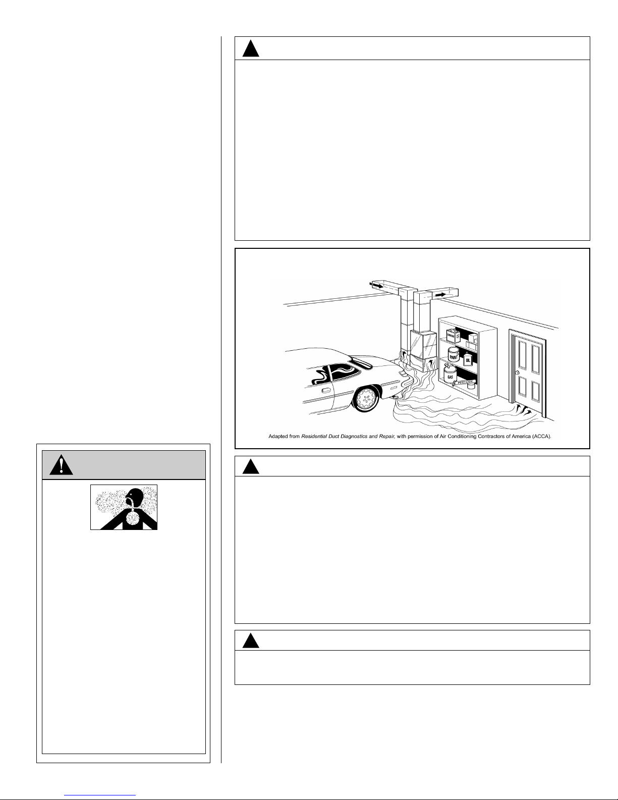
FIGURE 1
MIGRATION OF DANGEROUS SUBSTANCES, FUMES, AND ODORS INTO LIVING SPACES
WARNING
Carbon Monoxide (CO) Poisoning
Can Cause Severe Injury or Death.
Carbon Monoxide from the exhaust of motor
vehicles and other fuel burning devices can be drawn
into the living space by the operation of the central
heating and air conditioning system.
Exhaust from motor vehicles, generators, garden
tractors, mowers, portable heaters, charcoal and gas grills,
gasoline powered tools, and outdoor camping equipment
contains carbon monoxide, a poisonous
gas that can kill you. You cannot see it, smell it, or taste it.
•
Do NOT operate an automobile or any engine in a
garage for more than the few seconds it takes to
enter or exit the garage.
•
Do NOT operate any fuel-burning device in an
enclosed or partly enclosed space, or near
building windows, doors or air intakes.
The U.S. Consumer Product Safety Commission (CPSC)
and Health Canada recommend the installation of UL or CSA
certified Carbon Monoxide Alarm(s) in every home.
WARNING
!
Duct leaks can create an unbalanced system and draw pollutants such as dirt,
dust, fumes and odors into the home causing property damage. Fumes and
odors from toxic, volatile or flammable chemicals, as well as automobile
exhaust and carbon monoxide (CO), can be drawn into the living space
through leaking ducts and unbalanced duct systems causing personal injury
or death (see Figure 1).
• If air-moving equipment or ductwork is located in garages or off-garage storage areas - all joints, seams, and openings in the equipment and duct must
be sealed to limit the migration of toxic fumes and odors including carbon
monoxide from migrating into the living space.
• If air-moving equipment or ductwork is located in spaces containing fuel
burning appliances such as water heaters or boilers - all joints, seams, and
openings in the equipment and duct must also be sealed to prevent depressurization of the space and possible migration of combustion byproducts
including carbon monoxide into the living space.
NOTICE
!
Improper installation, or installation not made in accordance with the Underwriters
Laboratory (UL) certification or these instructions, can result in unsatisfactory
operation and/or dangerous conditions and are not covered by the unit warranty.
2.0 GENERAL INFORMATION
2.1 IMPORTANT INFORMATION ABOUT EFFICIENCY & INDOOR
AIR QUALITY
Central cooling and heating equipment is only as efficient as the duct system that carries the cooled or heated air. To maintain efficiency, comfort and good indoor air quality,
6
it is important to have the proper balance between the air being supplied to each room
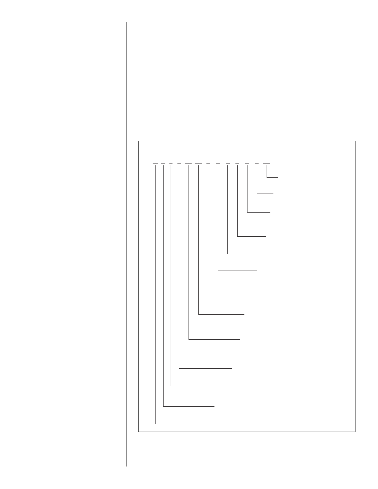
(-) H 1 T 24 17 S T A N A A ***
O
PTION CODE
BLANK = NONE
MINOR SERIES
A = FIRST
VOLTAGE
A = 115/1/60
D = 480/3/60
J = 208/240/1/60
NOMINAL CAPACITY
18 = 18,000 BTU/H
24 = 24,000 BTU/H*
30 = 30,000 BTU/H
36 = 36,000 BTU/H*
42 = 42,000 BTU/H
48 = 48,000 BTU/H*
60 = 60,000 BTU/H
MOTOR TYPE
P = PSC
T = CONSTANT TORQUE
STAGES OF AIR FLOW
1 = SINGLE
PRODUCT CATEGORY
H = AIR HANDLER
CONTROLS
N = NON-COMMUNICATING
MAJOR SERIES
A = FIRST DESIGN
B = SECOND DESIGN
METERING DEVICE
T = TXV
P = PISTON
COIL EFFICIENCY
S = STANDARD
M = MEDIUM
H = HIGH
WIDTH
17 = 17.5” (600-1200 CFM)
21 = 21” (800-1600 CFM)
24 = 24.5 (1400-1800 CFM)
BRAND
24 = 18,000-24,000 BTU/H
36 = 30,000-36,000 BTU/H
48 = 42,000-48,000 BTU/H
*(-)H1T ONLY
and the air returning to the cooling and heating equipment.
Proper balance and sealing of the duct system improves the efficiency of the heating
and air conditioning system and improves the indoor air quality of the home by reducing
the amount of airborne pollutants that enter homes from spaces where the ductwork
and/or equipment is located. The manufacturer and the U.S. Environmental Protection
Agency’s Energy Star Program recommend that central duct systems be checked by a
qualified contractor for proper balance and sealing.
2.2 CHECKING PRODUCT RECEIVED
Immediately upon receipt, all cartons and contents should be inspected for transit damage.
Units with damaged cartons should be opened immediately. If damage is found, it should
be noted on the delivery documents and a damage claim filed with the delivering carrier.
After unit has been delivered to the job site, remove the unit from the carton taking care
not to damage the unit. Check the unit rating plate for unit model number, unit size, coil
model, voltage, phase, etc. to assure the unit matches the job specifications.
2.3 MODEL NUMBER NOMENCLATURE
FIGURE 2
MODEL NUMBER NOMENCLATURE
7
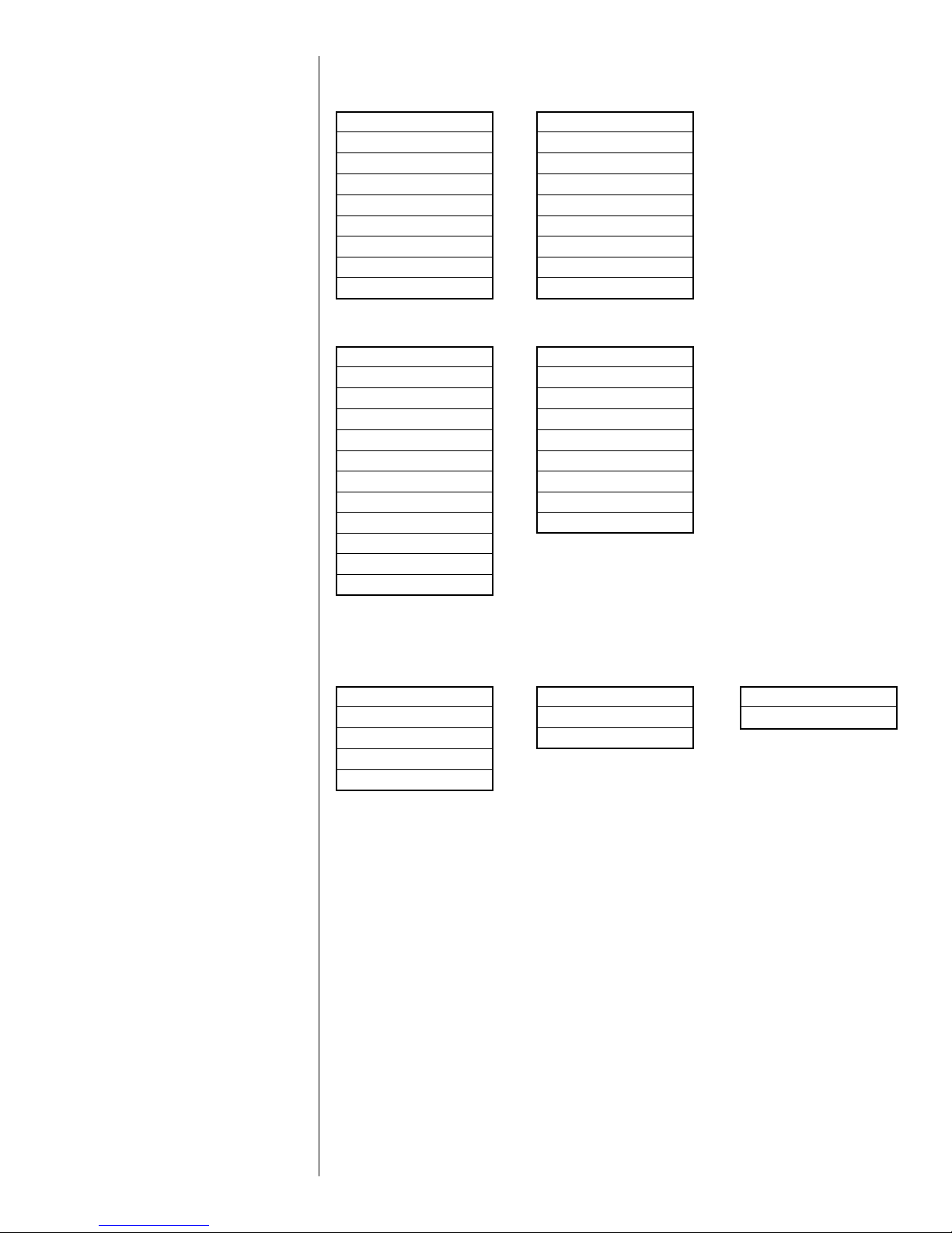
2.4 AVAILABLE MODELS
AVAILABLE 115V MODELS
(-)H1T2417STANAA
(-)H1T3617STANAA
(-)H1T3621MTANAA
(-)H1T3621HTANAA
(-)H1T4821STANAA
-)H1T4821MTANAA
(
(-)H1T4824STANAA
(-)H1T6021STANAA
(-)H1T6024STANAA
AVAILABLE 208/240V MODELS
(-)H1T2417STANJA
(-)H1T3617STANJA
(-)H1T3621MTANJA
(-)H1T3621HTANJA
(-)H1T4821STANJA
(-)H1T4821MTANJA
(-)H1T4824STANJA
(-)H1T6021STANJA
(-)H1T6024STANJA
(-)H1T4821SPBNJA
(-)H1T2417SPBNJA
(-)H1T3617SPBNJA
(-)H1T2417SPBNAA
(-)H1T3617SPBNAA
(-)H1T4821SPBNAA
(-)H1P1817STANAA
(-)H1P2417STANAA
-)H1P3017STANAA
(
(-)H1P3617STANAA
(-)H1P4221STANAA
(-)H1P4821STANAA
(-)H1P1817STANJA
(-)H1P2417STANJA
(-)H1P3017STANJA
(-)H1P3617STANJA
(-)H1P3621STANJA
(-)H1P4221STANJA
(-)H1P4821STANJA
(-)H1P4824STANJA
(-)H1P6024STANJA
AVAILABLE 480V MODELS
(-)H1T3617STANDA
(-)H1T4821STANDA
(-)H1T4824STANDA
(-)H1T6021STANDA
(-)H1T6024STANDA
Notes:
• J Voltage (208/240V) single phase air handler is designed to be used with single or
three phase 208/240V power. When connecting 3-phase power to the air handler terminal block, bring only two leads to the terminal block. Cap, insulate and fully secure
the third lead.
• The air handlers are shipped from the factory with the proper indoor coil installed, and
cannot be ordered without a coil.
• These air handlers do not have an internal filter rack. An external filter rack or other
means of filtration of return air is required.
• Electric resistance heaters are field installed items. (See Section 6.1)
(-)H1P3617STANDA
(-)H1P4221STANDA
(-)H1P4821STANDA
(-)H1P4824STANDA
(-)H1P6024STANDA
8
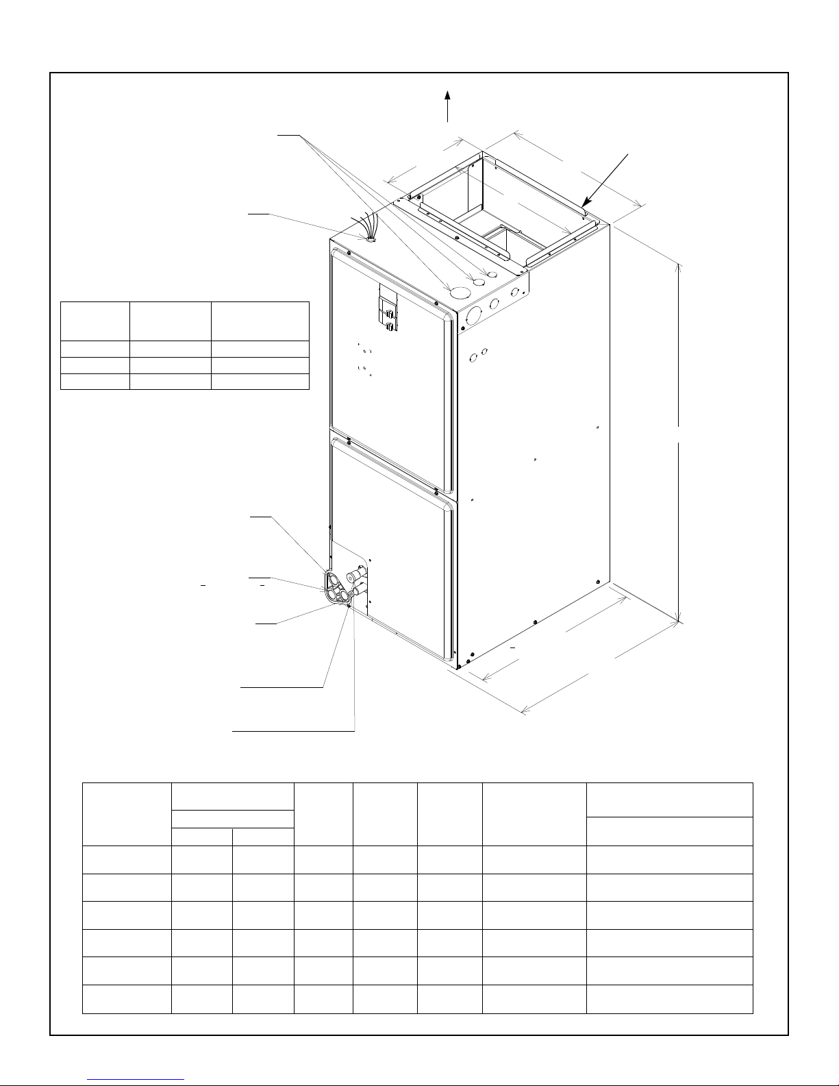
2.5.1 DIMENSIONS & WEIGHTS: (-)H1P MODELS
IGURE 3A
F
DIMENSIONS AND WEIGHTS
ELECTRICAL CONNECTIONS MAY EXIT TOP OR EITHER SIDE
HIGH VOLTAGE CONNECTION 7/8",
3/32", 1 31/32" DIA. KNOCK OUTS.
1
OW VOLTAGE CONNECTION
L
5/8" AND 7/8" KNOCK OUT
OUTSIDE OF CABINET)
(
Return Air Opening Dimensions
Return Air Return Air Opening
Model
Cabinet Size
17 157⁄8 193⁄4
21 193⁄8 193⁄4
24 227⁄8 193⁄4
Opening Width Depth/Length
(Inches) (Inches)
SUPPLY AIR
105/1
NOTE: 24" CLEARANCE REQUIRED
IN FRONT OF UNIT FOR FILTER
AND COIL MAINTENANCE.
LANGES ARE PROVIDED
6
W
A
F
FOR FIELD INSTALLATION
SEE DUCT FLANGES,
(
SECTION 3.5, FOR
NSTRUCTIONS)
I
H
AUXILIARY DRAIN CONNECTION
3/4" FEMALE PIPE THREAD (NPT)
HORIZONTAL APPLICATION ONLY
PRIMARY DRAIN CONNECTION
3/4" FEMALE PIPE THREAD (NPT)
AUXILIARY DRAIN CONNECTION
3/4" FEMALE PIPE THREAD (NPT)
UPFLOW/DOWNFLOW APPLICATION
ONLY
LIQUID LINE CONNECTION
COPPER (SWEAT)
VAPOR LINE CONNECTION
COPPER (SWEAT)
DIMENSIONAL DATA
REFRIGERANT
MODEL
SIZE
(-)H1P
1817S/2417S
3017S/3617S
3621S
4221S/4821S
4824S
6024S
CONNECTIONS
SWEAT (IN.) [MM] ID
LIQUID VAPOR
3
/8"
[9.53]
3
/8"
[9.53]
3
/8"
[9.53]
3
/8"
[9.53]
3
/8"
[9.53]
3
/8"
[9.53]
3
/4"
[19.05]
3
/4"
[19.05]
7
/8"
[22.23]
7
/8"
[22.23]
7
/8"
[22.23]
7
/8"
[22.23]
UNIT
HEIGHT
IN. [mm]
421/2"
[1080]
1
/2"
42
[1080]
1
42
/2"
[1080]
1
50
/2"
[1283]
1
/2"
50
[1283]
1
55
/2"
[1410]
191/2
RETURN AIR OPENING
UPFLOW UNIT SHOWN;
UNIT MAY BE INSTALLED UPFLOW, DOWNFLOW.
HORIZONTAL RIGHT, OR LEFT AIR SUPPLY.
UNIT
WIDTH
“W” IN.
[mm]
1
17
[444.5]
1
17
[444.5]
21"
[533.4]
21"
[533.4]
1
24
[622.3]
1
24
[622.3]
/2"
/2"
/2"
/2"
SUPPLY
DUCT
“A” IN.
[mm]
16"
[406.4]
16"
[406.4]
191/2"
[495.3]
1
/2"
19
[495.3]
23"
[584.2]
23"
[584.2]
NOMINAL
CFM
[L/s]
600/800
[283/378]
1000/1200
[472/566]
1200
[566]
1400/1600
[661/755]
1600
[755]
1800
[850]
2111/16
A-1038-01
UNIT WEIGHT / SHIPPING
WEIGHT (LBS.) [kg]
UNIT WITH
COIL (MAX. kW.)
81/95
[37/43]
90/104
[41/47]
109/124
[49/56]
130/146
[59/66]
143/161
[65/73]
164/181
[75/82]
9
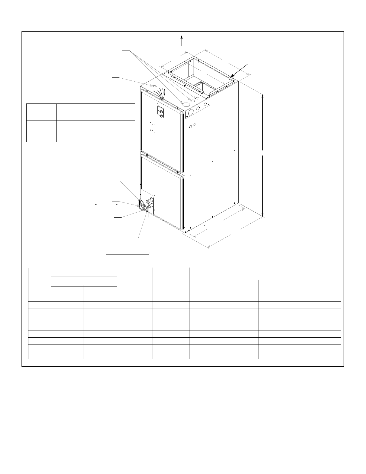
2.5.2 DIMENSIONS & WEIGHTS: (-)H1T MODELS
IGURE 3B
F
DIMENSIONS AND WEIGHTS
HIGH VOLTAGE CONNECTION 7/8",
3/32", 1 31/32" DIA. KNOCK OUTS.
1
LECTRICAL CONNECTIONS MAY
E
EXIT TOP OR EITHER SIDE
OW VOLTAGE CONNECTION
L
/8" AND 7/8" KNOCK OUT
5
(OUTSIDE OF CABINET)
Return Air Opening Dimensions
Return Air Return Air Opening
Model
Cabinet Size
17 157⁄8 193⁄4
21 193⁄8 193⁄4
24 227⁄8 193⁄4
Opening Width Depth/Length
(Inches) (Inches)
UXILIARY DRAIN CONNECTION
A
3/4" FEMALE PIPE THREAD (NPT)
ORIZONTAL APPLICATION ONLY
H
RIMARY DRAIN CONNECTION
P
3/4" FEMALE PIPE THREAD (NPT)
SUPPLY AIR
105/1
NOTE: 24" CLEARANCE REQUIRED
IN FRONT OF UNIT FOR FILTER
AND COIL MAINTENANCE.
6
A
W
LANGES ARE PROVIDED
F
FOR FIELD INSTALLATION
SEE DUCT FLANGES, SECTION 3.5,
(
FOR INSTRUCTIONS)
H
AUXILIARY DRAIN CONNECTION
3/4" FEMALE PIPE THREAD (NPT)
UPFLOW/DOWNFLOW APPLICATION
ONLY
LIQUID LINE CONNECTION
COPPER (SWEAT)
VAPOR LINE CONNECTION
COPPER (SWEAT)
UPFLOW UNIT SHOWN;
UNIT MAY BE INSTALLED UPFLOW, DOWNFLOW. HORIZONTAL RIGHT, OR LEFT AIR SUPPLY.
191/2
RETURN AIR
OPENING
2111/16
A-1038-01
DIMENSIONAL DATA
MODEL
SIZE
(-)H1T
REFRIGERANT CONNECTIONS
SWEAT (IN.) [mm] ID
LIQUID
VAPOR
UNIT
HEIGHT
IN. [mm]
UNIT
WIDTH
“W” IN.
[mm]
SUPPLY
DUCT
“A” IN.
[mm]
NOMINAL CFM
[L/s]
LO HI
2417S 3/8" [9.53] 3/4" [19.05] 421/2" [1080] 171/2" [445] 16" [409] 600 [283] 800 [378] 92/106 [42/48]
3617S 3/8" [9.53] 3/4" [19.05] 421/2" [1080] 171/2" [445] 16" [409] 1000 [472] 1200 [566] 96/110 [44/50]
3621M 3/8" [9.53] 7/8" [22.23] 501/2" [1282] 21" [533] 191/2" [495] 1000 [472] 1200 [566] 126/142 [57/64]
3621H 3/8" [9.53] 7/8" [22.23] 57 [1448] 21" [533] 191/2" [495] 1000 [472] 1200 [566] 137/149 [62/68]
4821S 3/8" [9.53] 7/8" [22.23] 501/2" [1282] 21" [533] 191/2" [495] 1400 [661] 1600 [755] 128/144 [56/65]
4821M 3/8" [9.53] 7/8" [22.23] 57 [1448] 21" [533] 191/2" [495] 1400 [661] 1600 [755] 139/151 [63/68]
4824S 3/8" [9.53] 7/8" [22.23] 501/2" [1282] 241/2" [622] 23" [585] 1600 [755] — 142/160 [64/72]
6021S 3/8" [9.53] 7/8" [22.23] 57 [1448] 21" [533] 191/2" [495] 1600 [755] 1725 [814] 139/151 [63/68]
6024S 3/8" [9.53] 7/8" [22.23] 551/2" [1410] 241/2" [622] 23" [585] — 1800 [850] 159/176 [72/80]
UNIT WEIGHT / SHIPPING
WEIGHT (LBS.) [kg]
UNIT WITH
COIL (MAX. kW.)
10

2.6 IMPORTANCE OF PROPER INDOOR/OUTDOOR MATCH-UPS
To assure many years of reliable operation and optimum customer comfort and to assure
the outdoor unit warranty remains valid, an air-handler model should be selected that is
properly matched to the outdoor unit. This is especially critical for heat pump systems
to assure proper refrigerant charge balance between the cooling and heating modes.
The recommended approach is to select an air-handler model that has an AHRI match
with the outdoor unit. Refer to the AHRI directory at www.ahridirectory.org to confirm
the air-handler and outdoor unit are a certified combination in the AHRI Directory.
2.7 IMPORTANCE OF QUALITY INSTALLATION
A quality installation is critical to assure safety, reliability, comfort, and customer satisfaction. Strict adherence to applicable codes, the information in this installation manual, the
outdoor unit installation manual, and the thermostat installation manual are key to a
quality installation. Read the entire instruction manuals before starting the installation.
IMPORTANT: This product has been designed and manufactured to meet certified AHRI
capacity and efficiency ratings with the appropriate outdoor units. However, proper
refrigerant charge, proper airflow, and refrigerant line sizing are critical to achieve optimum capacity and efficiency and to assure reliable operation. Installation of this product should follow the manufacturer’s refrigerant charging and airflow instructions located
in the outdoor unit installation instructions and the charging chart label affixed to the outdoor unit. Failure to confirm proper charge and airflow may reduce energy efficiency
and shorten equipment life.
Th e equi p m e n t h as been eval u a t e d in accordance w i t h t he Code of F e d e r a l
Regulations, Chapter XX, Part 3280.
Install the unit in accordance with applicable national, state, and local codes. Latest editions are available from: “National Fire Protection Association, Inc., Batterymarch Park,
Quincy, MA 02269.” These publications are:
• ANSI/NFPA No. 70-(Latest Edition) National Electrical Code.
• NFPA90A Installation of Air Conditioning and Ventilating Systems.
• NFPA90B Installation of warm air heating and air conditioning systems.
Install the unit in such a way as to allow necessary access to the coil/filter rack and
blower/control compartment.
11
3.0 INSTALLATION
Ambient and Tube
Thermometers
M
anifold
G
auge
S
et
B
razing
R
ods
T
orch Nitrogen
R
eclaimer
Recovery
Cylinders
A
llen Wrench
C
rescent Wrench
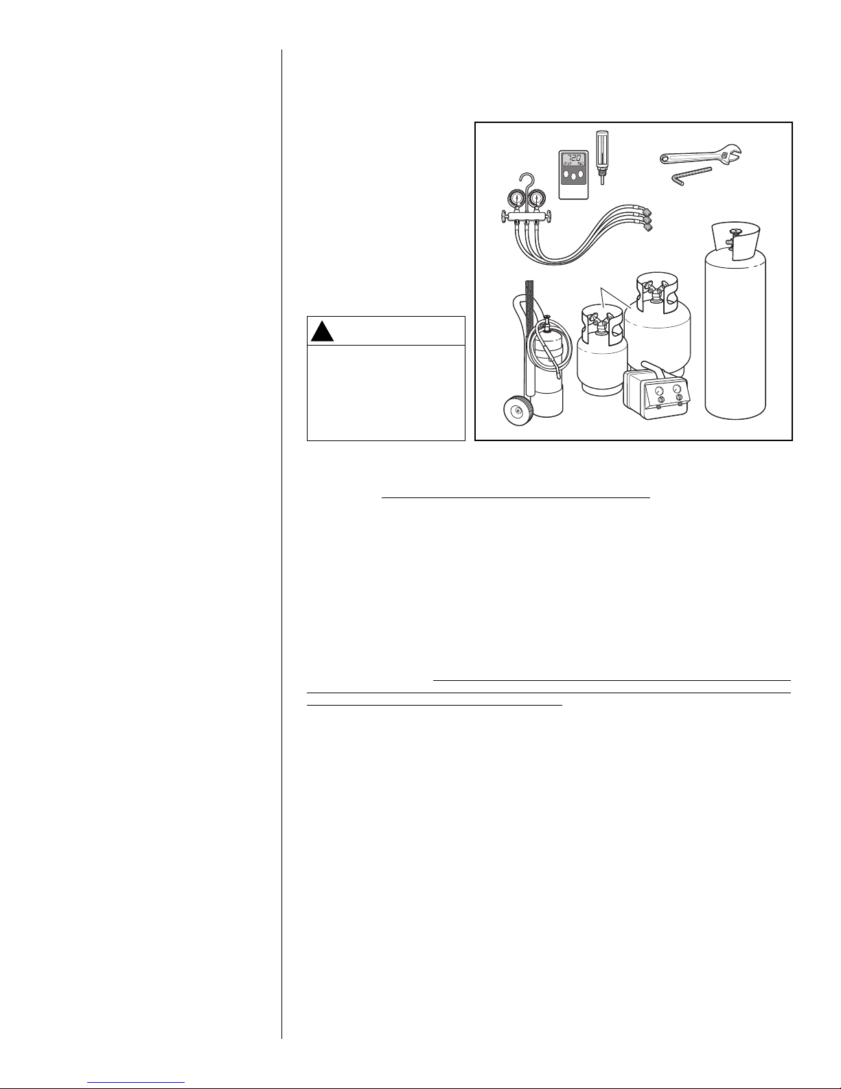
3.1 TOOLS & REFRIGERANT
3.1.1 TOOLS REQUIRED FOR INSTALLING AND SERVICING R-410A MODELS
Manifold Sets:
• Up to 800 PSIG High-Side
• Up to 250 PSIG Low-Side
• 550 PSIG Low-Side Retard
Manifold Hoses:
• Service Pressure Rating of
800 PSIG
Recovery Cylinders:
• 400 PSIG Pressure Rating
• Dept. of Transportation
4BA400 or BW400
NOTICE
!
R-410A systems operate
at h igher pr e ssur e s
than R-22 systems. Do
not use R- 2 2 s e rvic e
equ i p m e n t o r c o m p onents on R-410A equipment.
3.1.2 SPECIFICATIONS OF R-410A
Application: R-410A is not a drop-in replacement for R-22. Equipment designs must
accommodate its higher pressures. It cannot be retrofitted into R-22 heat pumps.
Physical Properties: R-410A has an atmospheric boiling point of -62.9°F [-52.7°C] and
its saturation pressure at 77°F [25°C] is 224.5 psig.
Composition: R-410A is a near-azeotropic mixture of 50% by weight difluoromethane
(HFC-32) and 50% by weight pentafluoroethane (HFC-125).
Pressure: The pressure of R-410A is approximately 60% (1.6 times) greater than R-
22. Recovery and recycle equipment, pumps, hoses, and the like must have design
pressure ratings appropriate for R-410A. Manifold sets need to range up to 800 psig
high-side and 250 psig low-side with a 550 psig low-side retard. Hoses need to have a
service pressure rating of 800 psig. Recovery cylinders need to have a 400 psig service
pressure rating, DOT 4BA400 or DOT BW400.
Combustibility: At pressures above 1 atmosphere, a mixture of R-410A and air can
become combustible. R-410A and air should never be mixed in tanks or supply
lines or be allowed to accumulate in storage tanks. Leak checking should never
be done with a mixture of R-410A and air. Leak-checking can be performed safely
with nitrogen or a mixture of R-410A and nitrogen.
3.1.3 QUICK-REFERENCE GUIDE FOR R-410A
• R-410A refrigerant operates at approximately 60% higher pressure (1.6 times) than
R-22. Ensure that servicing equipment is designed to operate with R-410A.
• R-410A refrigerant cylinders are light rose in color.
• R-410A, as with other HFCs, is only compatible with POE oils.
• Vacuum pumps will not remove moisture from POE oil used in R-410A systems.
• R-410A systems are to be charged with liquid refrigerants. Prior to March 1999, R-
410A refrigerant cylinders had a dip tube. These cylinders should be kept upright for
equipment charging. Post-March 1999 cylinders do not have a dip tube and should be
inverted to ensure liquid charging of the equipment.
• Do not install a suction line filter drier in the liquid line.
• A factory-approved outdoor liquid line filter drier is shipped with every unit and must
be installed in the liquid line at the time of installation. If only the air-handler is being
replaced on an existing system, the existing filter drier must be replaced at the time of
installation with a field supplied filter drier. IMPORTANT: A bi-flow filter drier must be
used for heat pump applications. Filter driers must be rated for minimum working
pressure of 600 psig. The filter drier will only have adequate moisture-holding capacity if the system is properly evacuated.
• Desiccant (drying agent) must be compatible for POE oils and R-410A refrigerant.
12
3.2 APPLICATIONS AND ORIENTATION
3.2.1 VERTICAL UPFLOW & HORIZONTAL LEFT DISCHARGE
• Vertical Upflow & Horizontal Left Discharge is the factory configuration for all models
(see Figure 4).
• The return air plenum must be large enough to supply unit and strong enough to sup-
port unit weight.
• If return air is to be ducted through the floor, install duct flush with floor. Use fireproof
resilient gasket 1/8 to 1/4 in. thick between duct, unit and floor. Set unit on floor over
opening.
IMPORTANT: Do not cut the side out of air-handler cabinet for a side return duct as this
will result in the return air bypassing the coil. Instead, install air-handler on top of a field
upplied sheet metal or wooden box and run the side return duct into the side of the box.
s
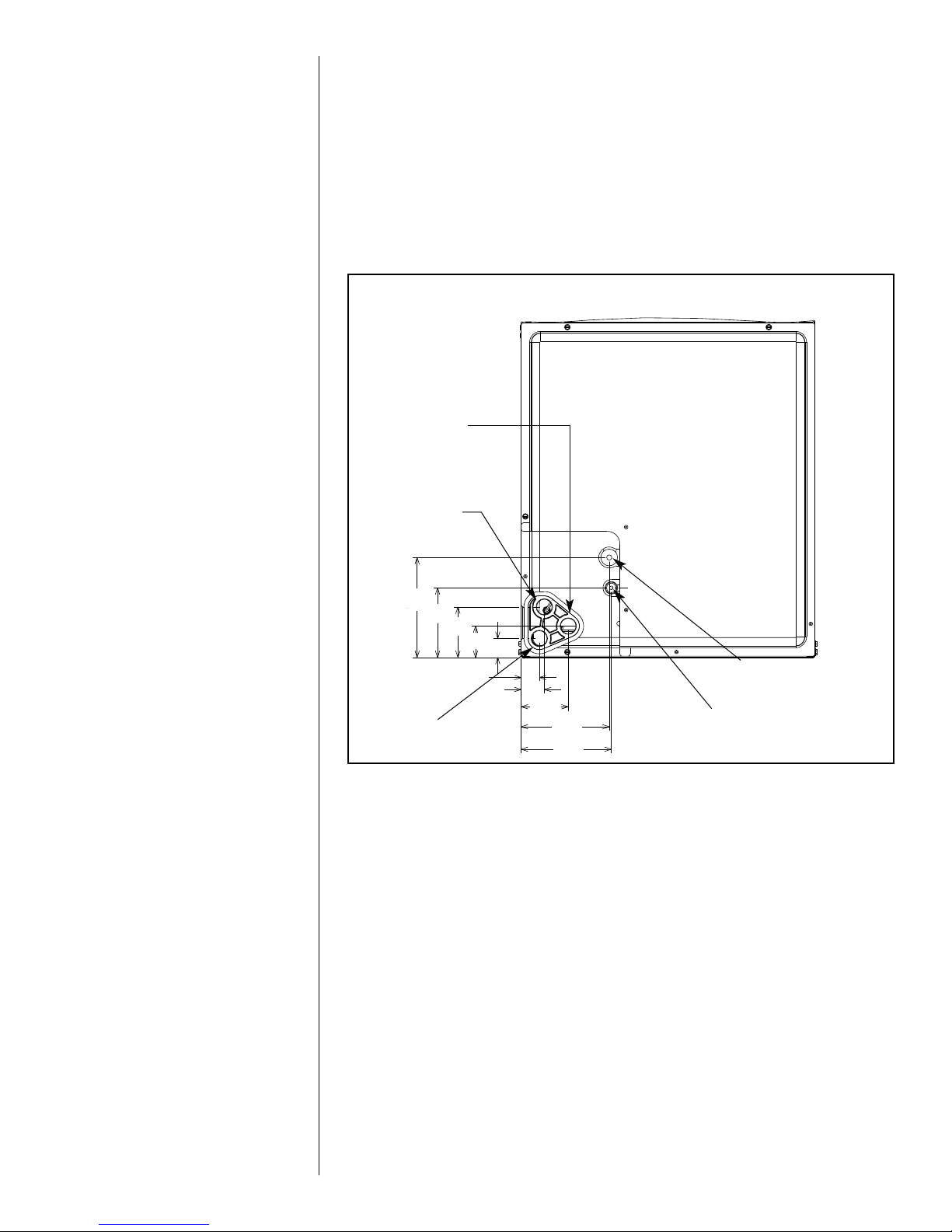
FIGURE 4
IMENSIONS FOR REFRIGERANT-TUBING & DRAIN CONNECTIONS
D
VERTICAL
AUXILIARY DRAIN
CONNECTION
HORIZONTAL
AUXILIARY DRAIN
ONNECTION
C
515/16
41/8
31/16
13/16
11/8
SUCTION LINE
CONNECTION
LIQUID LINE
CONNECTION
MAIN DRAIN
CONNECTION
11/16
13/8
213/16
51/4
53/8
3.2.2 VERTICAL DOWNFLOW & HORIZONTAL RIGHT DISCHARGE
The unit as shipped from the factory is not configured for vertical down or horizontal right
discharge applications and must be converted in the field to work in those applications.
To make this conversion, remove the coil door and slide the indoor coil out of the cabinet.
When converting the air-handler for vertical down and horizontal right discharge applications, an additional set of 2 coil support rails must be installed before the coil can be
reinstalled. These additional rails are supplied with the air-handler and are packaged
with the duct flanges. Six screws are also provided for mounting the rails and can be
found in the installation hardware bag. Clearance holes must be drilled in the sides of
the cabinet for the mounting screws using the provided dimples as guides. Note that the
shorter coil support rail with no notch must be mounted on the left-hand side to provide
clearance for the drainpan condensate connection boss.
The vertical down/horizontal right coil support rails were not installed at the factory so the
insulation under them would not be compressed which could result in exterior cabinet
sweating in humid environments due to that location being in the cold downstream side
of the indoor coil in vertical up and horizontal left discharge applications. The coil support
rails installed at the factory should be left in place to help retain the cabinet insulation.
They will be located on the warmer return side of the air-handler for down and horizontal
right discharge applications and will therefore not pose a risk for cabinet sweating.
Once the additional coils support rails are installed, slide the coil back into the cabinet 180º
from its original position, ensuring the retaining channel is fully engaged with the coil rail.
(See Figure 6, Detail A.) Leave the coil door off until after the refrigerant tubing is brazed to
the refrigerant stubs to allow TXV to be wrapped with a wet rag or heat sink compound
during the brazing process. If the air-handler is not already in position, it can now be positioned so the blower discharge is either down or to the right depending on the application.
13
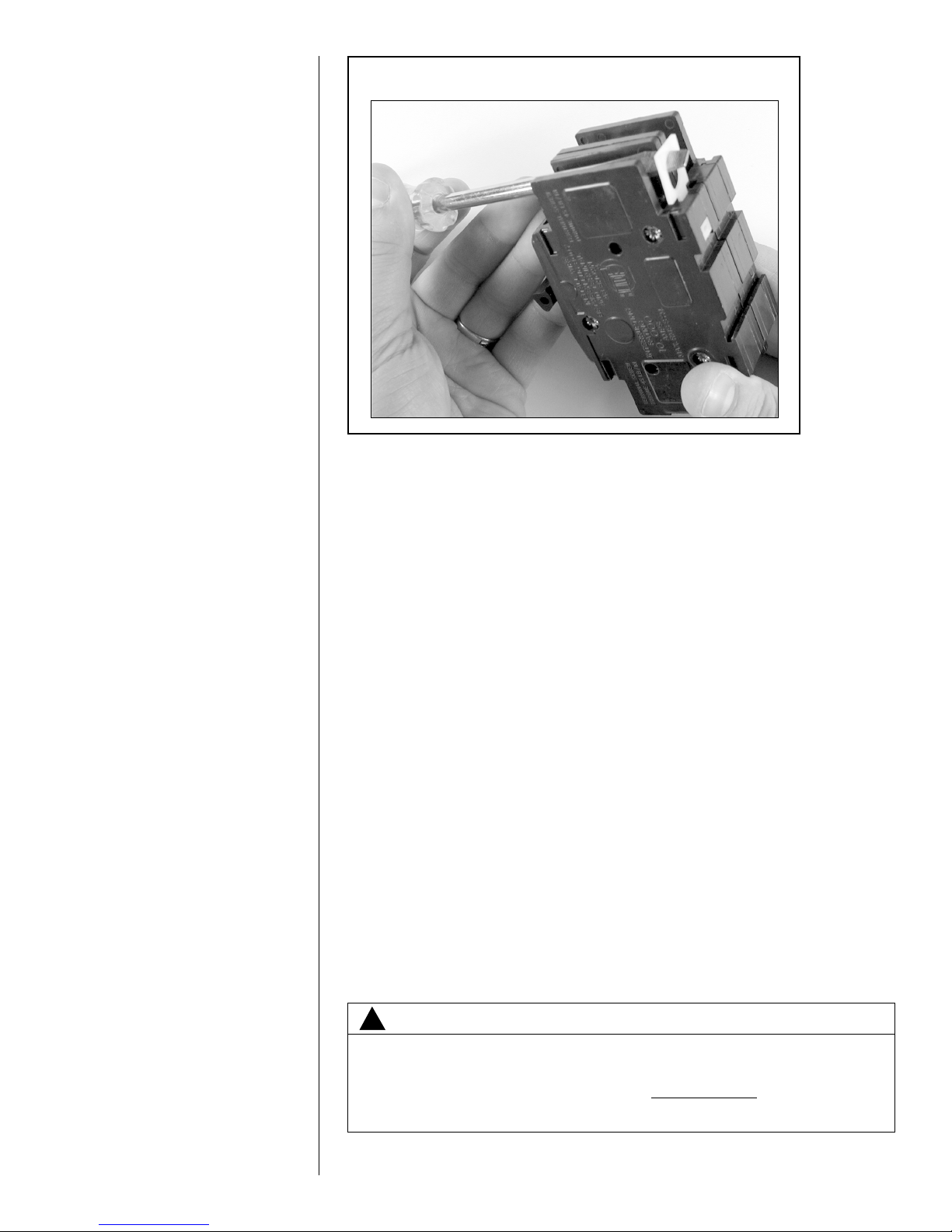
FIGURE 5
OTATING CIRCUIT BREAKER
R
DRIP LOOP NOTE: When installing the unit in down or horizontal right discharge appli-
cations, make sure the wires going to the blower motor form a proper drip loop to force
any condensate that might form on the wires to drip off the lowest point of the wiring
instead of entering the motor or motor control. This may require cutting the wire-tie and
installing a new wire-tie to form a new drip loop.
IMPORTANT: To comply with certification agencies and the National Electric Code for
down discharge applications, the circuit breaker(s) on field-installed electric heater kits
must be re-installed per procedure below so that the breaker switch “on” position and
marking is up and the “off” position and marking is down.
- To turn breaker(s): Rotate one breaker pair (circuit) at a time starting with the one
on the right. Loosen both lugs on the load side of the breaker. Wires are bundles
with wire ties, one bundle going to the right lug and one bundle going to the left lug.
- Using a screwdriver or pencil, lift white plastic tab with hole away from breaker until
breaker releases from mounting opening (see Figure 5).
- With breaker held in hand, rotate breaker so that “on” position is up and the “off”
position is down with unit in the vertical mounting position. Insert right wire bundle
into top right breaker lug, ensuring all strands of all wires are inserted fully into lug,
and no wire insulation is caught in lug.
- Tighten lug as tight as possible while holding circuit breaker. Check wires and
make sure each wire is secure and none are loose. Repeat for left wire bundle in
left top circuit breaker lug.
IMPORTANT: Failure to securely hold the breaker will result in the plastic mounting boss
on the breaker to be broken off when the lug is tightened.
- Replace breaker by inserting breaker mounting tab opposite white pull tab in opening, hook mounting tab over edge in opening.
- With screwdriver or pencil, pull white tab with hole away from breaker while setting
that side of breaker into opening. When breaker is in place, release tab, locking
circuit breaker into location in opening.
- Repeat above operation for remaining breaker(s) (if more than one is provided).
- If one is used, replace the single point wiring jumper bar on line side of breaker
and tighten securely.
- Double check wires and lugs to make sure all are secure and tight. Check to
make sure unit wiring to circuit breaker load lugs match that shown on the unit
wiring diagram.
14
WARNING
!
The RXHB-17, RXHB-21 or RXHB-24 combustible floor base is required
when some units with electric heat are applied downflow on combustible
flooring. Failure to use the base can cause a fire resulting in property
damage, personal injury or death. See CLEARANCES (Section 3.4) for
units requiring a combustible floor base. See the accessory section in this
manual for combustible floor base RXHB.
IMPORTANT: Units cannot be installed horizontally laying on or suspended from the
back of the unit.

IGURE 6
F
ERTICAL DOWNFLOW & HORIZONTAL RIGHT APPLICATIONS
V
FACTORY COIL
RAIL LOCATION
ADDITIONAL
COIL RAILS
DETAIL A
ENSURE THE RETAINING
HANNEL IS FULLY
C
ADDITIONAL
COIL RAILS
ENGAGED WITH THE
COIL RAIL.
FACTORY COIL RAIL LOCATION
FIGURE 7
INDOOR COIL AND DRAIN PAN DETAILS
STRAPS
HORIZONTAL DRIP PAN
VAPOR LINE
CONNECTION
AUXILIARY
HORIZONTAL
DRAIN
CONNECTION
PRIMARY
DRAIN
CONNECTION
UPFLOW/DOWNFLOW
DRAIN CONNECTION
KIT
AUXILIARY
LIQUID LINE
CONNECTION
TOP AIR STOP
VERTICAL
DRAIN PAN
ST-A1213-01
ST-A1213-02
CAUTION
!
Auxiliary horizontal overflow pan kits RXBM- (or equivalent) are required
when the unit is configured for the horizontal position over a finished ceiling and/or living space. (See Sections 3.3 and 6.3.) Failure to install overflow plan can result in property damage.
3.2.3 INSTALLATION IN AN UNCONDITIONED SPACE
The exterior cabinet of an air handler has a greater risk of sweating when installed in an
unconditioned space than when it is installed in the conditioned space. This is primarily
due to the temperature of the conditioned air moving through the air handler and the air
circulating around the unit where it is installed. For this reason, the following is recommended for all air handler applications, but special attention should be paid to those
installed in unconditioned spaces:
• Duct sizing and airflow are critical and must be based on the equipment selected.
• Supply and return duct attachment: If other than the factory flanges are used, the
attachment of ducting must be insulated and tight to prevent sweating.
15
• No perimeter supply flanges are provided. If a full perimeter supply duct is used, it is
the responsibility of the installer to provide duct flanges as needed, to secure and seal
the supply duct to prevent air leakage and the sweating that will result.
• Apply caulking around all cabinet penetrations such as power wires, control wires,
refrigerant tubing and condensate line where they enter the cabinet. Seal the power
wires on the inside where they exit conduit opening. Sealing is required to prevent air
leakage into the unit which can result in condensate forming inside the unit, control
box, and on electrical controls. Take care not to damage, remove or compress insulation when applying the caulk.
• In some cases, the entire air handler can be wrapped with insulation. This can be
done as long as the unit is completely enclosed in insulation, sealed and service
access is provided to prevent accumulation of moisture inside the insulation wrap.
• An auxiliary overflow pan is recommended to protect the structure from excessive
cabinet sweating or a restricted coil drain line. (See Section 3.3)
• If an electric heater kit is installed, be sure the breaker or disconnect cover is sealed
tightly to the door panel.
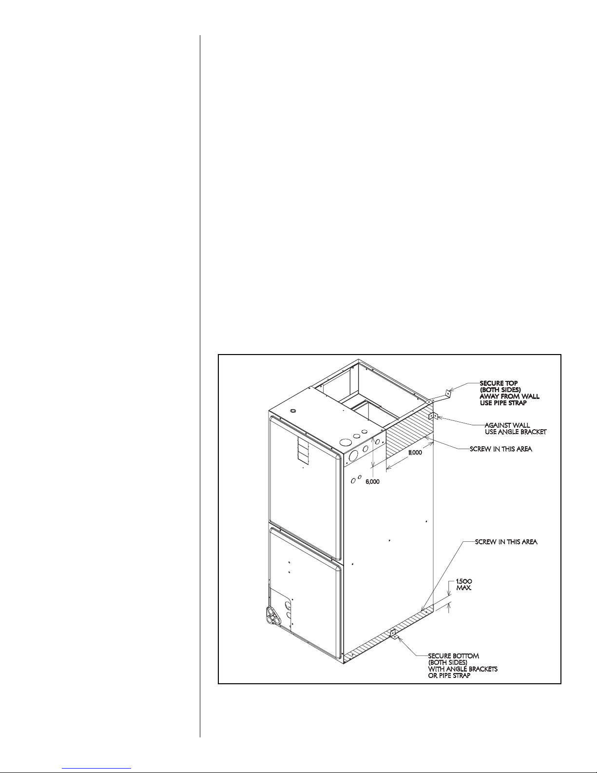
3.2.4 INSTALLATION IN MOBILE/MANUFACTURED HOMES
1. Air handler must be secured to the structure using “L” brackets or pipe strap.
2. Allow a minimum of 24 inches (610 mm) front clearance required to access doors.
3. Recommended method for securing air handler:
A. If air handler is against the wall, secure top of air handler to wall stud using two
16ga thick angle brackets one on each side. Attach brackets with No. 10 self-tap-
1
ping
⁄2 long screws to air handler and use 5⁄16 lag screws 11⁄2 long to wall stud.
Secure bottom of unit with two 16ga “L” brackets with No. 10 self-tapping 1⁄2 long
screws to air handler and use 5⁄16 lag screws 11⁄2 long to floor.
B. If air handler is away from wall attach pipe strap to top of air handler using No. 10
1
⁄2 long self-tapping screws on both sides. Angle strap down and away from back
of air handler, remove all slack, and fasten to wall stud of structure using 5⁄16 lag
screws 11⁄2 long. Secure bottom of unit with two 16ga “L” brackets with No. 10
self-tapping screws to air handler and use 5⁄16 lag screws 11⁄2 long to floor.
FIGURE 8
16
ST-A-1193-01
3.2.5 INSTALLATION IN CORROSIVE ENVIRONMENTS
21” CABINET CUTHERE
HEAT B ARR IE R
17” CABINET CUT HERE
DUCT FLANGE
(2) REQUIRED
BEND
The metal parts of this unit may be subject to rust or deterioration if exposed to a corrosive environment which can shorten its life. In addition to exposure to the exterior of the
cabinet, chemical contaminants inside the building that can be drawn into the unit from
the return air grille and attack structural metal parts, electrical components and the
indoor coil, causing premature failure of the unit. If the unit is to be installed in an area
where contaminants are likely to be a problem, special attention should be given to isolate the unit and return grille from contaminants.
3.3 AUXILIARY OVERFLOW PAN
n compliance with recognized codes, an auxiliary overflow pan must installed under all
I
quipment containing evaporator coils that are located in any area of a structure where
e
amage to the building or building contents may occur as a result of an overflow of the
d
oil drain pan or a stoppage in the primary condensate drain piping. See Section 6.3 of
c
his manual for information regarding the recommended auxiliary horizontal overflow pan
t
model RXBM) for this air-handle.
(
3.4 CLEARANCES
• All units are designed for “0” inches clearance to combustible material on all cabinet
surfaces except for downflow application with higher kW electric heat as noted below.
• Some units require a combustible floor base depending on the heating kW if installed
in the downflow configuration on a combustible surface. The following table should be
used to determine these requirements.
Model Cabinet Size 17 21 24
Maximum Model Designation kW 15 18 20
• Units with electric heating kW equal to or less than the values listed in the table do not
require a combustible floor base. See Section 6.5 for Combustible Floor Base RXHB-XX.
• Units with electric heat require a one inch clearance to combustible material for the
first three feet of supply plenum and ductwork.
• Vertical downflow applications require clearance on at least one side of the unit for
electrical connections. Refrigerant and condensate drain connections are made on
the front of the unit.
• All units require 24 inches minimum access to the front of the unit for service.
• These units may be installed in either ventilated or nonventilated spaces.
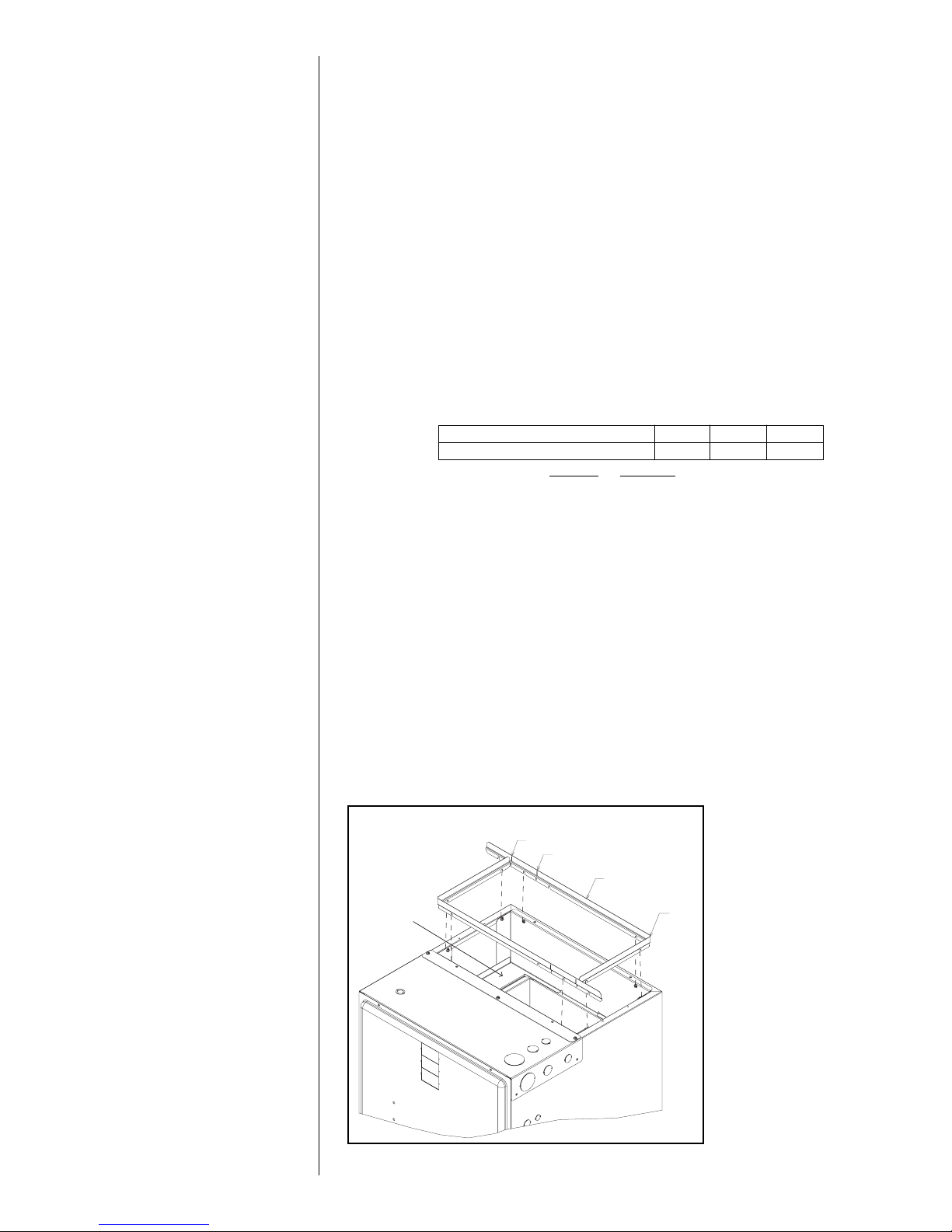
3.5 DUCT FLANGES
Duct flanges (4 pieces) are shipped with the unit and are to be field installed on the top
of the air-handler using the following procedure and referring to Figure 9.
1. Loosen the screws attaching the heat barrier to the cabinet.
2. Form a 90° bend with the short leg length at approximately 9.9” from the end where
the slot is cut in the flange to facilitate bending. The duct flanges are shipped sized for
the 24.5” wide cabinet. For the 17.5” and 21” wide cabinets, cut the long leg as
shown in Figure 9 to match the cabinet width.
3. Side the duct flanges onto the screws loosened in step one above. Tighten the
screws to secure the flanges.
FIGURE 9
DUCT FLANGE INSTALLATION
17
 Loading...