

Rheem RGRK SERIES, RGRL SERIES, RGTK SERIES Installation Instructions Manual
INSTALLATION INSTRUCTIONS
ISO 9001:2008
FOR UPFLOW AND DOWNFLOW/HORIZONTAL
HIGH EFFICIENCY CONDENSING TWO-STAGE
GAS FURNACES
RGRK, RGRL, AND RGTK SERIES
U.L. recognized fuel gas and CO (carbon monoxide) detectors are recommended in all
applications, and their installation should be in accordance with the manufacturer’s
recommendations and/or local laws, rules, regulations, or customs.
92-24161-36-22
SUPERSEDES 92-24161-36-21

INSTALLATION CHECK LIST
REFER TO INSTALLATION INSTRUCTIONS
TERMINATIONS – DIRECT VENT
AS SUPPLY
G
______ Adequate pipe size
_____ Correct supply pressure (during furnace operation)
_
______ Manifold pressure
______ No gas leaks
_____ L.P. Kit Number (if applicable)
_
ELECTRICAL
______ 115 V.A.C. supply (Single Circuit)
______ Polarity observed
______ Furnace properly grounded
______ Adequate wire size
FURNACE INSTALLATION
______ Adequate clearance to combustibles
______ Adequate clearance for service (at front)
VERTICAL
______ Intake – 12" min. above roof/snow level
______ Correct relationship – exhaust to intake
HORIZONTAL/VERTICAL – CONCENTRIC ((-)XGY-E03A)
______ Intake – 12" min. above roof/snow level
______ Intake “Y” rotated above center
______ Exhaust sloped toward furnace
HORIZONTAL – STANDARD ((-)XGY-D02, -D03) – US
((-)XGY-D02A, (-)XGY-D03A) – CANADA
______ Correct relationship – exhaust to intake
______ 12" min. above grade/snow level
HORIZONTAL – ALTERNATE
((-)XGY-D02, -D03 OR -D04) – US
((-)XGY-D02A, -D03A, -D04A) – CANADA
DUCT STATIC PRESSURE
______ in. w.c. on heating speed
______ in. w.c. on cooling speed
______ Air temperature rise
CONDENSATE LINE
______ Trap filled with water
______ Vented
______ Sloped toward drain
______ Condensate drain line hoses connected
and clamped
______ Freeze protection (if necessary)
VENTING – DIRECT VENT
______ in. diameter – intake pipe
______ in. diameter – exhaust pipe
______ ft. of pipe – intake air
______ Correct relationship – exhaust to intake
______ Above anticipated snow level
VENTING – NON-DIRECT VENT
______ in. diameter – exhaust pipe
______ ft. of pipe – exhaust
______ no. of elbows
TERMINATION – NON-DIRECT VENT
VERTICAL
______ 12" min. above roof/snow level
HORIZONTAL – STANDARD
______ 12" min. above grade/snow level
HORIZONTAL – ALTERNATE
______ Above anticipated snow level
______ no. of elbows – intake air
______ ft. of pipe – exhaust pipe
______ no. of elbows – exhaust pipe
______ Exhaust Vent Temperature
2
_____________________________ Model Number
_____________________________ Serial Number
_____________________________ Date of Installation

IMPORTANT: All manufacturer
products meet current Federal OSHA
Guidelines for safety. California
Proposition 65 warnings are required
for certain products, which are not
covered by the OSHA standards.
California's Proposition 65 requires
arnings for products sold in California
w
that contain, or produce, any of over
600 listed chemicals known to the State
f California to cause cancer or birth
o
defects such as fiberglass insulation,
lead in brass, and combustion products
rom natural gas.
f
All “new equipment” shipped for sale in
California will have labels stating that
the product contains and/or produces
Proposition 65 chemicals. Although we
have not changed our processes,
having the same label on all our
products facilitates manufacturing and
shipping. We cannot always know
“when, or if” products will be sold in the
California market.
You may receive inquiries from
customers about chemicals found in, or
produced by, some of our heating and
air-conditioning equipment, or found in
natural gas used with some of our
products. Listed below are those
chemicals and substances commonly
associated with similar equipment in
our industry and other manufacturers.
• Glass Wool (Fiberglass) Insulation
• Carbon Monoxide (CO)
• Formaldehyde
• Benzene
More details are available at the
Websites for OSHA (Occupational
Safety and Health Administration), at
www.osha.gov
California's OEHHA (Office of
Environmental Health Hazard
Assessment), at www.oehha.org.
Consumer education is important since
the chemicals and substances on the
list are found in our daily lives. Most
consumers are aware that products
present safety and health risks, when
improperly used, handled and
maintained.
and the State of
CONTENTS
afety Precautions ...................................................................................................1
S
nstallation Check List ..............................................................................................2
I
eneral Information..................................................................................................4
G
afety Information ....................................................................................................6
S
ocation Requirements and Considerations ............................................................8
L
ucting ...................................................................................................................13
D
enting and Combustion Air Piping .......................................................................15
V
ombustion and Ventilation Air ..............................................................................17
C
ent Pipe Installation..............................................................................................20
V
Condensate Drain/Neutralizer................................................................................33
Gas Supply and Piping...........................................................................................37
Electrical Wiring......................................................................................................42
Accessories............................................................................................................43
Furnace Twinning...................................................................................................44
High Altitude Installations.......................................................................................48
Start-Up Procedures...............................................................................................51
Air Flow...................................................................................................................54
Maintenance...........................................................................................................57
Troubleshooting......................................................................................................59
Wiring Diagram.......................................................................................................62
3
GENERAL INFORMATION
NOTE: A load calculation must be
performed to properly determine the
required furnace BTU size for the
structure. Also, the duct must be properly
designed and installed for proper airflow.
Existing ductwork must be inspected for
proper size and sealed system. Proper
airflow is necessary for both user comfort
and equipment performance.
Before opening the furnace carton and
installation of the furnace, verify the data
tags on the carton and inside the
furnace, match and is what was ordered
from the local distributor. Also, check for
any damage to the furnace before
installation.
IMPORTANT: Proper application,
installation and maintenance of this
furnace and system is a must if
consumers are to receive the full benefits
for which they have paid.
The (-)GRK-, (-)GRL-, (-)GTK- series
furnaces are design-certified by CSA for
use with natural and propane gases as
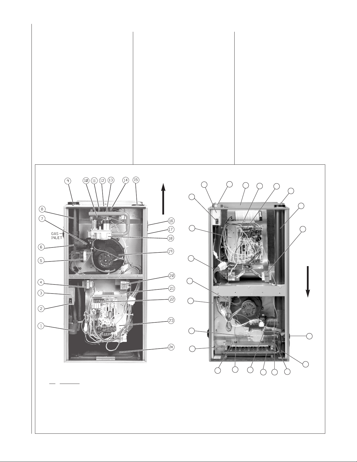
FIGURE 1
UPFLOW FURNACE COMPONENTS
follows:
1. As non-direct vent central forced air
furnaces taking combustion air from
the installation area or using air
ducted from the outside.
2. As direct vent central forced air
furnaces with all combustion air
supplied directly to the furnace
burners through a special air intake
system outlined in these
instructions.Install this furnace in
accordance with the American
National Standard Z223.1 – latest
edition entitled “National Fuel Gas
Code” (NFPA54) and requirements
or codes of the local utilities or
other authorities having jurisdiction.
This is available from the following:
National Fire Protection
Association, Inc.
Batterymarch Park
Quincy, MA 02269
OWNFLOW/HORIZONTAL FURNACE COMPONENTS
D
AIRFLOW
3
2
CSA-INTERNATIONAL
8501 East Pleasant Valley Road
Cleveland, Ohio 44131-5575
Install units in Canada in accordance
with CSA-B149, local installation
codes and authorities having
jurisdiction. CSA-B149 is available
from:
CSA-INTERNATIONAL
178 Rexdale Blvd.
Toronto, Ontario
Canada M9W, 1R3
NOTE: It is our recommendation that
any HVAC equipment which were
subject to flooding be replaced to
avoid any risk of property damage,
personal injury or death. Also, our
position that the immersion by flood
waters compromises any HVAC
products thus voiding this warranty.
15
12
23
22
9
8
ITEM
NO. PART NAME
1 CONDENSATE TRAP
2 DOOR SWITCH
3 JUNCTION BOX
4 TRANSFORMER
5 PRESSURE SWITCHES
6 EXHAUST TRANSITION
7 CONNECTOR
8 OUTLET AIR PIPE
NOTE: A PARTS BAG IS INCLUDED WITH THE FURNACE. IF A NEW
PARTS BAG NEEDS TO BE ORDERED, USE THE FOLLOWING PART
NUMBERS: AS-100717-01 FOR (-)GRL-45, (-)GRL-60, (-)GRK-75, (-)GRL90 AND (-)GRK-105 AS-100717-02 FOR (-)GRK-120
9 SHIPPING PLUG (TO BE REMOVED)
10 FLAME SENSOR
11 OVERTEMPERATURE SWITCH
12 TOP PLATE
13 BURNER
14 IGNITER
15 COMBUSTION AIR INLET
16 OPTIONAL AIR INLET (UPFLOW UNITS ONLY)
17 OPTIONAL GAS INLET
18 GAS VALVE
21
20
19
5
18
10
11
25
19 INDUCED DRAFT BLOWER
20 CAPACITORS
21 BLOWER
22 LOW VOLTAGE TERMINAL
23 CONTROL MOUNTING PLATE
24 FILTER / SOLID METAL BASEPLATE (UPFLOW
UNITS ONLY)
25 BURNER COVER PLATE
NOTE: A PARTS BAG IS INCLUDED WITH THE FURNACE. IF A NEW
PARTS BAG NEEDS TO BE ORDERED, USE THE FOLLOWING PART
NUMBERS: AS-100717-03 FOR (-)GTK-60, (-)GTK-75, (-)GTK-90, (-)GTK105 AND (-)GTK-120
7
(DOWNFLOW/HORIZONTAL UNITS ONLY)
6
13
4
AIRFLOW
17
1
14
4

IMPORTANT INFORMATION
ABOUT EFFICIENCY AND
INDOOR AIR QUALITY
Central cooling and heating equipment
is only as efficient as the duct system
that carries the cooled or heated air. To
maintain efficiency, comfort and good
indoor air quality, it is important to have
he proper balance between the air
t
being supplied to each room and the air
returning to the cooling and heating
equipment.
Proper balance and sealing of the duct
system improves the efficiency of the
heating and air conditioning system
and improves the indoor air quality of
the home by reducing the amount of
airborne pollutants that enter homes
from spaces where the ductwork and /
or equipment is located. The
manufacturer and the U.S.
Environmental Protection Agency’s
Energy Star Program recommend that
central duct systems be checked by a
qualified contractor for proper balance
and sealing.
WARNING
!
DUCT LEAKS CAN CREATE AN
UNBALANCED SYSTEM AND DRAW
POLLUTANTS SUCH AS DIRT, DUST,
FUMES AND ODORS INTO THE
HOME CAUSING PROPERTY
DAMAGE. FUMES AND ODORS
FROM TOXIC, VOLATILE OR
FLAMMABLE CHEMICALS, AS WELL
AS AUTOMOBILE EXHAUST AND
CARBON MONOXIDE (CO), CAN BE
DRAWN INTO THE LIVING SPACE
THROUGH LEAKING DUCTS AND
UNBALANCED DUCT SYSTEMS
CAUSING PERSONAL INJURY OR
DEATH (SEE FIGURE 2).
• IF AIR-MOVING EQUIPMENT OR
DUCTWORK IS LOCATED IN
GARAGES OR OFF-GARAGE
STORAGE AREAS - ALL JOINTS,
SEAMS, AND OPENINGS IN THE
EQUIPMENT AND DUCT MUST BE
SEALED TO LIMIT THE MIGRATION
OF TOXIC FUMES AND ODORS
INCLUDING CARBON MONOXIDE
FROM MIGRATING INTO THE
LIVING SPACE.
• IF AIR-MOVING EQUIPMENT OR
DUCTWORK IS LOCATED IN
SPACES CONTAINING FUEL
BURNING APPLIANCES SUCH AS
WATER HEATERS OR BOILERS ALL JOINTS, SEAMS, AND
OPENINGS IN THE EQUIPMENT
AND DUCT MUST ALSO BE
SEALED TO PREVENT
DEPRESSURIZATION OF THE
SPACE AND POSSIBLE
MIGRATION OF COMBUSTION
BYPRODUCTS INCLUDING
CARBON MONOXIDE INTO THE
LIVING SPACE.
FIGURE 2
MIGRATION OF DANGEROUS SUBSTANCES, FUMES, AND ODORS INTO LIVING SPACES
NOTICE
IMPROPER INSTALLATION, OR
INSTALLATION NOT MADE IN
ACCORDANCE WITH THE CSA
INTERNATIONAL (CSA)
CERTIFICATION OR THESE
INSTRUCTIONS, CAN RESULT IN
UNSATISFACTORY OPERATION
AND/OR DANGEROUS CONDI-TIONS
AND ARE NOT COVERED BY THE
UNIT WARRANTY.
NOTICE
IN COMPLIANCE WITH
RECOGNIZED CODES, IT IS
RECOMMENDED THAT AN
AUXILIARY DRAIN PAN BE
INSTALLED UNDER ALL
EVAPORATOR COILS OR UNITS
CONTAINING EVAPORATOR COILS
THAT ARE LOCATED IN ANY AREA
OF A STRUCTURE WHERE DAMAGE
TO THE BUILDING OR BUILDING
CONTENTS MAY OCCUR AS A
RESULT OF AN OVERFLOW OF THE
COIL DRAIN PAN OR A STOPPAGE
IN THE PRIMARY CONDENSATE
DRAIN PIPING. SEE ACCESSORIES
SECTION OF THESE INSTRUCTIONS
FOR AUXILIARY HORIZONTAL
OVERFLOW PAN INFORMATION
(MODEL (-)XBM).
RECEIVING
Immediately upon receipt, all cartons
and contents should be inspected for
transit damage. Units with damaged
cartons should be opened immediately.
If damage is found, it should be noted
on the delivery papers, and a damage
claim filed with the last carrier.
• After unit has been delivered to job
site, remove carton taking care not to
damage unit.
• Check the unit rating plate for unit
size, electric heat, coil, voltage,
phase, etc. to be sure equipment
matches what is required for the
job specification.
• Read the entire instructions before
starting the installation.
• Some building codes require extra
cabinet insulation and gasketing
when unit is installed in attic
applications.
• If installed in an unconditioned
space, apply caulking around the
power wires, control wires,
refrigerant tubing and condensate
line where they enter the cabinet.
Seal the power wires on the inside
where they exit conduit opening.
Caulking is required to prevent air
leakage into and condensate from
forming inside the unit, control box,
and on electrical controls.
• Install the unit in such a way as to
allow necessary access to the
coil/filter rack and blower/control
compartment.
• Install the unit in a level position to
ensure proper condensate
drainage. Make sure unit is level in
both directions within 1/8”.
• Install the unit in accordance with
any local code which may apply
and the national codes. Latest
editions are available from:
“National Fire Protection
Association, Inc., Batterymarch
Park, Quincy, MA 02269.” These
publications are:
• ANSI/NFPA No. 70-(Latest Edition)
National Electrical Code.
• NFPA90A Installation of Air
Conditioning and Ventilating
Systems.
• NFPA90B Installation of warm air
heating and air conditioning
systems.
• The equipment has been
evaluated in accordance with the
Code of Federal Regulations,
Chapter XX, Part 3280.
5

SAFETY INFORMATION
WARNING
!
USE ONLY WITH TYPE OF GAS
APPROVED FOR THIS FURNACE.
REFER TO THE FURNACE RATING
PLATE.
WARNING
!
INSTALL THIS FURNACE ONLY IN
A LOCATION AND POSITION AS
SPECIFIED IN THE LOCATION
REQUIREMENTS AND
CONSIDERATIONS SECTION OF
THESE INSTRUCTIONS. PROVIDE
ADEQUATE COMBUSTION AND
VENTILATION AIR TO THE
FURNACE SPACE AS SPECIFIED
IN THE VENTING SECTION OF
THESE INSTRUCTIONS.
WARNING
!
PROVIDE ADEQUATE
COMBUSTION AND VENTILATION
AIR TO THE FURNACE SPACE AS
SPECIFIED IN THE COMBUSTION
AND VENTILATION AIR SECTION
OF THESE INSTRUCTIONS.
WARNING
!
COMBUSTION PRODUCTS MUST
BE DISCHARGED OUTDOORS.
CONNECT THIS FURNACE TO AN
APPROVED VENT SYSTEM ONLY,
AS SPECIFIED IN VENT PIPE
INSTALLATION SECTION OF
THESE INSTRUCTIONS.
WARNING
!
DO NOT OPERATE THE SYSTEM
WITHOUT FILTERS. A PORTION
OF THE DUST ENTRAINED IN THE
AIR MAY TEMPORARILY LODGE IN
THE AIR DUCT RUNS AND AT THE
SUPPLY REGISTERS. ANY
CIRCULATED DUST PARTICLES
WILL BE HEATED AND CHARRED
BY CONTACT WITH THE FURNACE
HEAT EXCHANGER. THIS SOOTY
RESIDUE WILL SOIL CEILINGS,
WALLS, DRAPES, CARPETS AND
OTHER HOUSEHOLD ARTICLES.
SOOT DAMAGE MAY ALSO
RESULT WITH, OR WITHOUT,
FILTERS IN PLACE, WHEN
CERTAIN TYPES OF CANDLES
ARE BURNED, OR CANDLEWICKS
ARE LEFT UNTRIMMED.
WARNING
!
NEVER TEST FOR GAS LEAKS
WITH AN OPEN FLAME. USE A
COMMERCIALLY AVAILABLE
OAP SOLUTION MADE
S
SPECIFICALLY FOR THE
DETECTION OF LEAKS TO CHECK
ALL CONNECTIONS, AS
SPECIFIED IN GAS SUPPLY AND
PIPING SECTION OF THESE
INSTRUCTIONS.
WARNING
!
ALWAYS INSTALL FURNACE TO
OPERATE WITHIN THE
FURNACE'S INTENDED
TEMPERATURE-RISE RANGE
WITH A DUCT SYSTEM WHICH
HAS AN EXTERNAL STATIC
PRESSURE WITHIN THE
ALLOWABLE RANGE, AS
SPECIFIED IN DUCTING SECTION
OF THESE INSTRUCTIONS. SEE
ALSO FURNACE RATING PLATE.
WARNING
!
WHEN A FURNACE IS INSTALLED
SO THAT SUPPLY DUCTS CARRY
AIR CIRCULATED BY THE
FURNACE TO AREAS OUTSIDE
THE SPACE CONTAINING THE
FURNACE, THE RETURN AIR
SHALL ALSO BE HANDLED BY
DUCT(S) SEALED TO THE
FURNACE CASING AND
TERMINATING OUTSIDE THE
SPACE CONTAINING THE
FURNACE.
WARNING
!
DO NOT INSTALL THIS FURNACE
IN A MOBILE HOME!! THIS
FURNACE IS NOT APPROVED FOR
INSTALLATION IN A MOBILE
HOME. DOING SO COULD CAUSE
FIRE, PROPERTY DAMAGE,
PERSONAL INJURY OR DEATH.
WARNING
!
HEN THIS FURNACE IS
W
INSTALLED IN A RESIDENTIAL
GARAGE, IT MUST BE INSTALLED
SO THE BURNERS AND IGNITION
SOURCE ARE LOCATED NO LESS
THAN 18 INCHES ABOVE THE
FLOOR. THIS IS TO REDUCE THE
RISK OF IGNITING FLAMMABLE
VAPORS WHICH MAY
E PRESENT IN A GARAGE.
B
ALSO, THE FURNACE MUST BE
LOCATED OR PROTECTED TO
AVOID PHYSICAL DAMAGE BY
VEHICLES. FAILURE TO FOLLOW
THESE WARNINGS CAN CAUSE A
FIRE OR EXPLOSION, RESULTING
IN PROPERTY DAMAGE,
PERSONAL INJURY OR DEATH.
WARNING
!
THE FURNACE MAY BE USED FOR
HEATING OF BUILDINGS OR
STRUCTURES UNDER
CONSTRUCTION.
INSTALLATION MUST COMPLY
WITH ALL INSTALLATION
INSTRUCTIONS INCLUDING:
• PROPER VENT INSTALLATION;
• FURNACE OPERATING UNDER
THERMOSTATIC CONTROL;
• RETURN AIR DUCT SEALED TO
THE FURNACE;
• AIR FILTERS IN PLACE;
• SET FURNACE INPUT RATE
AND TEMPERATURE RISE PER
RATING PLATE MARKING;
• MEANS FOR PROVIDING
OUTDOOR AIR REQUIRED FOR
COMBUSTION;
• RETURN AIR TEMPERATURE
MAINTAINED BETWEEN 55°F
(13°C) AND 80°F (27°C); AND
• CLEAN FURNACE, DUCT WORK
AND COMPONENTS UPON
SUBSTANTIAL COMPLETION OF
THE CONSTRUCTION
PROCESS, AND VERIFY
FURNACE OPERATING
CONDITIONS INCLUDING
IGNITION, INPUT RATE,
TEMPERATURE RISE AND
VENTING, ACCORDING TO THE
INSTRUCTIONS AND CODES.
6
WARNING
!
DUCT LEAKS CAN CREATE AN
UNBALANCED SYSTEM AND DRAW
POLLUTANTS SUCH AS DIRT, DUST,
FUMES AND ODORS INTO THE
HOME CAUSING PROPERTY
DAMAGE. FUMES AND ODORS
FROM TOXIC, VOLATILE OR
FLAMMABLE CHEMICALS, AS WELL
AS AUTOMOBILE EXHAUST AND
CARBON MONOXIDE (CO), CAN BE
DRAWN INTO THE LIVING SPACE
THROUGH LEAKING DUCTS AND
UNBALANCED DUCT SYSTEMS
CAUSING PERSONAL INJURY OR
DEATH (SEE FIGURE 2).
• IF AIR-MOVING EQUIPMENT OR
DUCTWORK IS LOCATED IN
GARAGES OR OFF-GARAGE
STORAGE AREAS - ALL JOINTS,
SEAMS, AND OPENINGS IN THE
EQUIPMENT AND DUCT MUST BE
SEALED TO LIMIT THE MIGRATION
OF TOXIC FUMES AND ODORS
INCLUDING CARBON MONOXIDE
FROM MIGRATING INTO THE
LIVING SPACE.
• IF AIR-MOVING EQUIPMENT OR
DUCTWORK IS LOCATED IN
SPACES CONTAINING FUEL
BURNING APPLIANCES SUCH AS
WATER HEATERS OR BOILERS ALL JOINTS, SEAMS, AND
OPENINGS IN THE EQUIPMENT
AND DUCT MUST ALSO BE
SEALED TO PREVENT
DEPRESSURIZATION OF THE
SPACE AND POSSIBLE
MIGRATION OF COMBUSTION
BYPRODUCTS INCLUDING
CARBON MONOXIDE INTO THE
LIVING SPACE.
NOTICE
IMPROPER INSTALLATION, OR
INSTALLATION NOT MADE IN
ACCORDANCE WITH THE CSA
INTERNATIONAL (CSA)
CERTIFICATION OR THESE
INSTRUCTIONS, CAN RESULT IN
UNSATISFACTORY OPERATION
AND/OR DANGEROUS CONDI-TIONS
AND ARE NOT COVERED BY THE
UNIT WARRANTY.
NOTICE
IN COMPLIANCE WITH RECOGNIZED
CODES, IT IS RECOMMENDED THAT
AN AUXILIARY DRAIN PAN BE
INSTALLED UNDER ALL
EVAPORATOR COILS OR UNITS
CONTAINING EVAPORATOR COILS
THAT ARE LOCATED IN ANY AREA
OF A STRUCTURE WHERE DAMAGE
TO THE BUILDING OR BUILDING
CONTENTS MAY OCCUR AS A
RESULT OF AN OVERFLOW OF THE
COIL DRAIN PAN OR A STOPPAGE IN
THE PRIMARY CONDENSATE DRAIN
PIPING. SEE ACCESSORIES
SECTION OF THESE INSTRUCTIONS
FOR AUXILIARY HORIZONTAL
OVERFLOW PAN INFORMATION
(MODEL (-)XBM).
IMPORTANT!
THE COMMONWEALTH OF
MASSACHUSETTS REQUIRES
COMPLIANCE WITH REGULATION
248 CMR 4.00 AND 5.00 FOR
INSTALLATION OF THROUGH-THEWALL VENTED GAS APPLIANCES AS
FOLLOWS:
(a) For all side wall horizontally vented
gas fueled equipment installed in every
dwelling, building or structure used in
whole or in part for residential purposes,
including those owned or operated by
the Commonwealth and where the side
wall exhaust vent termination is less than
seven (7) feet above finished grade in
the area of the venting, including but not
limited to decks and porches, the
following requirements shall be satisfied:
1. INSTALLATION OF CARBON
MONOXIDE DETECTORS. At the time
of installation of the side wall horizontal
vented gas fueled equipment, the
installing plumber or gasfitter shall
observe that a hard wired carbon
monoxide detector with an alarm and
battery back-up is installed on the floor
level where the gas equipment is to be
installed. In addition, the installing
plumber or gasfitter shall observe that a
battery operated or hard wired carbon
monoxide detector with an alarm is
installed on each additional level of the
dwelling, building or structure served by
the side wall horizontal vented gas
fueled equipment. It shall be the
responsibility of the property owner to
secure the services of qualified licensed
professionals for the installation of hard
wired carbon monoxide detectors.
a. In the event that the side wall
horizontally vented gas fueled equipment
is installed in a crawl space or an attic,
the hard wired carbon monoxide detector
with alarm and battery back-up may be
installed on the next adjacent floor level.
b. In the event that the requirements of
this subdivision can not be met at the
time of completion of installation, the
owner shall have a period of thirty (30)
days to comply with the above
requirements; provided, however, that
during said thirty (30) day period, a
battery operated carbon monoxide
detector with an alarm shall be installed.
2. APPROVED CARBON MONOXIDE
DETECTORS. Each carbon monoxide
detector as required in accordance with
the above provisions shall comply with
NFPA 720 and be ANSI/UL 2034 listed
and IAS certified.
3. SIGNAGE. A metal or plastic
identification plate shall be permanently
mounted to the exterior of the building at
a minimum height of eight (8) feet above
grade directly in line with the exhaust
vent terminal for the horizontally vented
gas fueled heating appliance or
equipment. The sign shall read, in print
size no less than one-half (1/2) inch in
size, “GAS VENT DIRECTLY BELOW.
KEEP CLEAR OF ALL
OBSTRUCTIONS”.
4. INSPECTION. The state or local
gas inspector of the side wall
horizontally vented gas fueled
equipment shall not approve the
installation unless, upon inspection,
the inspector observes carbon
monoxide detectors and signage
installed in accordance with the
provisions of 248 CMR 5.08(2)(a) 1
through 4.
(b) EXEMPTIONS: The following
equipment is exempt from 248 CMR
5.08(2)(a)1 through 4:
1. The equipment listed in Chapter 10
entitled “Equipment Not Required To
Be Vented” in the most current edition
of NFPA 54 as adopted by the Board;
and
2. Product Approved side wall
horizontally vented gas fueled
equipment installed in a room or
structure separate from the dwelling,
building or structure used in whole or
in part for residential purposes.
(c) MANUFACTURER
REQUIREMENTS – GAS
EQUIPMENT VENTING SYSTEM
PROVIDED. When the manufacturer
of Product Approved side wall
horizontally vented gas equipment
provides a venting system design or
venting system components with the
equipment, the instructions provided
by the manufacturer for installation of
the equipment and the venting
system shall include:
1. Detailed instructions for the
installation of the venting system
design or the venting system
components; and
2. A complete parts list for the venting
system design or venting system.
(d) MANUFACTURER
REQUIREMENTS – GAS
EQUIPMENT VENTING SYSTEM
NOT PROVIDED. When the
manufacturer of a Product Approved
side wall horizontally vented gas
fueled equipment does not provide
the parts for venting the flue gases,
but identifies “special venting
systems”, the following requirements
shall be satisfied by the manufacturer:
1. The referenced “special venting
system” instructions shall be included
with the appliance or equipment
installation instructions; and
2. The “special venting systems” shall
be Product Approved by the Board,
and the instructions for that system
shall include a parts list and detailed
installation instructions.
(e) A copy of all installation
instructions for all Product Approved
side wall horizontally vented gas
fueled equipment, all venting
instructions, all parts lists for venting
instructions, and/or all venting design
instructions shall remain with the
appliance or equipment at the
completion of the installation.
7
LOCATION REQUIREMENTS AND CONSIDERATIONS
GENERAL INFORMATION
. install a parallel duct system
WARNING
!
DO NOT INSTALL THIS FURNACE
IN A MOBILE HOME!! This furnace is
not approved for installation in a
mobile home. Doing so could cause
IRE, PROPERTY DAMAGE,
F
PERSONAL INJURY OR DEATH.
WARNING
!
WHEN THIS FURNACE IS
INSTALLED IN A RESIDENTIAL
GARAGE, IT MUST BE INSTALLED
SO THE BURNERS AND IGNITION
SOURCE ARE LOCATED NO LESS
THAN 18 INCHES ABOVE THE
FLOOR. THIS IS TO PREVENT
THE RISK OF IGNITING
FLAMMABLE VAPORS WHICH MAY
BE PRESENT IN A GARAGE.
ALSO, THE FURNACE MUST BE
LOCATED OR PROTECTED TO
AVOID PHYSICAL DAMAGE BY
VEHICLES. FAILURE TO FOLLOW
THESE WARNINGS CAN CAUSE A
FIRE OR EXPLOSION, RESULTING
IN PROPERTY DAMAGE,
PERSONAL INJURY OR DEATH.
1. IMPORTANT: If installing the unit
over a finished ceiling or living
area, be certain to install an
auxiliary condensate drain pan
under the entire unit. This
auxiliary drain pan should extend
under any evaporator coil
installed with the furnace and the
open portion of the condensate
drain assembly. See
“Condensate Drain/Neutralizer”
section for more details.
2. IMPORTANT: If using a cooling
evaporator coil with this furnace:
a. be sure the air passes over
the heat exchanger before
passing over the cooling
coil. The cooled air passing
over the warm ambient air
inside the heat exchanger
tubes can cause
condensation inside the tubes
resulting in corrosion and
eventual failure.
b
to divert all the air from the
furnace allowing it to pass
over the cooling coil only. Use
dampers or other means to
prevent chilled air from
passing over the heat
exchanger.
If these are manual dampers, they
must be equipped to prevent heating
or cooling operation unless the
damper is in the full heat or cool
position.
3. IMPORTANT: Install the furnace
level. If it is not level, condensate
cannot drain properly, possibly
causing furnace shut down.
NOTE: These furnaces are approved
for installation in attics, as well as
alcoves, utility rooms, closets and
crawlspaces. Provisions must be
made to prevent freezing of
condensate.
4. IMPORTANT: If this furnace is
installed in a garage, attic and/or
any unconditioned space, install a
self-regulating heat tape around
the condensate trap and along the
entire length of the condensate
drain in the unconditioned space.
When the condensing horizontal
gas furnace is installed in an
unconditioned space where the
temperature would be capable of
reaching close to or below 32°F
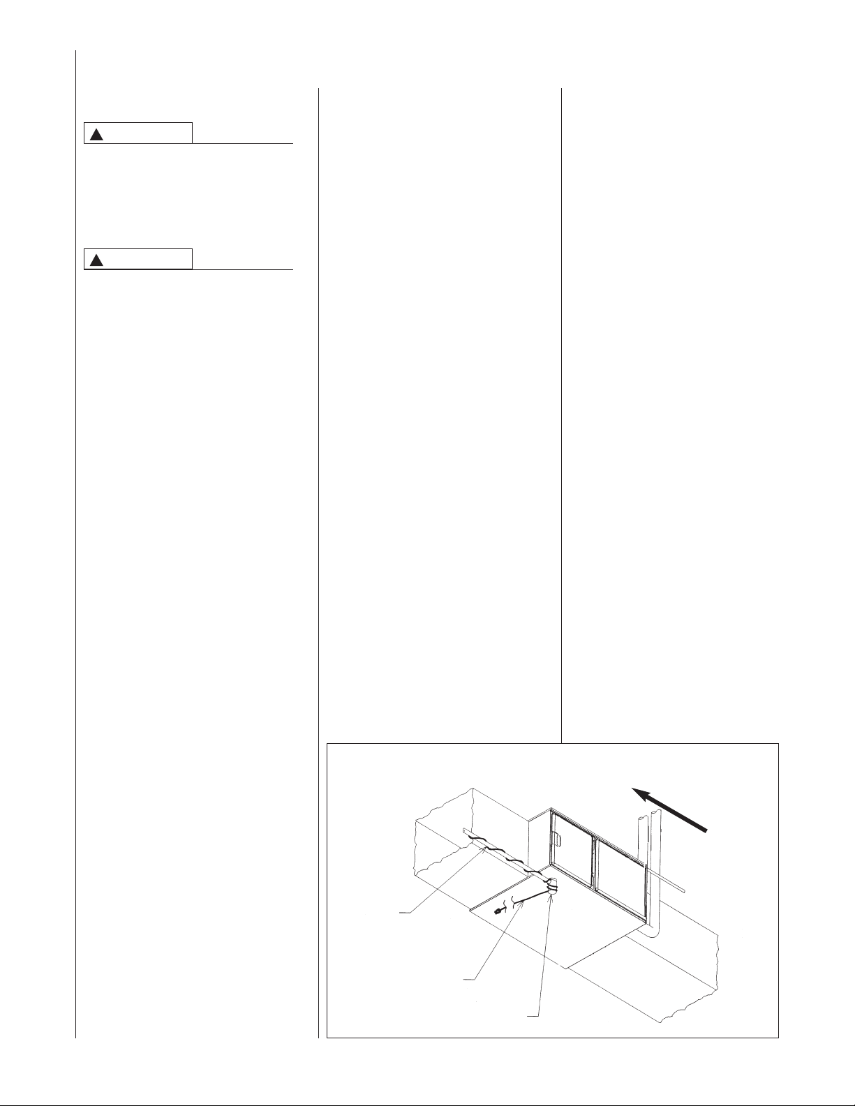
FIGURE 3
HORIZONTAL FURNACE W/HEAT TAPE ON CONDENSATE TRAP
DRAIN
PIPE
5. IMPORTANT: If installing in a
0°C), a self-regulating heat tape
(
is required on the condensate
drain, along with an insulation
wrap. The heat tape should meet
the following requirements:
a. The heat tape must be UL
listed.
b. The heat tape must be
installed per the
manufacturer’s instructions for
the entire length of drain pipe
in the unconditioned space.
c. The heat tape should be rated
at 5 or 6 watts per foot at
120V
IMPORTANT: Support this unit
when installed. Since this furnace
is suitable for attic or crawl space
installation, it may be installed on
combustible wood flooring or by
using support brackets.
utility room, be sure the door is
wide enough to:
a. allow the largest part of the
furnace to pass; or
b. allow any other appliance
(such as a water heater)
to pass.
c. allow service clearance
AIRF
LOW
HEAT
TAPE
TRAP
8
I526
CAUTION
!
THIS FURNACE IS NOT
APPROVED OR RECOMMENDED
FOR INSTALLATION ON ITS BACK,
WITH ACCESS DOORS FACING
UPWARDS OR IN ANY
ORIZONTAL CONFIGURATION.
H
SITE SELECTION
1. Select a site in the building near
he center of the proposed, or
t
existing, duct system.
2. Give consideration to the vent
system piping when selecting the
furnace location. Be sure the
venting system can get from the
furnace to the termination with
minimal length and elbows.
3. Locate the furnace near the
existing gas piping. Or, if running
a new gas line, locate the
furnace to minimize the length
and elbows in the gas piping.
4. Locate the furnace to maintain
proper clearance to combustibles
as shown in the following tables.
WARNING
!
DO NOT LIFT THE UNIT BY THE
HEAT EXCHANGER TUBES. DOING
SO CAN DAMAGE THE HEAT
EXCHANGER ASSEMBLY.
CLEARANCE ACCESSIBILITY
The design of forced air furnaces with
input ratings as listed in the table
under Figure 5 are certified by CSAInternational for the clearances to
combustible materials shown in
inches.
See name/rating plate and clearance
label for specific model number and
learance information.
c
Service clearance of at least 24
inches is recommended in front of
all furnaces.
NOTE: Use recommended 24”
clearance if accessibility clearances
are greater than fire protection
clearances.
WARNING
!
UPFLOW FURNACES ARE DESIGNCERTIFIED FOR INSTALLATION
ON COMBUSTIBLE FLOORS.
NOTE, HOWEVER, THAT
FURNACES MUST NOT BE
INSTALLED DIRECTLY ON
CARPETING, TILE OR OTHER
COMBUSTIBLE MATERIAL OTHER
THAN WOOD FLOORING.
INSTALLATION ON A
COMBUSTIBLE MATERIAL CAN
RESULT IN FIRE, CAUSING
PROPERTY DAMAGE, PERSONAL
INJURY OR DEATH.
Upflow furnaces are shipped with a
bottom closure panel installed. When
bottom return air is used, remove the
panel by removing the two screws
attaching the panel to the front base
angle. See filter section for details.
WARNING
!
COMBUSTIBLE MATERIAL MUST
NOT BE PLACED ON OR AGAINST
THE FURNACE JACKET. THE AREA
AROUND THE FURNACE MUST BE
KEPT CLEAR AND FREE OF ALL
COMBUSTIBLE MATERIALS
INCLUDING GASOLINE AND
OTHER FLAMMABLE VAPORS AND
LIQUIDS. PLACEMENT OF
COMBUSTIBLE MATERIALS ON,
AGAINST OR AROUND THE
FURNACE JACKET CAN CAUSE AN
EXPLOSION OR FIRE RESULTING
IN PROPERTY DAMAGE,
PERSONAL INJURY OR DEATH.
THE HOMEOWNER SHOULD BE
CAUTIONED THAT THE FURNACE
AREA MUST NOT BE USED AS A
BROOM CLOSET OR FOR ANY
OTHER STORAGE PURPOSES.
FIGURE 4
HORIZONTAL FURNACE INSTALLED W/SUPPORT BRACKETS
GAS
PIPE
INTAKE
VENT
ELECTRICAL
CONDUIT
AIRF
LOW
TRAP
NOTE: Do not block furnace access with support rods. Maintain clearances recommended in Figure
7. Allow enough space for proper service maintenance or replacement of the heat exchanger and
blower assembly.
EXHAUST
FAN
I522
9
IGURE 5
F
CLEARANCE TO COMBUSTIBLES, UPFLOW UNITS
WGTS
OPTIONAL
RETURN
AIR CUTOUT
(EITHER SIDE)*
I392.DGN
BACK TOP FRONT VENT
2 DIA. KNOCKOUT
ALT. GAS CONNECTION
SIDE SIDE
LEFT RIGHT SHIP
/32 0 0 0 1 2* 0 111
/32 0 0 0 1 2* 0 117
/32 0 0 0 1 2* 0 123
/32 0 0 0 1 2* 0 145
25
/8 2 15 13
5
UPFLOW MODELS MINIMUM CLEARANCE (IN.)
/32 15
11
/2 16
1
9
25
25
/2 17
1
/8 2 15 13
/8 2 15 13
/8 2 18
5
5
1
/32 15
/32 15
/32 19
11
11
27
/2 16
/2 16
1
1
/32 0 0 0 1 2* 0 160
/32 0 0 0 1 2* 0 148
/32 0 0 0 1 2* 0 152
9
9
25
/2 17
/2 17
1
1
/8 2 18
/8 2 18
/8 2 22 20
1
1
5
/32 19
/32 19
/32 22
27
27
11
/2 23
1
04 17
06 17
MODEL A B C D E F
09 21 19
10 21 19
07A 17
07B 21 19
RETURN
12 24
*A service clearance of at least 24 inches is recommended in front of all furnaces.
⁄8
5
AIR
27
AIRFLOW
*BOTH SIDES FOR 1800 CFM
GAS CONNECTION
AIR
SUPPLY
2 DIA.
⁄16
7
26
10
I392
CUTOUT (EITHER SIDE)*
OPTIONAL RETURN AIR
IGURE 6
F
CLEARANCE TO COMBUSTIBLES, DOWNFLOW UNITS
WGTS
BACK TOP FRONT VENT
SIDE SIDE
LEFT RIGHT SHIP
⁄8 0 0 0 1 2* 0 117
⁄8 0 0 0 1 2* 0 123
⁄8 0 0 0 1 2* 0 148
⁄8 0 0 0 1 2* 0 152
/32 0 0 0 1 2* 0 123
7
7
9
⁄8 13
⁄8 13
/2 17
5
5
1
⁄8 2 16
⁄8 2 16
/16 2 18
5
5
3
⁄8 0 0 0 1 2* 0 160
3
3
7
⁄8 17
⁄8 17
⁄8 20
1
1
5
⁄8 2 23
⁄16 2 20
⁄16 2 20
5
3
3
A103501.DGN
⁄16
13
25
2 DIA.
ALT. GAS CONNECTION
⁄8
3
4
⁄32 15
⁄32 15
⁄32 19
⁄32 19
/32 19
11
11
DOWNFLOW MODELS MINIMUM CLEARANCE (IN.)
MODEL A B C D E F
27
⁄2 16
⁄2 16
1
1
06 17
07A 17
07B 21 19
⁄32 22
27
27
11
⁄2 23
1
09 21 19
10 21 19
12 24
*A service clearance of at least 24 inches is recommended in front of all furnaces.
AIR
SUPPLY
AIRFLOW
GAS
CONNECTION
2 DIA.
AIR
RETURN
I393
NOTE: IN DOWNFLOW CONFIGURATION, RETURN AIR CUTOUT IS NOT PERMITTED.
11

IGURE 7
F
CLEARANCE TO COMBUSTIBLES, HORIZONTAL UNITS
WGTS
A103601.DGN
BACK TOP FRONT VENT
SIDE SIDE
LEFT RIGHT SHIP
⁄8 0 0 0 1 2* 0 117
⁄8 0 0 0 1 2* 0 123
⁄8 0 0 0 1 2* 0 123
⁄8 0 0 0 1 2* 0 148
⁄8 0 0 0 1 2* 0 152
7
7
3
⁄8 0 0 0 1 2* 0 160
3
3
7
RETURN AIR
⁄8 13
⁄8 13
⁄8 17
⁄8 17
⁄8 17
5
5
1
⁄8 2 16
⁄8 2 16
⁄16 2 20
5
5
3
⁄32 15
⁄32 15
⁄32 19
11
11
HORIZONTAL MODELS MINIMUM CLEARANCE (IN.)
27
⁄2 16
⁄2 16
1
1
⁄8 20
1
1
5
NOTE: In horizontal configuration, return air cutout is not permitted.
Horizontal left-hand airflow only.
IMPORTANT: This furnace is not approved or recommended for
⁄8 2 23
⁄16 2 20
⁄16 2 20
5
3
3
⁄32 19
⁄32 19
⁄32 22
27
27
11
⁄2 23
1
installation on its back, with access doors facing upwards.
06 17
MODEL A B C D E F
09 21 19
10 21 19
07A 17
07B 21 19
12 24
*A service clearance of at least 24 inches is recommended in front of all furnaces.
AIRFLOW
⁄16
13
25
GAS
CONNECTION
2 DIA.
2 DIA.
ALT. GAS
DRAIN TRAP LOCATION
⁄8
3
4
CONNECTION
12
AIR
SUPPLY
I520
JACKET
DRILL (2)
3/16" DIA.
HOLES
8.000
4.875
1.531
DUCTING
Proper air flow is required for the
correct operation of this furnace.
Too little air flow can cause erratic
operation and can damage the heat
exchanger. The duct system must
carry the correct amount of air for
heating and cooling if summer air
conditioning is used.
Size the ducts according to
acceptable industry standards and
methods. The total static pressure
drop of the air distribution system
should not exceed 0.5" w.c.
WARNING
!
NEVER ALLOW THE PRODUCTS
OF COMBUSTION FROM THE FLUE
TO ENTER THE RETURN AIR
DUCTWORK OR THE CIRCULATED
AIR SUPPLY. ALL RETURN
DUCTWORK MUST BE
ADEQUATELY SEALED AND
SECURED TO THE FURNACE WITH
SHEET METAL SCREWS; AND
JOINTS, TAPED. ALL OTHER DUCT
JOINTS MUST BE SECURED WITH
APPROVED CONNECTIONS AND
SEALED AIRTIGHT. WHEN AN
UPFLOW FURNACE IS MOUNTED
ON A PLATFORM WITH RETURN
THROUGH THE BOTTOM, IT MUST
BE SEALED AIRTIGHT BETWEEN
THE FURNACE AND THE RETURN
AIR PLENUM. THE FLOOR OR
PLATFORM MUST PROVIDE
SOUND PHYSICAL SUPPORT OF
THE FURNACE WITHOUT
SAGGING, CRACKS, OR GAPS,
AROUND THE BASE, PROVIDING A
SEAL BETWEEN THE SUPPORT
AND THE BASE.
FAILURE TO PREVENT PRODUCTS
OF COMBUSTION FROM BEING
CIRCULATED INTO THE LIVING
SPACE CAN CREATE
POTENTIALLY HAZARDOUS
CONDITIONS, INCLUDING
CARBON MONOXIDE POISONING
THAT COULD RESULT IN
PERSONAL INJURY OR DEATH.
DO NOT, UNDER ANY
CIRCUMSTANCES, CONNECT
RETURN OR SUPPLY DUCTWORK
TO OR FROM ANY OTHER HEAT
PRODUCING DEVICE SUCH AS A
FIREPLACE INSERT, STOVE, ETC.
DOING SO MAY RESULT IN FIRE,
CARBON MONOXIDE POISONING,
EXPLOSION, PERSONAL INJURY
OR PROPERTY DAMAGE.
IMPORTANT: Some high efficiency
filters have a greater than normal
resistance to air flow. This can
adversely affect furnace operation.
BE SURE TO CHECK AIR FLOW.
IMPORTANT: When using outside air,
design and adjust the system to maintain
a return air temperature ABOVE 55° F
during the heating season.
NOTE: Return air grilles and warm air
registers must not be obstructed or
closed.
UPFLOW UNITS
. Position the unit to minimize long
1
runs of duct or runs of duct with
many turns and elbows.
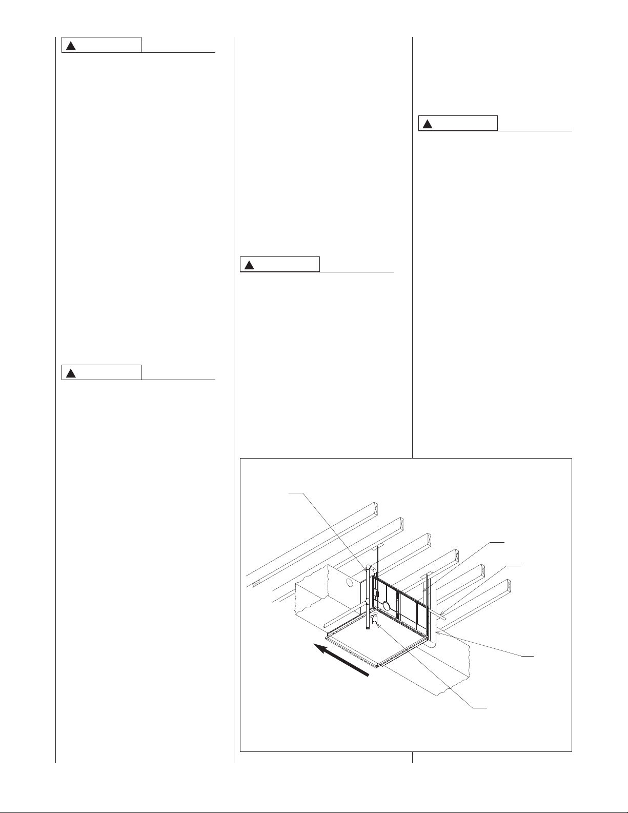
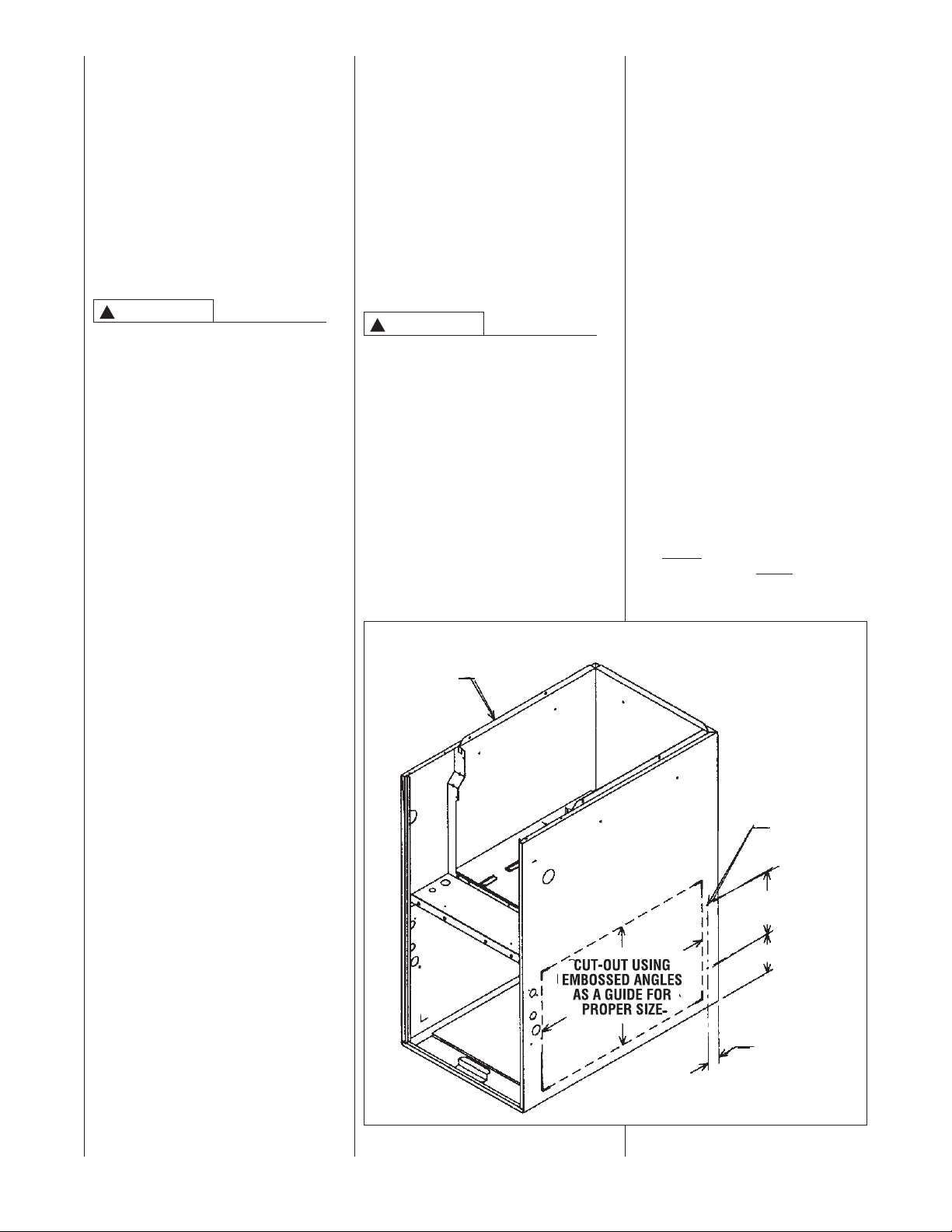
2. Open the return air compartment.
WARNING
!
UPFLOW FURNACE: A SOLID METAL
BASE PLATE MUST REMAIN IN THE
FURNACE BOTTOM WHEN USING
SIDE AIR RETURN. FAILURE TO
INSTALL A BASE PLATE COULD
CAUSE THE PRODUCTS OF
COMBUSTION TO CIRCULATE INTO
THE LIVING SPACE AND CREATE
POTENTIALLY HAZARDOUS
CONDITIONS, INCLUDING CARBON
MONOXIDE POISONING OR DEATH.
FOR BOTTOM RETURN, REMOVE
SOLID METAL BASE PLATE.
a. Cut an opening in the side. The
opening should be cut the full
width and height of the knockouts
on the unit. See Figure 8.
FIGURE 8
UPFLOW CUTOUT AND DRILL INFORMATION
NOTE: Where the maximum air flow
is 1800 CFM or more, both sides or 1
side and the bottom must be used for
return air.
3. Connect the return duct or return
air cabinet to the unit. Make the
onnection air tight to prevent
c
entraining combustion gases
from an adjacent fuel-burning
appliance.
4. Be sure to have adequate space
or the unit filter.
f
NOTE: DO NOT take return air
from bathrooms, kitchens,
furnace rooms, garages, utility or
laundry rooms, or cold areas.
NOTE: DO NOT use a rear air
return.
5. If summer air conditioning is
desired, position the indoor coil
on the supply-air side of the unit.
Insure that no air can bypass this
coil.
6. Connect the supply air plenum to
the furnace plenum opening.
IMPORTANT: If a flexible duct
connector must be used, it
MUST
be rated for a minimum
temperature of 250°F
continuous.
.
1313
OWNFLOW UNITS
D
1. Position the unit to minimize long
runs of duct or runs of duct with
many turns and elbows.
2. If summer air conditioning is
desired, position the indoor coil
on the supply-air side of the unit.
Insure that no air can bypass this
coil.
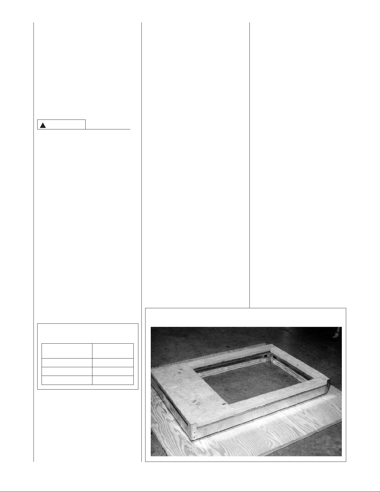
3. If installing on a combustible floor
and not using an air conditioning
plenum, install the special non-
combustible floor base. See
Table 1 and Figure 9.
WARNING
!
THE DOWNFLOW FURNACE
DESIGN IS CERTIFIED FOR
INSTALLATION ON A NONCOMBUSTIBLE FLOOR. USE THE
SPECIAL BASE SPECIFIED ON THE
FURNACE CLEARANCE LABEL.
FAILURE TO INSTALL THE
SPECIAL BASE MAY RESULT IN
FIRE, PROPERTY DAMAGE,
PERSONAL INJURY OR DEATH.
THIS SPECIAL BASE IS SHIPPED
FROM THE FACTORY AS AN
ACCESSORY.
4. Connect the furnace to the
supply air plenum.
5. Connect the return air ducting to
the return air opening at the top
of the unit. Make the connection
air tight to prevent entraining
combustion gases from an
adjacent fuel-burning appliance.
NOTE: In downflow
configuration, return air cut out is
not permitted.
6. Be sure to have adequate space
for the unit filter.
NOTE: DO NOT take return air
from bathrooms, kitchens, furnace
rooms, garages, utility or laundry
rooms, or cold areas.
HORIZONTAL UNIT
IMPORTANT: THIS FURNACE MAY
ONLY BE INSTALLED SO AS WHEN
ACING THE FRONT OF THE
F
FURNACE, SUPPLY AIR IS
DISCHARGED ON THE LEFT HAND
SIDE.
1. Position the unit to minimize long
uns of duct or runs of duct with
r
many turns and elbows.
2. If summer air conditioning is
desired, position the indoor coil on
the supply air side of the unit.
Insure that no air can bypass this
coil.
3. Connect the furnace to the supply
air plenum.
4. Connect the return air ducting to
the return air opening at the right
end of the unit. Make the
connection air tight to prevent
pulling combustion gases from an
adjacent fuel-burning appliance.
NOTE: In horizontal configuration,
return air cut out is not permitted.
5. Be sure to have adequate space
for the unit filter.
NOTE: DO NOT take return air
from bathrooms, kitchens, furnace
rooms, garages, utility or laundry
rooms, or cold areas.
TABLE 1
NON-COMBUSTIBLE FLOOR BASES
Floor Base Size
No. Cabinet
(-)XGC-B17 17
(-)XGC-B21 21
(-)XGC-B24 24
14
FIGURE 9
NON-COMBUSTIBLE FLOOR BASE
VENTING AND COMBUSTION AIR PIPING
EQUIREMENT THAT VENT
GENERAL INFORMATION
WARNING
!
READ AND FOLLOW ALL
INSTRUCTIONS IN THIS SECTION.
FAILURE TO PROPERLY VENT
THIS FURNACE CAN CAUSE
CARBON MONOXIDE POISONING
R AN EXPLOSION OR FIRE,
O
RESULTING IN PROPERTY
DAMAGE, PERSONAL INJURY
OR DEATH.
This furnace removes both sensible
and latent heat from the combustion
flue gases. Removal of latent heat
results in condensation of flue gas
water vapor. This condensed water
vapor drains from the secondary heat
exchanger and out of the unit into a
drain trap.
When installed as a non-direct vent
furnace, only exhaust piping is
required and inside combustion air
may be used. Refer to section on
COMBUSTION & VENTILATION AIR
“
FOR FURNACE INSTALLATIONS.”
Direct vent installations require a
dedicated combustion air and venting
system. All air for combustion is taken
from the outside atmosphere and all
combustion products are discharged
to the outdoors.
The combustion air and vent pipe
fittings must conform to American
National Standards Institute (ANSI)
and American Society for Testing
Materials (ASTM) standards
D1785 (Schedule 40 PVC), D2665
(PVC-DWV), D2241 (SDR-21 and
SDR26-26 PVC), D2661 (ABS-DWV)
or F628 (Schedule 40 ABS-DWV).
WARNING
!
IN CANADA, PRODUCTS
CERTIFIED FOR INSTALLATION
AND INTENDED TO BE VENTED
WITH PLASTIC VENT SYSTEMS
(PVC, CPVC) MUST USE VENT
SYSTEMS THAT ARE CERTIFIED
TO THE STANDARD FOR TYPE BH
GAS VENTING SYSTEMS, ULC
S636.
THE COMPONENTS OF THE
CERTIFIED MATERIAL MUST NOT
BE INTERCHANGED WITH OTHER
VENT SYSTEMS OR UNLISTED
PIPE/FITTINGS.
PLASTIC COMPONENTS AND
SPECIFIED PRIMERS AND GLUES
OF THE CERTIFIED SYSTEM MUST
BE FROM A SINGLE SYSTEM
MANUFACTURER AND NOT
INTERMIXED WITH OTHER
SYSTEM MANUFACTURER’S
PARTS.
NOTE: INLET AIR PIPING IS NOT
CONSIDERED TO BE A PART OF
THE “VENTING SYSTEM”. THE
R
ATERIAL BE CERTIFIED TO ULC
M
636 DOES NOT APPLY TO INLET
S
IR PIPING. VENT TERMINATIONS
A
ND CONCENTRIC TERMINATIONS
A
UST BE APPROVED BY THE
M
ANUFACTURER AND CERTIFIED
M
LC-636.
U
MPORTANT: The plastic combustion
I
air and venting components are of
Schedule 40 PVC. If using ABS
piping, ensure that the solvent
cement is compatible for joining PVC
to ABS components or use a
mechanical connection that can
withstand the vent temperatures and
are corrosion resistant.
NOTE: Schedule 40 ABS-DWV pipe
and fittings may be used as an
alternate to PVC pipe for the
combustion air inlet and vent pipes.
NOTE: Cellular core PVC is also
approved for use. It must be schedule
40PVC-DWV cellular pipe for nonpressure applications and
manufactured under ASTM F-891.
NOTE: With the furnace correctly
vented, the inducer will move
approximately 25 cfm per 100,000
Btu’s.
IMPORTANT: No part of the
combustion air and vent pipes may
run under ground.
OVERTEMPERATURE
SAFETY SWITCHES
Furnaces are equipped with safety
switches in the control compartment
to protect against overtemperature
conditions caused by inadequate
combustion air supply. The switches
are located in the burner
compartment. If a switch is tripped it
must be manually reset.
WARNING
!
DO NOT JUMPER THESE
DEVICES! IF ONE OF THESE
SWITCHES SHOULD TRIP, A
QUALIFIED INSTALLER, SERVICE
AGENCY OR THE GAS SUPPLIER
MUST BE CALLED TO CHECK
AND/OR CORRECT FOR
ADEQUATE COMBUSTION AIR
SUPPLY. DO NOT RESET THE
SWITCHES WITHOUT TAKING
CORRECTIVE ACTION TO ASSURE
THAT AN ADEQUATE SUPPLY OF
COMBUSTION AIR IS MAINTAINED
UNDER ALL CONDITIONS OF
OPERATION. FAILURE TO DO SO
CAN RESULT IN CARBON
MONOXIDE POISONING OR
DEATH. IF THIS UNIT IS MOUNTED
IN A CLOSET, THE DOOR MUST BE
CLOSED WHEN MAKING THIS
CHECK.
REPLACE THESE SWITCHES
ONLY WITH THE IDENTICAL
REPLACEMENT PART.
EXISTING VENT SYSTEMS
When the installation of this furnace
replaces an existing furnace that is
removed from a vent system serving
ther appliances, the vent system is
o
likely to be too large to properly vent
the remaining attached appliances.
he following steps should be
T
followed with each appliance
remaining connected to the original
common vent system. Place the
appliance to be tested in operation,
while the other appliances remaining
connected to the common vent
system are not in operation. Test the
operation of each appliance
individually by the following method.
1. Permanently seal any unused
openings in the common venting
system.
2. Visually inspect the venting
system for proper size and
horizontal pitch and determine
that there is no blockage,
restriction, leakage, corrosion or
other deficiencies which could
cause an unsafe condition.
3. If practical, close all building
doors, windows and all doors
between the space where the
appliances remaining connected
to the common venting system
are located.
Turn on clothes dryers and any
appliance not connected to the
common venting system. Turn on
any exhaust fans, such as range
hoods and bathroom exhausts,
so they will operate at maximum
speed. Do not operate a summer
exhaust fan. Close fireplace
dampers.
4. Follow the lighting instructions.
Place the appliance being
inspected into operation. Adjust
the thermostat so the appliance
will operate continuously.
5. Test for spillage at the draft hood
relief opening after 5 minutes of
main burner operation. Use the
flame of a match or candle, or
smoke from a cigarette, cigar
or pipe.
15
6. After it has been determined that
each appliance that remains
connected to the common
venting system properly vents
(when tested as outlined above),
return doors, windows, exhaust
fans, fireplace dampers and any
other gas-burning appliance to
their previous conditions of use.
7. If improper venting is observed
during any of the above tests, the
common venting system must be
resized.
When the furnace is installed in the
same space with other gas
appliances such as a water heater, be
sure there is an adequate supply of
ombustion and ventilation air for the
c
other appliances. Do not delete or
reduce the combustion air supply
required by the other gas appliances
in this space. See Z223.1, National
Fuel Gas Code (NFPA54) for
determining the combustion air
requirements for gas appliances. An
unconfined space must have at least
50 cubic feet (volume) for each
1,000 BTUH of the total input of all
appliances in the space. If the open
space containing the appliances is in
a building with tight construction
(contemporary construction), outside
air may still be required for the
appliances to burn and vent properly.
Outside air openings should be sized
the same as for a confined space.
IMPORTANT: Only the current vent
instructions apply. All 90 Plus Gas
Furnaces cannot be common vented.
JOINING PIPE AND
FITTINGS
WARNING
!
PVC SOLVENT CEMENTS AND
PRIMERS ARE HIGHLY
FLAMMABLE. PROVIDE
ADEQUATE VENTILATION AND DO
NOT ASSEMBLE NEAR HEAT
OURCE OR AN OPEN FLAME. DO
S
NOT SMOKE. AVOID SKIN OR EYE
CONTACT. OBSERVE ALL
CAUTIONS AND WARNINGS
PRINTED ON MATERIAL
CONTAINERS. FAILURE TO
FOLLOW THESE GUIDELINES MAY
RESULT IN FIRE, EXPLOSION OR
ASPHYXIATION CAUSING
PERSONAL INJURY OR DEATH.
All pipe, fittings, solvent cement,
primers and procedures must
conform to American National
Standard Institute and American
Society for Testing and Materials
(ANSI/ASTM) standards as shown
below:
CEMENTING JOINTS
Properly seal all joints in the PVC
vent using the following materials and
procedures.
PVC CLEANER-PRIMER AND
PVC MEDIUM-BODY SOLVENT
CEMENT
IMPORTANT: After cutting pipe,
remove all ragged edges and burrs.
This is important to prevent reduction
in pressure drop throughout the
system.
1. Cut pipe end square. Chamfer
edge of pipe. Clean fitting socket
and pipe joint area of all dirt,
grease and moisture.
2. After checking pipe and socket
or proper fit, wipe socket and
f
pipe with cleaner-primer. Apply
a liberal coat of primer to inside
surface of socket and outside of
pipe. Read instructions included
with the primer for proper
application.
3. Apply a thin coat of cement
evenly in the socket. Quickly
apply a heavy coat of cement to
the pipe end and insert pipe into
fitting with a slight twisting
ovement until it bottoms out.
m
NOTE: Cement must be fluid; if
not, recoat.
4. Hold the pipe in the fitting for 30
seconds to prevent the tapered
socket from pushing the pipe out
of the fitting.
5. Wipe all excess cement from the
joint with a rag. Allow 15 minutes
before handling. Cure time varies
according to fit, temperature and
humidity.
NOTE: Stir the solvent cement
frequently while using. Use a natural
bristle brush or the dauber supplied
with the can. The proper brush size is
one inch.
IMPORTANT: For Proper Installation
DO NOT use solvent cement that
has become curdled, lumpy or
thickened.
DO NOT thin. Observe shelf
precautions printed on containers.
For application below 32°F, use only
low-temperature-type solvent
cement.
16
PIPE & FITTING MATERIAL
Schedule 40 PVC (Pipe) D1785
Schedule 40 PVC (Cellular Core Pipe) F891
Schedule 40 PVC (Fittings) D2466
SDR-21PVC (Pipe) D2241
SDR-26 PVC (Pipe) D2241
Schedule 40 ABS Cellular Core DWV (Pipe) F628
Schedule 40 ABS (Pipe) D1527
Schedule 40 ABS (Fittings) D2468
ABS-DWV (Drain Waste & Vent)
(Pipe & Fittings)
PVC-DWV (Drain Waste & Vent)
(Pipe & Fittings)
ASTM
SPECIFICATION
D2661
D2665
COMBUSTION AND VENTILATION AIR
NON-DIRECT
erchloroethylene)
FURNACE INSTALLATIONS
WARNING
!
THE FURNACE AND ANY OTHER
UEL-BURNING APPLIANCE MUST
F
BE PROVIDED WITH ENOUGH
FRESH AIR FOR PROPER
COMBUSTION AND VENTILATION
OF THE FLUE GASES. MOST
HOMES WILL REQUIRE THAT
OUTSIDE AIR BE SUPPLIED INTO
THE FURNACE AREA. FAILURE TO
DO SO CAN CAUSE PERSONAL
INJURY OR DEATH FROM
CARBON MONOXIDE POISONING.
Adequate facilities for providing air for
combustion and ventilation must be
provided in accordance with section
5.3, “Air for Combustion and
Ventilation” of the National Fuel Gas
Code, ANSI Z223.1 (latest edition) or
applicable provisions for the local
building codes, and not obstructed so
as to prevent the flow of air to the
furnace.
IMPORTANT: Air for combustion and
ventilation must not come from a
corrosive atmosphere. Any failure
due to corrosive elements in the
atmosphere is excluded from
warranty coverage.
The following types of installation
(but not limited to the following) will
require OUTDOOR AIR for
combustion, due to chemical
exposures:
• Commercial buildings
• Buildings with indoor pools
• Furnaces installed in laundry rooms
• Furnaces in hobby or craft rooms
• Furnaces installed near chemical
storage areas.
Exposure to the following substances
in the combustion air supply (but not
limited to the following) will also
require OUTDOOR AIR for
combustion:
• Permanent wave solutions
• Chlorinated waxes and cleaners
• Chlorine-based swimming pool
chemicals
• Water softening chemicals
• De-icing salts or chemicals
• Carbon tetrachloride
• Halogen type refrigerants
• Cleaning solvents (such as
p
• Printing inks, paint removers,
varnishes, etc.
• Hydrochloric acid
• Cements and glues
• Antistatic fabric softeners for
lothes dryers
c
• Masonry curing and acid washing
materials
Combustion air must be free of acidforming chemicals such as sulphur,
fluorine and chlorine. These elements
are found in aerosol sprays,
detergents, bleaches, cleaning
solvents, air fresheners, paint and
varnish removers, refrigerants and
many other commercial and
household products. When burned in
a gas flame, vapors from these
products form acid compounds. The
acid compounds increase the dew
point temperature of the flue products
and are highly corrosive after they
condense.
WARNING
!
ALL FURNACE INSTALLATIONS
MUST COMPLY WITH THE
NATIONAL FUEL GAS CODE AND
LOCAL CODES TO PROVIDE
ADEQUATE COMBUSTION AND
VENTILATION AIR FOR THE
FURNACE. FAILURE TO DO SO
CAN RESULT IN EXPLOSION, FIRE,
PROPERTY DAMAGE, CARBON
MONOXIDE POISONING,
PERSONAL INJURY OR DEATH.
Combustion air requirements are
determined by whether the furnace is
in an open (unconfined) area or in a
confined space such as a closet or
small room.
EXAMPLE 1:
FURNACE LOCATED IN AN
UNCONFINED SPACE
Using indoor air for combustion.
An unconfined space must have at
least 50 cubic feet for each 1,000
BTUH of the total input for all
appliances in the space. Here are a
few examples of the room sizes
required for different inputs. The sizes
are based on 8-foot ceilings.
BTUH Minimum Sq. Feet Typical Room Size
Input With 8' Ceiling With 8' Ceiling
5,000 281 14' x 20' OR 16' x 18'
4
0,000 375 15' x 25' OR 19' x 20'
6
5,000 469 15' x 31' OR 20' x 24'
7
0,000 563 20’ x 28’ OR 24’ x 24’
9
105,000 657 20' x 33' OR 26' x 25'
120,000 750 25' x 30' OR 24' x 32'
If the open space containing the
furnace is in a building with tight
construction, outside air may still be
required for the furnace to operate
and vent properly. Outside air
openings should be sized the same
as for a confined space.
EXAMPLE 2:
FURNACE LOCATED IN A
CONFINED SPACE
A confined space (any space smaller
than shown above as “unconfined”)
must have openings into the space
which are located in accordance with
the requirements set forth in the
following subsections A and B. Size
the openings by how they are
connected to the heated area or to
the outside,
and by the input of all appliances in
the space.
If confined space is within a building
with tight construction, combustion air
must be taken from outdoors or area
freely communicating with the
outdoors.
A. USING INDOOR AIR FOR
COMBUSTION
IMPORTANT: Air should not be
taken from a heated space with a
fireplace, exhaust fan or other
device that may produce a
negative pressure.
If combustion air is taken from the
heated area, the openings must
each have at least 100 square
inches of free area. Each opening
must have at least one square inch
of free area for each 1,000 BTUH
of total input in the space. Here
are some examples of typical
openings required.
BTUH Free Area
17
nput Each Opening
I
5,000 100 square inches
4
0,000 100 square inches
6
5,000 100 square inches
7
90,000 100 square inches
105,000 105 square inches
120,000 120 square inches
IGURE 10
F
AIR FROM HEATED SPACE
B. USING OUTDOOR AIR FOR
COMBUSTION
MPORTANT: Do not take air from
I
an attic space that is equipped
with power ventilation.
The confined space must
communicate with the outdoors in
accordance with Methods 1 or 2.
The minimum dimension of air
openings shall not be less than 3
inches. Where ducts are used,
they shall be of the same crosssectional area as the free area of
the openings to which they
connect.
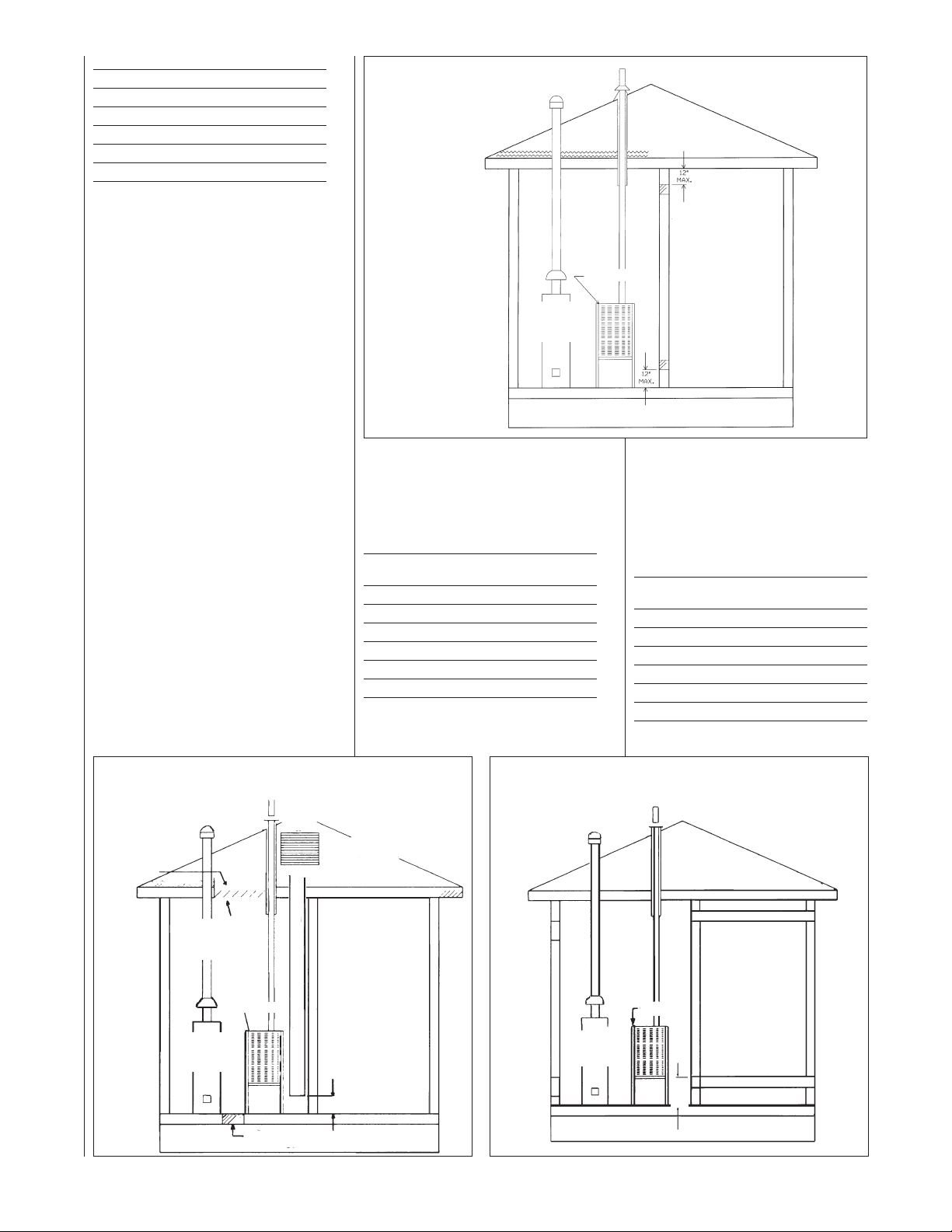
Method 1
Two permanent openings, one
located within 12 inches of the top
and one located within 12 inches
of the bottom of the enclosure,
shall be provided. The openings
shall communicate directly, or by
ducts, with the outdoors or spaces
(crawl or attic) that freely
communicate with the outdoors.
a. Where directly communicating
with the outdoors or where
communicating to the outdoors
AS
G
WATER
HEATER
through vertical ducts as shown in
Figure 11, each opening shall
have a minimum free area of 1
square inch for each 4,000 BTUH
of total appliance input rating in the
enclosure.
BTUH Free Area Round Pipe
Input Each Opening Size
45,000 11.25 square inches 4"
60,000 15.00 square inches 5"
75,000 18.75 square inches 5"
90,000 22.50 square inches 6"
105,000 26.25 square inches 6"
120,000 30.00 square inches 6"
b. Where communicating with
URNACE
F
NOTE:
ACH OPENING SHALL
E
HAVE A FREE AREA OF
NOT LESS THAN ONE
QUARE INCH PER 1,000
S
BTU PER H0UR OF THE
TOTAL INPUT RATING OF
LL EQUIPMENT IN THE
A
ENCLOSURE, BUT NOT
LESS THAN 100 SQUARE
NCHES.
I
outdoors through horizontal ducts,
each opening shall have a
minimum free area of 1 square
inch for each 2,000 BTUH of total
input rating of all equipment in the
enclosure (see Figure 12).
Here are some typical sizes:
BTUH Free Area Round Pipe
Input Each Opening Size
45,000 22.50 square inches 6"
60,000 30.00 square inches 6"
75,000 37.50 square inches 7"
90,000 45.00 square inches 8"
105,000 52.50 square inches 8"
120,000 60.00 square inches 9"
Method 2 (not shown)
FIGURE 11
AIR FROM ATTIC/CRAWL SPACE
OUTLET AIR
IN ATTIC
MUST BE
ABOVE
INSULATION
1 SQ. INCH PER
4000 BTUH
OUTLET AIR
GAS
WATER
HEATER
18
GABLE
VENT
FURNACE
OPTIONAL1 SQ. INCH PER 4000 BTUH INLET AIR
1 SQ. INCH PER
4000 BTUH INLET AIR
VENTILATED
ATTIC GABLE OR
SOFFIT VENTS
12" MAX.
FIGURE 12
OUTSIDE AIR USING A HORIZONTAL DUCT
OUTLET AIR 1 SQ. INCH
FURNACE
GAS
WATER
HEATER
INLET AIR 1 SQ. INCH
12"
MAX.
PER 2000 BTUH
PER 2000 BTUH
One permanent opening, located
within 12 inches of the top of the
enclosure, shall be permitted
where the equipment has
clearances of at least 1 inch from
the sides and back and 6 inches
from the front of the appliance.
The opening shall directly
communicate with the outdoors or
communicate through a vertical or
orizontal duct to the outdoors or
h
spaces (crawl or attic) that freely
communicate with the outdoors,
and shall have a minimum free
area of:
. 1 square inch for each 3,000
a
BTUH of the total input rating of all
equipment located in the enclosure
and
FIGURE 13
COMBUSTION AIR FITTING
TUH Free Area Round Pipe
B
nput Each Opening Size
I
5,000 15.00 square inches 4"
4
0,000 16.67 square inches 5"
6
5,000 25.00 square inches 6"
7
90,000 30.00 square inches 6"
105,000 35.00 square inches 7"
120,000 40.00 square inches 7"
b. Not less than the sum of the
areas of all vent connectors in the
confined space.
If unit is installed where there is an
exhaust fan, sufficient ventilation
must be provided to prevent the
exhaust fan from creating a negative
pressure.
Combustion air openings must not be
restricted in any manner.
CONSULT LOCAL CODES FOR
SPECIAL REQUIREMENTS.
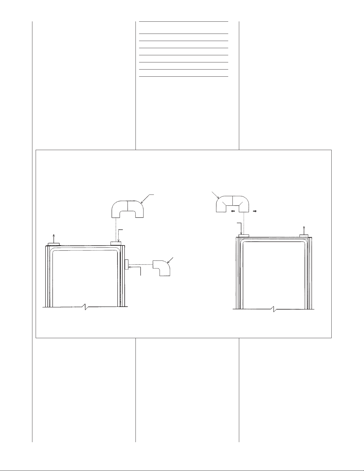
CONNECTION TO
FURNACE
IMPORTANT: When indoor
combustion air is used, the inlet air
pening at the furnace must be
o
protected from accidental blockage.
(See Figure 13).
UPFLOW
TTACH DOUBLE ELBOW TO TOP INLET
A
IR OPENING OR 90° ELBOW TO SIDE
A
NLET AIR OPENING TO PREVENT
I
CCIDENTALBLOCKAGE OF INTAKE
A
PENING. PLUG OPENING NOT USED.
O
XHAUST
E
OP
T
OPTION
I337
SIDE
OPTION
2" PVC
OUBLE
D
ELBOW
2" PVC ELBOW
" PVC
DOWNFLOW/HORIZONTAL
2
DOUBLE
ELBOW*
COMBUSTION AIR
*NOTE: WHEN FURNACE IS INSTALLED IN A HORIZONTAL POSITION
ONLY ONE 90° ELBOW IS REQUIRED. INSTALLTHE ELBOW SO THE
OPEN END IS POINTED DOWNWARD.
TTACH DOUBLE ELBOW TO INTAKE AIR
A
OLLAR AND SECURE WITH TWO SHEET
C
ETAL SCREWS TO PREVENT ACCIDENTAL
M
LOCKAGE OF INTAKE AIR OPENING.
B
REDRILL FOR SCREWS.
P
EXHAUST
I336
19
VENT PIPE INSTALLATION
NON-DIRECT VENT
INSTALLATION
GUIDELINES
IMPORTANT: Failure to correctly follow
all venting guidelines may result in
rratic furnace operation, freeze-up of
e
combustion air or exhaust air piping or
sooting of the furnace.
ll exhaust piping must be installed in
A
compliance with Part 7, “Venting of
Equipment,” of the latest edition of the
National Fuel Gas Code NPFA54/ ANSI
Z223.1-, local codes or ordinances and
these instructions.
1. Vertical piping is preferred.
2. All horizontal piping must slope
upward a minimum of
foot of run so that condensate drains
toward the furnace.
3. All horizontal runs must be
supported at least every 4 feet. No
sags or dips are permitted.
4. IMPORTANT: Do not common vent
with any other appliance. Do not
install in the same chase or chimney
with a metal or high temperature
plastic pipe from another gas or fuelburning appliance unless the
required minimum clearances to
combustibles are maintained
between the pvc pipe and other
pipes.
5. All vent runs through unconditioned
spaces where below-freezing
temperatures are expected should
be insulated with 1-in. thick,
medium-density, foil-faced
fiberglass. An equivalent “arm-aflex” or “rub-a-tex” insulation may
also be used as long as there is no
heat tape applied to the vent pipe.
For horizontal runs where water may
collect, wrap the vent pipe with selfregulating 3 or 5 watt heat tape. The
heat tape must be U.L. listed and
installed per the manufacturer’s
instructions.
6. The minimum vent pipe length is
5 feet.
7. Extend the exhaust pipe a minimum
of 18” from the cabinet before turning
vent.
8. Vent cannot be ran underground.
FIGURE 14
TEE TERMINAL – FOR STANDARD
HORIZONTAL NON-DIRECT
INSTALLATION
VENT
1
/4 inch per
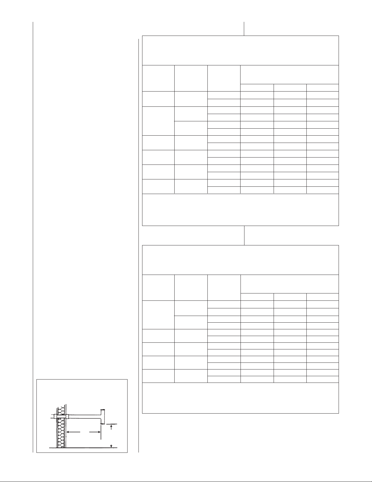
TABLE 2
UPFLOW UNITS
FOR NON-DIRECT VENT APPLICATIONS - AIR FOR COMBUSTION
PROVIDED FROM INDOORS
MAXIMUM ALLOWABLE LENGTH IN FEET OF EACH EXHAUST PIPE AND INTAKE PIPE
NUMBERS OF ELBOWS
FURNACE
INPUT
45,000
0,000
6
75,000
90,000
05,000 3”
1
120,000 3”
NOTES:
1. *N.A. - NOT APPLICABLE.
2. MAXIMUM OF 6 ELBOWS MAY BE USED. DO NOT COUNT ELBOWS REQUIRED FOR
ALTERNATE TERMINATION. USE ONLY MEDIUM OR LONG SWEEP ELBOWS.
3. A 45 OR 22.5 DEGREE ELBOW IS CONSIDERED ONE ELBOW.
4. NO SCREENS MAY BE USED TO COVER EXHAUST.
*A = 17-1/2” CABINET WIDTH B = 21) CABINET WIDTH
PIPE
SIZE
2”
2
3
3
3”
ERMINATION
T
1-2 3-4 5-6
Standard 60 55 50
Alternate 55 50 45
”
”
”
Standard 30 25 20
Alternate 25 20 15
tandard 120 120 115
S
lternate 120 120 110
A
tandard 45 40 NA
S
Alternate 45 45 NA
Standard 90 85 75
Alternate 60 50 45
Standard 45 40 NA
lternate NA NA NA
A
tandard 70 65 55
S
lternate 40 30 25
A
45° OR 90°
edium / Long Radius ONLY
M
TABLE 3
DOWNFLOW/HORIZONTAL UNITS
FOR NON-DIRECT VENT APPLICATIONS - AIR FOR COMBUSTION
PROVIDED FROM INDOORS
MAXIMUM ALLOWABLE LENGTH IN FEET OF EACH EXHAUST PIPE AND INTAKE PIPE
NUMBERS OF ELBOWS
FURNACE
INPUT
60,000
75,000
90,000 3”
105,000 3”
120,000 3”
NOTES:
1. *N.R. - NOT RECOMMENDED.
2. MAXIMUM OF 6 - 90 DEGREE ELBOWS MAY BE USED. DO NOT COUNT ELBOWS REQUIRED FOR
ALTERNATE TERMINATION. USE ONLY MEDIUM OR LONG SWEEP ELBOWS.
3. A 45 OR 22.5 DEGREE ELBOW IS CONSIDERED ONE ELBOW.
4. NO SCREENS MAY BE USED TO COVER EXHAUST.
*A = 17-1/2” CABINET WIDTH B = 21” CABINET WIDTH
PIPE
SIZE
2”
3”
3”
TERMINATION
1-2 3-4 5-6
Standard 40 35 30
Alternate 30 25 20
Standard 120 120 120
Alternate 110 105 100
Standard 120 120 120
Alternate 100 95 85
Standard 110 105 95
Alternate 50 40 35
Standard 65 60 55
Alternate 50 40 35
Standard 40 35 30
Alternate 40 35 30
45° OR 90°
Medium / Long Radius ONLY
20
12"
12" MIN. ABOVE
GRADE OR
SNOW LEVEL
ELEVATED SINGLE PIPE ALTERNATE TEE TERMINATION
See Figure 15. The tee termination may be elevated up to 24 inches above the
wall penetration if required for anticipated snow levels. Use 2 long-sweep, 2-in.
PVC elbows and 2-in. PVC pipe, attaching the tee so it is 12 inches from the wall.
 Loading...