

Page 1
RGTC
Parts List
29-January-2016
This parts list is current as of the above revision date.
See http://www.rheempartslists.net/92-42800-RGTC.pdf for the current revision.
95% Gas Furnaces
Page 2

Table of Contents
Model Explanation.... ..... ..... ..... ..... .... . .... . .... . .... ..... ..... ..... ..... .... . .... . .... . .... ..... ..... ..... ..... .... . .... . ... Page 3
Parts Numbers
Panels - Miscellaneous (1).... ..... ..... ..... .... . .... . .... . .... ..... ..... ..... ..... .... . .... . .... . .... ..... ..... Page4
Panels - Miscellaneous (2).... ..... ..... ..... .... . .... . .... . .... ..... ..... ..... ..... .... . .... . .... . .... ..... ..... Page5
Electrical Group . ..... ..... ..... ..... ..... .... . .... . .... ..... ..... ..... ..... ..... .... . .... . .... ..... ..... ..... ... Page 6
Blower Group... ..... ..... ..... ..... .... . .... . .... . .... ..... ..... ..... ..... ..... .... . .... . .... ..... ..... ..... .... Page 6
Heat Exchanger-Burner Group.... ..... ..... ..... .... . .... . .... . .... ..... ..... ..... ..... ..... .... . .... . .... ..... . Page 7
Gas Controls ... ..... ..... ..... ..... .... . .... . .... . .... ..... ..... ..... ..... .... . .... . .... . .... ..... ..... ..... .... Page 8
Orifice Selection Chart.... ..... ..... ..... .... . .... . .... . .... ..... ..... ..... ..... ..... .... . .... . .... ..... ..... .... Page 9
Drawings/Photographs
Exploded View .... ..... ..... ..... ..... .... . .... . .... . .... ..... ..... ..... ..... .... . .... . .... . .... ..... ..... ..... Page 10
Horizontal Installation Parts.. ..... ..... ..... ..... .... . .... . .... . .... ..... ..... ..... ..... .... . .... . .... . .... ..... Page 11
Blower Assembly ..... ..... ..... ..... .... . .... . .... . .... ..... ..... ..... ..... ..... .... . .... . .... ..... ..... ..... .. Page 12
Burner Assembly ... ..... ..... ..... ..... .... . .... . .... . .... ..... ..... ..... ..... .... . .... . .... . .... ..... ..... .... Page13
Base Pan Gasket.... ..... ..... ..... ..... .... . .... . .... . .... ..... ..... ..... ..... .... . .... . .... . .... ..... ..... ... Page 14
Notes/Disclaimer . ..... ..... ..... ..... .... . .... . .... . .... ..... ..... ..... ..... .... . .... . .... . .... ..... ..... ..... ..... ..... .... . .... . . Page 15
Page 2 of 15
29-January-2016
92-42800-RGTC
Page 3

MODEL NUMBER EXPLANATION
R G T C - 0 4 E M A E S
(1) (2) (3) (4) (5) (6) (7) (8) (9)
(1) TRADEBRAND IDENTIFICATION (6) BLOWER DESIGNATION
M = 11 x 7
(2) MODEL R = 11 x 10
G = Gas Furnace Y = 12 x 7
Z = 12 x 11
(3) TYPE
T = Downflow/Horizontal Condensing (7) VARIATIONS
A = Standard
(4) DESIGN SERIES B = Wide Cabinet
(5) HEATING INPUT DESIGNATION (8) AIRFLOW
04 = 45,000 BTU/HR E = 1100 - 1300 CFM
06 = 60,000 BTU/HR G = 1500 - 1700 CFM
07 = 75,000 BTU/HR J = 1900 - 2100 CFM
09 = 90,000 BTU/HR
10 = 105,000 BTU/HR (9) FUEL DESIGNATION
S = U.S. & Canada Furnace - Natural Gas
E = Electric
SERIAL NUMBER EXPLANATION
H L 5 D 7 0 7 F 3 1 9 5 9 9 9 9
(1) (2) (3) (4) (5) (6) (7) (8) (9) (10)
(1) GAS CONTROL (6) MOTOR HORSEPOWER
(2) LIMIT CONTROL (7) PLANT
F = Fort Smith, AR
(3) BLOWER
(8) WEEK
(4) HEATING ELEMENT
(9) YEAR
(5) SPECIAL AREA REQUIREMENT
(10) PRODUCTION NUMBER
Page 3 of 15
29-January-2016
92-42800-RGTC
Page 4
MODEL
No. Notes
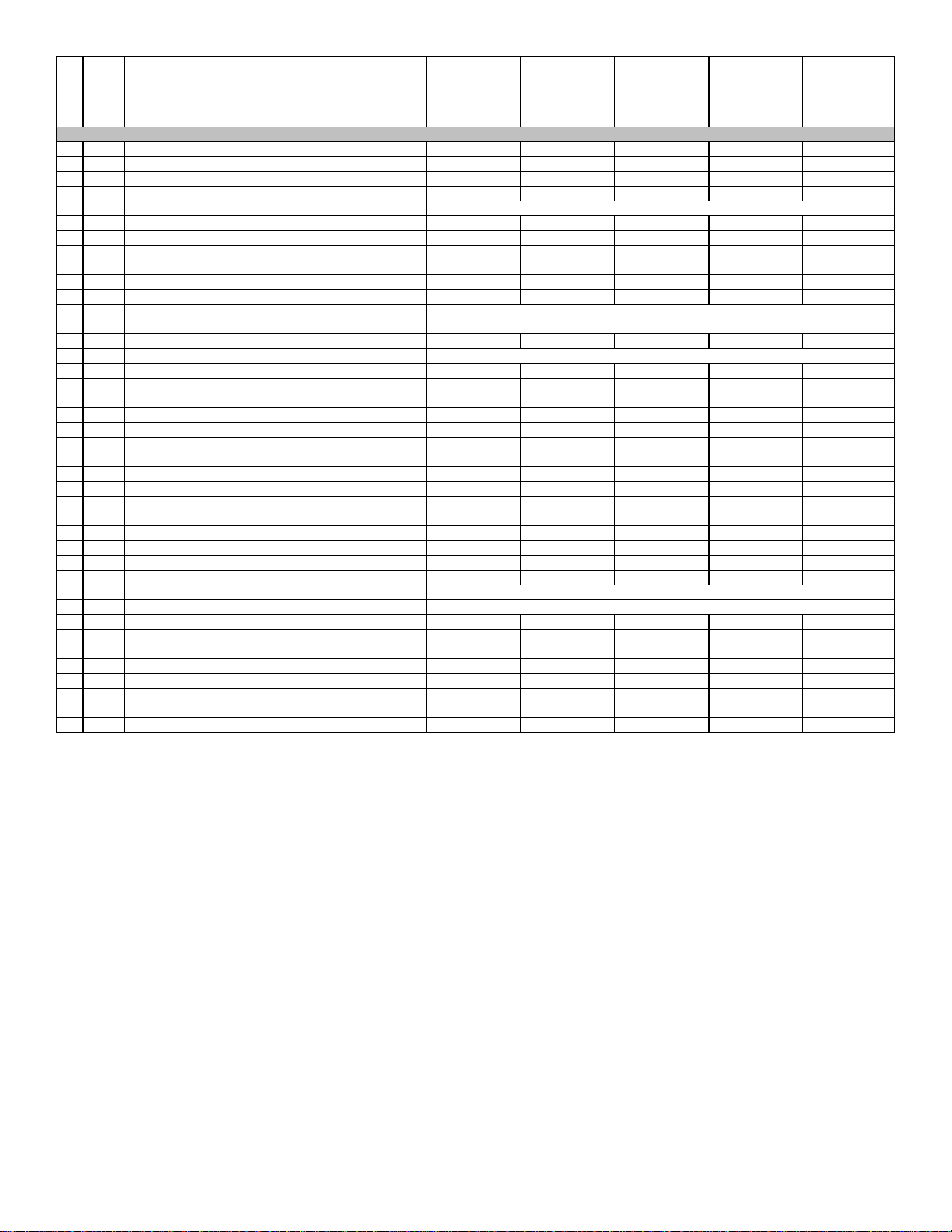
1 Blower/Filter Door (Neutra Green) AS-61908-03 AS-61908-03 AS-61909-03 AS-61909-03 AS-61910-03
1 Blower/Filter Door (Granite/Steel Gray) AS-61908-04 AS-61908-04 AS-61909-04 AS-61909-04 AS-61910-04
2 Burner Compartment Door (Neutra Green) AS-61905-01 AS-61905-01 AS-61906-01 AS-61906-01 AS-61907-01
2 Burner Compartment Door (Granite/Steel Gray) AS-61905-03 AS-61905-03 AS-61906-02 AS-61906-02 AS-61907-02
3 InducedDraft Blower w/Gasket See Electrical Group
5 Connector/Transition 68-24047-10 68-24047-10 68-24047-11 68-24047-11 68-24047-12
6 Drain- Double Elbow 79-102881-01 79-102881-01 79-102881-01 79-102881-01 79-102881-01
7 Elbow/Trap Assembly 68-24048-01 68-24048-01 68-24048-01 68-24048-01 68-24048-01
8 Water Trap Mount Bracket AE-61841-01 AE-61841-01 AE-61841-01 AE-61841-01 AE-61841-01
9 HoseClamps (4) 64-22043-01 64-22043-01 64-22043-01 64-22043-01 64-22043-01
10 Drain - Elbow 79-102882-01 79-102882-01 79-102882-01 79-102882-01 79-102882-01
18 Limit - Main Limit (Heat Exchanger Panel) See Electrical Group
19 Heat Exchanger Assembly See Heat Exchanger Group
25 SiliconTubing- Pressure Switch AE-61737-27 AE-61737-27 AE-61737-27 AE-61737-27 AE-61737-27
26 Pressure Switch See Electrical Group
27 Plug Button - 2 in. opening 45-22980-08 45-22980-08 45-22980-08 45-22980-08 45-22980-08
28 Door Angle AS-67847-01 AS-67847-01 AS-67847-02 AS-67847-02 AS-67847-03
29 Grommet (1-5/8 in. opening) 56-22114-01 56-22114-01 56-22114-01 56-22114-01 56-22114-01
29 Grommet (2 in. opening) 56-22114-06 56-22114-06 56-22114-06 56-22114-06 56-22114-06
30 Outlet Pipe Gasket 68-24022-02 68-24022-02 68-24022-02 68-24022-02 68-24022-02
31 Outlet Pipe Assembly 68-24150-01 68-24150-01 68-24150-01 68-24150-01 68-24150-02
32 2 Jacket (See Note 2) N/A N/A N/A N/A N/A
33 Top Plate AE-67805-02 AE-67805-02 AE-67805-03 AE-67805-03 AE-67805-04
Gasket - Top Plate 68-102279-01 68-102279-01 68-102279-02 68-102279-02 68-102279-03
A Gasket - Base Pan AE-61871-01 AE-61871-01 AE-61871-02 AE-61871-02 AE-61871-03
34 Inlet Air Chase Assembly AS-67848-01 AS-67848-01 AS-67848-01 AS-67848-01 AS-67848-01
35 Inlet Air Chase Gasket 68-24022-01 68-24022-01 68-24022-01 68-24022-01 68-24022-01
36 Plug Button - 2 in. opening 45-22980-08 45-22980-08 45-22980-08 45-22980-08 45-22980-08
37 JunctionBox Cover AE-61476-02 AE-61476-02 AE-61476-02 AE-61476-02 AE-61476-02
38 JunctionBox AE-67825-01 AE-67825-01 AE-67825-01 AE-67825-01 AE-67825-01
39 Door Switch See Electrical Group
44 BlowerAssembly See Blower Group
Filter - Plastic (2) 54-22699-01 54-22699-01 54-22699-01 54-22699-01 54-22699-02
Filter Rack AE-66681-01 AE-66681-01 AE-66681-01 AE-66681-01 AE-66681-01
Touch-up Paint - Platinum (Aerosol) 523012 523012 523012 523012 523012
Touch-up Paint - Platinum (Paint Pens) 523013 523013 523013 523013 523013
Touch-up Paint - Green (Aerosol) 52-18662-48 52-18662-48 52-18662-48 52-18662-48 52-18662-48
Touch-up Paint - Green (Paint Pens) 523010 523010 523010 523010 523010
Touch-up Paint - Granite/Steel Gray (Aerosol) PD523018 PD523018 PD523018 PD523018 PD523018
Touch-up Paint - Granite/Steel Gray (PaintPens) PD523019 PD523019 PD523019 PD523019 PD523019
HEATING CAPACITY
BLOWER DESIGNATION
VARIATION
AIRFLOW
PANELS, SHEET METAL, MISCELLANEOUS
RGTC
04
M
A
E
RGTC
06
M
A
E
RGTC
07
R
B
G
RGTC
09
Z
A
J
RGTC
10
R
B
J
Page 4 of 15
29-January-2016
92-42800-RGTC
Page 5
MODEL
No. Notes
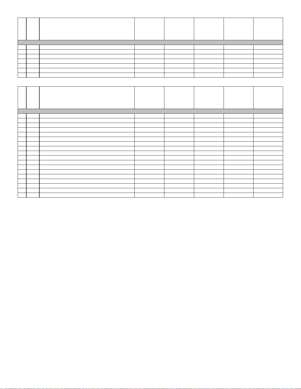
6 Drain- Double Elbow 79-102881-01
9 HoseClamps (4) 64-22043-01
10 Drain - Elbow 79-102882-01
11 Elbow (Connector/Transition - Trap) 68-24121-01
12 Trap Assembly 68-24120-02
13 Trap Gasket 68-24123-01
14 Hole Plugs (2) 45-24125-01
No. Notes
Complete Parts Bag AS-100717-03
1/2 in. PVC Pipe - 4 in. 68-22024-04
1/2 in.Tee 68-21980-02
PVCVane (2-13/32 in. x 1 in.) 68-23473-01
PVC Wind Vane(2-7/8 in. x 1 in.) 68-24049-01
DrainTube- 6-3/4 in. 68-24026-04
11 Elbow 68-24121-01
9 HoseClamp - 5/8 in. (2) 64-22043-01
12 Trap Assembly 68-24120-02
13 Trap Gasket 68-24123-01
14 Hole Plug (2) 45-24125-01
Button Plug with Recessed Type Head (2 in. hole) 45-22980-08
Vinyl Grommet - 1-5/8 in. hole (for7/8 in. OD Pipe) 56-22114-01
Nylon Plug - 7/8 in. (2) 45-22926-01
Nylon Plug - 1-1/8 in. 45-22926-02
Pipe - 24 in. 68-24085-01
Screw - #6-20 x 1/2 63-22153-04
PVCVane (3-1/2 in. x 1-3/8 in.) 68-103677-01
HEATING CAPACITY
BLOWER DESIGNATION
VARIATION
HEAT/COOL DESIGNATION
HORIZONTAL INSTALLATION PARTS
MODEL
HEATING CAPACITY
BLOWER DESIGNATION
VARIATION
AIRFLOW
RGTC
ALL
ALL
ALL
ALL
RGTC
ALL
ALL
ALL
ALL
PARTS BAG
Page 5 of 15
29-January-2016
92-42800-RGTC
Page 6

MODEL
No. Notes
3 Stk Induced Draft Blowerw/Gasket 70-24033-01 70-24033-01 70-24033-01 70-24033-01 70-24033-01
18 Stk Limit - Main Limit (Heat Exchanger Panel) 47-25350-09 47-25350-07 47-25350-05 47-25350-13 47-25350-05
26 Stk Pressure Switch 42-101956-01 42-101956-01 42-101956-11 42-101956-01 42-101956-09
39 Door Switch - Push Button 42-22692-02 42-22692-02 42-22692-02 42-22692-02 42-22692-02
49 Stk Transformer w/Fuse 46-24124-03 46-24124-03 46-24124-03 46-24124-03 46-24124-03
51 Integrated Furnace Control Board (IFC) SeeGas Controls
52 Stk Capacitor - Induced Draft Blower 43-100496-44 43-100496-44 43-100496-44 43-100496-44 43-100496-44
53 Capacitor - Blower Motor See Blower Group
54 Stk Limit - Heat Assisted ( Blower Housing) 47-22860-02 47-22860-02 47-22860-02 47-22860-02 47-22860-03
61 Stk Limit - Manual Reset (Burner Compartment)
Stk
No. Notes
44 Stk Blower Assembly (Includes items 45-48, 53) AS-61697-38 AS-61697-38 AS-61697-101 AS-61697-40 AS-61697-41
45 Motor Mount Leg (4) AE-61698-02 AE-61698-02 AE-61698-02 AE-61698-02 AE-61698-02
46 Stk Blower Motor 51-24042-01 51-24042-01 51-103243-01 51-24043-01 51-24043-01
47 Housing AS-61674-14 AS-61674-14 AS-61674-15 AS-61674-15 AS-61674-16
48 Stk Blower Wheel 70-22688-01 70-22688-01 70-20602-01 70-24041-01 70-20602-01
49 Transformer w/Fuse See Electrical Group
50 Control Mounting Plate AE-67877-01 AE-67877-01 AE-67877-01 AE-67877-01 AE-67877-01
51 Integrated Furnace Control Board (IFC) SeeGas Controls
52 Capacitor - Induced Draft Blower See Electrical Group
53 Stk Capacitor - Blower Motor 43-101666-42 43-101666-42 43-101666-43 43-101666-43 43-101666-43
54 Limit Control w/Heater See Electrical Group
HEATING CAPACITY
BLOWER DESIGNATION
VARIATION
AIRFLOW
Limit - Manual Reset (Burner Compartment) - on Center
Panel
Wiring Harness - 4 pin to 2 ring terminals/1 straight
terminal/1 strip back
Direct Spark Wiring Harness - 9 pin from board to 9 pin
and 4 pin
Twist Lock - Direct Spark Ignition Wiring Harness - 9 pin
to 8 terminals and 6 pin to 4 pin
Direct Spark Ignition Wiring Harness - 2 pin from board
to 6 pin, (3 terminals off 6 pin, 1 terminal off 2 pin) Downflow Models w/HALC
MODEL
HEATING CAPACITY
BLOWER DESIGNATION
VARIATION
AIRFLOW
RGTC
04
M
A
E
ELECTRIC GROUP
47-22861-02
(1)
47-22861-04
(2)
45-24371-41 45-24371-41 45-24371-41 45-24371-41 45-24371-41
45-24371-28 45-24371-28 45-24371-28 45-24371-28 45-24371-28
45-24393-02 45-24393-02 45-24393-02 45-24393-02 45-24393-02
45-24371-29 45-24371-29 45-24371-29 45-24371-29 45-24371-29
RGTC
04
M
A
E
BLOWER GROUP
RGTC
06
M
A
E
47-22861-02
(1)
47-22861-04
(2)
RGTC
06
M
A
E
RGTC
07
R
B
G
47-22861-02
(1)
47-22861-04
(2)
RGTC
07
R
B
G
RGTC
09
Z
A
J
47-22861-02
(2)
47-22861-04
(2)
RGTC
09
Z
A
J
RGTC
47-22861-02
47-22861-04
RGTC
10
R
B
J
(2)
(2)
10
R
B
J
Page 6 of 15
29-January-2016
92-42800-RGTC
Page 7

MODEL
No. Notes
3 Induced Draft Blowerw/Gasket See Electrical Group
18 Limit - Main Limit (Heat Exchanger Panel) See Electrical Group
19 Stk Heat Exchanger AS-67818-36 AS-67818-37 AS-67818-38 AS-67818-39 AS-67818-40
20 Baffle AE-61876-01 AE-61875-01 AE-61876-01 AE-61875-01 AE-61876-01
21 Rear Baffle AE-61878-01 AE-61878-01 AE-61878-02 AE-61878-02 AE-61878-03
22 Baffle AE-61876-02 AE-61875-02 AE-61876-02 AE-61875-02 AE-61876-02
23 Heat Exchanger Bracket AE-67846-02 AE-67846-02 AE-67846-02 AE-67846-02 AE-67846-02
24 Heat Exchanger Bracket AE-61959-01 AE-61959-01 AE-61959-01 AE-61959-01 AE-61959-01
55 Stk Burners AS-61984-03 AS-61984-04 AS-61984-05 AS-61984-06 AS-61984-07
56 Burner Support Bracket (2) AE-61808-01 AE-61808-01 AE-61808-01 AE-61808-01 AE-61808-01
57 Burner Support AE-61809-11 AE-61809-12 AE-61809-13 AE-61809-14 AE-61809-15
59 Stk Manifold(w/o Orifices) 81-24396-01 81-24396-02 81-24396-03 81-24396-04 81-24396-05
61 Limit - Manual Reset (Burner Compartment) See Electrical Group
62 Flame Sensor SeeGas Controls
63 Stk Ignitor - Direct Spark 62-24141-04 62-24141-04 62-24141-04 62-24141-04 62-24141-04
64 Burner Orifice - Natural Gas See Orifice Selection Chart
64 Burner Orifice - LP See Orifice Selection Chart
Number of Orifices (3) (4) (5) (6) (7)
65 Gas Valve See Gas Controls
Bracket - Flame Roll-out (On Center Panel AE-61600-02 AE-61600-02 AE-61600-02 AE-61600-02 AE-61600-02
Direct Spark Igniter Bracket AE-61885-02 AE-61885-02 AE-61885-02 AE-61885-02 AE-61885-02
HEATING CAPACITY
BLOWER DESIGNATION
VARIATION
AIRFLOW
HEAT EXCHANGER, BURNER / MANIFOLD
RGTC
04
M
A
E
RGTC
06
M
A
E
RGTC
07
R
B
G
RGTC
09
Z
A
J
RGTC
10
R
B
J
Page 7 of 15
29-January-2016
92-42800-RGTC
Page 8

No. Notes
51 Stk Integrated Furnace Control Board (IFC) 62-24140-04 62-24140-04
62 Stk Flame Sensor 62-23543-06 62-23543-06
63 Ignitor - Direct Spark
65 Stk GasValve - Natural Gas 60-24180-01 60-100394-03
65 Stk,1 GasValve - LP See Note 1 See Note 1
Wiring Harnesses
Stk LPConversion Kit - US FP-02 FP-02
Stk LPConversion Kit - Canada FP-02 FP-02
MODEL
GAS CODE
GAS CONTROLS
RGTC
HL
See Heat
Exchanger
Group
See Electrical
Group
RGTC
HM
See Heat
Exchanger
Group
See Electrical
Group
Page 8 of 15
29-January-2016
92-42800-RGTC
Page 9

CAUTION: Selection of the correct Natural Gas Orifice requires the following information for the specific installation:
1) Altitude in of the installation (ft.).
2) Average energy content of the Natural Gas fuel from the local supplier (BTU/cu. ft.).
For detailed information and instructions for Orifice selection, see the Gas Furnace LP Conversion Kit Index 92-21519-59 and the latest edition of the
National Fuel Gas Code Handbook, or the National Standard of Canada, Natural Gas and Propane Installation Code, CAN B149.1.
CAUTION:This information is provided for replacement purposes only. Conversion for operation at High Altitude must be done using the kit specified
on the product specification sheet for the unit.
NOTE:This Orifice sizing chart is based on 15,000 BTU/HR per burner.
NOTE: Factory installed orifices are calculated and sized based on a Natural Gas heating value of 1075 BTU/cu. ft. and an elevationof 0 - 2000 ft.
Elevation (ft.)
EnergyValue
(BTU/cu. ft.)
850 62-22175-47 62-22175-48 62-22175-48 62-22175-49 62-22175-49 62-22175-49 62-22175-50 62-22175-50
900 62-22175-48 62-22175-49 62-22175-49 62-22175-49 62-22175-50 62-22175-50 62-22175-50 62-22175-51
975 62-22175-49 62-22175-50 62-22175-50 62-22175-50 62-22175-51 62-22175-51 62-22175-51 62-22175-52
1075 62-22175-50 62-22175-51 62-22175-51 62-22175-51 62-22175-51 62-22175-52 62-22175-52 62-22175-52
1170 62-22175-51 62-22175-51 62-22175-52 62-22175-52 62-22175-52 62-22175-53 62-22175-53 62-22175-53
CAUTION: Selection of the correct LP Orifice requires the altitude of the specific installation (ft.).
For detailed information and instructions for Orifice selection, see the Gas Furnace LP Conversion Kit Index 92-21519-59 and the latest edition of the
National Fuel Gas Code Handbook (NFG), or the National Standard of Canada, Natural Gas and Propane Installation Code, CAN B149.1.
CAUTION:This information is provided for replacement purposes only. Conversion to LP or for operation at High Altitude should be done using the
kit(s) specified on the product specification sheet for the unit.
NOTE:This Orifice sizing chart is based on 15,000 BTU/HR per burner. Also, the chart is developed using the specified pressure setting of 10 in. water column
instead of the 11.0 in water column used by the NFG and CANB149.1.
NOTE: Orifices supplied in the LP Conversion Kit are calculated and sized based on an altitude of 0 - 2000 ft.
Elevation (ft.) Orifice
0 to 2000 ft. 62-22175-91
2001 to 3000 62-22175-91
3001 to 4000 62-22175-90
4001 to 5000 62-22175-58
5001 to 6000 62-22175-59
6001 to 7000 62-22175-60
7001 to 8000 62-22175-62
8001 to 9000 62-22175-63
9001 to 1000 62-22175-64
0 - 1999 2000 - 2999 3000 - 3999 4000 - 4999 5000 - 5999 6000 - 6999 7000 - 7999 8000 - 8999
90% GAS FURNACE - ORIFICE SELECTION CHART - NATURAL GAS
90% GAS FURNACE - ORIFICE SELECTION CHART - LP
Page 9 of 15
29-January-2016
92-42800-RGTC
Page 10

Exploded View
Page 10 of 15
29-January-2016
92-42800-RGTC
Page 11

Horizontal Installation Parts
Page 11 of 15
29-January-2016
92-42800-RGTC
Page 12

Blower Assembly
Page 12 of 15
29-January-2016
92-42800-RGTC
Page 13

Burner Assembly
Page 13 of 15
29-January-2016
92-42800-RGTC
Page 14
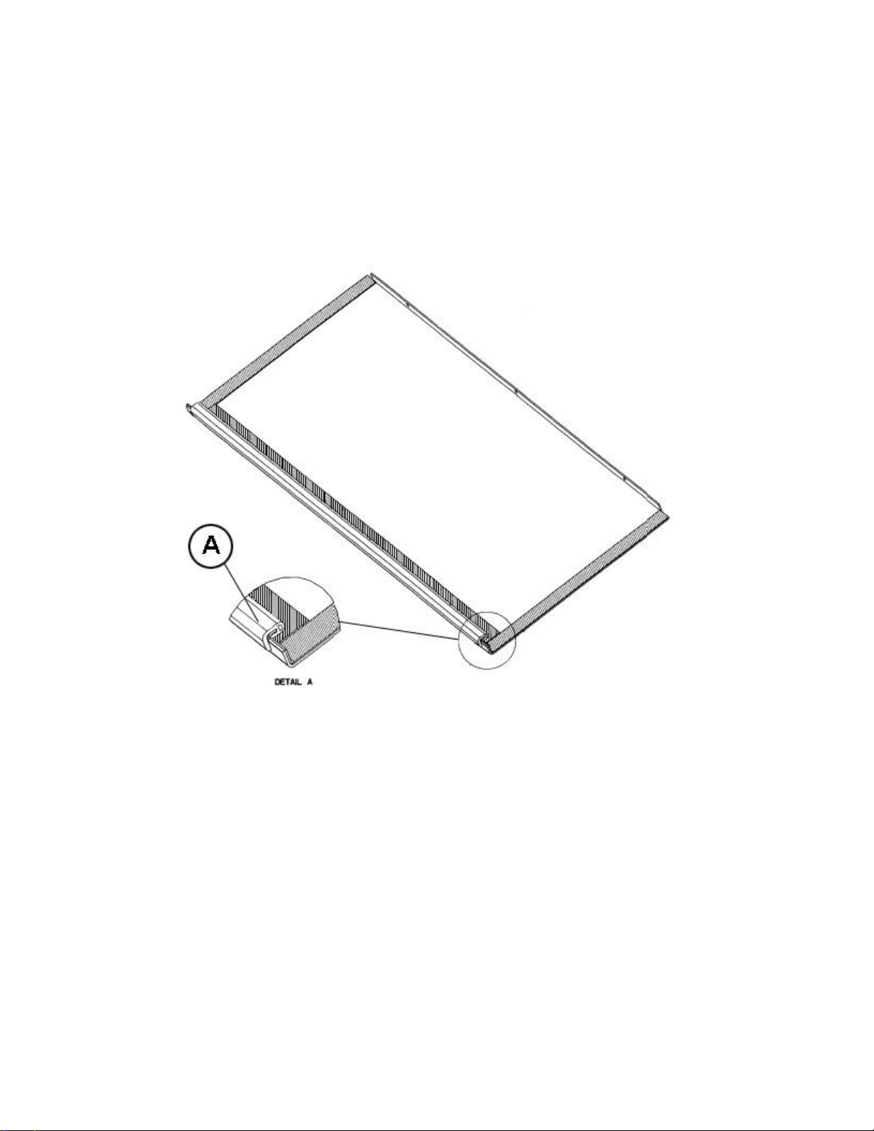
Base Pan Gasket
Page 14 of 15
29-January-2016
92-42800-RGTC
Page 15

NOTES
Stk It is recommended that stock be maintained for this part.
N/A Not Applicable
1 Order Gas Valve for Natural Gas along with LP Conversion Kit.
2 Jacket is not available as a replacement component.
DISCLAIMER: This document is intended to provide general replacement parts information to aid qualified
service personnel in the repair of these models. The complete Model and Serial Number of the unit under repair
should be specified when selecting and ordering replacement parts. Specifications and illustrations are subject
to change without notice. Document 92-42800-RGTC supersedes all previous parts lists for these models. See
http://www.rheempartslists.net/92-42800-RGTC for the latest revision of this document. The manufacturer
assumes no obligation for errors or omissions. Service personnel must verify the proper and safe operation of
equipment after the replacement of any original components.
P.O. Box 17010
Fort Smith, AR 72917-7010
 Loading...