

Rheem RGRJ series, RGRA series, RGTJ series, RGTA series Installation Instructions Manual
!
If the information in these instructions is not followed exactly, a
fire or explosion may result, causing property damage, personal
injury or death.
INSTALLATION INSTRUCTIONS
FOR UPFLOW & DOWNFLOW/HORIZONTAL HIGH
EFFICIENCY CONDENSING GAS FURNA CES
RGRA/RGRJ AND RGTA/RGTJ SERIES
92-23531-16-09
SUPERSEDES 92-23531-16-08
THESE INSTRUCTIONS ARE
INTENDED AS AN AID TO
QUALIFIED SERVICE
PERSONNEL FOR PROPER
INSTALLATION, ADJUSTMENT
AND OPERATION OF THIS
UNIT. READ THESE
INSTRUCTIONS THOROUGHLY
BEFORE ATTEMPTING
INSTALLATION OR
OPERATION. FAILURE TO
FOLLOW THESE
INSTRUCTIONS MAY RESULT
IN IMPROPER INSTALLATION,
ADJUSTMENT, SERVICE OR
MAINTENANCE, POSSIBLY
RESULTING IN FIRE,
ELECTRICAL SHOCK, CARBON
MONOXIDE POISONING,
EXPLOSION, PROPERTY
DAMAGE, PERSONAL INJURY
OR DEATH.
Do Not Destroy this Manual.
Please read carefully and keep
in a safe place for future
reference by a serviceman.
WARNING
Recognize this symbol as an indication of Important Safety Information!
!
— Do not store or use gasoline or other
flammable vapors and liquids, or other
combustible materials in the vicinity of this
or any other appliance.
— WHAT TO DO IF YOU SMELL GAS
• Do not try to light any appliance.
• Do not touch any electrical switch; do not
use any phone in your building.
• Immediately call your gas supplier from a
neighbor’s phone. Follow the gas
supplier’s instructions.
• If you cannot reach your gas supplier,
call the fire department.
• Do not return to your home until
authorized by the gas supplier or fire
department.
— DO NOT RELY ON SMELL ALONE TO
DETECT LEAKS. DUE TO VARIOUS
FACTORS, YOU MAY NOT BE ABLE TO
SMELL FUEL GASES.
• U.L. recognized fuel gas and CO
detectors are recommended in all
applications, and their installation should
be in accordance with the manufacturer’s
recommendations and/or local laws,
rules, regulations, or customs
— Improper installation, adjustment, alteration,
service or maintenance can cause injury,
property damage or death. Refer to this
manual. Installation and service must be
performed by a qualified installer, service
agency or the gas supplier.
WARNING
!
PROPOSITION 65: THIS FURNACE CONTAINS FIBERGLASS
INSULATION. RESPIRABLE PARTICLES OF FIBERGLASS ARE
KNOWN TO THE STATE OF CALIFORNIA TO CAUSE CANCER.
EXHAUST GAS FROM THIS FURNACE CONTAINS CHEMICALS,
INCLUDING CARBON MONOXIDE, KNOWN TO THE STATE OF
CALIFORNIA TO CAUSE BIRTH DEFECTS OR OTHER
REPRODUCTIVE HARM.
WARNING
!
FOR YOUR SAFETY
!

INSTALLATION CHECK LIST
REFER TO INSTALLATION INSTRUCTIONS
GAS SUPPLY
Adequate pipe size
Correct supply pressure (during furnace operation)
Manifold pressure
No gas leaks
ELECTRICAL
115 V.A.C. supply (Single Circuit)
Polarity observed
Furnace properly grounded
Adequate wire size
FURNACE INSTALLATION
Adequate clearance to combustibles
Adequate clearance for service (at front)
DUCT STATIC PRESSURE
in. w.c. on heating speed
in. w.c. on cooling speed
Air temperature rise
CONDENSATE LINE
Trap filled with water
Vented
Sloped toward drain
Condensate drain line hoses connected
and clamped
Freeze protection (if necessary)
VENTING – DIRECT VENT
in. diameter – intake pipe
in. diameter – exhaust pipe
ft. of pipe – intake air
no. of elbows – intake air
ft. of pipe – exhaust pipe
no. of elbows – exhaust pipe
TERMINATIONS – DIRECT VENT
VERTICAL
Intake – 12" min. above roof/snow level
Correct relationship – exhaust to intake
VERTICAL – CONCENTRIC (RXGY-E02)
Intake – 12" min. above roof/snow level
HORIZONTAL – STANDARD (RXGY-D02, -D03)
Correct relationship – exhaust to intake
12" min. above grade/snow level
HORIZONTAL – ALTERNATE (RXGY-D02, -D03 OR -D04)
Correct relationship – exhaust to intake
Above anticipated snow level
HORIZONTAL – CONCENTRIC (RXGY-C01)
12" min. above grade/snow level
Intake “Y” rotated above center
Exhaust sloped toward furnace
VENTING – NON-DIRECT VENT
in. diameter – exhaust pipe
ft. of pipe – exhaust
no. of elbows
TERMINATION – NON-DIRECT VENT
VERTICAL
12" min. above roof/snow level
HORIZONTAL – STANDARD
12" min. above grade/snow level
HORIZONTAL – ALTERNATE
Above anticipated snow level
2

3
IMPORTANT: TO INSURE PROPER INSTALLATION AND OPERATION OF
THIS PRODUCT, COMPLETELY READ ALL INSTRUCTIONS PRIOR TO
ATTEMPTING TO ASSEMBLE, INSTALL, OPERATE, MAINTAIN OR REPAIR
THIS PRODUCT. UPON UNPACKING OF THE FURNACE, INSPECT ALL
PARTS FOR DAMAGE PRIOR TO INSTALLATION AND START-UP.
CONTENTS
Safety Precautions...................................................................................................1
Installation Check List ..............................................................................................2
Location Requirements and Considerations............................................................5
Venting and Combustion Air Piping .......................................................................12
Combustion and Ventilation Air..............................................................................14
Vent Pipe Installation..............................................................................................17
Condensate Drain/Neutralizer................................................................................27
Converting Downflow to Horizontal........................................................................29
Gas Supply and Piping...........................................................................................31
Electrical Wiring......................................................................................................35
Accessories............................................................................................................37
Start-Up Procedures...............................................................................................44
Air Flow...................................................................................................................46
Maintenance...........................................................................................................50
Troubleshooting......................................................................................................53
Wiring Diagrams.....................................................................................................59
➤ Installation Instructions are updated on a regular basis. This is done as
product changes occur or if new information becomes available. In this
publication, an arrow (➤) denotes changes from the previous edition or additional
new material.
GENERAL INFORMATION
The RGRA/RGRJ and RGTA/RGTJ
series furnaces are design-certified
by AGA/CGA for use with natural and
propane gases as follows:
1. As non-direct vent central forced
air furnaces taking combustion
air from the installation area or
using air ducted from the outside.
2. As direct vent central forced air
furnaces with all combustion air
supplied directly to the furnace
burners through a special air
intake system outlined in these
instructions.
4
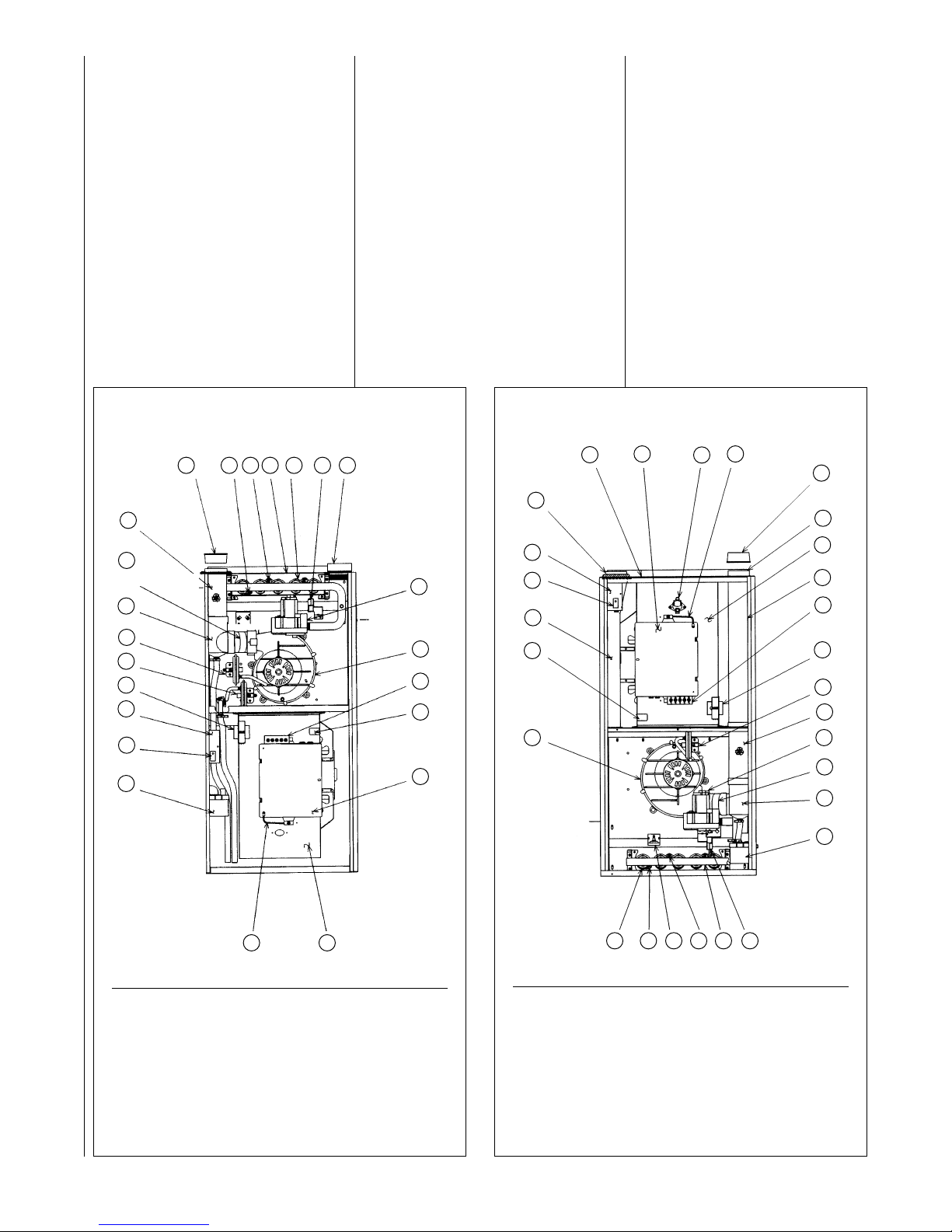
FIGURE 1
UPFLOW FURNACE
FIGURE 2
DOWNFLOW/HORIZONTAL FURNACE
Install this furnace in accordance with
the American National Standard
Z223.1 – latest edition entitled
“National Fuel Gas Code” (NFPA54)
and requirements or codes of the
local utilities or other authorities
having jurisdiction. This is available
from the following:
National Fire Protection
Association, Inc.
Batterymarch Park
Quincy, MA 02269
American Gas Association
1515 Wilson Blvd.
Arlington, VA 22209
Install units in Canada in accordance
with CAN/CGA-B149, local
installation codes and authorities
having jurisdiction. CAN/CGA-B149 is
available from:
Canadian Gas Association
55 Scarsdale Road
Don Mills, Ontario, Canada M3B, 2R3
2425262728
ITEM ITEM
NO. PART NAME NO. PART NAME
1 INDUCED DRAFT BLOWER 15 LOW VOLTAGE TERMINAL
2 CAPACITOR 16 TRANSFORMER
3 INLET AIR CHASE 17 PRESSURE SWITCH
4 DOOR SWITCH 18 OUTLET AIR PIPE
5 JUNCTION BOX 19 GAS VALVE
6 INLET PIPE CONNECTOR 20 CONNECTOR
7 TOP PLATE 21 EXHAUST TRANSITION
8 ELECTRICAL BOX 22 CONDENSATE TRAP
9 AUXILLIARY LIMIT 23 IGNITER
10 CONTROL BOX COVER GROUND 24 MANIFOLD
11 VENT CAP PLUG 25 OVERTEMPERATURE SWITCH
12 EXHAUST CONNECTION 26 ROLLOUT SWITCH
13 BLOWER 27 SENSOR
14 EXHAUST PIPE EXTENSION 28 BURNER
ITEM ITEM
NO. PART NAME NO. PART NAME
1 CONDENSATE TRAP 13 TOP PLATE
2 DOOR SWITCH 14 BURNER
3 JUNCTION BOX 15 IGNITER
4 TRANSFORMER 16 COMBUSTION AIR INLET
5 BLOCKED DRAIN PRESSURE SWITCH 17 GAS VALVE
6 MAIN PRESSURE SWITCH 18 INDUCED DRAFT BLOWER
7 EXHAUST TRANSITION 19 LOW VOLTAGE TERMINAL
8 CONNECTOR 20 CAPACITOR
9 OUTLET AIR PIPE 21 ELECTRICAL BOX
10 VENT CAP PLUG 22 BLOWER
11 SENSOR 23 CONTROL BOX
12 OVERTEMPERATURE SWITCH
COVER GROUND
1
2
3
4
5
6
7
8
9
10
11
12
13
14
15
16
17
18
19
20
21
22
23
1
2
3
4
5
6
7
8
9
10 11 12 13 14 15 16
17
18
19
20
21
2223
GAS INLET
OPTIONAL
COMBUSTION
AIR INLET
I409 I409
GAS
INLET
PVC
PVC
GENERAL INFORMATION
1.
IMPORTANT: If furnace
operation is required during
construction, and air ladened
with corrosive compounds such
as chlorine and fluorine are
present, provisions must be
taken to provide clean outdoor
combustion and ventilation air to
the furnace. Compounds of
chlorine and fluorine, when
burned with combustion air, form
acids which will cause corrosion
of a heat exchanger. Some of
these compounds are found in
paneling, dry wall, tile adhesives,
paints, stains and varnishes,
solvents and masonry curing and
cleaning materials.
DO NOT INSTALL THIS FURNACE
IN A MOBILE HOME!! This furnace
is not approved for installation in a
mobile home. Doing so could cause
FIRE, PROPERTY DAMAGE,
PERSONAL INJURY OR DEATH.
WHEN THIS FURNACE IS
INSTALLED IN A RESIDENTIAL
GARAGE, IT MUST BE INSTALLED
SO THE BURNERS AND IGNITION
SOURCE ARE LOCATED NO LESS
THAN 18 INCHES ABOVE THE
FLOOR. THIS IS TO PREVENT
THE RISK OF IGNITING FLAMMABLE VAPORS WHICH MAY
BE PRESENT IN A GARAGE.
ALSO, THE FURNACE MUST BE
LOCATED OR PROTECTED TO
AVOID PHYSICAL DAMAGE BY
VEHICLES. FAILURE TO FOLLOW
THESE WARNINGS CAN CAUSE A
FIRE OR EXPLOSION, RESULTING
IN PROPERTY DAMAGE,
PERSONAL INJURY OR DEATH.
5
2.
IMPORTANT: If installing the
unit over a finished ceiling or
living area, be certain to install
an auxiliary condensate drain
pan under the entire unit. This
auxiliary drain pan should extend
under any evaporator coil
installed with the furnace.
3.
IMPORTANT: If using a cooling
evaporator coil with this
furnace:
a. be sure the air passes over
the heat exchanger before
passing over the cooling
coil. The cooled air passing
over the warm ambient air
inside the heat exchanger
tubes can cause
condensation inside the tubes
resulting in corrosion and
eventual failure.
b. install a parallel duct system
to divert all the air from the
furnace allowing it to pass
over the cooling coil only. Use
dampers or other means to
prevent chilled air from
passing over the heat
exchanger.
If these are manual dampers, they
must be equipped to prevent heating
or cooling operation unless the
damper is in the full heat or cool
position.
!
WARNING
!
WARNING
4.
IMPORTANT: Install the
furnace level. If it is not level,
condensate cannot drain
properly, possibly causing
furnace shut down.
NOTE: These furnaces are approved
for installation in attics, as well as
alcoves, utility rooms, closets and
crawlspaces. Provisions must be
made to prevent freezing of
condensate.
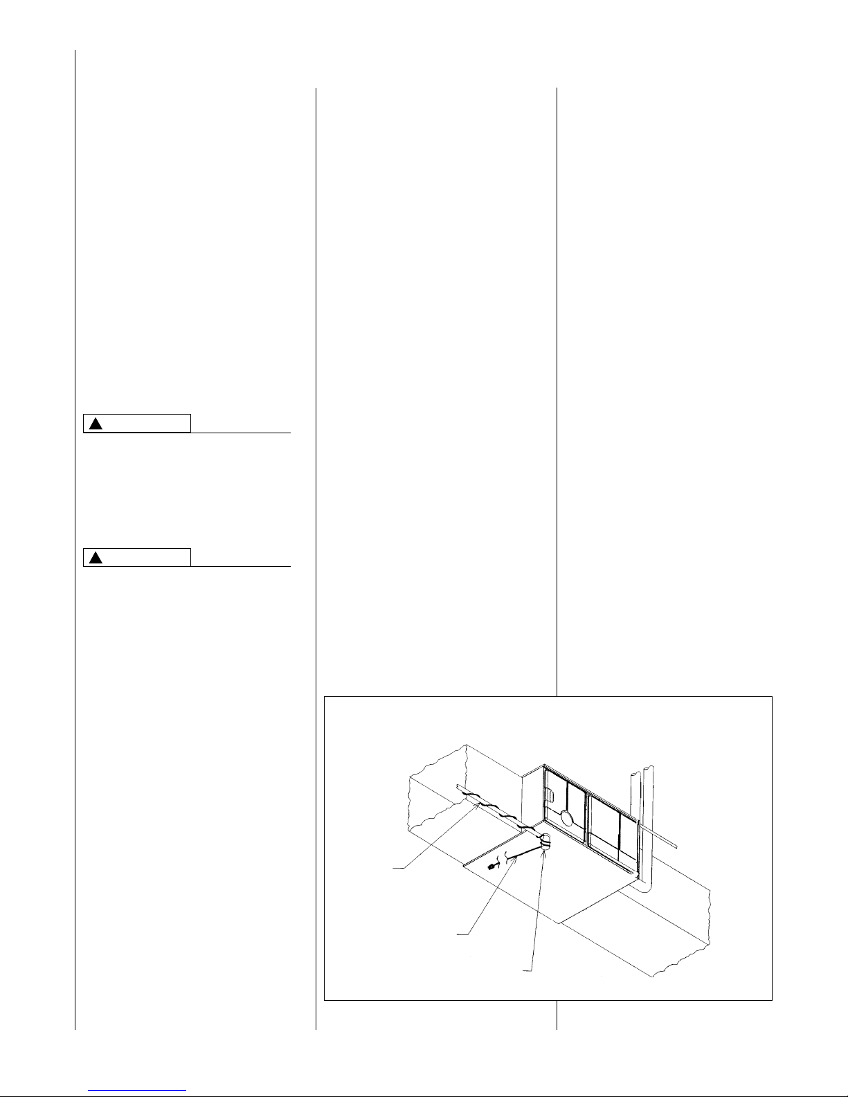
5.
IMPORTANT: If this furnace is
installed in a garage, attic
and/or any unconditioned
space, install a self-regulating
heat tape around the
condensate trap and along the
entire length of the condensate
drain in the unconditioned
space. See Figure 3.
When the condensing horizontal
gas furnace is installed in an
unconditioned space where the
temperature would be capable of
reaching close to or below 32°F
(0°C). A SELF-REGULATING
HEAT TAPE IS REQUIRED ON
THE CONDENSATE DRAIN,
ALONG WITH AN INSULATION
WRAP. The heat tape should
meet the following requirements:
LOCATION REQUIREMENTS AND CONSIDERATIONS
FIGURE 3
HORIZONTAL FURNACE W/HEAT TAPE ON CONDENSATE TRAP
DRAIN
PIPE
HEAT
TAPE
TRAP
I526
6
a. The heat tape must be UL
listed.
b. The heat tape must be
installed per the
manufacturer’s instructions for
the entire length of drain pipe
in the unconditioned space.
c. The heat tape should be rated
at 5 or 6 watts per foot at
120V.
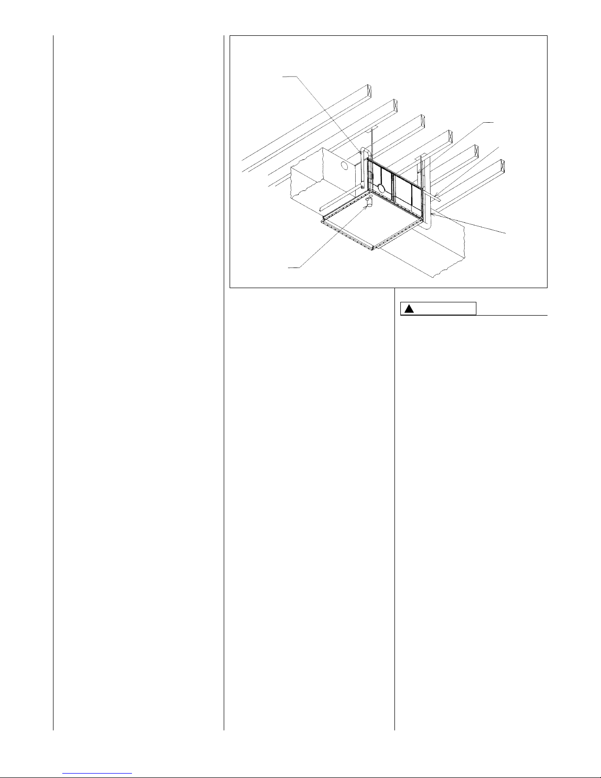
IMPORTANT: Support this unit
when installed. Since this
furnace is suitable for attic or
crawl space installation, it may
be installed on combustible wood
flooring or by using support
brackets. See Figure 4.
6.
IMPORTANT: If installing in a
utility room, be sure the door
is wide enough to:
a. allow the largest part of the
furnace to pass; or
b. allow any other appliance
(such as a water heater)
to pass.
7. IMPORTANT: This furnace is
not approved or recommended
for installation on its back,
with access doors facing
upwards.
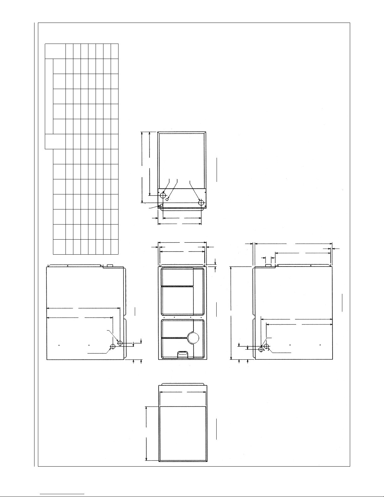
CLEARANCE ACCESSIBILITY
The design of forced air furnaces with
input ratings as listed in the tables
under Figures 6, 7 and 8 are certified
by the AGA Laboratories and CGA
Laboratories for the clearances to
combustible materials shown in
inches.
FIGURE 4
HORIZONTAL FURNACE INSTALLED W/SUPPORT BRACKETS
GAS
PIPE
TRAP
EXHAUST
FAN
ELECTRICAL
CONDUIT
INTAKE
VENT
See name/rating plate and clearance
label for specific model number and
clearance information.
Service clearance of at least 24
inches is recommended in front of
all furnaces.
FOR PURPOSES OF SERVICING
THIS APPLIANCE, ACCESSIBILITY
CLEARANCES, WHERE GREATER,
MUST TAKE PRECEDENCE OVER
FIRE PROTECTION CLEARANCES.
UPFLOW AND HORIZONTAL
FURNACES ARE DESIGNCERTIFIED FOR INSTALLATION
ON COMBUSTIBLE FLOORS.
NOTE, HOWEVER, THAT FURNACES MUST NOT BE INSTALLED
DIRECTLY ON CARPETING, TILE
OR OTHER COMBUSTIBLE
MATERIAL OTHER THAN WOOD
FLOORING. INSTALLATION ON A
COMBUSTIBLE MATERIAL CAN
RESULT IN FIRE, CAUSING
PROPERTY DAMAGE, PERSONAL
INJURY OR DEATH.
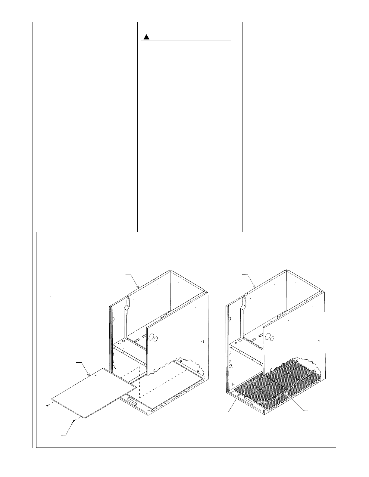
Upflow furnaces are shipped with a
bottom closure panel installed. When
bottom return air is used, remove the
panel by removing the two screws
attaching the panel to the front base
angle. See Figure 5.
!
WARNING
I522
7
SITE SELECTION
1. Select a site in the building near
the center of the proposed, or
existing, duct system.
2. Give consideration to the vent
system piping when selecting the
furnace location. Be sure the
venting system can get from the
furnace to the termination with
minimal length and elbows.
3. Locate the furnace near the
existing gas piping. Or, if running
a new gas line, locate the
furnace to minimize the length
and elbows in the gas piping.
4. Locate the furnace to maintain
proper clearance to combustibles
as shown in the following tables.
!
WARNING
COMBUSTIBLE MATERIAL MUST
NOT BE PLACED ON OR AGAINST
THE FURNACE JACKET. THE
AREA AROUND THE FURNACE
MUST BE KEPT CLEAR AND FREE
OF ALL COMBUSTIBLE
MATERIALS INCLUDING GASOLINE AND OTHER FLAMMABLE
VAPORS AND LIQUIDS.
PLACEMENT OF COMBUSTIBLE
MATERIALS ON, AGAINST OR
AROUND THE FURNACE JACKET
CAN CAUSE AN EXPLOSION OR
FIRE RESULTING IN PROPERTY
DAMAGE, PERSONAL INJURY OR
DEATH. THE HOMEOWNER
SHOULD BE CAUTIONED THAT
THE FURNACE AREA MUST NOT
BE USED AS A BROOM CLOSET
OR FOR ANY OTHER STORAGE
PURPOSES.
FIGURE 5
BOTTOM PANEL REMOVAL
JACKET ASSEMBLY
SOLID BOTTOM
NOTE:
BACK FLANGE OF SOLID BOTTOM FITS
UNDERNEATH JACKET. SIDES AND FRONT
FLANGES FIT OVER FLANGES ON JACKET.
SCREW
(2) REQ’D.
JACKET ASSEMBLY
FILTER
FILTER
ROD
SOLID BOTTOM REMOVAL
FILTER & ROD LOCATION
ADS 5422-01
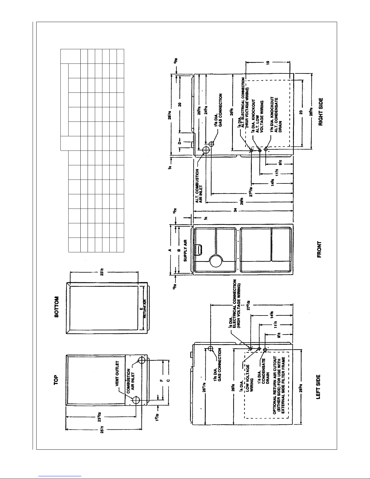
FIGURE 6
CLEARANCE TO COMBUSTIBLES, UPFLOW UNITS
8
UPFLOW MODELS MINIMUM CLEARANCE (IN.)
LEFT RIGHT SHIP
MODEL A B C D E F
SIDE SIDE
BACK TOP FRONT VENT
WGTS
04 17
1
/2 16
11
/32 15
5
/8 21513
25
/32 00012*0 111
06 17
1
/2 16
11
/32 15
5
/8 21513
25
/32 00012*0 117
07 17
1
/2 16
11
/32 15
5
/8 21513
25
/32 00012*0 123
09 21 19
27
/32 19
1
/8 218
1
/217
9
/32 00012*0 148
10 21 19
27
/32 19
1
/8 218
1
/217
9
/32 00012*0 152
12 24
1
/2 23
11
/32 22
5
/8 22220
25
/32 00012*0 160
I392
➤*A service clearance of at least 24 inches is recommended in front of all furnaces.
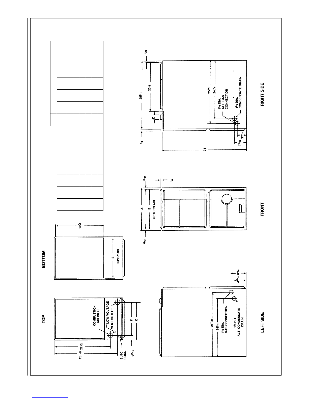
FIGURE 7
CLEARANCE TO COMBUSTIBLES, DOWNFLOW UNITS
9
DOWNFLOW MODELS MINIMUM CLEARANCE (IN.)
LEFT RIGHT SHIP
MODEL A B C D E F
SIDE SIDE
BACK TOP FRONT VENT
WGTS
04 17
1
/2
16
11
/32
15
5
/8
216
5
/8
13
7
/8
00012*0 111
06 17
1
/2 16
11
/32 15
5
/8 216
5
/813
7
/8 00012*0 117
07 17
1
/
2 16
11
/
32 15
5
/
8 216
5
/
813
7
/
8 00012*0 123
09 21 19
27
/
32 19
3
/
16 220
1
/
817
3
/
8 00012*0 148
10 21 19
27
/
32 19
3
/
16 220
1
/
817
3
/
8 00012*0 152
12 24
1
/
2 23
11
/
32 22
5
/
8 223
5
/
820
7
/
8 00012*0 160
I393
➤*A service clearance of at least 24 inches is recommended in front of all furnaces.
➤ FIGURE 8
CLEARANCE TO COMBUSTIBLES, HORIZONTAL UNITS
DOWNFLOW MODELS MINIMUM CLEARANCE (IN.)
LEFT RIGHT SHIP
MODEL A B C D E F
SIDE SIDE
BACK TOP FRONT VENT
WGTS
04 17
1
/2 16
11
/32 15
5
/8 216
5
/813
7
/8 00012*0 111
06 17
1
/2 16
11
/32 15
5
/8 216
5
/813
7
/8 00012*0 117
07 17
1
/2 16
11
/32 15
5
/8 216
5
/813
7
/8 00012*0 123
07 21 19
27
/32 19
3
/16 220
1
/817
3
/8 00012*0 123
09 21 19
27
/32 19
3
/16 220
1
/817
3
/8 00012*0 148
10 21 19
27
/32 19
3
/16 220
1
/817
3
/8 00012*0 152
12 24
1
/2 23
11
/32 22
5
/8 223
5
/820
7
/8 00012*0 160
10
I520
*A service clearance of at least 24 inches is recommended in front of all furnaces.
1
5
⁄8 DIA.
ALT. CONDENSATE
DRAIN
1
5
⁄8 DIA.
GAS
CONNECTION
TOP
LEFT SIDE FRONT
BOTTOM
RIGHT SIDE
4
13
⁄16
6
1
⁄64
24
1
⁄16
19
7
⁄8
23
31
⁄32
1
13
⁄16
34
4
13
⁄16
25
3
⁄32
D
28
1
⁄16
20
1
⁄18
19
⁄32
24
1
⁄16
3
⁄4
3
11
⁄16
1
5
⁄8 DIA.
ALT. GAS
CONNECTION
1
5
⁄8 DIA.
CONDENSATE
DRAIN
COMBUSTION
AIR INLET
LOW VOLTAGE
RETURN
AIR
VENT OUTLET
22
3
⁄32
ELECT.
CONN.
19
⁄32
19
⁄32
3
⁄4
E
B
A
C
F
SUPPL
Y
26
11
⁄16
11
DUCTING
Proper air flow is required for the
correct operation of this furnace.
Too little air flow can cause erratic
operation and can damage the heat
exchanger. The duct system must
carry the correct amount of air for
heating and cooling if summer air
conditioning is used.
Size the ducts according to
acceptable industry standards and
methods. The total static pressure
drop of the air distribution system
should not exceed 0.5" w.c.
NEVER ALLOW THE PRODUCTS
OF COMBUSTION FROM THE
FLUE TO ENTER THE RETURN AIR
DUCTWORK OR THE
CIRCULATED AIR SUPPLY. ALL
RETURN DUCTWORK MUST BE
ADEQUATELY SEALED AND
SECURED TO THE FURNACE
WITH SHEET METAL SCREWS;
AND JOINTS, TAPED. ALL OTHER
DUCT JOINTS MUST BE SECURED
WITH APPROVED CONNECTIONS
AND SEALED AIRTIGHT. WHEN AN
UPFLOW FURNACE IS MOUNTED
ON A PLATFORM WITH RETURN
THROUGH THE BOTTOM, IT MUST
BE SEALED AIRTIGHT BETWEEN
THE FURNACE AND THE RETURN
AIR PLENUM. THE FLOOR OR
PLATFORM MUST PROVIDE
SOUND PHYSICAL SUPPORT OF
THE FURNACE WITHOUT
SAGGING, CRACKS, OR GAPS,
AROUND THE BASE, PROVIDING A
SEAL BETWEEN THE SUPPORT
AND THE BASE.
FAILURE TO PREVENT
PRODUCTS OF COMBUSTION
FROM BEING CIRCULATED INTO
THE LIVING SPACE CAN CREATE
POTENTIALLY HAZARDOUS
CONDITIONS, INCLUDING
CARBON MONOXIDE POISONING
THAT COULD RESULT IN
PERSONAL INJURY OR DEATH.
DO NOT, UNDER ANY
CIRCUMSTANCES, CONNECT
RETURN OR SUPPLY DUCTWORK
TO OR FROM ANY OTHER HEAT
PRODUCING DEVICE SUCH AS A
FIREPLACE INSERT, STOVE, ETC.
DOING SO MAY RESULT IN FIRE,
CARBON MONOXIDE POISONING,
EXPLOSION, PERSONAL INJURY
OR PROPERTY DAMAGE.
IMPORTANT: Some high efficiency
filters have a greater than normal
resistance to air flow. This can
adversely affect furnace operation.
BE SURE TO CHECK AIR FLOW if
using any filter other than the factoryprovided filter.
UPFLOW UNITS
1. Position the unit to minimize long
runs of duct or runs of duct with
many turns and elbows.
2. Open the return air compartment.
a. If using side or back return air,
do not remove the bottom
base.
b. Cut an opening in the side or
back. The opening should
be cut the full width of the
knockouts on the unit.
c. Remove the bottom base if
using bottom return air.
NOTE: Where the maximum air flow
is 1800 CFM or more, both sides or
the bottom must be used for return
air.
3. Connect the return duct or return
air cabinet to the unit. Make the
connection air tight to prevent
entraining combustion gases
from an adjacent fuel-burning
appliance.
4. Be sure to have adequate
space for the unit filter.
NOTE: DO NOT take return air
from bathrooms, kitchens,
furnace rooms, garages, utility or
laundry rooms, or cold areas.
5. If summer air conditioning is
desired, position the indoor coil
on the top of the unit. Insure that
no air can bypass this coil.
6. Connect the supply air plenum to
the furnace plenum opening.
IMPORTANT: If a flexible duct
connector must be used, it
MUST
be rated for a minimum
temperature of 250
°F.
continuous.
DOWNFLOW UNITS
1. Position the unit to minimize long
runs of duct or runs of duct with
many turns and elbows.
2. If summer air conditioning is
desired, position the indoor coil
on the bottom of the unit. Insure
that no air can bypass this coil.
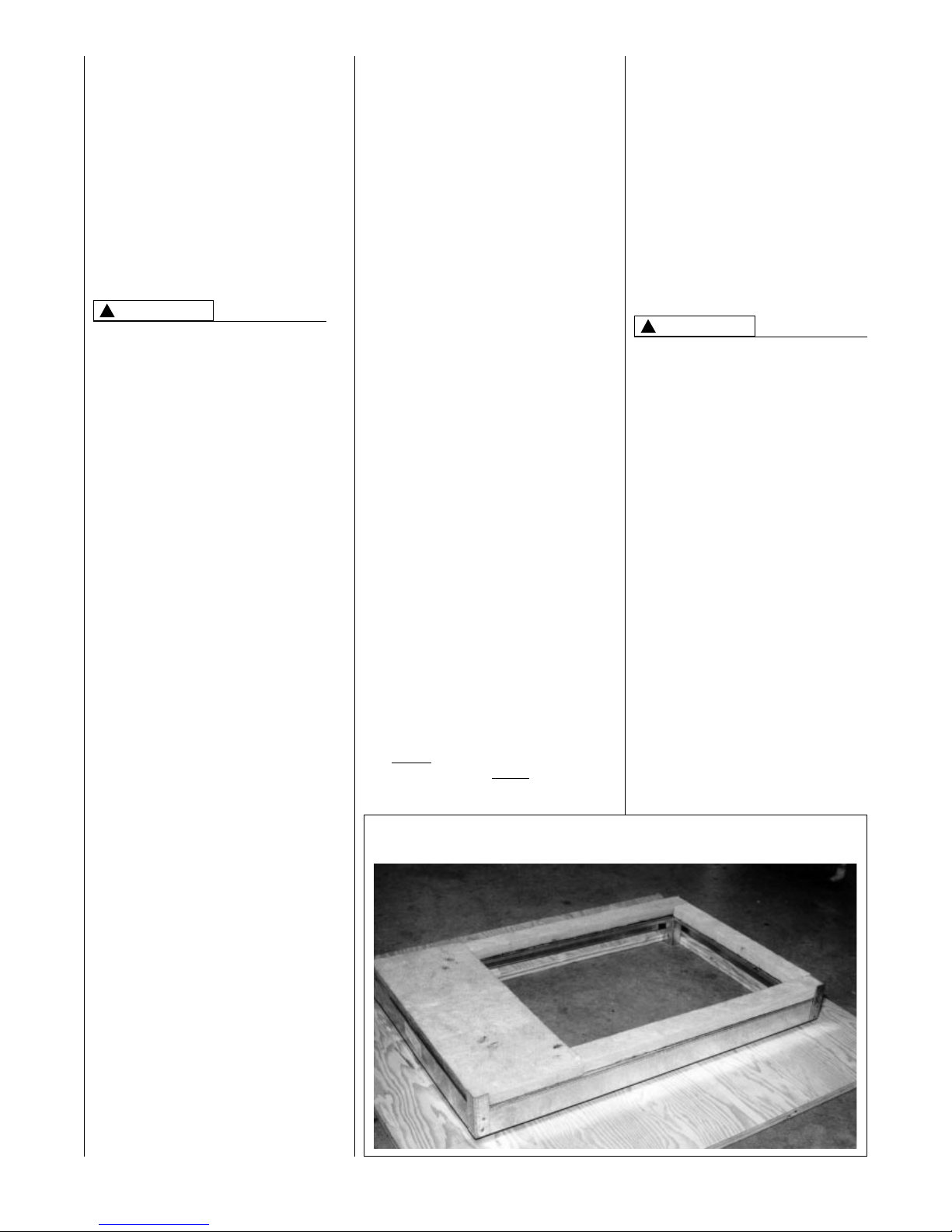
3. If installing on a combustible floor
and not using an air conditioning plenum, install the special
non-combustible floor base. See
Figure 9.
THE DOWNFLOW FURNACE
DESIGN IS CERTIFIED FOR
INSTALLATION ON A NONCOMBUSTIBLE FLOOR. USE THE
SPECIAL BASE SPECIFIED ON
THE FURNACE CLEARANCE
LABEL. FAILURE TO INSTALL THE
SPECIAL BASE MAY RESULT IN
FIRE, PROPERTY DAMAGE,
PERSONAL INJURY OR DEATH.
THIS SPECIAL BASE IS SHIPPED
FROM THE FACTORY AS AN
ACCESSORY.
4. Connect the furnace to the
supply air plenum.
5. Connect the return air ducting to
the return air opening at the top
of the unit. Make the connection
air tight to prevent entraining
combustion gases from an
adjacent fuel-burning appliance.
6. Be sure to have adequate
space for the unit filter.
NOTE: DO NOT take return air
from bathrooms, kitchens,
furnace rooms, garages, utility or
laundry rooms, or cold areas.
!
WARNING
!
WARNING
FIGURE 9
COMBUSTIBLE FLOOR BASE
12
GENERAL INFORMATION
READ AND FOLLOW ALL INSTRUCTIONS IN THIS SECTION.
FAILURE TO PROPERLY VENT
THIS FURNACE CAN CAUSE
CARBON MONOXIDE POISONING
OR AN EXPLOSION OR FIRE,
RESULTING IN PROPERTY
DAMAGE, PERSONAL INJURY
OR DEATH.
This furnace removes both sensible
and latent heat from the combustion
flue gases. Removal of latent heat
results in condensation of flue gas
water vapor. This condensed water
vapor drains from the secondary heat
exchanger and out of the unit into a
drain trap.
When installed as a non-direct vent
furnace, only exhaust piping is
required and inside combustion air
may be used. Refer to section on
“
COMBUSTION & VENTILATION AIR
FOR FURNACE INSTALLATIONS.”
Direct vent installations require a
dedicated combustion air and venting
system. All air for combustion is taken
from the outside atmosphere and all
combustion products are discharged
to the outdoors.
The combustion air and vent pipe
fittings must conform to American
National Standards Institute (ANSI)
and American Society for Testing
Materials (ASTM) standards
D1785 (Schedule 40 PVC), D2665
(PVC-DWV), D2241 (SDR-21 and
SDR26-26 PVC), D2661 (ABS-DWV)
or F628 (Schedule 40 ABS-DWV).
In Canada all combustion air and vent
pipe must be CSA- or ULC-certified
Schedule 40 PVC, PVC-DWV or
ABS-DWV.
IMPORTANT: The plastic combustion
air and venting components are of
Schedule 40 PVC. If using ABS
piping, ensure that the solvent
cement is compatible for joining
PVC to ABS components or use a
mechanical connection that can
withstand the vent temperatures and
are corrosion resistant.
NOTE: Schedule 40 ABS-DWV pipe
and fittings may be used as an
alternate to PVC pipe for the
combustion air inlet and vent pipes.
NOTE: Cellular core PVC is also
approved for use. It must be schedule
40PVC-DWV cellular pipe for nonpressure applications and
manufactured under ASTM F-891.
OVERTEMPERATURE
SAFETY SWITCHES
Furnaces are equipped with safety
switches in the control compartment
to protect against overtemperature
conditions caused by inadequate
combustion air supply. The switches
for the upflow and downflow models
are located in the burner
compartment. If a switch is tripped it
must be manually reset.
DO NOT JUMPER THESE
DEVICES! IF ONE OF THESE
SWITCHES SHOULD TRIP, A
QUALIFIED INSTALLER, SERVICE
AGENCY OR THE GAS SUPPLIER
MUST BE CALLED TO CHECK
AND/OR CORRECT FOR
ADEQUATE COMBUSTION AIR
SUPPLY. DO NOT RESET THE
SWITCHES WITHOUT TAKING
CORRECTIVE ACTION TO ASSURE
THAT AN ADEQUATE SUPPLY OF
COMBUSTION AIR IS MAINTAINED
UNDER ALL CONDITIONS OF
OPERATION. FAILURE TO DO SO
CAN RESULT IN CARBON
MONOXIDE POISONING OR
DEATH. IF THIS UNIT IS MOUNTED
IN A CLOSET, THE DOOR MUST
BE CLOSED WHEN MAKING THIS
CHECK.
REPLACE THESE SWITCHES
ONLY WITH THE IDENTICAL
REPLACEMENT PART.
EXISTING VENT SYSTEMS
When the installation of this furnace
replaces an existing furnace that is
removed from a vent system serving
other appliances, the vent system is
likely to be too large to properly vent
the remaining attached appliances.
The following steps should be
followed with each appliance
remaining connected to the original
common vent system. Place the
appliance to be tested in operation,
while the other appliances remaining
connected to the common vent
system are not in operation. Test the
operation of each appliance
individually by the following method.
1. Permanently seal any unused
openings in the common venting
system.
2. Visually inspect the venting
system for proper size and
horizontal pitch and determine
that there is no blockage,
restriction, leakage, corrosion or
other deficiencies which could
cause an unsafe condition.
3. If practical, close all building
doors, windows and all doors
between the space where the
appliances remaining connected
to the common venting system
are located.
Turn on clothes dryers and any
appliance not connected to the
common venting system. Turn on
any exhaust fans, such as range
hoods and bathroom exhausts,
so they will operate at maximum
speed. Do not operate a summer
exhaust fan. Close fireplace
dampers.
VENTING AND COMBUSTION AIR PIPING
!
WARNING
!
WARNING
HORIZONTAL UNIT
IMPORTANT: THIS FURNACE MAY
ONLY BE INSTALLED SO AS
WHEN FACING THE FRONT OF
THE FURNACE, SUPPLY AIR IS
DISCHARGED ON THE LEFT HAND
SIDE.
1. Position the unit to minimize long
runs or runs with many turns and
elbows.
2. If summer air conditioning is
desired, position the indoor coil
on the left end of the unit. Insure
that no air can bypass this coil.
3. Connect the furnace to the
supply air plenum.
4. Connect the return air ducting to
the return air opening at the right
end of the unit. Make the
connection air tight to prevent
entraining combustion gases
from an adjacent fuel-burning
appliance.
5. Be sure to have adequate
space for the unit filter.
NOTE: DO NOT take return air
from bathrooms, kitchens,
furnace rooms, garages, utility or
laundry rooms, or cold areas.

CEMENTING JOINTS
Properly seal all joints in the PVC
vent using the following materials and
procedures.
PVC CLEANER-PRIMER AND
PVC MEDIUM-BODY SOLVENT
CEMENT
IMPORTANT:
After cutting pipe,
remove all ragged edges and burrs.
This is important to prevent reduction
in pressure drop throughout the
system.
1. Cut pipe end square. Chamfer
edge of pipe. Clean fitting socket
and pipe joint area of all dirt,
grease and moisture.
2. After checking pipe and socket
for proper fit, wipe socket and
pipe with cleaner-primer. Apply
a liberal coat of primer to inside
surface of socket and outside of
pipe. Read instructions included
with the primer for proper
application.
3. Apply a thin coat of cement
evenly in the socket. Quickly
apply a heavy coat of cement to
the pipe end and insert pipe into
fitting with a slight twisting
movement until it bottoms out.
NOTE: Cement must be fluid; if
not, recoat.
4. Hold the pipe in the fitting for 30
seconds to prevent the tapered
socket from pushing the pipe out
of the fitting.
5. Wipe all excess cement from the
joint with a rag. Allow 15 minutes
before handling. Cure time varies
according to fit, temperature and
humidity.
NOTE: Stir the solvent cement
frequently while using. Use a natural
bristle brush or the dauber supplied
with the can. The proper brush size is
one inch.
IMPORTANT: For Proper Installation
DO NOT use solvent cement that
has become curdled, lumpy or
thickened.
DO NOT thin. Observe shelf
precautions printed on containers.
For application below 32°F, use only
low-temperature-type solvent
cement.
13
4. Follow the lighting instructions.
Place the appliance being
inspected into operation. Adjust
the thermostat so the appliance
will operate continuously.
5. Test for spillage at the draft hood
relief opening after 5 minutes of
main burner operation. Use the
flame of a match or candle, or
smoke from a cigarette, cigar
or pipe.
6. After it has been determined that
each appliance that remains
connected to the common
venting system properly vents
(when tested as outlined above),
return doors, windows, exhaust
fans, fireplace dampers and any
other gas-burning appliance to
their previous conditions of use.
7. If improper venting is observed
during any of the above tests, the
common venting system must be
resized. Refer to latest edition of
the National Fuel Gas Code
ANSI Z223.1, 1992 or the AGAGAMA venting tables for
Category I furnaces.
When the furnace is installed in the
same space with other gas
appliances such as a water heater, be
sure there is an adequate supply of
combustion and ventilation air for the
other appliances. Do not delete or
reduce the combustion air supply
required by the other gas appliances
in this space. See Z223.1, National
Fuel Gas Code (NFPA54) or
CAN/CGA-B149.1 and .2 for determining the combustion air requirements for gas appliances. An
unconfined space must have at least
50 cubic feet (volume) for each
1,000 BTUH of the total input of all
appliances in the space. If the open
space containing the appliances is in
a building with tight construction
(contemporary construction), outside
air may still be required for the
appliances to burn and vent properly.
Outside air openings should be sized
the same as for a confined space.
JOINING PIPE AND
FITTINGS
PVC SOLVENT CEMENTS AND
PRIMERS ARE HIGHLY FLAMMABLE. PROVIDE ADEQUATE
VENTILATION AND DO NOT
ASSEMBLE NEAR HEAT SOURCE
OR AN OPEN FLAME. DO NOT
SMOKE. AVOID SKIN OR EYE
CONTACT. OBSERVE ALL
CAUTIONS AND WARNINGS
PRINTED ON MATERIAL CONTAINERS. FAILURE TO FOLLOW
THESE GUIDELINES MAY RESULT
IN FIRE, EXPLOSION OR
ASPHYXIATION CAUSING
PERSONAL INJURY OR DEATH.
All pipe, fittings, solvent cement,
primers and procedures must
conform to American National
Standard Institute and American
Society for Testing and Materials
(ANSI/ASTM) standards in the U.S.
Pipe and Fittings - ASTM-D1785,
D2466, D2665, D2231, D2661 and
F628.
PVC Primer and Solvent Cement ASTM-D2564
ABS Pipe and Fittings - Use ABS
Primer and Solvent Cement D2235
Procedure for Cementing Joints ASTM-D2855
IMPORTANT: The plastic combustion
air and venting components are of
PVC. If using ABS piping, ensure that
the solvent cement is compatible for
joining PVC to ABS components or
use a mechanical connection that can
withstand the vent temperatures and
are corrosion resistant.
!
WARNING
14
NON-DIRECT
FURNACE INSTALLATIONS
THE FURNACE AND ANY OTHER
FUEL-BURNING APPLIANCE MUST
BE PROVIDED WITH ENOUGH
FRESH AIR FOR PROPER
COMBUSTION AND VENTILATION
OF THE FLUE GASES. MOST
HOMES WILL REQUIRE THAT
OUTSIDE AIR BE SUPPLIED INTO
THE FURNACE AREA. FAILURE
TO DO SO CAN CAUSE
PERSONAL INJURY OR DEATH
FROM CARBON MONOXIDE
POISONING.
Adequate facilities for providing air for
combustion and ventilation must be
provided in accordance with section
5.3, “Air for Combustion and
Ventilation” of the National Fuel Gas
Code, ANSI Z223.1-1992, CAN/CGA
B149.1 and 2, or applicable provisions for the local building codes,
and not obstructed so as to prevent
the flow of air to the furnace.
IMPORTANT: Air for combustion and
ventilation must not come from a
corrosive atmosphere. Any failure
due to corrosive elements in the
atmosphere is excluded from
warranty coverage.
The following types of installation
(but not limited to the following) will
require OUTDOOR AIR for combustion, due to chemical exposures:
• Commercial buildings
• Buildings with indoor pools
• Furnaces installed in laundry rooms
• Furnaces in hobby or craft rooms
• Furnaces installed near chemical
storage areas.
Exposure to the following substances
in the combustion air supply (but not
limited to the following) will also
require OUTDOOR AIR for
combustion:
• Permanent wave solutions
• Chlorinated waxes and cleaners
• Chlorine-based swimming pool
chemicals
• Water softening chemicals
• De-icing salts or chemicals
• Carbon tetrachloride
• Halogen type refrigerants
• Cleaning solvents (such as
perchloroethylene)
• Printing inks, paint removers,
varnishes, etc.
• Hydrochloric acid
• Cements and glues
• Antistatic fabric softeners for
clothes dryers
• Masonry curing and acid washing
materials
Combustion air must be free of acidforming chemicals such as sulphur,
fluorine and chlorine. These elements
are found in aerosol sprays,
detergents, bleaches, cleaning
solvents, air fresheners, paint and
varnish removers, refrigerants and
many other commercial and
household products. When burned in
a gas flame, vapors from these
products form acid compounds. The
acid compounds increase the dew
point temperature of the flue products
and are highly corrosive after they
condense.
ALL FURNACE INSTALLATIONS
MUST COMPLY WITH THE
NATIONAL FUEL GAS CODE AND
LOCAL CODES TO PROVIDE
ADEQUATE COMBUSTION AND
VENTILATION AIR FOR THE
FURNACE. FAILURE TO DO SO
CAN RESULT IN EXPLOSION,
FIRE, PROPERTY DAMAGE,
CARBON MONOXIDE POISONING,
PERSONAL INJURY OR DEATH.
Combustion air requirements are
determined by whether the furnace is
in an open (unconfined) area or in a
confined space such as a closet or
small room.
EXAMPLE 1:
FURNACE LOCATED IN AN
UNCONFINED SPACE
Using indoor air for combustion.
An unconfined space must have at
least 50 cubic feet for each 1,000
BTUH of the total input for all
appliances in the space. Here are a
few examples of the room sizes
required for different inputs. The sizes
are based on 8-foot ceilings.
BTUH Minimum Sq. Feet Typical Room Size
Input With 8' Ceiling With 8' Ceiling
45,000 281 14' x 20' OR 16' x 18'
60,000 375 15' x 25' OR 19' x 20'
75,000 469 15' x 31' OR 20' x 24'
90,000 563 20' x 28' OR 24' x 24'
105,000 657 20' x 33' OR 26' x 25'
120,000 750 25' x 30' OR 24' x 32'
If the open space containing the
furnace is in a building with tight
construction, outside air may still be
required for the furnace to operate
and vent properly. Outside air
openings should be sized the same
as for a confined space.
EXAMPLE 2:
FURNACE LOCATED IN A
CONFINED SPACE
A confined space (any space smaller
than shown above as “unconfined”)
must have openings into the space
which are located in accordance with
the requirements set forth in the
following subsections A and B. Size
the openings by how they are
connected to the heated area or to
the outside,
and by the input of all appliances in
the space.
If confined space is within a building
with tight construction, combustion air
must be taken from outdoors or area
freely communicating with the
outdoors.
A. USING INDOOR AIR FOR
COMBUSTION
IMPORTANT: Air should not be
taken from a heated space with
a fireplace, exhaust fan or other
device that may produce a
negative pressure.
If combustion air is taken from the
heated area, the openings must
each have at least 100 square
inches of free area. Each opening
must have at least one square inch
of free area for each 1,000 BTUH
of total input in the space. Here
are some examples of typical
openings required.
COMBUSTION AND VENTILATION AIR
!
WARNING
!
WARNING
15
BTUH Free Area
Input Each Opening
45,000 100 square inches
60,000 100 square inches
75,000 100 square inches
90,000 100 square inches
105,000 105 square inches
120,000 120 square inches
B. USING OUTDOOR AIR FOR
COMBUSTION
IMPORTANT: Do not take air
from an attic space that is
equipped with power ventilation.
The confined space must
communicate with the outdoors in
accordance with Methods 1 or 2.
The minimum dimension of air
openings shall not be less than 3
inches. Where ducts are used,
they shall be of the same crosssectional area as the free area of
the openings to which they
connect.
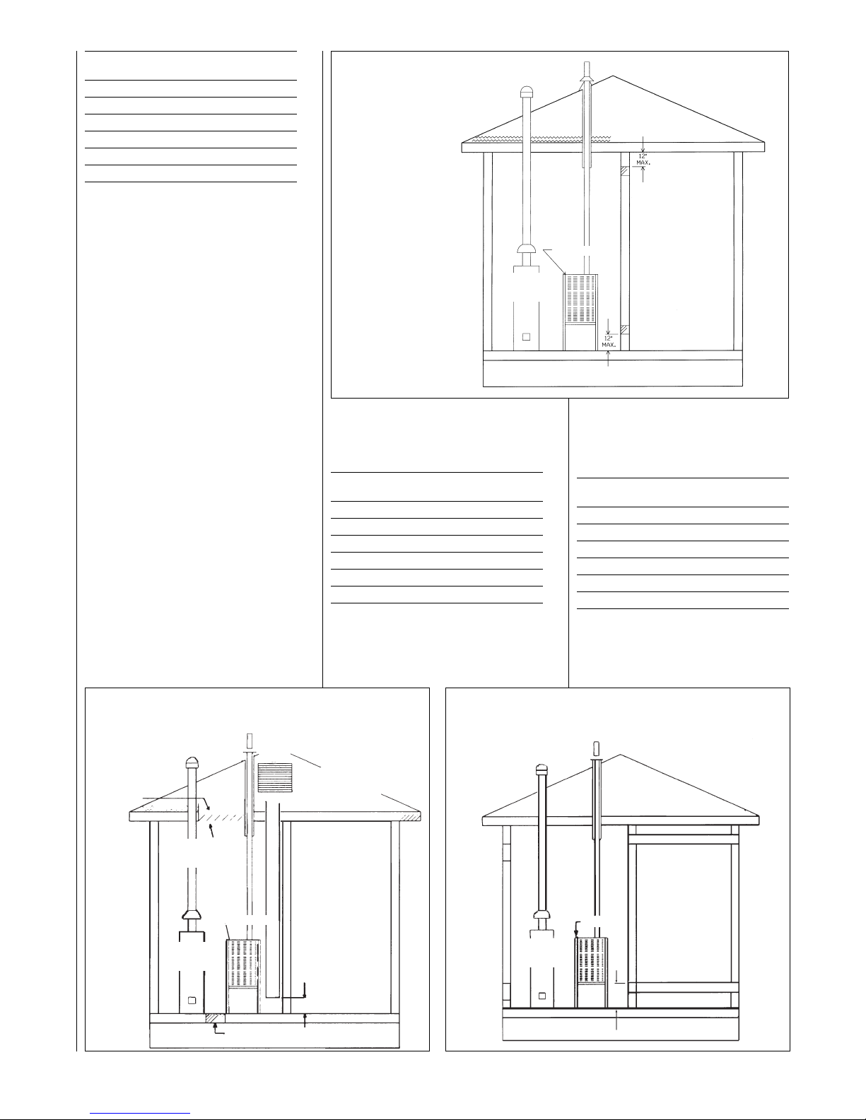
Method 1
Two permanent openings, one
located within 12 inches of the top
and one located within 12 inches
of the bottom of the enclosure,
shall be provided. The openings
shall communicate directly, or by
ducts, with the outdoors or spaces
(crawl or attic) that freely
communicate with the outdoors.
a. Where directly communicating
with the outdoors or where
communicating to the outdoors
through vertical ducts as shown in
Figure 11, each opening shall
have a minimum free area of 1
square inch for each 4,000 BTUH
of total appliance input rating in the
enclosure.
BTUH Free Area Round Pipe
Input Each Opening Size
45,000 11.25 square inches 4"
60,000 15.00 square inches 5"
75,000 18.75 square inches 5"
90,000 22.50 square inches 6"
105,000 26.25 square inches 6"
120,000 30.00 square inches 6"
b. Where communicating with
outdoors through horizontal ducts,
each opening shall have a
minimum free area of 1 square
inch for each 2,000 BTUH of total
input rating of all equipment in the
enclosure.
Here are some typical sizes.
BTUH Free Area Round Pipe
Input Each Opening Size
45,000 22.50 square inches 6"
60,000 30.00 square inches 6"
75,000 37.50 square inches 7"
90,000 45.00 square inches 8"
105,000 52.50 square inches 8"
120,000 60.00 square inches 9"
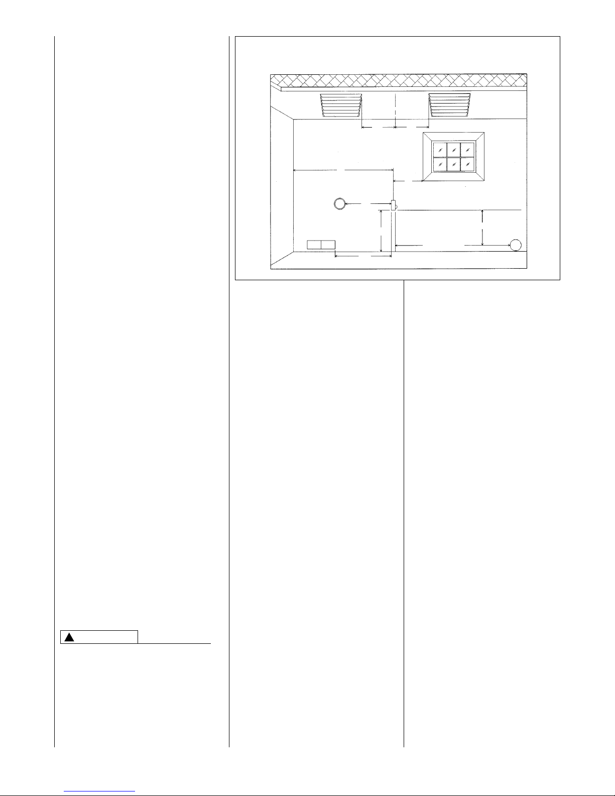
Method 2
One permanent opening, located
within 12 inches of the top of the
enclosure, shall be permitted
FIGURE 11
AIR FROM ATTIC/CRAWL SPACE
FIGURE 12
OUTSIDE AIR USING A HORIZONTAL DUCT
FIGURE 10
AIR FROM HEATED SPACE
NOTE:
EACH OPENING SHALL
HAVE A FREE AREA OF
NOT LESS THAN ONE
SQUARE INCH PER
1,000 BTU PER H0UR OF
THE
TOTAL
INPUT
RATING OF ALL
EQUIPMENT IN THE
ENCLOSURE, BUT NOT
LESS THAN 100
SQUARE INCHES.
GAS
WATER
HEATER
FURNACE
GAS
WATER
HEATER
GAS
WATER
HEATER
FURNACE
FURNACE
12" MAX.
12"
MAX.
1 SQ. INCH PER
4000 BTUH INLET AIR
OUTLET AIR 1 SQ. INCH
PER 2000 BTUH
INLET AIR 1 SQ. INCH
PER 2000 BTUH
1 SQ. INCH PER
4000 BTUH
OUTLET AIR
OUTLET AIR
IN ATTIC
MUST BE
ABOVE
INSULATION
OPTIONAL 1 SQ. INCH PER 4000 BTUH INLET AIR
VENTILATED
ATTIC GABLE OR
SOFFIT VENTS
GABLE
VENT
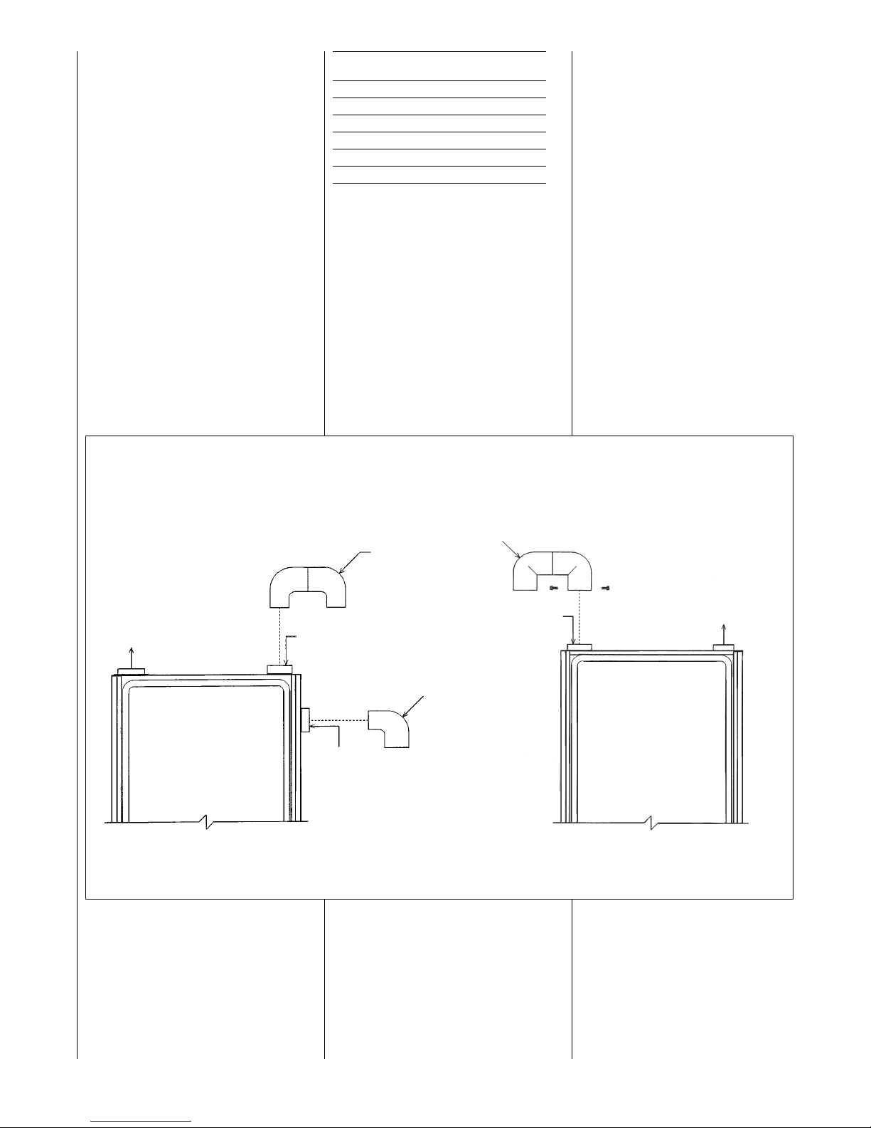
FIGURE 13
COMBUSTION AIR FITTING
UPFLOW DOWNFLOW/HORIZONTAL
2" PVC
DOUBLE
ELBOW
TOP
OPTION
EXHAUST
2" PVC ELBOW
SIDE
OPTION
2" PVC
DOUBLE
ELBOW*
COMBUSTION AIR
EXHAUST
ATTACH DOUBLE ELBOW TO INTAKE AIR
COLLAR AND SECURE WITH TWO SHEET
METAL SCREWS TO PREVENT ACCIDENTAL
BLOCKAGE OF INTAKE AIR OPENING.
➤ *NOTE: WHEN FURNACE IS INSTALLED IN
A HORIZONTAL POSITION ONLY ONE 90°
ELBOW IS REQUIRED. INSTALL THE ELBOW
SO THE OPEN END IS POINTED DOWNWARD.
ATTACH DOUBLE ELBOW TO TOP INLET
AIR OPENING OR 90° ELBOW TO SIDE
INLET AIR OPENING TO PREVENT
ACCIDENTAL BLOCKAGE OF INTAKE
OPENING. PLUG OPENING NOT USED.
16
I337 I336
where the equipment has
clearances of at least 1 inch from
the sides and back and 6 inches
from the front of the appliance.
The opening shall directly
communicate with the outdoors or
communicate through a vertical or
horizontal duct to the outdoors or
spaces (crawl or attic) that freely
communicate with the outdoors,
and shall have a minimum free
area of:
a. 1 square inch for each 3,000
BTUH of the total input rating of all
equipment located in the enclosure
and
BTUH Free Area Round Pipe
Input Each Opening Size
45,000 15.00 square inches 4"
60,000 16.67 square inches 5"
75,000 25.00 square inches 6"
90,000 30.00 square inches 6"
105,000 35.00 square inches 7"
120,000 40.00 square inches 7"
b. Not less than the sum of the
areas of all vent connectors in the
confined space.
If unit is installed where there is an
exhaust fan, sufficient ventilation
must be provided to prevent the
exhaust fan from creating a negative
pressure.
Combustion air openings must not be
restricted in any manner.
CONSULT LOCAL CODES FOR
SPECIAL REQUIREMENTS.
Return air grilles and warm air
registers must not be obstructed.
CONNECTION TO
FURNACE
IMPORTANT: When indoor
combustion air is used, the inlet air
opening at the furnace must be
protected from accidental blockage.
On upflow models, install a 90° elbow
pointing downward in the side inlet air
opening or a double elbow pointing
downward in the top inlet air opening.
On downflow/horizontal models,
install a double elbow in the top inlet
air opening. See Figure 13.
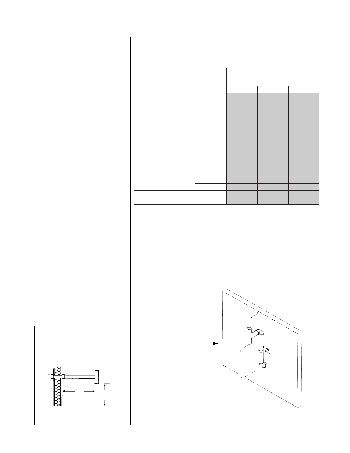
ELEVATED SINGLE PIPE ALTERNATE TEE TERMINATION
See Figure 15. The tee termination may be elevated up to 24 inches above the
wall penetration if required for anticipated snow levels. Use 2 medium-radius, 2-in.
PVC elbows and 2-in. PVC pipe, attaching the tee so it is 12 inches from the wall.
17
NON-DIRECT VENT
INSTALLATION
GUIDELINES
IMPORTANT: FAILURE TO
CORRECTLY FOLLOW ALL
VENTING GUIDELINES MAY
RESULT IN ERRATIC FURNACE
OPERATION, FREEZE-UP OF
COMBUSTION AIR OR EXHAUST
AIR PIPING OR SOOTING OF THE
FURNACE.
All exhaust piping must be installed in
compliance with Part 7, “Venting of
Equipment,” of the latest edition of the
National Fuel Gas Code NPFA54/
ANSI Z223.1-, CAN/CGA-B149, local
codes or ordinances and these
instructions.
1. Vertical piping is preferred.
2. All horizontal piping must slope
upward a minimum of
1
/4 inch
per foot of run so that
condensate drains toward the
furnace.
3. All horizontal runs must be
supported at least every 4 feet.
No sags or dips are permitted.
4.
IMPORTANT: DO NOT
COMMON VENT WITH ANY
OTHER APPLIANCE. DO NOT
INSTALL IN THE SAME CHASE
OR CHIMNEY WITH A METAL
OR HIGH TEMPERATURE
PLASTIC PIPE FROM
ANOTHER GAS OR FUELBURNING APPLIANCE
UNLESS THE REQUIRED
MINIMUM CLEARANCES TO
COMBUSTIBLES ARE
MAINTAINED BETWEEN THE
PVC PIPE AND OTHER PIPES.
5. All vent runs through unconditioned spaces where belowfreezing temperatures are
expected should be insulated
with 1-in. thick, medium-density,
foil-faced fiberglass. An
equivalent “arm-a-flex” or
FIGURE 14
TEE TERMINAL – FOR
STANDARD HORIZONTAL
SINGLE PIPE INSTALLATION
FIGURE 15
ALTERNATE HORIZONTAL
TERMINATION FOR
NON-DIRECT VENT
INSTALLATIONS
12"
FROM
24"
MAX.
PIPE
SUPPORT
STRAP
OUTSIDE
WALL
VENT
12"
12" MIN. ABOVE
GRADE OR
SNOW LEVEL
I198
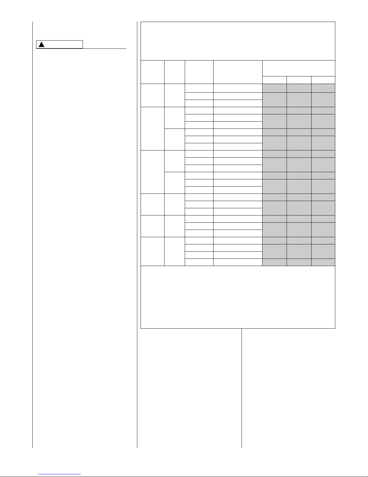
NUMBERS OF ELBOWS
45° OR 90°
Medium / Long Radius ONLY
1-2 3-4 5-6
45,000 2”
Standard 60 55 50
Alternate 55 50 45
2”
Standard 35 30 25
Alternate 30 25 20
60,000
3”
Standard 120 120 115
Alternate 120 120 110
2”
Standard 20 15 10
Alternate NR NR NR
75,000
3”
Standard 110 105 95
Alternate 80 70 65
90,000 3”
Standard 90 85 75
Alternate 60 50 45
105,000 3”
Standard 80 75 65
Alternate 50 40 35
120,000 3”
Standard 70 65 55
Alternate 40 30 25
NOTES:
1. *N.R. - NOT RECOMMENDED.
2. MAXIMUM OF 6 - 90 DEGREE ELBOWS MAY BE USED. DO NOT COUNT ELBOWS REQUIRED FOR
ALTERNATE TERMINATION. USE ONLY MEDIUM OR LONG SWEEP ELBOWS.
3.
➤ A 45° DEGREE ELBOW IS CONSIDERED ONE ELBOW.
FURNACE
INPUT
➤TABLE 1
FOR NON-DIRECT VENT APPLICATIONS - AIR FOR COMBUSTION
PROVIDED FROM INDOORS
MAXIMUM ALLOWABLE LENGTH IN FEET OF EACH EXHAUST PIPE AND INTAKE PIPE
VENT PIPE INSTALLATION
PIPE
SIZE
TERMINATION
“rub-a-tex” insulation may also be
used as long as there is no heat
tape applied to the vent pipe. For
horizontal runs where water may
collect, wrap the vent pipe with
self-regulating 3 or 5 watt heat
tape. The heat tape must be
U.L. listed and installed per the
manufacturer’s instructions.
6. The minimum vent pipe length is
5 feet.
STANDARD INSTALLATIONS
The single-pipe system requires an
exhaust pipe only. Combustion air
may be taken from the furnace
installation area or ducted to the
furnace area from the outside.
Size the exhaust pipe as specified in
Table 1. This table lists the maximum
allowable length in feet of the exhaust
pipe that may be used for all furnace
inputs as related to the number of
elbows required and the termination.
(See shaded area.)
Vertical through-the-roof installations
do not require a vent termination. Use
2-in. PVC pipe extending a minimum
of 12 inches above the anticipated
level of snow accumulation. See
exhaust pipe requirements, Figure 20.
When 3-in. vent pipe is used from
furnace to the roof, reduce it to
2 inches before penetrating the roof.
A maximum of 18 inches of 2-in. pipe
may be used below the roof.
Horizontal vent terminations require a
2-in. PVC tee positioned 12 inches
from the outside wall. See exhaust
pipe requirements, Figure 21. When
3-in. pipe is used from the furnace to
the outside wall, reduce it to 2 inches
before penetrating the wall. A
maximum of 18 inches of 2-in. pipe
may be used inside the wall.
An alternate termination may be used
as shown in Figure 15 to clear
anticipated snow levels. The tee may
be raised up to 24 inches above the
wall penetration. Use two mediumradius bend, 2-in. PVC elbows and a
length of 2-in. PVC pipe so that the
elbows are on 24-in. centers.
NON-DIRECT VENT TERMINATION
LOCATION REQUIREMENTS
MOISTURE IN THE COMBUSTION
PRODUCTS CONDENSES AS IT
LEAVES THE TERMINATION. THIS
CONDENSATE CAN FREEZE ON
EXTERIOR WALLS, UNDER THE
EAVES, AND ON SURROUNDING
OBJECTS. SOME DISCOLORATION IS TO BE EXPECTED.
HOWEVER, IMPROPER LOCATION
18
OR INSTALLATION CAN CAUSE
STRUCTURAL OR EXTERIOR
FINISH DAMAGE TO THE
BUILDING.
Non-direct venting location
requirements are slightly different in
some cases than direct venting. Install
a non-direct vent with the following
minimum clearances.
See Figure 16.
1. Locate the bottom of the vent
terminal at least 12 inches above
grade. Increase the 12-in.
minimum to keep the terminal
openings above the level of snow
accumulation, where applicable.
2. The vent shall not terminate over
public walkways or over an area
where condensate or vapor could
create a nuisance or hazard.
3. 4 feet below, 4 feet horizontally
from, or 1 foot above any door,
window soffit, under eave vent or
gravity air inlet to the building.
4. The vent terminal shall have a
minimum horizontal clearance of
4 feet from electric meters, gas
meters, regulators and relief
equipment.
5. 6 feet from an inside corner
formed by two exterior walls –
10 feet is the recommended
distance.
6. Locate it 3 feet above any forced
air inlet located within 10 feet.
Any fresh air or make-up air inlet,
such as for a dryer or furnace
area, is considered a forced air
inlet.
!
CAUTION
FIGURE 16
NON-DIRECT VENT TERMINATION CLEARANCES
I133
SOFFIT
VENTS
FRESH
AIR
INTAKE
*NOTE: FOR DISTANCES OVER 10* NO
VERTICAL RESTRICTIONS APPLY.
INSIDE
CORNER
ELECTRIC
METER
10* RECOMMENDED
12( MIN.
UP TO10**
4*
4*
3*
4*
4*
4*
6*
7. Avoid areas where dripping
condensate may cause problems,
such as above planters, patios, or
adjacent to windows where
steam may cause fogging.
In addition to the minimum clearances
listed above, the vent location should
also be governed by the following
guidelines.
1. Do not terminate under any kind
of patio or deck. If running the
vent under a deck, insulate it to
insure no condensate freezes
and blocks the pipe.
2. Do not locate on the side of a
building with prevailing winter
winds. This will help prevent
moisture from freezing on walls
and overhangs (under eaves).
3. Do not extend vent directly
through brick or masonry
surfaces. Use a rust-resistant
sheet metal or plastic backing
plate behind vent.
4. Do not locate too close to shrubs
as condensate may stunt or kill
them.
5. Minimum vertical clearances of 1
foot are recommended for
overhangs up to 1 foot horizontal.
The vertical clearance should be
increased equally for each
additional increase in horizontal
overhang to a maximum vertical
clearance of 6 feet.
6. Caulk all cracks, seams and
joints within 6 feet horizontally
and above and below vent.
19
DIRECT VENT
INSTALLATIONS
READ AND FOLLOW ALL
INSTRUCTIONS IN THIS SECTION.
FAILURE TO PROPERLY VENT
THIS FURNACE CAN CAUSE
CARBON MONOXIDE POISONING
OR AN EXPLOSION OR FIRE,
RESULTING IN PROPERTY
DAMAGE, PERSONAL INJURY
OR DEATH.
Direct vent installations require a
dedicated combustion air and venting
system. All air for combustion is taken
from the outside atmosphere and all
combustion products are discharged
to the outdoors. Therefore, no
ventilation or combustion air
openings are required.
IMPORTANT: The plastic combustion
air and venting components are of
Schedule 40 PVC. If using ABS
piping ensure that the solvent cement
is compatible for joining PVC to ABS
components or use a mechanical
connection that can withstand the
vent temperatures and are corrosion
resistant.
INSTALLATION GUIDELINES
All exhaust piping must be installed in
compliance with Part 7, “Venting of
Equipment,” of the latest edition of the
National Fuel Gas Code NPFA54/
ANSI Z223.1-, CAN/CGA-B149, local
codes or ordinances and these
instructions.
1. Vertical piping is preferred.
2. All horizontal piping must slope
upward a minimum of
1
/4 inch
per foot of run so that condensate
drains toward the furnace.
3. All horizontal runs must be
supported at least every 4 feet.
No sags or dips are permitted.
4.
IMPORTANT: DO NOT COMMON VENT WITH ANY OTHER
APPLIANCE. DO NOT INSTALL
IN THE SAME CHASE OR
CHIMNEY WITH A METAL OR
HIGH TEMPERATURE PLASTIC PIPE FROM ANOTHER
GAS OR FUEL-BURNING
APPLIANCE UNLESS THE
REQUIRED MINIMUM
CLEARANCES TO
COMBUSTIBLES ARE
MAINTAINED BETWEEN THE
PVC PIPE AND OTHER PIPES.
5. All vent runs through unconditioned spaces where belowfreezing temperatures are
expected should be insulated
with 1-in. thick, medium-density,
foil-faced fiberglass. An
equivalent “arm-a-flex” or “rub-atex” insulation may also be used
as long as there is no heat tape
applied to the vent pipe. For
horizontal runs where water may
collect, wrap the vent pipe with
self-regulating 3 or 5 watt heat
tape. The heat tape must be
!
WARNING
➤TABLE 2
FOR DIRECT VENT APPLICATIONS - AIR FOR COMBUSTION
PROVIDED FROM OUTDOORS
MAXIMUM ALLOWABLE LENGTH IN FEET OF EACH EXHAUST PIPE AND INTAKE AIR PIPE
U.L. listed and installed per the
manufacturer’s instructions.
6. The minimum vent pipe length is
5 feet.
Size the exhaust and combustion air
intake pipes as specified in Table 2.
This table lists the maximum allowable length in feet of the exhaust and
combustion air intake pipes that may
be used for all furnace inputs as
related to the number of elbows
required and the termination (see
shaded area).
FURNACE
INPUT
PIPE
SIZE
TERMINATION
VENT TERMINATION
KIT RECOMMENDED
(RXGY-D0* Kits for
Horizontal Venting Only)
1 - 2 3 - 4 5 - 6
NUMBER OF ELBOWS
45° or 90°
Medium / Long Radius ONLY
Standard RXGY-D02 65 60 55
45,000 2” Concentric RXGY-C01/RXGY-E02
55 50 45
Alternate RXGY-D02
Standard RXGY-D02 40 35 30
2” Concentric RXGY-C01/RXGY-E02
30 25 20
Alternate RXGY-D02
60,000
Standard RXGY-D03 120 120 120
3” Concentric RXGY-C01/RXGY-E02
110 105 100
Alternate RXGY-D03
Standard RXGY-D02 20 15 10
2” Concentric Not Recommended
NR NR NR
Alternate Not Recommended
75,000
Standard RXGY-D03 120 120 120
3” Concentric RXGY-C01/RXGY-E02
100 95 85
Alternate RXGY-D03
Standard RXGY-D03 110 105 95
90,000 3” Concentric RXGY-C01/RXGY-E02
50 40 35
Alternate RXGY-D03
Standard RXGY-D03 110 105 95
105,000 3” Concentric RXGY-C01/RXGY-E02
50 40 35
Alternate RXGY-D03
Standard RXGY-D03 105 100 90
120,000 3”
Concentric RXGY-C01/RXGY-E02
45 35 30
Alternate RXGY-D03
Alternate RXGY-D04 105 95 90
NOTES:
1. N.R. - NOT RECOMMENDED.
2. MAXIMUM OF 6 ELBOWS MAY BE USED. DO NOT COUNT ELBOWS IN ALTERNATE TERMINATION KIT.
MEDIUM OR LONG SWEEP ELBOWS MAY BE USED.
3. ➤ A 45 DEGREE ELBOW IS CONSIDERED ONE ELBOW.
4. CONCENTRIC TERMINATION NO. RXGY-C01 IS FOR THRU-THE-WALL VENTING.
5. CONCENTRIC TERMINATION NO. RXGY-E02 IS FOR THRU-THE-ROOF VENTING.
6. USE KITS RXGY-DO2 (2") OR RXGY-D03 (3") FOR STANDARD OR ALTERNATE THRU-THE-WALL VENTING.
7. USE KITS RXGY-D04 FOR ALTERNATE VENTING OF 120,000 BTUH UNITS WITH LONG RUNS.

20
➤ALTERNATE
TERMINATIONS
ALTERNATE HORIZONTAL
DIRECT VENT TERMINATIONS
KIT NOS. RXGY-D02, -D03
AND -D04
The combustion air and exhaust
terminations may be raised a
maximum of 60 inches above the
wall penetration to maintain the
required 12 inch clearance above
grade or snow level. See Figure 17.
Size the pipe length according to
Table 2.
IMPORTANT: The following
guidelines must be met when
extending beyond 24 inches of pipe
on the exterior of the structure:
• Size the entire vent system
according to the concentric, not
standard, termination shown in
Table 2.
COMBUSTION AIR FOR
DIRECT VENT
INSTALLATIONS
THE COMBUSTION AIR SYSTEM
DESIGNED FOR THIS FURNACE
MUST BE USED.
When this furnace is installed as a
direct vent forced air furnace, all
combustion air is supplied directly to
the burner through a special air inlet
system outlined in these instructions.
This system consists of field-supplied
Schedule 40 or 26 SDR-PVC pipe
and one of the following horizontal
vent termination kits: RXGY-D02,
RXGY-D03, RXGY-D04, RXGY-C01
or RXGY-E02.
NOTE: Schedule 40 ABS-DWV pipe
and fittings may be used as an
alternate to PVC pipe for the
combustion air inlet and vent pipes.
The combustion air for this furnace is
supplied directly from the outdoors
through the combustion air inlet
system.
When the furnace is installed in the
same space with other gas
appliances, such as a water heater,
be sure there is an adequate supply
of combustion and ventilation air for
the other appliances. Do not delete or
reduce the combustion air supply
required by the other gas appliances
in this space. See Z223.1, National
Fuel Gas Code (NFPA54) or
CAN/CGA-B149.1 and .2 for determining the combustion air requirements for gas appliances. An
unconfined space must have at least
50 cubic feet (volume) for each
1,000 BTUH of the total input of all
appliances in the space. If the open
space containing the appliances is in
a building with tight construction
(contemporary construction), outside
air may still be required for the
appliances to burn and vent properly.
Outside air openings should be sized
the same as for a confined space.
STANDARD TERMINATIONS
STANDARD VERTICAL
TERMINATIONS
COMBUSTION AIR PIPING
Use two medium-radius sweep
elbows to keep the inlet downward to
prevent entry of rain. See Figure 20
for the proper relationship of
combustion air to exhaust
termination.
STANDARD HORIZONTAL
TERMINATIONS
COMBUSTION AIR PIPING
When 3-in. pipe is used between the
furnace and outside wall, reduce it
to 2 inches before penetrating the
wall. Up to 18 inches of 2-in. pipe
may be used inside the wall.
The standard horizontal intake air
termination for all models is a 2-in.
PVC coupling with a wind deflector
vane (provided) attached. Cut a
2
1
/4-in. length of 2-in. PVC pipe.
Connect this pipe and another 2-in.
PVC coupling to the coupling at the
wall. The outer coupling must
terminate 4 inches from the wall. See
Figure 21, Detail B, for vane location.
Attach vane in vertical position with
PVC solvent.
IMPORTANT: To ensure proper
furnace operation, the supplied
vane must be installed in the
vertical position as shown in Figure
21, Detail B.
The combustion air inlet terminal
must be located with respect to the
exhaust terminal as shown in Figure
21, Detail C.
➤ IMPORTANT: All furnaces with
horizontal air intakes, except those
using horizontal concentric vent kit
RXGY-C01, must have a drain tee
assembly and trap installed as
close to the furnace as possible.
This is to drain any water that may
be in the combustion air pipe to
prevent it from entering the
furnace combustion chamber.
These parts are included in kits
RXGY-D02 (for 2-in. pipe), RXGYD03 (for 3-in. pipe) and RXGY-D04
(special for the 120,000 BTU
furnace installed with the alternate
horizontal termination). Attach the
trap to the bottom of the tee with
PVC solvent. Connect the other
end to a suitable drain, as to the
downstream of a condensate trap
on the furnace.
STANDARD VERTICAL
TERMINATIONS
EXHAUST VENT PIPING
Vertical through-the-roof vent appli-
cations do not require an exhaust
terminal. The exhaust vent must
terminate at least 12 inches above
the combustion intake air termination.
The exhaust vent for models with
inputs of 90,000 through 120,000
BTUH is 2-in. PVC pipe 120,000
BTUH models with excessively long
runs require 2
1
⁄2(. Refer to Table 2 for
proper application. This must
be reduced to 1( or 1
1
⁄2( the last
12 inches for models with inputs of
45,000 through 75,000 BTUH.
See Figure 22.
STANDARD HORIZONTAL
TERMINATIONS
EXHAUST PIPING
For direct vent systems the standard
termination is 2-in. PVC pipe
extending 12 inches from the wall for
furnaces with inputs from 90,000 to
120,000 BTUH. Install a 2-in. coupling
at the outside wall to prevent the
termination from being pushed
inward. When 3-in. pipe is used
between the furnace and outside wall,
reduce to 2 inches before penetrating
the wall. The standard termination is
1
1
/2 -in. PVC pipe extending outward
12 inches from the wall for models
with inputs of 45,000 to 75,000
BTUH. Install a 2-in. to 1
1
/2-in.
coupling at the outside wall to prevent
pushing the termination back into the
wall. See Figure 21, Detail B.
The combustion air and exhaust
terminations must be at least 12
inches above grade and must be
oriented with respect to each other as
shown in Figure 21. Refer to section
on alternate venting options when
higher snow levels are anticipated.
 Loading...