

Page 1
!
If the information in these instructions is not followed exactly, a
fire or explosion may result, causing property damage, personal
injury or death.
INSTALLATION INSTRUCTIONS
FOR UPFLOW & DOWNFLOW/HORIZONTAL HIGH
EFFICIENCY CONDENSING GAS FURNA CES
RGRA/RGRJ AND RGTA/RGTJ SERIES
92-23531-16-09
SUPERSEDES 92-23531-16-08
THESE INSTRUCTIONS ARE
INTENDED AS AN AID TO
QUALIFIED SERVICE
PERSONNEL FOR PROPER
INSTALLATION, ADJUSTMENT
AND OPERATION OF THIS
UNIT. READ THESE
INSTRUCTIONS THOROUGHLY
BEFORE ATTEMPTING
INSTALLATION OR
OPERATION. FAILURE TO
FOLLOW THESE
INSTRUCTIONS MAY RESULT
IN IMPROPER INSTALLATION,
ADJUSTMENT, SERVICE OR
MAINTENANCE, POSSIBLY
RESULTING IN FIRE,
ELECTRICAL SHOCK, CARBON
MONOXIDE POISONING,
EXPLOSION, PROPERTY
DAMAGE, PERSONAL INJURY
OR DEATH.
Do Not Destroy this Manual.
Please read carefully and keep
in a safe place for future
reference by a serviceman.
WARNING
Recognize this symbol as an indication of Important Safety Information!
!
— Do not store or use gasoline or other
flammable vapors and liquids, or other
combustible materials in the vicinity of this
or any other appliance.
— WHAT TO DO IF YOU SMELL GAS
• Do not try to light any appliance.
• Do not touch any electrical switch; do not
use any phone in your building.
• Immediately call your gas supplier from a
neighbor’s phone. Follow the gas
supplier’s instructions.
• If you cannot reach your gas supplier,
call the fire department.
• Do not return to your home until
authorized by the gas supplier or fire
department.
— DO NOT RELY ON SMELL ALONE TO
DETECT LEAKS. DUE TO VARIOUS
FACTORS, YOU MAY NOT BE ABLE TO
SMELL FUEL GASES.
• U.L. recognized fuel gas and CO
detectors are recommended in all
applications, and their installation should
be in accordance with the manufacturer’s
recommendations and/or local laws,
rules, regulations, or customs
— Improper installation, adjustment, alteration,
service or maintenance can cause injury,
property damage or death. Refer to this
manual. Installation and service must be
performed by a qualified installer, service
agency or the gas supplier.
WARNING
!
PROPOSITION 65: THIS FURNACE CONTAINS FIBERGLASS
INSULATION. RESPIRABLE PARTICLES OF FIBERGLASS ARE
KNOWN TO THE STATE OF CALIFORNIA TO CAUSE CANCER.
EXHAUST GAS FROM THIS FURNACE CONTAINS CHEMICALS,
INCLUDING CARBON MONOXIDE, KNOWN TO THE STATE OF
CALIFORNIA TO CAUSE BIRTH DEFECTS OR OTHER
REPRODUCTIVE HARM.
WARNING
!
FOR YOUR SAFETY
!
Page 2

INSTALLATION CHECK LIST
REFER TO INSTALLATION INSTRUCTIONS
GAS SUPPLY
Adequate pipe size
Correct supply pressure (during furnace operation)
Manifold pressure
No gas leaks
ELECTRICAL
115 V.A.C. supply (Single Circuit)
Polarity observed
Furnace properly grounded
Adequate wire size
FURNACE INSTALLATION
Adequate clearance to combustibles
Adequate clearance for service (at front)
DUCT STATIC PRESSURE
in. w.c. on heating speed
in. w.c. on cooling speed
Air temperature rise
CONDENSATE LINE
Trap filled with water
Vented
Sloped toward drain
Condensate drain line hoses connected
and clamped
Freeze protection (if necessary)
VENTING – DIRECT VENT
in. diameter – intake pipe
in. diameter – exhaust pipe
ft. of pipe – intake air
no. of elbows – intake air
ft. of pipe – exhaust pipe
no. of elbows – exhaust pipe
TERMINATIONS – DIRECT VENT
VERTICAL
Intake – 12" min. above roof/snow level
Correct relationship – exhaust to intake
VERTICAL – CONCENTRIC (RXGY-E02)
Intake – 12" min. above roof/snow level
HORIZONTAL – STANDARD (RXGY-D02, -D03)
Correct relationship – exhaust to intake
12" min. above grade/snow level
HORIZONTAL – ALTERNATE (RXGY-D02, -D03 OR -D04)
Correct relationship – exhaust to intake
Above anticipated snow level
HORIZONTAL – CONCENTRIC (RXGY-C01)
12" min. above grade/snow level
Intake “Y” rotated above center
Exhaust sloped toward furnace
VENTING – NON-DIRECT VENT
in. diameter – exhaust pipe
ft. of pipe – exhaust
no. of elbows
TERMINATION – NON-DIRECT VENT
VERTICAL
12" min. above roof/snow level
HORIZONTAL – STANDARD
12" min. above grade/snow level
HORIZONTAL – ALTERNATE
Above anticipated snow level
2
Page 3

3
IMPORTANT: TO INSURE PROPER INSTALLATION AND OPERATION OF
THIS PRODUCT, COMPLETELY READ ALL INSTRUCTIONS PRIOR TO
ATTEMPTING TO ASSEMBLE, INSTALL, OPERATE, MAINTAIN OR REPAIR
THIS PRODUCT. UPON UNPACKING OF THE FURNACE, INSPECT ALL
PARTS FOR DAMAGE PRIOR TO INSTALLATION AND START-UP.
CONTENTS
Safety Precautions...................................................................................................1
Installation Check List ..............................................................................................2
Location Requirements and Considerations............................................................5
Venting and Combustion Air Piping .......................................................................12
Combustion and Ventilation Air..............................................................................14
Vent Pipe Installation..............................................................................................17
Condensate Drain/Neutralizer................................................................................27
Converting Downflow to Horizontal........................................................................29
Gas Supply and Piping...........................................................................................31
Electrical Wiring......................................................................................................35
Accessories............................................................................................................37
Start-Up Procedures...............................................................................................44
Air Flow...................................................................................................................46
Maintenance...........................................................................................................50
Troubleshooting......................................................................................................53
Wiring Diagrams.....................................................................................................59
➤ Installation Instructions are updated on a regular basis. This is done as
product changes occur or if new information becomes available. In this
publication, an arrow (➤) denotes changes from the previous edition or additional
new material.
Page 4
GENERAL INFORMATION
The RGRA/RGRJ and RGTA/RGTJ
series furnaces are design-certified
by AGA/CGA for use with natural and
propane gases as follows:
1. As non-direct vent central forced
air furnaces taking combustion
air from the installation area or
using air ducted from the outside.
2. As direct vent central forced air
furnaces with all combustion air
supplied directly to the furnace
burners through a special air
intake system outlined in these
instructions.
4
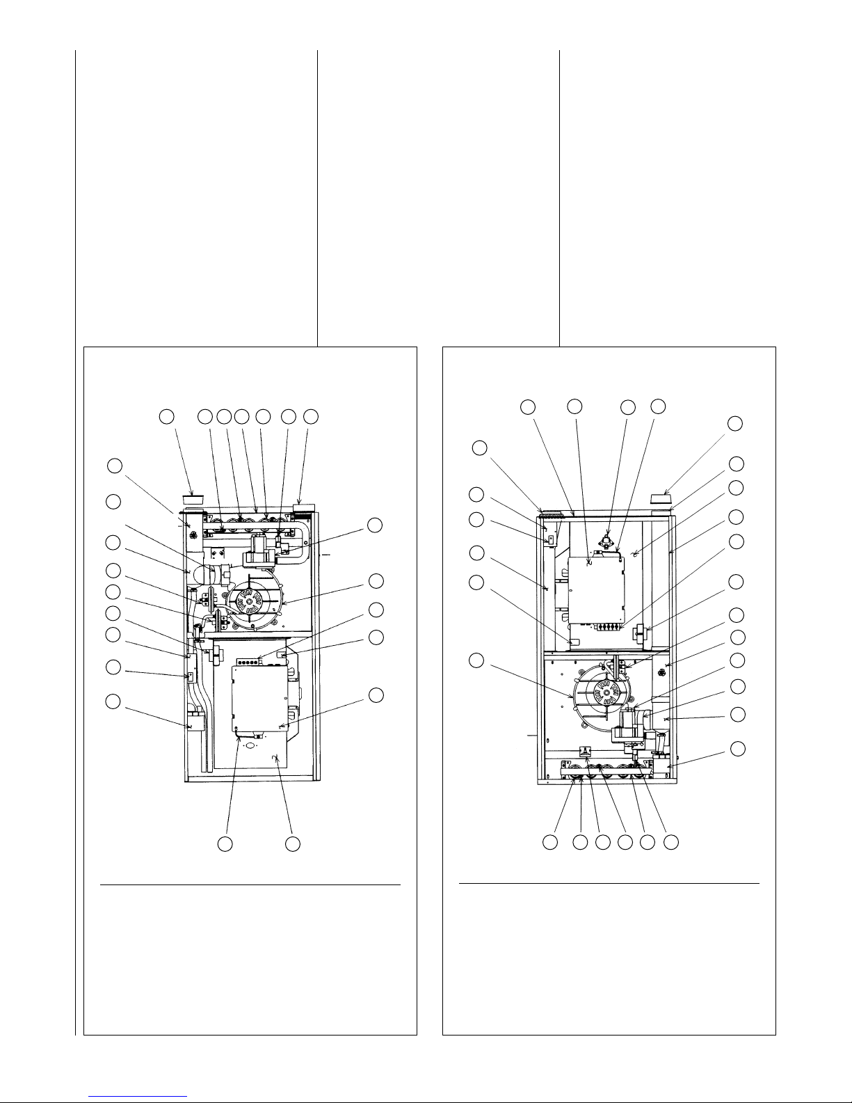
FIGURE 1
UPFLOW FURNACE
FIGURE 2
DOWNFLOW/HORIZONTAL FURNACE
Install this furnace in accordance with
the American National Standard
Z223.1 – latest edition entitled
“National Fuel Gas Code” (NFPA54)
and requirements or codes of the
local utilities or other authorities
having jurisdiction. This is available
from the following:
National Fire Protection
Association, Inc.
Batterymarch Park
Quincy, MA 02269
American Gas Association
1515 Wilson Blvd.
Arlington, VA 22209
Install units in Canada in accordance
with CAN/CGA-B149, local
installation codes and authorities
having jurisdiction. CAN/CGA-B149 is
available from:
Canadian Gas Association
55 Scarsdale Road
Don Mills, Ontario, Canada M3B, 2R3
2425262728
ITEM ITEM
NO. PART NAME NO. PART NAME
1 INDUCED DRAFT BLOWER 15 LOW VOLTAGE TERMINAL
2 CAPACITOR 16 TRANSFORMER
3 INLET AIR CHASE 17 PRESSURE SWITCH
4 DOOR SWITCH 18 OUTLET AIR PIPE
5 JUNCTION BOX 19 GAS VALVE
6 INLET PIPE CONNECTOR 20 CONNECTOR
7 TOP PLATE 21 EXHAUST TRANSITION
8 ELECTRICAL BOX 22 CONDENSATE TRAP
9 AUXILLIARY LIMIT 23 IGNITER
10 CONTROL BOX COVER GROUND 24 MANIFOLD
11 VENT CAP PLUG 25 OVERTEMPERATURE SWITCH
12 EXHAUST CONNECTION 26 ROLLOUT SWITCH
13 BLOWER 27 SENSOR
14 EXHAUST PIPE EXTENSION 28 BURNER
ITEM ITEM
NO. PART NAME NO. PART NAME
1 CONDENSATE TRAP 13 TOP PLATE
2 DOOR SWITCH 14 BURNER
3 JUNCTION BOX 15 IGNITER
4 TRANSFORMER 16 COMBUSTION AIR INLET
5 BLOCKED DRAIN PRESSURE SWITCH 17 GAS VALVE
6 MAIN PRESSURE SWITCH 18 INDUCED DRAFT BLOWER
7 EXHAUST TRANSITION 19 LOW VOLTAGE TERMINAL
8 CONNECTOR 20 CAPACITOR
9 OUTLET AIR PIPE 21 ELECTRICAL BOX
10 VENT CAP PLUG 22 BLOWER
11 SENSOR 23 CONTROL BOX
12 OVERTEMPERATURE SWITCH
COVER GROUND
1
2
3
4
5
6
7
8
9
10
11
12
13
14
15
16
17
18
19
20
21
22
23
1
2
3
4
5
6
7
8
9
10 11 12 13 14 15 16
17
18
19
20
21
2223
GAS INLET
OPTIONAL
COMBUSTION
AIR INLET
I409 I409
GAS
INLET
PVC
PVC
Page 5
GENERAL INFORMATION
1.
IMPORTANT: If furnace
operation is required during
construction, and air ladened
with corrosive compounds such
as chlorine and fluorine are
present, provisions must be
taken to provide clean outdoor
combustion and ventilation air to
the furnace. Compounds of
chlorine and fluorine, when
burned with combustion air, form
acids which will cause corrosion
of a heat exchanger. Some of
these compounds are found in
paneling, dry wall, tile adhesives,
paints, stains and varnishes,
solvents and masonry curing and
cleaning materials.
DO NOT INSTALL THIS FURNACE
IN A MOBILE HOME!! This furnace
is not approved for installation in a
mobile home. Doing so could cause
FIRE, PROPERTY DAMAGE,
PERSONAL INJURY OR DEATH.
WHEN THIS FURNACE IS
INSTALLED IN A RESIDENTIAL
GARAGE, IT MUST BE INSTALLED
SO THE BURNERS AND IGNITION
SOURCE ARE LOCATED NO LESS
THAN 18 INCHES ABOVE THE
FLOOR. THIS IS TO PREVENT
THE RISK OF IGNITING FLAMMABLE VAPORS WHICH MAY
BE PRESENT IN A GARAGE.
ALSO, THE FURNACE MUST BE
LOCATED OR PROTECTED TO
AVOID PHYSICAL DAMAGE BY
VEHICLES. FAILURE TO FOLLOW
THESE WARNINGS CAN CAUSE A
FIRE OR EXPLOSION, RESULTING
IN PROPERTY DAMAGE,
PERSONAL INJURY OR DEATH.
5
2.
IMPORTANT: If installing the
unit over a finished ceiling or
living area, be certain to install
an auxiliary condensate drain
pan under the entire unit. This
auxiliary drain pan should extend
under any evaporator coil
installed with the furnace.
3.
IMPORTANT: If using a cooling
evaporator coil with this
furnace:
a. be sure the air passes over
the heat exchanger before
passing over the cooling
coil. The cooled air passing
over the warm ambient air
inside the heat exchanger
tubes can cause
condensation inside the tubes
resulting in corrosion and
eventual failure.
b. install a parallel duct system
to divert all the air from the
furnace allowing it to pass
over the cooling coil only. Use
dampers or other means to
prevent chilled air from
passing over the heat
exchanger.
If these are manual dampers, they
must be equipped to prevent heating
or cooling operation unless the
damper is in the full heat or cool
position.
!
WARNING
!
WARNING
4.
IMPORTANT: Install the
furnace level. If it is not level,
condensate cannot drain
properly, possibly causing
furnace shut down.
NOTE: These furnaces are approved
for installation in attics, as well as
alcoves, utility rooms, closets and
crawlspaces. Provisions must be
made to prevent freezing of
condensate.
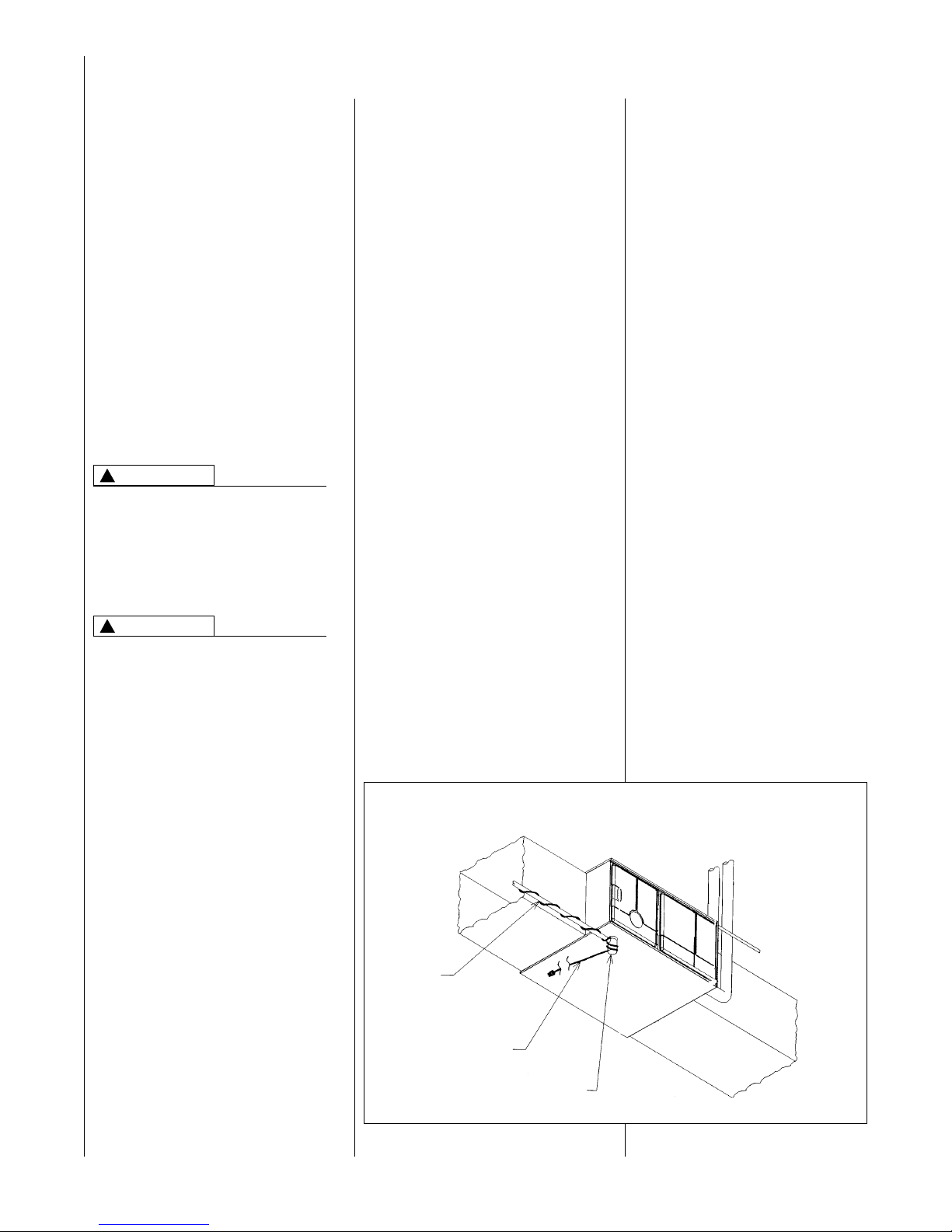
5.
IMPORTANT: If this furnace is
installed in a garage, attic
and/or any unconditioned
space, install a self-regulating
heat tape around the
condensate trap and along the
entire length of the condensate
drain in the unconditioned
space. See Figure 3.
When the condensing horizontal
gas furnace is installed in an
unconditioned space where the
temperature would be capable of
reaching close to or below 32°F
(0°C). A SELF-REGULATING
HEAT TAPE IS REQUIRED ON
THE CONDENSATE DRAIN,
ALONG WITH AN INSULATION
WRAP. The heat tape should
meet the following requirements:
LOCATION REQUIREMENTS AND CONSIDERATIONS
FIGURE 3
HORIZONTAL FURNACE W/HEAT TAPE ON CONDENSATE TRAP
DRAIN
PIPE
HEAT
TAPE
TRAP
I526
Page 6
6
a. The heat tape must be UL
listed.
b. The heat tape must be
installed per the
manufacturer’s instructions for
the entire length of drain pipe
in the unconditioned space.
c. The heat tape should be rated
at 5 or 6 watts per foot at
120V.
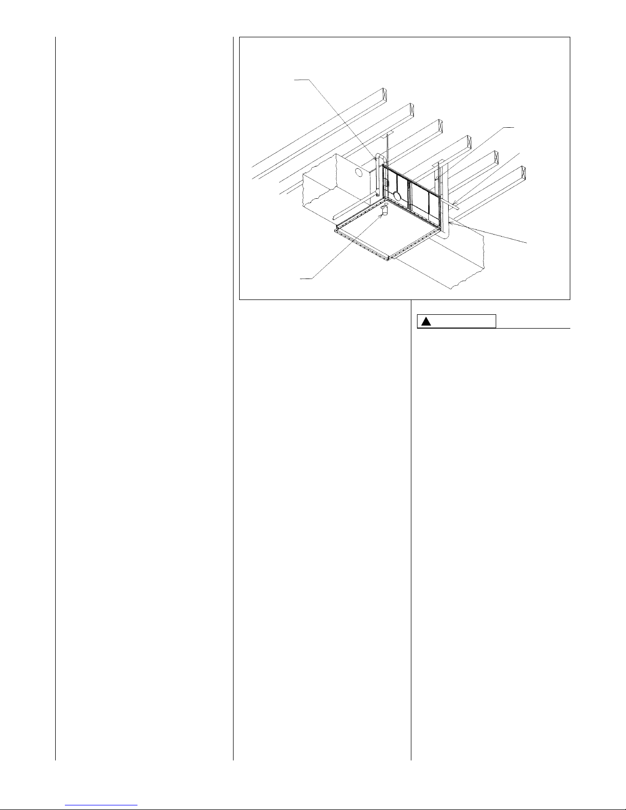
IMPORTANT: Support this unit
when installed. Since this
furnace is suitable for attic or
crawl space installation, it may
be installed on combustible wood
flooring or by using support
brackets. See Figure 4.
6.
IMPORTANT: If installing in a
utility room, be sure the door
is wide enough to:
a. allow the largest part of the
furnace to pass; or
b. allow any other appliance
(such as a water heater)
to pass.
7. IMPORTANT: This furnace is
not approved or recommended
for installation on its back,
with access doors facing
upwards.
CLEARANCE ACCESSIBILITY
The design of forced air furnaces with
input ratings as listed in the tables
under Figures 6, 7 and 8 are certified
by the AGA Laboratories and CGA
Laboratories for the clearances to
combustible materials shown in
inches.
FIGURE 4
HORIZONTAL FURNACE INSTALLED W/SUPPORT BRACKETS
GAS
PIPE
TRAP
EXHAUST
FAN
ELECTRICAL
CONDUIT
INTAKE
VENT
See name/rating plate and clearance
label for specific model number and
clearance information.
Service clearance of at least 24
inches is recommended in front of
all furnaces.
FOR PURPOSES OF SERVICING
THIS APPLIANCE, ACCESSIBILITY
CLEARANCES, WHERE GREATER,
MUST TAKE PRECEDENCE OVER
FIRE PROTECTION CLEARANCES.
UPFLOW AND HORIZONTAL
FURNACES ARE DESIGNCERTIFIED FOR INSTALLATION
ON COMBUSTIBLE FLOORS.
NOTE, HOWEVER, THAT FURNACES MUST NOT BE INSTALLED
DIRECTLY ON CARPETING, TILE
OR OTHER COMBUSTIBLE
MATERIAL OTHER THAN WOOD
FLOORING. INSTALLATION ON A
COMBUSTIBLE MATERIAL CAN
RESULT IN FIRE, CAUSING
PROPERTY DAMAGE, PERSONAL
INJURY OR DEATH.
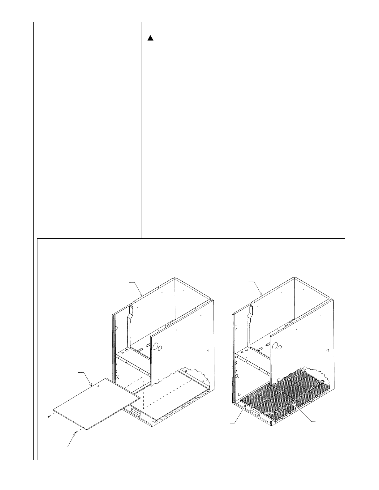
Upflow furnaces are shipped with a
bottom closure panel installed. When
bottom return air is used, remove the
panel by removing the two screws
attaching the panel to the front base
angle. See Figure 5.
!
WARNING
I522
Page 7
7
SITE SELECTION
1. Select a site in the building near
the center of the proposed, or
existing, duct system.
2. Give consideration to the vent
system piping when selecting the
furnace location. Be sure the
venting system can get from the
furnace to the termination with
minimal length and elbows.
3. Locate the furnace near the
existing gas piping. Or, if running
a new gas line, locate the
furnace to minimize the length
and elbows in the gas piping.
4. Locate the furnace to maintain
proper clearance to combustibles
as shown in the following tables.
!
WARNING
COMBUSTIBLE MATERIAL MUST
NOT BE PLACED ON OR AGAINST
THE FURNACE JACKET. THE
AREA AROUND THE FURNACE
MUST BE KEPT CLEAR AND FREE
OF ALL COMBUSTIBLE
MATERIALS INCLUDING GASOLINE AND OTHER FLAMMABLE
VAPORS AND LIQUIDS.
PLACEMENT OF COMBUSTIBLE
MATERIALS ON, AGAINST OR
AROUND THE FURNACE JACKET
CAN CAUSE AN EXPLOSION OR
FIRE RESULTING IN PROPERTY
DAMAGE, PERSONAL INJURY OR
DEATH. THE HOMEOWNER
SHOULD BE CAUTIONED THAT
THE FURNACE AREA MUST NOT
BE USED AS A BROOM CLOSET
OR FOR ANY OTHER STORAGE
PURPOSES.
FIGURE 5
BOTTOM PANEL REMOVAL
JACKET ASSEMBLY
SOLID BOTTOM
NOTE:
BACK FLANGE OF SOLID BOTTOM FITS
UNDERNEATH JACKET. SIDES AND FRONT
FLANGES FIT OVER FLANGES ON JACKET.
SCREW
(2) REQ’D.
JACKET ASSEMBLY
FILTER
FILTER
ROD
SOLID BOTTOM REMOVAL
FILTER & ROD LOCATION
ADS 5422-01
Page 8
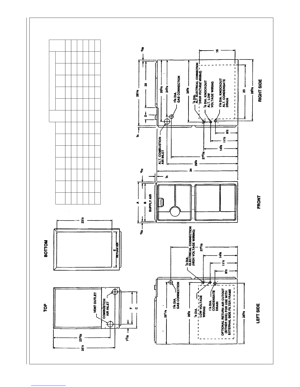
FIGURE 6
CLEARANCE TO COMBUSTIBLES, UPFLOW UNITS
8
UPFLOW MODELS MINIMUM CLEARANCE (IN.)
LEFT RIGHT SHIP
MODEL A B C D E F
SIDE SIDE
BACK TOP FRONT VENT
WGTS
04 17
1
/2 16
11
/32 15
5
/8 21513
25
/32 00012*0 111
06 17
1
/2 16
11
/32 15
5
/8 21513
25
/32 00012*0 117
07 17
1
/2 16
11
/32 15
5
/8 21513
25
/32 00012*0 123
09 21 19
27
/32 19
1
/8 218
1
/217
9
/32 00012*0 148
10 21 19
27
/32 19
1
/8 218
1
/217
9
/32 00012*0 152
12 24
1
/2 23
11
/32 22
5
/8 22220
25
/32 00012*0 160
I392
➤*A service clearance of at least 24 inches is recommended in front of all furnaces.
Page 9
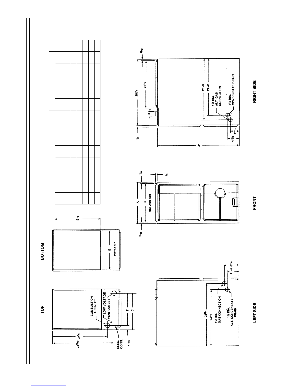
FIGURE 7
CLEARANCE TO COMBUSTIBLES, DOWNFLOW UNITS
9
DOWNFLOW MODELS MINIMUM CLEARANCE (IN.)
LEFT RIGHT SHIP
MODEL A B C D E F
SIDE SIDE
BACK TOP FRONT VENT
WGTS
04 17
1
/2
16
11
/32
15
5
/8
216
5
/8
13
7
/8
00012*0 111
06 17
1
/2 16
11
/32 15
5
/8 216
5
/813
7
/8 00012*0 117
07 17
1
/
2 16
11
/
32 15
5
/
8 216
5
/
813
7
/
8 00012*0 123
09 21 19
27
/
32 19
3
/
16 220
1
/
817
3
/
8 00012*0 148
10 21 19
27
/
32 19
3
/
16 220
1
/
817
3
/
8 00012*0 152
12 24
1
/
2 23
11
/
32 22
5
/
8 223
5
/
820
7
/
8 00012*0 160
I393
➤*A service clearance of at least 24 inches is recommended in front of all furnaces.
Page 10
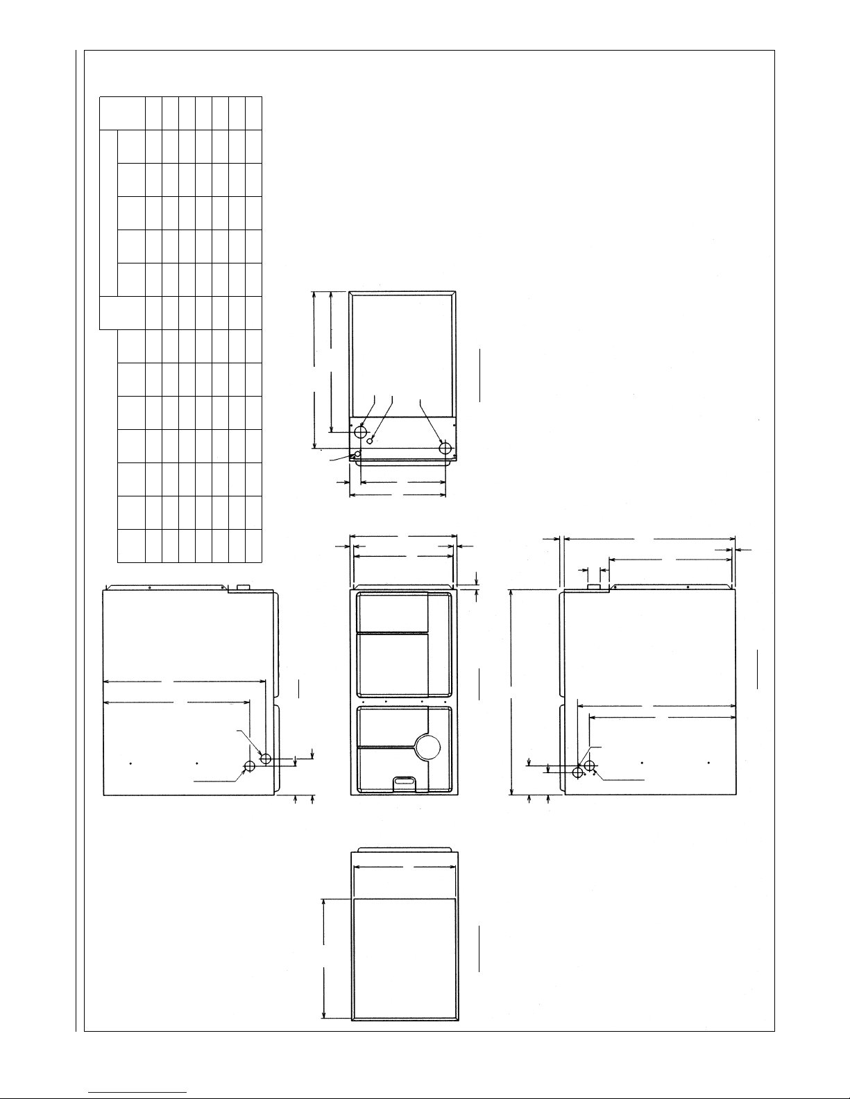
➤ FIGURE 8
CLEARANCE TO COMBUSTIBLES, HORIZONTAL UNITS
DOWNFLOW MODELS MINIMUM CLEARANCE (IN.)
LEFT RIGHT SHIP
MODEL A B C D E F
SIDE SIDE
BACK TOP FRONT VENT
WGTS
04 17
1
/2 16
11
/32 15
5
/8 216
5
/813
7
/8 00012*0 111
06 17
1
/2 16
11
/32 15
5
/8 216
5
/813
7
/8 00012*0 117
07 17
1
/2 16
11
/32 15
5
/8 216
5
/813
7
/8 00012*0 123
07 21 19
27
/32 19
3
/16 220
1
/817
3
/8 00012*0 123
09 21 19
27
/32 19
3
/16 220
1
/817
3
/8 00012*0 148
10 21 19
27
/32 19
3
/16 220
1
/817
3
/8 00012*0 152
12 24
1
/2 23
11
/32 22
5
/8 223
5
/820
7
/8 00012*0 160
10
I520
*A service clearance of at least 24 inches is recommended in front of all furnaces.
1
5
⁄8 DIA.
ALT. CONDENSATE
DRAIN
1
5
⁄8 DIA.
GAS
CONNECTION
TOP
LEFT SIDE FRONT
BOTTOM
RIGHT SIDE
4
13
⁄16
6
1
⁄64
24
1
⁄16
19
7
⁄8
23
31
⁄32
1
13
⁄16
34
4
13
⁄16
25
3
⁄32
D
28
1
⁄16
20
1
⁄18
19
⁄32
24
1
⁄16
3
⁄4
3
11
⁄16
1
5
⁄8 DIA.
ALT. GAS
CONNECTION
1
5
⁄8 DIA.
CONDENSATE
DRAIN
COMBUSTION
AIR INLET
LOW VOLTAGE
RETURN
AIR
VENT OUTLET
22
3
⁄32
ELECT.
CONN.
19
⁄32
19
⁄32
3
⁄4
E
B
A
C
F
SUPPL
Y
26
11
⁄16
Page 11
11
DUCTING
Proper air flow is required for the
correct operation of this furnace.
Too little air flow can cause erratic
operation and can damage the heat
exchanger. The duct system must
carry the correct amount of air for
heating and cooling if summer air
conditioning is used.
Size the ducts according to
acceptable industry standards and
methods. The total static pressure
drop of the air distribution system
should not exceed 0.5" w.c.
NEVER ALLOW THE PRODUCTS
OF COMBUSTION FROM THE
FLUE TO ENTER THE RETURN AIR
DUCTWORK OR THE
CIRCULATED AIR SUPPLY. ALL
RETURN DUCTWORK MUST BE
ADEQUATELY SEALED AND
SECURED TO THE FURNACE
WITH SHEET METAL SCREWS;
AND JOINTS, TAPED. ALL OTHER
DUCT JOINTS MUST BE SECURED
WITH APPROVED CONNECTIONS
AND SEALED AIRTIGHT. WHEN AN
UPFLOW FURNACE IS MOUNTED
ON A PLATFORM WITH RETURN
THROUGH THE BOTTOM, IT MUST
BE SEALED AIRTIGHT BETWEEN
THE FURNACE AND THE RETURN
AIR PLENUM. THE FLOOR OR
PLATFORM MUST PROVIDE
SOUND PHYSICAL SUPPORT OF
THE FURNACE WITHOUT
SAGGING, CRACKS, OR GAPS,
AROUND THE BASE, PROVIDING A
SEAL BETWEEN THE SUPPORT
AND THE BASE.
FAILURE TO PREVENT
PRODUCTS OF COMBUSTION
FROM BEING CIRCULATED INTO
THE LIVING SPACE CAN CREATE
POTENTIALLY HAZARDOUS
CONDITIONS, INCLUDING
CARBON MONOXIDE POISONING
THAT COULD RESULT IN
PERSONAL INJURY OR DEATH.
DO NOT, UNDER ANY
CIRCUMSTANCES, CONNECT
RETURN OR SUPPLY DUCTWORK
TO OR FROM ANY OTHER HEAT
PRODUCING DEVICE SUCH AS A
FIREPLACE INSERT, STOVE, ETC.
DOING SO MAY RESULT IN FIRE,
CARBON MONOXIDE POISONING,
EXPLOSION, PERSONAL INJURY
OR PROPERTY DAMAGE.
IMPORTANT: Some high efficiency
filters have a greater than normal
resistance to air flow. This can
adversely affect furnace operation.
BE SURE TO CHECK AIR FLOW if
using any filter other than the factoryprovided filter.
UPFLOW UNITS
1. Position the unit to minimize long
runs of duct or runs of duct with
many turns and elbows.
2. Open the return air compartment.
a. If using side or back return air,
do not remove the bottom
base.
b. Cut an opening in the side or
back. The opening should
be cut the full width of the
knockouts on the unit.
c. Remove the bottom base if
using bottom return air.
NOTE: Where the maximum air flow
is 1800 CFM or more, both sides or
the bottom must be used for return
air.
3. Connect the return duct or return
air cabinet to the unit. Make the
connection air tight to prevent
entraining combustion gases
from an adjacent fuel-burning
appliance.
4. Be sure to have adequate
space for the unit filter.
NOTE: DO NOT take return air
from bathrooms, kitchens,
furnace rooms, garages, utility or
laundry rooms, or cold areas.
5. If summer air conditioning is
desired, position the indoor coil
on the top of the unit. Insure that
no air can bypass this coil.
6. Connect the supply air plenum to
the furnace plenum opening.
IMPORTANT: If a flexible duct
connector must be used, it
MUST
be rated for a minimum
temperature of 250
°F.
continuous.
DOWNFLOW UNITS
1. Position the unit to minimize long
runs of duct or runs of duct with
many turns and elbows.
2. If summer air conditioning is
desired, position the indoor coil
on the bottom of the unit. Insure
that no air can bypass this coil.
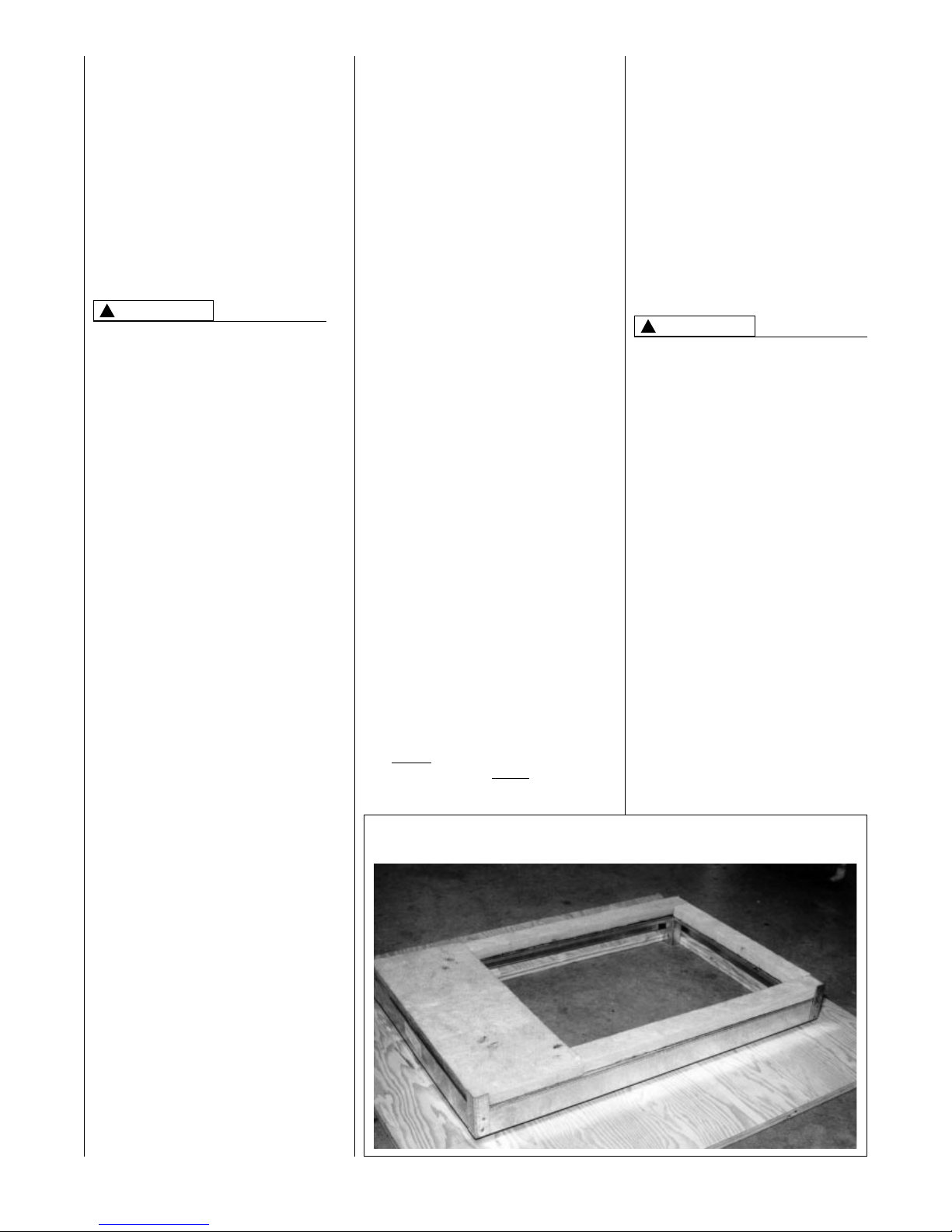
3. If installing on a combustible floor
and not using an air conditioning plenum, install the special
non-combustible floor base. See
Figure 9.
THE DOWNFLOW FURNACE
DESIGN IS CERTIFIED FOR
INSTALLATION ON A NONCOMBUSTIBLE FLOOR. USE THE
SPECIAL BASE SPECIFIED ON
THE FURNACE CLEARANCE
LABEL. FAILURE TO INSTALL THE
SPECIAL BASE MAY RESULT IN
FIRE, PROPERTY DAMAGE,
PERSONAL INJURY OR DEATH.
THIS SPECIAL BASE IS SHIPPED
FROM THE FACTORY AS AN
ACCESSORY.
4. Connect the furnace to the
supply air plenum.
5. Connect the return air ducting to
the return air opening at the top
of the unit. Make the connection
air tight to prevent entraining
combustion gases from an
adjacent fuel-burning appliance.
6. Be sure to have adequate
space for the unit filter.
NOTE: DO NOT take return air
from bathrooms, kitchens,
furnace rooms, garages, utility or
laundry rooms, or cold areas.
!
WARNING
!
WARNING
FIGURE 9
COMBUSTIBLE FLOOR BASE
Page 12
12
GENERAL INFORMATION
READ AND FOLLOW ALL INSTRUCTIONS IN THIS SECTION.
FAILURE TO PROPERLY VENT
THIS FURNACE CAN CAUSE
CARBON MONOXIDE POISONING
OR AN EXPLOSION OR FIRE,
RESULTING IN PROPERTY
DAMAGE, PERSONAL INJURY
OR DEATH.
This furnace removes both sensible
and latent heat from the combustion
flue gases. Removal of latent heat
results in condensation of flue gas
water vapor. This condensed water
vapor drains from the secondary heat
exchanger and out of the unit into a
drain trap.
When installed as a non-direct vent
furnace, only exhaust piping is
required and inside combustion air
may be used. Refer to section on
“
COMBUSTION & VENTILATION AIR
FOR FURNACE INSTALLATIONS.”
Direct vent installations require a
dedicated combustion air and venting
system. All air for combustion is taken
from the outside atmosphere and all
combustion products are discharged
to the outdoors.
The combustion air and vent pipe
fittings must conform to American
National Standards Institute (ANSI)
and American Society for Testing
Materials (ASTM) standards
D1785 (Schedule 40 PVC), D2665
(PVC-DWV), D2241 (SDR-21 and
SDR26-26 PVC), D2661 (ABS-DWV)
or F628 (Schedule 40 ABS-DWV).
In Canada all combustion air and vent
pipe must be CSA- or ULC-certified
Schedule 40 PVC, PVC-DWV or
ABS-DWV.
IMPORTANT: The plastic combustion
air and venting components are of
Schedule 40 PVC. If using ABS
piping, ensure that the solvent
cement is compatible for joining
PVC to ABS components or use a
mechanical connection that can
withstand the vent temperatures and
are corrosion resistant.
NOTE: Schedule 40 ABS-DWV pipe
and fittings may be used as an
alternate to PVC pipe for the
combustion air inlet and vent pipes.
NOTE: Cellular core PVC is also
approved for use. It must be schedule
40PVC-DWV cellular pipe for nonpressure applications and
manufactured under ASTM F-891.
OVERTEMPERATURE
SAFETY SWITCHES
Furnaces are equipped with safety
switches in the control compartment
to protect against overtemperature
conditions caused by inadequate
combustion air supply. The switches
for the upflow and downflow models
are located in the burner
compartment. If a switch is tripped it
must be manually reset.
DO NOT JUMPER THESE
DEVICES! IF ONE OF THESE
SWITCHES SHOULD TRIP, A
QUALIFIED INSTALLER, SERVICE
AGENCY OR THE GAS SUPPLIER
MUST BE CALLED TO CHECK
AND/OR CORRECT FOR
ADEQUATE COMBUSTION AIR
SUPPLY. DO NOT RESET THE
SWITCHES WITHOUT TAKING
CORRECTIVE ACTION TO ASSURE
THAT AN ADEQUATE SUPPLY OF
COMBUSTION AIR IS MAINTAINED
UNDER ALL CONDITIONS OF
OPERATION. FAILURE TO DO SO
CAN RESULT IN CARBON
MONOXIDE POISONING OR
DEATH. IF THIS UNIT IS MOUNTED
IN A CLOSET, THE DOOR MUST
BE CLOSED WHEN MAKING THIS
CHECK.
REPLACE THESE SWITCHES
ONLY WITH THE IDENTICAL
REPLACEMENT PART.
EXISTING VENT SYSTEMS
When the installation of this furnace
replaces an existing furnace that is
removed from a vent system serving
other appliances, the vent system is
likely to be too large to properly vent
the remaining attached appliances.
The following steps should be
followed with each appliance
remaining connected to the original
common vent system. Place the
appliance to be tested in operation,
while the other appliances remaining
connected to the common vent
system are not in operation. Test the
operation of each appliance
individually by the following method.
1. Permanently seal any unused
openings in the common venting
system.
2. Visually inspect the venting
system for proper size and
horizontal pitch and determine
that there is no blockage,
restriction, leakage, corrosion or
other deficiencies which could
cause an unsafe condition.
3. If practical, close all building
doors, windows and all doors
between the space where the
appliances remaining connected
to the common venting system
are located.
Turn on clothes dryers and any
appliance not connected to the
common venting system. Turn on
any exhaust fans, such as range
hoods and bathroom exhausts,
so they will operate at maximum
speed. Do not operate a summer
exhaust fan. Close fireplace
dampers.
VENTING AND COMBUSTION AIR PIPING
!
WARNING
!
WARNING
HORIZONTAL UNIT
IMPORTANT: THIS FURNACE MAY
ONLY BE INSTALLED SO AS
WHEN FACING THE FRONT OF
THE FURNACE, SUPPLY AIR IS
DISCHARGED ON THE LEFT HAND
SIDE.
1. Position the unit to minimize long
runs or runs with many turns and
elbows.
2. If summer air conditioning is
desired, position the indoor coil
on the left end of the unit. Insure
that no air can bypass this coil.
3. Connect the furnace to the
supply air plenum.
4. Connect the return air ducting to
the return air opening at the right
end of the unit. Make the
connection air tight to prevent
entraining combustion gases
from an adjacent fuel-burning
appliance.
5. Be sure to have adequate
space for the unit filter.
NOTE: DO NOT take return air
from bathrooms, kitchens,
furnace rooms, garages, utility or
laundry rooms, or cold areas.
Page 13

CEMENTING JOINTS
Properly seal all joints in the PVC
vent using the following materials and
procedures.
PVC CLEANER-PRIMER AND
PVC MEDIUM-BODY SOLVENT
CEMENT
IMPORTANT:
After cutting pipe,
remove all ragged edges and burrs.
This is important to prevent reduction
in pressure drop throughout the
system.
1. Cut pipe end square. Chamfer
edge of pipe. Clean fitting socket
and pipe joint area of all dirt,
grease and moisture.
2. After checking pipe and socket
for proper fit, wipe socket and
pipe with cleaner-primer. Apply
a liberal coat of primer to inside
surface of socket and outside of
pipe. Read instructions included
with the primer for proper
application.
3. Apply a thin coat of cement
evenly in the socket. Quickly
apply a heavy coat of cement to
the pipe end and insert pipe into
fitting with a slight twisting
movement until it bottoms out.
NOTE: Cement must be fluid; if
not, recoat.
4. Hold the pipe in the fitting for 30
seconds to prevent the tapered
socket from pushing the pipe out
of the fitting.
5. Wipe all excess cement from the
joint with a rag. Allow 15 minutes
before handling. Cure time varies
according to fit, temperature and
humidity.
NOTE: Stir the solvent cement
frequently while using. Use a natural
bristle brush or the dauber supplied
with the can. The proper brush size is
one inch.
IMPORTANT: For Proper Installation
DO NOT use solvent cement that
has become curdled, lumpy or
thickened.
DO NOT thin. Observe shelf
precautions printed on containers.
For application below 32°F, use only
low-temperature-type solvent
cement.
13
4. Follow the lighting instructions.
Place the appliance being
inspected into operation. Adjust
the thermostat so the appliance
will operate continuously.
5. Test for spillage at the draft hood
relief opening after 5 minutes of
main burner operation. Use the
flame of a match or candle, or
smoke from a cigarette, cigar
or pipe.
6. After it has been determined that
each appliance that remains
connected to the common
venting system properly vents
(when tested as outlined above),
return doors, windows, exhaust
fans, fireplace dampers and any
other gas-burning appliance to
their previous conditions of use.
7. If improper venting is observed
during any of the above tests, the
common venting system must be
resized. Refer to latest edition of
the National Fuel Gas Code
ANSI Z223.1, 1992 or the AGAGAMA venting tables for
Category I furnaces.
When the furnace is installed in the
same space with other gas
appliances such as a water heater, be
sure there is an adequate supply of
combustion and ventilation air for the
other appliances. Do not delete or
reduce the combustion air supply
required by the other gas appliances
in this space. See Z223.1, National
Fuel Gas Code (NFPA54) or
CAN/CGA-B149.1 and .2 for determining the combustion air requirements for gas appliances. An
unconfined space must have at least
50 cubic feet (volume) for each
1,000 BTUH of the total input of all
appliances in the space. If the open
space containing the appliances is in
a building with tight construction
(contemporary construction), outside
air may still be required for the
appliances to burn and vent properly.
Outside air openings should be sized
the same as for a confined space.
JOINING PIPE AND
FITTINGS
PVC SOLVENT CEMENTS AND
PRIMERS ARE HIGHLY FLAMMABLE. PROVIDE ADEQUATE
VENTILATION AND DO NOT
ASSEMBLE NEAR HEAT SOURCE
OR AN OPEN FLAME. DO NOT
SMOKE. AVOID SKIN OR EYE
CONTACT. OBSERVE ALL
CAUTIONS AND WARNINGS
PRINTED ON MATERIAL CONTAINERS. FAILURE TO FOLLOW
THESE GUIDELINES MAY RESULT
IN FIRE, EXPLOSION OR
ASPHYXIATION CAUSING
PERSONAL INJURY OR DEATH.
All pipe, fittings, solvent cement,
primers and procedures must
conform to American National
Standard Institute and American
Society for Testing and Materials
(ANSI/ASTM) standards in the U.S.
Pipe and Fittings - ASTM-D1785,
D2466, D2665, D2231, D2661 and
F628.
PVC Primer and Solvent Cement ASTM-D2564
ABS Pipe and Fittings - Use ABS
Primer and Solvent Cement D2235
Procedure for Cementing Joints ASTM-D2855
IMPORTANT: The plastic combustion
air and venting components are of
PVC. If using ABS piping, ensure that
the solvent cement is compatible for
joining PVC to ABS components or
use a mechanical connection that can
withstand the vent temperatures and
are corrosion resistant.
!
WARNING
Page 14
14
NON-DIRECT
FURNACE INSTALLATIONS
THE FURNACE AND ANY OTHER
FUEL-BURNING APPLIANCE MUST
BE PROVIDED WITH ENOUGH
FRESH AIR FOR PROPER
COMBUSTION AND VENTILATION
OF THE FLUE GASES. MOST
HOMES WILL REQUIRE THAT
OUTSIDE AIR BE SUPPLIED INTO
THE FURNACE AREA. FAILURE
TO DO SO CAN CAUSE
PERSONAL INJURY OR DEATH
FROM CARBON MONOXIDE
POISONING.
Adequate facilities for providing air for
combustion and ventilation must be
provided in accordance with section
5.3, “Air for Combustion and
Ventilation” of the National Fuel Gas
Code, ANSI Z223.1-1992, CAN/CGA
B149.1 and 2, or applicable provisions for the local building codes,
and not obstructed so as to prevent
the flow of air to the furnace.
IMPORTANT: Air for combustion and
ventilation must not come from a
corrosive atmosphere. Any failure
due to corrosive elements in the
atmosphere is excluded from
warranty coverage.
The following types of installation
(but not limited to the following) will
require OUTDOOR AIR for combustion, due to chemical exposures:
• Commercial buildings
• Buildings with indoor pools
• Furnaces installed in laundry rooms
• Furnaces in hobby or craft rooms
• Furnaces installed near chemical
storage areas.
Exposure to the following substances
in the combustion air supply (but not
limited to the following) will also
require OUTDOOR AIR for
combustion:
• Permanent wave solutions
• Chlorinated waxes and cleaners
• Chlorine-based swimming pool
chemicals
• Water softening chemicals
• De-icing salts or chemicals
• Carbon tetrachloride
• Halogen type refrigerants
• Cleaning solvents (such as
perchloroethylene)
• Printing inks, paint removers,
varnishes, etc.
• Hydrochloric acid
• Cements and glues
• Antistatic fabric softeners for
clothes dryers
• Masonry curing and acid washing
materials
Combustion air must be free of acidforming chemicals such as sulphur,
fluorine and chlorine. These elements
are found in aerosol sprays,
detergents, bleaches, cleaning
solvents, air fresheners, paint and
varnish removers, refrigerants and
many other commercial and
household products. When burned in
a gas flame, vapors from these
products form acid compounds. The
acid compounds increase the dew
point temperature of the flue products
and are highly corrosive after they
condense.
ALL FURNACE INSTALLATIONS
MUST COMPLY WITH THE
NATIONAL FUEL GAS CODE AND
LOCAL CODES TO PROVIDE
ADEQUATE COMBUSTION AND
VENTILATION AIR FOR THE
FURNACE. FAILURE TO DO SO
CAN RESULT IN EXPLOSION,
FIRE, PROPERTY DAMAGE,
CARBON MONOXIDE POISONING,
PERSONAL INJURY OR DEATH.
Combustion air requirements are
determined by whether the furnace is
in an open (unconfined) area or in a
confined space such as a closet or
small room.
EXAMPLE 1:
FURNACE LOCATED IN AN
UNCONFINED SPACE
Using indoor air for combustion.
An unconfined space must have at
least 50 cubic feet for each 1,000
BTUH of the total input for all
appliances in the space. Here are a
few examples of the room sizes
required for different inputs. The sizes
are based on 8-foot ceilings.
BTUH Minimum Sq. Feet Typical Room Size
Input With 8' Ceiling With 8' Ceiling
45,000 281 14' x 20' OR 16' x 18'
60,000 375 15' x 25' OR 19' x 20'
75,000 469 15' x 31' OR 20' x 24'
90,000 563 20' x 28' OR 24' x 24'
105,000 657 20' x 33' OR 26' x 25'
120,000 750 25' x 30' OR 24' x 32'
If the open space containing the
furnace is in a building with tight
construction, outside air may still be
required for the furnace to operate
and vent properly. Outside air
openings should be sized the same
as for a confined space.
EXAMPLE 2:
FURNACE LOCATED IN A
CONFINED SPACE
A confined space (any space smaller
than shown above as “unconfined”)
must have openings into the space
which are located in accordance with
the requirements set forth in the
following subsections A and B. Size
the openings by how they are
connected to the heated area or to
the outside,
and by the input of all appliances in
the space.
If confined space is within a building
with tight construction, combustion air
must be taken from outdoors or area
freely communicating with the
outdoors.
A. USING INDOOR AIR FOR
COMBUSTION
IMPORTANT: Air should not be
taken from a heated space with
a fireplace, exhaust fan or other
device that may produce a
negative pressure.
If combustion air is taken from the
heated area, the openings must
each have at least 100 square
inches of free area. Each opening
must have at least one square inch
of free area for each 1,000 BTUH
of total input in the space. Here
are some examples of typical
openings required.
COMBUSTION AND VENTILATION AIR
!
WARNING
!
WARNING
Page 15
15
BTUH Free Area
Input Each Opening
45,000 100 square inches
60,000 100 square inches
75,000 100 square inches
90,000 100 square inches
105,000 105 square inches
120,000 120 square inches
B. USING OUTDOOR AIR FOR
COMBUSTION
IMPORTANT: Do not take air
from an attic space that is
equipped with power ventilation.
The confined space must
communicate with the outdoors in
accordance with Methods 1 or 2.
The minimum dimension of air
openings shall not be less than 3
inches. Where ducts are used,
they shall be of the same crosssectional area as the free area of
the openings to which they
connect.
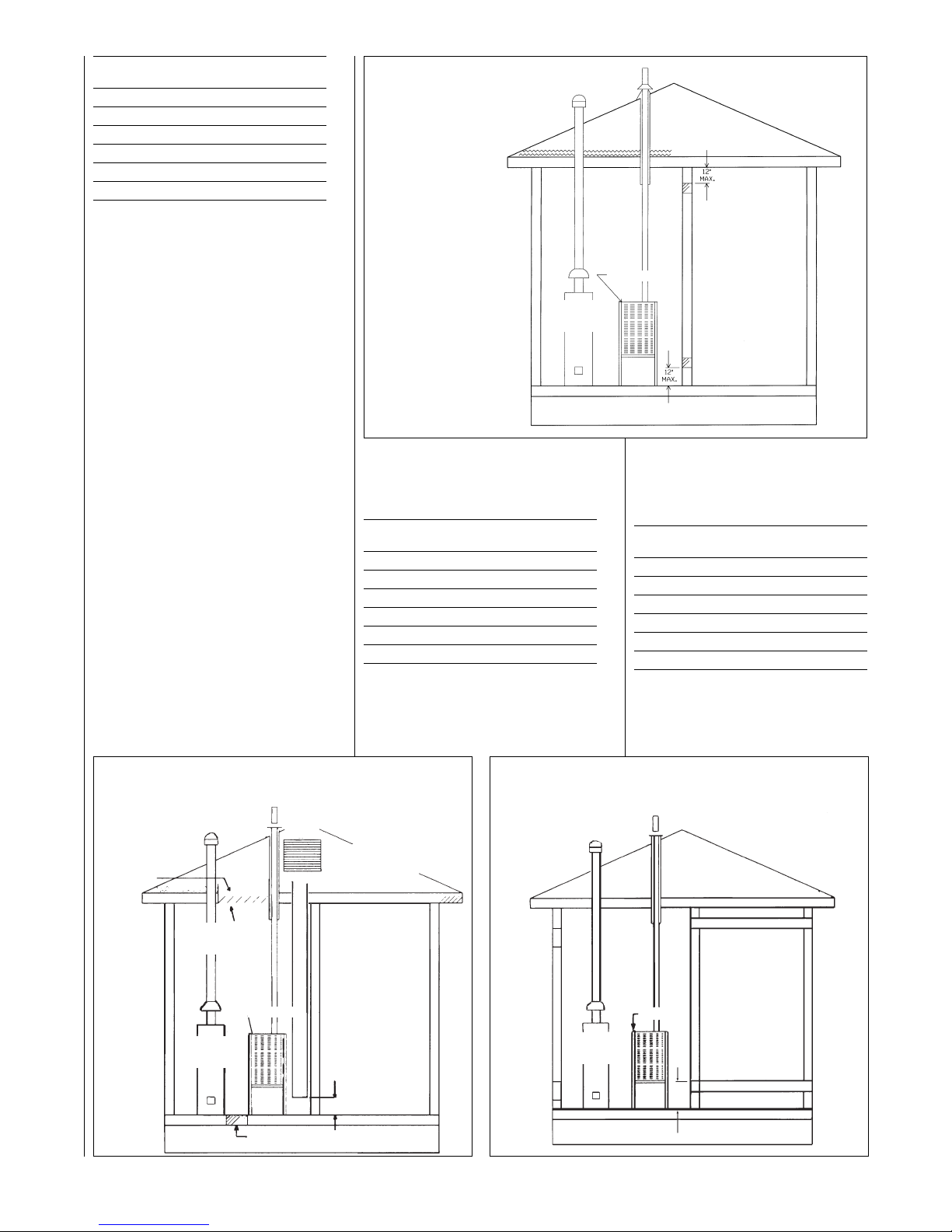
Method 1
Two permanent openings, one
located within 12 inches of the top
and one located within 12 inches
of the bottom of the enclosure,
shall be provided. The openings
shall communicate directly, or by
ducts, with the outdoors or spaces
(crawl or attic) that freely
communicate with the outdoors.
a. Where directly communicating
with the outdoors or where
communicating to the outdoors
through vertical ducts as shown in
Figure 11, each opening shall
have a minimum free area of 1
square inch for each 4,000 BTUH
of total appliance input rating in the
enclosure.
BTUH Free Area Round Pipe
Input Each Opening Size
45,000 11.25 square inches 4"
60,000 15.00 square inches 5"
75,000 18.75 square inches 5"
90,000 22.50 square inches 6"
105,000 26.25 square inches 6"
120,000 30.00 square inches 6"
b. Where communicating with
outdoors through horizontal ducts,
each opening shall have a
minimum free area of 1 square
inch for each 2,000 BTUH of total
input rating of all equipment in the
enclosure.
Here are some typical sizes.
BTUH Free Area Round Pipe
Input Each Opening Size
45,000 22.50 square inches 6"
60,000 30.00 square inches 6"
75,000 37.50 square inches 7"
90,000 45.00 square inches 8"
105,000 52.50 square inches 8"
120,000 60.00 square inches 9"
Method 2
One permanent opening, located
within 12 inches of the top of the
enclosure, shall be permitted
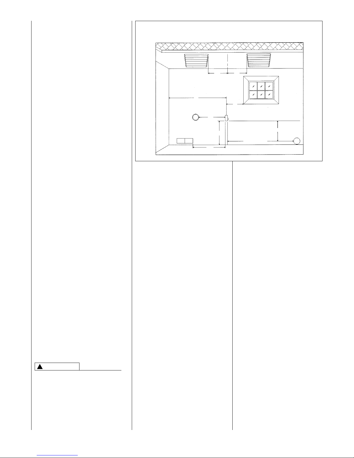
FIGURE 11
AIR FROM ATTIC/CRAWL SPACE
FIGURE 12
OUTSIDE AIR USING A HORIZONTAL DUCT
FIGURE 10
AIR FROM HEATED SPACE
NOTE:
EACH OPENING SHALL
HAVE A FREE AREA OF
NOT LESS THAN ONE
SQUARE INCH PER
1,000 BTU PER H0UR OF
THE
TOTAL
INPUT
RATING OF ALL
EQUIPMENT IN THE
ENCLOSURE, BUT NOT
LESS THAN 100
SQUARE INCHES.
GAS
WATER
HEATER
FURNACE
GAS
WATER
HEATER
GAS
WATER
HEATER
FURNACE
FURNACE
12" MAX.
12"
MAX.
1 SQ. INCH PER
4000 BTUH INLET AIR
OUTLET AIR 1 SQ. INCH
PER 2000 BTUH
INLET AIR 1 SQ. INCH
PER 2000 BTUH
1 SQ. INCH PER
4000 BTUH
OUTLET AIR
OUTLET AIR
IN ATTIC
MUST BE
ABOVE
INSULATION
OPTIONAL 1 SQ. INCH PER 4000 BTUH INLET AIR
VENTILATED
ATTIC GABLE OR
SOFFIT VENTS
GABLE
VENT
Page 16
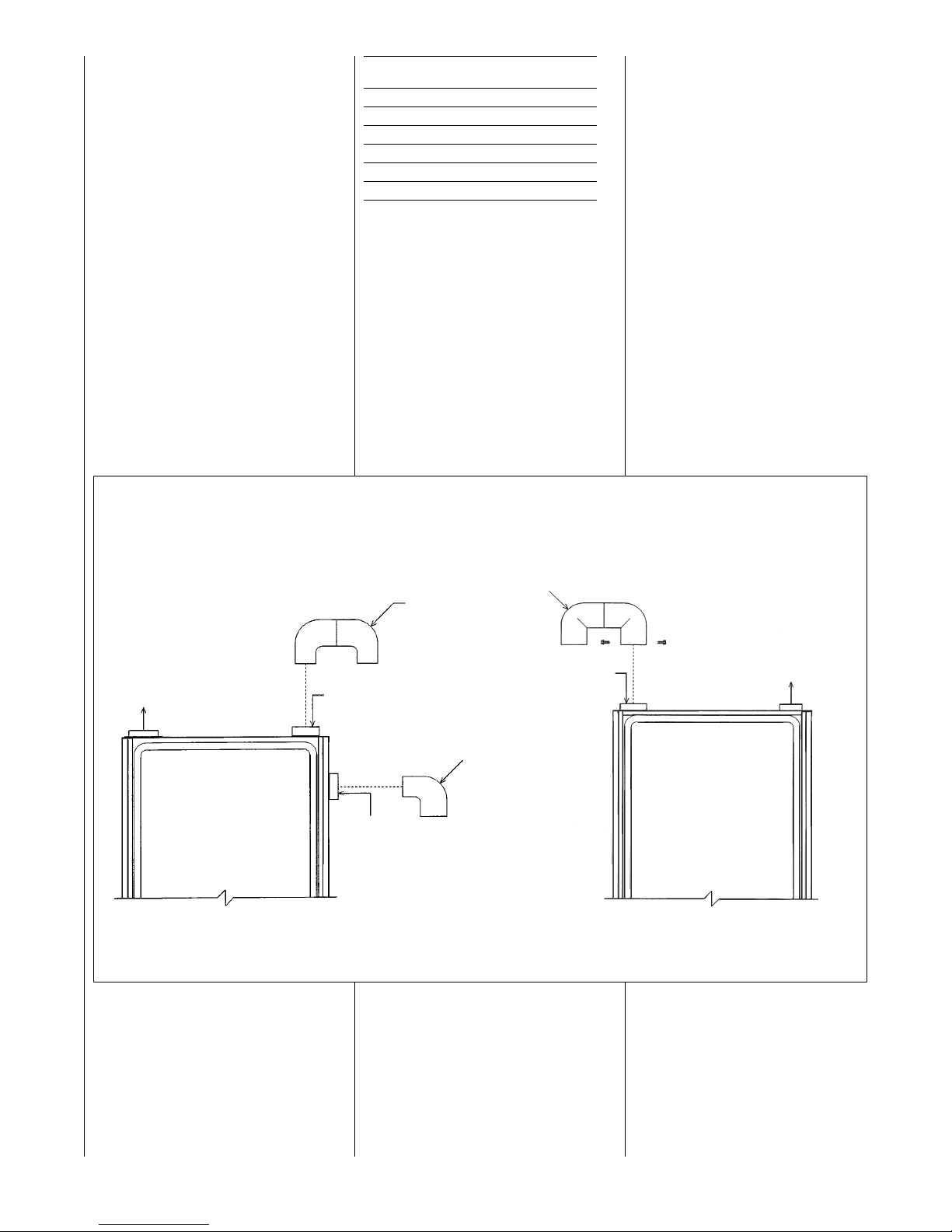
FIGURE 13
COMBUSTION AIR FITTING
UPFLOW DOWNFLOW/HORIZONTAL
2" PVC
DOUBLE
ELBOW
TOP
OPTION
EXHAUST
2" PVC ELBOW
SIDE
OPTION
2" PVC
DOUBLE
ELBOW*
COMBUSTION AIR
EXHAUST
ATTACH DOUBLE ELBOW TO INTAKE AIR
COLLAR AND SECURE WITH TWO SHEET
METAL SCREWS TO PREVENT ACCIDENTAL
BLOCKAGE OF INTAKE AIR OPENING.
➤ *NOTE: WHEN FURNACE IS INSTALLED IN
A HORIZONTAL POSITION ONLY ONE 90°
ELBOW IS REQUIRED. INSTALL THE ELBOW
SO THE OPEN END IS POINTED DOWNWARD.
ATTACH DOUBLE ELBOW TO TOP INLET
AIR OPENING OR 90° ELBOW TO SIDE
INLET AIR OPENING TO PREVENT
ACCIDENTAL BLOCKAGE OF INTAKE
OPENING. PLUG OPENING NOT USED.
16
I337 I336
where the equipment has
clearances of at least 1 inch from
the sides and back and 6 inches
from the front of the appliance.
The opening shall directly
communicate with the outdoors or
communicate through a vertical or
horizontal duct to the outdoors or
spaces (crawl or attic) that freely
communicate with the outdoors,
and shall have a minimum free
area of:
a. 1 square inch for each 3,000
BTUH of the total input rating of all
equipment located in the enclosure
and
BTUH Free Area Round Pipe
Input Each Opening Size
45,000 15.00 square inches 4"
60,000 16.67 square inches 5"
75,000 25.00 square inches 6"
90,000 30.00 square inches 6"
105,000 35.00 square inches 7"
120,000 40.00 square inches 7"
b. Not less than the sum of the
areas of all vent connectors in the
confined space.
If unit is installed where there is an
exhaust fan, sufficient ventilation
must be provided to prevent the
exhaust fan from creating a negative
pressure.
Combustion air openings must not be
restricted in any manner.
CONSULT LOCAL CODES FOR
SPECIAL REQUIREMENTS.
Return air grilles and warm air
registers must not be obstructed.
CONNECTION TO
FURNACE
IMPORTANT: When indoor
combustion air is used, the inlet air
opening at the furnace must be
protected from accidental blockage.
On upflow models, install a 90° elbow
pointing downward in the side inlet air
opening or a double elbow pointing
downward in the top inlet air opening.
On downflow/horizontal models,
install a double elbow in the top inlet
air opening. See Figure 13.
Page 17
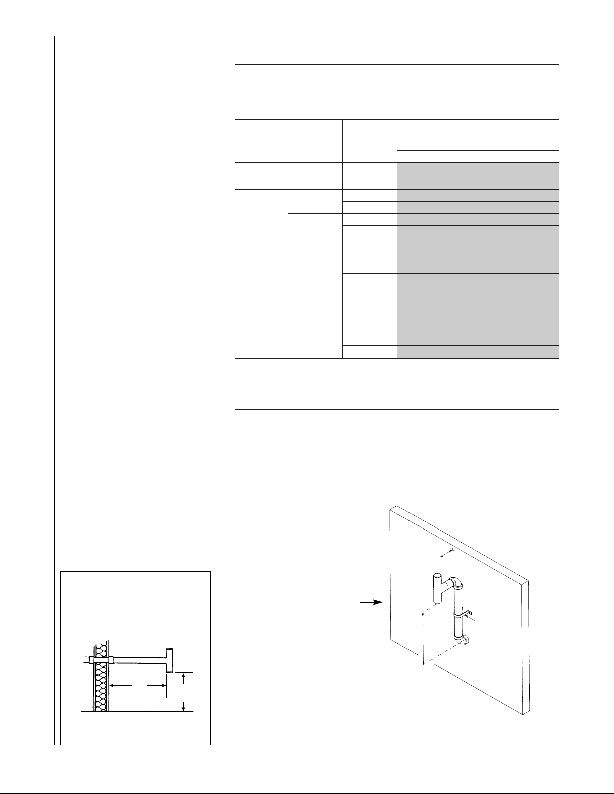
ELEVATED SINGLE PIPE ALTERNATE TEE TERMINATION
See Figure 15. The tee termination may be elevated up to 24 inches above the
wall penetration if required for anticipated snow levels. Use 2 medium-radius, 2-in.
PVC elbows and 2-in. PVC pipe, attaching the tee so it is 12 inches from the wall.
17
NON-DIRECT VENT
INSTALLATION
GUIDELINES
IMPORTANT: FAILURE TO
CORRECTLY FOLLOW ALL
VENTING GUIDELINES MAY
RESULT IN ERRATIC FURNACE
OPERATION, FREEZE-UP OF
COMBUSTION AIR OR EXHAUST
AIR PIPING OR SOOTING OF THE
FURNACE.
All exhaust piping must be installed in
compliance with Part 7, “Venting of
Equipment,” of the latest edition of the
National Fuel Gas Code NPFA54/
ANSI Z223.1-, CAN/CGA-B149, local
codes or ordinances and these
instructions.
1. Vertical piping is preferred.
2. All horizontal piping must slope
upward a minimum of
1
/4 inch
per foot of run so that
condensate drains toward the
furnace.
3. All horizontal runs must be
supported at least every 4 feet.
No sags or dips are permitted.
4.
IMPORTANT: DO NOT
COMMON VENT WITH ANY
OTHER APPLIANCE. DO NOT
INSTALL IN THE SAME CHASE
OR CHIMNEY WITH A METAL
OR HIGH TEMPERATURE
PLASTIC PIPE FROM
ANOTHER GAS OR FUELBURNING APPLIANCE
UNLESS THE REQUIRED
MINIMUM CLEARANCES TO
COMBUSTIBLES ARE
MAINTAINED BETWEEN THE
PVC PIPE AND OTHER PIPES.
5. All vent runs through unconditioned spaces where belowfreezing temperatures are
expected should be insulated
with 1-in. thick, medium-density,
foil-faced fiberglass. An
equivalent “arm-a-flex” or
FIGURE 14
TEE TERMINAL – FOR
STANDARD HORIZONTAL
SINGLE PIPE INSTALLATION
FIGURE 15
ALTERNATE HORIZONTAL
TERMINATION FOR
NON-DIRECT VENT
INSTALLATIONS
12"
FROM
24"
MAX.
PIPE
SUPPORT
STRAP
OUTSIDE
WALL
VENT
12"
12" MIN. ABOVE
GRADE OR
SNOW LEVEL
I198
NUMBERS OF ELBOWS
45° OR 90°
Medium / Long Radius ONLY
1-2 3-4 5-6
45,000 2”
Standard 60 55 50
Alternate 55 50 45
2”
Standard 35 30 25
Alternate 30 25 20
60,000
3”
Standard 120 120 115
Alternate 120 120 110
2”
Standard 20 15 10
Alternate NR NR NR
75,000
3”
Standard 110 105 95
Alternate 80 70 65
90,000 3”
Standard 90 85 75
Alternate 60 50 45
105,000 3”
Standard 80 75 65
Alternate 50 40 35
120,000 3”
Standard 70 65 55
Alternate 40 30 25
NOTES:
1. *N.R. - NOT RECOMMENDED.
2. MAXIMUM OF 6 - 90 DEGREE ELBOWS MAY BE USED. DO NOT COUNT ELBOWS REQUIRED FOR
ALTERNATE TERMINATION. USE ONLY MEDIUM OR LONG SWEEP ELBOWS.
3.
➤ A 45° DEGREE ELBOW IS CONSIDERED ONE ELBOW.
FURNACE
INPUT
➤TABLE 1
FOR NON-DIRECT VENT APPLICATIONS - AIR FOR COMBUSTION
PROVIDED FROM INDOORS
MAXIMUM ALLOWABLE LENGTH IN FEET OF EACH EXHAUST PIPE AND INTAKE PIPE
VENT PIPE INSTALLATION
PIPE
SIZE
TERMINATION
Page 18
“rub-a-tex” insulation may also be
used as long as there is no heat
tape applied to the vent pipe. For
horizontal runs where water may
collect, wrap the vent pipe with
self-regulating 3 or 5 watt heat
tape. The heat tape must be
U.L. listed and installed per the
manufacturer’s instructions.
6. The minimum vent pipe length is
5 feet.
STANDARD INSTALLATIONS
The single-pipe system requires an
exhaust pipe only. Combustion air
may be taken from the furnace
installation area or ducted to the
furnace area from the outside.
Size the exhaust pipe as specified in
Table 1. This table lists the maximum
allowable length in feet of the exhaust
pipe that may be used for all furnace
inputs as related to the number of
elbows required and the termination.
(See shaded area.)
Vertical through-the-roof installations
do not require a vent termination. Use
2-in. PVC pipe extending a minimum
of 12 inches above the anticipated
level of snow accumulation. See
exhaust pipe requirements, Figure 20.
When 3-in. vent pipe is used from
furnace to the roof, reduce it to
2 inches before penetrating the roof.
A maximum of 18 inches of 2-in. pipe
may be used below the roof.
Horizontal vent terminations require a
2-in. PVC tee positioned 12 inches
from the outside wall. See exhaust
pipe requirements, Figure 21. When
3-in. pipe is used from the furnace to
the outside wall, reduce it to 2 inches
before penetrating the wall. A
maximum of 18 inches of 2-in. pipe
may be used inside the wall.
An alternate termination may be used
as shown in Figure 15 to clear
anticipated snow levels. The tee may
be raised up to 24 inches above the
wall penetration. Use two mediumradius bend, 2-in. PVC elbows and a
length of 2-in. PVC pipe so that the
elbows are on 24-in. centers.
NON-DIRECT VENT TERMINATION
LOCATION REQUIREMENTS
MOISTURE IN THE COMBUSTION
PRODUCTS CONDENSES AS IT
LEAVES THE TERMINATION. THIS
CONDENSATE CAN FREEZE ON
EXTERIOR WALLS, UNDER THE
EAVES, AND ON SURROUNDING
OBJECTS. SOME DISCOLORATION IS TO BE EXPECTED.
HOWEVER, IMPROPER LOCATION
18
OR INSTALLATION CAN CAUSE
STRUCTURAL OR EXTERIOR
FINISH DAMAGE TO THE
BUILDING.
Non-direct venting location
requirements are slightly different in
some cases than direct venting. Install
a non-direct vent with the following
minimum clearances.
See Figure 16.
1. Locate the bottom of the vent
terminal at least 12 inches above
grade. Increase the 12-in.
minimum to keep the terminal
openings above the level of snow
accumulation, where applicable.
2. The vent shall not terminate over
public walkways or over an area
where condensate or vapor could
create a nuisance or hazard.
3. 4 feet below, 4 feet horizontally
from, or 1 foot above any door,
window soffit, under eave vent or
gravity air inlet to the building.
4. The vent terminal shall have a
minimum horizontal clearance of
4 feet from electric meters, gas
meters, regulators and relief
equipment.
5. 6 feet from an inside corner
formed by two exterior walls –
10 feet is the recommended
distance.
6. Locate it 3 feet above any forced
air inlet located within 10 feet.
Any fresh air or make-up air inlet,
such as for a dryer or furnace
area, is considered a forced air
inlet.
!
CAUTION
FIGURE 16
NON-DIRECT VENT TERMINATION CLEARANCES
I133
SOFFIT
VENTS
FRESH
AIR
INTAKE
*NOTE: FOR DISTANCES OVER 10* NO
VERTICAL RESTRICTIONS APPLY.
INSIDE
CORNER
ELECTRIC
METER
10* RECOMMENDED
12( MIN.
UP TO10**
4*
4*
3*
4*
4*
4*
6*
7. Avoid areas where dripping
condensate may cause problems,
such as above planters, patios, or
adjacent to windows where
steam may cause fogging.
In addition to the minimum clearances
listed above, the vent location should
also be governed by the following
guidelines.
1. Do not terminate under any kind
of patio or deck. If running the
vent under a deck, insulate it to
insure no condensate freezes
and blocks the pipe.
2. Do not locate on the side of a
building with prevailing winter
winds. This will help prevent
moisture from freezing on walls
and overhangs (under eaves).
3. Do not extend vent directly
through brick or masonry
surfaces. Use a rust-resistant
sheet metal or plastic backing
plate behind vent.
4. Do not locate too close to shrubs
as condensate may stunt or kill
them.
5. Minimum vertical clearances of 1
foot are recommended for
overhangs up to 1 foot horizontal.
The vertical clearance should be
increased equally for each
additional increase in horizontal
overhang to a maximum vertical
clearance of 6 feet.
6. Caulk all cracks, seams and
joints within 6 feet horizontally
and above and below vent.
Page 19
19
DIRECT VENT
INSTALLATIONS
READ AND FOLLOW ALL
INSTRUCTIONS IN THIS SECTION.
FAILURE TO PROPERLY VENT
THIS FURNACE CAN CAUSE
CARBON MONOXIDE POISONING
OR AN EXPLOSION OR FIRE,
RESULTING IN PROPERTY
DAMAGE, PERSONAL INJURY
OR DEATH.
Direct vent installations require a
dedicated combustion air and venting
system. All air for combustion is taken
from the outside atmosphere and all
combustion products are discharged
to the outdoors. Therefore, no
ventilation or combustion air
openings are required.
IMPORTANT: The plastic combustion
air and venting components are of
Schedule 40 PVC. If using ABS
piping ensure that the solvent cement
is compatible for joining PVC to ABS
components or use a mechanical
connection that can withstand the
vent temperatures and are corrosion
resistant.
INSTALLATION GUIDELINES
All exhaust piping must be installed in
compliance with Part 7, “Venting of
Equipment,” of the latest edition of the
National Fuel Gas Code NPFA54/
ANSI Z223.1-, CAN/CGA-B149, local
codes or ordinances and these
instructions.
1. Vertical piping is preferred.
2. All horizontal piping must slope
upward a minimum of
1
/4 inch
per foot of run so that condensate
drains toward the furnace.
3. All horizontal runs must be
supported at least every 4 feet.
No sags or dips are permitted.
4.
IMPORTANT: DO NOT COMMON VENT WITH ANY OTHER
APPLIANCE. DO NOT INSTALL
IN THE SAME CHASE OR
CHIMNEY WITH A METAL OR
HIGH TEMPERATURE PLASTIC PIPE FROM ANOTHER
GAS OR FUEL-BURNING
APPLIANCE UNLESS THE
REQUIRED MINIMUM
CLEARANCES TO
COMBUSTIBLES ARE
MAINTAINED BETWEEN THE
PVC PIPE AND OTHER PIPES.
5. All vent runs through unconditioned spaces where belowfreezing temperatures are
expected should be insulated
with 1-in. thick, medium-density,
foil-faced fiberglass. An
equivalent “arm-a-flex” or “rub-atex” insulation may also be used
as long as there is no heat tape
applied to the vent pipe. For
horizontal runs where water may
collect, wrap the vent pipe with
self-regulating 3 or 5 watt heat
tape. The heat tape must be
!
WARNING
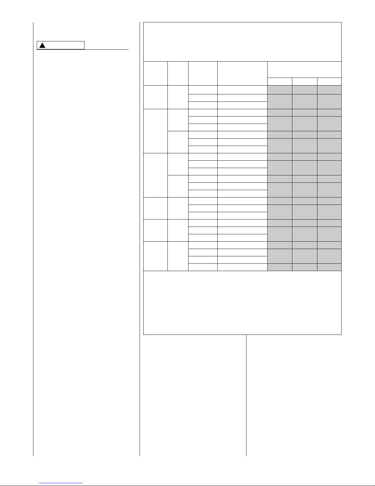
➤TABLE 2
FOR DIRECT VENT APPLICATIONS - AIR FOR COMBUSTION
PROVIDED FROM OUTDOORS
MAXIMUM ALLOWABLE LENGTH IN FEET OF EACH EXHAUST PIPE AND INTAKE AIR PIPE
U.L. listed and installed per the
manufacturer’s instructions.
6. The minimum vent pipe length is
5 feet.
Size the exhaust and combustion air
intake pipes as specified in Table 2.
This table lists the maximum allowable length in feet of the exhaust and
combustion air intake pipes that may
be used for all furnace inputs as
related to the number of elbows
required and the termination (see
shaded area).
FURNACE
INPUT
PIPE
SIZE
TERMINATION
VENT TERMINATION
KIT RECOMMENDED
(RXGY-D0* Kits for
Horizontal Venting Only)
1 - 2 3 - 4 5 - 6
NUMBER OF ELBOWS
45° or 90°
Medium / Long Radius ONLY
Standard RXGY-D02 65 60 55
45,000 2” Concentric RXGY-C01/RXGY-E02
55 50 45
Alternate RXGY-D02
Standard RXGY-D02 40 35 30
2” Concentric RXGY-C01/RXGY-E02
30 25 20
Alternate RXGY-D02
60,000
Standard RXGY-D03 120 120 120
3” Concentric RXGY-C01/RXGY-E02
110 105 100
Alternate RXGY-D03
Standard RXGY-D02 20 15 10
2” Concentric Not Recommended
NR NR NR
Alternate Not Recommended
75,000
Standard RXGY-D03 120 120 120
3” Concentric RXGY-C01/RXGY-E02
100 95 85
Alternate RXGY-D03
Standard RXGY-D03 110 105 95
90,000 3” Concentric RXGY-C01/RXGY-E02
50 40 35
Alternate RXGY-D03
Standard RXGY-D03 110 105 95
105,000 3” Concentric RXGY-C01/RXGY-E02
50 40 35
Alternate RXGY-D03
Standard RXGY-D03 105 100 90
120,000 3”
Concentric RXGY-C01/RXGY-E02
45 35 30
Alternate RXGY-D03
Alternate RXGY-D04 105 95 90
NOTES:
1. N.R. - NOT RECOMMENDED.
2. MAXIMUM OF 6 ELBOWS MAY BE USED. DO NOT COUNT ELBOWS IN ALTERNATE TERMINATION KIT.
MEDIUM OR LONG SWEEP ELBOWS MAY BE USED.
3. ➤ A 45 DEGREE ELBOW IS CONSIDERED ONE ELBOW.
4. CONCENTRIC TERMINATION NO. RXGY-C01 IS FOR THRU-THE-WALL VENTING.
5. CONCENTRIC TERMINATION NO. RXGY-E02 IS FOR THRU-THE-ROOF VENTING.
6. USE KITS RXGY-DO2 (2") OR RXGY-D03 (3") FOR STANDARD OR ALTERNATE THRU-THE-WALL VENTING.
7. USE KITS RXGY-D04 FOR ALTERNATE VENTING OF 120,000 BTUH UNITS WITH LONG RUNS.
Page 20

20
➤ALTERNATE
TERMINATIONS
ALTERNATE HORIZONTAL
DIRECT VENT TERMINATIONS
KIT NOS. RXGY-D02, -D03
AND -D04
The combustion air and exhaust
terminations may be raised a
maximum of 60 inches above the
wall penetration to maintain the
required 12 inch clearance above
grade or snow level. See Figure 17.
Size the pipe length according to
Table 2.
IMPORTANT: The following
guidelines must be met when
extending beyond 24 inches of pipe
on the exterior of the structure:
• Size the entire vent system
according to the concentric, not
standard, termination shown in
Table 2.
COMBUSTION AIR FOR
DIRECT VENT
INSTALLATIONS
THE COMBUSTION AIR SYSTEM
DESIGNED FOR THIS FURNACE
MUST BE USED.
When this furnace is installed as a
direct vent forced air furnace, all
combustion air is supplied directly to
the burner through a special air inlet
system outlined in these instructions.
This system consists of field-supplied
Schedule 40 or 26 SDR-PVC pipe
and one of the following horizontal
vent termination kits: RXGY-D02,
RXGY-D03, RXGY-D04, RXGY-C01
or RXGY-E02.
NOTE: Schedule 40 ABS-DWV pipe
and fittings may be used as an
alternate to PVC pipe for the
combustion air inlet and vent pipes.
The combustion air for this furnace is
supplied directly from the outdoors
through the combustion air inlet
system.
When the furnace is installed in the
same space with other gas
appliances, such as a water heater,
be sure there is an adequate supply
of combustion and ventilation air for
the other appliances. Do not delete or
reduce the combustion air supply
required by the other gas appliances
in this space. See Z223.1, National
Fuel Gas Code (NFPA54) or
CAN/CGA-B149.1 and .2 for determining the combustion air requirements for gas appliances. An
unconfined space must have at least
50 cubic feet (volume) for each
1,000 BTUH of the total input of all
appliances in the space. If the open
space containing the appliances is in
a building with tight construction
(contemporary construction), outside
air may still be required for the
appliances to burn and vent properly.
Outside air openings should be sized
the same as for a confined space.
STANDARD TERMINATIONS
STANDARD VERTICAL
TERMINATIONS
COMBUSTION AIR PIPING
Use two medium-radius sweep
elbows to keep the inlet downward to
prevent entry of rain. See Figure 20
for the proper relationship of
combustion air to exhaust
termination.
STANDARD HORIZONTAL
TERMINATIONS
COMBUSTION AIR PIPING
When 3-in. pipe is used between the
furnace and outside wall, reduce it
to 2 inches before penetrating the
wall. Up to 18 inches of 2-in. pipe
may be used inside the wall.
The standard horizontal intake air
termination for all models is a 2-in.
PVC coupling with a wind deflector
vane (provided) attached. Cut a
2
1
/4-in. length of 2-in. PVC pipe.
Connect this pipe and another 2-in.
PVC coupling to the coupling at the
wall. The outer coupling must
terminate 4 inches from the wall. See
Figure 21, Detail B, for vane location.
Attach vane in vertical position with
PVC solvent.
IMPORTANT: To ensure proper
furnace operation, the supplied
vane must be installed in the
vertical position as shown in Figure
21, Detail B.
The combustion air inlet terminal
must be located with respect to the
exhaust terminal as shown in Figure
21, Detail C.
➤ IMPORTANT: All furnaces with
horizontal air intakes, except those
using horizontal concentric vent kit
RXGY-C01, must have a drain tee
assembly and trap installed as
close to the furnace as possible.
This is to drain any water that may
be in the combustion air pipe to
prevent it from entering the
furnace combustion chamber.
These parts are included in kits
RXGY-D02 (for 2-in. pipe), RXGYD03 (for 3-in. pipe) and RXGY-D04
(special for the 120,000 BTU
furnace installed with the alternate
horizontal termination). Attach the
trap to the bottom of the tee with
PVC solvent. Connect the other
end to a suitable drain, as to the
downstream of a condensate trap
on the furnace.
STANDARD VERTICAL
TERMINATIONS
EXHAUST VENT PIPING
Vertical through-the-roof vent appli-
cations do not require an exhaust
terminal. The exhaust vent must
terminate at least 12 inches above
the combustion intake air termination.
The exhaust vent for models with
inputs of 90,000 through 120,000
BTUH is 2-in. PVC pipe 120,000
BTUH models with excessively long
runs require 2
1
⁄2(. Refer to Table 2 for
proper application. This must
be reduced to 1( or 1
1
⁄2( the last
12 inches for models with inputs of
45,000 through 75,000 BTUH.
See Figure 22.
STANDARD HORIZONTAL
TERMINATIONS
EXHAUST PIPING
For direct vent systems the standard
termination is 2-in. PVC pipe
extending 12 inches from the wall for
furnaces with inputs from 90,000 to
120,000 BTUH. Install a 2-in. coupling
at the outside wall to prevent the
termination from being pushed
inward. When 3-in. pipe is used
between the furnace and outside wall,
reduce to 2 inches before penetrating
the wall. The standard termination is
1
1
/2 -in. PVC pipe extending outward
12 inches from the wall for models
with inputs of 45,000 to 75,000
BTUH. Install a 2-in. to 1
1
/2-in.
coupling at the outside wall to prevent
pushing the termination back into the
wall. See Figure 21, Detail B.
The combustion air and exhaust
terminations must be at least 12
inches above grade and must be
oriented with respect to each other as
shown in Figure 21. Refer to section
on alternate venting options when
higher snow levels are anticipated.
Page 21

21
FIGURE 17
ALTERNATE HORIZONTAL DIRECT VENT TERMINATION
SEE DETAIL A
60( MAX.
PIPE
SUPPORT
STRAP
3( MAX.
NOTE: 3-1/2(
MAX. WHEN
D04 KIT IS
USED.
EXHAUST VENT FOR
MODELS WITH
INPUT OF 45,000 THRU
75,000 BTU
DETAIL A
EXHAUST VENT
21/2" PVC FOR MODELS WITH 120,000 BTU INPUT
(KIT NO. RXGY-D04)
2" PVC FOR MODELS WITH INPUTS OF 90,000 THRU 120,000
BTU. REDUCE TO 11/2" FOR MODELS WITH INPUTS OF 45,000
THRU 75,000 BTU. ELBOWS AND RISERS ARE 2" PVC.
INTAKE VENT
21/2" PVC FOR MODELS WITH
120,000 BTU INPUT.
2" PVC ELBOWS AND RISER
MODELS WITH INPUTS OF 45,000
THRU 105,000 BTU.
USE KIT NO. RXGY-D02 WHEN 2" PIPE
IS USED BETWEEN FURNACE AND
OUTSIDE WALL. USE KIT NO. RXGY-D03
WHEN 3" PIPE IS USED.
FIGURE 18
VERTICAL CONCENTRIC VENT KIT - RXGY - E02
12" FIXED
48" MAX.
INLET AIR
12" ABOVE
AVERAGE SNOW
ACCUMULATION
INSTALL ROOF
FLASHING
ROOF LINE
INLET AIR PIPE
2"
USE 2" x 3" INCREASER
IF VENT IS 3" PIPE
(FIELD SUPPLIED)
VENT FROM
FURNACE
INLET AIR FROM
FURNACE, USE
3" x 2" BUSHING
IF INLET IS 2" PIPE
(FIELD SUPPLIED)
➀
➁
➂
➄
➃
➅
➆
➀
➁
➂
➃
➄
➅
➆
2" SCH40 PVC PIPE
3" TYPE SDR 26 PVC PIPE
2" x 3" BUSHING (MODIFIED)
3" x 3" x 3" WYE
2" x 4" COUPLING (MODIFIED)
3" x 45° STREET ELBOW
2" COUPLING
(FIELD SUPPLIED)
• Insulate the entire length of vent
pipe, between the elbow where the
pipe exits the wall and the elbow
where the termination is made, with
a closed-cell insulation, such as
“Arm-a-Flex” or “Rub-a-Tex” with a
minimum of 1/2( thickness.
• All elbows installed on the exterior
of the building must be of the long
sweep nature.
• As required for the horizontal piping
ran within the structure, any pipe
ran horizontal outside the structure
must slope upward a minimum of
1/4( per foot run so that condensate
drains toward the furnace.
From the top elbow in the exhaust
pipe, extend a length of PVC pipe
outward so that it terminates exactly
12 inches from the wall. See Figure
17. Reduce the termination pipe
extension to is 1
1
/2 inch pipe for
45,000 BTUH through 75,000 BTUH
units.
The 45,000 BTUH unit only uses kit
RXGY-D02. The 60,000 BTUH and
75,000 BTUH units may use kits
RXGY-D02 or RXGY-D03 depending
on pipe lengths and number of
elbows. Use kit RXGY-D03 with
90,000 BTUH through 120,000 BTUH
units. The RXGY-D04 kit only
applies to the 120,000 BTUH unit
using an alternate termination and
excessively long runs. See Table 2.
The following are parts lists for the
RXGY-D02, RXGY-D03 and RXGYD04 alternate horizontal direct vent
termination kits:
RXGY-D02
1. 2-in. tee with reducer assembly
2.
1
/2-in. PVC 6-in. dia. trap
3. PVC vane
4. 2-in. PVC elbow
5. 1
1
/2-in. PVC nipple with coupling
6. PVC strap
7. vent template
RXGY-D03
1. 3-in. tee with reducer assembly
2.
1
/2-in. PVC 6-in. dia. trap
3. PVC vane
4. 2-in. PVC elbow
5. PVC strap
6. vent template
I339
I338
12( FROM WALL
Page 22

22
HORIZONTAL CONCENTRIC
TERMINATION
This kit is for horizontal intake air pipe
runs and may be installed through
walls up to 16 inches thick. See
Figure 19. Complete installation
instructions are supplied with the kits.
FIGURE 19
HORIZONTAL CONCENTRIC VENT KIT NO. RXGY-C01
(DIRECT VENT INSTALLATIONS)
RXGY-D04
1. 2
1
/2-in. PVC elbow
2. 3" x 2
1
/2" PVC bushing
3. 2
1
/2" x 61/2" long PVC pipe
4. 2
1
/2" x 16" long PVC pipe
5. 2
1
/2" x 21" long PVC pipe
6. PVC vane
7. ➤
3-in. tee with reducer assembly
8. 6-in. dia. 1/2-in. PVC trap
9. PVC strap
10. vent template
NOTE: The RXGY-D04 kit only
applies to the 120,000 BTUH unit
using an alternate termination and
excessively long runs.
CONCENTRIC
TERMINATIONS
ALTERNATE VERTICAL
CONCENTRIC VENT
KIT NO. RXGY-E02
This kit is for vertical intake air/vent
runs and may be installed through
roofs up to 9 inches thick. One
4
1
/8-in. diameter hole is required
through the roof for the installation.
See Figure 18 for the general layout.
Complete installation instructions are
included with the kit.
Page 23

23
FIGURE 20
STANDARD VERTICAL DIRECT VENTING
UPFLOW MODEL SHOWN (TYPICAL FOR DOWNFLOW MODELS)
FIGURE 21
STANDARD HORIZONTAL DIRECT VENTING
UPFLOW MODEL SHOWN (TYPICAL FOR DOWNFLOW MODELS)
I407
EXHAUST
TERMINATION
➀
➁
3" MAX.
SEPARATION
COMBUSTION AIR
PIPE
12" MIN.
SEPARATION
12" MIN. ABOVE
ROOF LEVEL
ROOF LINE
EXHAUST PIPE
COMBUSTION
AIR PIPE
SUPPLY AIR
RETURN AIR
EXHAUST VENT
➂
➃
3"
MAX.
EXHAUST
VENT
ROOF LINE
COMBUSTION
AIR PIPE
12"
MIN.
12" MIN.
ANTICIPATED
SNOW LEVEL
COMBUSTION
AIR PIPE
3"
MAX.
EXHAUST
VENT
12"
MIN.
12" MIN.
3"
MAX.
12" MIN.
12" MIN. ABOVE
ANTICIPATED SNOW LEVEL
➄
NOTES:
➀
THE COMBUSTION AIR PIPE
MUST TERMINATE IN THE
SAME PRESSURE ZONE AS
THE EXHAUST PIPE.
➁
INCREASE THE 12-IN. MINIMUM
TO KEEP TERMINAL OPENING ABOVE
ANTICIPATED LEVEL OF SNOW
ACCUMULATION WHERE
APPLICABLE.
➂
WHEN 3-IN. DIAM. PIPE IS USED,
REDUCE TO 2-IN. DIAMETER BEFORE
PENETRATING ROOF. A MAXIMUM OF
18 IN. OF 2-IN. PIPE MAY BE USED
BEFORE PASSING THROUGH ROOF.
➃
SUPPORT VERTICAL PIPE EVERY 6
FEET.
➄
EXHAUST TERMINATION - TERMINATE
THE LAST 12 INCHES WITH 2( PVC
PIPE ON 90,000 THROUGH 120,000
BTUH MODELS. REDUCE AND
TERMINATE THE LAST 12 INCHES
WITH 1
1
⁄2( PVC PIPE ON 45,000
THROUGH 75,000 BTUH MODELS.
PITCHED ROOF INSTALLATIONS
NOTES:
➀
SUPPORT HORIZONTAL PIPE
EVERY FOUR FEET.
➁
WHEN 3 IN. PIPE IS USED REDUCE TO 2 IN.
BEFORE PENETRATING OUTSIDE WALL.
➂
18 IN. MAXIMUM. 2 IN. DIAMETER PIPE MAY
BE USED INSIDE THE WALL.
➃
DETAIL “A” - EXHAUST TERMINATION
TERMINATE THE LAST 12 INCHES WITH 2(
PVC PIPE ON 90,000 THROUGH 120,000
BTUH MODELS. REDUCE AND TERMINATE
THE LAST 12 INCHES WITH 1
1
⁄2( PVC PIPE
ON 45,000 THROUGH 75,000 BTUH MODELS.
➄
INCREASE THE 12 IN. MINIMUM ABOVE
GRADE TO KEEP TERMINAL OPENINGS
ABOVE ANTICIPATED LEVEL OF SNOW
ACCUMULATION WHERE APPLICABLE.
➅
DETAIL “B”, INSTALL WIND DEFLECTOR
VANE IN 2 IN. PVC COUPLING IN VERTICLE
POSITION USING PVC SOLVENT.
THE COMBUSTION AIR TERMINATION MUST
BE IN THE SAME PRESSURE ZONE AS THE
EXHAUST TERMINATION.
3(
12(
4(
4(
SEE DETAIL A
VANE
2( PVC
COUPLING
12( MIN. ABOVE
GRADE LEVEL
➄
SEE DETAIL B
2( OR 3( TEE
W/DRAIN TRAP
RETURN AIR
TRAP
SUPPLY AIR
EXHAUST PIPE
COMBUSTION AIR PIPE
CONNECT
TO DRAIN
12(
4(
EXHAUST
INTAKE
OPTIONAL
INTAKE
DETAIL C
EXHAUST / INTAKE RELATIONSHIP
EXHAUST TERMINATION
➃DETAIL A
COMBUSTION AIR TERMINATION
➅DETAIL B
➀➁
➂
I407
Page 24

24
LOCATION REQUIREMENTS
HORIZONTAL DIRECT VENTS
THE COMBUSTION PRODUCTS
AND MOISTURE IN THE FLUE
GASES WILL CONDENSE AS THEY
LEAVE THE TERMINATION. THE
CONDENSATE CAN FREEZE ON
THE EXTERIOR WALL, UNDER
THE EAVES AND ON SURROUNDING OBJECTS. SOME DISCOLORATION TO THE EXTERIOR OF THE
BUILDING IS TO BE EXPECTED.
HOWEVER, IMPROPER LOCATION
OR INSTALLATION CAN RESULT
IN STRUCTURAL OR EXTERIOR
FINISH DAMAGE TO THE BUILDING AND MAY RECIRCULATE
PRODUCTS OF COMBUSTION
INTO THE COMBUSTION AIR
TERMINAL AND FREEZE.
NOTE: In Canada vent terminations
should be done in accordance with
the current CAN/CGA-B149 Gas
Installation Code and/or local codes.
The vent must be installed with the
following minimum clearances. See
Figures 22 and 23.
1. The bottom of the vent terminal
and the air inlet shall be located
at least 12 inches above grade.
Increase the 12-in. minimum to
keep the terminal openings
above the level of snow
accumulation, where applicable.
2. The vent shall not terminate over
public walkways or over an area
where condensate or vapor could
create a nuisance or hazard.
3. The vent terminal shall be
located at least one foot from any
opening through which flue
gases could enter a building.
4. The vent terminal shall be at
least 3 feet above any forced air
inlet located within 10 feet,
except the combustion air inlet of
a direct vent appliance.
5. The vent terminal shall have a
minimum horizontal clearance of
4 feet from electric meters, gas
meters, regulators and relief
equipment.
6. The air inlet shall be located at
least 10 feet horizontally from the
vent of any other gas or fuel
burning appliance or electric
clothes drier. The only exception
to this requirement is the case of
multiventing two or more of these
furnaces. For those specifics
refer to the section on
multiventing in these instructions.
In addition to the minimum clearances
listed above, the vent location should
also be governed by the following
guidelines.
1. Do not terminate under any
kind of patio or deck. If running
the vent under a deck, insulate
it to insure no condensate
freezes and blocks the pipe.
2. Do not terminate behind any area
that may allow the flue products
to become stagnant and
recirculate.
3. Do not locate on the side of a
building with prevailing winter
winds. This will help prevent
moisture from freezing on walls
and overhangs (under eaves).
4. Do not extend vent directly
through brick or masonry
surfaces. Use a rust-resistant
sheet metal or plastic backing
plate behind vent. See Figure 19.
5. Do not locate too close to shrubs
as condensate may stunt or
kill them.
6. Minimum vertical clearances of 1
foot are recommended for
overhangs up to 1 foot horizontal.
The vertical clearance should be
increased equally for each
additional increase in horizontal
overhang to a maximum vertical
clearance of 6 feet.
7. Caulk all cracks, seams and
joints within 6 feet horizontally
and above and below vent.
See Figure 23.
FIGURE 22
MOISTURE ZONES
FIGURE 23
DIRECT VENT MINIMUM CLEARANCES
!
CAUTION
Page 25

25
FIGURE 24
TWO FURNACE VENTING THROUGH ROOF
FIGURE 25
TWO FURNACE VENTING THROUGH WALL
8. Painted surfaces must be sound
and in good condition with no
cracking, peeling, etc. Painted
surfaces will require
maintenance.
9. Do not expose 3" x 2" reducer/
bushing to outdoor ambient
temperatures.
MULTIVENTING
IF VENTING TWO OR MORE
FURNACES NEAR EACH OTHER IS
REQUIRED, EACH FURNACE
MUST BE INDIVIDUALLY VENTED
– NO COMMON VENTING IS
PERMITTED. See Figures 24 and 25
for positioning of the terminations.
When more than two furnaces are to
be vented, there must be at least 4
feet between the first two furnaces
and the third, etc.
Page 26

26
CONNECTING TO FURNACE
IMPORTANT: Clean and debur all
pipe cuts. The shavings must not be
allowed to block the exhaust, inlet or
condensate drain pipes.
UPFLOW FURNACE
The exhaust pipe connection is a 2-in.
female PVC pipe fitting extending
through the left side of the furnace top
plate. This opening has a protective
cap which should be removed just
prior to installing the exhaust pipe.
When 2-in. pipe is used, connect it
directly to this fitting. When 3-in. pipe
is used, connect a 2 to 3-in. coupling
to this fitting with a short piece of 2-in.
PVC pipe.
The inlet combustion air connection
is at the right side of the top plate.
An alternate combustion inlet air
connection may be made on the right
side of the jacket. This opening has a
plastic cap. A combustion inlet air
connection fitting is supplied with the
furnace and it must be installed in the
furnace by screwing it into the
opening. Make sure the rubber
“O-ring” supplied with the furnace is
used with this fitting. See Figure 26.
DOWNFLOW/HORIZONTAL
FURNACE
The exhaust pipe connection is a 2-in.
upflow only PVC pipe fitting extending
through the right side of the furnace
top cover. This opening has a protective cap which should be removed
just prior to installing the exhaust
pipe. When 2-in. pipe is used, connect it directly to this fitting. When
3-in. pipe is used, connect with a
2- to 3-in. coupling directly to the
2-in. pipe.
The combustion inlet air connection is
a 2-in. extruded hole on the left side
of the top plate. When a 2-in. pipe is
used, attach a 2-in. PVC coupling
over this hole with RTV sealant and
also add two sheet metal screws
through the coupling into the
extrusion to secure it in place, and
add the required piping. When 3-in.
pipe is required, use a 2- to 3-in.
coupling and add the required piping.
See Figure 27.
FIGURE 26
UPFLOW COMBUSTION AIR AND VENT PIPE CONNECTION
FIGURE 27
DOWNFLOW/HORIZONTAL COMBUSTION AIR AND VENT PIPE
CONNECTION
VENT CAP/PLUG
VENT CAP/PLUG
OUTLET AIR PIPE
PIPE - PVC
CONNECTOR
CONNECTOR
EXHAUST
TRANSITION
EXHAUST
TRANSITION
PLUG OPT.
COMBUSTION
AIR INLET
POSITION
COMBUSTION AIR
ADAPTER
TOP PLATE
TOP PLATE
“O” RING
COUPLING
NOTE: ATTACH COUPLING
TO EXTRUDED COLLAR
WITH TWO SCREWS. PUT
BEAD OF SILICONE AROUND
BASE BEFORE MOUNTING
COUPLING.
COMBUSTION
AIR CHASE
INDUCED DRAFT
BLOWER
INDUCED DRAFT
BLOWER
CONDENSATE TRAP
NOTE:
WHEN COMBUSTION AIR INLET IS IN
OPTIONAL POSITION, SWAP LOCATION
OF INLET AIR ADAPTER AND “O” RING
WITH PLUG.
PVC
PVC
OUTLET AIR
PIPE
I329
I329
Page 27

FIGURE 29
DOWNFLOW CONDENSATE DRAIN
CONDENSATE DRAIN/NEUTRALIZER
27
FIGURE 28
UPFLOW CONDENSATE DRAIN
GENERAL INFORMATION
DO NOT RUN DRAIN OUTDOORS.
FREEZING OF CONDENSATE CAN
CAUSE PROPERTY DAMAGE.
IMPORTANT: Do not connect into a
common drain line with an air conditioner evaporator coil drain located
below the furnace. A blocked or
restricted drain line can result in overflow of the coil pan and negate the
furnace blocked drain shutoff control.
FILL TRAP ASSEMBLY WITH
WATER BEFORE OPERATING THE
FURNACE. This can be done by
removing the drain hose
from the trap and pouring about a
cup of water into the vent trap. Water
will flow into the house drain when the
trap is full.
If local codes require, install a
condensate neutralizer cartridge in
the drain line. Install cartridge in
horizontal position only. Also install
an overflow line if routing to a floor
drain. See Figures 28 and 29.
If no floor drain is available, install a
condensate pump that is resistant to
acidic water. Pumps are available
from your local distributor. If pump
used is not resistant to acidic water, a
condensate neutralizer must be used
ahead of the pump. The condensate
pump must have an auxiliary safety
switch to prevent operation of the
furnace and resulting overflow of
condensate in the event of pump
failure. The safety switch must be
wired through the “R” circuit only (low
voltage) to provide operation in either
heating or cooling modes.
UPFLOW MODELS
The condensate drain trap is located
in the blower compartment on the lefthand side of the jacket. A short piece
of
1
/2-in. PVC pipe and a 1/2-in. tee are
provided. Connect the 1/2-in. pipe to
the elbow on the trap and the tee to
this pipe so that the open end is
upward. Connect at least a 5( riser to
the top of the tee and run a drain tube
from the bottom of the tee to a floor
drain or condensate pump.
IMPORTANT: If installing the unit
over a finished ceiling or living area,
be certain to install an auxiliary
condensate drain pan under the
entire unit extending out under the
condensate tee. With a 5 inch riser
installed above the tee, a blocked
drain will result in overflow from the
riser.
To cause the furnace to shut down
when a blocked drain is present,
install a riser which is a minimum of
10
13
⁄16(. If the furnace is installed in an
attic, crawlspace or other area where
freezing temperatures may occur, the
furnace drain can freeze while shut
off for long periods of time.
Use a solvent cement that is
compatible with PVC material. Cut the
drain hoses to the appropriate length
and connect to the trap with hose
clamps. Tighten the clamps with
pliers and check for leaks after
attaching.
DOWNFLOW MODELS
The condensate trap is located on the
right side of the cabinet in the burner
compartment. A short piece of
1
/2-in.
PVC pipe and a 1/2-in. tee are
provided. Connect the 1/2-in. pipe to
the elbow on the trap and the tee to
this pipe so that the open end is
upward. Connect a 51⁄2-in. riser to the
top of the tee and run a drain tube
from the bottom of the tee to a floor
drain or condensate pump. Use a
solvent cement that is compatible with
PVC material.
!
CAUTION
NEUTRALIZER CARTRIDGE
(OPTIONAL)
TO FLOOR DRAIN OR CONDENSATE PUMP
NOTE:
DRAIN VENT NEEDS
TO BE ABOVE
COLLECTOR BOX
DRAIN SPOUT.
MINIMUM HEIGHT
OPEN TOP
CONDENSATE TRAP
DRAIN LINE
I408
OVERFLOW LINE
(REQUIRED ONLY WHEN
OPTIONAL NEUTRALIZER
CARTRIDGE IS USED.)
I408
MINIMUM HEIGHT
OPEN TOP
DRAIN LINE CONDENSATE TRAP
TO FLOOR DRAIN OR CONDENSATE PUMP
NEUTRALIZER CARTRIDGE
(OPTIONAL)
OVERFLOW LINE
(REQUIRED ONLY WHEN
OPTIONAL NEUTRALIZER
CARTRIDGE IS USED.)
5(
Page 28

28
➤ FIGURE 30
UPFLOW OPPOSITE SIDE CONDENSATE TRAP CONNECTION
FIGURE 31
DOWNFLOW OPPOSITE SIDE CONDENSATE TRAP CONNECTION
REVERSING THE TRAP
UPFLOW UNITS
The trap may be moved to the right
side for right side drainage. Open the
knockout for the drain on the right
side of the cabinet. Remove the
bracket holding the trap from the left
side. Seal the left side drain hole with
a plug provided in the cloth bag with
the furnace. Position the mounting
bracket and trap so that the drain
elbow is centered in the hole on
the right. See Figure 30.
Drill two holes in the cabinet to mount
the bracket. Mount the trap and
bracket to the right side with the drain
elbow pointing through the knockout.
Connect the
1
/2-in. pipe and tee as
noted above. Route the drain hoses
behind the control box, cut to the
appropriate length, and connect to the
trap with hose clamps.
IMPORTANT: DO NOT ALLOW
ANY SAGS OR KINKS IN THE
HOSES. This prevents proper
condensate flow.
IMPORTANT: Do not connect into
a common drain line with an air
conditioner evaporator coil drain
located above the furnace. A blocked
or restricted drain line can result in
overflow of the coil pan and negate
the furnace blocked drain shutoff
control.
DOWNFLOW UNITS
To convert to left side drainage, first
remove the drainage hoses from the
trap. Remove the trap from its
mounting bracket, rotate it 180°, and
mount in place with the drainage
elbow pointing to the left. Reattach
the drain hoses. Remove the plastic
drainage knockout from the left side.
See Figure 31.
IMPORTANT: When changing to the
left side, interchange the rubber
bushing on the right side with the hole
plug on the left side. The hole plug
must be in place to assure that the
control compartment is sealed.
A length of 1/2-in. PVC pipe is
provided for left hand drainage. Glue
one end of the pipe to the elbow in
the trap. Cut the pipe so that it
extends through the left cabinet side
one inch. Connect the
1
/2-in. tee to the
pipe with a 5-in. riser and drain tube
as listed above. Use the plastic plug
from the left side drainage knockout
to seal the right side drainage
knockout.
IMPORTANT: Do not connect into
a common drain line with an air
conditioner evaporator coil drain
located above the furnace. A blocked
or restricted drain line can result in
overflow of the coil pan and negate
the furnace blocked drain shutoff
control.
DRAIN
VENT
DRAIN
EXTENSION
TEE
TO FLOOR
DRAIN OR
CONDENSATE PUMP
CUT DRAIN HOSES AS
REQUIRED
AND CONNECT TO
INLETS ON TOP
OF CONDENSATE
TRAP
DRAIN
VENT
TEE
DRAIN
EXTENSION
PROPER DRAIN SLOPE REQUIRED
(NO KINKS ALLOWED)
CONDENSATE TRAP
SHEETMETAL
CONTROL BOX
TO FLOOR
DRAIN
CONDENSATE TRAP
ROTATE
TRAP 180°
AND INSTALL
RIGID PIPE
(SUPPLIED)
FROM
ELBOW TO
OPPOSITE
SIDE OF
JACKET
FILLING THE TRAP
FILL THE TRAP ASSEMBLY WITH
WATER BEFORE OPERATING THE
FURNACE. Do this by removing the
drain hose from the trap or from the
connection to the secondary coil.
Pour about a cup of water into the
vent trap. Any excess water flows into
the house drain when the trap is full.
I394
I394
Page 29

29
8. Attach the gasket ➇ onto the trap
assembly so that the gasket
holes on the gasket line up with
the holes on the trap assembly.
9. Insert the trap assembly with
gasket up through the existing
hole in the jacket and secure
from inside the jacket. Use two
screws provided. Screw down
into the two “ears” molded into
either side of the trap. Snug the
trap assembly against the
furnace jacket compressing the
gasket slightly to eliminate any
air leaks. Do not
overtighten!
10. Attach the black molded rubber
90° elbow ➈ to the straight spout
on the trap top using a black
nylon clamp ➉. Attach the other
end of the rubber elbow to the
spout ➀ located on the exhaust
transition ➄ using a black nylon
clamp.
11. Attach the end of the ribbed tube
➂ to the 45° elbow molded into
the top of the trap assembly
using a black nylon clamp.
IMPORTANT: Tighten all clamp
connections with a pair of pliers
and check for leaks after
conversion is complete.
12. Connect a 5 1/2 ( riser to the top
of the tee and run a drain tube
from the bottom of the tee to a
floor drain or condensate pump.
Use a solvent cement that is
compatible with PVC material.
CONDENSATE DRAIN
FOR HORIZONTAL
INSTALLATION
Refer to Figure 33 for Steps 1-5.
1. This unit is shipped factory ready
for downflow
installation. The
condensate trap assembly and
drain hoses require conversion
for horizontal installation.
Remove the existing condensate
trap with the unit in the upright
position.
2. Remove the burner compartment
door from the unit.
3. Remove the two screws from the
right side of the furnace jacket
which support the trap mounting
bracket ➁. Remove the two
plastic plugs on either side of the
trap outlet hole and discard.
4. Remove the (L-shaped) clear
vinyl drain tube ➂ from the top of
the existing trap ➀.
Do not
disconnect the short end
from the furnace collector box.
5. Remove the ribbed drain tube ➃
from the existing trap ➀ and the
exhaust transition ➄. Discard this
tube. Retain the clamps for future
use. Additional clamps are
provided in the parts bag if any
clamps are damaged during
conversion process.
NOTE: The following steps should
take place with the furnace in the
horizontal position.
Refer to Figure 34 for Steps 6-11.
6. Locate the parts bag in the
burner compartment. Install two
plastic plugs ➅ in the side of the
jacket from bottom side up.
7. Fill the trap assembly ➆ with 1/2
cup of water.
FIGURE 32
DOWNFLOW CONDENSATE DRAIN
NEUTRALIZER CARTRIDGE
(OPTIONAL)
TO FLOOR DRAIN OR CONDENSATE PUMP
NOTE:
DRAIN VENT NEEDS
TO BE ABOVE
COLLECTOR BOX
DRAIN SPOUT.
MINIMUM HEIGHT
OPEN TOP
CONDENSATE TRAP
DRAIN LINE
I408
OVERFLOW LINE
(REQUIRED ONLY WHEN
OPTIONAL NEUTRALIZER
CARTRIDGE IS USED.)
Page 30

30
FIGURE 33
UPRIGHT POSITION: REMOVAL OF EXISTING DOWNFLOW
CONDENSATE TRAP
FIGURE 34
HORIZONTAL POSITION: CONDENSATE TRAP INSTALLATION FOR
HORIZONTAL OPERATION
I534
CONDENSATE TRAP CONVERSION FROM DOWNFLOW TO
HORIZONTAL INSTALLATION
Page 31

GAS SUPPLY AND PIPING
31
GAS SUPPLY
THIS FURNACE IS EQUIPPED AT
THE FACTORY FOR USE ON
NATURAL GAS ONLY. CONVERSION TO LP GAS REQUIRES A
SPECIAL KIT SUPPLIED BY THE
DISTRIBUTOR OR MANUFACTURER. MAILING ADDRESSES
ARE LISTED ON THE FURNACE
RATING PLATE, PARTS LIST AND
WARRANTY. FAILURE TO USE
THE PROPER CONVERSION KIT
CAN CAUSE FIRE, CARBON
MONOXIDE POISONING,
EXPLOSION, PROPERTY
DAMAGE, PERSONAL INJURY OR
DEATH. See the conversion kit
index supplied with the furnace.
This index identifies the proper LP
Gas Conversion Kit required for
each particular furnace.
IMPORTANT: Any additions,
changes or conversions required for
the furnace to satisfactorily meet the
application should be made by a
qualified installer, service agency or
the gas supplier, using factoryspecified or approved parts.
IMPORTANT: Connect this furnace
only to gas supplied by a commercial
utility.
IMPORTANT: A U.L. recognized
fuel gas and CO detector(s) are
recommended in all applications,
and their installation should be in
accordance with the manufacturer’s
recommendations and/or local laws,
rules, regulations or customs.
GAS PIPING
Install the gas piping according to all
local codes and regulations of the
utility company.
If possible, run a separate gas supply
line directly from the meter to the
furnace. Consult the local gas
company for the location of the
manual main shut-off valve. The gas
line and manual gas valve must be
adequate in size to prevent undue
pressure drop and never smaller
than the pipe size to the combination gas valve on the furnace.
Refer to Table 3 for the recommended gas pipe size. See Figure 35
for typical gas pipe connections.
!
WARNING
FIGURE 35
GAS PIPING INSTALLATION
GROMMET
TOP VIEW OF GAS LINE AND VALVE
IN OPT. POSITION
NOTE: WHEN GAS LINE
IS IN OPT. POSITION,
SWAP LOCATION OF
GROMMET AND PLUG.
OPT. GAS LINE
POSITION
PLUG
(IN NORMAL
POSITION)
MANIFOLD
PRESSURE
TAP
IGNITOR
MANIFOLD
GAS VALVE
UNION
DRIP LEG
GROMMET
(IN NORMAL
POSITION)
4 TO 5 FEET
ABOVE
FLOOR REQ’D
BY SOME
UTILITIES.
MAIN GAS
VALVE
BURNERS
GROMMET
TOP VIEW OF GAS LINE AND VALVE
IN OPT. POSITION
MAIN GAS
VALVE
4 TO 5 FEET ABOVE
FLOOR REQ’D BY
SOME UTILITIES.
GROMMET
(IN NORMAL
POSITION)
DRIP LEG
UNION
GAS VALVE
BURNERS
MANIFOLD
IGNITOR
MANIFOLD
PRESSURE
TAP
PLUG
(IN NORMAL
POSITION)
NOTE: WHEN GAS
LINE IS IN OPT.
POSITION, SWAP
LOCATION OF
GROMMET AND
PLUG.
DOWNFLOW
I328
UPFLOW
MANUAL GAS VALVE
UNION
DRIP LEG
BURNERS
MANIFOLD
GAS VALVE
I524
IMPORTANT: DO NOT RUN A FLEXIBLE GAS CONNECTOR INSIDE
THE UNIT. Extend the 1/2" black pipe from the gas valve to the
outside of the cabinet. Connect any flexible gas connector from
there to the gas piping.
HORIZONTAL
Page 32

32
The minimum supply pressure to the
gas valve for proper furnace input
adjustments is 5" w.c. for natural gas,
however 6" to 7" is recommended.
The minimum supply pressure is 11"
w.c. for LP gas.
NEVER PURGE A GAS LINE INTO
THE COMBUSTION CHAMBER.
NEVER USE MATCHES, FLAME OR
ANY IGNITION SOURCE FOR
CHECKING LEAKAGE. FAILURE
TO ADHERE TO THIS WARNING
CAN CAUSE A FIRE OR
EXPLOSION RESULTING IN
PROPERTY DAMAGE, PERSONAL
INJURY OR DEATH.
To check for gas leakage, use an
approved chloride-free soap and
Install a ground joint union inside
the cabinet to easily remove the
control valve assembly. Install a
manual shut-off valve in the gas
line outside the furnace casing.
The valve should be readily
accessible to turn the gas supply on
or off. Install a drip leg in the gas
supply line as close to the furnace as
possible. Always use a pipe
compound resistant to the action of
liquefied petroleum gases on all
threaded connections.
IMPORTANT: When making gas pipe
connections, use a back-up wrench to
prevent any twisting of the control
assembly and gas valve.
Any strains on the gas valve can
change the position of the gas orifices
in the burners. This can cause erratic
furnace operation.
IMPORTANT: DO NOT RUN A
FLEXIBLE GAS CONNECTOR
INSIDE THE UNIT. Extend the 1/2"
black pipe from the gas valve to
the outside of the cabinet. Connect
any flexible gas connector from
there to the gas piping.
The gas pipe gasket in the cabinet
does not seal around a flexi-ble gas
connector. It is important to have all
openings in the cabinet burner
compartment sealed for proper
furnace operation.
IMPORTANT: ENSURE that the
furnace gas control valve not be
subjected to high gas line supply
pressures.
DISCONNECT the furnace and its
individual shut-off valve from the gas
supply piping during any pressure
testing that exceeds 1/2 p.s.i.g.
(3.48 kPa).
GAS PRESSURE
Natural gas supply pressure
should be 5" to 7" w.c. LP gas
supply pressure should be 11" to
13" w.c.
This pressure must be
maintained with all other gas-fired
appliances in operation. Do not
exceed a maximum gas supply
pressure of 13" w.c. with any fuel.
!
WARNING
FIGURE 36
ELECTRONIC COMBUSTIBLE
GAS DETECTOR
FIGURE 37
GAS VALVE
PRESSURE
CONTROL REGULATOR
KNOB ADJUSTMENT
TABLE 3
NATURAL GAS PIPE CAPACITY TABLE (CU. FT./HR.)
Capacity of gas pipe of different diameters and lengths in cu. ft. per hr. with pressure drop of 0.3 in. and specific
gravity of 0.60 (natural gas).
Nominal Length of Pipe, Feet
Iron Pipe
Size, Inches 10 20 30 40 50 60 70 80
1/2 132 92 73 63 56 50 46 43
3/4 278 190 152 130 115 105 96 90
1 520 350 285 245 215 195 180 170
1-1/4 1,050 730 590 500 440 400 370 350
1-1/2 1,600 1,100 890 760 670 610 560 530
After the length of pipe has been determined, select the pipe size which will provide the minimum cubic feet per hour
required for the gas input rating of the furnace. By formula:
Gas Input of Furnace (BTU/HR)
Cu. Ft. Per Hr. Required =
Heating Value of Gas (BTU/FT
3
)
The gas input of the furnace is marked on the furnace rating plate. The heating value of the gas (BTU/FT3) may be
determined by consulting the local natural gas utility or the LP gas supplier.
water solution, an electronic combustible gas detector (see Figure 36),
or other approved method.
GAS VALVE
This furnace has a 24-volt operated
valve. It has ports for measuring
supply pressure and manifold
pressure. The valve body contains a
pressure regulator to maintain proper
manifold pressure.
A manual control is on the valve
body. It can be set to only the “ON”
or “OFF” positions. The gas valve is
a slow-opening valve. See Figure 37.
When energized, it takes 6 to 8
seconds to fully open.
Page 33

33
LP CONVERSION
The valve can be converted to use
liquified petroleum (LP) gas by
replacing the pressure regulator
spring with the conversion kit spring.
This LP kit spring allows the regulator
to maintain the proper manifold
pressure for LP gas. The correct
burner LP orifices are included in
the kit. See Figure 38.
NOTE: Order the correct LP
conversion kit from the furnace
manufacturer.
Furnace conversion
to LP gas must be performed by a
qualified installer, service agency
or the gas supplier.
To change orifice spuds for either
conversion to LP or for elevation:
1. Shut off the manual main gas
valve and remove the gas
manifold.
2. Replace the orifice spuds.
3. Reassemble in reverse order.
Consult the following table if there is
any question concerning orifice
sizing.
ORIFICE SIZES
US 0 - 7999 FT. 8000 FT. & ABOVE
Natural Gas #50 #51
LP Gas 1.15 mm 1.10 mm
CANADIAN 0 - 2000 FT. 2001-4500 FT.
Natural Gas #50 #50
LP Gas 1.15 mm 1.15 mm
4. Turn the gas supply back on and
check for proper operation and
manifold pressure. See Figures
39, 40 and 41.
5. Attach the notice label alerting
the next service technician that
the furnace has been converted
to LP gas.
NOx MODELS
IMPORTANT: NOx inserts are not
required when operating this
furnace on LP gas.
When converting furnaces equipped
with NOx inserts to LP gas, remove
the NOx insert assemblies. Steps for
removal are listed below:
1. Turn off all electrical power and
the gas supply to the furnace.
2. Remove the burner door from the
furnace.
3. Remove the igniter assembly –
handle with care.
4. Remove the two screws
attaching the NOx insert retainer
brackets to the center panel. Pull
the retainer rod.
5. Put the two screws back into the
holes in the center panel.
FIGURE 38
LP KIT CONTENTS
FIGURE 39
HOSE CONNECTION TO LINE PRESSURE TAP
6. Re-install the igniter and burner
assemblies.
7. Replace burner door.
8. Turn on electrical power and gas
supply to the unit.
Page 34

34
TABLE 4
LP GAS PIPE CAPACITY TABLE (CU. FT./HR.)
Maximum capacity of pipe in thousands of BTU per hour of undiluted liquefied petroleum gases (at 11 inches water
column inlet pressure).
(Based on a Pressure Drop of 0.5 Inch Water Column)
Nominal Length of Pipe, Feet
Iron Pipe
Size, Inches 10 20 30 40 50 60 70 80 90 100 125 150
1/2 275 189 152 129 114 103 96 89 83 78 69 63
3/4 567 393 315 267 237 217 196 182 173 162 146 132
1 1,071 732 590 504 448 409 378 346 322 307 275 252
1-1/4 2,205 1,496 1,212 1,039 913 834 771 724 677 630 567 511
1-1/2 3,307 2,299 1,858 1,559 1,417 1,275 1,181 1,086 1,023 976 866 787
2 6,221 4,331 3,465 2,992 2,646 2,394 2,205 2,047 1,921 1,811 1,606 1,496
Example (LP): Input BTU requirement of unit, 150,000
Equivalent length of pipe, 60 ft. = 3/4" IPS required.
SETTING GAS PRESSURE
The maximum gas supply pressure
to the furnace should be 7" w.c.
natural gas, or 13" w.c. LP gas.
The
minimum supply gas pressure to the
gas valve should be 5" w.c. natural
gas or 11" w.c. LP gas. A properly
calibrated U-Tube manometer is
required for accurate gas pressure
measurements.
Supply Gas Pressure Measurement. A line pressure tap is on the
input side of the gas valve. See
Figure 39.
1. With gas shut off to the furnace
at the manual gas valve outside
the unit, remove the input
pressure tap plug.
2. Connect a U-Tube manometer to
the pressure tap.
3. Turn on the gas supply and
operate the furnace and all other
gas-fired units on the same gas
line as the furnace.
4. Note or adjust the line gas
pressure to give:
A. 5" - 7" w.c. for natural gas.
B. 11" - 13" w.c. for LP gas.
5. Shut off the gas at the manual
gas valve and remove the
U-Tube manometer.
6. Replace the pressure tap plug
before turning on the gas.
If the supply gas line pressure is
above these ranges, install an in-line
gas regulator to the furnace for
natural gas units. With LP gas, have
FIGURE 40
MANIFOLD PLUG LOCATION
the LP supplier reduce the line
pressure at the regulator.
If supply gas line pressure is below
these ranges, either remove any
restrictions in the gas supply piping or
enlarge the gas pipe. See Tables 3
and 4. With LP gas, have the LP
supplier adjust the line pressure at
the regulator.
Manifold Gas Pressure
Measurement. Natural gas
manifold pressure should be 3.5"
w.c. LP gas manifold pressure
should be 10.0" w.c. Only small
variations in gas pressure should be
made by adjusting the pressure
regulator.
1. With the gas to the unit shut off
at the manual gas valve, remove
the pressure tap plug in the gas
manifold. See Figure 40.
2. Connect a U-Tube manometer to
this pressure tap. See Figure 41.
3. Turn on the gas supply and
operate the furnace.
4. Note or adjust the manifold gas
pressure to give:
A. 3.5" w.c. for natural gas.
B. 10.0" w.c. for LP gas.
5. To adjust the pressure regulator,
remove the regulator cap.
6. Turn the adjustment screw
clockwise to increase pressure,
or counterclockwise to decrease
pressure.
7. Securely replace the regulator
cap.
8. Shut off gas at the manual gas
valve and remove the U-Tube
manometer.
9. Replace the manifold pressure
tap plug before turning on
the gas.
Page 35

35
FIGURE 42
UPFLOW GROUNDING CONNECTIONS
ELECTRICAL WIRING
TURN OFF ELECTRIC POWER AT
FUSE BOX OR SERVICE PANEL
BEFORE MAKING ANY
ELECTRICAL CONNECTIONS.
FAILURE TO DO SO CAN CAUSE
ELECTRICAL SHOCK RESULTING
IN PERSONAL INJURY OR DEATH.
THE CABINET MUST HAVE AN
UNINTERRUPTED GROUND
ACCORDING TO THE LATEST
EDITION OF THE NATIONAL
ELECTRICAL CODE, ANSI/
NFPA70-, OR IN CANADA, THE
CANADIAN ELECTRICAL CODE,
CSA-C221 OR LOCAL CODES
THAT APPLY. DO NOT USE GAS
PIPING AS AN ELECTRICAL
GROUND. A GROUND SCREW IS
PROVIDED IN THE JUNCTION
BOX. FAILURE TO DO SO CAN
CAUSE ELECTRICAL SHOCK
RESULTING IN PERSONAL
INJURY OR DEATH.
THIS FURNACE IS EQUIPPED
WITH A BLOWER DOOR SAFETY
SWITCH. DO NOT DISABLE THIS
SWITCH. FAILURE TO FOLLOW
THIS WARNING CAN RESULT IN
ELECTRICAL SHOCK, PERSONAL
INJURY OR DEATH.
IMPORTANT: The furnace must be
installed so that the electrical
components are protected from water
(condensate).
Before proceeding with the electrical
connections, be certain that the
voltage, frequency and phase
corresponds to that specified on the
furnace rating plate. For single
furnace application, maximum overcurrent protection is 15 amperes.
Use a separate fused branch
electrical circuit containing a properly
sized fuse or circuit breaker. Run this
circuit directly from the main switch
box to an electrical disconnect that is
readily accessible and located near
the furnace. Connect from the
electrical disconnect to the junction
box on the left side of the furnace,
inside the blower compartment. For
FIGURE 41
MANIFOLD PRESSURE READING
!
WARNING
!
WARNING
!
WARNING
JUNCTION
BOX
CONDENSATE
TRAP
GREEN GROUND LEAD FOR
CONTROL BOX COVER
ELECTRIC
CONTROL BOX
COVER
BLOWER
COMPARTMENT
LOW VOLTAGE
TERMINALS
Page 36

36
the proper connection, refer to the
appropriate wiring diagram located on
the inside cover of the furnace control
box and in these instructions.
NOTE: UPFLOW MODELS ONLY
The electrical junction box may be
moved to the right side if necessary.
A knockout is provided. Seal the
opposite hole with plug provided.
NOTE: L1 (hot) and L2 (neutral)
polarity must be observed when
making field connections to the
furnace. The ignition control may
not sense flame if L1 and L2 are
reversed. See Figure 43.
Make all electrical connections in
accordance with the latest edition of
the National Electrical Code
ANSI/NFPA70 – or in Canada, the
Canadian Electrical Code Part 1-CSA
Standard C22.1 and local codes
having jurisdiction.
These may be obtained from:
National Fire Protection
Association, Inc.
Batterymarch Park
Quincy, MA 02269
Canadian Standards Association
178 Rexdale Boulevard
Rexdale, Ontario, Canada M9W 1R3
THERMOSTAT
The room thermostat must be compatible with the integrated furnace
control on the furnace. All thermostats
available from the furnace
manufacturer’s Parts Department are
acceptable. Generally, all thermostats
that are not of the “current robbing”
type are compatible with the
integrated furnace control. The low
voltage wiring should be sized as
shown in Table 5.
FIGURE 44
ISOLATION RELAY
TABLE 5
LOW VOLTAGE WIRING
SOLID COPPER WIRE - AWG
3.0 16 14 12 10 10 10
2.5 16 14 12 12 10 10
2.0 18 16 14 12 12 10
50 100 150 200 250 300
LENGTH OF RUN - FEET ➀
➀➤ The total wire length is the distance from
the furnace to the thermostat and back to the
furnace.
NOTE: Do not use 24 volt control wiring smaller
than No. 18.
THERMOSTAT
LOAD - AMPS
FIGURE 43
LINE VOLTAGE CONNECTIONS
HONEYWELL S9201E2001 AND UTEC 1012-920 & 1028-927 CONTROL
BOARDS
UTEC 1012-925 CONTROL BOARD
JOHNSON CONTROLS G961DAJ-2401 CONTROL BOARD
FURNACE
CONTROL
BOARD
TO THERMOSTAT
“W” TERMINAL
TO THERMOSTAT
“R” TERMINAL
Y G R W CTWIN
NOTE: Do not use 24 volt control
wiring smaller than No. 18 AWG.
NOTICE: An isolation relay can be
added to prevent any compatibility
problems that may occur. Use a
single-pole, single-throw relay with a
24-volt AC coil. The contacts should
be rated for .5 amps minimum at 24
volts. See Figure 44.
Install the room thermostat in
accordance with the instruction sheet
packed in the box with the
thermostat.
Run the thermostat lead wires inside
the blower compartment and connect
to low voltage terminals as shown on
the wiring diagram. Never install the
thermostat on an outside wall or
where it will be influenced by drafts,
concealed hot or cold water pipes or
ducts, lighting fixtures, radiation from
fireplace, sun rays, lamps, televisions,
radios or air streams from registers.
Refer to instructions packed with the
thermostat for “heater” selection or
adjustment.
I334
I677
Page 37

37
FIELD-INSTALLED
OPTION ACCESSORIES
ELECTRONIC AIR CLEANER
Line voltage power can be supplied
from the screw terminal “EAC” and a
line voltage neutral screw terminal on
the control board. This will power the
electronic air cleaner whenever the
circulating air blower is in operation.
HUMIDIFIER
Line voltage power can be supplied
from screw terminal “HUM” to a line
voltage neutral screw terminal on the
control board. This will power the
humidifier whenever the burner is
on and the circulating air blower is
operating in the heating mode.
NOTE: Maximum current – 1.0 amps
for each option.
HIGH ALTITUDE KIT
Models installed at altitudes of 5,000
feet and above require a pressure
switch change. These may be
ordered under Option Code No. 278.
Models with this option code will have
the additional pressure switch and
burner orifice packed with the
furnace. The installer should replace
the induced draft blower pressure
switch installed on the furnace with
the new pressure switch. The burner
orifices should also be changed when
required (See Table Below). The
following high altitude kits are also
available:
Kit No: RXGY-F04 – set point – 0.70" w.c.
RXGY-F05 – set point – 0.60" w.c.
RXGY-F06 – set point – 1.11" w.c.
RXGY-F07 – set point – 0.95" w.c.
The following is a list of furnace inputs and required pressure switches:
INPUT KIT NO. SET POINT MAKE POINT
45,000 RXGY-F06 1.11" w.c. 1.29" w.c.
60,000 RXGY-F06 1.11" w.c. 1.29" w.c.
75,000 RXGY-F07 0.95" w.c. 1.10" w.c..
90,000 RXGY-F06 1.11" w.c. 1.29" w.c..
105,000 RXGY-F04 0.70" w.c. 0.85" w.c.
120,000 RXGY-F05 0.60" w.c. 0.75" w.c.
ORIFICE SIZES
U.S. 0 - 7999 FT. 8000 FT. & ABOVE
Natural Gas #50 #51
LP Gas 1.15 mm 1.10 mm
CANADA 0 - 2000 FT. 2001 TO 4500
Natural Gas #50 #50
LP Gas 1.15 mm 1.15 mm
NOTICE: DO NOT make any attempt
to rerate the furnace by changing gas
orifices or the gas pressure. Allow the
natural derate of the gas to occur.
The natural derate is approximately
1.8% per 1000 feet.
No orifice sizing or other derate
procedures are necessary unless the
natural gas exceeds 1075 BTU/cu. ft.
at sea level or the LP gas exceeds
2500 BTU/cu. ft. at sea level. If the
heating values exceed these levels,
consult the manufacturer for the
derate procedures.
FURNACE TWINNING
INSTALLATIONS
Twinning operation of two furnaces,
installed side-by-side, connected by a
common duct system with main
power supplied by the same source,
and controlled by a common
thermostat can be done with the
Honeywell S9201E2001, UTEC 1012920 or 1028-927 and Johnson
Controls G961DAJ-2401 integrated
control boards.
IMPORTANT: TWINNING OF (-)GRJAND (-)GTJ- UNITS REQUIRES AN
ACCESSORY TWINNING KIT.
REFER TO THE SPECIFICATION
SHEET FOR PROPER KIT. DO NOT
ATTEMPT TO TWIN THESE
MODELS BY USING THE
INSTRUCTIONS BELOW.
It should be noted that both
blowers
will run simultaneously when there is
a call for heating, cooling or fan.
The “OK” LED will flash if twinning is
not set up properly.
HONEYWELL S9201E2001
CONTROL BOARD
1. Single Stage Operation
(See Figure 45)
a. Control board “ONE” is
connected to the thermostat.
b. Remove the jumper between
the “XMIT” and “RCV”
terminals.
c. Connect wire from “XMIT”
terminal of board “ONE” to
“RCV” terminal of board
“TWO.”
d. Connect wire from “RCV”
terminal of board “ONE” to
“XMIT” terminal of board
“TWO.”
e. Connect wire between the
grounds.
f. Connect wire between the two
“W” thermostat terminals.
2. Two Stage Operation
(See Figure 46)
a. Repeat steps a, b, c, d and e
above.
b. Connect “W1” of thermostat to
“W” on control board “ONE”.
c. Connect “W2” of thermostat to
“W” on control board “TWO”.
UTEC 1012-920 & 1028-927
CONTROL BOARDS
1. Single Stage Operation
(See Figure 47)
a. Control board “ONE” is on
furnace connected to the
thermostat.
b. The 24 VAC supply to both
control boards must be in
phase with each other.
c. Connect the “C,” “W” and
“TWIN” terminals to
counterparts on each control.
d. Both control boards must have
switch #3 in the “ON” position.
e. Control board “ONE” must
have the switch #4 in the “1st”
position. The other control
board must have switch #4 in
the “ON” position for single
stage heat operation. NOTE:
The 1028-927 control board
has no 4th, 1st-2nd switch,
Staging is determined through
“W” terminal connections only.
2. Two Stage Operation
(See Figure 48)
a. Follow above instructions:
Switch #4 on control board
“TWO” must be in “2nd”
position. Control board “TWO”
must be the slave (not
connected to the thermostat)
in two-stage operation.
b. Connect “W2” on thermostat
to “W” on control board
“TWO”.
Johnson Controls G961DAJ-2401
1. Single Stage Operation
(See Figure 49)
a. Control board “ONE” is on the
furnace connected to the
thermostat.
b. The 24 VAC supply to both
control boards must be in
phase with each other.
c. Connect the “C” “W” and
“TWIN” terminals to counterparts on each control.
d. Both control boards must have
switch #1 in the “ON” position.
e. Control board “ONE” must
have switch #2 in the “ON”
position. The other control
board must have switch #2 in
the “OFF” position for single
stage heat.
2. Two Stage Operation
(See Figure 50)
a. Follow above instructions
except connect “W2” on the
thermostat to “W” on control
board “TWO.”
b. Control board “TWO” must be
the slave (not connected to
the thermostat) in two-stage
operation.
ACCESSORIES
Page 38

38
FIGURE 45
HONEYWELL NO. S9201E2001 CONTROL BOARD
TWINNING CONNECTION SINGLE STAGE OPERATION
I400
Page 39

39
FIGURE 46
HONEYWELL NO. S9201E2001 CONTROL BOARD
TWINNING CONNECTION TWO STAGE OPERATION
I401
Page 40

40
FIGURE 47
UTEC NO. 1012-920 & 1028-927 CONTROL BOARD
TWINNING CONNECTION SINGLE STAGE OPERATION
I398
Page 41

41
FIGURE 48
UTEC NO. 1012-920 & 1028-927 CONTROL BOARD
TWINNING CONNECTION TWO STAGE OPERATION
I398
Page 42

42
FIGURE 49
JOHNSON CONTROLS G961DAJ-2401 CONTROL BOARD
TWINNING CONNECTION SINGLE STAGE OPERATION
I399
Page 43

43
FIGURE 50
JOHNSON CONTROLS G961DAJ-2401 CONTROL BOARD
TWINNING CONNECTION TWO STAGE OPERATION
I399
Page 44

44
START-UP PROCEDURES
This furnace is equipped with a silicon
carbide hot surface ignition (HSI) device.
Each time the room thermostat calls for
heat, the HSI lights the main burners
directly See the lighting instructions on
the furnace.
TO START THE FURNACE
1. Remove the burner compartment
control access door.
2. IMPORTANT: Be sure that the
manual gas control has been in the
“OFF” position for at least five
minutes. Do not attempt to manually
light the main burners.
3. Turn off the furnace electrical power
and set the room thermostat to its
lowest setting.
4. Turn the gas control knob to the
“ON” position.
5. Replace the burner compartment
control access door.
6. Turn on the furnace electrical power.
7. Set the room thermostat to a point
above room temperature to light the
main burners.
8. After the burners are lit, set the room
thermostat to a desired temperature.
TO SHUT DOWN
THE FURNACE
1. Set the room thermostat to its lowest
setting.
2. Remove the burner compartment
control access door.
3. Shut off the gas to the main burners
by turning the gas control knob to
the “OFF” position. See Figure 36.
SHOULD OVERHEATING OCCUR
OR THE GAS SUPPLY FAIL TO
SHUT OFF, CLOSE THE MANUAL
GAS VALVE FOR THE APPLIANCE
BEFORE SHUTTING OFF THE
ELECTRICAL SUPPLY. FAILURE TO
DO SO CAN CAUSE AN EXPLOSION
OR FIRE RESULTING IN PROPERTY
DAMAGE, PERSONAL INJURY OR
DEATH.
SEQUENCE OF OPERATION
Honeywell or UTEC Integrated
Controls with Hot Surface Ignition.
1. Each time the thermostat contacts
close, the induced draft blower
(inducer) begins a prepurge cycle.
2. The air proving negative pressure
switch(es) closes.
3. 30 seconds after the pressure
switch(es) close, the hot surface
igniter heats for 30 seconds to full
temperature. The induced draft
blower operates for the complete
heating cycle.
4. After the 30-second igniter warm up,
the gas valve opens for a
9-second trial for ignition.
5. The igniter lights the gas burners
and stays energized for the first 8
seconds after the gas valve
opens.
6. 8 seconds after the gas valve opens
the remote flame sensor must
prove flame ignition for one
second using the process of flame
rectification. If the burners don’t light,
the system goes through another
ignition sequence. It does this up to
four times.
7. The main blower starts
approximately 20 seconds after the
burners ignite.
8. When the thermostat cycle ends, the
gas valve closes, the burners go
out, the induced draft blower stops
after a 5-second post-purge, and
the negative pressure switch(es)
open.
9. The main blower continues until
timed off by the setting on the
integrated furnace control board.
Sequence if the system doesn’t light
or doesn’t sense flame:
1. On a call for heat, the control runs
the inducer for 30 seconds to
prepurge.
2. After the 30-second prepurge, the
hot surface igniter heats for 30
seconds. The inducer continues to
run.
3. After the 30-second igniter warm up,
the gas valve opens for a
9-second trial for ignition. The
inducer continues and the igniter
stays energized.
4. If flame is not sensed during the
ninth second after the gas valve
opens, the gas valve closes, and the
igniter de-energizes.
5. After a 30 second inter-purge, the
igniter heats for 30 seconds. After
30 seconds, the gas valve opens for
9 seconds. If no flame is sensed, it
closes the gas valve, the igniter deenergizes. Both the inducer and
main blower operate for 180
seconds.
6. It retries up to four times. At the end
of the last try, the inducer stops
immediately. The system is in
“soft” lock out.
7. The above sequence will repeat
after a one hour delay. It will
continue repeating until ignition is
successful or the call for heat is
terminated.
8. To reset the lock out, make and
break power either at the
thermostat or at the unit
disconnect switch for 5 to 10
seconds. It then goes through
another set of trials for ignition.
UTEC or Johnson Controls Direct
Spark Ignition
1. Each time the thermostat contacts
close, the induced draft blower
(inducer) begins a prepurge cycle.
2. The air proving negative pressure
switch(es) closes.
3. 30 seconds after the pressure
switch(es) close, the spark
igniter energizes. The induced
draft blower operates for the
complete heating cycle.
4. After the spark igniter energizes,
the gas valve opens for a 8
second trial for ignition.
5. The igniter lights the gas burners.
6. After the gas valve opens the
flame sensor must prove flame
ignition for one second using the
process of flame rectification. If the
burners don’t light, the system
goes through another ignition
sequence. It does this up to four
times.
7. The main blower starts 20 seconds
after the burners ignite.
8. When the thermostat cycle ends,
the gas valve closes, the burners
go out, the induced draft blower
stops after a 5-second post-
purge, and the negative pressure
switch(es) open.
9. The main blower continues until
timed off by the setting on the
integrated furnace control board.
Sequence if the system doesn’t
light or doesn’t sense flame:
1. On a call for heat, the control runs
the inducer for 30 seconds to prepurge.
2. After the 30-second pre-purge, the
spark igniter energizes. The
inducer continues to run.
3. After the spark igniter energizes,
the gas valve opens for a 8second trial for ignition. The
inducer continues and the igniter
stays energized.
4. If flame is not sensed within 8
seconds after the gas valve opens,
the gas valve closes, and the
igniter de-energizes.
5. After a 30-second inter-purge, the
igniter is energized, the gas valve
opens for 8 seconds. If no flame is
sensed, it closes the gas valve, the
igniter de-energizes. Both the
main blower and the inducer
operate for 180 seconds before
the next ignition trial.
6. It retries up to four times. At the
end of the last try, the inducer
stops. The system is in “soft”
lockout.
7. The above sequence will repeat
after a one hour delay. It will
continue repeating until ignition is
successful or the call for heat is
terminated.
8. To reset the lock out, make and
break power either at the
thermostat or at the unit
disconnect switch for 5 to 10
seconds. It then goes through
another set of trials for ignition.
!
WARNING
Page 45

45
ADJUSTING OR CHECKING
FURNACE INPUT
The maximum gas supply pressure
to the furnace should be 7" w.c.
for natural gas. The minimum gas
supply pressure for purposes of input
adjustment to the furnace should be
5" w.c.
A properly calibrated magnehelic
gauge or manometer is required for
accurate gas pressure readings.
The manifold pressure should be set
at 3.5" w.c. for natural gas. Only
small variations in the gas flow
should be made by means of the
pressure regulator adjustment. In no
case should the final manifold
pressure vary more than plus or
minus 0.3" w.c. from the abovespecified pressures. To adjust the
pressure regulator, remove the
regulator cap and turn the adjustment
screw clockwise to increase pressure
or counterclockwise to decrease
pressure. Then replace the regulator
cap securely. Any necessary major
changes in the gas flow rate should
be made by changing the size of the
burner orifices.
To change orifice spuds, shut off the
manual gas valve and remove the
gas manifold. On LP gas furnaces,
the LP gas supply pressure must be
set between 11" and 14" w.c. by
means of the tank or branch supply
regulators. The furnace manifold
pressure should be set at 10" w.c. at
the gas control valve. For elevations
up to 2,000 feet, rating plate input
ratings apply. For high altitudes
(elevations over 2,000 ft.), see
conversion kit index 92-21519-XX for
derating and orifice spud sizes.
Checking furnace input is important
to prevent over firing beyond its
design-rated input. NEVER SET
INPUT ABOVE THAT SHOWN ON
THE RATING PLATE. Use the
following table or formula to
determine input rate. Start the
furnace and measure the time
required to burn one cubic foot of
gas. Prior to checking the furnace
input, make certain that all other gas
appliances are shut off, with the
exception of pilot burners. Time the
meter with only the furnace in
operation.
SETTING INPUT RATE
The furnace is shipped from the
factory with #50 orifices. They are
sized for natural gas having a heating
value of 1075 BTU/cu. ft. and a
specific gravity of .60.
Since heating values vary geographically, the manifold pressure
and/or gas orifice size may need to
be changed to adjust the furnace to
its nameplate input. Consult the local
gas utility to obtain the yearly
average heating value and orifice
size required to fire each individual
burner at 15,000 BTU/HR.
TABLE 6
METER TIME
METER TIME IN MINUTES AND SECONDS FOR NORMAL INPUT RATING OF FURNACES
EQUIPPED FOR NATURAL OR LP GAS
HEATING VALUE OF GAS BTU PER CU. FT.
METER
900 1000 1040 1100 2500 (LP)
INPUT SIZE
BTU/HR CU. FT. MIN. SEC. MIN. SEC. MIN. SEC. MIN. SEC. MIN. SEC.
ONE 1 12 1 20 1 23 1 28 3 20
45,000 TEN 12 0 13 20 13 50 14 40 33 20
ONE 054101316230
60,000 TEN 9 0 10 0 10 24 11 0 25 0
ONE 04404805005320
75,000 TEN 7 1280819848200
ONE 0 36 0 40 0 42 0 44 1 40
90,000 TEN 6 0 6 40707201640
ONE 0 31 0 34 0 36 0 38 1 26
105,000 TEN 5 10 5 40606201420
ONE 0 27 0 30 0 31 0 33 1 15
120,000 TEN 4 30505105301230
Heating Value of Gas (BTU/FT
3
) x 3600
Formula: Input BTU/HR =
Time in Seconds (for 1 cu. ft.) of Gas
Page 46

46
AIR FLOW
The importance of proper air flow
over the heat exchanger cannot be
over emphasized. One of the most
common causes of heat exchanger
failure is overheating due to low air
flow. An air flow table is located inside
the blower door.
TEMPERATURE RISE CHECK
To determine if the air flow is correct,
make a temperature rise check.
1. Insert a thermometer in the
supply air duct as close to the
furnace as possible yet out of a
direct line from the heat
exchanger. See Figure 51.
2. Insert a thermometer in the
return air duct as close to the
furnace as possible.
3. Operate the furnace.
4. When the thermometer in the
supply air duct stops rising
(approximately five minutes),
subtract the return air
temperature from the supply air
temperature. The difference is
the temperature rise.
5. Compare the measured
temperature rise to the approved
temperature rise range listed on
the furnace name plate. See
Figure 52.
If the measured temperature rise is
above the approved range, the air
flow is too low. More air must be
moved by speeding up the blower,
by removing restrictions in the duct
system, or by adding more supply or
return air duct. If the measured
temperature rise is below the
approved range, the air flow is too
much. Use lower speed tap on the
multi-speed blower.
Ideally the measured temperature rise
should be in the middle of the range.
FIGURE 51
TEMPERATURE RISE MEASUREMENT
FIGURE 52
FURNACE NAME PLATE
Page 47

47
TABLE 7
90 PLUS AIR FLOW PERFORMANCE
CFM @ ESP
MODEL BLOWER/
SPEED
MOTOR HP .1 .2 .3 .4 .5 .6 .7
RGRA-04 11 x 7 /
1
/2 LOW 805 780 760 720 685 645 605
*M-LO 920 885 850 810 775 730 690
M-HI 1140 1110 1085 1045 1010 950 890
HIGH 1360 1320 1280 1235 1195 1140 1080
RGTA-04 11 x 7 /
1
/2 LOW 820 790 760 725 690 650 610
*M-LO 930 890 850 815 785 750 720
M-HI 1150 1120 1090 1045 1002 950 900
HIGH 1414 1365 1320 1270 1220 1165 1115
RGRA-06 11 x 7 /
1
/2 LOW 770 740 710 675 645 605 570
*M-LO 880 845 815 790 760 715 670
M-HI 1060 1025 990 960 925 880 835
HIGH 1260 1215 1175 1135 1100 1040 985
RGTA-06 11 x 7 /
1
/2 LOW 795 760 730 695 660 615 570
*M-LO 910 885 860 815 770 725 680
M-HI 1115 1080 1045 1005 965 920 875
HIGH 1365 1315 1270 1225 1180 1125 1070
RGRA-07 11 X 7 /
1
/2 LOW 780 745 710 675 640 595 555
M-LO 880 850 825 785 750 702 655
*M-HI 1090 1050 1010 970 925 875 825
HIGH 1300 1255 1210 1160 1110 1055 1005
RGTA-07 11 X 7 /
1
/2 LOW 780 750 720 675 635 595 555
M-LO 890 860 835 790 750 705 660
*M-HI 1100 1060 1025 980 940 890 845
HIGH 1340 1295 1250 1200 1150 1090 1025
RGRA-07 12 X 7
1
/2 / 3/4 LOW 1105 1095 1080 1050 1030 1010 990
M-LO 1290 1275 1260 1220 1195 1170 1140
M-HI 1480 1435 1415 1390 1370 1300 1255
HIGH 1705 1665 1615 1570 1540 1475 1400
RGTA-07 12 X 7
1
/2 / 3/4 LOW 1185 1160 1140 1115 1095 1065 1040
M-LO 1405 1375 1350 1310 1270 1235 1195
M-HI 1595 1560 1525 1480 1440 1380 1325
HIGH 1835 1780 1730 1675 1625 1555 1480
RGRA-09 12 X 11 /
3
/4 LOW 1235 1210 1185 1150 1120 1075 1035
*M-LO 1490 1465 1440 1405 1375 1315 1255
M-HI 1720 1670 1620 1600 1580 1520 1460
HIGH 2100 2050 2000 1955 1910 1825 1745
RGTA-09 12 X 11 /
3
/4 LOW 1155 1125 1100 1080 1060 1000 940
*M-LO 1420 1400 1380 1365 1350 1260 1175
M-HI 1605 1575 1550 1560 1570 1480 1390
HIGH 2005 1965 1930 1890 1850 1765 1680
RGRA-10 12 X 11 /
3
/4 LOW 1230 1205 1180 1155 1130 1090 1050
*M-LO 1490 1445 1405 1375 1350 1295 1240
M-HI 1710 1665 1620 1580 1540 1475 1410
HIGH 2010 1955 1900 1855 1810 1710 1610
RGTA-10 12 X 11 /
3
/4 LOW 1180 1150 1120 1100 1080 1025 970
*M-LO 1460 1425 1390 1375 1360 1280 1200
M-HI 1680 1645 1615 1585 1560 1490 1420
HIGH 2055 2000 1940 1880 1820 1745 1675
RGRA-12 11 X 10 /
3
/4 LOW 1320 1305 1290 1260 1230 1185 1140
*M-LO 1610 1580 1555 1515 1475 1415 1355
M-HI 1870 1820 1775 1715 1660 1590 1520
HIGH 2115 2050 1990 1945 1900 1795 1690
RGTA-12 11 X 10 /
3
/4 LOW 1285 1250 1215 1235 1260 1230 1200
*M-LO 1590 1565 1540 1505 1475 1425 1375
M-HI 1840 1820 1800 1750 1700 1645 1590
HIGH 2315 2250 2185 2110 2040 1965 1890
* Heating speed for cooling applications
NOTE: Units tested with filters in place.
Page 48

48
TABLE 8
90 PLUS AIR FLOW PERFORMANCE – RGRJ & RGTJ MODELS
CFM @ ESP
MODEL BLOWER/
SPEED
MOTOR HP .1 .2 .3 .4 .5 .6 .7
RGRJ-04 11 x 7 /
1
/2 LOW 805 780 760 720 685 645 605
MED-LO 920 885 850 810 775 730 690
MED-HI 1140 1110 1085 1045 1010 950 890
HIGH 1360 1320 1280 1235 1195 1140 1080
RGTJ-04 11 x 7 /
1
/2 LOW 820 790 760 725 690 650 610
MED-LO 930 890 850 815 785 750 720
MED-HI 1150 1120 1090 1045 1002 950 900
HIGH 1414 1365 1320 1270 1220 1165 1115
RGRJ-06 11 x 7 /
1
/2 LOW 880 845 815 790 760 715 670
MED 1060 1025 990 960 925 880 835
HIGH 1260 1215 1175 1135 1100 1040 985
RGTJ-06 11 x 7 /
1
/2 LOW 910 885 860 815 770 725 680
MED 1115 1080 1045 1005 965 920 875
HIGH 1365 1315 1270 1225 1180 1125 1070
RGRJ-07 11 X 7 /
1
/2 LOW 880 850 825 785 750 702 655
MED 1090 1050 1010 970 925 875 825
HIGH 1300 1255 1210 1160 1110 1055 1005
RGTJ-07 11 X 7 /
1
/2 LOW 890 860 835 790 750 705 660
MED 1100 1060 1025 980 940 890 845
HIGH 1340 1295 1250 1200 1150 1090 1025
RGRJ-07 12 X 7 /
1
/2 LOW 1185 1160 1140 1115 1095 1065 1040
MED 1405 1375 1350 1310 1270 1235 1195
HIGH 1595 1560 1525 1480 1440 1380 1325
RGTJ-07 12 X 7 /
1
/2 LOW 1105 1095 1080 1050 1030 1010 990
MED 1290 1275 1260 1220 1195 1170 1140
HIGH 1480 1435 1415 1390 1370 1300 1255
RGRJ-07 12 X 7 /
3
/4 LOW 1405 1375 1350 1310 1270 1235 1195
MED 1595 1560 1525 1480 1440 1380 1325
HIGH 1835 1780 1730 1675 1625 1555 1480
RGTJ-07 12 X 7 /
3
/4 LOW 1290 1275 1260 1220 1195 1170 1140
MED 1480 1435 1415 1390 1370 1300 1255
HIGH 1705 1665 1615 1570 1540 1475 1400
RGRJ-09 12 X 11 /
1
/2 LOW 1235 1210 1180 1150 1120 1075 1035
MED 1490 1465 1445 1405 1375 1315 1255
HIGH 1720 1670 1620 1600 1580 1520 1460
RGTJ-09 12 X 11 /
1
/2 LOW 1155 1125 1100 1080 1060 1000 940
MED 1420 1400 1380 1365 1350 1260 1175
HIGH 1605 1575 1550 1560 1570 1480 1395
RGRJ-09 12 X 11 /
3
/4 LOW 1490 1465 1445 1405 1375 1315 1255
MED 1720 1670 1620 1600 1580 1520 1460
HIGH 2100 2050 2000 1955 1910 1825 1745
RGTJ-09 12 X 11 /
3
/24 LOW 1420 1400 1380 1365 1350 1260 1175
MED 1605 1575 1550 1560 1570 1480 1395
HIGH 2005 1965 1930 1890 1850 1765 1680
RGRJ-10 12 X 11 /
1
/2 LOW 1230 1205 1180 1155 1130 1090 1050
MED 1490 1445 1405 1375 1350 1295 1240
HIGH 1710 1665 1620 1580 1540 1475 1410
RGTJ-10 12 X 11 /
1
/2 LOW 1180 1150 1120 1100 1080 1025 970
MED 1460 1425 1390 1375 1360 1280 1200
HIGH 1680 1645 1615 1585 1560 1490 1420
RGRJ-10 12 X 11 /
3
/4 LOW 1490 1445 1405 1375 1350 1295 1240
MED 1710 1665 1620 1580 1540 1475 1410
HIGH 2010 1955 1900 1855 1810 1710 1610
RGTJ-10 12 X 11 /
3
/4 LOW 1460 1425 1390 1375 1360 1280 1200
MED 1680 1645 1615 1585 1560 1490 1420
HIGH 2055 2000 1940 1880 1820 1745 1675
RGRJ-12 11 X 10 /
1
/2 LOW 1320 1305 1290 1260 1230 1185 1140
MED 1610 1580 1555 1515 1475 1415 1355
HIGH 1870 1820 1775 1715 1 1590 1520
RGTJ-12 11 X 10 /
1
/2 LOW 1285 1250 1215 1235 1260 1230 1200
MED 1590 1565 1540 1505 1 1425 1375
HIGH 1840 1820 1800 1750 1700 1645 1590
RGRJ-12 11 X 10 /
3
/4 LOW 1610 1580 1555 1515 1475 1415 1355
MED 1870 1820 1775 1715 1660 1590 1520
HIGH 2115 2050 1990 1945 1900 1795 1690
RGTJ-12 11 X 10 /
3
/4 LOW 1590 1565 1540 1505 1475 1425 1375
MED 1840 1820 1800 1750 1700 1645 1590
HIGH 2315 2250 2185 2110 2040 1965 1890
* Heating speed for cooling applications
NOTE: Units tested with filters in place.
Page 49

49
SETTING BLOWER
TIMINGS
The Honeywell and UTEC control
boards have four quick connect
terminals for connecting the motor
speed leads. These are:
1. FAN SPEED — motor runs on
this speed when the thermostat
is in the “FAN ON” position.
2. COOL — connect desired
cooling speed.
3. HEAT — connect desired
heating speed.
4. HEAT/COOL (not available on
UTEC-925 control board) —
connect desired speed when
heating and cooling speed are
the same.
IMPORTANT:
Do not connect any
motor speeds to “HEAT” and “COOL”
if you use the “HEAT/COOL” terminal.
5. If heating and continuous fan
speed are the same, “piggyback”
jumper across “FAN” and “HEAT”
terminals.
See Figures 53, 54, 55 and 56 for
instructions for setting the blower
“OFF” timings.
If cooling speed and fan speed are
desired to be the same, this may be
accomplished by not connecting “Y”
to the integrated furnace control.
If desired for cool, fan and heat to all
be the same speed, then “piggyback”
jumper “H/C” to “FAN” and do not
connect “Y” to the integrated furnace
control. Do not connect anything to
“H” or “C.”
GAS FURNACE (DIRECT
DRIVE) INSTRUCTIONS
FOR CHANGING BLOWER
SPEED
DISCONNECT THE ELECTRICAL
SUPPLY TO THE FURNACE
BEFORE ATTEMPTING TO
CHANGE THE BLOWER SPEED.
FAILURE TO DO SO CAN CAUSE
ELECTRICAL SHOCK RESULTING
IN PERSONAL INJURY OR DEATH.
The blower motor is wired for blower
speeds required for normal operation
as shown.
If additional blower speed taps are
available (leads connected to “M1”
and “M2” on the electronic control),
speeds may be changed if necessary
to fit requirements of the particular
installation. Reconnect the unused
motor leads to “M1” or “M2.” Check
motor lead color for speed
designation.
Heating speeds should not be
reduced where it could cause the
furnace air temperature to rise to
exceed the maximum outlet air
temperature specified for the unit.
IMPORTANT:
Always check air
temperature rise after changing the
heating speed for any reason.
FIGURE 54
JOHNSON CONTROLS
G961DAJ-2401
BLOWER OFF TIMINGS
FIGURE 55
HONEYWELL E2001
BLOWER OFF TIMINGS
OFF TIME SWITCH 3 SWITCH 4
90 SEC. ON ON
120 SEC. OFF ON
160 SEC. ON OFF
180 SEC. OFF OFF
OFF TIME SWITCH 1 SWITCH 2
90 SEC. ON OFF
120 SEC. OFF OFF
160 SEC. OFF ON
180 SEC. ON ON
!
WARNING
TWINNED
MASTER
SINGLE
1ST
NOTE: SWITCHES 1 & 2 ARE USED
FOR TWINNING APPLICATIONS.
ON
(TIMER IS
RED BLOCK
ON BOARD)
I402
FIGURE 53
UTEC -920 & -927
BLOWER OFF TIMINGS
OFF TIME SWITCH 1 SWITCH 2
90 SEC. OFF ON
120 SEC. OFF OFF
160 SEC. ON OFF
180 SEC. ON ON
TWIN
2nd
SINGLE
1ST
NOTE: SWITCHES 3 & 4 ARE USED
FOR TWINNING APPLICATIONS.
ON
I402
I335
I402
FIGURE 56
UTEC - 925
BLOWER OFF TIMINGS
OFF TIME SWITCH 1 SWITCH 2
90 SEC. OFF ON
120 SEC. OFF OFF
160 SEC. ON OFF
180 SEC. ON ON
(TIMER IS
RED BLOCK
ON BOARD)
I335
Page 50

50
DISCONNECT MAIN ELECTRICAL
POWER TO THE UNIT BEFORE
ATTEMPTING ANY MAINTENANCE. FAILURE TO DO SO CAN
CAUSE ELECTRICAL SHOCK
RESULTING IN PERSONAL
INJURY OR DEATH.
FILTERS
NOTE: RGRJ and RGTJ models do
not come from the factory with filters
installed. Filters must be field
installed.
Keep the filters clean at all times.
Vacuum dirt from filter, wash with
detergent and water, air dry
thoroughly and reinstall.
NOTE: Some filters must be resized
to fit certain units and applications.
See Table 9 and Figures 57, 58, 59,
60 and 61.
1. 21( - 90,000 & 105,000 BTUH
units require removal of a
3
1
/2-in. segment of filter and
frame to get the proper width
for a side filter.
2. 24
1
/2( - 120,000 BTUH unit
requires removal of a 7" segment
of filter and frame to get the
proper width for a side filter.
!
WARNING
TABLE 9
FILTER SIZES
UPFLOW FILTER SIZES
FURNACE INPUT BOTTOM SIDE
QUANTITY
WIDTH MBTUH SIZE SIZE
17
1
/2" 45, 60, 75 153/4" X 25" 153/4" X 25" 1
21" 90 AND 105 19
1
/4" X 25" 153/4" X 25" 1
24
1
/2" 120 223/4" X 25" 153/4" X 25" 1
DOWNFLOW FILTER SIZES
FURNACE INPUT
SIZE QUANTITY
WIDTH MBTUH
17
1
/2" 45, 60, 75 12" X 20" 2
21" 90, 105 12" X 20" 2
24
1
/2" 120 14" X 20" 2
FIGURE 57
RESIZING FILTERS
AND FRAME
MAINTENANCE
FIGURE 58
BOTTOM PANEL REMOVAL
JACKET ASSEMBLY
SOLID BOTTOM
NOTE:
BACK FLANGE OF SOLID BOTTOM FITS
UNDERNEATH JACKET. SIDES AND FRONT
FLANGES FIT OVER FLANGES ON JACKET.
SCREW
(2) REQ’D.
JACKET ASSEMBLY
FILTER
FILTER
ROD
SOLID BOTTOM REMOVAL
FILTER & ROD LOCATION
REMOVE SEGMENT TO SIZE
AS REQUIRED
Page 51

51
FIGURE 59
FILTER LOCATIONS
FIGURE 60
DOWNFLOW
FIGURE 61
HORIZONTAL
JACKET
DRILL (2)
3/16" DIA.
HOLES
8.000
4.875
1.531
CUT-OUT USING
EMBOSSED ANGLES
AS A GUIDE FOR
PROPER SIZE
JACKET
JACKET
ANGLE
FILTER ROD
SUPPORT
ANGLE
FILTER SUPPORT
ANGLE
(SEE ANGLE DETAIL)
ATTACH WITH
SHEET METAL
SCREWS (2 REQ’D)
ANGLE DETAIL
CUT-OUT AND DRILL DETAIL
ROD & FILTER SUPPORT ANGLE ASSEMBLY
FILTER AND ROD ASSEMBLY
FILTER ROD
SUPPORT
ANGLE
FILTER
SUPPORT
ANGLE
FILTER
FILTER
ROD
JACKET
I332
I413
UPFLOW
I528
Page 52

52
HOLES IN THE VENT PIPE OR
HEAT EXCHANGER CAN CAUSE
TOXIC FUMES TO ENTER THE
HOME, RESULTING IN CARBON
MONOXIDE POISONING OR
DEATH. THE VENT PIPE OR HEAT
EXCHANGER MUST BE
REPLACED IF THEY LEAK.
• IMPORTANT: It is recommended
that at the beginning of the heating
season, the flame sensor be
cleaned with steel wool by a
qualified installer, service agency or
the gas supplier.
• IMPORTANT: It is recommended
that at the beginning of the heating
season, the condensate trap be
inspected for debris or blockage. A
blocked condensate trap can cause
water to back up into the primary
heat exchanger and lead to
nuisance tripping of the
overtemperature switches.
• IMPORTANT: It is recommended
that at the beginning of the heating
season, the condensate neutralizer
if used be replaced by a qualified
installer, service agency or the gas
supplier.
• IMPORTANT: It is recommended
that an annual inspection and
cleaning of all furnace markings be
made to assure legibility. Attach a
replacement marking, which can be
obtained through the distributor, if
any are found to be illegible or
missing.
REPLACEMENT PARTS
Contact your local distributor for a
complete parts list. See enclosed
sheet.
TROUBLESHOOTING
Refer to Figures 62, 63 and 64 for
determining cause of unit problems.
WIRING DIAGRAM
Figures 65, 66 and 67 are complete
wiring diagrams for the furnace and
power sources.
Do not operate the system for
extended periods without filters.
A portion of the dust entrained in the
air may temporarily lodge in the air
duct runs and at the supply registers.
Any recirculated dust particles will
be heated and charred by contact
with the furnace heat exchanger.
This residue will soil ceilings, walls,
drapes, carpets and other household
articles.
LUBRICATION
IMPORTANT: DO NOT attempt to
lubricate the bearings on the blower
motor or the induced draft blower
motor. Addition of lubricants can
reduce the motor life and void the
warranty.
The blower motor and induced draft
blower motor are permanently
lubricated by the manufacturer and do
not require further attention.
The blower motor and induced draft
blower motor must be cleaned
periodically by a qualified installer,
service agency, or the gas supplier to
prevent the possibility of overheating
due to an accumulation of dust and
dirt on the windings or on the motor
exterior. And, as suggested
elsewhere in these instructions, the
air filters should be kept clean. Dirty
filters can restrict airflow. The motor
depends upon sufficient air flowing
across and through it to keep from
overheating.
SYSTEM OPERATION
INFORMATION
Advise The Customer
1. Keep the air filters clean. The
heating system will operate
better, more efficiently and more
economically.
2. Arrange the furniture and drapes
so that the supply air registers
and the return air grilles are
unobstructed.
3. Close doors and windows. This
will reduce the heating load on
the system.
4. Avoid excessive use of kitchen
exhaust fans.
5. Do not permit the heat generated
by television, lamps or radios to
influence the thermostat
operation.
6. Except for the mounting platform,
keep all combustible articles 3
feet from the furnace and vent
system.
7. IMPORTANT:
Replace all
blower doors and compartment
covers after servicing the
furnace. Do not operate the unit
without all panels and doors
securely in place.
8. Explain proper operation of the
system with constant air
circulation.
ANNUAL INSPECTION
• The furnace should operate for
many years without excessive scale
build-up in the flue passageways.
However, it is recommended that a
qualified installer, service agency, or
the gas supplier annually inspect
the flue passageways, the vent
system and the main burners for
continued safe operation. Pay
particular attention to deterioration
from corrosion or other sources.
• IMPORTANT: It is recommended
that at the beginning and at
approximately half way through the
heating season, a visual inspection
be made of the main burner flames
for the desired flame appearance by
a qualified installer, service agency
or the gas supplier. If the flames are
distorted and/or there is evidence of
back pressure, check the vent and
inlet air system for blockage. If there
is carbon and scale in the heat
exchanger tubes, the heat
exchanger assembly should be
replaced.
!
CAUTION
!
WARNING
Page 53

53
FIGURE 62
MODELS WITH HONEYWELL S9201E2001 OR UTEC 1012-920 CONTROL BOARD
INTEGRATED FURNACE CONTROL (IFC) TROUBLESHOOTING GUIDE
(115 VAC IGNITER)
START
1. SET FAN SWITCH TO AUTO
2. SET THERMOSTAT TO
CALL FOR HEAT
INDUCED DRAFT MOTOR
(IDM) STARTS
30 SEC. PREPURGE
IGNITER WARMS UP
AND GLOWS RED
30 SECONDS WARMUP
MAIN BURNER
LIGHTS
WARNING
DISCONNECT POWER BEFORE
SERVICING.
SERVICE MUST BE BY A TRAINED,
QUALIFIED SERVICE TECHNICIAN.
HAZARDOUS VOLTAGE
LINE VOLTAGE
CONNECTIONS CAN
CAUSE PERSONAL
INJURY OR DEATH
• REMOVE (IFC) COVER, CHECK LIGHTS
POWER LED ON • CHECK LINE VOLTAGE POWER
• CHECK LOW VOLTAGE TRANSFORMER
REPLACE (IFC)
CHECK FOR 24 VAC FROM CHECK THERMOSTAT
TERMINAL “W” TO “C” ON IFC WIRING
• CHECK LIMITS, (CLOSED)
• CHECK WIRING
• CHECK PRESSURE SWITCH, (OPEN) REPLACE SWITCH
IF THE PRESSURE SWITCH DOESN’T
CLOSE WITHIN 60 SEC. THE IDM WILL
STOP FOR 5 MIN. AND RETRY
• CHECK FOR 115VAC TO IDM MOTOR REPLACE (IFC)
IF WIRING TO
IDM MOTOR IS OK
REPLACE IDM MOTOR
• CHECK FOR BLOCKED VENT REPLACE SWITCH
• CHECK AIR PROVING SWITCH (CLOSED)
• CHECK WIRING TO IGNITER REPLACE (IFC)
• CHECK FOR 115 VAC AT IGNITER, IF WIRING TO
TERMINALS AND AT (IFC) TERMINALS IGNITER IS OK
REPLACE IGNITER
SYSTEM WILL ATTEMPT TO LIGHT 4 TIMES. VOLTAGE IS PRESENT
AT THE VALVE FOR ONLY 9 SECONDS DURING EACH TRIAL FOR
IGNITION (SYSTEM WILL GO INTO A 1-HOUR LOCKOUT AFTER
4 TRIES). ➤THE SEQUENCE WILL REPEAT AFTER A ONE HOUR
DELAY. IT WILL CONTINUE UNTIL IGNITION IS SUCCESSFUL OR THE
CALL FOR HEAT IS TERMINATED. THE BLOWER AND INDUCED DRAFT
BLOWER WILL RUN 180 SEC. IF THE FIRST AND SECOND IGNITION
TRIALS FAIL TO SENSE FLAME
• CHECK FOR 24 VAC ACROSS THE VALVE AND
VALVE TERMINALS ON THE (IFC)
• CHECK IGNITER POSITION
• CHECK FOR GAS FLOW TO AND
FROM VALVE
REPLACE VALVE REPLACE (IFC)
IF WIRING TO
VALVE IS OK
FLOW CHART CONTINUED ON NEXT PAGE
NO
NO
NO
NO
NO
NO
YES
YES
YES
YES
YES
YES
YES
NO
YES
NO
NO
NO
NO
NO
!
MICROPROCESSOR STATUS LED ON
NOTE: “OK LED WILL FLASH TO INDICATE
TWINNING CIRCUIT FAULTS.
NO
Page 54

54
NOTE: STATIC DISCHARGE CAN DAMAGE INTEGRATED FURNACE CONTROL (IFC)
92-22744-08-08
MAIN BURNER
REMAINS POWERED
AND LIT
INDOOR BLOWER MOTOR
STARTS 20 SECONDS
AFTER GAS VALVE OPENS
SYSTEM RUNS
UNTIL CALL FOR
HEAT ENDS
TURN THERMOSTAT TO OFF
VALVE SHUTS OFF
FLAME OFF
IDM MOTOR STOPS AFTER 5 SEC.
INDOOR BLOWER MOTOR
STOPS AFTER
90/120/160/180 SECONDS
TROUBLESHOOTING ENDS
NOTE: IF (IFC) GOES INTO LOCKOUT WAIT 30 SECONDS THEN
RESET SYSTEM
• CHECK POLARITY OF 115VAC SUPPLY
• CHECK CONTINUITY OF GROUND WIRE
• CHECK INSULATION OF IGNITER LEADS
• CHECK FLAME SENSE CURRENT (YELLOW LED)
LED IS ON IF FLAME CURRENT IS GOOD.
IT FLASHES IF CURRENT IS MARGINAL.
• TURN POWER OFF TO UNIT
• CLEAN FLAME SENSOR WITH STEEL WOOL IF LED FLASHES
• RESTORE POWER TO UNIT
• IF CHECKS ARE OK, REPLACE (IFC)
• CHECK FOR 115VAC ACROSS REPLACE (IFC) IF
BLOWER MOTOR AND BLOWER WIRING TO BLOWER
MOTOR TERMINALS (HEAT AND MOTOR IS OK
NEUTRAL) ON (IFC)
REPLACE BLOWER MOTOR
NOTE: IF (IFC) GOES INTO LOCKOUT WAIT 30 SECONDS THEN
RESET SYSTEM
• CHECK CONTINUITY OF GROUND WIRE. NOTE: IF GROUND IS
POOR OR ERRATIC, SHUTDOWN MAY OCCUR OCCASIONALLY
EVEN THOUGH OPERATION IS NORMAL AT THE TIME
OF CHECKOUT.
• CHECK FLAME SENSE CURRENT
• CHECK FOR EXCESSIVE HEAT AT IGNITER BASE
(TEMP. ABOVE 1000 F (538 C) CAUSES SHORT TO GROUND)
• TURN POWER OFF TO UNIT
• CLEAN FLAME SENSOR WITH STEEL WOOL
• RESTORE POWER TO UNIT
• IF CHECKS ARE OK, REPLACE (IFC)
• CHECK FOR PROPER THEMOSTAT OPERATION
• REMOVE VALVE LEAD AT (IFC)
IF VALVE CLOSED, RECHECK THERMOSTAT AND
WIRING. IF NOT, REPLACE VALVE.
• CHECK FOR OPEN LIMIT.
• REPLACE (IFC)
• CHECK FOR OPEN LIMIT.
REPLACE (IFC)
REPEAT PROCEDURE UNTIL TROUBLEFREE
OPERATION IS OBTAINED.
YES
YES
YES
YES
YES
YES
YES
NO
NO
NO
NO
NO
NO
NO
Page 55

➤ FIGURE 63
INTEGRATED FURNACE CONTROL (IFC) UTEC 1028-927 OR
JOHNSON CONTROLS G961DAJ-2401 (SPARK IGNITION)
55
• CHECK FOR BLOCKED VENT
• CHECK AIR PROVING SWITCH (CLOSED)
• CHECK WIRING TO IGNITER
• CHECK FOR SPARK AT IGNITER,
ELECTRODE
1. SET FAN SWITCH TO AUTO
2. SET THERMOSTAT TO CALL
FOR HEAT
START
NO
NO
YES
YES
YES
YES
YES
NO
INDUCED DRAFT BLOWER
MOTOR STARTS
YES
NO
SPARK IGNITER ENERGIZES
YES
30 SEC. PREPURGE
REPLACE (IFC)
NO
REPLACE SWITCH
NO
REPLACE (IFC)
IF WIRING TO
DRAFT MOTOR IS OK
NO
REPLACE SWITCH
NO
REPLACE (IFC)
IF WIRING TO
IGNITER IS OK
NO
CHECK THERMOSTAT
WIRING
• CHECK LINE VOLTAGE POWER
• CHECK LOW VOLTAGE TRANSFORMER
• CHECK “IN-LINE” FUSE ON TRANSFORMER
LOW VOLTAGE LINE
INTEGRATED FURNACE CONTROL (IFC)
TROUBLESHOOTING GUIDE
(SPARK IGNITION SYSTEM)
POWER LED ON
IF THE PRESSURE SWITCH DOESN’T
CLOSE WITHIN 60 SEC. THE IOM WILL
STOP FOR 5 MIN. AND RETRY
• REMOVE (IFC) COVER, CHECK LIGHTS
MICROPROCESSOR STATUS LED ON
NOTE: “OK” LED WILL FLASH TO INDICATE
TWINNING CIRCUIT FAULTS
• CHECK FOR 115VAC TO DRAFT MOTOR
REPLACE DRAFT MOTOR
CHECK FOR 24 VAC FROM
“W” TO “C” ON IFC
• CHECK LIMITS, (CLOSED)
• CHECK WIRING
• CHECK PRESSURE SWITCH, (OPEN)
YES
REPLACE IGNITER
NOTE:
STATIC DISCHARGE CAN DAMAGE INTEGRATED FURNACE CONTROL (IFC)
W ARNING
DISCONNECT POWER BEFORE
SERVICING.
SERVICE MUST BE BY A TRAINED,
QUALIFIED SERVICE TECHNICIAN.
HAZARDOUS VOLTAGE
LINE VOLTAGE
CONNECTIONS CAN
CAUSE PERSONAL
INJURY OR DEATH
Page 56

56
NOTE: IF (IFC) GOES INTO LOCKOUT WAIT 30 SECONDS THEN
RESET SYSTEM
• CHECK CONTINUITY OF GROUND WIRE. NOTE: IF GROUND IS
POOR OR ERATIC, SHUTDOWN MAY OCCUR OCCASIONALLY EVEN
THOUGH OPERATION IS NORMAL AT THE TIME OF CHECKOUT.
• CHECK FLAME SENSE CURRENT
• CHECK FOR EXCESSIVE HEAT AT IGNITER BASE.
• TURN POWER OFF TO UNIT.
• CLEAN FLAME SENSOR WITH STEEL WOOL.
• RESTORE POWER TO UNIT.
• IF CHECKS ARE OK, REPLACE (IFC)
YES
NO
NO
MAIN BURNER
LIGHTS
YES
NO
MAIN BURNER REMAINS
POWERED AND LIT
YES
YES
YES
NO
SYSTEM RUNS UNTIL
CALL FOR HEAT ENDS
NO
INDOOR BLOWER MOTOR
STARTS 20 SECONDS
AFTER BURNER LIGHTS
YES
REPLACE BLOWER MOTOR
REPLACE VALVE IF NO
FLOW THRU VALVE
REPLACE (IFC) IF WIRING
TO VALVE IS OK
REPLACE (IFC) IF
WIRING TO BLOWER
MOTOR IS OK
NOTE: IF (IFC) GOES INTO LOCKOUT WAIT 30 SECONDS THEN
RESET SYSTEM
• CHECK POLARITY OF 115VAC SUPPLY
• CHECK CONTINUITY OF GROUND WIRE
• CHECK INSULATION ON IGNITER
• CHECK FLAME SENSE CURRENT (YELLOW LED)
LED IS ON IF FLAME CURRENT IS GOOD.
IT FLASHES IF CURRENT IS MARGINAL.
• TURN POWER OFF TO UNIT.
• CLEAN FLAME SENSOR WITH STEEL WOOL IF LED FLASHES
• RESTORE POWER TO UNIT
• IF CHECKS ARE OK, REPLACE (IFC)
SYSTEM WILL ATTEMPT TO LIGHT 4 TIMES. VOLTAGE IS PRESENT AT THE
VALVE FOR ONLY 8 SECONDS DURING EACH TRIAL FOR IGNITION (SYSTEM
WILL GO INTO A 1-HOUR LOCKOUT AFTER 4 TRIES), THE BLOWER AND
INDUCED DRAFT BLOWER WILL RUN 180 SEC. IF THE FIRST AND SECOND
IGNITION TRIAL FAIL TO SENSE FLAME.
• CHECK FOR 24VAC ACROSS THE VALVE AND
VALVE TERMINALS ON THE (IFC)
NO
• CHECK IGNITER POSITION,
• CHECK FOR GAS FLOW TO AND FROM VALVE.
• CHECK FOR 115VAC ACROSS BLOWER
MOTOR AND BLOWER MOTOR TERMINALS
(HEAT AND NEUTRAL) ON (IFC)
NO
TURN THERMOSTAT TO OFF
VALVE SHUTS OFF
FLAME OFF
• CHECK FOR PROPER THERMOSTAT OPERATION.
• REMOVE VALVE LEAD AT (IFC)
IF VALVE CLOSED, RECHECK THERMOSTAT AND
WIRING IF NOT, REPLACE VALVE
YES
NO
DRAFT MOTOR STOPS AFTER
5 SEC.
TROUBLESHOOTING ENDS
• CHECK FOR OPEN LIMIT,
REPLACE (IFC)
YES
NO
INDOOR BLOWER MOTOR
STOPS AFTER
90/120/160/180 SECONDS
• CHECK FOR OPEN LIMIT,
REPLACE (IFC)
REPEAT PROCEDURE UNTIL TROUBLEFREE
OPERATION IS OBTAINED.
92-22744-12-01
Page 57

57
FIGURE 64
INTEGRATED FURNACE CONTROL (IFC) UTEC 1012-925 (115 VAC IGNITER)
1. SET FAN SWITCH TO AUTO
2. SET THERMOSTAT TO CALL
FOR HEAT
START
WARNING
DISCONNECT POWER BEFORE
SERVICING.
SERVICE MUST BE BY A TRAINED,
QUALIFIED SERVICE TECHNICIAN.
HAZARDOUS VOLTAGE
LINE VOLTAGE
CONNECTIONS CAN
CAUSE PERSONAL
INJURY OR DEATH
NO
NO
YES
YES
YES
YES
YES
NO
!
INDUCED DRAFT BLOWER
MOTOR STARTS
YES
NO
PURGE CONTINUES
IGNITER WARMS UP
AND GLOWS RED
30 SECONDS WARMUP
YES
5 SEC. PREPURGE
REPLACE (IFC)
NO
REPLACE SWITCH
NO
REPLACE (IFC)
IF WIRING TO
DRAFT MOTOR IS OK
NO
REPLACE SWITCH
NO
REPLACE (IFC)
IF WIRING TO
IGNITER IS OK
NO
CHECK THERMOSTAT
WIRING
• CHECK LINE VOLTAGE POWER
• CHECK LOW VOLTAGE TRANSFORMER
NOTE: STATIC DISCHARGE CAN DAMAGE INTEGRATED FURNACE CONTROL (IFC)
• “OK” LED BLINKS TO INDICATE EXTERNAL FAULTS:
(1) BLINK FOLLOWED BY A 2 SEC. PAUSE - 1 HOUR LOCKOUT
(2) BLINKS FOLLOWED BY A 2 SEC. PAUSE - PRESSURE SWITCH IS OPEN
(3) BLINKS FOLLOWED BY A 2 SEC. PAUSE - LIMIT SWITCH IS OPEN
(4) BLINKS FOLLOWED BY A 2 SEC. PAUSE - PRESSURE SWITCH SHORTED
INTEGRATED FURNACE CONTROL (IFC)
TROUBLESHOOTING GUIDE
(115 VAC IGNITER)
CHECK FOR 24 VAC
POWER FROM “R”
TO “C” ON IFC
IF THE PRESSURE SWITCH DOESN’T
CLOSE WITHIN 60 SEC. THE IOM WILL
STOP FOR 5 MIN. AND RETRY
• REMOVE (IFC) COVER, CHECK LIGHTS
MICROPROCESSOR STATUS “OK” LED ON
• CHECK FOR 115VAC TO DRAFT MOTOR
REPLACE DRAFT MOTOR
CHECK FOR 24 VAC FROM
“W” TO “C” ON IFC
• CHECK LIMITS, (CLOSED)
• CHECK WIRING
• CHECK PRESSURE SWITCH, (OPEN)
YES
REPLACE IGNITER
• CHECK FOR BLOCKED VENT
• CHECK AIR PROVING SWITCH (CLOSED)
• CHECK WIRING TO IGNITER
• CHECK FOR 115VAC AT IGNITER,
TERMINALS AND AT (IFC) TERMINALS
Page 58

58
YES
NO
NO
MAIN BURNER
REMAINS POWERED
AND LIT
YES
YES
YES
NO
MAIN BURNER
REMAINS POWERED
AND LIT
NO
INDOOR BLOWER MOTOR
STARTS 20 SECONDS
AFTER GAS VALVE OPENS
YES
REPLACE BLOWER MOTOR
REPLACE VALVE IF NO
FLOW THRU VALVE
REPLACE (IFC) IF WIRING
TO VALVE IS OK
REPLACE (IFC) IF
WIRING TO BLOWER
MOTOR IS OK
NOTE: IF (IFC) GOES INTO LOCKOUT WAIT 30 SECONDS THEN
RESET SYSTEM
• CHECK POLARITY OF 115VAC SUPPLY
• CHECK CONTINUITY OF GROUND WIRE
• CHECK INSULATION ON IGNITER LEADS
• CHECK FLAME SENSE CURRENT (YELLOW LED)
LED IS ON IF FLAME CURRENT IS GOOD.
IT FLASHES IF CURRENT IS MARGINAL.
• TURN POWER OFF TO UNIT.
• CLEAN FLAME SENSOR WITH STEEL WOOL IF LED FLASHES
• RESTORE POWER TO UNIT
• IF CHECKS ARE OK, REPLACE (IFC)
NOTE: IF (IFC) GOES INTO LOCKOUT WAIT 30 SECONDS THEN
RESET SYSTEM
• CHECK CONTINUITY OF GROUND WIRE, NOTE: IF GROUND IS
POOR OR ERATIC, SHUTDOWN MAY OCCUR OCCASIONALLY EVEN
THOUGH OPERATION IS NORMAL AT THE TIME OF CHECKOUT.
• CHECK FLAME SENSE CURRENT
• CHECK FOR EXCESSIVE HEAT AT IGNITER BASE, (TEMP.
ABOVE 1000 F (538 C) CAUSES SHORT TO GROUND)
• TURN POWER OFF TO UNIT.
• CLEAN FLAME SENSOR WITH STEEL WOOL.
• RESTORES POWER TO UNIT.
• IF CHECKS ARE OK, REPLACE (IFC)
SYSTEM WILL ATTEMPT TO LIGHT 4 TIMES. VOLTAGE IS PRESENT AT THE
VALVE FOR ONLY 8 SECONDS DURING EACH TRIAL FOR IGNITION (SYSTEM WILL
GO INTO A 1-HOUR LOCKOUT AFTER 4 TRIES), THE BLOWER AND INDUCED
DRAFT BLOWER WILL RUN 180 SEC. IF THE FIRST AND SECOND IGNITION TRIAL
FAILS TO SENSE FLAME
• CHECK FOR 24VAC ACROSS THE VALVE AND
VALVE TERMINALS ON THE (IFC)
NO
• CHECK IGNITER POSITION,
• CHECK FOR GAS FLOW TO AND FROM VALVE.
• CHECK FOR 115VAC ACROSS BLOWER
MOTOR AND BLOWER MOTOR TERMINALS
(HEAT AND NEUTRAL) ON (IFC)
NO
TURN THERMOSTAT TO OFF
VALVE SHUTS OFF
FLAME GOES OUT
• CHECK FOR PROPER THERMOSTAT OPERATION.
• REMOVE VALVE LEAD AT (IFC)
IF VALVE CLOSED, RECHECK THERMOSTAT AND
WIRING IF NOT, REPLACE VALVE
YES
NO
DRAFT MOTOR STOPS
AFTER 5 SEC.
TROUBLESHOOTING ENDS
• CHECK FOR OPEN LIMIT,
REPLACE (IFC)
YES
NO
INDOOR BLOWER MOTOR
STOP AFTER
90/120/160/180 SECONDS
• CHECK FOR OPEN LIMIT,
REPLACE (IFC)
REPEAT PROCEDURE UNTIL TROUBLEFREE
OPERATION IS OBTAINED.
92-22744-10-01
Page 59

59
FIGURE 65
RGRA AND RGTA MODELS WITH HONEYWELL S9201E2001 OR UTEC 1012-920 CONTROL BOARD & HSI
34" 90 PLUS CONDENSING GAS FURNACE WIRING DIAGRAM
Page 60

60
➤ FIGURE 66
RGRA AND RGTA MODELS WITH UTEC 1028-927 OR JOHNSON CONTROLS G961DAJ-2401 CONTROL BOARD
& SPARK IGNITION
34" 90 PLUS CONDENSING GAS FURNACE WIRING DIAGRAM
Page 61

61
FIGURE 67
RGRJ AND RGTJ MODELS WITH UTEC1012-925 CONTROL BOARD & HSI
34" 90 PLUS CONDENSING GAS FURNACE WIRING DIAGRAM
Page 62

62
Page 63

63
Page 64

64
Rheem Manufacturing Company
Air Conditioning Division
Fort Smith, Arkansas
CM 1197
 Loading...