

Rheem RGLT-07EBRQR, RGLT-07NBRQR, RGLT-10EBRMR, RGLT-10NBRMR, RGLT-12EARMR Installation Instructions Manual
...
INSTALLATION INSTRUCTIONS
FOR UPFLOW/HORIZONTAL & DOWNFLOW INDUCED
DRAFT GAS FURNACES WITH ECM X-13 MOTORS
(-)GPT UPFLOW/HORIZONTAL SERIES
(-)GLT DOWNFLOW SERIES
SUPERSEDES 92-24161-96-00
92-24161-96-01

Before beginning any troubleshooting procedure, complete the following installation checklist. A furnace malfunction is
sometimes caused by an improper installation. By completing this checklist, the problem may be found and corrected. Make
copies of the checklist and complete one for every Low Profile Furnace service call for your records.
INSTALLATION CHECKLIST
(Refer to this manual for specifics.)
AS SUPPLY
G
Adequate pipe size
No gas leaks
Proper supply and manifold gas pressure (check with an accurate U-tube manometer with the furnace and all other gas
appliances operating.)
LECTRICAL
E
Correct thermostat and subbase Thermostat model Subbase model
Correct thermostat mode and setting
Correct line supply voltage
Correct power supply polarity is required with electronic ignition
Correct furnace ground to electrical panel
DC microamp (∝A) flame signal (hot surface ignition units)
Correct control voltage
Measure and set heat anticipator amperage
Air conditioning low voltage wires connected to terminals “Y” “C” - not with wire nuts
VENTING
Correct vent pipe diameter and length (according to CSA tables) Vent connection size
Correct venting material (according to CSA tables)
Correct lining for masonry chimneys
Adequate clearance from combustibles
Proper negative pressure reading in the vent
Vent pipe secured to induced draft blower housing
COMBUSTION AIR
Proper source of combustion air
Correct combustion air opening size
Optional attic combustion air pull
Non-attic combustion air pull
FURNACE INSTALLATION
Adequate clearance from combustibles
Adequate clearance for service
Proper air temperature rise (See furnace rating plate)
External static pressure inches w.c.
Correct filter(s)
Correct cooling coil or accessories (if equipped)
Adequate supply and return air ducting Return Air Duct Size Supply Air Duct Size
Air ducts sealed to prevent leakage
2

Important: All manufacturer products
meet current Federal OSHA Guidelines
for safety. California Proposition 65
warnings are required for certain
products, which are not covered by the
OSHA standards.
California's Proposition 65 requires
arnings for products sold in California
w
that contain, or produce, any of over
600 listed chemicals known to the State
f California to cause cancer or birth
o
defects such as fiberglass insulation,
lead in brass, and combustion products
rom natural gas.
f
All “new equipment” shipped for sale in
California will have labels stating that
the product contains and/or produces
Proposition 65 chemicals. Although we
have not changed our processes,
having the same label on all our
products facilitates manufacturing and
shipping. We cannot always know
“when, or if” products will be sold in the
California market.
You may receive inquiries from
customers about chemicals found in, or
produced by, some of our heating and
air-conditioning equipment, or found in
natural gas used with some of our
products. Listed below are those
chemicals and substances commonly
associated with similar equipment in
our industry and other manufacturers.
• Glass Wool (Fiberglass) Insulation
• Carbon Monoxide (CO)
• Formaldehyde
• Benzene
More details are available at the
Websites for OSHA (Occupational
Safety and Health Administration), at
www.osha.gov
California's OEHHA (Office of
Environmental Health Hazard
Assessment), at www.oehha.org.
Consumer education is important since
the chemicals and substances on the
list are found in our daily lives. Most
consumers are aware that products
present safety and health risks, when
improperly used, handled and
maintained.
and the State of
CONTENTS
nstallation Check List ..............................................................................................2
I
afety Information ....................................................................................................4
S
eneral Information..................................................................................................6
G
ocation Requirements and Considerations............................................................7
L
ombustion and Ventilation Air..............................................................................12
C
ent Pipe Installation..............................................................................................16
V
as Supply and Piping...........................................................................................19
G
lectrical Wiring......................................................................................................23
E
hermostat .............................................................................................................23
T
Accessories............................................................................................................24
Furnace Twinning...................................................................................................24
High Altitude Installations .......................................................................................27
Start-Up Procedures...............................................................................................30
Air Flow...................................................................................................................32
Blower Performance Data......................................................................................33
Safety Features ......................................................................................................34
Maintenance...........................................................................................................35
Troubleshooting......................................................................................................38
Wiring Diagram.......................................................................................................39
IMPORTANT: TO INSURE PROPER INSTALLATION AND OPERATION OF
THIS PRODUCT, COMPLETELY READ ALL INSTRUCTIONS PRIOR TO
ATTEMPTING TO ASSEMBLE, INSTALL, OPERATE, MAINTAIN OR REPAIR
THIS PRODUCT. UPON UNPACKING OF THE FURNACE, INSPECT ALL
PARTS FOR DAMAGE PRIOR TO INSTALLATION AND START-UP.
33

SAFETY INFORMATION
WARNING
!
USE ONLY WITH TYPE OF GAS
APPROVED FOR THIS FURNACE.
REFER TO THE FURNACE RATING
PLATE.
WARNING
!
INSTALL THIS FURNACE ONLY IN
LOCATION AND POSITION AS
A
SPECIFIED IN THE LOCATION
REQUIREMENTS AND
CONSIDERATIONS SECTION OF
THESE INSTRUCTIONS.
WARNING
!
PROVIDE ADEQUATE
COMBUSTION AND VENTILATION
AIR TO THE FURNACE SPACE AS
SPECIFIED IN THE VENTING
SECTION OF THESE
INSTRUCTIONS.
WARNING
!
COMBUSTION PRODUCTS MUST
BE DISCHARGED OUTDOORS.
CONNECT THIS FURNACE TO AN
APPROVED VENT SYSTEM ONLY,
AS SPECIFIED IN VENT PIPE
INSTALLATION SECTION OF
THESE INSTRUCTIONS.
WARNING
!
THE MANUFACTURER IS NOT
RESPONSIBLE FOR EQUIPMENT
THAT IS MISMATCHED OR
IMPROPERLY INSTALLED.
NEVER TEST FOR GAS LEAKS
WITH AN OPEN FLAME. USE A
COMMERCIALLY AVAILABLE
SOAP SOLUTION MADE
SPECIFICALLY FOR THE
DETECTION OF LEAKS TO CHECK
ALL CONNECTIONS, AS
SPECIFIED IN GAS SUPPLY AND
PIPING SECTION OF THESE
INSTRUCTIONS.
WARNING
!
LWAYS INSTALL FURNACE TO
A
OPERATE WITHIN THE
FURNACE'S INTENDED
TEMPERATURE-RISE RANGE
WITH A DUCT SYSTEM WHICH
HAS AN EXTERNAL STATIC
PRESSURE WITHIN THE
ALLOWABLE RANGE, AS
SPECIFIED IN DUCTING SECTION
F THESE INSTRUCTIONS. SEE
O
ALSO FURNACE RATING PLATE.
WHEN A FURNACE IS INSTALLED
WARNING
!
SO THAT SUPPLY DUCTS CARRY
AIR CIRCULATED BY THE
FURNACE TO AREAS OUTSIDE
THE SPACE CONTAINING THE
FURNACE, THE RETURN AIR
SHALL ALSO BE HANDLED BY
DUCT(S) SEALED TO THE
FURNACE CASING AND
TERMINATING OUTSIDE THE
SPACE CONTAINING THE
FURNACE.
WHEN THIS FURNACE IS
WARNING
!
INSTALLED IN A RESIDENTIAL
GARAGE, IT MUST BE INSTALLED
SO THE BURNERS AND IGNITION
SOURCE ARE LOCATED NO LESS
THAN 18 INCHES ABOVE THE
FLOOR. THIS IS TO REDUCE THE
RISK OF IGNITING FLAMMABLE
VAPORS WHICH MAY
BE PRESENT IN A GARAGE.
ALSO, THE FURNACE MUST BE
LOCATED OR PROTECTED TO
AVOID PHYSICAL DAMAGE BY
VEHICLES. FAILURE TO FOLLOW
THESE WARNINGS CAN CAUSE A
FIRE OR EXPLOSION, RESULTING
IN PROPERTY DAMAGE,
PERSONAL INJURY OR DEATH.
WARNING
!
USE OF THIS FURNACE IS
LLOWED DURING
A
CONSTRUCTION IF THE
FOLLOWING TEMPORARY
INSTALLATION REQUIREMENTS
ARE MET. INSTALLATION MUST
COMPLY WITH ALL
INSTALLATION INSTRUCTIONS
INCLUDING:
• PROPER VENT INSTALLATION;
• FURNACE OPERATING UNDER
HERMOSTATIC CONTROL;
T
• RETURN AIR DUCT SEALED TO
THE FURNACE;
• AIR FILTERS IN PLACE;
• SET FURNACE INPUT RATE
AND TEMPERATURE RISE PER
RATING PLATE MARKING;
• MEANS FOR PROVIDING
OUTDOOR AIR REQUIRED FOR
COMBUSTION;
• RETURN AIR TEMPERATURE
MAINTAINED BETWEEN 55°F
(13°C) AND 80°F (27°C); AND
• CLEAN FURNACE, DUCT WORK
AND COMPONENTS UPON
SUBSTANTIAL COMPLETION OF
THE CONSTRUCTION
PROCESS, AND VERIFY
FURNACE OPERATING
CONDITIONS INCLUDING
IGNITION, INPUT RATE,
TEMPERATURE RISE AND
VENTING, ACCORDING TO THE
INSTRUCTIONS.
4
WARNING
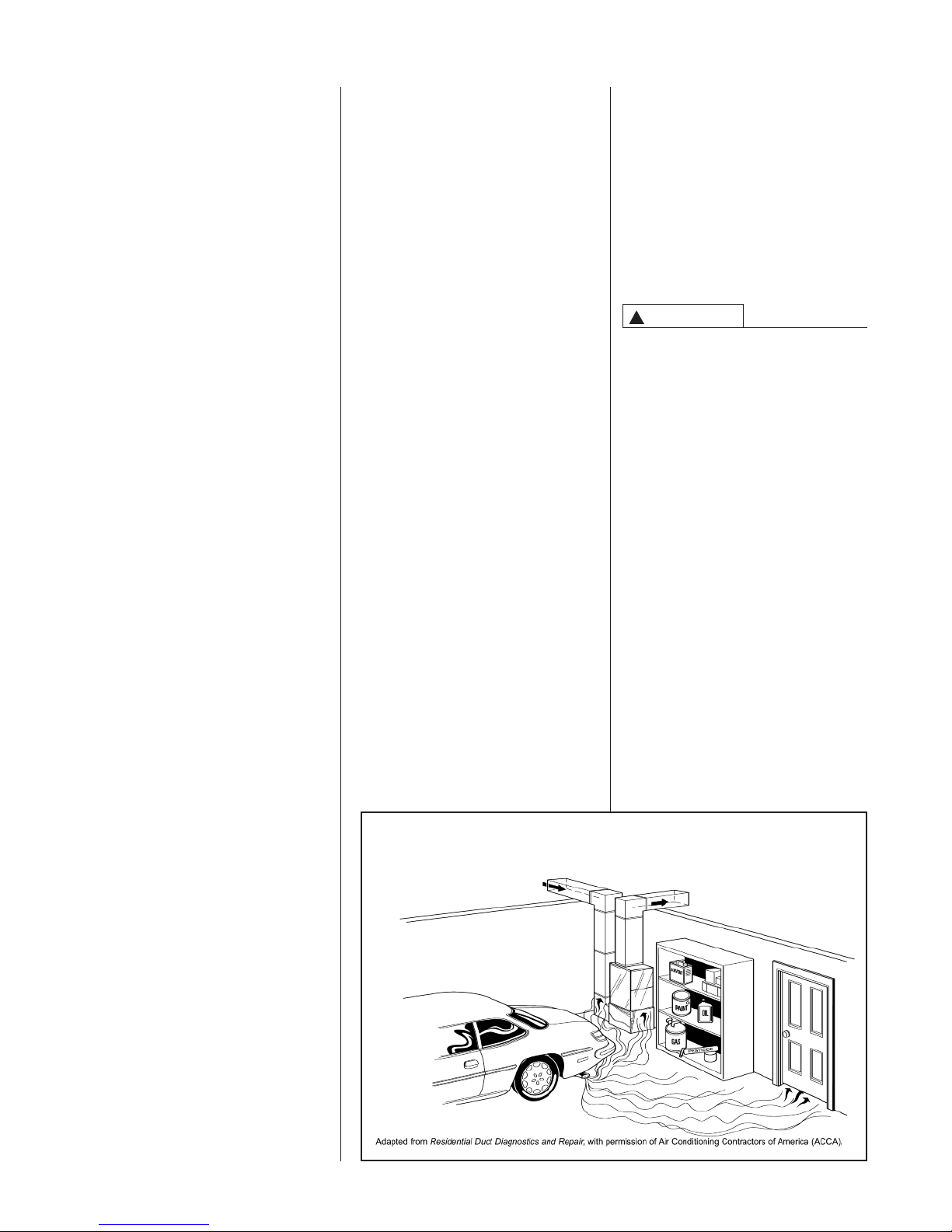
!
DUCT LEAKS CAN CREATE AN
UNBALANCED SYSTEM AND
DRAW POLLUTANTS SUCH AS
DIRT, DUST, FUMES AND ODORS
INTO THE HOME CAUSING
ROPERTY DAMAGE. FUMES
P
AND ODORS FROM TOXIC,
VOLATILE OR FLAMMABLE
CHEMICALS, AS WELL AS
AUTOMOBILE EXHAUST AND
CARBON MONOXIDE (CO), CAN
BE DRAWN INTO THE LIVING
SPACE THROUGH LEAKING
DUCTS AND UNBALANCED DUCT
YSTEMS CAUSING PERSONAL
S
INJURY OR DEATH (SEE FIGURE
1).
• IF AIR-MOVING EQUIPMENT OR
DUCTWORK IS LOCATED IN
GARAGES OR OFF-GARAGE
STORAGE AREAS - ALL JOINTS,
SEAMS, AND OPENINGS IN THE
EQUIPMENT AND DUCT MUST
BE SEALED TO LIMIT THE
MIGRATION OF TOXIC FUMES
AND ODORS INCLUDING
CARBON MONOXIDE FROM
MIGRATING INTO THE LIVING
SPACE.
• IF AIR-MOVING EQUIPMENT OR
DUCTWORK IS LOCATED IN
SPACES CONTAINING FUEL
BURNING APPLIANCES SUCH
AS WATER HEATERS OR
BOILERS - ALL JOINTS, SEAMS,
AND OPENINGS IN THE
EQUIPMENT AND DUCT MUST
ALSO BE SEALED TO PREVENT
DEPRESSURIZATION OF THE
SPACE AND POSSIBLE
MIGRATION OF COMBUSTION
BYPRODUCTS INCLUDING
CARBON MONOXIDE INTO THE
LIVING SPACE.
NOTICE
IMPROPER INSTALLATION, OR
INSTALLATION NOT MADE IN
ACCORDANCE WITH THE CSA
INTERNATIONAL (CSA)
CERTIFICATION OR THESE
INSTRUCTIONS, CAN RESULT IN
NSATISFACTORY OPERATION
U
AND/OR DANGEROUS CONDITIONS AND ARE NOT COVERED
BY THE UNIT WARRANTY.
NOTICE
IN COMPLIANCE WITH
RECOGNIZED CODES, IT IS
RECOMMENDED THAT AN
AUXILIARY DRAIN PAN BE
INSTALLED UNDER ALL
EVAPORATOR COILS OR UNITS
CONTAINING EVAPORATOR
COILS THAT ARE LOCATED IN
ANY AREA OF A STRUCTURE
WHERE DAMAGE TO THE
BUILDING OR BUILDING
CONTENTS MAY OCCUR AS A
RESULT OF AN OVERFLOW OF
THE COIL DRAIN PAN OR A
STOPPAGE IN THE PRIMARY
CONDENSATE DRAIN PIPING. SEE
ACCESSORIES SECTION OF
THESE INSTRUCTIONS FOR
AUXILIARY HORIZONTAL
OVERFLOW PAN INFORMATION
(MODEL RXBM).
5
GENERAL INFORMATION
The (-)GPT/(-)GLT series furnaces are
design certified by CSA for use with
natural and propane gases as follows:
As a Category I furnace, it may be
vented vertically with type B-1 vent
pipe and also may be common
vented as described in these
instructions.
This furnace should be installed in
accordance with the American National
Standard Z223.1 - latest edition booklet
entitled “National Fuel Gas Code”
(NFPA 54) (in Canada, CSA B149.1
and .2 Installation Codes for gas
burning appliances), and the
requirements or codes of the local utility
or other authority having jurisdiction
including local plumbing or waste water
codes.
The National Appliance Energy
Conservation Act (NAECA) of 1987
states that any gas furnace
manufactured after January 1, 1992,
must have a minimum Annual Fuel
Utilization Efficiency (AFUE) of 78%.
The higher the AFUE percentage the
more usable heat energy the consumer
gets for every dollar of fuel purchased.
This is similar to the EPA's minimum
gas mileage requirement for
automobiles. It gives the consumer a
relatively easy way to make direct
efficiency comparisons between
different furnace brands and styles.
A high AFUE value, which translates
into a low operating cost, is not the only
concern that consumers have. They
also want a furnace with a reasonable
installed cost. They want a furnace that
provides them with comfort – their main
concern. And they expect a furnace with
exceptional reliability and longevity.
Gas furnace manufacturers are always
striving to provide consumers with the
best furnace value. The Low Profile
Furnace addresses all those consumer
needs. It gives exceptional efficiency
with a low installation cost. It delivers
the comfort the customer wants along
with the reliability they expect.
The key to all these customer benefits is
the furnace's heat exchanger. The
materials used to construct the furnace
in general and the heat exchanger in
particular make it a rugged, long lasting
unit. The unique heat exchanger design
provides the customer with a furnace
only 34 inches high. This gives the
consumer a unit easily installed in
almost every location that accepts all
customary accessories.
With the introduction of higher efficiency
furnaces, special attention must be paid
to the venting system. Only listed
venting systems may be used as stated
in the installation instructions and the
National Fuel Gas Code, ANSI Z223.1
(NFPA 54), or the Canadian CAN/CGA
B149.1 and B149.2 Installation Codes
for Gas Burning Appliances. Since
furnace technology and venting
requirements are changing, awareness
of local, state, and federal codes and
industry changes is imperative.
NOTE: Always perform a proper heat
loss calculation before specifying the
furnace size. This ensures that the
furnace is sized to adequately,
economically, heat the building and
provide the correct airflow for your
application.
IMPORTANT: PROPER
APPLICATION, INSTALLATION AND
MAINTENANCE OF THIS FURNACE
IS A MUST IF CONSUMERS ARE TO
RECEIVE THE FULL BENEFITS FOR
WHICH THEY HAVE PAID.
Additional helpful publications available
from the “National Fire Protection
Association” are: NFPA-90A –
Installation of Air Conditioning and
Ventilating Systems 1985 or latest
edition. NFPA-90B – Warm Air Heating
and Air Conditioning Systems 1984.
These publications are available from:
National Fire Protection Association,
Inc.
Batterymarch Park
Quincy, MA 02269
CSA-INTERNATIONAL
178 Rexdale Blvd.
Etobicoke (Toronto), Ontario
Canada M9W, 1R3
IMPORTANT INFORMATION
ABOUT EFFICIENCY AND
INDOOR AIR
QUALITY
Central cooling and heating equipment
is only as efficient as the duct system
that carries the cooled or heated air.
To maintain efficiency, comfort and
good indoor air quality, it is important
to have the proper balance between
the air being supplied to each room
and the air returning to the cooling and
heating equipment.
FIGURE 1
MIGRATION OF DANGEROUS SUBSTANCES, FUMES, AND ODORS INTO LIVING SPACES
Proper balance and sealing of the duct
system improves the efficiency of the
heating and air conditioning system
and improves the indoor air quality of
the home by reducing the amount of
airborne pollutants that enter homes
from spaces where the ductwork and /
or equipment is located. The
manufacturer and the U.S.
Environmental Protection Agency’s
Energy Star Program recommend that
central duct systems be checked by a
qualified contractor for proper balance
and sealing.
WARNING
!
DUCT LEAKS CAN CREATE AN
UNBALANCED SYSTEM AND DRAW
POLLUTANTS SUCH AS DIRT,
DUST, FUMES AND ODORS INTO
THE HOME CAUSING PROPERTY
DAMAGE. FUMES AND ODORS
FROM TOXIC, VOLATILE OR
FLAMMABLE CHEMICALS, AS
WELL AS AUTOMOBILE EXHAUST
AND CARBON MONOXIDE (CO),
CAN BE DRAWN INTO THE LIVING
SPACE THROUGH LEAKING DUCTS
AND UNBALANCED DUCT
SYSTEMS CAUSING PERSONAL
INJURY OR DEATH (SEE FIGURE 1).
• IF AIR-MOVING EQUIPMENT OR
DUCTWORK IS LOCATED IN
GARAGES OR OFF-GARAGE
STORAGE AREAS - ALL JOINTS,
SEAMS, AND OPENINGS IN THE
EQUIPMENT AND DUCT MUST BE
SEALED TO LIMIT THE
MIGRATION OF TOXIC FUMES
AND ODORS INCLUDING
CARBON MONOXIDE FROM
MIGRATING INTO THE LIVING
SPACE.
• IF AIR-MOVING EQUIPMENT OR
DUCTWORK IS LOCATED IN
SPACES CONTAINING FUEL
BURNING APPLIANCES SUCH AS
WATER HEATERS OR BOILERS -
6
ALL JOINTS, SEAMS, AND
OPENINGS IN THE EQUIPMENT
AND DUCT MUST ALSO BE
SEALED TO PREVENT
DEPRESSURIZATION OF THE
SPACE AND POSSIBLE
MIGRATION OF COMBUSTION
BYPRODUCTS INCLUDING
CARBON MONOXIDE INTO THE
LIVING SPACE.
NOTICE
IMPROPER INSTALLATION, OR
INSTALLATION NOT MADE IN
ACCORDANCE WITH THE CSA
INTERNATIONAL (CSA)
CERTIFICATION OR THESE
INSTRUCTIONS, CAN RESULT IN
UNSATISFACTORY OPERATION
AND/OR DANGEROUS CONDITIONS AND ARE NOT COVERED BY
THE UNIT WARRANTY.
NOTICE
IN COMPLIANCE WITH
RECOGNIZED CODES, IT IS
RECOMMENDED THAT AN
AUXILIARY DRAIN PAN BE
INSTALLED UNDER ALL
EVAPORATOR COILS OR UNITS
CONTAINING EVAPORATOR COILS
THAT ARE LOCATED IN ANY AREA
OF A STRUCTURE WHERE
DAMAGE TO THE BUILDING OR
BUILDING CONTENTS MAY OCCUR
AS A RESULT OF AN OVERFLOW
OF THE COIL DRAIN PAN OR A
STOPPAGE IN THE PRIMARY
CONDENSATE DRAIN PIPING. SEE
ACCESSORIES SECTION OF THESE
INSTRUCTIONS FOR AUXILIARY
HORIZONTAL OVERFLOW PAN
INFORMATION (MODEL RXBM).
RECEIVING
Immediately upon receipt, all cartons
and contents should be inspected for
transit damage. Units with damaged
cartons should be opened immediately.
If damage is found, it should be noted
on the delivery papers, and a damage
claim filed with the last carrier.
After unit has been delivered to job
•
ite, remove carton taking care not
s
o damage unit.
t
• Check the unit rating plate for unit
size, electric heat, coil, voltage,
phase, etc. to be sure equipment
matches what is required for the job
specification.
• Read the entire instructions before
starting the installation.
• Some building codes require extra
cabinet insulation and gasketing
when unit is installed in attic
applications.
• If installed in an unconditioned
space, apply caulking around the
power wires, control wires,
refrigerant tubing and condensate
line where they enter the cabinet.
Seal the power wires on the inside
where they exit conduit opening.
Caulking is required to prevent air
leakage into and condensate from
forming inside the unit, control box,
and on electrical controls.
• Install the unit in such a way as to
allow necessary access to the
coil/filter rack and blower/control
compartment.
• Install the unit in a level position to
ensure proper condensate drainage.
Make sure unit is level in both
directions within 1/8”.
Install the unit in accordance with
•
ny local code which may apply and
a
he national codes. Latest editions
t
re available from: “National Fire
a
rotection Association, Inc.,
P
Batterymarch Park, Quincy, MA
02269.” These publications are:
• ANSI/NFPA No. 70-(Latest Edition)
National Electrical Code.
• NFPA90A Installation of Air
Conditioning and Ventilating
Systems.
• NFPA90B Installation of warm air
heating and air conditioning
systems.
• The equipment has been evaluated
in accordance with the Code of
Federal Regulations, Chapter XX,
Part 3280.
LOCATION REQUIREMENTS AND CONSIDERATIONS
GENERAL INFORMATION
1. NOTE: This furnace is shipped with
heat exchanger support brackets
installed under the back of the heat
exchanger. These may be removed
before installation, but it is not
required.
LOCATION
!
WARNING
THIS FURNACE IS NOT APPROVED
FOR INSTALLATION IN A MOBILE
HOME. DO NOT INSTALL THIS
FURNACE IN A MOBILE HOME.
INSTALLATION IN A MOBILE HOME
COULD CAUSE FIRE, PROPERTY
DAMAGE, PERSONAL INJURY OR
DEATH.
2. IMPORTANT: This furnace is not
approved or recommended for
installation on its back, with access
doors facing upwards.
3. This furnace is suitable for
installation in buildings constructed
on-site. This heating unit should be
centralized with respect to the heat
distribution system as much as
practicable.
4. NOTE: These furnaces are
approved for installation in attics, as
well as alcoves, utility rooms,
closets and crawlspaces.
5. IMPORTANT: Support this unit when
installed. For attic or crawl space
installation, horizontal furnaces may
be installed on combustible wood
flooring or by using support brackets.
See Figure 2.
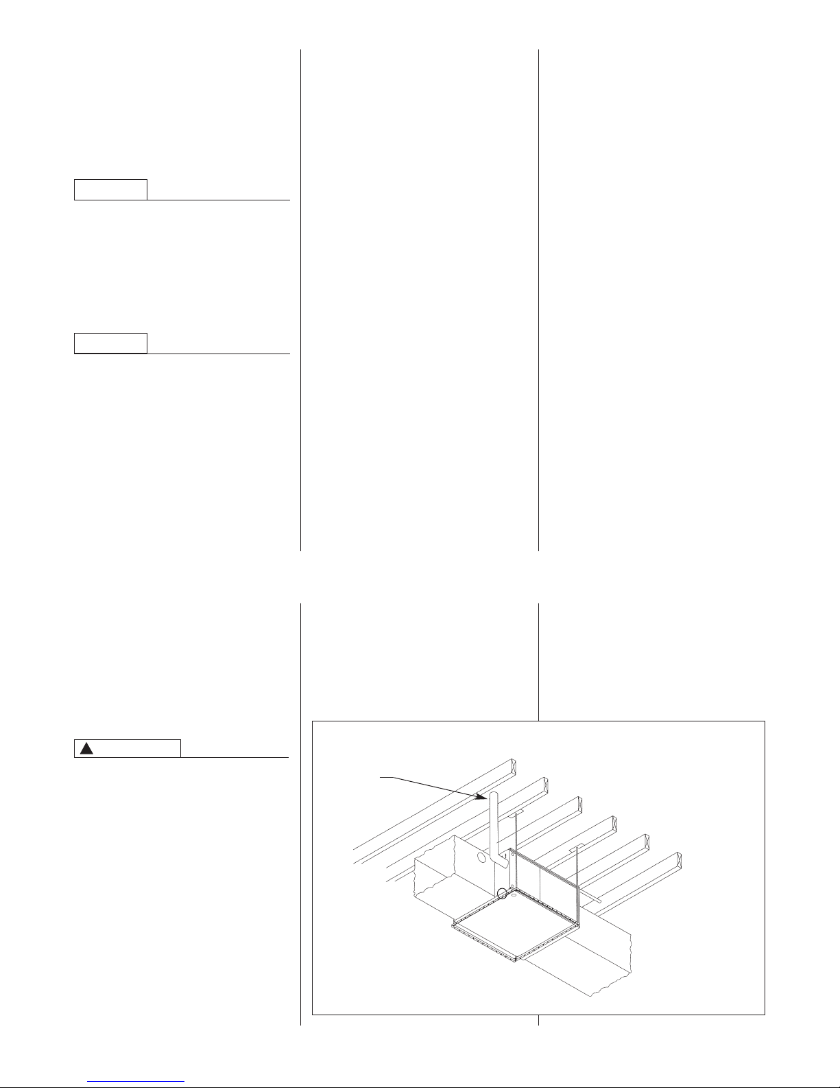
FIGURE 2
HORIZONTAL FURNACE INSTALLED W/SUPPORT BRACKETS
EXHAUST
VENT
NOTE: Do not block furnace
access with support rods. Maintain
clearances recommended in Figure 3.
Allow enough space for proper service
maintenance or replacement of the heat
exchanger and blower assembly.
6. IMPORTANT: If installing in a utility
room, be sure the door is wide
enough to:
a. allow the largest part of the
b. allow any other appliance (such
furnace to pass; or
as a water heater) to pass.
ST-A0799-01
7
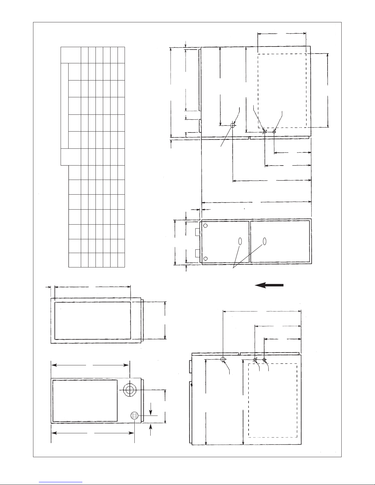
FIGURE 3
PFLOW/HORIZONTAL DIMENSIONS
U
Ship.
/32
19
15
20
/16
1
28
➀ May require 3” to 4” or 3” or 5” adapter.
➁ May be 0” with type B vent.
Back Top Front Vent
REDUCED CLEARANCE (IN.)
Left Right
Side Side Wgts.
/8 0 4➁ 0 1 3 6➂ 85 lbs.
/2 0 3➁ 0 1 3 6➂ 105 lbs.
/2 0 3➁ 0 1 3 6➂ 115 lbs.
/2 0 0 0 1 3 6➂ 120 lbs.
/2 0 0 0 1 3 6➂ 140 lbs.
7
1
1
/2 1
1
/8 ➀ 11
/8 ➀ 15 2
/8 ➀ 15 2
5
3
3
/32 10
/32 12
/32 12
27
11
11
/2 16
/2 16
1
1
/2 0 0 0 1 3 6➂ 150 lbs.
1
1
1
/2 2
1
/8 ➀ 18
/8 ➀ 22 2
/8 ➀ 22 2
1
7
7
/32 14
/32 15
/32 15
27
11
11
/2 23
/2 23
1
1
➂ May be 1” with type B vent.
D
/16
9
/32
19
B
A
/16
7
24
/8
5
26
/8 DIA.
/8 DIA.
5
7
1
/8 DIA.
7
/2
1
23
11
/8
3
14
/32
ALTERNATE
GAS CONNECTION
11
24
RIGHT SIDE
34
/4
3
FRONT
12 24
07 17
05 14 12
UPFLOW/HORIZONTAL MODELS
CLEARANCE TO COMBUSTIBLE MATERIAL (INCHES)
/4
1
1
Model A B C D E F
10(A) 17
/32
17
23
15 24
10(B) 21 19
/32
19
SIGHT
GLASS
AIRFLOW
/32
11
AIR
BOTTOM
RETURN
/2
1
E
24
/16
TOP
AIR
SUPPLY
C
13
26
/8
5
26
GAS CONNECTION
F
25.406
24
/8
3
14
/2
1
11
LOW VOLTAGE
LEFT SIDE
ELECTRICAL CONNECTION
(EITHER SIDE) FOR USE WITH
EXTERNAL SIDE FILTER FRAME
OPTIONAL RETURN AIR CUTOUT
8
IMPORTANT: This furnace is not approved or recommended for
installation on its back, with access doors facing upwards.
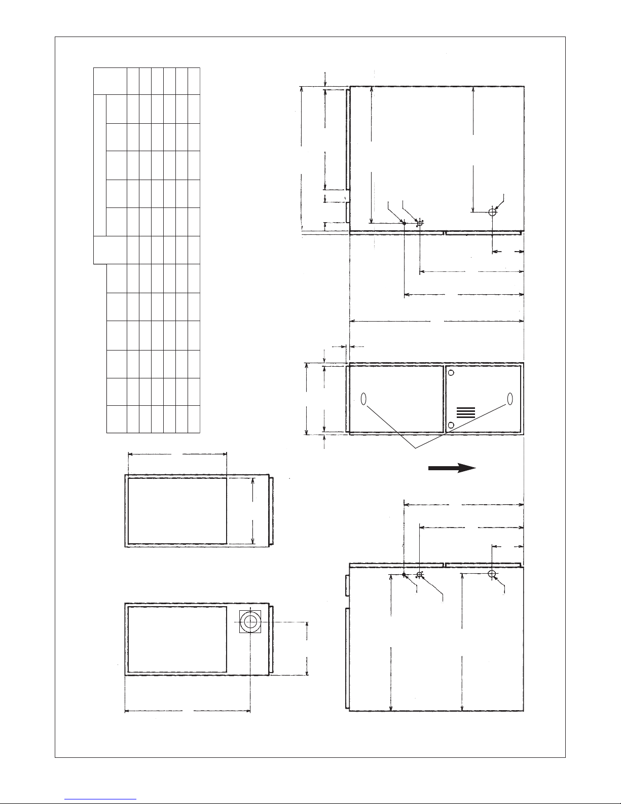
FIGURE 4
DOWNFLOW DIMENSIONS
Ship.
Back Top Front Vent
REDUCED CLEARANCE (IN.)
/8
5
/8
1
20
/16
1
28
➀ May require 3” to 4” or 3” or 5” adapter.
➁ May be 0” with type B vent.
➂ May be 1” with type B vent.
/8
5
26
/8 DIA.
/8 DIA.
7
7
/16
7
24
/8 DIA.
5
1
D
Left Right
Side Side Wgts.
/8
/8 0 4➁ 0 1 3 6➂ 85 lbs.
/8 0 3➁ 0 1 3 6➂ 105 lbs.
/8 0 3➁ 0 1 3 6➂ 115 lbs.
/8 0 0 0 1 3 6➂ 120 lbs.
/8 0 0 0 1 3 6➂ 140 lbs.
1
5
5
/8 0 0 0 1 3 6➂ 150 lbs.
1
5
5
3
20
/8
3
/16
3
6
23
/8 ➀ 13
/8 ➀ 16
/8 ➀ 16
/8 ➀ 20
/8 ➀ 23
3
1
1
/32 10
/32 12
/32 12
27
11
11
/2 16
/2 16
1
1
05 14 12
07 17
DOWNFLOW MODELS
CLEARANCE TO COMBUSTIBLE MATERIAL (INCHES)
Model A B C D E
10(A) 17
/8 ➀ 23
7
5
5
/32 13
/32 15
/32 15
27
11
11
/2 23
/2 23
1
1
12 24
15 24
10(B) 21 19
/4
3
19
/8
5
R.A.
B
A
/8
5
/4
3
SIGHT
34
GLASS
AIRFLOW
S.A.
E
/8
3
23
/8
3
20
/16
3
6
TOP BOTTOM
/2
1
24
/8
5
26
C
LOW VOLTAGE
/16
13
26
GAS CONNECTION
ELECTRIC CONNECTION
NOTE: IN DOWNFLOW CONFIGURATION, OPTIONAL AIR CUTOUT IS NOT PERMITTED.
9
CLEARANCE –
ACCESSIBILITY
The design of forced air furnaces with
nput ratings as listed in the tables on
i
the following pages are certified by
CSA for the clearances to combustible
materials shown in inches.
See name/rating plate and clearance
label for specific model number and
clearance information.
Service clearance of at least 24 inches
is recommended in front of all furnaces.
ACCESSIBILITY CLEARANCES,
WHERE GREATER, MUST TAKE
PRECEDENCE OVER FIRE
PROTECTION CLEARANCES.
!
WARNING
UPFLOW AND HORIZONTAL
FURNACES MUST NOT BE
INSTALLED DIRECTLY ON
CARPETING, TILE OR OTHER
COMBUSTIBLE MATERIAL OTHER
THAN WOOD FLOORING.
INSTALLATION ON A
COMBUSTIBLE MATERIAL CAN
RESULT IN FIRE CAUSING
PROPERTY DAMAGE, SEVERE
PERSONAL INJURY OR DEATH.
A gas-fired furnace for installation in a
residential garage must be installed so
that the burner(s) and the ignition
source are located not less than 18”
above the floor and the furnace is
located or protected to avoid physical
damage by vehicles.
!
WARNING
DOWNFLOW UNIT DESIGN IS
CERTIFIED FOR INSTALLATION ON
NON-COMBUSTIBLE FLOOR. A
SPECIAL COMBUSTIBLE FLOOR
SUB-BASE IS REQUIRED WHEN
INSTALLING ON A COMBUSTIBLE
FLOOR. FAILURE TO INSTALL THE
SUB-BASE MAY RESULT IN FIRE,
PROPERTY DAMAGE, PERSONAL
INJURY OR DEATH. THIS SPECIAL
BASE IS OFFERED AS AN
ACCESSORY FROM THE FACTORY.
SEE THE CLEARANCE LABEL
LOCATED INSIDE THE FURNACE
FOR THE APPROPRIATE MODEL
NUMBER.
THE SPECIAL BASE IS NOT
REQUIRED WHEN THE FURNACE IS
INSTALLED ON TOP OF AN AIR
CONDITIONING PLENUM.
TABLE 1
FURNACE BASE BASE
IDTH
W
1
17
/2” RXGB-D17 151/8” x 239/16”
21” RXGB-D21 18
1
24
/2” RXGB-D24 255/8” x 239/16”
LATE NO.
P
LATE SIZE
P
5
/8” x 239/16”
SITE SELECTION
1. Select a site in the building near the
center of the proposed, or existing,
duct system.
2. Give consideration to the vent system
piping when selecting the furnace
location. Be sure the venting system
can travel from the furnace to the
termination with minimal length and
elbows.
3. Locate the furnace near the existing
gas piping. Or, if running a new gas
line, locate the furnace to minimize
the length and elbows in the gas
piping.
4. Locate the furnace to maintain proper
clearance to combustibles as shown
in Figures 3 and 4.
!
CAUTION
WHEN COILS ARE USED WITH AIR
HANDLERS OR FURNACES AND
INSTALLED ABOVE A FINISHED
CEILING OR LIVING AREA, IT IS
RECOMMENDED THAT AN
AUXILIARY SHEET METAL
CONDENSATE DRAIN PAN BE
FABRICATED AND INSTALLED
UNDER ENTIRE UNIT. FAILURE TO
DO SO CAN RESULT IN PROPERTY
DAMAGE. RUN CONDENSATE TO A
LOCATION WHERE IT IS
NOTICEABLE.
!
WARNING
COMBUSTIBLE MATERIAL MUST
NOT BE PLACED ON OR AGAINST
THE FURNACE JACKET OR WITHIN
THE SPECIFIED CLEARANCES OF
THE VENT PIPE. THE AREA AROUND
THE FURNACE MUST BE KEPT
CLEAR AND FREE OF ALL
COMBUSTIBLE MATERIALS
INCLUDING GASOLINE AND OTHER
FLAMMABLE VAPORS AND LIQUIDS.
PLACEMENT OF COMBUSTIBLE
MATERIALS ON, AGAINST OR
AROUND THE FURNACE JACKET
CAN CAUSE AN EXPLOSION OR
FIRE RESULTING IN PROPERTY
DAMAGE, PERSONAL INJURY OR
DEATH. THE FURNACE OWNER
SHOULD BE CAUTIONED THAT THE
FURNACE AREA MUST NOT BE
USED AS A BROOM CLOSET OR
FOR ANY OTHER STORAGE
PURPOSES.
DUCTING
Proper air flow is required for the
correct operation of this furnace. Too
ittle air flow can cause erratic
l
operation and can damage the heat
exchanger. The duct system must
arry the correct amount of air for
c
heating and cooling. Position the unit
minimize long runs or runs with many
urns and elbows.
t
Size the ducts according to acceptable
industry standards and methods. The
total static pressure drop (including
evaporator coil, if used) of the entire
system should not exceed 0.5” w.c. Be
sure to have adequate space for unit
filter. NOTE: Airflow external static
pressure measurements do not include
filter or coil.
IMPORTANT: Some high efficiency
filters have a greater than normal
resistance to air flow. This can
adversely affect furnace operation. BE
SURE TO CHECK AIR FLOW if using
any filter other than the factoryprovided filter.
NOTE: DO NOT take return air from
bathrooms, kitchens, furnace rooms,
garages, utility or laundry rooms, or
cold areas.
IMPORTANT: When using outside air,
design and adjust the system to
maintain a return air temperature
above 50°F during the heating season.
!
WARNING
NEVER ALLOW PRODUCTS OF
COMBUSTION OR THE FLUE
PRODUCTS TO ENTER THE
RETURN AIR DUCTWORK, OR THE
CIRCULATING AIR SUPPLY. ALL
RETURN DUCTWORK MUST BE
ADEQUATELY SEALED AND
SECURED TO THE FURNACE WITH
SHEET METAL SCREWS, AND
JOINTS TAPED. WHEN A FURNACE
IS MOUNTED ON A PLATFORM,
WITH RETURN THROUGH THE
BOTTOM, IT MUST BE SEALED
AIRTIGHT BETWEEN THE FURNACE
AND THE RETURN AIR PLENUM.
THE RETURN AIR PLENUM MUST
BE PERMANENTLY ENCLOSED.
NEVER USE A DOOR AS A PART OF
THE RETURN AIR PLENUM. THE
FLOOR OR PLATFORM MUST
PROVIDE SOUND PHYSICAL
SUPPORT OF THE FURNACE,
WITHOUT SAGGING, CRACKS,
GAPS, ETC., AROUND THE BASE AS
TO PROVIDE A SEAL BETWEEN
THE SUPPORT AND THE BASE.
10
FAILURE TO PREVENT PRODUCTS
OF COMBUSTION FROM BEING
CIRCULATED INTO THE LIVING
SPACE CAN CREATE POTENTIALLY
HAZARDOUS CONDITIONS,
INCLUDING CARBON MONOXIDE
POISONING THAT COULD RESULT
IN PERSONAL INJURY OR DEATH.
DO NOT, UNDER ANY
CIRCUMSTANCES, CONNECT
ETURN OR SUPPLY DUCTWORK
R
TO OR FROM ANY OTHER HEAT
PRODUCING DEVICE SUCH AS A
IREPLACE INSERT, STOVE, ETC.
F
DOING SO MAY RESULT IN FIRE,
CARBON MONOXIDE POISONING,
XPLOSION, PERSONAL INJURY
E
OR PROPERTY DAMAGE.
!
WARNING
BLOWER AND BURNERS MUST
NEVER BE OPERATED WITHOUT
THE BLOWER DOOR IN PLACE.
THIS IS TO PREVENT DRAWING
GAS FUMES (WHICH COULD
CONTAIN HAZARDOUS CARBON
MONOXIDE) INTO THE HOME THAT
COULD RESULT IN PERSONAL
INJURY OR DEATH.
UPFLOW UNITS
1. Set furnace in place and connect the
return duct or return air cabinet to
unit. Make the connection air-tight to
prevent entraining combustion
gases from any adjacent fuelburning appliances. Unit return air
may be connected on the sides or
bottom of the return air
compartment.
a. Openings in the side must be cut
out the full width of the knockouts
on the unit. If using side return air,
THE BOTTOM base plate must
be installed.
NOTE: Where the maximum
airflow is 1800 CFM or more, both
sides or the bottom must be used
for return air.
b. If using bottom return air, place
furnace over return air plenum and
seal furnace bottom to return air
plenum.
!
WARNING
A SOLID METAL BASE PLATE, (SEE
TABLE 1) MUST BE IN PLACE
WHEN THE FURNACE IS
INSTALLED WITH SIDE AIR
RETURN DUCTS. FAILURE TO
INSTALL A BASE PLATE COULD
CAUSE PRODUCTS OF
COMBUSTION TO BE CIRCULATED
NTO THE LIVING SPACE AND
I
CREATE POTENTIALLY
HAZARDOUS CONDITIONS,
INCLUDING CARBON MONOXIDE
POISONING OR DEATH.
2. If summer air conditioning is desired,
position the indoor coil on the supply
air side of the furnace. Insure that no
air can bypass this coil.
3. Connect the supply air plenum to the
furnace plenum opening.
DOWNFLOW UNITS
!
WARNING
THE DOWNFLOW FURNACE
DESIGN IS CERTIFIED FOR
INSTALLATION ON A NONCOMBUSTIBLE FLOOR. IF
INSTALLED ON A COMBUSTIBLE
FLOOR, USE THE SPECIAL BASE
SPECIFIED ON THE FURNACE
CLEARANCE LABEL. FAILURE TO
INSTALL THE SPECIAL BASE MAY
RESULT IN FIRE, PROPERTY
DAMAGE, PERSONAL INJURY OR
DEATH. THIS SPECIAL BASE IS
SHIPPED FROM THE FACTORY AS
AN ACCESSORY.
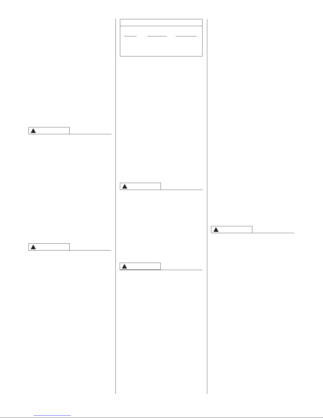
1. Position the unit over the supply air
plenum and connect.
a. If installing on a combustible floor
and not using an evaporator
coil box, install the special
combustible floor base. See
Figure 5.
FIGURE 5
COMBUSTIBLE FLOOR BASE
b. If summer air conditioning is
desired, position the indoor coil on
the bottom of the unit. Insure that
no air can bypass this coil.
2. Connect the return air ducting to the
return air opening at the top of the
unit. Make the connection air tight to
revent entraining combustion
p
gases from an adjacent fuel-burning
appliance.
HORIZONTAL UNITS
1. Unit can be mounted left or right
side airflow configuration.
2. Position the unit on adequate
supports or by using support
brackets (see Figure 3) and connect
supply plenum.
3. If summer air conditioning is desired,
position the indoor coil on the supply
air side of the unit. Insure that no air
can bypass this coil.
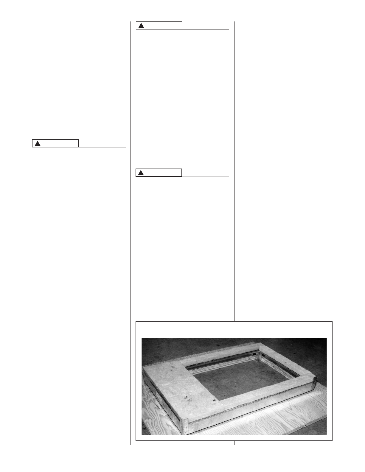
4. Secure the four angle brackets
shipped with the unit to the return air
opening. See Figure 7. Connect the
return air ducting to the return air
opening at the top of the unit. Make
the connection air tight to prevent
entraining combustion gases from
an adjacent fuel-burning appliance.
NOTE: Do not block furnace access
with support rods. Maintain clearances
recommended in Figure 3. Allow
enough space for proper service
maintenance or replacement of the
heat exchanger and blower assembly.
11
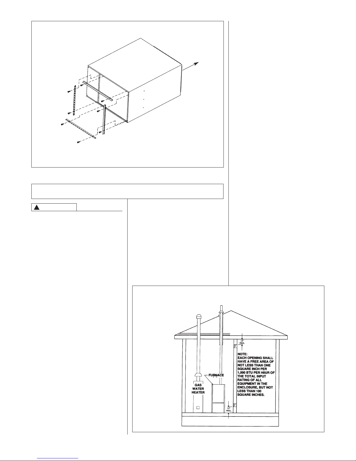
FIGURE 6
HORIZONTAL RETURN AIR DUCT
LEFT-HAND AIRFLOW POSITION SHOWN)
(
IRFLOW
A
ETURN
R
REAR VIEW
FOUR ANGLE BRACKETS ARE SHIPPED WITH EACH
NIT THAT CAN BE INSTALLED HORIZONTALLY. THESE
U
BRACKETS MAY BE USED TO SECURE THE RETURN
AIR DUCT TO A HORIZONTAL UNIT.
COMBUSTION AND VENTILATION AIR
IMPORTANT: This is not a direct vent furnace. Review venting instructions
before installing.
• Commercial buildings
• Buildings with indoor pools
• Furnaces installed in laundry rooms
• Furnaces in hobby or craft rooms
• Furnaces installed near chemical
storage areas.
Exposure to the following substances
n the combustion air supply may also
i
require OUTDOOR AIR for
combustion:
• Permanent wave solutions
• Chlorinated waxes and cleaners
• Chlorine-based swimming pool
chemicals
• Water softening chemicals
• De-icing salts or chemicals
• Carbon tetrachloride
• Halogen type refrigerants
• Cleaning solvents (such as
perchloroethylene)
• Printing inks, paint removers,
varnishes, etc.
• Hydrochloric acid
• Cements and glues
• Antistatic fabric softeners for clothes
dryers
• Masonry acid washing materials
!
WARNING
THIS FURNACE AND ANY OTHER
FUEL-BURNING APPLIANCE MUST
BE PROVIDED WITH ENOUGH
FRESH AIR FOR PROPER
COMBUSTION AND VENTILATION
OF THE FLUE GASES. MOST
HOMES WILL REQUIRE THAT
OUTSIDE AIR BE SUPPLIED INTO
THE FURNACE AREA. FAILURE TO
DO SO CAN CAUSE DEATH FROM
CARBON MONOXIDE POISONING.
Adequate facilities for providing air for
combustion and ventilation must be
provided in accordance with section
5.3, Air for Combustion and
Ventilation, of the National Fuel Gas
Code, ANSI, Z223.1 latest edition or
CSA B149.1 and .2 or, applicable
provisions for the local building codes,
and not obstructed so as to prevent the
flow of air to the furnace.
COMBUSTION AIR
REQUIREMENTS
IMPORTANT: Air for combustion and
ventilation must not come from a
corrosive atmosphere. Any failure due
to corrosive elements in the
atmosphere is excluded from warranty
coverage.
The following types of installation may
require OUTDOOR AIR for
combustion, due to chemical
exposures:
FIGURE 7
AIR FROM HEATED SPACE
12
 Loading...