

Page 1
92-23531-70-01
SUPERSEDES 92-23531-70-00
INSTALLATION INSTRUCTIONS
FOR UPFLOW (RGDG & RGDJ), UPFLOW/HORIZONTAL
(RGPH & RGPJ), HORIZONTAL ONLY (RGVH & RGVJ)
AND DOWNFLOW (RGLH & RGLJ) INDUCED DRAFT
GAS FURNACES
!
If the information in these instructions is not followed exactly, a
fire or explosion may result, causing property damage, personal
injury or death.
THESE INSTRUCTIONS ARE
INTENDED AS AN AID TO
QUALIFIED SERVICE
PERSONNEL FOR PROPER
INSTALLATION, ADJUSTMENT
AND OPERATION OF THIS
UNIT. READ THESE
INSTRUCTIONS THOROUGHLY
BEFORE ATTEMPTING
INSTALLATION OR
OPERATION. FAILURE TO
FOLLOW THESE
INSTRUCTIONS MAY RESULT
IN IMPROPER INSTALLATION,
ADJUSTMENT, SERVICE OR
MAINTENANCE, POSSIBLY
RESULTING IN FIRE,
ELECTRICAL SHOCK, CARBON
MONOXIDE POISONING,
EXPLOSION, PROPERTY
DAMAGE, PERSONAL INJURY
OR DEATH.
Do Not Destroy this Manual.
Please read carefully and keep
in a safe place for future
reference by a serviceman.
WARNING
Recognize this symbol as an indication of Important Safety Information!
!
— Do not store or use gasoline or other
flammable vapors and liquids, or other
combustible materials in the vicinity of this
or any other appliance.
— WHAT TO DO IF YOU SMELL GAS
• Do not try to light any appliance.
• Do not touch any electrical switch; do not
use any phone in your building.
• Immediately call your gas supplier from a
neighbor’s phone. Follow the gas
supplier’s instructions.
• If you cannot reach your gas supplier,
call the fire department.
• Do not return to your home until
authorized by the gas supplier or fire
department.
— DO NOT RELY ON SMELL ALONE TO
DETECT LEAKS. DUE TO VARIOUS
FACTORS, YOU MAY NOT BE ABLE TO
SMELL FUEL GASES.
• U.L. recognized fuel gas and CO
detectors are recommended in all
applications, and their installation should
be in accordance with the manufacturer’s
recommendations and/or local laws,
rules, regulations, or customs
— Improper installation, adjustment, alteration,
service or maintenance can cause injury,
property damage or death. Refer to this
manual. Installation and service must be
performed by a qualified installer, service
agency or the gas supplier.
WARNING
!
PROPOSITION 65: THIS FURNACE CONTAINS FIBERGLASS
INSULATION. RESPIRABLE PARTICLES OF FIBERGLASS ARE
KNOWN TO THE STATE OF CALIFORNIA TO CAUSE CANCER.
EXHAUST GAS FROM THIS FURNACE CONTAINS CHEMICALS,
INCLUDING CARBON MONOXIDE, KNOWN TO THE STATE OF
CALIFORNIA TO CAUSE BIRTH DEFECTS OR OTHER REPRODUCTIVE HARM.
WARNING
!
FOR YOUR SAFETY
!
Page 2

2
Before beginning any troubleshooting procedure, complete the following installation checklist. A furnace malfunction is
sometimes caused by an improper installation. By completing this checklist, the problem may be found and corrected. Make
copies of the checklist and complete one for every Low Profile Furnace service call for your records.
INSTALLATION CHECKLIST
(Refer to this manual for specifics.)
GAS SUPPLY
Adequate pipe size
No gas leaks
Proper supply and manifold gas pressure (check with an accurate U-tube manometer with the furnace and all other gas
appliances operating.)
ELECTRICAL
Correct thermostat and subbase Thermostat model Subbase model
Correct thermostat mode and setting
Correct line supply voltage
Correct polarity (important with hot surface ignition)
Correct furnace ground to electrical panel
DC microamp (
µA) flame signal (hot surface ignition units)
Correct control voltage
Measure and set heat anticipator amperage
Air conditioning low voltage wires connected to terminals “Y” “C” - not with wire nuts
VENTING
Correct vent pipe diameter and length (according to AGA/GAMA tables) Vent connection size
Correct venting material (according to AGA/GAMA tables)
Correct lining for masonry chimneys
Adequate clearance from combustibles
Proper negative pressure reading in the vent
Vent pipe secured to induced draft blower housing
COMBUSTION AIR
Proper source of combustion air
Correct combustion air opening size
FURNACE INSTALLATION
Adequate clearance from combustibles
Adequate clearance for service
Proper air temperature rise (See furnace rating plate)
External static pressure inches w.c.
Correct filter(s)
Correct cooling coil or accessories (if equipped)
Adequate supply and return air ducting Return Air Duct Size Supply Air Duct Size
Air ducts sealed to prevent leakage
Page 3

3
IMPORTANT: TO INSURE PROPER INSTALLATION AND OPERATION OF
THIS PRODUCT, COMPLETELY READ ALL INSTRUCTIONS PRIOR TO
ATTEMPTING TO ASSEMBLE, INSTALL, OPERATE, MAINTAIN OR REPAIR
THIS PRODUCT. UPON UNPACKING OF THE FURNACE, INSPECT ALL
PARTS FOR DAMAGE PRIOR TO INSTALLATION AND START-UP.
CONTENTS
Safety Precautions...................................................................................................1
Installation Check List ..............................................................................................2
Location Requirements and Considerations............................................................4
Combustion and Ventilation Air..............................................................................10
Vent Pipe Installation..............................................................................................13
Gas Supply and Piping...........................................................................................16
Electrical Wiring......................................................................................................20
Accessories............................................................................................................21
Start-Up Procedures...............................................................................................26
Air Flow...................................................................................................................29
Maintenance...........................................................................................................34
Troubleshooting......................................................................................................36
Wiring Diagrams.....................................................................................................43
➤ Installation Instructions are updated on a regular basis. This is done as
product changes occur or if new information becomes available. In this
publication, an arrow (➤) denotes changes from the previous edition or additional
new material.
Page 4
GENERAL INFORMATION
1. IMPORTANT: If furnace operation
is required during construction, and
air ladened with corrosive
compounds such as chlorine and
fluorine are present, provisions
must be taken to provide clean
outdoor combustion and ventilation
air to the furnace. Compounds of
chlorine and fluorine, when burned
with combustion air, form acids
which will cause corrosion of a heat
exchanger. Some of these
compounds are found in paneling,
dry wall, tile adhesives, paints,
stains and varnishes, solvents and
masonry cleaning materials.
2. NOTE: This furnace is shipped with
heat exchanger support brackets
installed under the back of the heat
exchanger. These may be removed
before installation, but it is not
required.
LOCATION
THIS FURNACE IS NOT APPROVED
FOR INSTALLATION IN A MOBILE
HOME. DO NOT INSTALL THIS
FURNACE IN A MOBILE HOME.
INSTALLATION IN A MOBILE HOME
COULD CAUSE FIRE, PROPERTY
DAMAGE, PERSONAL INJURY OR
DEATH.
3.
IMPORTANT: This furnace is not
approved or recommended for
installation on its back, with access
doors facing upwards.
4. This furnace is suitable for
installation in buildings constructed
on-site. This heating unit should be
centralized with respect to the heat
distribution system as much as
practicable. When installed in a
utility room, the door of the room
should be wide enough to allow the
largest part of the furnace to enter,
or to permit the replacement of
another appliance, such as a water
heater.
5. IMPORTANT: If installing the unit
over a finished ceiling or living
area, be certain to install an
auxiliary condensate drain pan
under any evaporator coil installed
with the furnace.
6. NOTE: These furnaces are
approved for installation in attics, as
well as alcoves, utility rooms,
closets and crawlspaces. Provisions
must be made to prevent freezing of
condensate.
7. IMPORTANT: Support this unit
when installed. Since this furnace
is suitable for attic or crawl space
installation, it may be installed on
combustible wood flooring or by
using support brackets. See Figure
1.
8. IMPORTANT: If installing in a
utility room, be sure the door is
wide enough to:
a. allow the largest part of the
furnace to pass; or
b. allow any other appliance (such
as a water heater) to pass.
4
The RGDG/RGDJ/RGLH/RGLJ and
RGPH/RGPJ/RGVH/RGVJ series
furnaces are design certified by
AGA/CGA for use with natural and
propane gases as follows:
As a Category I furnace, it may be
vented vertically with type B-1 vent
pipe and also may be common
vented as described in these
instructions.
This furnace should be installed in
accordance with the American National
Standard Z223.1 - latest edition booklet
entitled “National Fuel Gas Code”
(NFPA 54) (in Canada, CAN/CGA
B149.1 and .2 Installation Codes for
gas burning appliances), and the
requirements or codes of the local utility
or other authority having jurisdiction
including local plumbing or waste water
codes.
Additional helpful publications available
from the “National Fire Protection
Association” are: NFPA-90A –
Installation of Air Conditioning and
Ventilating Systems 1985 or latest
edition. NFPA-90B – Warm Air Heating
and Air Conditioning Systems 1984.
These publications are available from:
National Fire Protection Association,
Inc.
Batterymarch Park
Quincy, MA 02269
Canadian Gas Association
178 Rexdale Blvd.
Etobicoke (Toronto), Ontario
Canada M9W, 1R3
GENERAL INFORMATION
LOCATION REQUIREMENTS AND CONSIDERATIONS
WARNING
!
FIGURE 1
HORIZONTAL FURNACE INSTALLED W/SUPPORT BRACKETS
EXHAUST
VENT
GAS
PIPE
ELECTRICAL
CONDUIT
ST-A0799-01
Page 5
5
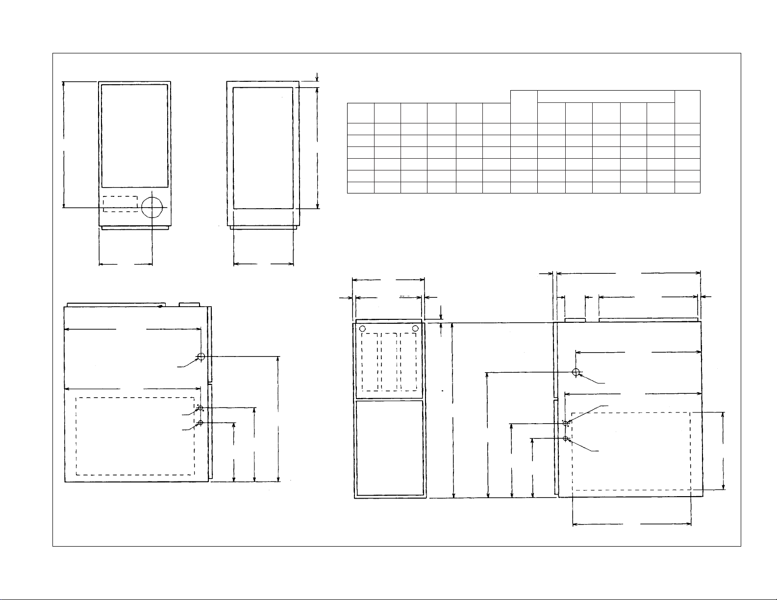
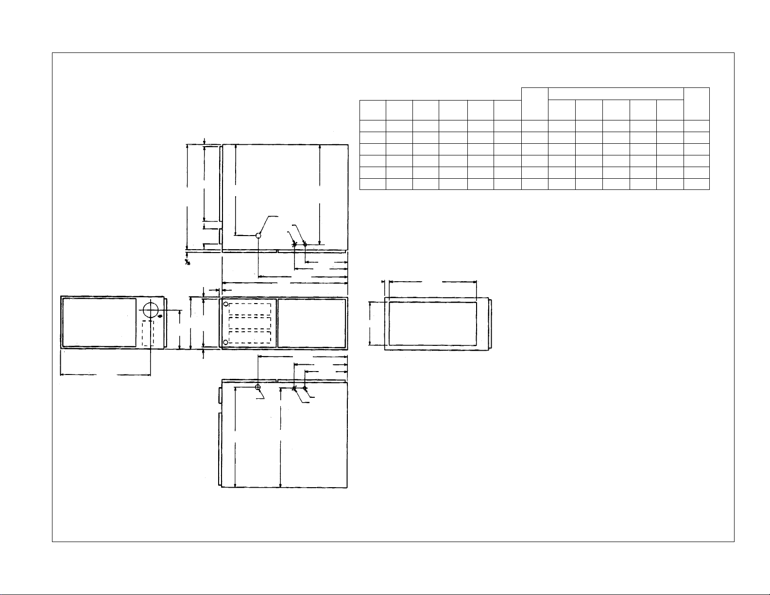
REDUCED CLEARANCE (IN.)
Model A B C D E
Left Right
Back Top Front Vent
Ship.
Side Side Wgts.
04, 05 14 12
27
⁄32 103⁄8 ➀ 111⁄2 0 4➁ 0 1 3 6➂ 85 lbs.
06, 07 17
1
⁄2 1611⁄32 121⁄8 ➀ 15 0 3➁ 0 1 3 6➂ 105 lbs.
10(A) 17
1
⁄2 1611⁄32 121⁄8 ➀ 15 0 3➁ 0 1 3 6➂ 115 lbs.
10(B) 21 19
27
⁄32 137⁄8 ➀ 181⁄2 0 0 0 1 3 6➂ 120 lbs.
12 24
1
⁄2 2311⁄32 155⁄8 ➀ 22 0 0 0 1 3 6➂ 140 lbs.
15 24
1
⁄2 2311⁄32 155⁄8 ➀ 22 0 0 0 1 3 6➂ 150 lbs.
CLEARANCE TO COMBUSTIBLE MATERIAL (INCHES)
UPFLOW AND UPFLOW/HORIZONTAL MODELS
TOP
LEFT SIDE
FRONT
RIGHT SIDE
BOTTOM
24
1
⁄2
26
13
⁄16
26
5
⁄8
24
11
⁄32
24
11
⁄32
19
⁄32
9
⁄16
24
7
⁄16
28
1
⁄16
26
5
⁄8
14
3
⁄8
11
1
⁄2
34
1
3
⁄8 DIA.
23
15
20
D
7
⁄8 DIA.
7
⁄8 DIA.
19
⁄32
19
⁄32
3
⁄4
14
3
⁄8
11
1
⁄2
1
1
⁄4
23
17
⁄32
C
GAS CONNECTION
ELECTRICAL CONNECTION
OPTIONAL RETURN AIR CUTOUT
(EITHER SIDE) FOR USE WITH
EXTERNAL SIDE FILTER FRAME
LOW VOLTAGE
E
A
B
R.A.
S.A.
➀ May require 3( to 4( or 3( or 5( adapter.
➁ May be 0( with type B vent.
➂ May be 1( with type B vent.
FIGURE 2
UPFLOW AND UPFLOW/HORIZONTAL DIMENSIONS
Page 6
6
FIGURE 3
REDUCED CLEARANCE (IN.)
Model A B C D E
Left Right
Back Top Front Vent
Ship.
Side Side Wgts.
04, 05 14 12
27
⁄32 103⁄8 ➀ 13 1⁄8 0 4➁ 0 1 3 6➂ 85 lbs.
06, 07 17
1
⁄2 1611⁄32 121⁄8 ➀ 16 5⁄8 0 3➁ 0 1 3 6➂ 105 lbs.
10(A) 17
1
⁄2 1611⁄32 121⁄8 ➀ 16 5⁄8 0 3➁ 0 1 3 6➂ 115 lbs.
10(B) 21 19
27
⁄32 137⁄8 ➀ 20 1⁄8 0 0 0 1 6 6➂ 120 lbs.
12 24
1
⁄2 2311⁄32 155⁄8 ➀ 23 5⁄8 0 0 0 1 3 6➂ 140 lbs.
15 24
1
⁄2 2311⁄32 155⁄8 ➀ 23 5⁄8 0 0 0 1 3 6➂ 150 lbs.
TOP
BOTTOM
24
1
⁄2
19
3
⁄4
C
A
B
D
LOW VOLTAGE
GAS CONNECTION
ELECTRIC CONNECTION
E
S.A.
R.A.
26
5
⁄8
26
13
⁄16
6
3
⁄16
20
3
⁄8
23
3
⁄8
5
⁄8
5
⁄8
3
⁄4
5
⁄8
34
23
3
⁄8
20
3
⁄8
6
3
⁄16
24
7
⁄16
26
5
⁄8
20
1
⁄8
28
1
⁄16
7
⁄8 DIA.
1
⁄2 DIA.
1
3
⁄8 DIA.
➀ May require 3( to 4( or 3( or 5( adapter.
➁ May be 0( with type B vent.
➂ May be 1( with type B vent.
CLEARANCE TO COMBUSTIBLE MATERIAL (INCHES)
DOWNFLOW MODELS
Page 7
7
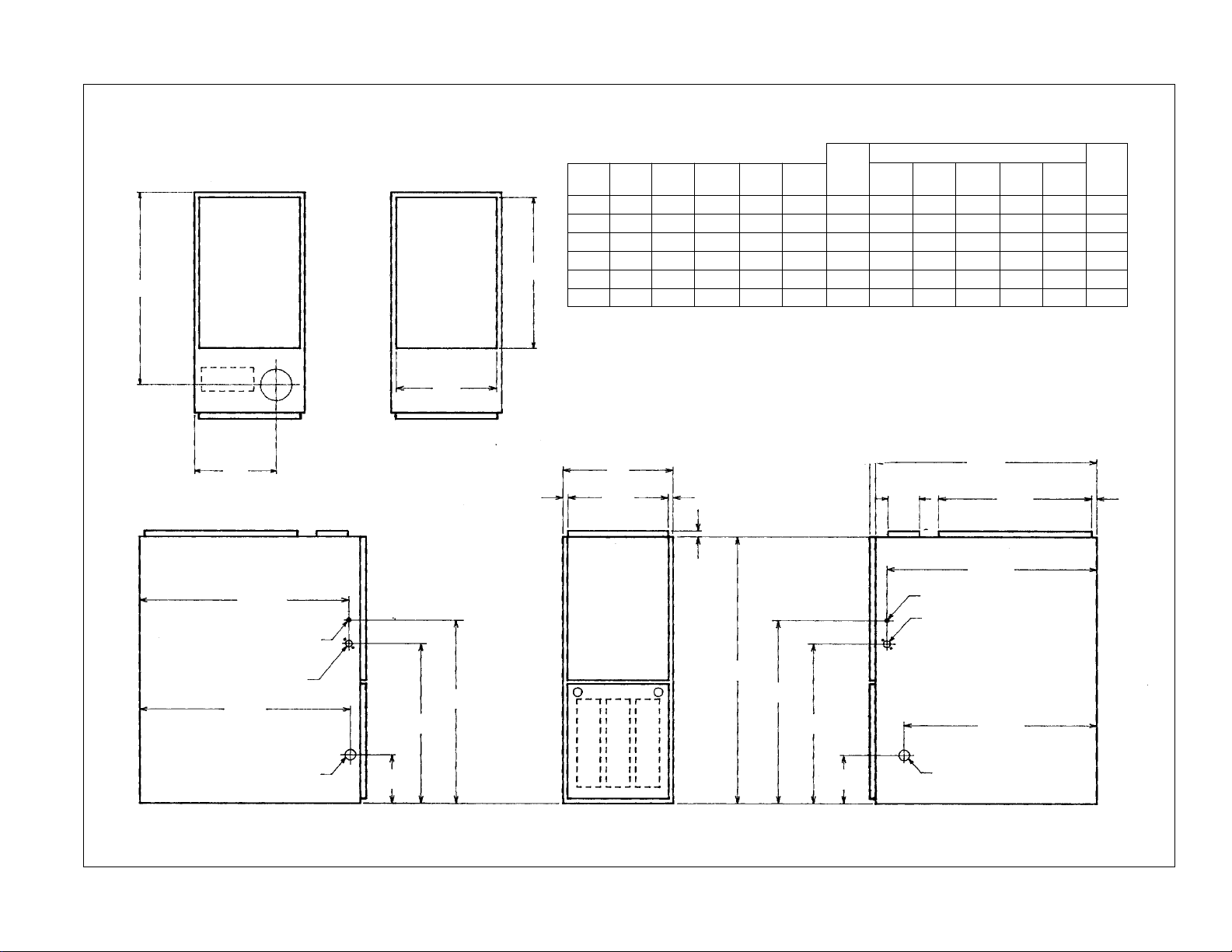
FIGURE 4
REDUCED CLEARANCE (IN.)
Model A B C D E
Left Right
Back Top Front Vent
Ship.
Side Side Wgts.
04, 05 14 12
27
⁄32 103⁄8 ➀ 111⁄2 0 4➁ 0 1 3 6➂ 85 lbs.
06, 07 17
1
⁄2 1611⁄32 121⁄8 ➀ 15 0 3➁ 0 1 3 6➂ 105 lbs.
10(A) 17
1
⁄2 1611⁄32 121⁄8 ➀ 15 0 3➁ 0 1 3 6➂ 115 lbs.
10(B) 21 19
27
⁄32 137⁄8 ➀ 181⁄2 0 0 0 1 3 6➂ 120 lbs.
12 24
1
⁄2 2311⁄32 155⁄8 ➀ 22 0 0 0 1 3 6➂ 140 lbs.
15 24
1
⁄2 2311⁄32 155⁄8 ➀ 22 0 0 0 1 3 6➂ 150 lbs.
CLEARANCE TO COMBUSTIBLE MATERIAL (INCHES)
HORIZONTAL “ONLY” MODELS
➀ May require 3( to 4( or 3( or 5( adapter.
➁ May be 0( with type B vent.
➂ May be 1( with type B vent.
TOP VIEW
FRONT
BOTTOM VIEW
LEFT END
RIGHT END
19
⁄32
D
B
A
C
28
1
⁄16
24
1
⁄2
26
13
⁄16
24
11
⁄32
23
17
⁄32
26
5
⁄8
14
3
⁄8
11
1
⁄2
11
1
⁄2
1
1
⁄4
14
3
⁄8
3
⁄4
19
⁄32
19
⁄32
24
11
⁄32
26
5
⁄8
24
7
⁄16
20
34
E
1
3
⁄8 DIA.
7
⁄8 DIA.
7
⁄8 DIA.
S.A.
GAS
CONNECTION
LOW
VOLTAGE
ELECTRICAL
CONNECTION
R.A.
IMPORTANT: This furnace is not approved or recommended for
installation on its back, with access doors facing upwards.
Page 8
CLEARANCE –
ACCESSIBILITY
The design of forced air furnaces with
input ratings as listed in the tables on
the following pages are certified by
A.G.A. Laboratories and CGA for the
clearances to combustible materials
shown in inches.
See name/rating plate and clearance
label for specific model number and
clearance information.
Service clearance of at least 24 inches
is recommended in front of all furnaces.
ACCESSIBILITY CLEARANCES,
WHERE GREATER, MUST TAKE
PRECEDENCE OVER FIRE
PROTECTION CLEARANCES.
UPFLOW AND HORIZONTAL
INSTALLATION — Certified for use on
combustible floor.
FURNACES MUST NOT BE
INSTALLED DIRECTLY ON
CARPETING, TILE OR OTHER
COMBUSTIBLE MATERIAL OTHER
THAN WOOD FLOORING.
INSTALLATION ON A
COMBUSTIBLE MATERIAL CAN
RESULT IN FIRE CAUSING
PROPERTY DAMAGE, SEVERE
PERSONAL INJURY OR DEATH.
UNIT DESIGN IS CERTIFIED FOR
INSTALLATION ON NONCOMBUSTIBLE FLOOR. A SPECIAL
COMBUSTIBLE FLOOR SUB-BASE
IS REQUIRED WHEN INSTALLING
ON A COMBUSTIBLE FLOOR.
FAILURE TO INSTALL THE SUBBASE MAY RESULT IN FIRE,
PROPERTY DAMAGE, PERSONAL
INJURY OR DEATH. THIS SPECIAL
BASE IS OFFERED AS AN
ACCESSORY FROM THE FACTORY.
SEE THE CLEARANCE LABEL
LOCATED INSIDE THE FURNACE
FOR THE APPROPRIATE MODEL
NUMBER.
THE SPECIAL BASE IS NOT
REQUIRED WHEN THE FURNACE IS
INSTALLED ON TOP OF AN AIR
CONDITIONING PLENUM.
A gas-fired furnace for installation in a
residential garage must be installed so
that the burner(s) and the ignition
source are located not less than 18(
above the floor and the furnace is
located or protected to avoid physical
damage by vehicles.
KEPT CLEAR AND FREE OF ALL
COMBUSTIBLE MATERIALS
INCLUDING GASOLINE AND OTHER
FLAMMABLE VAPORS AND
LIQUIDS. PLACEMENT OF
COMBUSTIBLE MATERIALS ON,
AGAINST OR AROUND THE
FURNACE JACKET CAN CAUSE AN
EXPLOSION OR FIRE RESULTING
IN PROPERTY DAMAGE,
PERSONAL INJURY OR DEATH.
THE HOMEOWNER SHOULD BE
CAUTIONED THAT THE FURNACE
AREA MUST NOT BE USED AS A
BROOM CLOSET OR FOR ANY
OTHER STORAGE PURPOSES.
DUCTING
Proper air flow is required for the
correct operation of this furnace. Too
little air flow can cause erratic
operation and can damage the heat
exchanger. The duct system must
carry the correct amount of air for
heating and cooling if summer air
conditioning is used.
Size the ducts according to acceptable
industry standards and methods. The
total static pressure drop of the entire
system should not exceed 0.5( w.c.
IMPORTANT: Some high efficiency
filters have a greater than normal
resistance to air flow. This can
adversely affect furnace operation. BE
SURE TO CHECK AIR FLOW if using
any filter other than the factoryprovided filter.
NEVER ALLOW PRODUCTS OF
COMBUSTION OR THE FLUE
PRODUCTS TO ENTER THE
RETURN AIR DUCTWORK, OR THE
CIRCULATING AIR SUPPLY. ALL
RETURN DUCTWORK MUST BE
ADEQUATELY SEALED AND
SECURED TO THE FURNACE WITH
SHEET METAL SCREWS, AND
JOINTS TAPED. WHEN A FURNACE
IS MOUNTED ON A PLATFORM,
WITH RETURN THROUGH THE
BOTTOM, IT MUST BE SEALED
AIRTIGHT BETWEEN THE FURNACE
AND THE RETURN AIR PLENUM.
THE RETURN AIR PLENUM MUST
BE PERMANENTLY ENCLOSED.
NEVER USE A DOOR AS A PART OF
THE RETURN AIR PLENUM. THE
FLOOR OR PLATFORM MUST
PROVIDE SOUND PHYSICAL
SUPPORT OF THE FURNACE,
WITHOUT SAGGING, CRACKS,
UPFLOW UNIT DESIGN REQUIRES
A SOLID METAL BASE PLATE (SEE
TABLE ON PAGE 8 OR FURNACE
CLEARANCE LABEL FOR PART
NUMBER) MUST BE IN PLACE
WHEN THE FURNACE IS
INSTALLED WITH SIDE OR REAR
AIR RETURN DUCTS. FAILURE TO
INSTALL A BASE PLATE COULD
CAUSE PRODUCTS OF
COMBUSTION TO BE CIRCULATED
INTO THE LIVING SPACE AND
CREATE POTENTIALLY
HAZARDOUS CONDITIONS,
INCLUDING CARBON MONOXIDE
POISONING.
When coils are used with air handlers
or furnaces and installed above a
finished ceiling or living area, it is
recommended that an auxiliary sheet
metal condensate drain pan be
fabricated and installed under entire
unit. Failure to do so can result in
property damage.
SITE SELECTION
1. Select a site in the building near the
center of the proposed, or existing,
duct system.
2. Give consideration to the vent
system piping when selecting the
furnace location. Be sure the venting
system can get from the furnace to
the termination with minimal length
and elbows.
3. Locate the furnace near the existing
gas piping. Or, if running a new gas
line, locate the furnace to minimize
the length and elbows in the gas
piping.
4. Locate the furnace to maintain
proper clearance to combustibles as
shown in the preceding tables.
COMBUSTIBLE MATERIAL MUST
NOT BE PLACED ON OR AGAINST
THE FURNACE JACKET OR WITHIN
THE SPECIFIED CLEARANCES OF
THE VENT PIPE. THE AREA
AROUND THE FURNACE MUST BE
8
CAUTION
!
WARNING
!
WARNING
!
WARNING
!
TABLE 1
FURNACE BASE BASE
WIDTH
PLATE NO. PLATE SIZE
14( RXGB-D14 11
5
⁄8( x 239⁄16(
17
1
⁄2( RXGB-D17 151⁄8( x 239⁄16(
21( RXGB-D21 18
5
⁄8( x 239⁄16(
24
1
⁄2( RXGB-D24 255⁄8( x 239⁄16(
Page 9
GAPS, ETC., AROUND THE BASE AS
TO PROVIDE A SEAL BETWEEN
THE SUPPORT AND THE BASE.
FAILURE TO PREVENT PRODUCTS
OF COMBUSTION FROM BEING
CIRCULATED INTO THE LIVING
SPACE CAN CREATE POTENTIALLY
HAZARDOUS CONDITIONS,
INCLUDING CARBON MONOXIDE
POISONING THAT COULD RESULT
IN PERSONAL INJURY OR DEATH.
DO NOT, UNDER ANY
CIRCUMSTANCES, CONNECT
RETURN OR SUPPLY DUCTWORK
TO OR FROM ANY OTHER HEAT
PRODUCING DEVICE SUCH AS A
FIREPLACE INSERT, STOVE, ETC.
DOING SO MAY RESULT IN FIRE,
CARBON MONOXIDE POISONING,
EXPLOSION, PERSONAL INJURY
OR PROPERTY DAMAGE.
BLOWER AND BURNERS MUST
NEVER BE OPERATED WITHOUT
THE BLOWER DOOR IN PLACE.
THIS IS TO PREVENT DRAWING
GAS FUMES (WHICH COULD
CONTAIN HAZARDOUS CARBON
MONOXIDE) INTO THE HOME THAT
COULD RESULT IN PERSONAL
INJURY OR DEATH.
UPFLOW UNITS
1. Position the unit to minimize long
runs or runs with many turns and
elbows.
2. Open the return air compartment.
a. If using side or back return air,
install the bottom base.
A SOLID METAL BASE PLATE, SEE
TABLE 1, OR FURNACE
CLEARANCE LABEL FOR PART
NUMBER MUST BE IN PLACE
WHEN THE FURNACE IS
INSTALLED WITH SIDE OR REAR
AIR RETURN DUCTS. FAILURE TO
INSTALL A BASE PLATE COULD
CAUSE PRODUCTS OF
COMBUSTION TO BE CIRCULATED
INTO THE LIVING SPACE AND
CREATE POTENTIALLY
HAZARDOUS CONDITIONS,
INCLUDING CARBON MONOXIDE
POISONING OR DEATH.
b. Cut an opening in the side or
back. The opening should be cut
the full width of the knockouts on
the unit.
NOTE: Where the maxiumum air flow
is 1800 CFM or more, both sides or the
bottom must be used for return air.
3. Connect the return duct or return air
cabinet to the unit. Make the
connection air tight to prevent
entraining combustion gases from
an adjacent fuel-burning appliance.
4. Be sure to have adequate space
for the unit filter.
NOTE: DO NOT take return air from
bathrooms, kitchens, furnace rooms,
garages, utility or laundry rooms, or
cold areas.
5. If summer air conditioning is desired,
position the indoor coil on the top of
the unit. Insure that no air can
bypass this coil.
6. Connect the supply air plenum to the
furnace plenum opening.
DOWNFLOW UNITS
1. Position the unit to minimize long
runs or runs with many turns and
elbows.
2. If summer air conditioning is desired,
position the indoor coil on the
bottom of the unit. Insure that no air
can bypass this coil.
3. If installing on a combustible floor
and not using an air conditioning
plenum, install the special
combustible floor base. See Figure 4.
THE DOWNFLOW FURNACE
DESIGN IS CERTIFIED FOR
INSTALLATION ON A NONCOMBUSTIBLE FLOOR. USE THE
SPECIAL BASE SPECIFIED ON THE
FURNACE CLEARANCE LABEL.
FAILURE TO INSTALL THE SPECIAL
BASE MAY RESULT IN FIRE,
PROPERTY DAMAGE, PERSONAL
INJURY OR DEATH. THIS SPECIAL
BASE IS SHIPPED FROM THE
FACTORY AS AN ACCESSORY.
4. Connect the furnace to the supply
air plenum.
5. Connect the return air ducting to the
return air opening at the top of the
unit. Make the connection air tight to
prevent entraining combustion
gases from an adjacent fuel-burning
appliance.
6. Be sure to have adequate space
for the unit filter.
NOTE: DO NOT take return air from
bathrooms, kitchens, furnace rooms,
garages, utility or laundry rooms, or
cold areas.
HORIZONTAL UNITS
1. Position the unit to minimize long
runs or runs with many turns and
elbows.
2. If summer air conditioning is desired,
position the indoor coil on the supply
air side of the unit. Insure that no air
can bypass this coil.
3. Connect the furnace to the supply
air plenum.
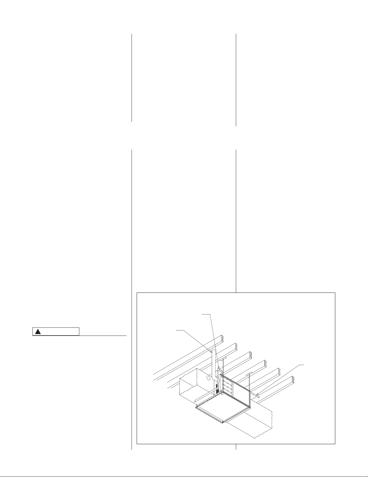
4. Secure the four angle brackets
shipped with the unit to the return air
opening. See Figure 6. Connect the
return air ducting to the return air
opening at the top of the unit. Make
the connection air tight to prevent
entraining combustion gases from
an adjacent fuel-burning appliance.
5. Be sure to have adequate space
for the unit filter.
NOTE: DO NOT take return air from
bathrooms, kitchens, furnace rooms,
garages, utility or laundry rooms, or
cold areas.
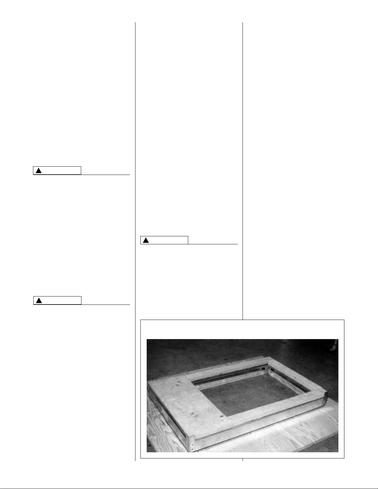
9
FIGURE 5
COMBUSTIBLE FLOOR BASE
WARNING
!
WARNING
!
WARNING
!
Page 10
10
THIS FURNACE AND ANY OTHER
FUEL-BURNING APPLIANCE MUST
BE PROVIDED WITH ENOUGH
FRESH AIR FOR PROPER
COMBUSTION AND VENTILATION
OF THE FLUE GASES. MOST
HOMES WILL REQUIRE THAT
OUTSIDE AIR BE SUPPLIED INTO
THE FURNACE AREA. FAILURE TO
DO SO CAN CAUSE DEATH FROM
CARBON MONOXIDE POISONING.
Adequate facilities for providing air for
combustion and ventilation must be
provided in accordance with section
5.3, Air for Combustion and
Ventilation, of the National Fuel Gas
Code, ANSI, Z223.1 latest edition or
CAN/CGA B149.1 and .2 or, applicable
provisions for the local building codes,
and not obstructed so as to prevent the
flow of air to the furnace.
OVERTEMPERATURE
SAFETY SWITCHES
This furnace is equipped with safety
switches in the control compartment to
protect against overtemperature
conditions caused by inadequate
combustion air supply. The switches
are located just above the burners on
the furnace center panel on upflow and
downflow models and also on each
side of the burners on
upflow/horizontal and horizontal “only”
models, and must be manually reset if
tripped. DO NOT jumper this switch. If
this switch should trip, a qualified
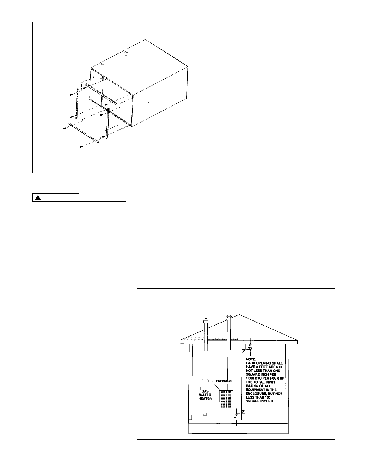
FIGURE 6
HORIZONTAL RETURN AIR DUCT
FIGURE 7
AIR FROM HEATED SPACE
furnace installer, service agency or the
gas supplier should be called to check
and/or correct for adequate combustion
air supply. If this unit is mounted in a
closet, the door must be closed when
making this check of the installation.
DO NOT reset the overtemperature
switch without taking corrective action
to assure that an adequate supply of
combustion air is maintained under all
conditions of operation.
Replace this switch only with the
identical replacement part.
IMPORTANT: Air for combustion and
ventilation must not come from a
corrosive atmosphere. Any failure due
to corrosive elements in the
atmosphere is excluded from warranty
coverage.
The following types of installation may
require OUTDOOR AIR for
combustion, due to chemical
exposures:
• Commercial buildings
• Buildings with indoor pools
• Furnaces installed in laundry rooms
• Furnaces in hobby or craft rooms
• Furnaces installed near chemical
storage areas.
Exposure to the following substances
in the combustion air supply may also
require OUTDOOR AIR for
combustion:
• Permanent wave solutions
• Chlorinated waxes and cleaners
• Chlorine-based swimming pool
chemicals
• Water softening chemicals
• De-icing salts or chemicals
• Carbon tetrachloride
• Halogen type refrigerants
• Cleaning solvents (such as
perchloroethylene)
• Printing inks, paint removers,
varnishes, etc.
• Hydrochloric acid
• Cements and glues
• Antistatic fabric softeners for clothes
dryers
• Masonry acid washing materials
COMBUSTION AND VENTILATION AIR
WARNING
!
FOUR ANGLE BRACKETS ARE SHIPPED WITH EACH
UNIT THAT CAN BE INSTALLED HORIZONTALLY. THESE
BRACKETS MAY BE USED TO SECURE THE RETURN
AIR DUCT TO A HORIZONTAL UNIT.
Page 11
Combustion air must be free of acid
forming chemicals; such as sulphur,
fluorine and chlorine. These elements
are found in aerosol sprays,
detergents, bleaches, cleaning
solvents, air fresheners, paint and
varnish removers, refrigerants and
many other commercial and household
products. Vapors from these products
when burned in a gas flame form acid
compounds. The acid compounds
increase the dew point temperature of
the flue products and are highly
corrosive after they condense.
ALL FURNACE INSTALLATIONS
MUST COMPLY WITH THE
NATIONAL FUEL GAS CODE AND
LOCAL CODES TO PROVIDE
ADEQUATE COMBUSTION AND
VENTILATION AIR FOR THE
FURNACE. FAILURE TO DO SO CAN
CREATE HAZARDOUS CONDITIONS
RESULTING IN PROPERTY
DAMAGE, BODILY INJURY OR
DEATH FROM SMOKE, FIRE OR
CARBON MONOXIDE.
Combustion air requirements are
determined by whether the furnace is
in an open (unconfined) area or in a
confined space such as a closet or
small room.
EXAMPLE 1.
FURNACE LOCATED IN AN
UNCONFINED SPACE
Using indoor air for combustion.
An unconfined space must have at
least 50 cubic feet for each 1,000 Btuh
of the total input for all appliances
in
the space. Here are a few examples of
the room sizes required for different
inputs. The sizes are based on 8 foot
ceilings.
Btuh Minimum Sq. Feet Typical Room Size
Input With 8' Ceiling With 8' Ceiling
45,000 281 12*x24* or 16*x18*
50,000 312 14*x24* or 18*x18*
67,500 421 15*x28* or 20*x21*
75,000 469 15*x31* or 20*x24*
100,000 625 20*x31* or 25*x25*
125,000 833 23*x34* or 26*x30*
150,000 938 25*x38* or 30*x31*
If the open space containing the
furnace is in a building with tight
construction (contemporary
construction), outside air may still be
required for the furnace to operate and
vent properly. Outside air openings
should be sized the same as for a
confined space.
11
WARNING
!
FIGURE 8
AIR FROM ATTIC/CRAWL SPACE
EXAMPLE 2.
FURNACE LOCATED IN A
CONFINED SPACE
A confined space (any space smaller
than shown above as “unconfined”)
must have openings into the space
which are located in accordance with
the requirements set forth in the
following subsections A and B. Size the
openings by how they are connected to
the heated area or to the outside, and
by the input of all appliances in the
space.
If confined space is within a building
with tight construction, combustion air
must be taken from outdoors or area
freely communicating with the
outdoors.
A. USING INDOOR AIR FOR
COMBUSTION
IMPORTANT: Air should not be taken
from a heated space with a fireplace,
exhaust fan or other device that may
produce a negative pressure.
If combustion air is taken from the
heated area, the openings must
each
have at least 100 square
inches of free area. Each opening
must have at least one square inch
of free area for each 1,000 Btuh of
total input in the space. Here are
some examples of typical openings
required.
Btuh Free Area
Input Each Opening
45,000 100 Square Inches
100,000 100 Square Inches
150,000 150 Square Inches
B. USING OUTDOOR AIR FOR
COMBUSTION
IMPORTANT: NEVER TAKE
COMBUSTION AIR FROM AN
ATTIC SPACE THAT IS
EQUIPPED WITH POWER
VENTILATION.
The confined space must
communicate with the outdoors
according to Methods 1 and 2. The
minimum air opening dimension
shall not be less than 3 inches.
When using ducts, they shall be of
the same cross-sectional area as
the free area of the openings to
which they connect.
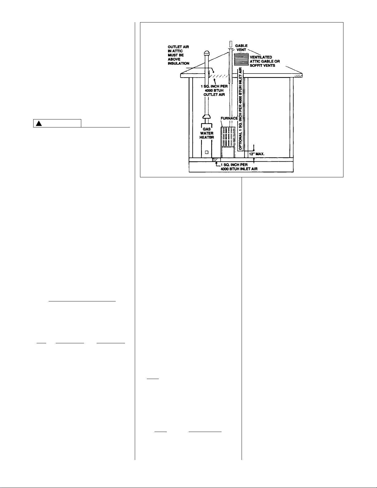
Method 1
Provide two permanent openings,
one located within 12 inches of the
top and one located within 12 inches
of the bottom of the enclosure. Each
opening shall communicate directly,
or by ducts, with the outdoors or
spaces (crawl or attic) that freely
communicate with the outdoors.
a. Where directly communicating
with the outdoors or where
communicating to the outdoors
through VERTICAL DUCTS, each
opening shall have a minimum
free area of 1 square inch for
each 4000 BTUH of total
appliance input rating in the
enclosure. Here are typical duct
sizes.
Page 12
a. One square inch for each 3000
BTUH of the total input rating of all
equipment located in the enclosure,
AND
b. Not less than the sum of the areas
of all vent connectors in the confined
space.
IMPORTANT: IF THE FURNACE IS IN
A LOCATION WITH AN EXHAUST
FAN, THERE MUST BE SUFFICIENT
VENTILATION TO PREVENT THE
EXHAUST FAN FROM CREATING A
NEGATIVE PRESSURE IN THE
ROOM.
Combustion air openings must NOT
BE RESTRICTED in any manner.
CONSULT LOCAL CODES FOR
SPECIAL REQUIREMENTS.
Air opening in the furnace casing front,
return air grilles, and warmm air
registers must not be obstructed.
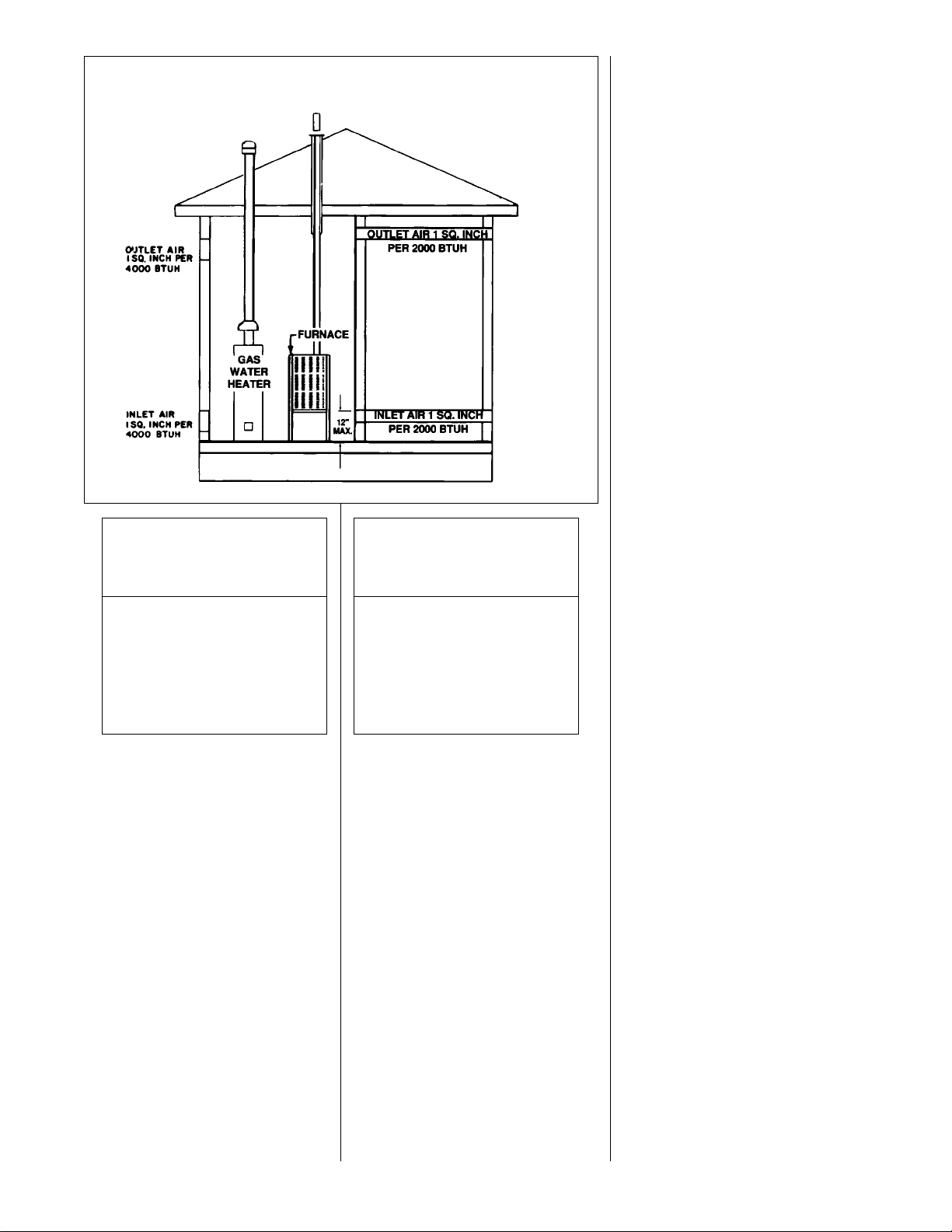
b. Where communicating with
outdoors through HORIZONTAL
DUCTS, each opening shall have
a minimum free area of 1 square
inch for each 2000 BTUH of
total input rating for all equipment
in the enclosure. Here are typical
duct sizes.
12
FIGURE 9
OUTSIDE AIR USING A HORIZONTAL INLET & OUTLET
Method 2
One permanent opening, located within
12 inches of the top of the enclosure,
shall be permitted where the
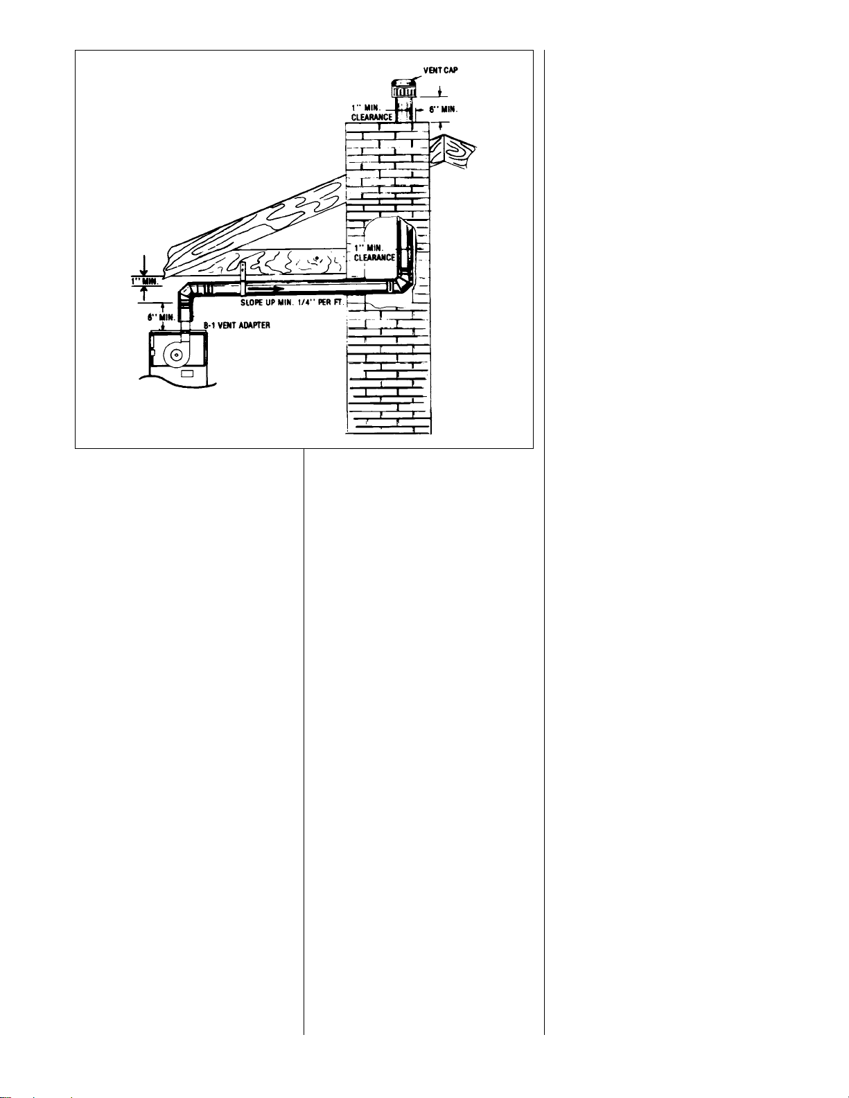
equipment has clearances of at least 1
inch from the sides and back and 6
inches from the front of the appliance.
The opening shall directly
communicate with the outdoors or
communicate through a vertical or
horizontal duct to the outdoors or
spaces (crawl or attic) that freely
communicate with the outdoors and
have a minimum free area of:
VERTICAL OUTDOOR AIR
OPENING DIMENSIONS
BTUH Free Area Round
Input Each Opening Pipe Size
45,000 11.25 sq. inches 4(
50,000 12.50 sq. inches 4(
67,500 16.90 sq. inches 5(
75,000 18.75 sq. inches 5(
100,000 25.00 sq. inches 6(
125,000 31.25 sq. inches 7(
150,000 37.50 sq. inches 7(
HORIZONTAL OUTDOOR AIR
OPENING DIMENSIONS
BTUH Free Area Round
Input Each Opening Pipe Size
45,000 22.50 sq. inches 6(
50,000 25.00 sq. inches 6(
67,500 33.75 sq. inches 7(
75,000 37.50 sq. inches 7(
100,000 50.00 sq. inches 8(
125,000 62.50 sq. inches 9(
150,000 75.00 sq. inches 10(
Page 13
GENERAL INFORMATION
The furnace must be vented in
accordance with these instructions,
National Fuel Gas Code, ANSI Z223.1
and/or the Natural Gas Installation
Code, CAN/CGA-B149.1 & .2 and
requirements or codes of the local utility
or other authority having jurisdiction.
DEVICES ATTACHED TO THE FLUE
OR VENT FOR THE PURPOSE OF
REDUCING HEAT LOSS UP THE
CHIMNEY HAVE NOT BEEN TESTED
AND HAVE NOT BEEN INCLUDED IN
THE DESIGN CERTIFICATION OF
THIS FURNACE. WE, THE
MANUFACTURER, CANNOT AND
WILL NOT BE RESPONSIBLE FOR
INJURY OR DAMAGE CAUSED BY
THE USE OF SUCH UNTESTED
AND/OR UNCERTIFIED DEVICES,
ACCESSORIES OR COMPONENTS.
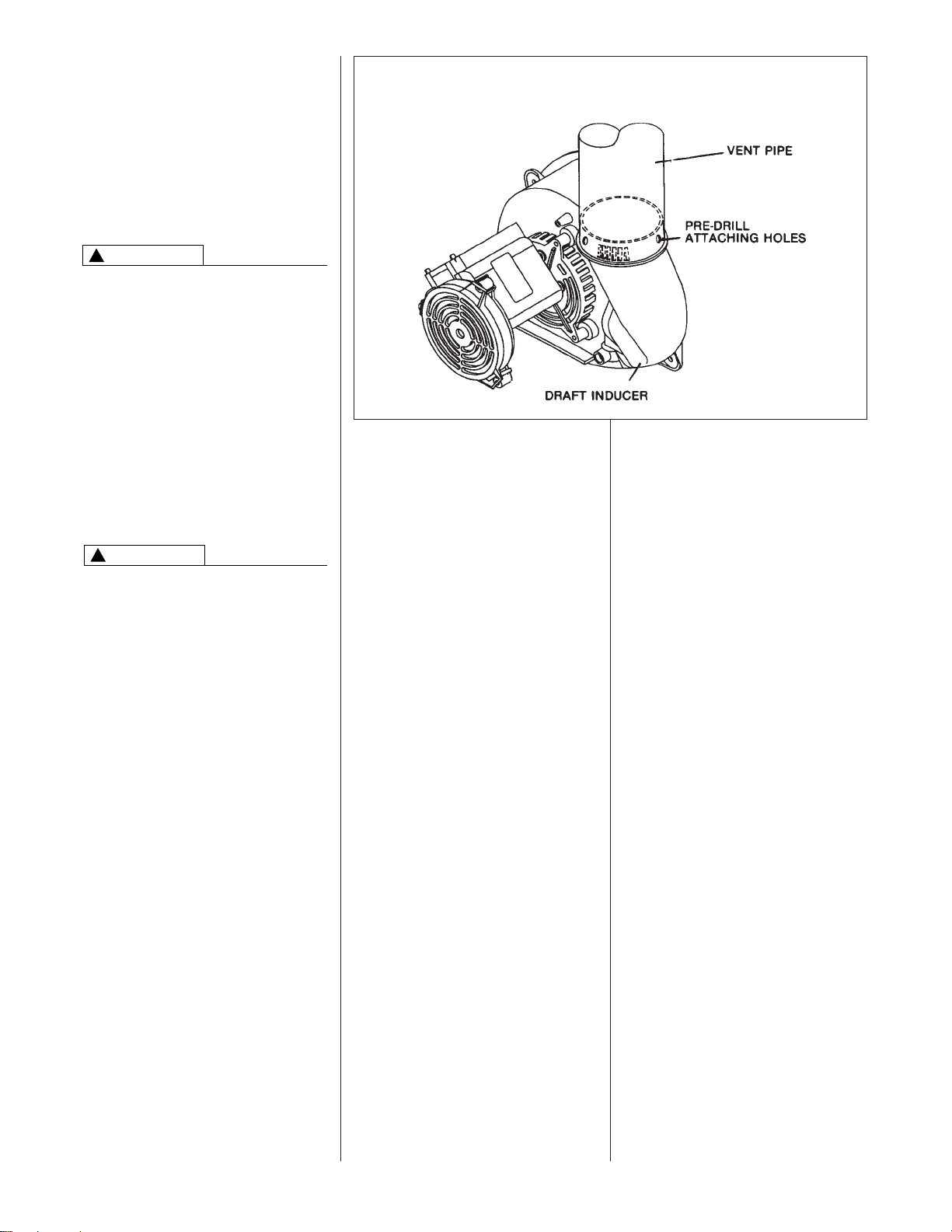
DRAFT INDUCER
VENT PIPE ATTACHING HOLES
MUST BE PREDRILLED IN THE
DRAFT INDUCER COLLAR TO
PREVENT PLASTIC MATERIAL
FROM CRACKING. DRILL 1/8(
DIAMETER HOLES THROUGH THE
VENT PIPE AND COLLAR AND USE
#8 SCREWS TO ATTACH. SEE
FIGURE 10. FAILURE TO FOLLOW
THIS WARNING CAN CAUSE
RECIRCULATION OF FLUE
PRODUCTS CAUSING CARBON
MONOXIDE POISONING
RESULTING IN PERSONAL INJURY
OR DEATH.
IMPORTANT APPLICATION
NOTES
When the furnace is used as a
replacement, the existing vent system
should be inspected to assure that
there are no obstructions, blockage, or
any signs of corrosion.
NOTE: WHEN THE VENT TABLE
PERMITS MORE THAN ONE
DIAMETER OF PIPE FOR A
CONNECTOR OR VENT, THE
SMALLEST PERMITTED DIAMETER
MUST BE USED,
VENT PIPE MAY BE TYPE “B-1,”
EITHER RIGID OR SUITABLE
FLEXIBLE CONSTRUCTION THAT
CARRIES A U.L. LISTING.
COMMON VENTING IS ALLOWED
WITH VERTICAL B-1 VENT
SYSTEMS, AND LINED MASONRY
CHIMNEYS. FOLLOW THE
NATIONAL FUEL GAS CODE, ANSI
Z223.1 AND/OR THE NATURAL GAS
INSTALLATION CODE, CAN/CGAB149.1 & .2 FOR PROPER
INSTALLATION PRACTICES.
SINGLE WALL VENT CONNECTORS
TO “B-1 VENT OR MASONRY
CHIMNEYS” MAY BE USED UNDER
THE GUIDELINES OF THE
NATIONAL FUEL GAS CODE, ANSI
Z223.1 AND/OR THE NATURAL GAS
INSTALLATION CODE, CAN/CGAB149.1 & .2.
The entire length of the vent
connector shall be readily
accessible for inspection, cleaning
and replacement.
13
WARNING
!
WARNING
!
FURNACE CATEGORY
INFORMATION
This furnace is shipped as a Category I
type induced draft furnace. A Category
I furnace operates with a nonpositive
vent pressure and has a vent gas
temperature at least 140°F above the
dew point of the vent gases. A
Category I type may be a draft hood
equipped furnace or have a fan
assisted combustion system (induced
draft). The inducer is used to pull flue
products through the combustion
chamber and as they leave the
furnace, most of the energy has been
dissipated. The buoyant effect of the
flue gases provides venting to the
outdoors.
During the off cycle, the inducer is off
and there is very little flow through the
vent, cooling the vent. During the on
cycle there is no dilution airflow, as
with a draft hood type furnace.
Although the vent heats up rapidly
without dilution air, the flue products
contain more water vapor, which
results in a higher dew point
temperature. It is most important that
you follow the guidelines in these
instructions to prevent the possible
formation of condensation in the
venting system.
As a Category I furnace it may be
vented vertically with type B-1 vent
pipe and also may be common vented,
as described in these instructions.
FIGURE 10
ATTACHING TO DRAFT INDUCER COLLAR
VENTING
Page 14
14
“B-1” VERTICAL VENTING
Type “B-1” vents must be installed in
accordance with the terms of their
listings and the vent manufacturer’s
instructions.
“B-1” vents must be supported and
spaced in accordance with their listings
and the manufacturer’s instructions. All
vents must be supported to maintain
their minimum clearances from
combustible material.
VERTICAL VENTING
Categorized
Furnace Vent
Input Size Required
45K 3(
50K 3(
67K *4(
75K *4(
100K *4(
125K *4(
150K *5(
*NOTE: All furnaces have a 3( vent
connection as shipped from the factory. A 3(
to 4( or 3( to 5( vent transition is required on
all but the 45,000 and 50,000 BTUH models
when vertically vented or common vented
with metal vent pipes. THE VENT
TRANSITION CONNECTION MUST BE
MADE AT THE FURNACE VENT EXIT. It
must originate with an adapter if required, at
the furnace flue collar and terminate either
in a listed cap or roof assembly. When
common venting, the vent connector size
may differ from the above diameters
depending on application. See ANSI
Z21.47-1993/CAN/CGA-2.3-M93 or latest
edition tables.
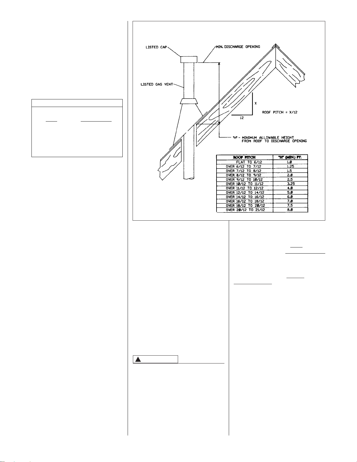
VERTICAL VENT SYSTEMS:
1. A gas vent shall terminate above the
roof surface with a listed cap or
listed roof assembly. Gas vents 12
inches in size or smaller with listed
caps shall be permitted to be
terminated in accordance with
Figure 11, provided they are at least
8 feet from a vertical wall or similar
obstruction. All other gas vents shall
terminate not less than 2 feet above
the highest point where they pass
through the roof and at least 2 feet
higher than any portion of a building
within 10 feet.
2. A type B gas vent shall terminate at
least 5 feet in vertical height above
the highest connected equipment
draft hood or flue collar.
3. Must rise
1
⁄4( per foot away from the
furnace on horizontal runs and be
supported with straps or hangers so
it has no sags or dips. Supports at 4
foot intervals and at all elbows are
recommended.
4. The vent connector must be
mechanically fastened to the outlet
collar of the furnace with at least (2)
SPECIAL VENT SYSTEMS (SVS)
IMPORTANT: IT IS RHEEM’S
POSITION NOW THAT NEW
INSTALLATIONS OF ANY HTPV PIPE
USED IN A CATEGORY III VENT
APPLICATION, INCLUDING
SELKIRK’S SELVENT™ II HTPV
PRODUCT, SHOULD CEASE
IMMEDIATELY.
POWER VENT SYSTEMS
When vertical venting is not possible,
the only acceptable method for
horizontal venting is with the use of
Tjernlund model GPAK-1TR or Field
Controls models SWG-4R power
venter. Type B vent pipe and fittings
must be used. Common venting is not
permitted
All application and installation
instructions supplied with the power
venter must be followed.
Please address all questions regarding
power venter installation, agency
listings and furnace model compatibility
to:
Tjernlund Products, Inc.
(800) 255-4208 or (612) 426-2993
Field Controls L.L.C.
(800) 742-8368 or (919) 522-0214
sheet metal screws except vent
connectors that are B-1 material.
These shall be assembled in
accordance with the manufacturer’s
instructions. See Figure 9.
NOTE: Refer to the National Fuel Gas
Code, ANSI Z223.1 and/or the Natural
Gas Installation Code, CAN/CGAB149.1 & .2.
Single appliance venting of a fan
assisted furnace into a tile-lined
masonry chimney is prohibited. The
chimney must be lined with either Type
B vent or with a listed, single wall,
metal lining system. Reference
National Fuel Gas Code, ANSI Z223.1
and/or the Natural Gas Installation
Code, CAN/CGA-B149.1 & .2. See
Figure 11 for typical B-1 vent chase.
DO NOT CONNECT THIS FURNACE
TO A CHIMNEY USED TO VENT A
SOLID FUEL APPLIANCE (WOOD OR
COAL). VENTING WITH A SOLID
FUEL APPLIANCE CAN LEAD TO
IMPROPER FUNCTIONING OF THE
UNIT, AND DUE TO SOOTING, THE
POSSIBILITY OF FIRE RESULTING
IN PROPERTY DAMAGE,
PERSONAL INJURY OR DEATH.
FIGURE 11
TYPICAL VENTING WITH “B-1” VENT
WARNING
!
Page 15
3. Insofar as is practical, close all
building doors, windows and all
doors between the space where the
appliances remaining connected to
the common venting system are
located. Turn on clothes dryers and
any appliance not connected to the
common venting system. Turn on
any exhaust fans, such as range
hoods and bathroom exhausts, so
they will operate at maximum speed.
Do not operate a summer exhaust
fan. Close fireplace dampers.
4. Follow the lighting instructions.
Place the appliance being inspected
into operation. Adjust the thermostat
so the appliance will operate
continuously.
5. Test for spillage at the draft hood
relief opening after 5 minutes of
main burner operation. Use the
flame of a match or candle, or
smoke from a cigarette, cigar, or
pipe.
EXISTING VENT SYSTEMS
IMPORTANT RETROFIT
VENTING INSTRUCTIONS
If this furnace is a replacement
installation, ALWAYS INSPECT the
existing vent system to be sure there
are no obstructions, blockages, or
signs of corrosion.
When the existing furnace is removed
from a venting system serving other
appliances, the venting is likely to be
too large to properly vent the
remaining attached appliances.
The following steps shall be followed
with each appliance that remains
connected to the common venting
system, while the other appliances that
remain connected to the common
venting systems are not in operation.
NOTE: WHEN THE VENT TABLE
PERMITS MORE THAN ONE
DIAMETER OF PIPE FOR A
CONNECTOR OR VENT, THE
SMALLEST PERMITTED DIAMETER
MUST BE USED.
1. Seal any unused openings in the
common venting system.
2. Visually inspect the venting system
for proper size and horizontal pitch
and determine that there is no
blockage, restriction, leakage,
corrosion or other deficiencies which
could cause an unsafe condition.
15
FIGURE 12
DEDICATED VENTING THROUGH
CHIMNEY WITH “B-1” VENT
6. After it has been determined that
each appliance that remains
connected to the common venting
system properly vents (when tested
as outlined above) return doors,
windows, exhaust fans, fireplace
dampers and any other gas-burning
appliance to their previous
conditions of use.
7. If improper venting is observed
during any of the above tests, the
common venting system must be
resized. Refer to National Fuel Gas
Code, ANSI Z223.1 and/or the
Natural Gas Installation Code,
CAN/CGA-B149.1 & .2.
Page 16

FIGURE 13
GAS PIPING INSTALLATION
UPFLOW & DOWNFLOW
16
GAS SUPPLY AND PIPING
GAS SUPPLY
THIS FURNACE IS EQUIPPED AT
THE FACTORY FOR USE ON
NATURAL GAS ONLY. CONVERSION TO LP GAS REQUIRES A
SPECIAL KIT SUPPLIED BY THE
DISTRIBUTOR OR MANUFACTURER. MAILING ADDRESSES
ARE LISTED ON THE FURNACE
RATING PLATE, PARTS LIST AND
WARRANTY. FAILURE TO USE
THE PROPER CONVERSION KIT
CAN CAUSE FIRE, CARBON
MONOXIDE POISONING,
EXPLOSION, PROPERTY
DAMAGE, PERSONAL INJURY OR
DEATH.
See the conversion kit index
supplied with the furnace. This
index identifies the proper LP Gas
Conversion Kit required for each
particular furnace.
IMPORTANT: Any additions,
changes or conversions required for
the furnace to satisfactorily meet the
application should be made by a
qualified installer, service agency or
the gas supplier, using factoryspecified or approved parts.
IMPORTANT: Connect this furnace
only to gas supplied by a commercial
utility.
IMPORTANT: A U.L. recognized
fuel gas and CO detector(s) are
recommended in all applications,
and their installation should be in
accordance with the detector
manufacturer’s recommendations
and/or local laws, rules, regulations or
customs.
GAS PIPING
Install the gas piping according to all
local codes and regulations of the
utility company.
If possible, run a separate gas supply
line directly from the meter to the
furnace. Consult the local gas
company for the location of the
manual main shut-off valve. The gas
line and manual gas valve must be
adequate in size to prevent undue
pressure drop and never smaller
than the pipe size to the combination gas valve on the furnace.
Refer to Table 2 for the recommended pipe size for natural gas and
Table 3 for LP gas pipe sizes.
!
WARNING
HORIZONTAL
IMPORTANT: It is permissible to run
flexible gas connector inside the unit to
a piece of black pipe.
Install a ground joint union inside the
cabinet to easily remove the control
valve assembly. Install a manual
shut-off valve in the gas line outside
the furnace casing. The valve should
be readily accessible to turn the gas
supply on or off. Install a drip leg in the
gas supply line as close to the furnace
as possible. Always use a pipe
compound resistant to the action of
liquefied petroleum gases on all
threaded connections.
IMPORTANT: When making gas pipe
connections, use a back-up wrench to
prevent any twisting of the control
assembly and gas valve.
Any strains on the gas valve can
change the position of the gas orifices
in the burners. This can cause erratic
furnace operation.
IMPORTANT: ENSURE that the
furnace gas control valve not be
subjected to high gas line supply
pressures.
DISCONNECT the furnace and its
individual shut-off valve from the gas
supply piping during any pressure
testing that exceeds 1/2 p.s.i.g. (3.48
kPa).
Page 17

17
GAS PRESSURE
Natural gas supply pressure should
be 5" to 7
( w.c. LP gas supply
pressure should be 11( to 14( w.c.
This pressure must be maintained
with all other gas-fired appliances in
operation. Never exceed a maximum
gas supply pressure of 14( w.c. with
any fuel.
The minimum supply pressure to the
gas valve for proper furnace input
adjustments is 5( w.c. for natural gas,
however 6( to 7( is recommended. The
minimum supply pressure is 11( w.c.
for LP gas.
NEVER PURGE A GAS LINE INTO
THE COMBUSTION CHAMBER.
NEVER USE MATCHES, FLAME OR
ANY IGNITION SOURCE FOR
CHECKING LEAKAGE. FAILURE TO
FOLLOW THIS WARNING CAN
CAUSE AN EXPLOSION OR FIRE
RESULTING IN PROPERTY
DAMAGE, PERSONAL INJURY OR
DEATH.
To check for gas leakage, use an
approved chloride-free soap and water
solution, an electronic combustible gas
detector (see Figure 14), or other
approved method.
!
WARNING
FIGURE 14
ELECTRONIC COMBUSTIBLE
GAS DETECTOR
FIGURE 15
LP KIT CONTENTS
FIGURE 16
HOSE CONNECTION TO LINE PRESSURE TAP
Page 18

LP CONVERSION
The valve can be converted to use
liquefied petroleum (LP) gas by
replacing the pressure regulator spring
with the conversion kit spring. This LP
kit spring allows the regulator to
maintain the proper manifold pressure
for LP gas. The correct burner LP
orifices are included in
the kit. See Figure 14.
NOTE: Order the correct LP conversion
kit from the furnace manufacturer.
Furnace conversion to LP gas must
be performed by a qualified
technician.
To change orifice spuds for either
conversion to LP or for elevation:
1. Shut off the manual main gas
valve and remove the gas
manifold.
2. Replace the orifice spuds.
3. Reassemble in reverse order.
Consult the tables at right if there is any
question concerning orifice sizing.
4. Turn the gas supply back on and
check for proper operation and
manifold pressure.
5. Attach the notice label alerting the
next service technician that the
furnace has been converted to LP
gas.
NOx MODELS
When converting furnaces equipped
with NOx inserts to LP gas, remove the
NOx insert assemblies. Steps for
removal are listed below:
1. Turn off all electrical power and the
gas supply to the furnace.
2. Remove the burner door from the
furnace.
3. Remove the igniter assembly –
handle with care.
4. Remove the two screws attaching
the NOx insert retainer brackets to
the center panel. Pull the retainer
rod.
5. Put the two screws back into the
holes in the center panel.
6. Re-install the igniter and burner
assemblies.
7. Replace burner door.
8. Turn on electrical power and gas
supply to the unit.
18
RATING PLATE ELEVATION
INPUT
BTU/HR 0 TO 7,999 FT. 8,000 FT. AND ABOVE
NATURAL GAS
HEATING VALUE @ 1,000 BTU/FT
3
, SPECIFIC GRAVITY 0.62
MANIFOLD PRESSURE @ 3.5( W.C.
45,000 43 45
50,000 42 43
67,500 43 45
75,000 42 43
100,000 42 43
125,000 42 43
150,000 42 43
L.P. GAS
HEATING VALUE @ 2,475 BTU/FT
3
, SPECIFIC GRAVITY 1.52/
MANIFOLD PRESSURE @ 10( W.C.
45,000 54 55
50,000 54 55
67,500 54 55
75,000 54 55
100,000 54 55
125,000 54 55
150,000 54 55
ORIFICE SIZING CHART
RATING PLATE ELEVATION
INPUT
BTU/HR 0 TO 1,999 FT. 2,000 FT. TO 4,500 FT.
NATURAL GAS
HEATING VALUE @ 1,000 BTU/FT
3
, SPECIFIC GRAVITY 0.62
MANIFOLD PRESSURE @ 3.5( W.C.
45,000 43 45
50,000 42 43
67,500 43 45
75,000 42 43
100,000 42 43
125,000 42 43
150,000 42 43
L.P. GAS
HEATING VALUE @ 2,475 BTU/FT
3
, SPECIFIC GRAVITY 1.52/
MANIFOLD PRESSURE @ 10( W.C.
45,000 54 55
50,000 54 55
67,500 54 55
75,000 54 55
100,000 54 55
125,000 54 55
150,000 54 55
ORIFICE SIZING CHART (CANADA)
Page 19

TABLE 2
NATURAL GAS PIPE CAPACITY TABLE (CU. FT./HR.)
Capacity of gas pipe of different diameters and lengths in cu. ft. per hr. with pressure drop of 0.3 in. and specific
gravity of 0.60 (natural gas).
Nominal Length of Pipe, Feet
Iron Pipe
Size, Inches 10 20 30 40 50 60 70 80
1/2 132 92 73 63 56 50 46 43
3/4 278 190 152 130 115 105 96 90
1 520 350 285 245 215 195 180 170
1-1/4 1,050 730 590 500 440 400 370 350
1-1/2 1,600 1,100 890 760 670 610 560 530
After the length of pipe has been determined, select the pipe size which will provide the minimum cubic feet per hour
required for the gas input rating of the furnace. By formula:
Gas Input of Furnace (BTU/HR)
Cu. Ft. Per Hr. Required =
Heating Value of Gas (BTU/FT3)
The gas input of the furnace is marked on the furnace rating plate. The heating value of the gas (BTU/FT3) may be
determined by consulting the local natural gas utility or the LP gas supplier.
TABLE 3
LP GAS PIPE CAPACITY TABLE (CU. FT./HR.)
Maximum capacity of pipe in thousands of BTU per hour of undiluted liquefied petroleum gases (at 11 inches
water column inlet pressure).
(Based on a Pressure Drop of 0.5 Inch Water Column)
Nominal Length of Pipe, Feet
Iron Pipe
Size, Inches 10 20 30 40 50 60 70 80 90 100 125 150
1/2 275 189 152 129 114 103 96 89 83 78 69 63
3/4 567 393 315 267 237 217 196 182 173 162 146 132
1 1,071 732 590 504 448 409 378 346 322 307 275 252
1-1/4 2,205 1,496 1,212 1,039 913 834 771 724 677 630 567 511
1-1/2 3,307 2,299 1,858 1,559 1,417 1,275 1,181 1,086 1,023 976 866 787
2 6,221 4,331 3,465 2,992 2,646 2,394 2,205 2,047 1,921 1,811 1,606 1,496
Example (LP): Input BTU requirement of unit, 150,000
Equivalent length of pipe, 60 ft. = 3/4" IPS required.
19
SETTING GAS PRESSURE
The maximum gas supply pressure
to the furnace should be 7( w.c.
natural gas, or 14( w.c. LP gas. The
minimum supply gas pressure to the
gas valve should be 5" w.c. natural gas
or 11" w.c. LP gas. A properly
calibrated U-Tube manometer is
required for accurate gas pressure
measurements.
Supply Gas Pressure Measurement.
A line pressure tap is on the input side
of the gas valve.
1. With gas shut off to the furnace at
the manual gas valve outside the
unit, remove the input pressure tap
plug.
2. Connect a U-Tube manometer to
the pressure tap. See Figure 15.
3. Turn on the gas supply and
operate the furnace and all other
gas-fired units on the same gas
line as the furnace.
4. Note or adjust the line gas
pressure to give:
A. 5( - 7( w.c. for natural gas.
B. 11( - 14( w.c. for LP gas.
5. Shut off the gas at the manual gas
valve and remove the
U-Tube manometer.
6. Replace the pressure tap plug
before turning on the gas.
If the supply gas line pressure is above
these ranges, install an in-line gas
regulator to the furnace for natural gas
units. With LP gas, have the LP
supplier reduce the line pressure at the
regulator.
If supply gas line pressure is below
these ranges, either remove any
restrictions in the gas supply piping or
enlarge the gas pipe. See Tables 2 and
3. With LP gas, have the LP supplier
adjust the line pressure at the
regulator.
Page 20

20
TURN OFF ELECTRIC POWER AT
THE FUSE BOX OR SERVICE PANEL
BEFORE MAKING ANY
ELECTRICAL CONNECTIONS.
ALSO, THE GROUND CONNECTION
MUST BE COMPLETED BEFORE
MAKING LINE VOLTAGE
CONNECTIONS. FAILURE TO DO
SO CAN RESULT IN ELECTRICAL
SHOCK, SEVERE PERSONAL
INJURY OR DEATH.
IMPORTANT: THE FURNACE MUST
BE INSTALLED SO THAT THE
ELECTRICAL COMPONENTS ARE
PROTECTED FROM WATER
(FURNACE CONDENSATE).
ELECTRICAL CONNECTIONS
THE CABINET MUST BE
PERMANENTLY GROUNDED. A
GROUND SCREW IS PROVIDED IN
THE JUNCTION BOX FOR THIS
PURPOSE. FAILURE TO DO SO CAN
RESULT IN FIRE, ELECTRICAL
SHOCK, PERSONAL INJURY OR
DEATH.
The electrical supply requirements are
listed on the furnace rating plate.
Use a separate fused branch electrical
circuit containing a properly sized fuse
or circuit breaker. Run this circuit
directly from the main switch box to an
electrical disconnect which must be
readily accessible and located within
sight of the furnace. Connect from the
disconnect to the junction box on the
left side of the furnace, inside the
control compartment. See appropriate
wiring diagram.
NOTE: The electrical junction box
inside the furnace control compartment
may be relocated to the right side if
necessary. A knockout is provided.
NOTE: L1 (hot) and L2 (neutral)
polarity must be observed when
making field connections to the
furnace. The ignition control on electric
ignition models will not sense flame if
L1 and L2 are reversed.
Installation of the electric supply line
should be in accordance with the
National Electric Code ANSI/NFPA No.
70, latest edition, or Canadian
Electrical Code Part 1 - CSA Standard
C22.1 and local building codes.
This can be obtained from:
National Fire Protection Association
Batterymarch Park
Quincy, MA 02269
Canadian Standards Association
178 Rexdale Blvd.
Etobicoke (Toronto), Ontario
Canada M9W, 1R3
WARNING
!
WARNING
!
ELECTRICAL WIRING
as shown on the wiring diagram. Never
install the thermostat on an outside
wall or where it will be influenced by
drafts, concealed hot or cold water
pipes, lighting fixtures, radiation from
fireplace, rays of sun, lamps, television,
radios or air streams from registers.
Refer to the instructions packed with
the thermostat for best anticipator
adjustment or selection or see below.
HEAT ANTICIPATOR SETTINGS
For adjusting the thermostat heat
anticipator setting; (a) add the current
draw of the various components in the
system or (b) measure the current flow
on either the R or W thermostat circuit
and set the thermostat heat anticipator
according to the current flow
measured.
The room thermostat must be
compatible with the integrated furnace
control on the furnace. All thermostats
available from the furnace
manufacturer’s Parts Department are
acceptable. Generally, all thermostats
that are not of the “current robbing”
type are compatible with the integrated
furnace control we use.
NOTICE: An isolation relay can be
added to prevent any compatibility
problems that may occur. Use a singlepole, single-throw relay with a 24-volt
AC coil. The contacts should be rated
for .5 amps minimum at 24 volts. See
Figure 17.
Install the room thermostat in
accordance with the instruction sheet
in the box with the thermostat. Run the
thermostat lead wires inside the control
compartment. Connect the thermostat
THERMOSTAT
FIELD WIRE SIZE FOR 24 VOLT THERMOSTAT CIRCUITS
SOLID COPPER WIRE - AWG.
3.0
2.5
2.0
16
16
18
14
14
16
12
12
14
10
12
12
10
12
12
10
10
10
50 100 150 200 250 300
Length of Run – Feet (1)
Thermostat Load - Amps
① The total wire length is the distance from the furnace to the
thermostat and back to the furnace.
NOTE: Do not use 24 volt control wiring smaller than No. 18.
FIGURE 17
ISOLATION RELAY
ST-A0804-01
Page 21

21
FIELD INSTALLED OPTION
ACCESSORIES
ELECTRONIC AIR CLEANER
1. Electronic air cleaner line voltage
power can be supplied from the
screw terminal “EAC” and a line
voltage neutral screw terminal on
the control board. See Figure 18.
This will power the electronic air
cleaner whenever the circulating air
blower is in operation.
HUMIDIFIER
2. Humidifier line voltage power can be
supplied from screw terminal “HUM”
to a line voltage neutral screw
terminal on the control board. See
Figure 18. This will power the
humidifier whenever the burner is on
and the circulating air blower is
operating in the heating mode.
NOTE: Maximum current –1.0 amps
for each option.
FURNACE TWINNING
INSTALLATIONS
IMPORTANT: TWINNING OF RGDJ,
RGPJ, RGLJ AND RGVJ UNITS
REQUIRES AN ACCESSORY
TWINNING KIT. REFER TO THE
SPECIFICATION SHEET FOR
PROPER KIT. DO NOT ATTEMPT TO
TWIN THESE MODELS BY USING
THE INSTRUCTIONS BELOW.
Twinning operation of two furnaces,
installed side-by-side, connected by a
common duct system with main power
supplied by the same source, and
controlled by a common thermostat can
be done with the Honeywell
S9201E2001, UTEC 1012-920 or White
Rodgers 50A62-101 integrated control
boards.
The “OK” LED will flash if twinning is
not set up properly.
HONEYWELL S9201E2001
CONTROL BOARD
1. Single Stage Operation
(See Figure 19)
a. Control board “ONE” is
connected to the thermostat.
b. Remove the jumper between
the “XMIT” and “RCV”
terminals.
c. Connect wire from “XMIT”
terminal of board “ONE” to
“RCV” terminal of board “TWO.”
d. Connect wire from “RCV”
terminal of board “ONE” to
“XMIT” terminal of board
“TWO.”
e. Connect wire between the
grounds.
f. Connect wire between the two
“W” thermostat terminals.
2. Two Stage Operation
(See Figure 20)
a. Repeat steps a, b, c, d and e
above.
b. Connect “W1” of thermostat to
“W” on control board “ONE”.
c. Connect “W2” of thermostat to
“W” on control board “TWO”.
UTEC 1012-920 OR WHITE
RODGERS 50A62-101 CONTROL
BOARD
1. Single Stage Operation
(See Figure 21)
a. Control board “ONE” is on
furnace connected to the
thermostat.
b. The 24 VAC supply to both
control boards must be in phase
with each other.
c. Connect the “C,” “W” and
“TWIN” terminals to
counterparts on each control.
d. Both control boards must have
switch #3 in the “ON” position.
e. Control board “ONE” must have
the switch #4 in the “1st” stage
position. The other control
board must have switch #4 in
the “2nd” position for single or
two stage heat operation.
2. Two Stage Operation
(See Figure 22)
a. Follow above instructions.
Switch #4 on control board
“TWO” must be in “2nd” stage
position (i.e. control board #2
must be the 2nd stage).
b. Connect “W2” on thermostat to
“W” on control board “TWO”.
FIGURE 18
LINE VOLTAGE CONNECTIONS
HONEYWELL S9201E2001, UTEC 1012-920 AND WHITE RODGERS 50A62101 CONTROL BOARD
UTEC 1012-925 CONTROL BOARD
I334
I677
Page 22

22
I400
FIGURE 19
HONEYWELL NO. S9201E2001 CONTROL BOARD
TWINNING CONNECTION SINGLE STAGE OPERATION
Page 23

23
FIGURE 20
HONEYWELL NO. S9201E2001 CONTROL BOARD
TWINNING CONNECTION TWO STAGE OPERATION
I400
Page 24

24
FIGURE 21
UTEC NO. 1012-920 OR WHITE RODGERS 50A62-101 CONTROL BOARD
TWINNING CONNECTION SINGLE STAGE OPERATION
I398
Page 25

25
FIGURE 22
UTEC NO. 1012-920 OR WHITE RODGERS 50A62-101 CONTROL BOARD
TWINNING CONNECTION TWO STAGE OPERATION
I399
Page 26

26
HOT SURFACE IGNITION
LIGHTING INSTRUCTIONS
This appliance is equipped with a hot
surface silicon carbide ignition device.
This device lights the main burners each
time the room thermostat (closes) calls
for heat. See lighting instructions on the
furnace.
IMPORTANT: FOR Nox MODELS –
Make a visual inspection of the Nox
inserts to ensure they are in proper
position and have not become dislodged
during shipping or time in the warehouse.
TO START FURNACE
1. BE SURE THAT THE MANUAL GAS
CONTROL HAS BEEN IN THE
“OFF” POSITION FOR AT LEAST
FIVE MINUTES. DO NOT ATTEMPT
TO MANUALLY LIGHT THE MAIN
BURNERS. FAILURE TO FOLLOW
THIS WARNING CAN CAUSE A
FIRE OR AN EXPLOSION
RESULTING IN PROPERTY
DAMAGE, PERSONAL INJURY OR
DEATH.
2. Set the room thermostat to the lowest
setting.
3. Turn the gas control knob to the “On”
position, or move the gas control lever
to the “On” position.
4. Replace the control access door.
5. Turn on the electrical power.
6. Set the room thermostat to a point
above room temperature to light the
main burners. After the burners are lit,
set room thermostat to a desired
temperature.
TO SHUT DOWN FURNACE
1. Set the room thermostat to its lowest
setting.
2. Shut off the gas to main burners by
turning the gas control knob to the
“Off” position, or by depressing the
gas control lever and moving it to the
“Off” position.
SHOULD OVERHEATING OCCUR OR
THE GAS SUPPLY FAIL TO SHUT
OFF, SHUT OFF THE MANUAL GAS
VALVE TO THE APPLIANCE BEFORE
SHUTTING OFF THE ELECTRICAL
SUPPLY. FAILURE TO DO SO CAN
CAUSE AN EXPLOSION OR FIRE
RESULTING IN PROPERTY DAMAGE,
PERSONAL INJURY OR DEATH.
SEQUENCE OF OPERATION
Honeywell or UTEC Integrated
Controls with Hot Surface Ignition.
1. Each time the thermostat contacts
close, the induced
draft blower (inducer) begins a
prepurge cycle.
2. The air proving negative pressure
switch(es) closes.
WARNING
!
3. 30 seconds after the pressure
switch(es) close, the hot surface
igniter heats for 30 seconds to full
temperature. The induced draft blower
operates for the complete heating
cycle.
4. After the 30-second igniter warm up,
the gas valve opens for a
9-second trial for ignition.
5. The igniter lights the gas burners and
stays energized for the first 8
seconds after the gas valve opens.
6. 8 seconds after the gas valve opens
the remote flame sensor must
prove flame ignition for one second
using the process of flame
rectification. If the burners don’t light,
the system goes through another
ignition sequence. It does this up to
four times.
7. The main blower starts 20 seconds
after the burners ignite.
8. When the thermostat cycle ends, the
gas valve closes, the burners go out,
the induced draft blower runs for a 5-
second post-purge, and the negative
pressure switch(es) open.
9. The main blower continues until timed
off by the setting on the integrated
furnace control board.
Sequence if the system doesn’t light
or doesn’t sense flame:
1. On a call for heat, the control runs the
inducer for 30 seconds to prepurge.
2. After the 30-second prepurge, the hot
surface igniter heats for 30 seconds.
The inducer continues to run.
3. After the 30-second igniter warm up,
the gas valve opens for a
9-second trial for ignition. The inducer
continues and the igniter stays
energized.
4. If flame is not sensed during the 9th
second after the gas valve opens, the
gas valve closes, and the igniter deenergizes.
5. After a 30 second inter-purge, the
igniter heats for 30 seconds. After 30
seconds, the gas valve opens for 9
seconds. If no flame is sensed, it
closes the gas valve, the igniter deenergizes, Both the main blower
and the inducer operate for 180
seconds before the next ignition
trial.
6. It repeats this process up to four
times. At the end of the last try, the
inducer stops immediately. The
system is in “soft” lock out.
7. The above sequence will repeat after
a one hour delay. It will continue
repeating until ignition is successful or
the call for heat is terminated.
8. To reset the lock out, make and
break power either at the
thermostat or at the unit
disconnect switch for 5 to 10
seconds. It then goes through
another set of trials for ignition.
WHITE RODGERS 50A62-101 WITH
HOT SURFACE IGNITION
1. Each time the thermostat contacts
close, the induced draft blower
(inducer) begins a pre-purge cycle.
2. The air proving negative pressure
switch(es) close.
3. 10 seconds after the pressure
switch(es) close, the hot surface
igniter heat up for 20 seconds to full
temperature.
4. After the 20 second igniter warm-up,
the gas valve opens for an 8second trial for ignition.
5. The igniter lights the gas burners and
stays energized for one (1) second
after flame is sensed.
6. 7 seconds after the gas valve opens
the remote flame sensor must
prove flame ignition for one second
using the process of flame
rectification. If the burners do not light,
the system goes through another
ignition sequence. It does this up to
four times.
7. When the thermostat cycle ends, the
gas valve closes, the burners go out,
the induced draft blower runs for a 5-
second post-purge, and the negative
pressure switch(es) open.
9. The main blower continues until timed
off by the setting on the integrated
furnace control board.
Sequence if the system doesn’t light
or doesn’t sense flame:
1. On a call for heat, the control runs the
inducer for 10 seconds to pre-purge.
2. After the 10 second pre-purge, the hot
surface igniter heats for 20 seconds.
The inducer continues to run.
3. After the 20-second igniter warms up,
the gas valve opens for an 8-second
trial for ignition. The inducer continues
and the igniter stays energized.
4. If flame is not sensed during the 8th
second after the gas valve 9opens,
the gas valve closes, and the igniter
de-energizes.
5. After a 30 second inter-purge, the
igniter heats for 20 seconds. After 20
seconds, the gas valve opens for 8
seconds. If no flame is sensed, it
closes the gas valve, the igniter deenergizes. Both the main blower
and the inducer operate for 180
seconds before the next ignition
trial.
6. It retries up to four times. At the end of
the last try, the inducer stops
immediately. The system is in “soft”
lock out.
7. The above sequence will repeat after
a one hour delay. It will continue
repeating until ignition is successful or
the call for heat is terminated.
8. To reset the lock out, make and
break power either at the
thermostat or at the unit
disconnect switch for 5 to 10
seconds. It then goes through
another set of trials.
WARNING
!
START-UP PROCEDURE
Page 27

METER TIME IN MINUTES AND SECONDS FOR NORMAL
INPUT RATING OF FURNACES EQUIPPED FOR NATURAL
OR LP GAS
INPUT
BTU/HR
METER
SIZE
CU. FT.
HEATING VALUE OF GAS BTU PER CU. FT.
900 1000 1040 1100 2500
MIN. SEC. MIN. SEC. MIN. SEC. MIN. SEC. MIN. SEC.
ONE 1 12 1 20 1 23 1 28 3 20
45,000
TEN 12 0 13 20 13 50 14 40 33 20
ONE 1 5 1 12 1 15 1 18 3 20
50,000
TEN 10 50 12 00 12 30 13 12 30 00
ONE 0 48 0 53 0 55 0 59 2 13
67,500
TEN 8 0 8 53 9 15 9 50 22 13
ONE 0 44 0 48 0 50 0 53 2 0
75,000
TEN 7 12 8 0 8 19 8 48 20 0
ONE 0 33 0 36 0 38 0 40 1 30
100,000
TEN 5 24 6 0 6 15 6 36 15 0
ONE 0 26 0 29 0 30 0 32 1 12
125,000
TEN 4 19 4 48 5 0 5 17 12 0
ONE 0 31 0 24 0 25 0 26 1 0
150,000
TEN 3 36 4 0 4 10 4 20 10 0
Heating Value of Gas (BTU/Ft3) x 3600
Input BTU/HR =
Time in Seconds (for 1 cu.ft.) of Gas
TABLE 4
FIGURE 25
UTEC - 925
BLOWER OFF TIMINGS
OFF TIME SWITCH 1 SWITCH 2
90 SEC. OFF ON
120 SEC. OFF OFF
160 SEC. ON OFF
180 SEC. ON ON
(TIMER IS
RED BLOCK
ON BOARD)
I335
27
SETTING BLOWER TIMINGS
The Honeywell and UTEC control
boards have four quick connect
terminals for connecting the motor
speed leads. These are:
1. FAN SPEED — motor runs on this
speed when the thermostat is in the
“FAN” position.
2. COOL — connect desired cooling
speed.
3. HEAT — connect desired heating
speed.
4. HEAT/COOL — connect desired
speed when heating and cooling
speed are the same.
IMPORTANT: Do not connect any
motor speeds to “HEAT” and “COOL” if
you use the “HEAT/COOL” terminal.
5. If heating and continuous speed are
the same, jump across “FAN” and
“HEAT” terminals.
See Figures 23, 24 and 25 for instructions
for setting the blower “OFF” timings.
GAS FURNACE (DIRECT
DRIVE) INSTRUCTIONS FOR
CHANGING BLOWER SPEED
DISCONNECT THE ELECTRICAL
SUPPLY TO THE FURNACE BEFORE
ATTEMPTING TO CHANGE THE
BLOWER SPEED. FAILURE TO DO
SO CAN CAUSE ELECTRICAL
SHOCK RESULTING IN SEVERE
PERSONAL INJURY OR DEATH.
The blower motor is wired for blower
speeds required for normal operation
as shown.
If additional blower speed taps are
available (leads connected to “M1” and
“M2” on the electronic control), speeds
may be changed if necessary to fit
requirements of the particular
installation. Reconnect the unused
FIGURE 23
UTEC -920 OR WHITE RODGERS
50A62-101 BLOWER OFF
TIMINGS
FIGURE 24
HONEYWELL E2001
BLOWER OFF TIMINGS
OFF TIME SWITCH 1 SWITCH 2
90 SEC. OFF ON
120 SEC. OFF OFF
160 SEC. ON OFF
180 SEC. ON ON
OFF TIME SWITCH 1 SWITCH 2
90 SEC. ON OFF
120 SEC. OFF OFF
160 SEC. OFF ON
180 SEC. ON ON
TWIN
2nd
SINGLE
1st
NOTE: SWITCHES 3 & 4 ARE USED
FOR TWINNING APPLICATIONS.
ON
(TIMER IS
RED BLOCK
ON BOARD)
I402
I335
WARNING
!
motor leads to “M1” or “M2.” Check
motor lead color for speed designation.
Heating speeds should not be reduced
where it could cause the furnace air
temperature to rise to exceed the
maximum outlet air temperature
specified for the unit.
IMPORTANT: Always check air
temperature rise after changing the
heating speed for any reason.
ADJUSTING OR CHECKING
FURNACE INPUT
The maximum gas supply pressure to
the furnace should be 7( W.C. for
natural gas. The minimum gas supply
pressure for purposes of input
adjustment to the furnace should be 5(
W.C.
A properly calibrated manometer or
gauge is required for accurate gas
pressure readings.
The manifold pressure should be set at
3.5( W.C. for natural gas. Only small
variations in the gas flow should be
made by means of the pressure
regulator adjustment. In no case
should the final manifold pressure vary
more than plus or minus 0.3( W.C.
from the above specified pressures.
To adjust the pressure regulator:
1. Remove the regulator cap.
2. Turn the adjustment screw
clockwise to increase pressure or
counterclockwise to decrease
pressure.
3. Replace the regulator cap securely.
Page 28

28
Furnaces for use on LP gas, the LP
gas supply pressure must be set
between 11.0( and 14.0( W.C. by
means of the tank or branch supply
regulators. The furnace manifold
pressure should be set at 10( W.C. at
the gas control valve. For elevations
up to 8,000 feet, rating plate input
ratings apply. For high altitudes
(elevations 8,000 and over) and for
any necessary major changes in the
gas flow rate the orifice spud must be
changed.
To change orifice spuds:
1. Shut off the manual main gas valve
and remove the gas manifold.
2. Replace the orifice spuds.
3. Reassemble in reverse order.
4. Turn the gas supply back on and
check for proper operation and
manifold pressure.
Check of input is important to prevent
over firing of the furnace beyond its
design-rated input. NEVER SET
INPUT ABOVE THAT SHOWN ON
THE RATING PLATE.
To check furnace input:
1. Make certain that all other gas
appliances are shut off, with the
exception of pilot burners.
2. Start the furnace
3. Time the meter to measure the time
required to burn one cubic foot of
gas.
4. Use Table 4 to determine input rate.
RATING PLATE ELEVATION
INPUT
BTU/HR 0 TO 7,999 FT. 8,000 FT. AND ABOVE
NATURAL GAS
HEATING VALUE @ 1,000 BTU/FT
3
, SPECIFIC GRAVITY 0.62
MANIFOLD PRESSURE @ 3.5( W.C.
45,000 43 45
50,000 42 43
67,500 43 45
75,000 42 43
100,000 42 43
125,000 42 43
150,000 42 43
L.P. GAS
HEATING VALUE @ 2,475 BTU/FT
3
, SPECIFIC GRAVITY 1.52/
MANIFOLD PRESSURE @ 10( W.C.
45,000 54 55
50,000 54 55
67,500 54 55
75,000 54 55
100,000 54 55
125,000 54 55
150,000 54 55
ORIFICE SIZING CHART
RATING PLATE ELEVATION
INPUT
BTU/HR 0 TO 1,999 FT. 2,000 FT. TO 4,500 FT.
NATURAL GAS
HEATING VALUE @ 1,000 BTU/FT
3
, SPECIFIC GRAVITY 0.62
MANIFOLD PRESSURE @ 3.5( W.C.
45,000 43 45
50,000 42 43
67,500 43 45
75,000 42 43
100,000 42 43
125,000 42 43
150,000 42 43
L.P. GAS
HEATING VALUE @ 2,475 BTU/FT
3
, SPECIFIC GRAVITY 1.52/
MANIFOLD PRESSURE @ 10( W.C.
45,000 54 55
50,000 54 55
67,500 54 55
75,000 54 55
100,000 54 55
125,000 54 55
150,000 54 55
ORIFICE SIZING CHART (CANADA)
Page 29

FIGURE 27
FURNACE NAME PLATE
29
The importance of proper air flow over
the heat exchanger cannot be over
emphasized. One of the most common
causes of heat exchanger failure is
overheating due to low air flow. An air
flow table is located inside the blower
door and on the following pages.
TEMPERATURE RISE CHECK
To determine if the air flow is correct,
make a temperature rise check.
1. Insert a thermometer in the supply
air duct as close to the furnace as
possible yet out of a direct line
from the heat exchanger. See
Figure 26.
2. Insert a thermometer in the return
air duct as close to the furnace as
possible.
3. Operate the furnace.
4. When the thermometer in the
supply air duct stops rising
(approximately five minutes),
subtract the return air temperature
from the supply air temperature.
The difference is the temperature
rise.
5. Compare the measured
temperature rise to the approved
temperature rise range listed on
the furnace name plate. See
Figure 27.
If the measured temperature rise is
above the approved range, the air flow
is too low. More air must be moved by
speeding up the blower, by removing
restrictions in the duct system, or by
adding more supply or return air duct. If
the measured temperature rise is below
the approved range, the air flow is too
much. Use lower speed tap on the
multi-speed blower.
Ideally the measured temperature rise
should be in the middle of the range.
FIGURE 26
TEMPERATURE RISE MEASUREMENT
AIR FLOW
Page 30

30
BLOWER PERFORMANCE DATA – RGDG & RGPH UPFLOW/HORIZONTAL MODELS
BLOWER PERFORMANCE DATA – RGLH DOWNFLOW MODELS
Page 31

31
BLOWER PERFORMANCE DATA – RGVH HORIZONTAL MODELS
BLOWER PERFORMANCE DATA – RGDJ & RGPJ UPFLOW/HORIZONTAL MODELS
Page 32

32
BLOWER PERFORMANCE DATA – RGLJ DOWNFLOW MODELS ONLY
BLOWER PERFORMANCE DATA – RGVJ HORIZONTAL MODELS
Page 33

33
SAFETY FEATURES
LIMIT CONTROL
The high limit cut-off is set at the
factory and cannot be adjusted. It is
calibrated to prevent the air
temperature leaving the furnace from
exceeding the maximum outlet air
temperature. If temperature exceeds
the maximum outlet air temperature,
the limit will shut the furnace down.
Reasons which could cause the outlet
temperature to exceed the range are
failed indoor blower, dirty filters, etc.
OVER TEMPERATURE
SAFETY SWITCHES
Furnaces are equipped with safety
switches to protect against
overtemperature conditions in the
control compartment caused by
inadequate combustion air supply. In
the event of an overtemperature
condition, the switch will shut the
furnace down. The switch for the
dedicated UPFLOW FURNACE and
DOWNFLOW is located just above the
burners on the blower divider panel.
Switches for the UPFLOW/
HORIZONTAL AND HORIZONTAL
ONLY HOT SURFACE IGNITION
FURNACES are located on either side
of the burner brackets and just above
the burners on the blower divider
panel. If a switch is tripped, it must be
manually reset. DO NOT jumper this
switch. If this switch should trip, a
qualified installer, service agency or
the gas supplier should be called to
check and/or correct for adequate
combustion air supply. If this unit is
mounted in a closet, the door must be
closed when making this check.
A failed inducer motor would be a
cause of inadequate combustion air.
DO NOT reset the over temperature
switch without taking corrective action
to assure that an adequate supply of
combustion air is maintained under all
conditions of operation. Replace this
switch only with the identical
replacement part.
PRESSURE SWITCH
This furnace has a pressure switch for
sensing a blocked vent condition. It is
normally open and closes when the
induced draft blower starts, indicating
air flow through the combustion
chamber. As stated, a blocked vent
condition will cause the pressure
switch to remain open as will a failed
inducer, a crack in the pressure switch
hose, etc.
LUBRICATION
The blower motor and induced draft
motor are prelubricated by the
manufacturer and do not require
further attention.
The motor must be cleaned
periodically by a qualified installer,
service agency, or the gas supplier to
prevent the possibility of overheating
due to an accumulation of dust and dirt
on the windings or on the motor
exterior. And, as suggested elsewhere
in these instructions, the air filters
should be kept clean because dirty
filters can restrict airflow and the motor
depends upon sufficient air flowing
across and through it to keep from
overheating.
FIGURE 28
DOWNFLOW BLOWER REMOVAL
Page 34

FIGURE 30
BOTTOM RETURN
DISCONNECT MAIN ELECTRICAL
POWER TO THE UNIT BEFORE
ATTEMPTING ANY MAINTENANCE.
FAILURE TO DO SO CAN CAUSE
ELECTRICAL SHOCK RESULTING
IN SEVERE PERSONAL INJURY OR
DEATH.
FILTERS
NOTE: RGDJ, RGPJ, RGVJ, RGLJ
and RGVH models are not
factory
equipped with filters. Filters must be
field installed.
Keep the air filters clean at all times.
Vacuum dirt from filter, wash with
detergent and water, air dry thoroughly
and reinstall.
1. 14(-45,000 and 50,000 btuh unit
requires removal of 3
1
⁄2( segment of
filter and frame to get proper width
for a bottom filter.
2. 21(-100,000 btuh unit requires
removal of 3
1
⁄2( segment of filter and
frame to get proper width for a side
filter.
3. 24
1
⁄2(-125,000 and 150,000 btuh
units require removal of 7( segment
of filter and frame to get proper
width for a side filter.
TABLE 5 FILTER SIZES
34
MAINTENANCE
WARNING
!
FIGURE 29
RESIZING FILTERS & FRAME
*NOTE: Some filters must be
resized to fit certain units and
applications.
SOLID BOTTOM MAY BE ORDERED AS AN OPTION FROM THE FACTORY.
UPFLOW FILTER SIZES
FURNACE INPUT BOTTOM SIDE
QUANTITY
WIDTH BTUH SIZE SIZE
14 45 & 50 12
1
⁄4" X 25" 153⁄4" X 25" 1
171/2" 67, 75 & 100 15
3
⁄4" X 25" 153⁄4" X 25" 1
21" 100 19
1
⁄4" X 25" 153⁄4" X 25" 1
241/2" 125 & 150 22
3
⁄4" X 25" 153⁄4" X 25" 1
DOWNFLOW FILTER SIZES
FURNACE INPUT
SIZE QUANTITY
WIDTH BTUH
14" 45 & 50 14" X 20" 1
17
1
/2" 67, 75 & 100 12" X 20" 2
21" 100 12" X 20" 2
24
1
/2" 125 & 150 14" X 20" 2
Unit Unit Filter Rod Filter Rod Bottom Side
Size Width 20
3
/4" 241/4"
AE-61659-02 AE-61659-03
45,000 14" 1 Cut Off 3
1
/2" As is
50,000 14" 1 Cut Off 31/2" As is
67,500 171/2" 1 Cut Off 31/2" As is
75,000 171/2" 1 Cut Off 31/2" As is
100,000 171/2" 1 Cut Off 31/2" As is
100,000 171/2" 1 As is Cut Off 31/2"
125,000 241/2" 1 As is Cut Off 31/2"
150,000 241/2" 1 As is Cut Off 31/2"
Page 35

35
FIGURE 31
FILTER RETAINING RODS (SIDE RETURN)
FIGURE 32
DOWNFLOW FILTER INSTALLATION
Page 36

36
IMPORTANT: Do not operate the
system for extended periods without
filters. A portion of the dust entrained
in the air may temporarily lodge in the
air duct runs and at the supply
registers. Any recirculated dust
particles will be heated and charred by
contact with the furnace heat
exchanger. This residue will soil
ceilings, walls, drapes, carpets, and
other household articles.
SYSTEM OPERATION
INFORMATION
Advise The Customer
1. Keep the air filters clean. The
heating system will operate better,
more efficiently and more
economically.
2. Arrange the furniture and drapes so
that the supply air registers and the
return air grilles are unobstructed.
3. Close doors and windows. This will
reduce the heating load on the
system.
4. Avoid excessive use of kitchen
exhaust fans.
5. Do not permit the heat generated by
television, lamps or radios to
influence the thermostat operation.
6 Except for the mounting platform,
keep all combustible articles three
feet from the furnace and vent
system.
7. IMPORTANT: Replace all blower
doors and compartment covers after
servicing the furnace. Do not
operate the unit without all panels
and doors securely in place.
8. Proper operation of the system with
constant air circulation.
ANNUAL INSPECTION
The furnace should operate for many
years without excessive scale build-up
in the flue passageways, however, it is
recommended that a qualified installer,
service agency, or the gas supplier
actually inspect the flue passageways,
the vent system and the main and pilot
burners for continued safe operation
paying particular attention to
deterioration from corrosion or other
sources.
HOLES IN THE VENT PIPE OR HEAT
EXCHANGER CAN CAUSE TOXIC
FUMES TO ENTER THE HOME
RESULTING IN CARBON
MONOXIDE POISONING OR DEATH.
THE VENT PIPE OR HEAT
EXCHANGER MUST BE REPLACED
IF THEY LEAK.
If during inspection the flue
passageways and vent system are
determined to require cleaning, the
following procedures should be
followed (by a qualified installer,
service agency, or gas supplier):
1. Turn off electrical power to the
furnace and set the thermostat
lever to the lowest temperature.
2. Shut off the gas supply to the
furnace either at the meter or at
a manual valve in the supply
piping.
3. Remove burner door. On downflow
models, the blower door and
burner door flange must also be
removed.
4. Disconnect gas supply piping from
gas valve.
5. Remove screws (4) connecting the
burner tray to the center panel.
6. Disconnect wiring to the gas valve.
Make sure to mark all wires
disconnected for proper
reconnection.
7. Remove burner tray and manifold
assembly from the unit.
8. Remove all screws in the unit top
plate. Remove the top plate along
with connecting pressure switch
from the unit.
9. Remove screws connecting draft
inducer to center panel. Also
remove wiring to draft inducer at
this time.
10. Remove screws (11) on perimeter
of heat exchanger. If hot surface
ignition is present, remove the
connecting screws along with
associated wiring at this time.
11. In an upward and forward motion,
lift heat exchanger from the unit.
12. Flush each heat exchanger tube
with water from a hose and blow
out with air to remove excessive
moisture. If heat exchanger is
blocked, especially with soot, and
cannot be flushed, it must be
replaced.
13. Reassemble (steps 1 through 11 in
reverse order.
• IMPORTANT: It is recommended
that at the beginning of the heating
season and approximately midway
in the heating season a visual
inspection be made of the main
burner flames and pilot flame on
standing pilot models for the desired
flame appearance by a qualified
installer, service agency, or the gas
supplier.
• IMPORTANT: It is also
recommended that at the beginning
of the heating season, the flame
sensor on hot surface ignition
models be cleaned with steel wool
by a qualified installer, service
agency, or the gas supplier.
• IMPORTANT: It is recommended
that an annual inspection and
cleaning of all furnace markings be
made to assure legibility. Attach a
replacement marking, which can be
obtained through the distributor, if
any are found to be eligible or
missing.
IMPORTANT: FOR Nox MODELS –
At the beginning of the heating season
a visual inspection of the Nox should
be made to ensure they have not
become obstructed by insects nests or
anything else which may effect
performance.
REPLACEMENT PARTS
Contact your local distributor for a
complete parts list. See enclosed
sheet.
TROUBLESHOOTING
Refer to Figures 33, 34, and 35 for
determining cause of unit problems.
WIRING DIAGRAM
Figures 36, 37 and 38 are complete
wiring diagrams for the furnace and
power sources.
WARNING
!
Page 37

FIGURE 33
INTEGRATED FURNACE CONTROL (IFC) TROUBLESHOOTING GUIDE
FOR UTEC 1012-920 & HONEYWELL S9201E2001 (115 VAC IGNITER)
START
1. SET FAN SWITCH TO AUTO
2. SET THERMOSTAT TO
CALL FOR HEAT
INDUCED DRAFT MOTOR
(IDM) STARTS
30 SEC. PREPURGE
IGNITER WARMS UP
AND GLOWS RED
34 SECONDS WARMUP
MAIN BURNER
LIGHTS
• REMOVE (IFC) COVER, CHECK LIGHTS
POWER LED ON • CHECK LINE VOLTAGE POWER
• CHECK LOW VOLTAGE TRANSFORMER
MICROPROCESSOR STATUS LED ON REPLACE (IFC)
NOTE: “OK” LED WILL FLASH TO
INDICATE TWINNING CIRCUIT FAULTS.
CHECK FOR 24 VAC FROM CHECK THERMOSTAT
TERMINAL “W” TO “C” ON IFC WIRING
• CHECK LIMITS, (CLOSED)
• CHECK WIRING
• CHECK PRESSURE SWITCH, (OPEN) REPLACE SWITCH
IF THE PRESSURE SWITCH DOESN’T
CLOSE WITHIN 60 SEC. THE IDM WILL
STOP FOR 5 MIN. AND RETRY
• CHECK FOR 115VAC TO IDM MOTOR REPLACE (IFC)
IF WIRING TO
IDM MOTOR IS OK
REPLACE IDM MOTOR
• CHECK FOR BLOCKED VENT REPLACE SWITCH
• CHECK AIR PROVING SWITCH (CLOSED)
• CHECK WIRING TO IGNITER REPLACE (IFC)
• CHECK FOR 115 VAC AT IGNITER, IF WIRING TO
TERMINALS AND AT (IFC) TERMINALS IGNITER IS OK
REPLACE IGNITER
SYSTEM WILL ATTEMPT TO LIGHT 4 TIMES. VOLTAGE IS PRESENT
AT THE VALVE FOR ONLY 9 SECONDS DURING EACH TRIAL FOR
IGNITION (SYSTEM WILL GO INTO A 1-HOUR LOCKOUT AFTER
4 TRIES). THE BLOWER AND INDUCED DRAFT BLOWER WILL RUN
180 SEC. IF THE FIRST IGNITION TRIAL FAILS TO SENSE FLAME
• CHECK FOR 24 VAC ACROSS THE VALVE AND
VALVE TERMINALS ON THE (IFC)
• CHECK IGNITER POSITION
• CHECK FOR GAS FLOW TO AND
FROM VALVE
REPLACE VALVE REPLACE (IFC)
IF WIRING TO
VALVE IS OK
37
WARNING
DISCONNECT POWER BEFORE
SERVICING.
SERVICE MUST BE BY A TRAINED,
QUALIFIED SERVICE TECHNICIAN.
HAZARDOUS VOLTAGE
LINE VOLTAGE
CONNECTIONS
FLOW CHART CONTINUED ON NEXT PAGE
NO
NO
NO
NO
NO
NO
NO
YES
YES
YES
YES
YES
YES
YES
NO
YES
NO
NO
NO
NO
NO
➤
Page 38

38
NOTE: STATIC DISCHARGE CAN DAMAGE INTEGRATED FURNACE CONTROL (IFC)
MAIN BURNER
REMAINS POWERED
AND LIT
INDOOR BLOWER MOTOR
STARTS 20 SECONDS
AFTER GAS VALVE OPENS
SYSTEM RUNS
UNTIL CALL FOR
HEAT ENDS
TURN THERMOSTAT TO OFF
VALVE SHUTS OFF
FLAME OFF
IDM MOTOR STOPS AFTER 5 SEC.
INDOOR BLOWER MOTOR
STOPS AFTER
90/120/160/180 SECONDS
TROUBLESHOOTING ENDS
NOTE: IF (IFC) GOES INTO LOCKOUT WAIT 30 SECONDS THEN
RESET SYSTEM
• CHECK POLARITY OF 115VAC SUPPLY
• CHECK CONTINUITY OF GROUND WIRE
• CHECK INSULATION OF IGNITER LEADS
• CHECK FLAME SENSE CURRENT (YELLOW LED)
LED IS ON IF FLAME CURRENT IS GOOD.
IT FLASHES IF CURRENT IS MARGINAL.
• TURN POWER OFF TO UNIT
• CLEAN FLAME SENSOR WITH STEEL WOOL IF LED FLASHES
• RESTORE POWER TO UNIT
• IF CHECKS ARE OK, REPLACE (IFC)
• CHECK FOR 115VAC ACROSS REPLACE (IFC) IF
BLOWER MOTOR AND BLOWER WIRING TO BLOWER
MOTOR TERMINALS (HEAT AND MOTOR IS OK
NEUTRAL) ON (IFC)
REPLACE BLOWER MOTOR
NOTE: IF (IFC) GOES INTO LOCKOUT WAIT 30 SECONDS THEN
RESET SYSTEM
• CHECK CONTINUITY OF GROUND WIRE. NOTE: IF GROUND IS
POOR OR ERRATIC, SHUTDOWN MAY OCCUR OCCASIONALLY
EVEN THOUGH OPERATION IS NORMAL AT THE TIME
OF CHECKOUT.
• CHECK FLAME SENSE CURRENT
• CHECK FOR EXCESSIVE HEAT AT IGNITER BASE
(TEMP. ABOVE 1000 F (538 C) CAUSES SHORT TO GROUND)
• TURN POWER OFF TO UNIT
• CLEAN FLAME SENSOR WITH STEEL WOOL
• RESTORE POWER TO UNIT
• IF CHECKS ARE OK, REPLACE (IFC)
• CHECK FOR PROPER THERMOSTAT OPERATION
• REMOVE VALVE LEAD AT (IFC)
IF VALVE CLOSED, RECHECK THERMOSTAT AND
WIRING. IF NOT, REPLACE VALVE.
• CHECK FOR OPEN LIMIT.
• REPLACE (IFC)
• CHECK FOR OPEN LIMIT.
REPLACE (IFC)
REPEAT PROCEDURE UNTIL TROUBLE FREE
OPERATION IS OBTAINED.
YES
YES
YES
YES
YES
YES
YES
NO
NO
NO
NO
NO
NO
NO
Page 39

• CHECK FOR BLOCKED VENT
• CHECK AIR PROVING SWITCH (CLOSED)
• CHECK WIRING TO IGNITER
• CHECK FOR 60 TO 90VAC AT IGNITER,
TERMINALS AND AT (IFC) TERMINALS
39
FIGURE 34
INTEGRATED FURNACE CONTROL (IFC) WHITE RODGERS 50A62-101
(SILICON-NITRIDE IGNITER)
1. SET FAN SWITCH TO AUTO
2. SET THERMOSTAT TO CALL
FOR HEAT
START
NO
NO
YES
YES
YES
YES
YES
NO
INDUCED DRAFT BLOWER
MOTOR STARTS
THE IFC WILL
PERFORM A SELFTEST OF THE IGNITER
AND DRAFT MOTOR
CIRCUIT. IF THERE IS
AN IGNITER FAULT,
BAD CONNECTION TO
THE IGNITER, OR A
BAD GROUND
CONNECTION, THE
DRAFT MOTOR WILL
STOP AFTER A FEW
SECONDS AND LOCKOUT.
YES
NO
PRE-PURGE CONTINUES
IGNITER WARMS UP
AND GLOWS RED
20 SECONDS WARMUP
YES
10 SEC. PREPURGE
REPLACE (IFC)
NO
REPLACE SWITCH
NO
REPLACE (IFC)
IF WIRING TO
DRAFT MOTOR IS OK
NO
REPLACE SWITCH
NO
REPLACE (IFC)
IF WIRING TO
IGNITER IS OK
NO
CHECK THERMOSTAT
WIRING
• CHECK LINE VOLTAGE POWER
• CHECK LOW VOLTAGE TRANSFORMER
WHITE-RODGERS 50A62-101
INTEGRATED FURNACE CONTROL (IFC)
TROUBLESHOOTING GUIDE
(SILICON-NITRIDE IGNITER)
POWER LED ON
IF THE PRESSURE SWITCH DOESN’T
CLOSE WITHIN 60 SEC. THE IOM WILL
STOP FOR 5 MIN. AND RETRY
• REMOVE (IFC) COVER, CHECK LIGHTS
MICROPROCESSOR STATUS “OK” LED ON
NOTE: “OK” LED WILL FLASH TO INDICATE
TWINNING CIRCUIT FAULTS
• CHECK FOR 115VAC TO DRAFT MOTOR
REPLACE IOM MOTOR
CHECK FOR 24 VAC FROM
“W” TO “C” ON IFC
• CHECK LIMITS, (CLOSED)
• CHECK WIRING
• CHECK PRESSURE SWITCH, (OPEN)
YES
REPLACE IGNITER
NOTE:
STATIC DISCHARGE CAN DAMAGE INTEGRATED FURNACE CONTROL (IFC)
WARNING
DISCONNECT POWER BEFORE
SERVICING.
SERVICE MUST BE BY A TRAINED,
QUALIFIED SERVICE TECHNICIAN.
HAZARDOUS VOLTAGE
LINE VOLTAGE
CONNECTIONS
Page 40

NOTE: IF (IFC) GOES INTO LOCKOUT WAIT 30 SECONDS THEN
RESET SYSTEM
• CHECK CONTINUITY OF GROUND WIRE. NOTE: IF GROUND IS
POOR OR ERATIC, SHUTDOWN MAY OCCUR OCCASIONALLY EVEN
THOUGH OPERATION IS NORMAL AT THE TIME OF CHECKOUT.
• CHECK FLAME SENSE CURRENT
• CHECK FOR EXCESSIVE HEAT AT IGNITER BASE.
• TURN POWER OFF TO UNIT.
• CLEAN FLAME SENSOR WITH STEEL WOOL.
• RESTORE POWER TO UNIT.
• IF CHECKS ARE OK, REPLACE (IFC)
40
YES
NO
NO
MAIN BURNER
LIGHTS
YES
NO
MAIN BURNER REMAINS
POWERED AND LIT
YES
YES
YES
NO
SYSTEM RUNS UNTIL
CALL FOR HEAT ENDS
NO
INDOOR BLOWER MOTOR
STARTS 20 SECONDS
AFTER BURNERS LIGHT
YES
REPLACE BLOWER MOTOR
REPLACE VALVE
REPLACE (IFC) IF WIRING
TO VALVE IS OK
REPLACE (IFC) IF
WIRING TO BLOWER
MOTOR IS OK
NOTE: IF (IFC) GOES INTO LOCKOUT WAIT 30 SECONDS THEN
RESET SYSTEM
• CHECK POLARITY OF 115VAC SUPPLY
• CHECK CONTINUITY OF GROUND WIRE
• CHECK INSULATION ON IGNITER LEADS
• CHECK FLAME SENSE CURRENT (YELLOW LED)
LED IS ON IF FLAME CURRENT IS GOOD.
IT FLASHES IF CURRENT IS MARGINAL.
• TURN POWER OFF TO UNIT.
• CLEAN FLAME SENSOR WITH STEEL WOOL IF LED FLASHES
• RESTORE POWER TO UNIT
• IF CHECKS ARE OK, REPLACE (IFC)
SYSTEM WILL ATTEMPT TO LIGHT 4 TIMES. VOLTAGE IS PRESENT AT THE
VALVE FOR ONLY 8 SECONDS DURING EACH TRIAL FOR IGNITION (SYSTEM
WILL GO INTO A 1-HOUR LOCKOUT AFTER 4 TRIES), THE SEQUENCE WILL
REPEAT AFTER A ONE HOUR DELAY. IT WILL CONTINUE UNTIL IGNITION IS
SUCCESSFUL OR THE CALL FOR HEAT IS TERMINATED. THE BLOWER AND
INDUCED DRAFT BLOWER WILL RUN 100 SECONDS. IF THE FIRST AND SECOND
IGNITION TRIAL FAILS TO SENSE FLAME
• CHECK FOR 24VAC ACROSS THE VALVE AND
VALVE TERMINALS ON THE (IFC)
NO
• CHECK IGNITER POSITION,
• CHECK FOR GAS FLOW TO AND FROM VALVE.
• CHECK FOR 115VAC ACROSS BLOWER
MOTOR AND BLOWER MOTOR TERMINALS
(HEAT AND NEUTRAL) ON (IFC)
NO
TURN THERMOSTAT TO OFF
VALVE SHUTS OFF
FLAME OFF
• CHECK FOR PROPER THERMOSTAT OPERATION.
• REMOVE VALVE LEAD AT (IFC)
IF VALVE CLOSED, RECHECK THERMOSTAT AND
WIRING IF NOT, REPLACE VALVE
YES
NO
IDM MOTOR STOPS
AFTER 5 SEC.
TROUBLESHOOTING ENDS
• CHECK FOR OPEN LIMIT,
REPLACE (IFC)
YES
NO
INDOOR BLOWER MOTOR
STOPS AFTER
90/120/160/180 SECONDS
• CHECK FOR OPEN LIMIT,
REPLACE (IFC)
REPEAT PROCEDURE UNTIL TROUBLEFREE
OPERATION IS OBTAINED.
92-22744-11-02
Page 41

FIGURE 35
INTEGRATED FURNACE CONTROL (IFC) UTEC 1012-925 (115 VAC IGNITER)
1. SET FAN SWITCH TO AUTO
2. SET THERMOSTAT TO CALL
FOR HEAT
41
START
WARNING
DISCONNECT POWER BEFORE
SERVICING.
SERVICE MUST BE BY A TRAINED,
QUALIFIED SERVICE TECHNICIAN.
HAZARDOUS VOLTAGE
LINE VOLTAGE
CONNECTIONS
NO
NO
YES
YES
YES
YES
YES
NO
!
INDUCED DRAFT BLOWER
MOTOR STARTS
YES
NO
PURGE CONTINUES
IGNITER WARMS UP
AND GLOWS RED
30 SECONDS WARMUP
YES
5 SEC. PREPURGE
REPLACE (IFC)
NO
REPLACE SWITCH
NO
REPLACE (IFC)
IF WIRING TO
DRAFT MOTOR IS OK
NO
REPLACE SWITCH
NO
REPLACE (IFC)
IF WIRING TO
IGNITER IS OK
NO
CHECK THERMOSTAT
WIRING
• CHECK LINE VOLTAGE POWER
• CHECK LOW VOLTAGE TRANSFORMER
NOTE: STATIC DISCHARGE CAN DAMAGE INTEGRATED FURNACE CONTROL (IFC)
• “OK” LED BLINKS TO INDICATE EXTERNAL FAULTS:
(1) BLINK FOLLOWED BY A 2 SEC. PAUSE - 1 HOUR LOCKOUT
(2) BLINKS FOLLOWED BY A 2 SEC. PAUSE - PRESSURE SWITCH IS OPEN
(3) BLINKS FOLLOWED BY A 2 SEC. PAUSE - LIMIT SWITCH IS OPEN
(4) BLINKS FOLLOWED BY A 2 SEC. PAUSE - PRESSURE SWITCH SHORTED
INTEGRATED FURNACE CONTROL (IFC)
TROUBLESHOOTING GUIDE
(115 VAC IGNITER)
CHECK FOR 24 VAC
POWER FROM “R”
TO “C” ON IFC
IF THE PRESSURE SWITCH DOESN’T
CLOSE WITHIN 60 SEC. THE IOM WILL
STOP FOR 5 MIN. AND RETRY
• REMOVE (IFC) COVER, CHECK LIGHTS
MICROPROCESSOR STATUS “OK” LED ON
• CHECK FOR 115VAC TO DRAFT MOTOR
REPLACE DRAFT MOTOR
CHECK FOR 24 VAC FROM
“W” TO “C” ON IFC
• CHECK LIMITS, (CLOSED)
• CHECK WIRING
• CHECK PRESSURE SWITCH, (OPEN)
YES
REPLACE IGNITER
• CHECK FOR BLOCKED VENT
• CHECK AIR PROVING SWITCH (CLOSED)
• CHECK WIRING TO IGNITER
• CHECK FOR 115VAC AT IGNITER,
TERMINALS AND AT (IFC) TERMINALS
Page 42

42
YES
NO
NO
MAIN BURNER
REMAINS POWERED
AND LIT
YES
YES
YES
NO
MAIN BURNER
REMAINS POWERED
AND LIT
NO
INDOOR BLOWER MOTOR
STARTS 20 SECONDS
AFTER GAS VALVE OPENS
YES
REPLACE BLOWER MOTOR
REPLACE VALVE IF NO
FLOW THRU VALVE
REPLACE (IFC) IF WIRING
TO VALVE IS OK
REPLACE (IFC) IF
WIRING TO BLOWER
MOTOR IS OK
NOTE: IF (IFC) GOES INTO LOCKOUT WAIT 30 SECONDS THEN
RESET SYSTEM
• CHECK POLARITY OF 115VAC SUPPLY
• CHECK CONTINUITY OF GROUND WIRE
• CHECK INSULATION ON IGNITER LEADS
• CHECK FLAME SENSE CURRENT (YELLOW LED)
LED IS ON IF FLAME CURRENT IS GOOD.
IT FLASHES IF CURRENT IS MARGINAL.
• TURN POWER OFF TO UNIT.
• CLEAN FLAME SENSOR WITH STEEL WOOL IF LED FLASHES
• RESTORE POWER TO UNIT
• IF CHECKS ARE OK, REPLACE (IFC)
NOTE: IF (IFC) GOES INTO LOCKOUT WAIT 30 SECONDS THEN
RESET SYSTEM
• CHECK CONTINUITY OF GROUND WIRE, NOTE: IF GROUND IS
POOR OR ERATIC, SHUTDOWN MAY OCCUR OCCASIONALLY EVEN
THOUGH OPERATION IS NORMAL AT THE TIME OF CHECKOUT.
• CHECK FLAME SENSE CURRENT
• CHECK FOR EXCESSIVE HEAT AT IGNITER BASE, (TEMP.
ABOVE 1000 F (538 C) CAUSES SHORT TO GROUND)
• TURN POWER OFF TO UNIT.
• CLEAN FLAME SENSOR WITH STEEL WOOL.
• RESTORES POWER TO UNIT.
• IF CHECKS ARE OK, REPLACE (IFC)
SYSTEM WILL ATTEMPT TO LIGHT 4 TIMES. VOLTAGE IS PRESENT AT THE
VALVE FOR ONLY 8 SECONDS DURING EACH TRIAL FOR IGNITION (SYSTEM
WILL GO INTO A 1-HOUR LOCKOUT AFTER 4 TRIES), THE BLOWER AND
INDUCED DRAFT BLOWER WILL RUN 100 SEC. IF THE SECOND IGNITION
TRIAL FAILS TO SENSE FLAME
• CHECK FOR 24VAC ACROSS THE VALVE AND
VALVE TERMINALS ON THE (IFC)
NO
• CHECK IGNITER POSITION,
• CHECK FOR GAS FLOW TO AND FROM VALVE.
• CHECK FOR 115VAC ACROSS BLOWER
MOTOR AND BLOWER MOTOR TERMINALS
(HEAT AND NEUTRAL) ON (IFC)
NO
TURN THERMOSTAT TO OFF
VALVE SHUTS OFF
FLAME GOES OUT
• CHECK FOR PROPER THERMOSTAT OPERATION.
• REMOVE VALVE LEAD AT (IFC)
IF VALVE CLOSED, RECHECK THERMOSTAT AND
WIRING IF NOT, REPLACE VALVE
YES
NO
DRAFT MOTOR STOPS
AFTER 5 SEC.
TROUBLESHOOTING ENDS
• CHECK FOR OPEN LIMIT,
REPLACE (IFC)
YES
NO
INDOOR BLOWER MOTOR
STOP AFTER
90/120/160/180 SECONDS
• CHECK FOR OPEN LIMIT,
REPLACE (IFC)
REPEAT PROCEDURE UNTIL TROUBLEFREE
OPERATION IS OBTAINED.
92-22744-10-00
Page 43

FIGURE 36
FOR MODELS WITH UTEC 1012-920 OR HONEYWELL S9201E2001 INTEGRATED FURNACE CONTROL
43
Page 44

44
FIGURE 37
FOR MODELS WITH WHITE RODGERS 50A62-101 INTEGRATED FURNACE CONTROL
Page 45

45
FIGURE 38
FOR MODELS WITH UTEC 1012-925 INTEGRATED FURNACE CONTROL
Page 46

464748 CM 398
Page 47

Page 48

Rheem Manufacturing Company
Air Conditioning Division
Fort Smith, Arkansas
 Loading...