

Page 1
INSTALLATION INSTRUCTIONS
IF THE INFORMATION IN THESE INSTRUCTIONS IS NOT FOLLOWED EXACTLY, A FIRE OR EXPLOSION
MAY RESULT, CAUSING PROPERTY DAMAGE, PERSONAL INJURY OR DEATH.
RECOGNIZE THIS SYMBOL AS AN INDICATION OF IMPORTANT SAFETY
INFORMATION!
THESE INSTRUCTIONS ARE INTENDED AS AN AID TO QUALIFIED SERVICE PERSONNEL FOR PROPER
INSTALLATION, ADJUSTMENT AND OPERATION OF THIS UNIT. READ THESE INSTRUCTIONS
THOROUGHLY BEFORE ATTEMPTING INSTALLATION OR OPERATION. FAILURE TO FOLLOW THESE
INSTRUCTIONS MAY RESULT IN IMPROPER INSTALLATION, ADJUSTMENT, SERVICE OR
MAINTENANCE, POSSIBLY RESULTING IN FIRE, ELECTRICAL SHOCK, CARBON MONOXIDE POISONING, EXPLOSION, PROPERTY DAMAGE, PERSONAL INJURY OR DEATH.
PROPOSITION 65 WARNING: THIS PRODUCT CONTAINS CHEMICALS KNOWN TO THE STATE OF
CALIFORNIA TO CAUSE CANCER, BIRTH DEFECTS OR OTHER REPRODUCTIVE HARM.
— Do not store or use gasoline or other flammable vapors and liquids, or other combustible materials
in the vicinity of this or any other appliance.
— WHAT TO DO IF YOU SMELL GAS
• Do not try to light any appliance.
• Do not touch any electrical switch; do not use any phone in your building.
• Immediately call your gas supplier from a neighbor’s phone. Follow the gas supplier’s instructions
• If you cannot reach your gas supplier, call the fire department.
• Do not return to your home until authorized by the gas supplier or fire department.
— DO NOT RELY ON SMELL ALONE TO DETECT LEAKS. DUE TO VARIOUS FACTORS, YOU MAY NOT
BE ABLE TO SMELL FUEL GASES.
• U.L. recognized fuel gas and CO detectors are recommended in all applications, and their installation should be in accordance with the manufacturer’s recommendations and/or local laws, rules
regulations, or customs.
— Improper installation, adjustment, alteration, service or maintenance can cause injury, property
damage or death. Refer to this manual. Installation and service must be performed by a qualified
installer, service agency or the gas supplier. In the commonwealth of Massachusetts, installation
must be performed by a licensed plumber or gas fitter for appropriate fuel.
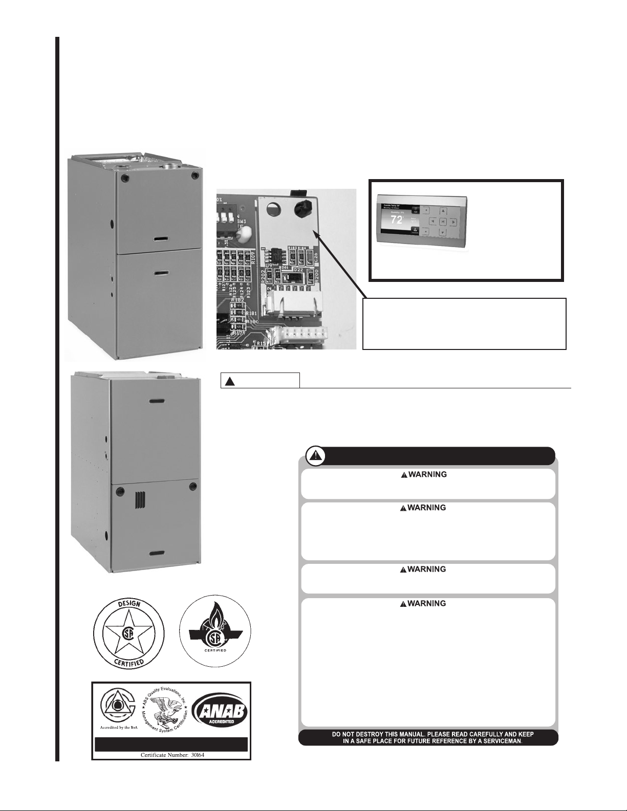
ISO 9001:2008
FOR RGPE UPFLOW, HORIZONTAL, RGLE DOWNFLOW 2 STAGE,
80+ GAS FURNACES
COMMUNICATING
THERMOSTATS
INSTALLATION
SEE PAGE 84
This Memory Card must be removed (broken away) from the
furnace control when the control is replaced. The card must
be inserted into the connector at J15 of the replacement control. Failure to retain this memory card with the furnace when
replacing the furnace control could result in no operation
when the furnace control is replaced.
WARNING
!
DO NOT EXCHANGE MEMORY CARDS BETWEEN 2 OR MORE DIFFERENT FURNACES. DOING
SO COULD RESULT IN UNEXPECTED OPERATION – INCLUDING INADEQUATE AIRFLOW DURING HEATING (AND OTHER MODES) OR A LOSS OF HEAT.
SUPERSEDES 92-24161-77-01
92-24161-77-02
Page 2

IMPORTANT: All Manufacturer products
meet current Federal OSHA Guidelines
for safety. California Proposition 65
warnings are required for certain products, which are not covered by the
OSHA standards.
California's Proposition 65 requires
warnings for products sold in California
that contain, or produce, any of over 600
listed chemicals known to the State of
California to cause cancer or birth
defects such as fiberglass insulation,
lead in brass, and combustion products
from natural gas.
All “new equipment” shipped for sale in
California will have labels stating that the
product contains and/or produces
Proposition 65 chemicals. Although we
have not changed our processes, having
the same label on all our products facilitates manufacturing and shipping. We
cannot always know “when, or if” products will be sold in the California market.
You may receive inquiries from customers about chemicals found in, or produced by, some of our heating and airconditioning equipment, or found in natural gas used with some of our products.
Listed below are those chemicals and
substances commonly associated with
similar equipment in our industry and
other manufacturers.
• Glass Wool (Fiberglass) Insulation
• Carbon Monoxide (CO)
• Formaldehyde
• Benzene
More details are available at the
Websites for OSHA (Occupational
Safety and Health Administration), at
www.osha.gov
and the State of
California's OEHHA(Office of
Environmental Health Hazard
Assessment), at www.oehha.org.
Consumer education is important since
the chemicals and substances on the list
are found in our daily lives. Most consumers are aware that products present
safety and health risks, when improperly
used, handled and maintained.
Installation Instructions are updated on a
regular basis. This is done as product
changes occur or if new information
becomes available. In this publication,
an arrow ➤ denotes changes from the
previous edition or additional new material.
IMPORTANT: To insure proper installation and operation of this product, completely read all instructions prior to
attempting to assemble, install, operate,
maintain or repair this product. Upon
unpacking of the furnace, inspect all
parts for damage prior to installation and
start-up.
TABLE OF CONTENTS
SAFETY INFORMATION..........................................................................................................................................3
INSTALLATION CHECK LIST...................................................................................................................................5
GENERAL INFORMATION.......................................................................................................................................6
IMPORTANTINFORMATION ABOUT EFFICIENCYANDINDOORAIR QUALITY...................................6
RECEIVING.....................................................................................................................................................7
LOCATION REQUIREMENTSANDCONSIDERATIONS.......................................................................................7
LOCATION.......................................................................................................................................................7
CLEARANCE-ACCESSIBILITY....................................................................................................................10
SITE SELECTION.........................................................................................................................................10
DUCTING......................................................................................................................................................10
COMBUSTIONAND VENTILATION AIR ...............................................................................................................12
COMBUSTIONAIR REQUIREMENTS........................................................................................................12
VENTING.................................................................................................................................................................16
GENERAL INFORMATION...........................................................................................................................16
DRAFTINDUCER.........................................................................................................................................16
FURNACE CATEGORY INFORMATION.....................................................................................................16
IMPORTANTAPPLICATIONNOTES...........................................................................................................16
B-1 VERTICALVENTING.............................................................................................................................17
SPECIAL VENT SYSTEMS..........................................................................................................................17
POWERVENT SYSTEMS...........................................................................................................................18
EXISTING VENT SYSTEMS........................................................................................................................18
GAS SUPPLYAND PIPING....................................................................................................................................19
GAS SUPPLY................................................................................................................................................19
GAS PIPING..................................................................................................................................................19
GAS PRESSURE..........................................................................................................................................20
LP CONVERSION.........................................................................................................................................20
SETTING GAS PRESSURE.........................................................................................................................21
ADJUSTING OR CHECKINGFURNACE INPUT.......................................................................................22
ELECTRICALWIRING............................................................................................................................................23
ELECTRICALCHECKS........................................................................................................................24
ACCESSORIES.......................................................................................................................................................25
FIELDINSTALLEDOPTIONACCESSORIES............................................................................................25
OTHERACCESSORIES AVAILABLE..........................................................................................................27
RXGW-B01 CHIMNEYADAPTER...............................................................................................................27
TYPICAL WIRING FOR SELECTACCESSORIESFOR COMMUNICATING RESIDENTIAL
SYSTEMS............................................................................................................................................27
80+ HIGH ALTITUDE INSTRUCTIONS.......................................................................................................29
LP GAS..........................................................................................................................................................29
ORIFICE ORDERING INFORMATION........................................................................................................29
ALTERNATE METHOD FOR CANADIAN HIGH-ALTITUDE DERATE......................................................29
AIRFLOW.................................................................................................................................................................31
INTEGRATED FURNACE CONTROL...................................................................................................................33
24 VAC THERMOSTAT INPUTS..................................................................................................................33
SPECIAL CONFIGURATION–COMMUNICATINGTHERMOSTATW/NON-COMM. CONDENSER......34
24 VAC FROM TRANSFORMERCONNECTIONS....................................................................................34
FUSE.............................................................................................................................................................34
115 VAC TERMINALS...................................................................................................................................34
INDUCED DRAFTMOTOROUTPUT.........................................................................................................34
NEUTRALTERMINALS................................................................................................................................35
ELECTRONICAIR CLEANER OUTPUT.....................................................................................................35
HUMIDIFIEROUTPUT.................................................................................................................................35
15-PIN MATE-N-LOK CONNECTOR...........................................................................................................35
COMMUNICATING ECM MOTOR COMMUNICATIONS CONNECTION.................................................36
SPARK IGNITIONTRANSFORMER...........................................................................................................37
R-J11 CONNECTOR.....................................................................................................................................37
COMMUNICATIONS NETWORK CONNECTION......................................................................................37
COMMUNICATIONS L.E.D.’S......................................................................................................................37
LEARNBUTTON...........................................................................................................................................38
MEMORY CARD CONNECTOR..................................................................................................................38
MEMORY CARD...........................................................................................................................................38
REPLACINGTHE FURNACE CONTROL...................................................................................................41
DIPSWITCHES.............................................................................................................................................44
SW1...............................................................................................................................................................44
SW2...............................................................................................................................................................46
FURNACE OPERATION USINGNON-COMMUNICATING SIINGLE-STAGE AND TWO-STAGE
THERMOSTATS......................................................................................................................................46
SW3-1AND SW3-2.......................................................................................................................................47
BIAS / TERMINATION ..................................................................................................................................48
DUALSEVEN-SEGMENT DIAGNOSTICDISPLAY ...................................................................................48
FAULT CODE BUFFER................................................................................................................................48
CLEARING DIAGNOSTICFAULT CODES FROM THE BUFFER.............................................................48
COMMUNICATING SYSTEMS....................................................................................................................49
START-UP PROCEDURES....................................................................................................................................57
IGNITOR PLACEMENT, ALIGNMENT& LOCATION.................................................................................57
TO START THE FURNACE..........................................................................................................................57
TO SHUT DOWN THE FURNACE..............................................................................................................57
SEQUENCE OF OPERATION.....................................................................................................................57
ADJUSTING OR CHECKINGFURNACE INPUT.......................................................................................59
MAINTENANCE.......................................................................................................................................................60
FILTERS ........................................................................................................................................................60
SYSTEM OPERATION INFORMATION......................................................................................................62
ANNUAL INSPECTION................................................................................................................................62
LUBRICATION...............................................................................................................................................62
REPLACEMENTPARTS..............................................................................................................................62
NOx MODELS...............................................................................................................................................62
TROUBLESHOOTING............................................................................................................................62-63
WIRING DIAGRAM.......................................................................................................................................79
THERMOSTATS......................................................................................................................................................80
NON-COMMUNICATINGTHERMOSTATS.................................................................................................80
SEQUENCE OF OPERATION.....................................................................................................................80
COMMUNICATING THERMOSTATS.....................................................................................................................84
2
Page 3
SAFETY INFORMATION
IMPORTANT!
THE COMMONWEALTH OF MASSACHUSETTS REQUIRES COMPLIANCE
WITH REGULATION 248 CMR 4.00
AND 5.00 FOR INSTALLATION OF
THROUGH-THE-WALL VENTED GAS
APPLIANCES AS FOLLOWS:
(a) For all side wall horizontally vented
gas fueled equipment installed in every
dwelling, building or structure used in
whole or in part for residential purposes,
including those owned or operated by
the Commonwealth and where the side
wall exhaust vent termination is less than
seven (7) feet above finished grade in
the area of the venting, including but not
limited to decks and porches, the following requirements shall be satisfied:
1. INSTALLATION OF CARBON
MONOXIDE DETECTORS.At the time of
installation of the side wall horizontal
vented gas fueled equipment, the
installing plumber or gasfitter shall
observe that a hard wired carbon
monoxide detector with an alarm and
battery back-up is installed on the floor
level where the gas equipment is to be
installed. In addition, the installing
plumber or gasfitter shall observe that a
battery operated or hard wired carbon
monoxide detector with an alarm is
installed on each additional level of the
dwelling, building or structure served by
the side wall horizontal vented gas
fueled equipment. It shall be the responsibility of the property owner to secure
the services of qualified licensed professionals for the installation of hard wired
carbon monoxide detectors.
a. In the event that the side wall horizontally vented gas fueled equipment is
installed in a crawl space or an attic, the
hard wired carbon monoxide detector
with alarm and battery back-up may be
installed on the next adjacent floor level.
b. In the event that the requirements of
this subdivision can not be met at the
time of completion of installation, the
owner shall have a period of thirty (30)
days to comply with the above requirements; provided, however, that during
said thirty (30) day period, a battery
operated carbon monoxide detector with
an alarm shall be installed.
2. APPROVED CARBON MONOXIDE
DETECTORS. Each carbon monoxide
detector as required in accordance with
the above provisions shall comply with
NFPA 720 and be ANSI/UL 2034 listed
and IAS certified.
3. SIGNAGE. A metal or plastic identification plate shall be permanently mounted to the exterior of the building at a
minimum height of eight (8) feet above
grade directly in line with the exhaust
vent terminal for the horizontally vented
gas fueled heating appliance or equipment. The sign shall read, in print size
no less than one-half (1/2) inch in size,
“GASVENT DIRECTLY BELOW. KEEP
CLEAR OF ALL OBSTRUCTIONS”.
4. INSPECTION. The state or local gas
inspector of the side wall horizontally
vented gas fueled equipment shall not
approve the installation unless, upon
inspection, the inspector observes carbon monoxide detectors and signage
installed in accordance with the provisions of 248 CMR 5.08(2)(a) 1 through
4.
(b) EXEMPTIONS: The following equip-
ment is exempt from 248 CMR
5.08(2)(a)1 through 4:
1. The equipment listed in Chapter 10
entitled “Equipment Not Required To Be
Vented” in the most current edition of
NFPA 54 as adopted by the Board; and
2. Product Approved side wall horizontally vented gas fueled equipment
installed in a room or structure separate from the dwelling, building or structure used in whole or in part for residential purposes.
(c) MANUFACTURER REQUIREMENTS – GAS EQUIPMENT VENTING SYSTEM PROVIDED. When the
manufacturer of Product Approved side
wall horizontally vented gas equipment
provides a venting system design or
venting system components with the
equipment, the instructions provided by
the manufacturer for installation of the
equipment and the venting system shall
include:
1. Detailed instructions for the installation of the venting system design or the
venting system components; and
2. A complete parts list for the venting
system design or venting system.
(d) MANUFACTURER REQUIREMENTS – GAS EQUIPMENT VENTING SYSTEM NOT PROVIDED. When
the manufacturer of a Product
Approved side wall horizontally vented
gas fueled equipment does not provide
the parts for venting the flue gases, but
identifies “special venting systems”, the
following requirements shall be satisfied by the manufacturer:
1. The referenced “special venting system” instructions shall be included with
the appliance or equipment installation
instructions; and
2. The “special venting systems” shall
be Product Approved by the Board, and
the instructions for that system shall
include a parts list and detailed installation instructions.
(e) A copy of all installation instructions
for all ProductApproved side wall horizontally vented gas fueled equipment,
all venting instructions, all parts lists for
venting instructions, and/or all venting
design instructions shall remain with
the appliance or equipment at the completion of the installation.
WARNING
!
INSTALLTHIS FURNACE ONLY IN
A LOCATION AND POSITION AS
SPECIFIED IN THE LOCATION
REQUIREMENTS AND CONSIDERATIONS SECTION OF THESE
INSTRUCTIONS. PROVIDE ADEQUATE COMBUSTION AND VENTILATION AIR TOTHE FURNACE
SPACE AS SPECIFIED IN THE
VENTING SECTION OF THESE
INSTRUCTIONS.
WARNING
!
PROVIDE ADEQUATE COMBUSTION AND VENTILATION AIR TO
THE FURNACE SPACE AS SPECIFIED IN THE COMBUSTION AND
VENTILATION AIR SECTION OF
THESE INSTRUCTIONS.
WARNING
!
COMBUSTION PRODUCTS MUST
BE DISCHARGED OUTDOORS.
CONNECT THIS FURNACE TO AN
APPROVEDVENT SYSTEM ONLY,
AS SPECIFIED IN VENT PIPE
INSTALLATION SECTION OF
THESE INSTRUCTIONS.
WARNING
!
NEVER TEST FOR GAS LEAKS
WITH AN OPEN FLAME. USE A
COMMERCIALLY AVAILABLE
SOAP SOLUTION MADE SPECIFICALLY FOR THE DETECTION OF
LEAKS TO CHECK ALL CONNECTIONS, AS SPECIFIED IN GAS
SUPPLY AND PIPING SECTION OF
THESE TION INSTRUCTIONS.
WARNING
!
THIS FURNACE IS NOT
APPROVED OR RECOMMENDED
FOR INSTALLATION ON ITS BACK,
WITH ACCESS DOORS FACING
UPWARDS, OR WITH SUPPLY AIR
DISCHARGING TO THE RIGHTHAND SIDE WHEN FACING THE
FRONT OF THE FURNACE. SEE
FIGURES 6 AND 7 FOR PROPER
INSTALLATION OF HORIZONTAL
MODELS.
WARNING
!
DO NOT INSTALLTHIS FURNACE
IN A MOBILE HOME!! THIS FURNACE IS NOT APPROVED FOR
INSTALLATION IN A MOBILE
HOME. DOING SO COULD CAUSE
FIRE, PROPERTY DAMAGE, PERSONAL INJURY OR DEATH.
WARNING
!
USE ONLYWITH TYPE OF GAS
APPROVED FOR THIS FURNACE.
REFER TO THE FURNACE RATING
PLATE.
3
Page 4
WARNING
!
WHENTHIS FURNACE IS INSTALLED
IN A RESIDENTIAL GARAGE,IT
MUST BE INSTALLED SO THE BURNERS AND IGNITION SOURCE ARE
LOCATED NO LESSTHAN 18 INCHES ABOVETHE FLOOR.THIS ISTO
REDUCETHE RISK OF IGNITING
FLAMMABLEVAPORS WHICH MAY
BE PRESENT IN A GARAGE.
ALSO,THE FURNACE MUST BE
LOCATED OR PROTECTEDTO
AVOID PHYSICAL DAMAGE BY VEHICLES. FAILURETO FOLLOWTHESE
WARNINGS CAN CAUSE A FIRE OR
EXPLOSION, RESULTING IN PROPERTY DAMAGE, PERSONAL INJURY
OR DEATH.
WARNING
!
USE OF THIS FURNACE IS
ALLOWED DURING CONSTRUCTION
IF THE FOLLOWINGTEMPORARY
INSTALLATION REQUIREMENTS
ARE MET. INSTALLATION MUST
COMPLY WITH ALL INSTALLATION
INSTRUCTIONS INCLUDING:
• PROPERVENT INSTALLATION;
• FURNACE OPERATING UNDER
THERMOSTATIC CONTROL;
• RETURN AIR DUCT SEALED TO
THE FURNACE;
• AIR FILTERS IN PLACE;
• SET FURNACE INPUT RATE AND
TEMPERATURE RISE PER RATING PLATE MARKING;
• MEANS FOR PROVIDING OUTDOOR AIR REQUIRED FOR COMBUSTION;
• RETURN AIR TEMPERATURE
MAINTAINED BETWEEN 55°F
(13°C) AND 80°F (27°C); AND;
• CLEAN FURNACE, DUCT WORK
AND COMPONENTS UPON SUBSTANTIAL COMPLETION OF THE
CONSTRUCTION PROCESS, AND
VERIFY FURNACE OPERATING
CONDITIONS INCLUDING IGNITION, INPUT RATE,TEMPERATURE RISE AND VENTING,
ACCORDINGTOTHE INSTRUCTIONS.
WARNING
!
DO NOT JUMPER OR OTHERWISE
BYPASS OVERTEMPERATURE OR
ANY OTHER LIMITS OR SWITCHES
ONTHE FURNACE. IF ONE OF
THESE LIMITS OR SWITCHES
SHOULDTRIP OR OPEN,THE USER
ISTO BE INSTRUCTEDTO CALL A
QUALIFIED INSTALLER, SERVICE
AGENCY OR THE GAS SUPPLIER.
FOR MANUALLY RESETABLE
SWITCHES,THE USER IS FURTHER
INSTRUCTEDTO NEVER RESETTHE
SWITCH, BUTTO CALL A QUALIFIED
TECHNICIAN. MANUAL RESET
SWITCHES MAY REQUIRE FURTHER
CORRECTIVE ACTIONS. FAILURETO
FOLLOWTHIS WARNING COULD
RESULT IN CARBON MONOXIDE
POISONING, SERIOUS INJURY OR
DEATH. IFTHE UNIT IS INSTALLED
IN A CLOSET,THE DOOR MUST BE
CLOSEDWHEN MAKINGTHIS
CHECK. INSTALLERS ANDTECHNICIANS ARE INSTRUCTEDTO
REPLACE ANY LIMIT OR SAFETY
SWITCH/DEVICE ONLY WITH IDENTICAL REPLACEMENT PARTS.
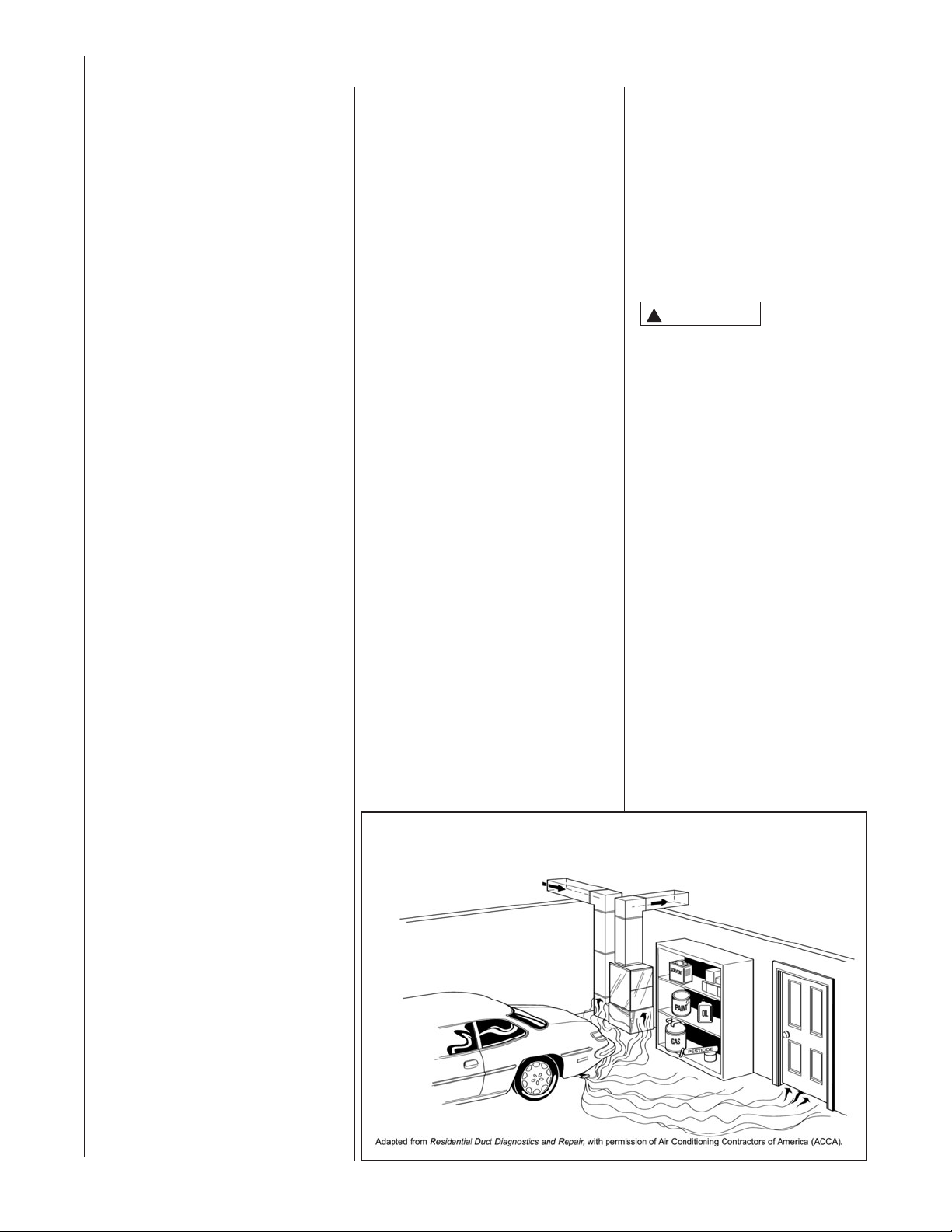
WARNING
!
DUCT LEAKS CAN CREATE AN
UNBALANCED SYSTEM AND DRAW
POLLUTANTS SUCH AS DIRT, DUST,
FUMES AND ODORS INTOTHE
HOME CAUSING PROPERTY DAMAGE. FUMES AND ODORS FROM
TOXIC,VOLATILE OR FLAMMABLE
CHEMICALS, AS WELL AS AUTOMOBILE EXHAUST AND CARBON
MONOXIDE (CO), CAN BE DRAWN
INTOTHE LIVING SPACETHROUGH
LEAKING DUCTS AND UNBALANCED DUCT SYSTEMS CAUSING
PERSONAL INJURY OR DEATH (SEE
FIGURE 5).
• IF AIR-MOVING EQUIPMENT OR
DUCTWORK IS LOCATED IN
GARAGES OR OFF-GARAGE
STORAGE AREAS - ALL JOINTS,
SEAMS, AND OPENINGS INTHE
EQUIPMENT AND DUCT MUST BE
SEALED TO LIMIT THE MIGRATION
OF TOXIC FUMES AND ODORS
INCLUDING CARBON MONOXIDE
FROM MIGRATING INTOTHE LIVING SPACE.
• IF AIR-MOVING EQUIPMENT OR
DUCTWORK IS LOCATED IN
SPACES CONTAINING FUEL
BURNING APPLIANCES SUCH AS
WATER HEATERS OR BOILERS ALL JOINTS, SEAMS, AND OPENINGS IN THE EQUIPMENT AND
DUCT MUST ALSO BE SEALED TO
PREVENT DEPRESSURIZATION
OF THE SPACE AND POSSIBLE
MIGRATION OF COMBUSTION
BYPRODUCTS INCLUDING CARBON MONOXIDE INTOTHE LIVING
SPACE.
WARNING
!
ALWAYS INSTALL FURNACE TO
OPERATE WITHIN THE FURNACE'S INTENDED TEMPERATURE-RISE RANGE WITH A DUCT
SYSTEM WHICH HAS AN EXTERNAL STATIC PRESSURE WITHIN
THE ALLOWABLE RANGE, AS
SPECIFIED IN DUCTING SECTION
OF THESE INSTRUCTIONS. SEE
ALSO FURNACE RATING PLATE.
WARNING
!
WHEN A FURNACE IS INSTALLED
SO THAT SUPPLY DUCTS CARRY
AIR CIRCULATED BY THE FURNACETO AREAS OUTSIDE THE
SPACE CONTAINING THE FURNACE,THE RETURN AIR SHALL
ALSO BE HANDLED BY DUCT(S)
SEALED TO THE FURNACE CASING AND TERMINATING OUTSIDE
THE SPACE CONTAININGTHE
FURNACE.
NOTICE
IMPROPER INSTALLATION, OR
INSTALLATION NOT MADE IN
ACCORDANCE WITHTHE CSA
INTERNATIONAL (CSA) CERTIFICATION OR THESE INSTRUCTIONS, CAN RESULT IN UNSATISFACTORY OPERATION AND/OR
DANGEROUS CONDI-TIONS AND
ARE NOT COVERED BY THE UNIT
WARRANTY.
NOTICE
IN COMPLIANCE WITH RECOGNIZED CODES, IT IS RECOMMENDED THAT AN AUXILIARY
DRAIN PAN BE INSTALLED
UNDER ALL EVAPORATOR COILS
OR UNITS CONTAINING EVAPORATOR COILS THAT ARE LOCATED IN ANY AREA OF A STRUCTURE WHERE DAMAGETOTHE
BUILDING OR BUILDING CONTENTS MAY OCCUR AS A RESULT
OF AN OVERFLOW OF THE COIL
DRAIN PAN OR A STOPPAGE IN
THE PRIMARY CONDENSATE
DRAIN PIPING. SEE ACCESSORIES SECTION OF THESE
INSTRUCTIONS FOR AUXILIARY
HORIZONTAL OVERFLOW PAN
INFORMATION (MODEL RXBM).
WARNING
!
DO NOT EXCHANGE MEMORY
CARDS BETWEEN 2 OR MORE
DIFFERENT FURNACES. DOING
SO COULD RESULT IN UNEXPECTED OPERATION – INCLUDING INADEQUATE AIRFLOW DURING HEATING (AND OTHER
MODES OR A LOSS OF HEAT).
4
Page 5

Before beginning any troubleshooting procedure, complete the following installation checklist. A furnace malfunction is sometimes caused by an improper installation. By completing this checklist, the problem may be found and corrected. Make copies
of the checklist and complete one for every Low Profile Furnace service call for your records.
INSTALLATION CHECKLIST
(Refer to this manual for specifics.)
GAS SUPPLY
Adequate pipe size
No gas leaks
Proper supply and manifold gas pressure (check with an accurate U-tube manometer with the furnace and all other
gas appliances operating.)
ELECTRICAL
Correct thermostat and subbase Thermostat model Subbase model
Correct thermostat mode and setting
Correct line supply voltage
Correct power supply polarity is required with electronic ignition
Correct furnace ground to electrical panel
DC microamp (∝A) flame signal (hot surface ignition units)
Correct control voltage
Measure and set heat anticipator amperage
Air conditioning low voltage wires connected to terminals “Y” “C” - not with wire nuts
VENTING
Correct vent pipe diameter and length (according to CSA tables) Vent connection size
Correct venting material (according to CSA tables)
Correct lining for masonry chimneys
Adequate clearance from combustibles
Proper negative pressure reading in the vent
Vent pipe secured to induced draft blower housing
COMBUSTION AIR
Proper source of combustion air Optional attic combustion air pull
Correct combustion air opening size Non-attic combustion air pull
FURNACE INSTALLATION
Adequate clearance from combustibles
Adequate clearance for service
Proper air temperature rise (See furnace rating plate)
External static pressure inches w.c.
Correct filter(s)
Correct cooling coil or accessories (if equipped)
Adequate supply and return air ducting ReturnAir Duct Size SupplyAir Duct Size
Air ducts sealed to prevent leakage
5
Page 6
GENERAL INFORMATION
The RGPE/RGLE series furnaces are
design certified by CSA for use with natural and propane gasesas follows:
As a CategoryI furnace, it may be
vented vertically with type B-1 vent
pipe and alsomay be common vented as described in these instructions.
This furnace should be installed in accordancewith the American National
Standard Z223.1 - latest edition booklet
entitled “National Fuel Gas Code” (NFPA
54) (in Canada, CSAB149.1 and .2
Installation Codes for gas burning appliances), and the requirements or codes of
the localutility or other authorityhaving
jurisdiction including local plumbing or
wastewater codes.
The NationalAppliance Energy
ConservationAct (NAECA) of 1987
states that any gas furnace manufacturedafter January 1, 1992, must have a
minimumAnnual Fuel Utilization
Efficiency (AFUE) of 78%.The higher the
AFUE percentage the more usableheat
energy the consumer gets for every dollar of fuel purchased.This is similarto
the EPA's minimum gas mileage requirement for automobiles. It gives the consumera relativelyeasy way to make
direct efficiency comparisons between
differentfurnace brands and styles.
A high AFUE value, which translates into
a low operating cost, is not the only concern thatconsumers have. Theyalso
want a furnace with a reasonable
installed cost. They want a furnace that
provides them with comfort – their main
concern.And they expecta furnace with
exceptional reliability and longevity.
Gas furnace manufacturers are always
striving to provide consumers with the
best furnace value. The Low Profile
Furnace addresses all those consumer
needs. It gives exceptionalefficiency with
a low installationcost. It delivers the
comfort the customer wants along with
the reliability they expect.
The key to all these customer benefits is
the furnace's heat exchanger.The materialsused to construct the furnace in general and the heatexchanger in particular
make it a rugged,long lasting unit. The
unique heat exchanger design provides
the customer with a furnace only 34 inches high.This gives the consumer a unit
easily installed in almost every location
that accepts all customary accessories.
With the introduction of higherefficiency
furnaces, special attention mustbe paid
to the venting system.Only listed venting
systems may be used as stated in the
installation instructions and the National
Fuel Gas Code, ANSI Z223.1 (NFPA 54),
or the Canadian CAN/CGA B149.1 and
B149.2 InstallationCodes for Gas
Burning Appliances.Sincefurnace tech-
nology and ventingrequirements are
changing, awarenessof local, state, and
federal codes and industry changes is
imperative.
NOTE: Always perform a proper heat
loss calculation beforespecifying the furnace size. This ensures that the furnace
is sized to adequately, economically, heat
the building and provide the correct airflow for yourapplication.
IMPORTANT:PROPERAPPLICATION,
INSTALLATION AND MAINTENANCE
OF THIS FURNACE ISA MUST IF
CONSUMERSARE TO RECEIVE THE
FULLBENEFITS FOR WHICH THEY
HAVE PAID.
Additionalhelpful publications available
from the “NationalFire Protection
Association” are: NFPA-90A– Installation
ofAir Conditioning and Ventilating
Systems 1985 or latestedition.NFPA90B – WarmAir Heating and Air
Conditioning Systems 1984.
Thesepublications are availablefrom:
National Fire Protection Association,
Inc.
Batterymarch Park
Quincy, MA 02269
CSA-INTERNATIONAL
178 Rexdale Blvd.
Etobicoke (Toronto), Ontario
Canada M9W, 1R3
IMPORTANT INFORMATION
ABOUT EFFICIENCY AND
INDOOR AIR
QUALITY
Central cooling and heating equipment
is only as efficient as the duct system
that carries the cooled or heated air. To
maintain efficiency, comfort and good
indoor air quality, it is important to have
the proper balance between the air
being supplied to each room and the air
returning to the cooling and heating
equipment.
FIGURE 1
MIGRATION OF DANGEROUS SUBSTANCES, FUMES, AND ODORS INTO LIVING SPACES
Proper balance and sealing of the
duct system improves the efficiency
of the heating and air conditioning
system and improves the indoor air
quality of the home by reducing the
amount of airborne pollutants that
enter homes from spaces where the
ductwork and / or equipment is
located. The manufacturer and the
U.S. Environmental Protection
Agency’s Energy Star Program recommend that central duct systems
be checked by a qualified contractor
for proper balance and sealing.
WARNING
!
DUCT LEAKS CAN CREATE AN
UNBALANCED SYSTEM AND
DRAW POLLUTANTS SUCH AS
DIRT, DUST,FUMES AND ODORS
INTOTHE HOME CAUSING PROPERTY DAMAGE. FUMES AND
ODORS FROM TOXIC,VOLATILE
OR FLAMMABLE CHEMICALS, AS
WELL AS AUTOMOBILE
EXHAUST AND CARBON MONOXIDE (CO), CAN BE DRAWN INTO
THE LIVING SPACETHROUGH
LEAKING DUCTS AND UNBALANCED DUCT SYSTEMS CAUSING PERSONAL INJURY OR
DEATH (SEE FIGURE 1).
• IF AIR-MOVING EQUIPMENT OR
DUCTWORK IS LOCATED IN
GARAGES OR OFF-GARAGE
STORAGE AREAS - ALL
JOINTS, SEAMS, AND OPENINGS IN THE EQUIPMENT AND
DUCT MUST BE SEALED TO
LIMIT THE MIGRATION OF
TOXIC FUMES AND ODORS
INCLUDING CARBON MONOXIDE FROM MIGRATING INTO
THE LIVING SPACE.
• IF AIR-MOVING EQUIPMENT OR
DUCTWORK IS LOCATED IN
SPACES CONTAINING FUEL
BURNING APPLIANCES SUCH
6
Page 7
AS WATER HEATERS OR BOILERS
- ALL JOINTS, SEAMS, AND OPENINGS IN THE EQUIPMENT AND
DUCT MUST ALSO BE SEALED TO
PREVENT DEPRESSURIZATION OF
THE SPACE AND POSSIBLE
MIGRATION OF COMBUSTION
BYPRODUCTS INCLUDING CARBON MONOXIDE INTOTHE LIVING
SPACE.
NOTICE
IMPROPER INSTALLATION, OR
INSTALLATION NOT MADE IN
ACCORDANCE WITHTHE CSA
INTERNATIONAL (CSA) CERTIFICATION OR THESE INSTRUCTIONS,
CAN RESULT IN UNSATISFACTORY
OPERATION AND/OR DANGEROUS
CONDI-TIONS AND ARE NOT COVERED BY THE UNIT WARRANTY.
NOTICE
IN COMPLIANCE WITH RECOGNIZED
CODES, IT IS RECOMMENDEDTHAT
AN AUXILIARY DRAIN PAN BE
INSTALLED UNDER ALL EVAPORATOR COILS OR UNITS CONTAINING
EVAPORATOR COILS OR GAS FURNACES USED WITH EVAPORATOR
COILS THAT ARE LOCATED IN ANY
AREA OF A STRUCTURE WHERE
DAMAGETO THE BUILDING OR
BUILDING CONTENTS MAY OCCUR
AS A RESULT OF AN OVERFLOW OF
THE COIL DRAIN PAN OR A STOPPAGE IN THE PRIMARY CONDENSATE DRAIN PIPING.
RECEIVING
Immediately upon receipt, all cartons
and contents should be inspected for
transit damage. Units with damaged
cartons should be opened immediately.
If damage is found, it should be noted
on the delivery papers, and a damage
claim filed with the last carrier.
• After unit has been delivered to job
site, remove carton taking care not to
damage unit.
• Check the unit rating plate for unit
size, electric heat, coil, voltage,
phase, etc. to be sure equipment
matches what is required for the job
specification.
• Read the entire instructions before
starting the installation.
• Some building codes require extra
cabinet insulation and gasketing
when unit is installed in attic applications.
• If installed in an unconditioned
space, apply caulking around the
power wires, control wires, refrigerant
tubing and condensate line where
they enter the cabinet. Seal the
power wires on the inside where they
exit conduit opening. Caulking is
required to prevent air leakage into
and condensate from forming inside
the unit, control box, and on electrical
controls.
• Install the unit in such a way as to
allow necessary access to the
coil/filter rack and blower/control
compartment.
• Install the unit in a level position
to ensure proper condensate
drainage. Make sure unit is level
in both directions within 1/8”.
• Install the unit in accordance with
any local code which may apply
and the national codes. Latest
editions are available from:
“National Fire Protection
Association, Inc., Batterymarch
Park, Quincy, MA 02269.” These
publications are:
• ANSI/NFPANo. 70-(Latest
Edition) National Electrical Code.
• NFPA90AInstallation of Air
Conditioning and Ventilating
Systems.
• NFPA90B Installation of warm air
heating and air conditioning systems.
• The equipment has been evaluated in accordance with the Code of
Federal Regulations, Chapter XX,
Part 3280.
LOCATION REQUIREMENTS AND CONSIDERATIONS
GENERAL INFORMATION
1. NOTE: This furnace is shipped with
heat exchanger support brackets
installed under the back of the heat
exchanger.These may be removed
before installation, but it is not
required.
LOCATION
!
WARNING
THIS FURNACE IS NOT APPROVED
FOR INSTALLATION IN A MOBILE
HOME. DO NOT INSTALLTHIS FURNACE IN A MOBILE HOME.
INSTALLATION IN A MOBILE HOME
COULD CAUSE FIRE, PROPERTY
DAMAGE, PERSONAL INJURY OR
DEATH.
2. IMPORTANT: This furnace is not
approved or recommended for installation on its back, with access doors
facing upwards.
3. This furnace is suitable for installation in buildings constructed on-site.
This heating unit should be centralized with respect to the heat distribution system as much as practicable.
4. NOTE: These furnaces are approved
for installation in attics, as well as
alcoves, utility rooms, closets and
crawlspaces.
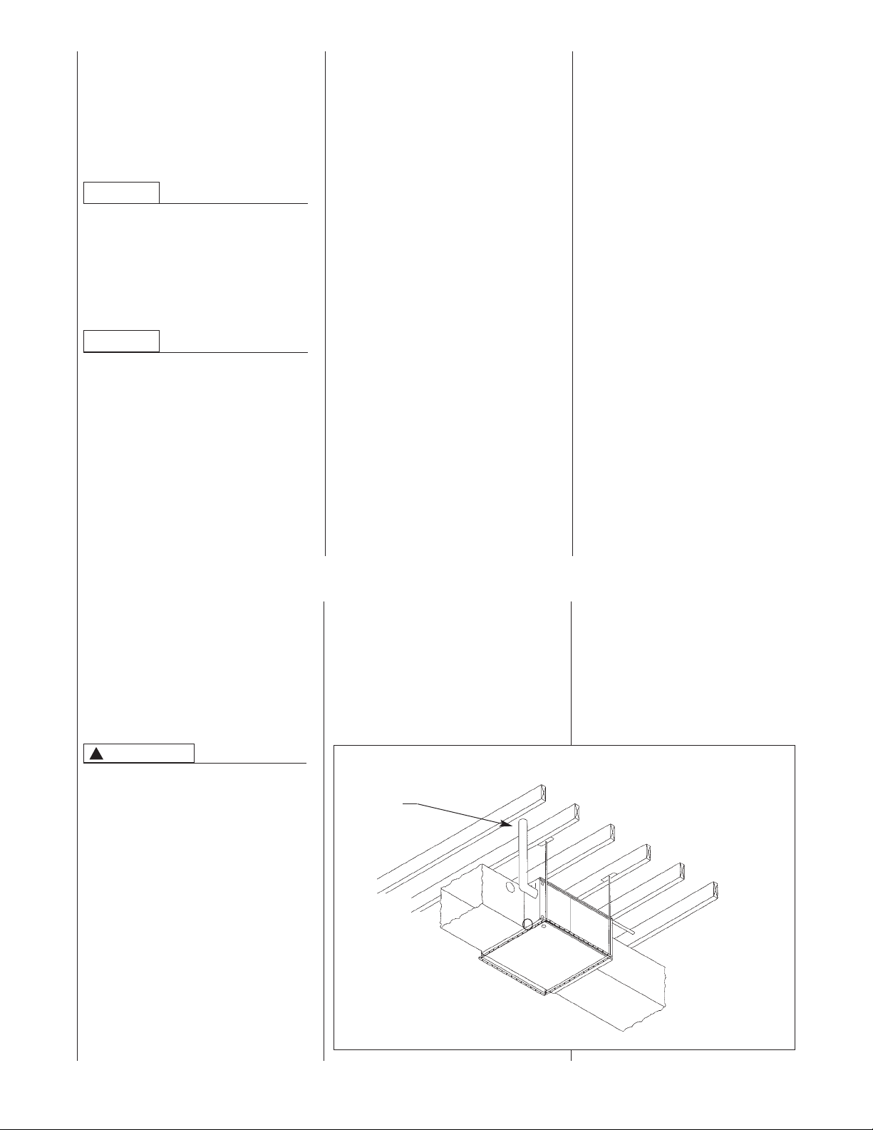
5. IMPORTANT: Support this unit when
installed.Forattic or crawl space
installation, horizontal furnaces may
be installed on combustible wood
flooring or by using support brackets.
See Figure 2.
FIGURE 2
HORIZONTAL FURNACE INSTALLEDW/SUPPORT BRACKETS
EXHAUST
VENT
NOTE: Do not block furnace
access with support rods. Maintain
clearances recommended in Figure 3.
Allow enough space for proper service
maintenance or replacement of the heat
exchanger and blower assembly.
6. IMPORTANT: If installing in a util-
ity room, be sure the door is wide
enough to:
a. allow the largest part of the furb. allow any other appliance
nace to pass; or
(such as a water heater) to
pass.
ST-A0799-01
7
Page 8
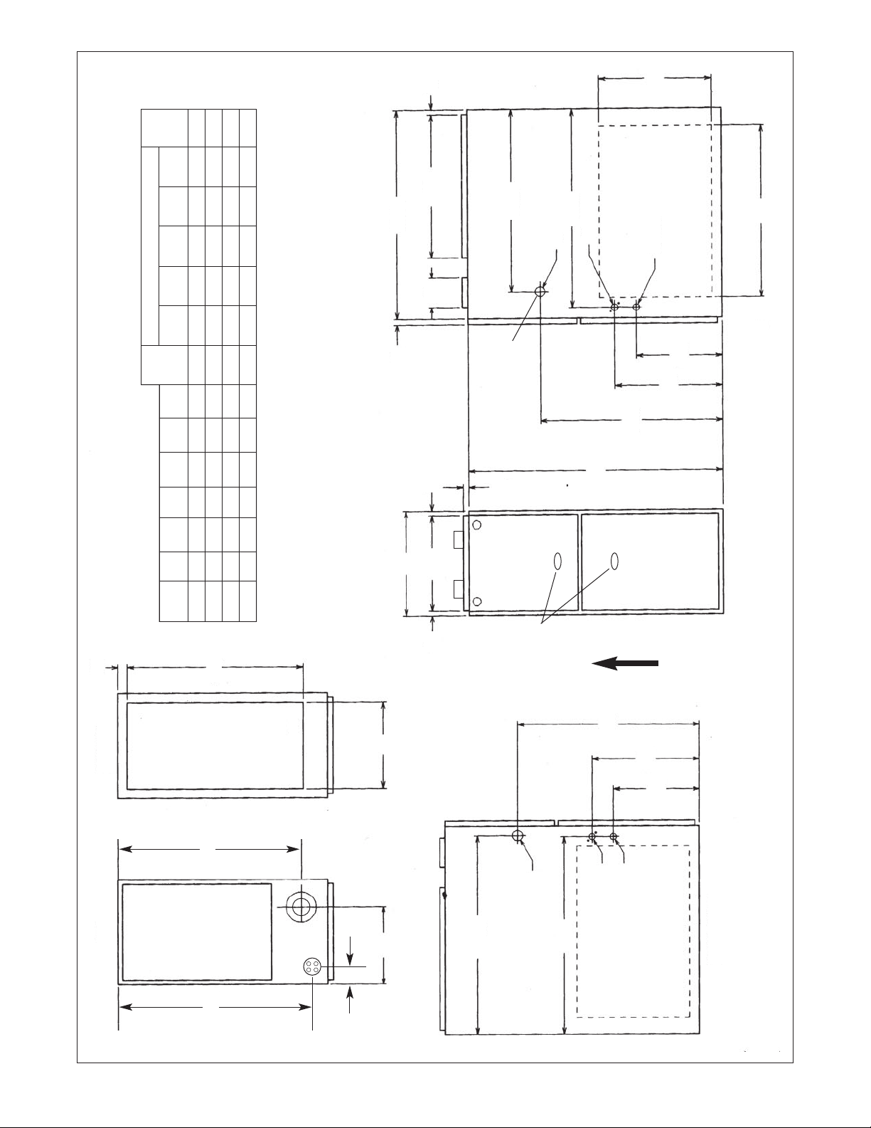
FIGURE 3
UPFLOW/HORIZONTAL DIMENSIONS
Ship.
/32
19
15
REDUCED CLEARANCE (IN.)
Back Top Front Vent
Left Right
A B C D E F
20
/16
1
28
➂ May be 1” with type B vent.
➀ May require 3” to 4” or 3” or 5” adapter.
➁ May be 0” with type B vent.
/2 0 3➁ 0 1 3 6➂ 105 lbs.
/2 0 3➁ 0 1 3 6➂ 115 lbs.
/2 0 0 0 1 3 6➂ 120 lbs.
1
/8 ➀ 15 2
3
/32 12
11
/2 16
1
/2 0 0 0 1 3 6➂ 140 lbs.
1
1
1
/2 2
1
/8 ➀ 15 2
/8 ➀ 18
/8 ➀ 22 2
3
1
7
/32 12
/32 14
/32 15
11
27
11
/2 16
/2 23
1
1
D
/16
9
/32
19
B
A
/16
7
24
5
ALTERNATE
GAS CONNECTION
/4
3
/8 DIA.
1
/8
5
26
/8 DIA.
7
/8 DIA.
7
OPTIONAL RETURN AIR CUTOUT
/2
1
(EITHER SIDE) FOR USE WITH
EXTERNAL SIDE FILTER FRAME*
23
11
/8
3
14
/32
11
RIGHT SIDE
24
34
FRONT
CLEARANCE TO COMBUSTIBLE MATERIAL (INCHES)
UPFLOW/HORIZONTAL MODELS
/4
1
1
BOTTOM
TOP
RGPE Side Side Wgts.
Model
05 17
07(A) 17
/32
17
23
AIR
RETURN
/2
1
24
AIR
SUPPLY
25.406
12 24
07(B),10 21 19
/32
19
SIGHT
GLASS
*Both sides for 1800 CFM or above.
AIRFLOW
/32
11
E
/16
C
13
26
/8
5
26
GAS CONNECTION
F
24
/8
3
14
/2
1
11
LOW VOLTAGE
ELECTRICAL CONNECTION
OPTIONAL RETURN AIR CUTOUT
(EITHER SIDE) FOR USE WITH
EXTERNAL SIDE FILTER FRAME*
LEFT SIDE
IMPORTANT: This furnace is not approved or recommended for
installation on its back, with access doors facing upwards.
8
Page 9
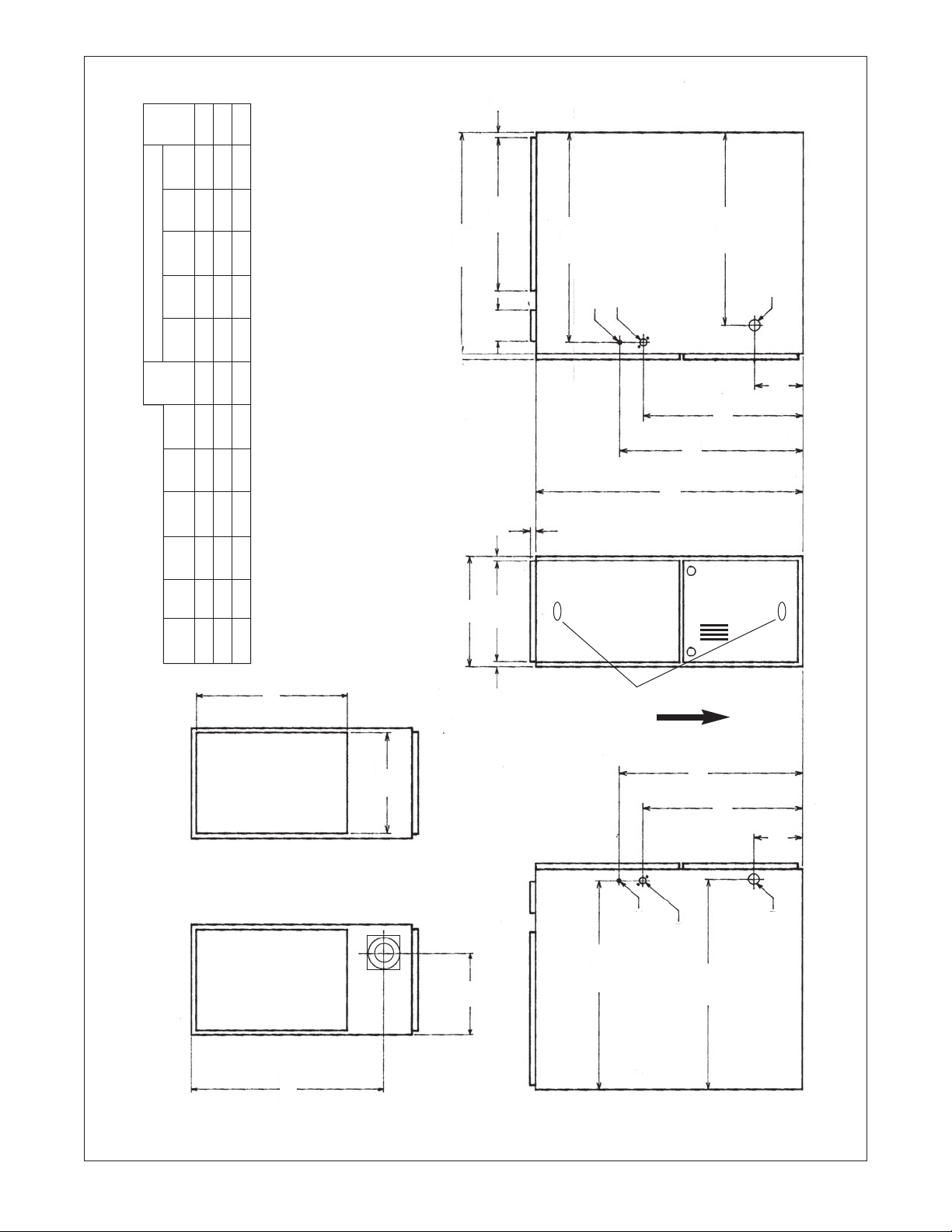
FIGURE 4
DOWNFLOW DIMENSIONS
Ship.
Back Top Front Vent
REDUCED CLEARANCE (IN.)
/8
5
/8
1
20
/16
1
28
➂ May be 1” with type B vent.
➀ May require 3” to 4” or 3” or 5” adapter.
➁ May be 0” with type B vent.
/8
5
26
/8 DIA.
/8 DIA.
7
7
/16
7
24
/8 DIA.
5
1
D
Left Right
A B C D E
CLEARANCE TO COMBUSTIBLE MATERIAL (INCHES)
Model
DOWNFLOW MODELS
RGLE Side Side Wgts.
/16
3
/8
/8 0 0 0 1 3 6➂ 140 lbs.
/8 0 3➁ 0 1 3 6➂ 105 lbs.
/8 0 0 0 1 3 6➂ 120 lbs.
5
1
5
3
20
/8
3
6
23
/8 ➀ 23
/8 ➀ 16
/8 ➀ 20
1
7
5
/32 12
/32 13
/32 15
11
27
11
/2 16
/2 23
1
1
12 24
07(A) 17
07(B),10 21 19
/4
3
19
/8
5
R.A.
B
A
/8
5
/4
3
SIGHT
34
GLASS
AIRFLOW
S.A.
AIR
E
SUPPLY
/8
3
23
/8
3
20
/16
3
6
TOP BOTTOM
AIR
RETURN
1
/2
24
/8
5
26
C
LOW VOLTAGE
/16
13
26
GAS CONNECTION
ELECTRIC CONNECTION
NOTE: IN DOWNFLOW CONFIGURATION, OPTIONAL AIR CUTOUT IS NOT PERMITTED.
COMBUSTIBLE FLOOR BASE REQUIRED IF FURNACE IS NOT INSTALLED ON COIL BOX.
9
Page 10
CLEARANCE –
ACCESSIBILITY
The design of forced air furnaces with
input ratings as listed in the tables on
the following pages are certified by
CSA for the clearances to combustible
materials shown in inches.
See name/rating plate and clearance
label for specific model number and
clearance information.
Service clearance of at least 24 inches
is recommended in front of all furnaces.
ACCESSIBILITY CLEARANCES,
WHERE GREATER, MUST TAKE
PRECEDENCE OVER FIRE PROTECTION CLEARANCES.
!
WARNING
UPFLOW AND HORIZONTAL
FURNACES MUST NOT BE
INSTALLED DIRECTLY ON CARPETING, TILE OR OTHER COMBUSTIBLE
MATERIAL OTHER THAN WOOD
FLOORING. INSTALLATION ON A
COMBUSTIBLE MATERIAL CAN
RESULT IN FIRE CAUSING PROPERTY DAMAGE, SEVERE PERSONAL
INJURY OR DEATH.
A gas-fired furnace for installation in a
residential garage must be installed so
that the burner(s) and the ignition
source are located not less than 18”
above the floor and the furnace is located or protected to avoid physical damage by vehicles.
!
WARNING
DOWNFLOW UNIT DESIGN IS CERTIFIED FOR INSTALLATION ON NONCOMBUSTIBLE FLOOR. A SPECIAL
COMBUSTIBLE FLOOR SUB-BASE,
FIGURE 5, IS REQUIRED WHEN
INSTALLING ON A COMBUSTIBLE
FLOOR. FAILURETO INSTALLTHE
SUB-BASE MAY RESULT IN FIRE,
PROPERTY DAMAGE, PERSONAL
INJURY OR DEATH.THIS SPECIAL
BASE IS OFFERED AS AN ACCESSORY FROM THE FACTORY. SEE THE
CLEARANCE LABEL LOCATED
INSIDE THE FURNACE FOR THE
APPROPRIATE MODEL NUMBER.
THE SPECIAL BASE IS NOT
REQUIRED WHEN THE FURNACE IS
INSTALLED ON TOP OF AN AIR
CONDITIONING PLENUM.
SITE SELECTION
1. Select a site in the building near the
center of the proposed, or existing,
duct system.
2. Give consideration to the vent system piping when selecting the furnace location. Be sure the venting
system can travel from the furnace to
the termination with minimal length
and elbows.
3. Locate the furnace near the existing
gas piping. Or, if running a new gas
line, locate the furnace to minimize
the length and elbows in the gas piping.
4. Locate the furnace to maintain proper clearance to combustibles as
shown in Figures 3 and 4.
!
CAUTION
WHEN COILS ARE INSTALLED
ABOVE A FINISHED CEILING OR
LIVING AREA, IT IS RECOMMENDED
THAT AN AUXILIARY SHEET METAL
CONDENSATE DRAIN PAN BE FABRICATED AND INSTALLED UNDER
ENTIRE UNIT. FAILURETO DO SO
CAN RESULT IN PROPERTY DAMAGE. RUN CONDENSATETO A
LOCATION WHERE IT IS NOTICEABLE.
!
WARNING
COMBUSTIBLE MATERIAL MUST
NOT BE PLACED ON OR AGAINST
THE FURNACE JACKET OR WITHIN
THE SPECIFIED CLEARANCES OF
THE VENT PIPE. THE AREA AROUND
THE FURNACE MUST BE KEPT
CLEAR AND FREE OF ALL COMBUSTIBLE MATERIALS INCLUDING
GASOLINE AND OTHER FLAMMABLE VAPORS AND LIQUIDS.
PLACEMENT OF COMBUSTIBLE
MATERIALS ON, AGAINST OR
AROUNDTHE FURNACE JACKET
CAN CAUSE AN EXPLOSION OR
FIRE RESULTING IN PROPERTY
DAMAGE, PERSONAL INJURY OR
DEATH.THE FURNACE OWNER
SHOULD BE CAUTIONED THATTHE
FURNACE AREA MUST NOT BE
USED AS A BROOM CLOSET OR
FOR ANY OTHER STORAGE PURPOSES.
DUCTING
Proper air flow is required for the
correct operation of this furnace. Too
little air flow can cause erratic operation and can damage the heat
exchanger. The duct system must
carry the correct amount of air for
heating and cooling. Position the
unit to minimize long runs or runs
with many turns and elbows.
Size and install the ducts according
to acceptable industry standards
and methods. The total static pressure drop (including evaporator coil,
if used) of the entire system should
not exceed 0.8” w.c.
adequate space for unit filter. NOTE:
Airflow external static pressure measurements do not include filter or
coil.
IMPORTANT: Some high efficiency
filters have a greater than normal
resistance to air flow.This can
adversely affect furnace operation.
BE SURE TO CHECK AIR FLOW if
using any filter other than the factory-provided filter.
NOTE: DO NOT take return air from
bathrooms, kitchens, furnace rooms,
garages, utility or laundry rooms, or
cold areas.
IMPORTANT: Return air tempera-
ture must be above 55°F during the
heating season.
!
WARNING
NEVER ALLOW PRODUCTS OF
COMBUSTION OR THE FLUE
PRODUCTSTO ENTER THE
RETURN AIR DUCTWORK, OR
THE CIRCULATING AIR SUPPLY.
ALL RETURN DUCTWORK MUST
BE ADEQUATELY SEALED AND
SECURED TO THE FURNACE
WITH SHEET METAL SCREWS,
AND JOINTS TAPED.WHEN A
FURNACE IS MOUNTED ON A
PLATFORM,WITH RETURN
THROUGHTHE BOTTOM, IT MUST
BE SEALED AIRTIGHT BETWEEN
THE FURNACE AND THE RETURN
AIR PLENUM. THE RETURN AIR
PLENUM MUST BE PERMANENTLY ENCLOSED. NEVER USE A
DOOR AS A PART OF THE
RETURN AIR PLENUM. THE
FLOOR OR PLATFORM MUST
PROVIDE SOUND PHYSICAL
SUPPORT OF THE FURNACE,
WITHOUT SAGGING, CRACKS,
GAPS, ETC., AROUND THE BASE
AS TO PROVIDE A SEAL
BETWEEN THE SUPPORT AND
THE BASE.
Be sure to have
10
Page 11
FAILURE TO PREVENT PRODUCTS
OF COMBUSTION FROM BEING CIRCULATED INTO THE LIVING SPACE
CAN CREATE POTENTIALLY HAZARDOUS CONDITIONS, INCLUDING
CARBON MONOXIDE POISONING
THAT COULD RESULT IN PERSONAL
INJURY OR DEATH.
DO NOT, UNDER ANY CIRCUMSTANCES, CONNECT RETURN OR
SUPPLY DUCTWORK TO OR FROM
ANY OTHER HEAT PRODUCING
DEVICE SUCH AS A FIREPLACE
INSERT, STOVE, ETC. DOING SO
MAY RESULT IN FIRE, CARBON
MONOXIDE POISONING, EXPLOSION, PERSONAL INJURY OR PROPERTY DAMAGE.
!
WARNING
BLOWER AND BURNERS MUST
NEVER BE OPERATEDWITHOUT
THE BLOWER DOOR IN PLACE.THIS
IS TO PREVENT DRAWING GAS
FUMES (WHICH COULD CONTAIN
HAZARDOUS CARBON MONOXIDE)
INTOTHE HOME THAT COULD
RESULT IN PERSONAL INJURY OR
DEATH.
UPFLOW UNITS
1. Set furnace in place and connect the
return duct or return air cabinet to
unit. Make the connection air-tight to
prevent entraining combustion gases
from any adjacent fuel-burning appliances. Unit return air may be connected on the sides or bottom of the
return air compartment.
a. Openings in the side must be cut
out the full width of the knockouts
on the unit. If using side return air,
THE BOTTOM base plate must be
installed.
NOTE: Where the maximum airflow
is 1800 CFM or more, both sides or
the bottom must be used for return
air.
b. If using bottom return air, place fur-
nace over return air plenum and
seal furnace bottom to return air
plenum.
!
WARNING
A SOLID METAL BASE PLATE, (SEE
TABLE 1) MUST BE IN PLACE WHEN
THE FURNACE IS INSTALLED WITH
SIDE AIR RETURN DUCTS. FAILURE
TO INSTALL A BASE PLATE COULD
CAUSE PRODUCTS OF COMBUSTION TO BE CIRCULATED INTO THE
LIVING SPACE AND CREATE POTENTIALLY HAZARDOUS CONDITIONS,
INCLUDING CARBON MONOXIDE
POISONING OR DEATH.
TABLE 1
FURNACE BASE BASE
WIDTH PLATE NO. PLATE SIZE
1
17
/2” RXGB-D17 151/8” x 239/16”
21” RXGB-D21 18
1
24
/2” RXGB-D24 255/8” x 239/16”
5
/8” x 239/16”
2. If summer air conditioning is desired,
position the indoor coil on the supply
air side of the furnace. Insure that no
air can bypass this coil.
3. Connect the supply air plenum to the
furnace plenum opening, or indoor
coil.
NOTE: The RGLE has louvers to cool
the inducer motor bearings.
DOWNFLOW UNITS
!
WARNING
THE DOWNFLOW FURNACE DESIGN
IS CERTIFIED FOR INSTALLATION
ON A NON-COMBUSTIBLE FLOOR.
IF INSTALLED ON A COMBUSTIBLE
FLOOR, USE THE SPECIAL BASE
SPECIFIED ON THE FURNACE
CLEARANCE LABEL. FAILURETO
INSTALLTHE SPECIAL BASE MAY
RESULT IN FIRE, PROPERTY DAMAGE, PERSONAL INJURY OR
DEATH.THIS SPECIAL BASE IS
SHIPPED FROM THE FACTORY AS
AN ACCESSORY.
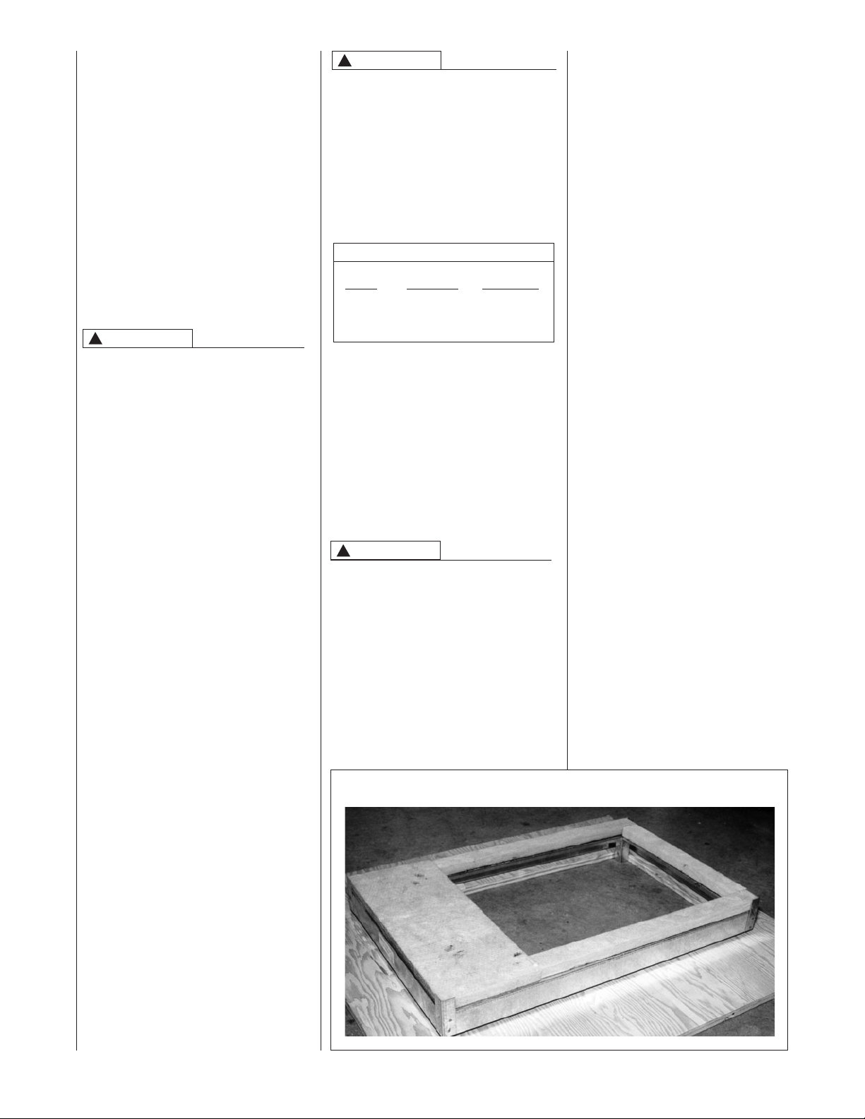
FIGURE 5
COMBUSTIBLE FLOOR BASE (RXGC-B17, -B21, -B24)
1. Position the unit over the supply
air plenum and connect.
a. If installing on a combustible
floor and not using an evapo-
rator coil box, install the special combustible floor base. See
Figure 5.
b. If summer air conditioning is
desired, position the indoor coil
on the supply air side. Insure
that no air can bypass this coil.
2. Connect the return air ducting to
the return air opening at the top of
the unit. Make the connection air
tight to prevent entraining combustion gases from an adjacent
fuel-burning appliance.
HORIZONTAL UNITS
1. Unit can be mounted left or right
side airflow configuration.
2. Position the unit on adequate
supports or by using support
brackets (see Figure 2) and connect supply plenum and return.
3. If summer air conditioning is
desired, position the indoor coil
on the supply air side of the unit.
Insure that no air can bypass this
coil.
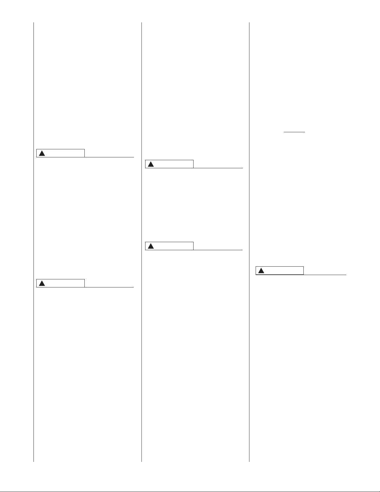
4. Secure the four angle brackets
shipped with the unit to the return
air opening. See Figure 6.
Connect the return air ducting to
the return air opening at the top of
the unit. Make the connection air
tight to prevent entraining combustion gases from an adjacent
fuel-burning appliance.
NOTE: Do not block furnace access
with support rods. Maintain clearances recommended in Figure 3.
Allow enough space for proper service maintenance or replacement of
the heat exchanger and blower
assembly.
11
Page 12
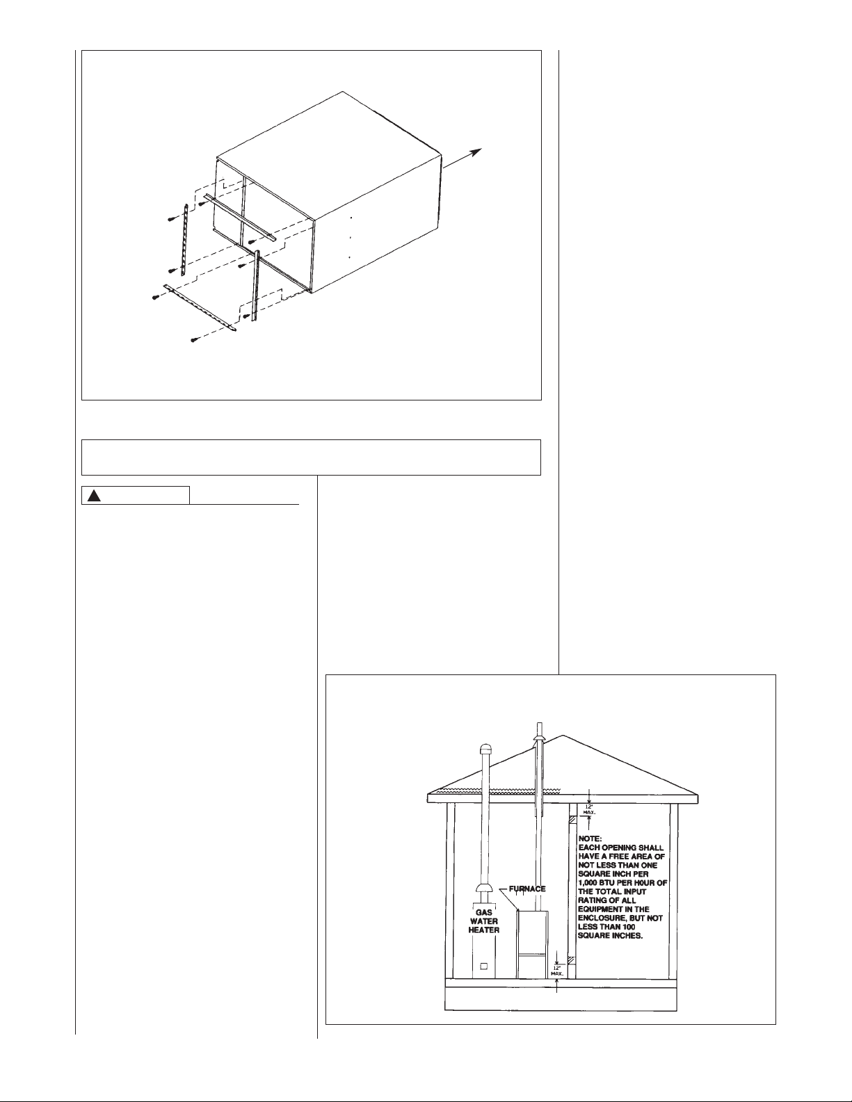
FIGURE 6
HORIZONTAL RETURN AIR DUCT
(LEFT-HAND AIRFLOW POSITION SHOWN)
AIRFLOW
RETURN
REAR VIEW
FOUR ANGLE BRACKETS ARE SHIPPED WITH EACH
UNIT THAT CAN BE USED TO SECURE THE RETURN
AIR DUCT TO A HORIZONTAL UNIT.
COMBUSTION AND VENTILATION AIR
IMPORTANT: This is not a direct vent furnace. Review venting instructions
before installing.
• Commercial buildings
• Buildings with indoor pools
• Furnaces installed in laundry
rooms
• Furnaces in hobby or craft rooms
• Furnaces installed near chemical
storage areas.
Exposure to the following substances in the combustion air supply
may also require OUTDOOR AIR for
combustion:
• Permanent wave solutions
• Chlorinated waxes and cleaners
• Chlorine-based swimming pool
chemicals
• Water softening chemicals
• De-icing salts or chemicals
• Carbon tetrachloride
• Halogen type refrigerants
• Cleaning solvents (such as
perchloroethylene)
• Printing inks, paint removers,
varnishes, etc.
• Hydrochloric acid
• Cements and glues
• Antistatic fabric softeners for
clothes dryers
• Masonry acid washing materials
!
WARNING
THIS FURNACE AND ANY OTHER
FUEL-BURNING APPLIANCE MUST
BE PROVIDED WITH ENOUGH
FRESH AIR FOR PROPER COMBUSTION AND VENTILATION OF THE
FLUE GASES. MOST HOMES WILL
REQUIRETHAT OUTSIDE AIR BE
SUPPLIED INTO THE FURNACE
AREA. FAILURETO DO SO CAN
CAUSE DEATH FROM CARBON
MONOXIDE POISONING.
Adequate facilities for providing air for
combustion and ventilation must be
provided in accordance with section
5.3, Air for Combustion and Ventilation,
of the National Fuel Gas Code, ANSI,
Z223.1 latest edition or CSA B149.1
and .2 or, applicable provisions for the
local building codes, and not obstructed
so as to prevent the flow of air to the
furnace.
COMBUSTION AIR REQUIREMENTS
IMPORTANT: Air for combustion and
ventilation must not come from a corrosive atmosphere. Any failure due to corrosive elements in the atmosphere is
excluded from warranty coverage.
The following types of installation may
require OUTDOOR AIR for combustion,
due to chemical exposures:
FIGURE 7
AIR FROM HEATED SPACE
12
Page 13
Combustion air must be free of acid
forming chemicals; such as sulphur, fluorine and chlorine. These elements are
found in aerosol sprays, detergents,
bleaches, cleaning solvents, air fresheners, paint and varnish removers,
refrigerants and many other commercial
and household products. Vapors from
these products when burned in a gas
flame form acid compounds. The acid
compounds increase the dew point
temperature of the flue products and
are highly corrosive after they condense.
!
WARNING
ALL FURNACE INSTALLATIONS
MUST COMPLYWITH THE NATIONAL
FUEL GAS CODE AND LOCAL
CODES TO PROVIDE ADEQUATE
COMBUSTION AND VENTILATION
AIR FOR THE FURNACE. FAILURE
TO DO SO CAN CREATE HAZARDOUS CONDITIONS RESULTING
IN PROPERTY DAMAGE, BODILY
INJURY OR DEATH FROM SMOKE,
FIRE OR CARBON MONOXIDE.
Combustion air requirements are determined by whether the furnace is in an
open (unconfined) area or in a confined
space such as a closet or small room.
See Figures 7 and 8.
EXAMPLE 1.
FURNACE LOCATED IN AN UNCONFINED SPACE
Using indoor air for combustion.
An unconfined space must have at
least 50 cubic feet for each 1,000
BTUH of the total input for all appli
ances
in the space. Here are a few
-
examples of the room sizes required for
different inputs. The sizes are based on
8 foot ceilings.
BTUH Minimum Sq. Feet Typical Room Size
Input With 8' Ceiling With 8' Ceiling
50,000 312 14*x24* or 18*x18*
75,000 469 15*x31* or 20*x24*
100,000 625 20*x31* or 25*x25*
125,000 833 23*x34* or 26*x30*
If the open space containing the furnace is in a building with tight construction (contemporary construction), outside air may still be required for the furnace to operate and vent properly.
Outside air openings should be sized
the same as for a confined space.
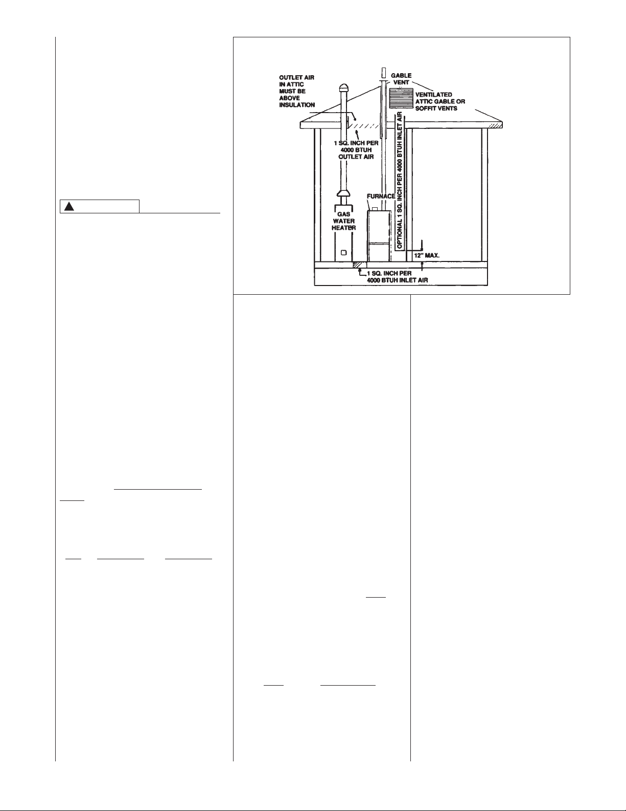
FIGURE 8
AIR FROM ATTIC/CRAWL SPACE
EXAMPLE 2.
FURNACE LOCATED IN A CONFINED
SPACE
A confined space (any space smaller
than shown above as “unconfined”)
must have openings into the space
which are located in accordance with
the requirements set forth in the following subsections A and B. Size the openings by how they are connected to the
heated area or to the outside, and by
the input of all appliances in the space.
If confined space is within a building
with tight construction, combustion air
must be taken from outdoors or area
freely communicating with the outdoors.
A. USING INDOOR AIR FOR COM-
BUSTION, ALL OF THE MODELS
IMPORTANT: Air should not be taken
from a heated space with a fireplace,
exhaust fan or other device that may
produce a negative pressure.
If combustion air is taken from the heat-
ed area, the openings must each
have at least 100 square inches of
free area. Each opening must have
at least one square inch of free area
for each 1,000 Btuh of total input in
the space. Here are some examples
of typical openings required.
Btuh Free Area
Input Each Opening
100,000 100 Square Inches
AIR INTAKE PIPE CONNECTION
(RGPE UPFLOW/HORIZONTAL
ONLY)
A double-elbow may be installed
to top inlet air opening, BUT IS
NOT REQUIRED.This will help to
prevent accidental blockage of
the intake opening. Reference
Figure 9 for proper elbow diameter.
NOTE: Inlet is specifically designed
to prevent material from being pulled
into furnace. If elbows are not used,
the intake opening must be kept
clean and free of debris.
It is also acceptable to run the
condensate drain (or refrigerant)
line access over the air intake
hole as long as a 1" minimum
clearance is maintained.
B. USING OUTDOOR AIR FOR
COMBUSTION, ALL OF THE
MODELS
IMPORTANT: Never take com-
bustion air from an attic space
that is equipped with power
ventilation.
The confined space must communicate with the outdoors
according to Methods 1 and 2.
The minimum air opening dimension shall not be less than 3 inches. When using ducts, they shall
be of the same cross-sectional
area as the free area of the openings to which they connect.
13
Page 14
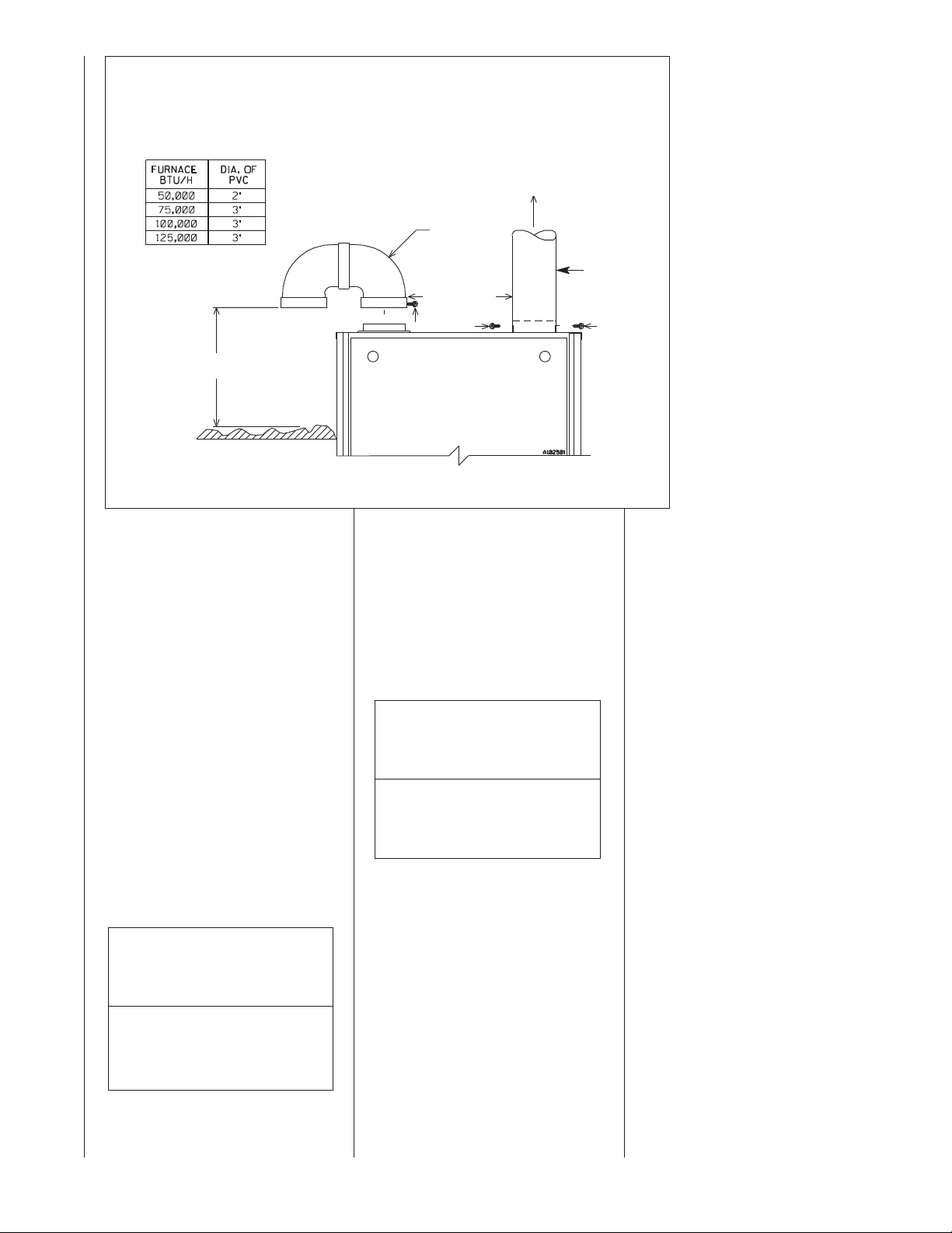
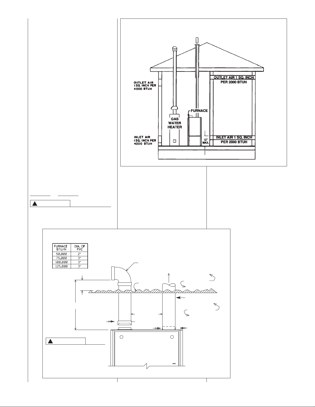
FIGURE 9
COMBUSTION AIR FITTING – NON-ATTIC COMBUSTION AIR PULL, RGPE ONLY
ATTACH OPTIONAL DOUBLE ELBOW TO TOP INLET AIR
OPENING TO PREVENT ACCIDENTALBLOCKAGE OF
INTAKE OPENING. THIS IS NOT A REQUIREMENT. (SEE
PREVIOUS PAGE.) SINGLE ELBOW IS ALLOWED BUT
MAY NOT PREVENT DEBRIS FROM BEING DROPPED
INTO THE FURNACE.
EXHAUST
PVC
DOUBLE
ELBOW
6" MININUM
CLEARANCE
#8 SCREWS
6" MIN.
GROUND OR
SHELF SURFACE
NOTE: PREDRILL HOLES FOR SCREWS TO PREVENT CRACKING.
METALFLUE
PIPE ONLY
#8 SCREWS
B: Method 1
Provide two permanent openings,
one located within 12 inches of the
top and one located within 12 inches
of the bottom of the enclosure. Each
opening shall communicate directly,
or by ducts, with the outdoors or
spaces (crawl or attic) that freely
communicate with the outdoors.
a. Where directly communicating
with the outdoors or where communicating to the outdoors
through VERTICAL DUCTS, each
opening shall have a minimum
free area of 1 square inch for
each 4000 BTUH of total appliance input rating in the enclosure.
Here are typical duct sizes:
VERTICAL OUTDOOR AIR
OPENING DIMENSIONS
BTUH Free Area Round
Input Each Opening Pipe Size
50,000 12.50 sq. inches 4”
75,000 18.75 sq. inches 5”
100,000 25.00 sq. inches 6”
125,000 31.25 sq. inches 7”
b. Where communicating with out-
doors through HORIZONTAL
DUCTS, each opening shall have
a minimum free area of 1 square
inch for each 2000 BTUH of total
input rating for all equipment in
the enclosure. Here are typical
duct sizes:
HORIZONTAL OUTDOOR AIR
OPENING DIMENSIONS
BTUH Free Area Round
Input Each Opening Pipe Size
50,000 25.00 sq. inches 6”
75,000 37.50 sq. inches 7”
100,000 50.00 sq. inches 8”
125,000 62.50 sq. inches 9”
B: Method 2
One permanent opening, located within
12 inches of the top of the enclosure,
shall be permitted where the equipment
has clearances of at least 1 inch from
the sides and back and 6 inches from
the front of the appliance. The opening
shall directly communicate with the outdoors or communicate through a vertical or horizontal duct to the outdoors or
spaces (crawl or attic) that freely communicate with the outdoors and have a
minimum free area of:
a. One square inch for each 3000
BTUH of the total input rating of
all equipment located in the
enclosure, AND
b. Not less than the sum of the
areas of all vent connectors in the
confined space.
IMPORTANT: If the furnace is in a
location with an exhaust fan, there
must be sufficient ventilation to prevent the exhaust fan from creating a
negative pressure in the room.
Combustion air openings must NOT
BE RESTRICTED in any manner.
CONSULT LOCAL CODES FOR
SPECIAL REQUIREMENTS.
14
Page 15
B: Method 3, RGPE only
For the optimum in quiet operation, attic
air may be brought directly to the furnace.
IMPORTANT: In applications using
Method 3 for combustion air, the attic
must be ventilated by gable or soffit
vents. See Figure 8.
It is not required to provide any permanent openings as described in
Method 1
!
or Method 2.
CAUTION
COMBUSTION AIR INTAKES CANNOT BE TERMINATED OUTSIDE.
DOING SO CAN CAUSE IMPROPER
FIGURE 10
OUTSIDE AIR USING A HORIZONTAL INLET & OUTLET
OPERATION OF THE FURNACE
If attic combustion air is used, the inlet
air opening at the furnace must be protected from accidental blockage. Install
a 90° elbow pointing horizontally at the
top of inlet air pipe. See Figure 11
(maximum of 2, 22
1
⁄2°, 45° or 90°
elbows, allowed).
NOTE: Maximum length of pipe that
may be used for combustion air is
10 feet with two elbows. Lengths of
more than 10 feet can result in nuisance pressure switch trips.
FIGURE 11
COMBUSTION AIR FITTING – OPTIONAL ATTIC COMBUSTION AIR PULL, RGPE ONLY
ATTACH A 90° ELBOW TO TOP INLET AIR
OPENING TO PREVENT ACCIDENTALBLOCKAGE
OF INTAKE OPENING.
PVC
ELBOW
EXHAUST
ATTIC SPACE
METALFLUE PIPE ONLY
INDOOR SPACE
10 FT. MAX.
!
CAUTION
12" MIN. FROM
TOP OF INSULATION
INCLUDING
HORIZONTALDIRECTION
#8 SCREW
INSULATION
6" MINIMUM
CLEARANCE
PVC
COUPLER
USE OF SHEET METAL
AIR INTAKE PIPE
INSTEAD OF PVC MAY
RESULT IN NOISE ISSUES.
NOTE: PREDRILL HOLES FOR SCREWS TO PREVENT CRACKING.
#8 SCREWS
15
Page 16
VENTING
GENERAL INFORMATION
The furnace must be vented in accordance with these instructions, National
Fuel Gas Code, ANSI Z223.1 and/or
the Natural Gas Installation Code, CSAB149.1 & .2 and requirements or codes
of the local utility or other authority having jurisdiction.
!
WARNING
DEVICES ATTACHED TOTHE FLUE
OR VENT FOR THE PURPOSE OF
REDUCING HEAT LOSS UP THE
CHIMNEY HAVE NOT BEEN TESTED
AND HAVE NOT BEEN INCLUDED IN
THE DESIGN CERTIFICATION OF
THIS FURNACE. WE, THE MANUFACTURER, CANNOT AND WILL NOT BE
RESPONSIBLE FOR INJURY OR
DAMAGE CAUSED BYTHE USE OF
SUCH UNTESTED AND/OR UNCERTIFIED DEVICES, ACCESSORIES OR
COMPONENTS.
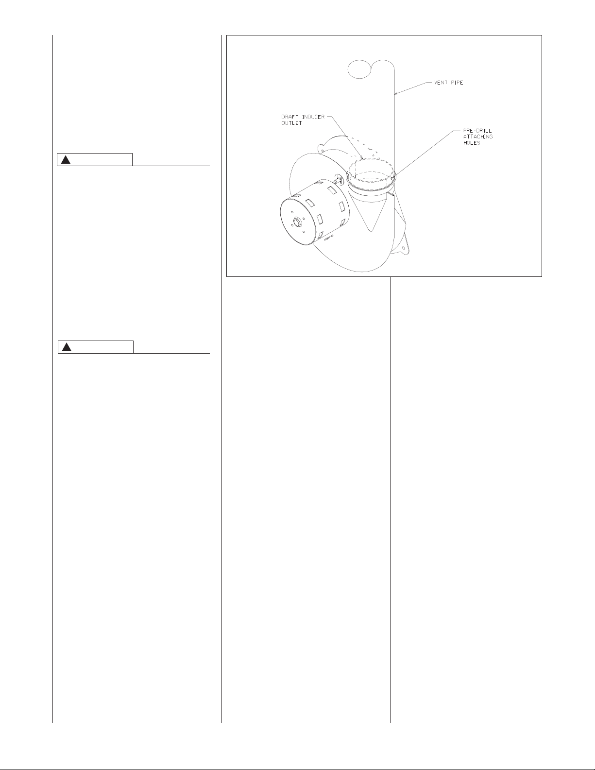
DRAFT INDUCER
!
WARNING
VENT PIPE ATTACHING HOLES
MUST BE PREDRILLED IN THE
DRAFT INDUCER COLLAR TO PREVENT DAMAGINGTHE INDUCER.
DRILL 1/8” DIAMETER HOLES
THROUGHTHE VENT PIPE AND
COLLAR AND USE #8 SCREWS TO
ATTACH. SEE FIGURE 12. FAILURE
TO FOLLOWTHIS WARNING CAN
CAUSE RECIRCULATION OF FLUE
PRODUCTS CAUSING CARBON
MONOXIDE POISONING RESULTING
IN PERSONAL INJURY OR DEATH.
FIGURE 12
ATTACHINGTO DRAFT INDUCER COLLAR
FURNACE CATEGORY
INFORMATION
This furnace is shipped as a Category I
type induced draft furnace. A Category
I furnace operates with a nonpositive
vent pressure and has a vent gas temperature at least 140°F above the dew
point of the vent gases. A Category I
type may be a draft hood equipped furnace or have a fan assisted combustion
system (induced draft). The inducer is
used to pull flue products through the
combustion chamber and as they leave
the furnace, most of the energy has
been dissipated. The buoyant effect of
the flue gases provides venting to the
outdoors.
During the off cycle, the inducer is off
and there is very little flow through the
vent, cooling the vent. During the on
cycle there is no dilution airflow, as with
a draft hood type furnace. Although the
vent heats up rapidly without dilution
air, the flue products contain more
water vapor, which results in a higher
dew point temperature. It is most
important that you follow the guidelines in these instructions to prevent the
possible formation of condensation in
the venting system.
As a Category I furnace it may be vented vertically with type B-1 vent pipe and
also may be common vented, as
described in these instructions.
A0991-01
IMPORTANT APPLICTION
NOTES
When the furnace is used as a
replacement, the existing vent system should be inspected to assure
that there are no obstructions, blockage, or any signs of corrosion and is
properly sized for use with this furnace.
NOTE: When the vent table permits
more than one diameter of pipe for a
connector or vent, the smallest permitted diameter must be used.
Vent pipe may be type “B-1,” either
rigid or suitable flexible construction
that carries a u.l. listing.
Common venting is allowed with
vertical B-1 vent systems, and lined
masonry chimneys. Follow the
National Fuel Gas Code, ANSI
Z223.1 and/or the Natural Gas
Installation Code, CSA-B149.1 & .2
for proper installation practices.
NOTE: Follow combustion air
instructions as outlined in this manual.
Single wall vent connectors to “B-1
vent or masonry chimneys” may be
used under the guidelines of the
National Fuel Gas Code, ANSI
Z223.1 and/or the Natural Gas
Installation Code, CSA-B149.1 & .2.
The entire length of the vent connector shall be readily accessible
for inspection, cleaning and
replacement.
16
Page 17

“B-1” VERTICAL VENTING
Type “B-1” vents must be installed in
accordance with the terms of their listings and the vent manufacturer’s
instructions.
“B-1” vents must be supported and
spaced in accordance with their listings
and the manufacturer’s instructions. All
vents must be supported to maintain
their minimum clearances from combustible material.
VERTICAL VENTING
Categorized
Input Size Required
50K 3”
75K *4”
100K *4”
125K *5”
*NOTE: All furnaces have a 3” vent connection as shipped from the factory. A 3” to 4” or
3” to 5” vent transition is required on all but
the 50,000 BTUH models when vertically
vented or common vented with metal vent
pipes. THE VENT TRANSITION CONNEC-
TION MUST BE MADE ATTHE FURNACE
VENT EXIT. It must originate with an adapter
if required, at the furnace flue collar and terminate either in a listed cap or roof assembly. When common venting, the vent connector size may differ from the above diameters depending on application. See ANSI
Z21.47-1993/CSA-2.3-M93 or latest edition
tables.
VERTICAL VENT SYSTEMS:
1. A gas vent shall terminate above the
roof surface with a listed cap or listed
roof assembly. Gas vents 12 inches
in size or smaller with listed caps
shall be permitted to be terminated in
accordance with Figure 13, provided
they are at least 8 feet from a vertical
wall or similar obstruction. All other
gas vents shall terminate not less
than 2 feet above the highest point
where they pass through the roof and
at least 2 feet higher than any portion
of a building within 10 feet.
2. A type B-1 gas vent shall terminate
at least 5 feet in vertical height above
the highest connected equipment
draft hood or flue collar.
3. Must rise
1
/4” per foot away from the
furnace on horizontal runs and be
supported with straps or hangers so
it has no sags or dips. Supports at 4
foot intervals and at all elbows are
recommended.
4. The vent connector must be mechanically fastened to the outlet collar of
the furnace with at least (2) sheet
metal screws except vent connectors
that are B-1 material. These shall be
assembled in accordance with the
manufacturer’s instructions. See
Figure 12.
Furnace Vent
FIGURE 13
TYPICAL VENTING WITH “B-1”VENT
5. Any angle greater than 45 degrees
from the vertical is considered horizontal. The total horizontal distance
of a vent plus the horizontal vent
connector serving draft-hood
equipped appliances shall not be
greater than 75 percent of the vertical height of the vent.
NOTE: Refer to the National Fuel Gas
Code, ANSI Z223.1 and/or the Natural
Gas Installation Code,
CSA-B149.1 & .2.
Single appliance venting of a fan assisted furnace into a tile-lined masonry
chimney is prohibited. The chimney
must be lined with either Type B vent or
with a listed, single wall, metal lining
system. Reference National Fuel Gas
Code, ANSI Z223.1 and/or the Natural
Gas Installation Code, CSA-B149.1 &
.2. See Figure 14 for typical B-1 vent
chase.
!
WARNING
DO NOT CONNECT THIS FURNACETO A CHIMNEY USED TO
VENT A SOLID FUEL APPLIANCE
(WOOD OR COAL).VENTING
WITH A SOLID FUEL APPLIANCE
CAN LEAD TO IMPROPER FUNCTIONING OF THE UNIT, AND DUE
TO SOOTING,THE POSSIBILITY
OF FIRE RESULTING IN PROPERTY DAMAGE, PERSONAL INJURY
OR DEATH.
SPECIAL VENT SYSTEMS
(SVS)
IMPORTANT: It is THE FURNACE
MANUFACTURER’s position now
that new
pipe used in a category III vent
application, including Selkirk’s
Selvent™ II HTPV product, should
cease immediately.
installations of any HTPV
17
Page 18
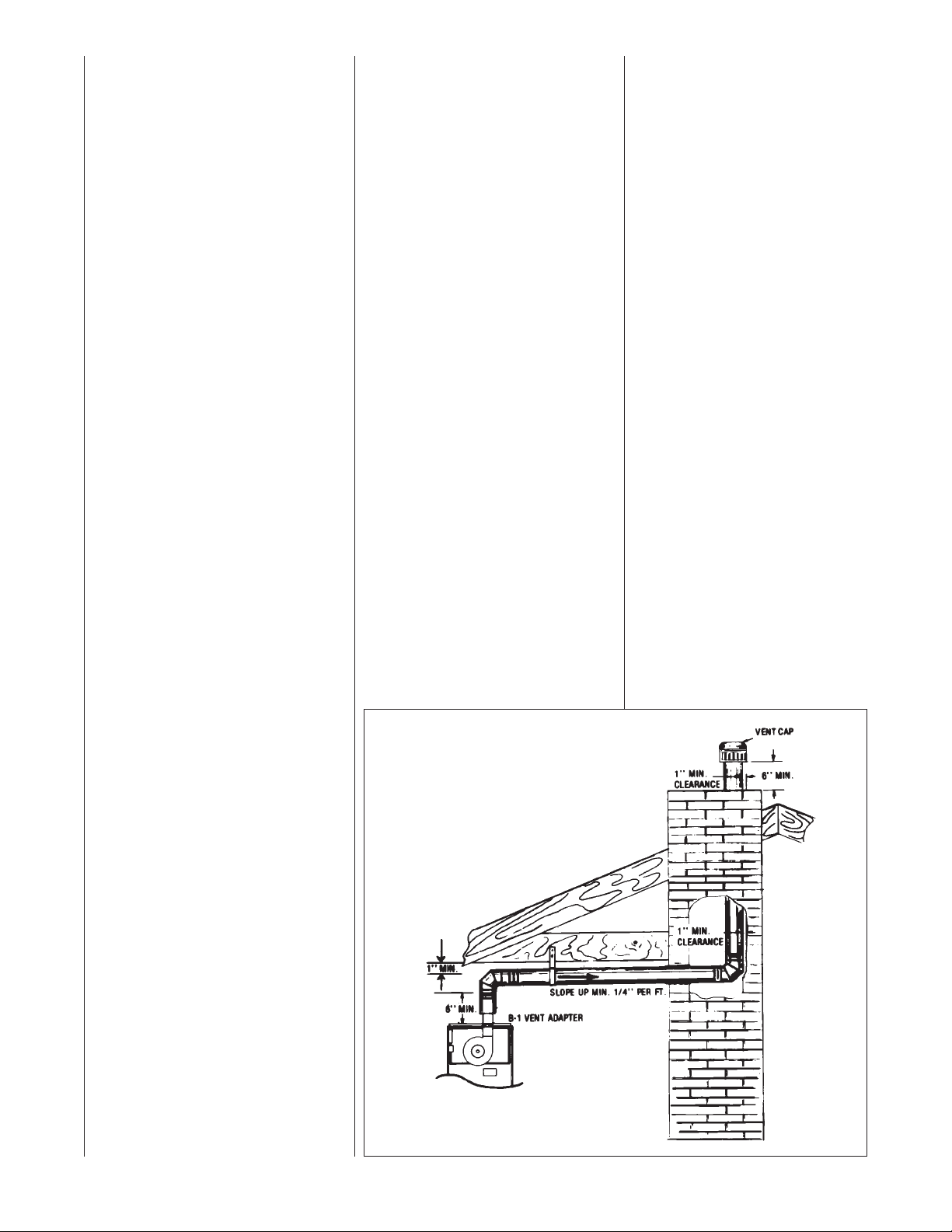
POWER VENT SYSTEMS
When vertical venting is not possible,
the only acceptable method for horizontal venting is with the use of Tjernlund
model GPAK-1TR or Field Controls
models SWG-4R power venter. Type B
vent pipe and fittings must be used.
Common venting is not permitted
All application and installation
instructions supplied with the power
venter must be followed.
Please address all questions regarding
power venter installation, agency listings and furnace model compatibility to:
Tjernlund Products, Inc.
(800) 255-4208 or (612) 426-2993
Field Controls L.L.C.
(800) 742-8368 or (919) 522-0214
RXGW-B01 CHIMNEY
ADAPTER
IMPORTANT: CHIMNEY ADAPTER IS
CERTIFIED FOR USE ON UPFLOW
(RGPE) ONLY.
This appliance is CSA certified for use
with RXGW-B01 Chimney Adapter.
Refer to Kit Installation Instructions
92-101682-01.
EXISTING VENT SYSTEMS
IMPORTANT RETROFIT
VENTING INSTRUCTIONS
If this furnace is a replacement installation, ALWAYS INSPECT the existing
vent system to be sure there are no
obstructions, blockages, or signs of corrosion.
When the existing furnace is removed
from a venting system serving other
appliances, the venting is likely to be
too large to properly vent the remaining
attached appliances.
The following steps shall be followed
with each appliance that remains connected to the common venting system,
while the other appliances that remain
connected to the common venting systems are not in operation.
NOTE:When the vent table permits
more than one diameter of pipe for a
connector or vent, the smallest permitted diameter must be used.
1. Seal any unused openings in the
common venting system.
2. Visually inspect the venting system
for proper size and horizontal pitch
and determine that there is no blockage, restriction, leakage, corrosion or
other deficiencies which could cause
an unsafe condition.
3. Insofar as is practical, close all building doors, windows and all doors
between the space where the appliances remaining connected to the
common venting system are located.
Turn on clothes dryers and any
appliance not connected to the
common venting system. Turn on
any exhaust fans, such as range
hoods and bathroom exhausts, so
they will operate at maximum
speed. Do not operate a summer
exhaust fan. Close fireplace
dampers.
4. Follow the lighting instructions.
Place the appliance being
inspected into operation. Adjust
the thermostat so the appliance
will operate continuously.
5. Test for spillage at the draft hood
relief opening after 5 minutes of
main burner operation. Use the
flame of a match or candle, or
smoke from a cigarette, cigar, or
pipe.
6. After it has been determined that
each appliance that remains connected to the common venting
system properly vents (when tested as outlined above) return
doors, windows, exhaust fans,
fireplace dampers and any other
gas-burning appliance to their
previous conditions of use.
7. If improper venting is observed
during any of the above tests, the
common venting system must be
resized. Refer to National Fuel
Gas Code, ANSI Z223.1 and/or
the Natural Gas Installation Code,
CSA-B149.1 & .2.
FIGURE 14
DEDICATED VENTING THROUGH
CHIMNEY WITH “B-1”VENT
18
Page 19
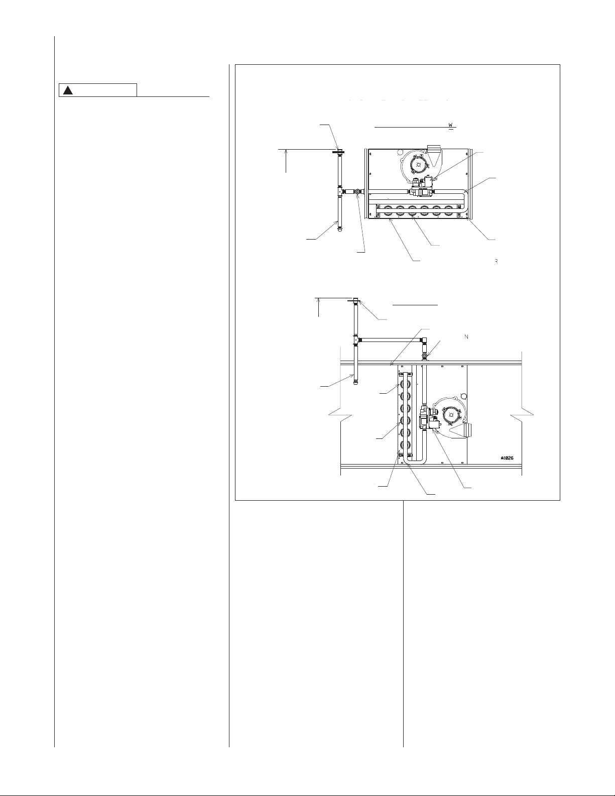
GAS SUPPLY AND PIPING
GAS SUPPLY
!
WARNING
THIS FURNACE IS EQUIPPED ATTHE
FACTORY FOR USE ON NATURAL
GAS ONLY. CONVERSIONTO LP GAS
REQUIRES A SPECIAL KIT AVAILABLE FROMTHE DISTRIBUTOR.
FAILURETO USE THE PROPER CONVERSION KIT CAN CAUSE FIRE,
CARBON MONOXIDE POISONING,
EXPLOSION, PROPERTY DAMAGE,
PERSONAL INJURY OR DEATH.
See the conversion kit index supplied
with the furnace.This index identifies
the proper LP Gas Conversion Kit
required for each particular furnace.
IMPORTANT: Any additions, changes or
conversions required for the furnace to
satisfactorily meet the application should
be made by a qualified installer, service
agency or the gas supplier, using factory-specified or approved parts. In the
commonwealth of Massachusetts,
installation must be performed by a
licensed plumber or gas fitter for appropriate fuel.
IMPORTANT: Connect this furnace only
to gas supplied by a commercial utility.
IMPORTANT: A U.L. recognized
fuel gas and CO detector(s) are recommended in all applications,
and their installation should be in accordance with the detector manufacturer’s
recommendations and/or local laws,
rules, regulations or customs.
FIGURE 15
GAS PIPING INSTALLATION
MANUAL GAS VALVE
(IN CLOSED POSITION)
4 TO 5 FEET
ABOVE FLOOR
REQ'D BY SOME
UTILITIES
DRIP LEG
4 TO 5 FEET
ABOVE FLOOR
REQ'D BY SOME
UTILITIES
DRIP LEG
GAS PIPE INSTALLATION
UPFLOW & DOWNFLOW
UNION
HORIZONTAL
MANUAL GAS VALVE (IN CLOSED POSITION)
FLAME
SENSOR
BURNERS
BURNERS
FLAME SENSOR
DUCT
UNION
GAS VALVE
MANIFOLD
DIRECT SPARK
IGNITOR
GAS PIPING (SEE FIGURE 15)
Install the gas piping according to all
local codes, state codes and regulations
of the utility company, whichever holds
jurisdiction.
If possible, run a separate gas supply
line directly from the meter to the furnace. Consult the local gas company for
the location of the manual main shut-off
valve.The gas line and manual gas
valve must be adequate in size to
prevent undue pressure drop and
never smaller than the pipe size to
the combination gas valve on the furnace. Refer to Table 2 for the recom-
mended pipe size for natural gas and
Table 3 for LP gas pipe sizes.
IMPORTANT: It is permissible to run
flexible gas connector inside the unit to
a piece of black pipe. If local codes
DIRECT SPARK IGNITOR
allow the use of a flexible gas appliance
connector, always use a new listed connector. Do not use a connector which
has previously serviced another gas
appliance.Massachusetts law limits flexible gas connectors to a maximum of
36”.
Install a ground joint union outside
the cabinet to easily remove the control valve assembly. Install a manual
shut-off valve in the gas line outside
the cabinet. The valve should be readi-
ly accessible to turn the gas supply on
or off. Install a drip leg in the gas supply
line as close to the furnace as possible.
Always use a pipe compound resistant
to the action of liquefied petroleum
gases on all threaded connections.
MANIFOLD
GAS VALVE
IMPORTANT: When making gas
pipe connections, use a back-up
wrench to prevent any twisting of the
control assembly and gas valve.Do
not overtighten the connection.
Any strains on the gas valve can
change the position of the gas orifices in the burners. This can cause
erratic furnace operation.
IMPORTANT: ENSURE that the fur-
nace gas control valve not be subjected to high gas line supply pressures.
DISCONNECT the furnace and its
individual shut-off valve from the gas
supply piping during any pressure
testing that exceeds 1/2 PSIG (14”
W.C.) (3.48 kPa).
19
Page 20
GAS PRESSURE
IMPORTANT: Natural gas supply pressure should operate between 5" to
10.5”w.c. LP gas supply pressure
should be 11” to 13” w.c. This pressure
must be maintained with all other
gas-fired appliances in operation.
NOTE: Do not exceed a gas pressure
of 13” w.c.
WARNING
!
ELEVATIONS ABOVE 2000 FT
REQUIRETHATTHE FURNACE INPUT
RATING BE ADJUSTED ANDTHAT
THE SIZE OFTHE BURNER ORIFICES BE RE-CALCULATED BASED
ON ELEVATION AND GAS HEATING
VALUE.THE BURNER ORIFICES MAY
(OR MAY NOT) NEED TO BE
CHANGED.SEE THE SECTION
TITLED“HIGH ALTITUDE INSTALLATIONS” OF THIS BOOK FOR
INSTRUCTIONS.
WARNING
!
NEVER PURGE A GAS LINE INTO
THE COMBUSTION CHAMBER.
NEVER USE MATCHES, FLAME OR
ANY IGNITION SOURCE FOR
CHECKING LEAKAGE.FAILURETO
FOLLOWTHIS WARNING CAN
CAUSE AN EXPLOSION OR FIRE
RESULTING IN PROPERTY DAMAGE,
PERSONAL INJURY OR DEATH.
To check for gas leakage, use an
approved chloride-free soap and water
solution, or other approved method.
LP CONVERSION
NOTE: For installation, see specific LP
kit installation instructions. Orifice must
be ordered for the correct elevation.
NOTE:Order the correct LP conversion
kit from the local distributor. Furnace
conversion to LP gas must be performed by a qualified technician.
More information found in the high altitude and orifice section.
NOx MODELS
When converting furnaces equipped
with NOx inserts to LP gas, remove
the NOx insert assemblies. Steps for
removal are listed below:
1. Turn off all electrical power and
the gas supply to the furnace.
2. Remove the burner door from
the furnace.
3. Remove the igniter assembly –
handle with care.
4. Remove the two screws attaching the NOx insert retainer
brackets to the center panel.
Pull the retainer rod.
5. Put the two screws back into the
holes in the center panel.
6. Re-install the igniter and burner
assemblies.
7. Replace burner door.
8. Turn on electrical power and
gas supply to the unit.
NOTE:Some NOx models may have
one less NOx insert.
20
Page 21
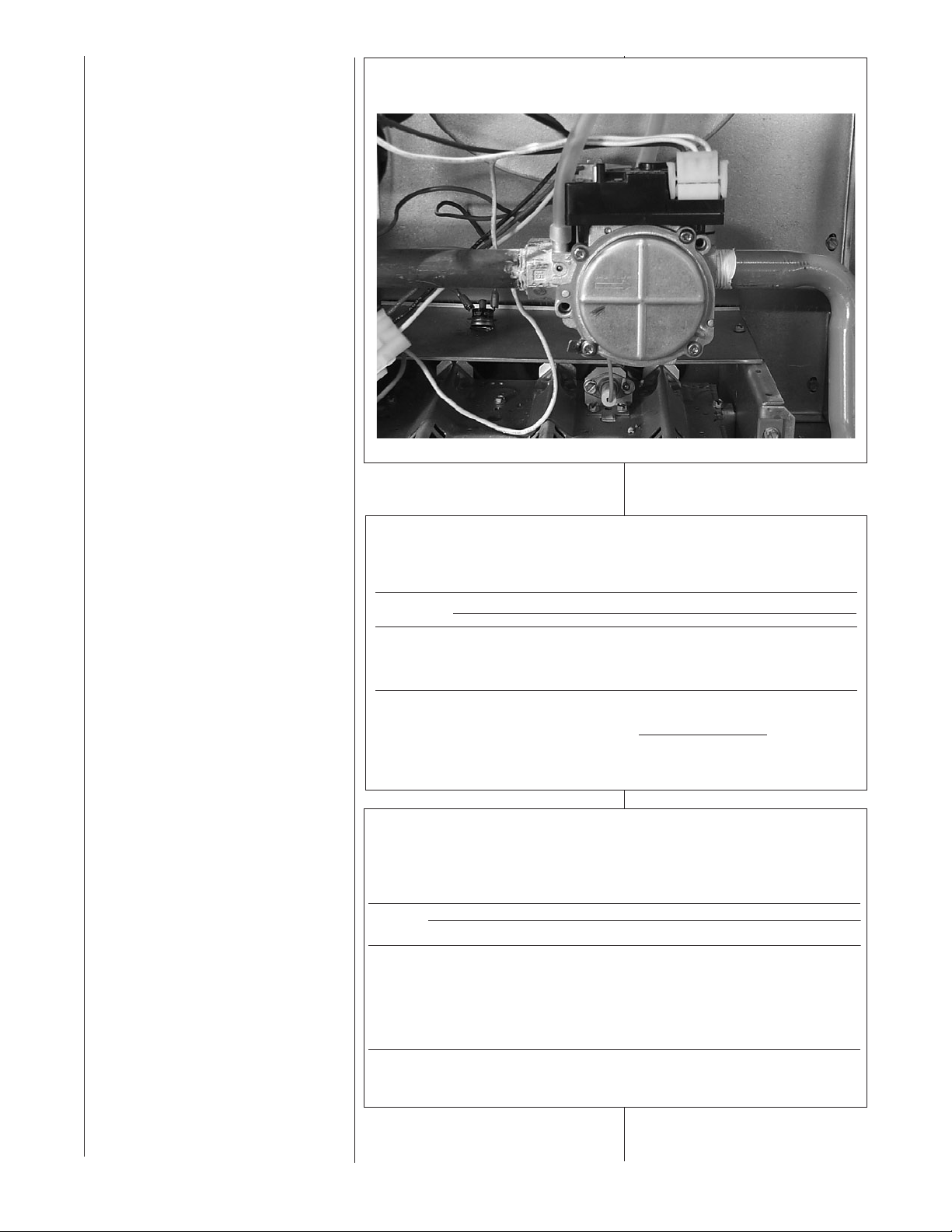
SETTING GAS PRESSURE
Maximum capacity of pipe in thousands of BTU per hour of undiluted liquefied petroleum gases (at 11 inches water
column inlet pressure).
(Based on a Pressure Drop of 0.5 Inch Water Column)
Nominal Length of Pipe, Feet
Iron Pipe
Size, Inches 10 20 30 40 50 60 70 80 90100125 150
1/2 275 189 152 129 114 103 96 89 83 78 69 63
3/4 567 393315 267 237 217 196 182 173 162 146 132
11,071 732 590504 448 409 378 346 322 307 275 252
1-1/4 2,205 1,496 1,212 1,039913 834 771 724 677 630567 511
1-1/2 3,307 2,299 1,858 1,559 1,417 1,275 1,1811,086 1,023 976 866
787
2 6,221 4,331 3,465 2,9922,646 2,394 2,205 2,047 1,9211,811 1,606 1,496
Example (LP): Input BTU requirement of unit, 150,000
Equivalent length of pipe, 60 ft. = 3/4" IPS required.
The maximum gas supply pressure to
the furnace should be 10.5” w.c. natural gas, or 13” w.c. LP gas. The minimum supply gas pressure to the gas
valve should be 5" w.c. natural gas or
11" w.c. LP gas. A properly calibrated
manometer is required for accurate gas
pressure measurements.
Supply Gas Pressure Measurement.
A line pressure tap is on the inlet side
of the gas valve.
1. With gas shut off to the furnace at
the manual gas valve outside the
unit, remove the input pressure
tap plug.
2. Connect a U-Tube manometer to
the pressure tap.
3. Turn on the gas supply and operate the furnace and all other gasfired units on the same gas line as
the furnace.
4. Adjust the line gas pressure to
supply:
A. 5” - 10.5” w.c. for natural gas.
B. 11” - 13” w.c. for LP gas.
5. Shut off the gas at the manual gas
valve and remove the
U-Tube manometer.
6. Replace the pressure tap plug.
7. Turn gas on, and check for leaks.
NATURAL GAS:
If the supply gas line pressure is above
the operating range, install an in-line
gas regulator to the furnace. If supply
gas line pressure is below the operating range, either remove any restrictions in the gas supply piping or
enlarge the gas pipe. See Table 2.
LP GAS:
If the supply gas line pressure is above
the operating range, have the LP supplier reduce the line pressure at the
regulator. If supply gas line pressure is
below operating range, have the LP
supplier adjust the line pressure at the
regulator. See Table 3.
NOTE: Depending on the amount of
LP vapor and the outdoor ambient temperature, the LP storage tank may
require supplemental heat to maintain
proper pressure levels. Ensure LP storage tank does not drop below 15%
capacity during heating season.
FIGURE 16
TYPICAL HOSE CONNECTION TO LINE PRESSURETAP
TABLE 2
NATURALGAS PIPE CAPACITYTABLE (CU. FT./HR.)
Capacity of gas pipe of different diameters and lengths in cu. ft. per hr. with pressure drop of 0.3 in. and specific
gravity of 0.60 (natural gas).
Nominal Length of Pipe, Feet
Iron Pipe
Size, Inches 10 20 30 40 50 60 70 80
1/2 132 92 73 63 56 50 46 43
3/4 278 190 152 130 115 105 96 90
1 520 350 285 245 215 195 180 170
1-1/4 1,050 730 590 500 440 400 370 350
1-1/2 1,600 1,100 890 760 670 610 560 530
After the length of pipe has been determined, select the pipe size which will provide the minimum cubic feet per
hour required for the gas input rating of the furnace. By formula:
Cu. Ft. Per Hr. Required =
The gas input of the furnace is marked on the furnace rating plate. The heating value of the gas (BTU/FT3) may be
determined by consulting the local natural gas utility or the LP gas supplier.
Gas Input of Furnace (BTU/HR)
Heating Value of Gas (BTU/FT3)
TABLE 3
LP GAS PIPE CAPACITYTABLE (CU.FT./HR.)
21
Page 22
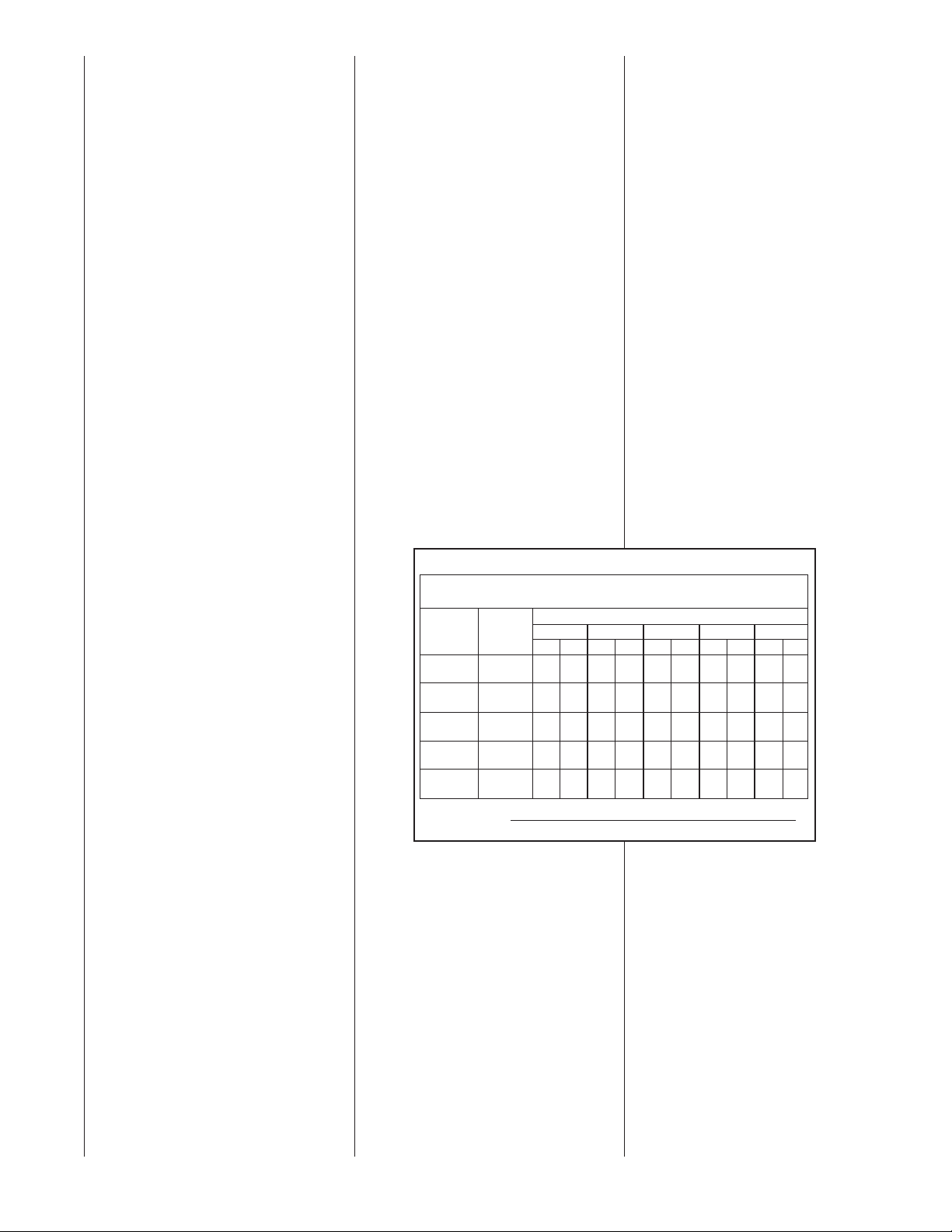
ADJUSTING OR CHECKING
FURNACE INPUT
NATURAL GAS:
The maximum gas supply pressure to
the furnace should be 10.5” W.C. for
natural gas. The minimum gas supply
pressure for purposes of input adjustment to the furnace should be 5” W.C.
A properly calibrated manometer or
gauge is required for accurate gas
pressure readings.
1. When adjusting the furnace input,
the high fire input should be
checked. The high fire manifold pressure should be 3.5' W.C. Follow
these steps to be sure the furnace is
high fire mode:
a. With a single stage thermostat,
the furnace runs for 12 minutes on
low fire before shifting to high fire.
To be certain that it is on high fire,
jump terminals “W” and “W2” on
the control board in the blower
compartment.
b. With a two stage thermostat, set
the thermostat to its highest setting to keep the furnace operating
in the high fire mode.
2. To adust high fire manifold pressure,
remove the adjustment cover screw
on the outlet end of the gas valve
and turn the adjustment screw clockwise to increase the pressure and
counterclockwise to reduce the pressure. Replace the cover screw
securely.
3. The low fire manifold pressure
should be 1.7" W.C. As mentioned
above, the furnace remains in the
low fire mode for 12 minutes upon a
heat call with a single stage thermostat. With a two stage thermostat,
disconnect the thermostat lead to the
“W2” terminal on the control board
and the furnace will remain in the low
fire mode. To adjust the pressure,
remove the regulator cover, on top of
the valve, and adjust as noted under
Step 2, above. After the adjustment
replace the screw cover securely.
NOTE: Use a 3/32⬙ allen wrench for
making the pressure adjustment.
LP GAS:
Furnaces for use on LP gas, the LP gas
supply pressure must be set between
11.0” and 13.0” W.C. by means of the
tank or branch supply regulators. The
furnace manifold pressure should be
set at 10” W.C. at the gas control valve.
For elevations up to 7,000 feet, rating
plate input ratings apply. For high altitudes (elevations 7,000 and over) and
for any necessary major changes in the
gas flow rate the orifice spud must be
changed.
TO CHANGE ORIFICE SPUDS:
1. Shut off the manual main gas valve
and remove the gas manifold.
2. Replace the orifice spuds.
3. Reassemble in reverse order.
4. Turn the gas supply back on and
check for leaks.
5. Check for proper operation and set
to proper manifold pressure.
TABLE 4
METER TIME IN MINUTES AND SECONDS FOR NORMAL
INPUT RATING OF FURNACES EQUIPPED FOR NATURAL OR LP GAS
INPUT
BTU/HR
50,000
75,000
100,000
125,000
150,000
Input BTU/HR =
METER
CU. FT.
SIZE
ONE 15112 1 15 1 18 3 20
TEN 10 50 12 00 12 30 13 12 30 00
ONE 0 44 0 48 0 50 0 53 20
TEN 7 12 80819 8 48 20 0
ONE 0 33 0 36 0 38 0 40 1 30
TEN 5 24 60615 6 36 15 0
ONE 0 26 0 29 0 30 0 32 1 12
TEN 4 19 4 48 50517 12 0
ONE 0 31 0 24 0 25 0 26 10
TEN 3 36 40410 4 20 10 0
Heating Value of Gas (BTU/Ft3) x 3600 x correction factor
Time in Seconds (for 1 cu.ft.) of Gas
HEATING VALUE OF GAS BTU PER CU. FT.
900 1000 1040 1100 2500
MIN. SEC. MIN. SEC. MIN. SEC. MIN. SEC. MIN. SEC.
Check of input is important to prevent over firing of the furnace
beyond its design-rated input.
NEVER SET INPUT ABOVE THAT
SHOWN ON THE RATING PLATE.
TO CHECK FURNACE INPUT:
1. Make certain that all other gas
appliances are shut off, with the
exception of pilot burners.
2. Start the furnace
3. Time the meter to measure the
time required to burn one cubic
foot of gas.
4. Use Table 4 to determine input
rate.
22
Page 23
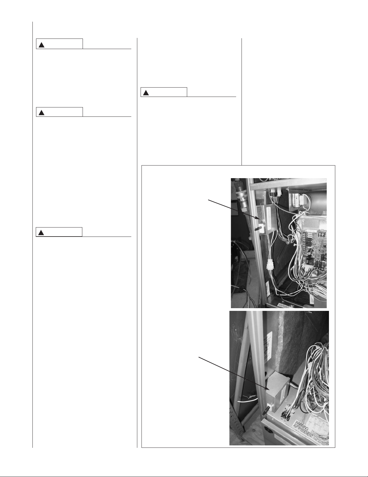
ELECTRICAL WIRING
WARNING
!
TURN OFF ELECTRIC POWER AT
FUSE BOX OR SERVICE PANEL
BEFORE MAKING ANY ELECTRICAL CONNECTIONS. FAILURETO
DO SO CAN CAUSE ELECTRICAL
SHOCK RESULTING IN PERSONAL INJURY OR DEATH.
WARNING
!
THE CABINET MUST HAVE AN
UNINTERRUPTED GROUND
ACCORDINGTO THE LATEST
EDITION OF THE NATIONAL
ELECTRICAL CODE, ANSI/
NFPA70-, OR IN CANADA,THE
CANADIAN ELECTRICAL CODE,
CSA-C22.1 OR LOCAL CODES
THAT APPLY. A GROUND SCREW
IS PROVIDED IN THE JUNCTION
BOX. FAILURE TO PROPERLY
CONNECTTHE GROUNDWIRE
CAN CAUSE ELECTRICAL
SHOCK RESULTING IN PERSONAL INJURY OR DEATH.
ate wiring diagramlocated on the inside
cover of the furnacecontrol box and in
these instructions.
NOTE:The electrical junction box may
be moved to the right sideif necessary. A
knockout is provided.Seal the opposite
holewith plugprovided.
WARNING
!
L1TERMINAL AND NEUTRALTERMINAL POLARITY MUST BE OBSERVED
WHENMAKINGFIELD CONNECTIONS
TOTHE FURNACE. FAILURETO DO
SOWILL EXPOSE LIVEWIRING IN
THE BLOWER COMPARTMENTWHEN
THE DOOR IS REMOVED.TOUCHING
THESE LIVE CIRCUITS COULD
RESULT IN PERMANENT INJURY OR
DEATH FROMELECTRICALSHOCK.
FIGURE 17
JUNCTION BOX LOCATION
UPFLOW/HORIZONTAL
Make all electrical connections in
accordance with the latest edition of
the National Electrical Code
ANSI/NFPA70 – or in Canada, the
Canadian Electrical Code Part 1CSA Standard C22.1 and local codes
having jurisdiction.
These may be obtained from:
National Fire Protection
Association, Inc.
Batterymarch Park
Quincy, MA 02269
Canadian StandardsAssociation
178 Rexdale Boulevard
Rexdale, Ontario, Canada M9W 1R3
WARNING
!
THIS FURNACE IS EQUIPPED
WITH A BLOWER DOOR SAFETY
SWITCH. DO NOT DISABLETHIS
SWITCH. FAILURETO FOLLOW
THISWARNING CAN RESULT IN
ELECTRICAL SHOCK, PERSONAL INJURY OR DEATH.
IMPORTANT: The furnace must be
installed so that the electrical components are protected from water.
A grounding wire is provided to connect
to the incoming grounding wire from
line power. The furnace must be permanently grounded in accordance with all
national and local codes.
Before proceeding with the electrical
connections, be certain that the service
panel voltage, frequency and phase corresponds to that specified on the furnace rating plate. Maximum over-current
protection is 15 amperes.
Use a separate,fused branch electrical
circuitcontaininga properly sizedfuse or
circuitbreaker. Connect this circuitdirectly
fromthe main switchbox to an electrical
disconnect that is readily accessible and
locatedwithin arm’s reach (2 ft.)of the
furnace. Connect fromthe electrical disconnectto the junction boxon the left
sideof the furnace, inside the blower
compartment. See Figure 17.For the
proper connection,refer to the appropri-
DOWNFLOW
23
Page 24

ELECTRICAL CHECKS
Line Power Check
The furnace must have a nominal 115
volt power supply for proper operation. If there is not a consistent power
supply, contact a licensed electrician
to correct the problem.
1. With the blower compartment door
off, manually hold the push button
door switch in.
2. Call for heat at the thermostat.
3. With the unit operating, use a voltmeter to measure the voltage from
any 120 VAC terminal to any neutral connection.
4. The voltage should be a nominal
115 volts (acceptable 105120VAC).
This test should be made with the unit
in full operation.
Polarity Check
If line & neutral are reversed, a fault
code (26) will be displayed at the furnace seven segment display (SSD)
and at the communicating thermostat
active fault display screen (communicating systems only).
Proper line voltage polarity, or phasing, is a must for this furnace to operate. Use a volt meter to make this
check.
1. With the blower compartment door
off, manually hold the push button
door switch in.
2. Use a voltmeter to measure the
voltage from any 120 VAC terminal
to any bare metal ground on the
furnace.
3. The voltage should be a nominal
115 volts (acceptable 105120VAC).
4. Use a voltmeter to measure the
voltage from any neutral terminal
to the bare metal ground on the
furnace.
5. The voltage should be less than
1.0 VAC.
6. If the voltage from any 120 VAC
terminal to ground is less than 1.0
VAC volts and the voltage from a
neutral to ground is a nominal 115
volts, the polarity is reversed.
7. To correct the problem, either
reverse the hot and neutral wires
to the furnace or have a licensed
electrician check the building
wiring.
ControlVoltage Check
1. With the blower compartment door
off, manually hold the push button
door switch in.
2. Call for heat at the thermostat.
(Does not include communicating
thermostats.)
3. With the unit operating, use a voltmeter to measure the voltage from
control voltage terminal “W” to terminal “C” on the furnacecontrol
board.
4. The voltage should be a nominal 24
volts (Acceptable 18-30 VAC).
This test should be made with the unit
in full operation.
24
Page 25
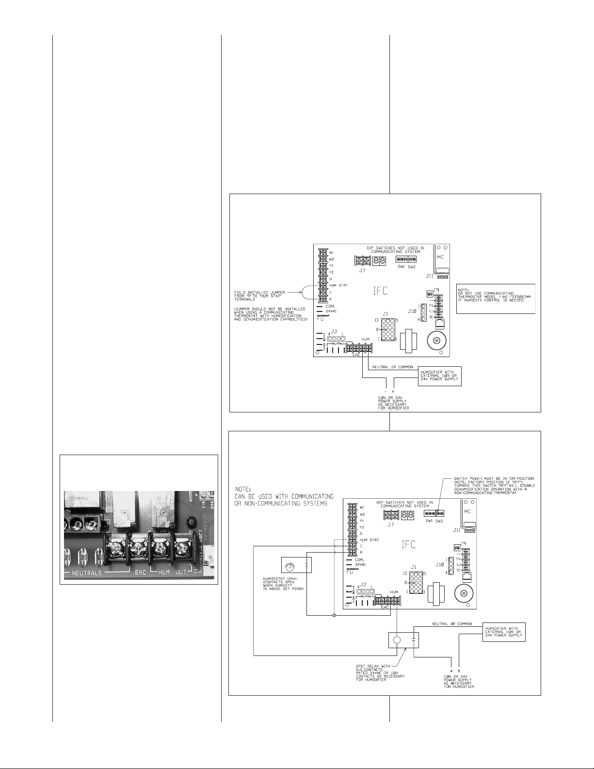
ACCESSORIES
FIELD-INSTALLED
OPTION ACCESSORIES
TWINNING: Most installations of (-)GPE/
(-)GLE furnaces cannot be twinned.
However, a few exceptions exist for
installations with some commercial
evaporator coils. Consult the installation
instructions of the coil to see if the furnace(s) can be twinned. If so, a twinning
kit will be required and the part number
for the kit can be found in the installation
instructions for the coil.
ELECTRONIC AIR CLEANER
Line voltage power is supplied from the
screw terminal “EAC”, see Figure 18,
and a line voltageneutral screw terminal
on the control board. This will power the
electronic air cleaner whenever the
blower is operating and delivering the
recommended minimum CFM. The 50
and 75 KBTU models, which are capable of a maximum delivery of 1200 CFM,
will operate the electronic air cleaner at
500 CFM and above. The 100 and 120
KBTU models, which are capable of a
maximum delivery of 2000 CFM, will
operate the electronic air cleaner at 800
CFM and above. These limits are set to
prevent excessive production of ozone
at the lower airflows of the furnaceand
are based on average requirements of
commercially available electronic air
cleaners.
Continuous fan speeds are selectable
and some lower fan speeds may not
deliver enough airflow to operate an
electronic air cleaner. The IFC determines the minimum airflow necessary to
operate an electronic air cleaner and will
not turn on the electronic air cleaner
unless the airflow is high enough for the
EAC.
FIGURE 18
EAC AND HUMIDIFIER TERMINALS ON FURNACE CONTROL (IFC)
HUMIDIFICATION AND DEHUMIDIFICATION
HUMIDIFIER – The humidifier contacts
(labeled “HUM OUT”) are “dry” contacts
on the I.F.C. This means that the terminals are connected directly to the contacts of a board-mounted relay. The
coil of the relay is controlled by the
microprocessor of the IFC. The coil is
engaged roughly any time the heat
speed blower is engaged and (1)
24VAC is present on the thermostat terminal of the IFC labeled “HUM STAT” or
(2) a communicating thermostat with
humidification and dehumidification
capability is installed with call for
humidification present.
FIGURE 19
WIRING FOR OPTIONAL HUMIDIFICATION (AND DEHUMIDIFICATION WITH COMMUNICATING
THERMOSTAT) WITH OPTIONAL HUMIDIFIER AND NO HUMIDISTAT (HUMIDIFICATION ACTIVE
DURING ANY HEAT CALL) (FOR USE WITH COMMUNICATING AND NON-COMMUNICATING
THERMOSTATS)
FIGURE 20
WIRING FOR OPTIONAL DEHUMIDIFICATIONWITH HUMIDIFICATION (WITH OPTIONAL
HUMIDISTAT AND HUMIDIFIER)
NOTE: CAN BE USED WITH COMMUNICATING OR
NON-COMMUNICATING SYSTEMS
An optional 24VAC humidistat can
be installed as shown in Figures 19
thru 54 (II thru IV). With the optional
humidistat, two separate conditions
must be met before humidification
can begin 1). There must be a call
for heat and the blower must be
engaged and 2.) The humidistat
must determine that there is a need
for humidification.
Note: Dipswitch SW2-1 (labeled
“ODD”) enables (“ON”) or disables
(“OFF”) dehumidification operation.
However, it has no affect on humidification operation. If this switch is
set to the “ON” position and no
humidistat is installed, the cooling
25
Page 26
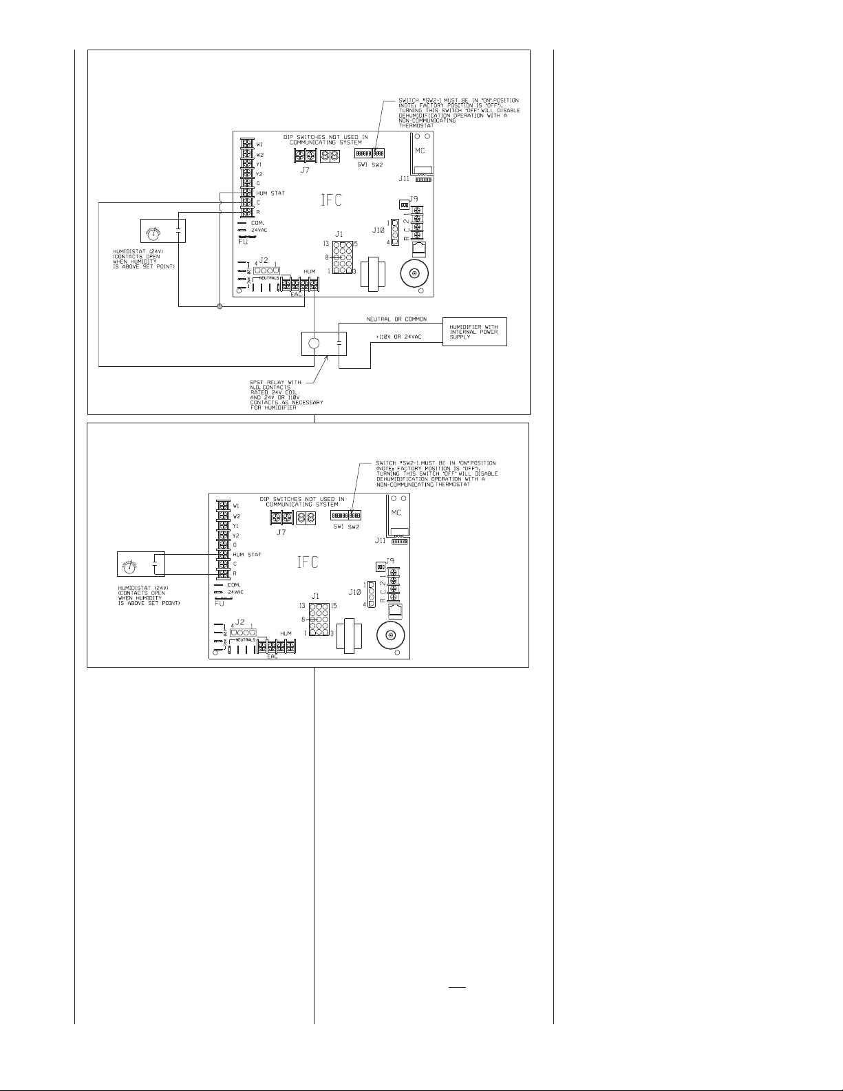
FIGURE 21
WIRING FOR OPTIONAL DEHUMIDIFICATION OPERATION AND HUMIDIFICATION WITH
OPTIONAL HUMIDIFIER (HUMIDIFIER WITH INTERNAL POWER SUPPLY) (FOR USE WITH
NON-COMMUNICATINGTHERMOSTATS)
FIGURE 22
HUMIDISTAT USEDTO CONTROL DEHUMIDIFICATION IN COOLING ONLY (NO HUMIDIFIER)
(FOR USE WITH NON-COMMUNICATINGTHERMOSTATS)
airflow will be permanently reduced by
approximately 15% giving less than
optimal performance and possibly causing problems. It is not recommended to
leave this switch in the “ON” position
without a humidistat installed.
Control of dehumidification in cooling
and/or humidification in heating can be
done with a variety of methods depending on whether there is a communicating thermostat or a humidistat available
and depending on the type of operation
desired.
With systems configured with communicating thermostats and condensers,
dehumidification is controlled by the
condenser and is not affected by the
position of dipswitch SW2-1 or the voltage (or lack of voltage) at the thermostat terminal labeled “HUM STAT”.
To determine which wiring diagram and
method to use, select from the following
configurations:
A. HUMIDIFICATION CONTROL ONLY
WITH NO DEHUMIDIFICATION
(REQUIRES OPTIONAL HUMIDIFIER).
A1. WITH COMMUNICATING
THERMOSTAT
Humidifier control is included
with the (-)HC-TST412MDMS
(modulating, non-communicating) and (-)HC-TST550CMMS
(full-color communicating)
model thermostats. However, it
is not included with the (-)HCTST501CMMS model communicating thermostat. The latter
thermostat should not be used
if humidification control is
required. To wire the furnace
for humidification control using
the former thermostat, refer to
the wiring diagram in Figure
19(I). Be sure not
to install the
jumper between “R” and “HUM
STAT” on the furnace control. Installing this jumper
will operate the humidifier
any time there is a heat call.
Without the jumper, the
humidification call from the
thermostat must be active
and a heat call must be present with the blower running.
A2. WITH NON-COMMUNICAT-
ING THERMOSTAT
A2-1 CONTINOUS HUMID-
IFIER OPERATION
DURING HEATING.
For continuous humidifier operation during
heating, refer to
Figure 19 (I) and
make sure to install
the jumper between
the thermostat terminals labeled “R” and
“HUM STAT”. A separate humidistat is not
required for this configuration and the
humidifier will turn on
whenever there is a
call for heat and the
blower is running.
A2-2 CONTROLED
HUMIDIFIER OPERATION USING A
HUMIDISTAT
(REQUIRES OPTIONAL HUMIDISTAT).
Controlled humidification can be accomplished using a
humidistat as shown
in Figures 20 (II) or 21
(III). These figures
show installation of a
humidifier with external and internal power
supplies respectively.
Dehumidification operation will be disabled if
the dipswitch SW2-1
is in the “OFF” position. If this switch is in
the “ON” position,
dehumidification control will be active.
B. DEHUMIDIFICATION CONTROL
WITH NO HUMIDIFICATION
B1. For communicating ther-
mostats listed with this furnace, dehumidification is
controlled automatically
when selected at the thermostat and additional wiring
is not necessary. The actual
airflow demand (reduced for
dehumidification) is requested of the furnace by the
condenser.
26
Page 27
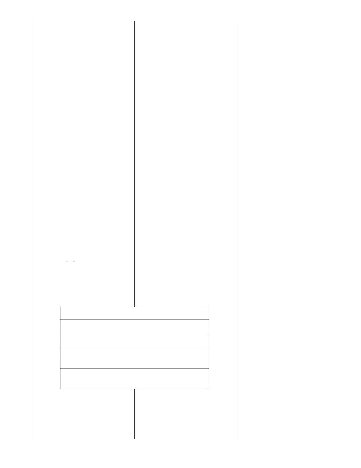
B2. WITH NON-COMMUNICATING
THERMOSTAT (REQUIRES
OPTIONAL HUMIDISTAT).
Control of dehumidification only
(no humidification) can be
accomplished by installing an
optional humidistat as shown in
Figure 22 (IV). The dipswitch
SW2-1 must be set to the “ON”
position. If this switch is not
turned “ON”, dehumidification
operation will not take place.
Further, if this switch is “ON”
and no humidistat is installed,
airflow in cooling will be permanently reduced by approximately 15%.
C. HUMIDIFICATION AND DEHUMIFI-
CATION CONTROL
(REQUIRES OPTIONAL HUMIDIFIER).
C1. WITH COMMUNICATING
THERMOSTAT
Humidifier control is included
with the (-)HC-TST412MDMS
(modulating, non-communicating) and (-)HC-TST550CMMS
(full-color communicating)
model thermostats. However, it
is not included with the (-)HCTST501CMMS model communicating thermostat. Do not
purchase the latter thermostat if
humidification control is
required. To wire the furnace
for humidification and dehumidification control using the former
thermostat, refer to the wiring
diagram in Figure 19 (I). Be
sure not
between “R” and “HUM STAT”
on the furnace control.
Installing this jumper will operate the humidifier any time
to install the jumper
THERMOSTAT AND ACCESSORIES FOR THERMOSTAT
Programmable Communicating:
(-)HC-TST501CMMS
Full-Color, Programmable Communicating:
(-)HC-TST550CMMS
Remote Sensor:
(For Thermostats Above Only)
F1451378
Thermostat Wall Plate ForThermostat HC-TST501CMMS
Above Only:
F61-2600
there is a heat call and dehumidification will never take
place when in cooling. Without
the jumper, a humidification call
from the thermostat must be
active and a heat call must be
present with the blower running
for the “HUM OUT” relay contacts to close.
C2. WITH NON-COMMUNICATING
THERMOSTAT (REQUIRES
OPTIONAL HUMIDISTAT.)
For non-communicating thermostats, an optional humidistat
must be installed. Controlled
humidification and dehumidification can be accomplished
using a humidistat as shown in
Figures 20 (II) or 21 (III).
These figures show installation
of a humidifier with external and
internal power supplies respectively. Dehumidification operation will be disabled if the dipswitch SW2-1 is in the “OFF”
position. If this switch is in the
“ON” position, dehumidification
control will be active.
OTHER ACCESSORIES
AVAILABLE
FOSSIL FUEL KIT (non-communicat-
ing systems only)
Use of a heat pump with the two stage
furnace requires a heat pump thermostat
used in conjunction with the fossil fuel
kit. For proper operation use the following procedures:
a. With the RXPF-F01 kit, connectthe
thermostat “E” terminal, one side of
the plenum switch, and the black wire
from the fossil fuel kit to “W2” on the
IFC.
b. For the RXPF-F02 kit, connect
“W” on the fossil fuel kit interface
wiring board to “W2” on the IFC.
Regardless of which fossil fuel kit is
used, when activated, the two stage
furnace follows the sequence of
operation for a single stage thermostat.
➢ IMPORTANT: ALWAYS FOLLOW
THE MANUFACTURER’S FOSSIL
FUEL KIT INSTRUCTIONS.
TWINNING: Most installations of
(-)GPE and (-)GLE furnaces cannot
be twinned. However, a few exceptions exist for installations with some
commercial evaporator coils. Consult
the installation instructions of the coil
to see if the furnace can be twinned.
If so, a twinning kit will be required
and the part number for the kit can
be found in the installation instructions for the coil.
RXGW-B01 CHIMNEY
ADAPTER
IMPORTANT: Chimney adapter is
certified for use on upflow only.
This appliance is CSA certified for
use with RXGW-B01 chimney
adapter. Refer to kit installation
instructions
92-101682-01.
TYPICAL WIRING FOR
SELECT ACCESSORIES
FOR COMMUNICATING
RESIDENTIAL SYSTEMS
The Rheem Serial Communicating
(CC2) system allows accessories to
be connected to shut down the system in the event of a fault. Typical
devices that can be connected are
the drain overflow switch, smoke
detector and freeze protection
switch. There are two methods of
connecting the switch to the system
depending on the device configuration normally closed or normally
open. The blower can run during a
fault or the blower can shut off during a fault depending on how the
system is connected. Please refer to
local and/or state codes for installing
these devices. The following operation applies only when BOTH the
condenser and thermostat are serial
communicating devices. If the condenser is non-communicating (traditional, legacy 24VAC controlled) this
diagram is not valid.
27
Page 28
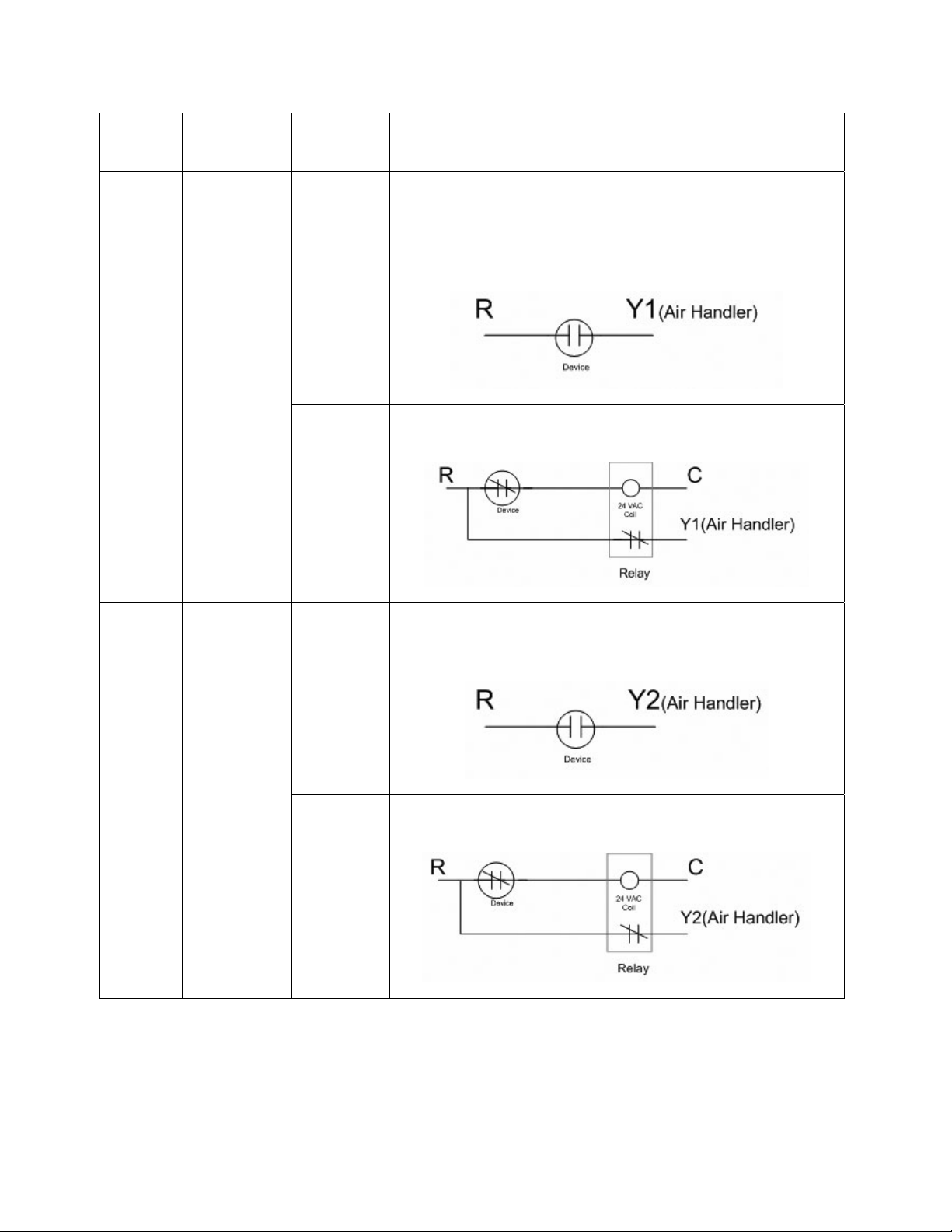
METHOD BLOWER
ACTIVATION
CONTACTS WIRING CONFIGURATION
NORMALLY
OPEN
When 24 VAC is applied to Y1 at the furnace control in a
communicating system a SYSTEM BUSY message appears on
the thermostat. When the SYSTEM BUSY message appears the
outdoor unit will shut down and the indoor unit will continue
to run at first stage cooling airflow.
A
BLOWER
RUNS
(Y1)
NORMALLY
CLOSED
If the device does not have normally open contacts an
additional relay must be used for proper system operation.
NORMALLY
OPEN
When the device is connected to Y2 and a fault occurs the
blower will shut down. The Y2 input can still be used with
normally open or normally closed contacts.
B
BLOWER
DOES NOT
RUN
(Y2)
NORMALLY
CLOSED
If the device does not have normally open contacts an
additional relay must be used for proper system operation.
OPERATION WITH SELECTED ACCESSORIES
28
Page 29
80+ HIGH ALTITUDE
THE MANIFOLD PRESSURE OF THIS APPLIANCE HAS
BEEN FIELD ADJUSTED TO OBTAIN THE CORRECT
INPUT RATING FOR INSTALLATION AT ALTITUDES
BETWEEN 2,000 FEET AND 4,500 FEET ELEVATION.
LA PRESSION DU DISTRIBUTEUR D'ALIMENTATION
DE CET APPAREIL A ÉTÉ AJUSTÉ SUR LES LIEUX AFIN
D'OBTENIR LA BONNE PUISSANCE D'ENTRÉE POUR
UNE INSTALLATION ENTRE 2000 ET 4500 PIEDS
D'ALTITUDE.
92-24399-01-01
INSTRUCTIONS (TABLE 13)
!
CAUTION
INSTALLATION OFTHIS FURNACE
AT ALTITUDES ABOVE 2000 FT (610
m) SHALL BE IN ACCORDANCE
WITH LOCAL CODES, OR IN THE
ABSENCE OF LOCAL CODES,THE
NATIONAL FUEL GAS CODE, ANSI
Z223.1/NFPA 54 OR NATIONAL STANDARD OF CANADA, NATURAL GAS
AND PROPANE INSTALLATION
CODE, CAN B149.1.
Furnaces can be ordered from the factory already converted for high altitude
elevations. The factory option for high
altitude elevations would be ordered as
a 278 option (example: a 75k BTU
upflow furnace which is factory converted for high altitude elevations would
have the model number (-)GPE07EAMKR). These factory converted
furnaces come with pressure switches
for high-altitude elevations already
attached. Also, different burner orifices
are installed at the factory which are
one drill size smaller (#43 DMS) than
standard (-)GPE/(-)GLE gas furnaces
(#42 DMS). The smaller orifice is
installed to accommodate for average
heating values expected in most high
altitude areas and a required 4% per
thousand feet reduction in input as
specified by the National Fuel Gas
Code (NFGC). Specific orifices should
always
be recalculated for all high altitude installations as outlined below.
Orifices should be changed, if necessary, based on gas heating value and
elevation.
34" 80 Plus furnaces installed above
2,000 ft. require the furnace to be derated 4% per thousand feet.
IMPORTANT: Factory installed orifices
are calculated and sized based on a
sea level Natural Gas heating value of
1075 BTU per cubic ft.
NOTE:Orifices are available through
your local distributor.
Reference Tables 11, 12 and 13 for
appropriate orifice sizing.
NOTE:Keep any parts removed during
LP conversion procedure stored with the
product literature for future use.
The following are examples of orifice
sizing using the National Fuel Gas Code
Appendix F:
Example: 900 BTU/ft
Natural Gas Heating Value
I/H = Q
25000 / 900 = 27.78 ft
I = Sea Level input (per burner): 25000
H = Sea Level Heating Value: 900
Q = 27.78 ft
3
Natural Gas per hour.
From Table F.1 of National Fuel Gas
Code Handbook, 2002 (3.5ⴖ w.c. col-
umn).
Orifice required at Seal Level: #40
From Table F.4 of National Fuel Gas
Code Handbook, 2002
Orifice required at 5000 ft. elevation (4%
de-rate per thousand ft): #42
3
Regional
3
Orifice required at 8000 ft. elevation (4%
de-rate per thousand ft.): #44
TABLE 11
LP GAS
Example: 1050 BTU/ft3 Regional
Natural Gas Heating Value
I / H = Q
25000 / 1050 = 23.81ft
3
I = Sea Level input (per burner): 25000
H = Sea Level Heating Value: 1050
Q = 23.81 ft
3
Natural Gas per hour.
From Table F.1 of Natural Fuel Gas
Code Handbook, 2002 (3.5⬙ w.c. col-
umn).
Orifice required at Sea Level: #43
From Table F.4 of National Fuel Gas
Code Handbook, 2002
Orifice required at 5000 ft. elevation (4%
de-rate per thousand ft.): #45
Orifice required at 8000 ft elevation (4%
de-rate per thousand ft): #47
LP GAS (TABLE 11)
LP Gas is a manufactured gas that has
consistent heating value across most
regions.
The NFGC guidelines are used with the
following exception:
The recommended LP Gas high altitude
orifice selections differ slightly in that the
NFGC LP orifice chart, as they are not
accurate for Rheem products. The
National Fuel Gas Code LP orifices are
based on an 11" of water column pressure at the orifice, which differs from
products that use 10" of water column
at the orifice. This difference requires a
deviation from the NFGC orifice size
recommendations. The Sea Level input
Altitude burner) 25000 Size
0 to 2000 ft. 25000 #54
2000ⴕ-3000ⴕ 24000 #54
3000ⴕ-4000ⴕ 23000 #54
4000ⴕ-5000ⴕ 22000 #54
5000ⴕ-6000ⴕ 21000 #54
6000ⴕ-7000ⴕ 20000 #54
7000ⴕ-8000ⴕ 19000 #55
8000ⴕ-9000ⴕ 18000 #55
9000ⴕ-10000ⴕ 17000 #55
sand ft. and the orifice size must be
selected based on the reduced input
in Table 11.
ORIFICE ORDERING
INFORMATION
Orifice sizes are selected by adding
the 2-digit drill size required in the
orifice part number. Drill sizes available are 39 through 64; metric sizes
available 1.10mm (-90) and 1.15mm
(-91):
Orifice Part Number 62-22175-(drill
size)
Example 1:
# 60 drill size orifice required
Part # 62-22175-60
Example 2:
1.15mm drill size orifice required
Part # 62-22175-91
should still be reduced by 4% per thou-
TABLE 12
ALTERNATE METHOD FOR CANADIAN HIGH-ALTITUDE DERATE
NATURAL GAS LP GAS
ORIFICE
ALTITUDE
0’ - 2000’
2001’ - 4500’
INPUT
50,000
75,000
100,000
125,000
150,000
45,000
67,500
90,000
112,500
135,000
OUTPUT
40,000
60,000
80,000
100,000
120,000
36,000
54,000
72,000
90,000
108,000
SIZE
#42
#42
MANIFOLD
PRESSURE
3.5” W.C.
2.9” W.C.
ALTITUDE
0’ - 2000’
2001’ - 4500’
FIGURE 23
MANIFOLD PRESSURE-CHANGE LABEL
INPUT
50,000
75,000
100,000
125,000
150,000
45,000
67,500
90,000
112,500
135,000
Input (per Orifice
ORIFICE
OUTPUT
40,000
60,000
80,000
100,000
120,000
36,000
54,000
72,000
90,000
108,000
SIZE
#54
#54
MANIFOLD
PRESSURE
10” W.C.
8.1” W.C.
29
Page 30

NATURALGAS QUICK REFERENCE CHART FOR ORIFICE SELECTION, AT 3.5" W.C.AND APPROXIMATE FINAL FIRING RATES
ELEVATION CHART (NFG recommended orifice based on 4% derate for each 1000 foot of elevation, based on the intersection of the
Heat
80 Plus
Cubic
Sea Level
orifice required at Sea Level and the elevation required below)
Value at
Foot at
0-999 1000-1999 2000-2999 3000-3999 4000-4999 5000-5999 6000-6999 7000-7999 8000-8999 9000-9999
25,000
3.5" W.C.
25,000 24,000 23,000 22,000 21,000 20,000 19,000 18,000 17,000 16,000
30
TABLE 13
37 30.63 816 37 37 38 39 39 40 41 42 42 43
38 29.25 855 38 38 39 40 41 41 42 42 43 43
39 28.2 887 39 39 40 41 41 42 42 43 43 44
40 27.03 925 40 40 41 42 42 42 43 43 44 44
41 25.98 962 41 41 42 42 42 43 43 44 44 45
Size
Orifice
80 Plus Models with 25,000 Btu's per Burner
SUPPLEMENTAL ORIFICE SIZE CHART
Sea Level
42 24.95 1002 42 42 42 43 43 43 44 44 45 46
43 22.39 1117 43 43 44 44 44 45 45 46 47 47
44 21.01 1190 44 44 45 45 45 46 47 47 48 48
Final Firing Rate per Burner
NOTE:
All calculations are performed by using the first three columns of information only. Before beginning any calculations, determine the individual burner Btu size
and heating value at Sea Level for the installation site. Each value shown in the Heat Value column is per burner at 3.5" W.C.
Heat Value at Sea Level, for the location of the installation, is available from the Natural Gas Supplier to that site. Orifices for all altitudes are based on Sea Level values.
Divide the individual burner capacity (25,000 for 80 plus) by the Heat Value for the site to determine the Cubic Foot value at Sea Level, or divide burner capacity by the
Cubic Foot value for the Heat Value. Once you have either the Cubic Foot Value or the Heat Value you can estimate the Sea Level orifice for the site. To select the corre-
sponding high altitude orifice, locate the site elevation on the chart above and the orifice required at Sea Level from your calculation in the first column. The correct high
altitude orifice that must be installed in each individual burner is the intersection of these two points on the chart above.
Page 31

ALTERNATE METHOD FOR
CANADIAN
HIGH-ALTITUDE
DERATE
In Canada, unless an orifice change is
specifically mandated by local codes, an
alternate method of altitude deration
through a reduction in manifold pressure
is acceptable as described in Table 12.
This information is based on a heating
value of 1000 BTU per cubic feet of natural gas, and 2500 BTU per cubic feet
of LP gas.
IMPORTANT: Actual input rates must
be measured onsite with manifold pressure adjustment to ensure that an actual
10% reduction in input rate is achieved.
Once this field adjustment has been
made, the label shown in Figure 23
must be affixed in a conspicuous location on the front of the furnace cabinet.
NOTE: This label is supplied in the
information packet shipped with each
furnace.
AIR FLOW
The importance of proper air flow over
the heat exchanger cannot be over
emphasized.
!
CAUTION
IT IS IMPORTANT THAT EACH DUCT
SYSTEM BE SIZED AND INSTALLED
FORTHE SPECIFIC APPLICATION BY
PROPERLY APPLYINGTHE APPROPRIATE INDUSTRY ACCEPTED STANDARD. IF LESS THAN MINIMUM
STANDARDS ARE APPLIED,THE
EQUIPMENT USER COULD EXPECT
TO EXPERIENCE HIGHER UTILITY
BILLS,MAJOR COMPONENT FAILURE,VARYING DEGREES OF AIR
NOISE OR OTHER UNSATISFACTORY
ISSUES,OVERWHICHTHE MANUFACTURER HAS NO CONTROL.
One of the most common causes of heat
exchanger failure is overheating due to
low air flow.An air flow table is located
inside the blower door and on the following pages.
FIGURE 24
TEMPERATURE RISE MEASUREMENT
FIGURE 25
TYPICAL FURNACE NAME PLATE
AIR CONDITIONING DIVISION
FORT SMITH, ARKANSAS
ZONING SYSTEMS
The manufacturer does not currently
provide or support zoning.However,
zoning systems can be installed with the
system as long as the zoning equipment
manufacturers specificationsand installation instructions are met and followed.
The preferred zoning method is to use a
“bypass” system which is properly
installed for maximum efficiency. In
these systems, excess air is routed back
through the system to be used again –
this is opposed to a “dump” system in
which excess air is routed to a zone
where it is expected that the extra heat
or cooling would be least noticed.
If installed as a “bypass” system, the
installation must have an optional freeze
stat installed to preventthe coil from
icing with excess bypass cooling. Also, if
the zoning equipment manufacturerprovides a limit switch (usually provided by
31
Page 32

the zoning manufacturer), this limit must
be installed in the system to prevent the
furnace from overheating.
TEMPERATURE RISE CHECK
To determineif the air flow is correct,
make a temperature rise check.
1. Insert a thermometer in the supply
air duct as close to the furnace as
possible yet out of a direct line from
the heat exchanger. See Figure 24.
2. Insert a thermometer in the return
air duct as close to the furnace as
possible.
3. Operate the furnace.
4. When the thermometer in the supply air duct stops rising (approximately five minutes), subtract the
return air temperature from the supply air temperature. The difference
is the temperature rise.
5. Compare the measured temperature rise to the approved temperature rise range listed on the furnace
name plate. See product specification sheet and nameplate located
on furnace.
If the measured temperature rise is
above the approved range, either the air
flow is too low or the manifold pressure
needs to be adjusted. More air must be
moved by speeding up the blower, by
removing restrictions in the duct system,
or by adding more supply or return air
duct. If the measured temperature rise is
below the approved range, either the air
flow is too much or the manifold pressure needs to be adjusted. Use lower
speed tap on the multi-speed blower.
IMPORTANT: The measured temperature rise should be in the middle of the
range. See product specification sheet
and name plate located on furnace.
IMPORTANT: Some high-efficiency filters have a greater than normal resistance to airflow. This can adversely affect
furnace operation.BE SURETO CHECK
AIRFLOW if using any filter other than
factory-provided filter.
32
Page 33

INTEGRATED FURNACE CONTROL (I.F.C.)
(all must be on)
FIGURE 26
TWO-STAGE CLIMATE-TALK COMMUNICATING FURNACE CONTROL (RHEEM # 62-102784-01)
24 VACTHERMOSTAT
(TSTAT) INPUTS (J4 & J6)
24 VACTHERMOSTAT (TSTAT)
INPUTS (J4 & J6)
These connections are used with any
traditional 24VAC one-stage or twostage thermostat. Fully communicating
thermostats must be connected to the
COMM NETWORK CONNECTION
(see section titled
SSYYSSTTEEMMSS
details).
CCOOMMMMUUNNIICCAATTIINNGG
of this document for
22,, YY11,, YY22,, GG,, CC aanndd RR
WW11,, WW
traditional
nearly all HVAC equipment. Installation
of the thermostat to these connections
is straight-forward and simple.
thermostat inputs used in
are the
HHUUMM SSTTAATT
to connect the output of a humidistat
to the furnace control to control
humidification and/or dehumidification. Optional equipment is required
for these features. Please see the
section titled
DEHUMIDIFICATION
ment for more details.
– T
his terminal is used
HUMIDIFICTION AND
of this docu-
33
Page 34

SPECIAL CONFIGURATION –
COMMUNICATING THERMOSTAT
AND FURNACE WITH A NONCOMMUNICATING CONDENSER
YY11 aanndd YY22
used to connect directly to a non-communicating condenser when a communicating thermostat is installed to the
furnace but a non-communicating condenser is installed in the system. While
the optimum configuration is with a
communicating condenser connected
to the network, there may be installations where this is not desired. In
these cases, the thermostat will be
communicating with the furnace control
and the furnace control will energize
the condenser as necessary (the additional relays have been added to the
furnace control to allow this operation).
The thermostat connections labeled
“Y1” and “Y2” on the I.F.C. are normally
iinnppuuttss
the blower when they are energized.
However, in this configuration, these
(normally) inputs become
energize the condenser when a cooling
call has been sent from the communicating thermostat.
– These terminals may be
to the furnace control to turn on
oouuttppuuttss
to
When this configuration is desired, use
the wiring diagram in Figure 27 to connect the thermostat and condenser to
the furnace control. For single stage
condensers, a jumper must be installed
between Y1 & Y2 at the furnace control.
NOTE: A heat pump condenser cannot
be installed with this configuration.
There is no control for the reversing
valve.
24 VAC FROM TRANSFORMER
(XFORMER) CONNECTIONS
These inputs are used to connect
24VAC from the furnace transformer to
the furnace control (I.F.C.).
FUSE (F1)
A three-amp automotive-style (ATC
blade type) fuse is supplied on-board
the furnace control. This fuse should
provide protection from short-circuits on
the control board and associated 24
VAC wiring.
115 VAC TERMINALS
These terminals supply 115 VAC to
the furnace control from the input at
the junction box of the furnace.
Additionally, spare terminals are provided for use with electronic air
cleaners and other accessories as
needed (Check the voltage rating of
your equipment.)
INDUCED DRAFT MOTOR
(INDUCER) OUTPUT (J2)
This four-pin Mate-n-Lok style connector is black in color and provides
power to both the high and low
speed inducer outputs. This connector on the IFC has female sockets so that it can not be confused
with the four-pin connector used for
motor control (which has male pins).
For troubleshooting purposes, follow
the wiring diagram and troubleshooting flowchart supplied in this manual
and on the inside of the furnace
blower door. Additionally, the pin
designations for the connector are
specified below:
FIGURE 27
WIRING DIAGRAM – SPECIAL CONFIGURATION: COMMUNICATING THERMOSTAT AND FURNACE WITH NON-COMMUNICATING CONDENSER
34
Page 35

PPiinn 11
to Inducer High Speed Output.
PPiinn 22
PPiinn 33
PPiinn 44
Inducer Low Speed Output
to
not used.
is
Neutral.
to
NEUTRAL TERMINALS
These terminals connect 115VAC neutral to the furnace control from the input
at the junction box of the furnace.
Additionally, spare terminals are provided for use with electronic air cleaners,
humidifiers and other accessories as
needed (Check the voltage rating of
your equipment.)
ELECTRONIC AIR CLEANER
(E.A.C.) OUTPUT (J8)
This output is used to energize an electronic air cleaner. The output will provide 1.0 amp at 115 VAC. This output is
energized any time the blower motor is
above 40% of maximum airflow capacity. Airflow below this value is not considered to be enough for a typical electronic air cleaner to perform properly.
For 1/2HP motors – Electronic air cleaner is energized any time the blower is
above 480 CFM (1200 CFM x 0.4)
For 1 HP motors - Electronic air cleaner
is energized any time the blower is
above 800 CFM (2000 CFM x 0.4)
HUMIDIFIER OUTPUT (J8)
These outputs (two) are connected to
the contacts of a control-mounted relay.
In this sense, they are what are called
“dry” contacts. That is, they provide no
voltage, they are only used to close a
circuit. The contacts can be used to
close either a 24VAC or 115VAC circuit
either with a maximum of 1 amp current. Details about the humidifier outputs and wiring diagrams can be found
in the section titled
AND DEHUMIDIFICATION
ument.
HUMIDIFICATION
of this doc-
15-PIN MATE-N-LOK CONNECTOR (J1) (see Fig 28)
The 15-pin Mate-n-Lok style connector
provides connections for a variety of
inputs and outputs to the furnace control. For modulating furnaces with a
solenoid-controlled modulating gas
valve (HG or HH Fuel Codes) the 15pin connector provides power and control signals to the gas valve. Also, the
flame sense, pressure switches sense
and limits sense (Main Limit, MRLC
and HALC) are connected to the I.F.C.
through this connector. Reference the
wiring diagram for the furnace printed
in this document or on the inside of the
furnace blower door for pin assignments for troubleshooting.
For troubleshooting purposes, follow
the wiring diagram and troubleshooting flowchart supplied in this manual
and on the inside of the furnace
blower door. Additionally, the pin
designations for the connector are
specified below:
PPiinn 11
to F
lame Sense rod.
PPiinn 22
to
Overtemp Limit (MRLC)
Sense
PPiinn 33
PPiinn 44
PPiinn 55
PPiinn 66
PPiinn 77
PPiinn 88
PPiinn 99
PPiinn 11
PPiinn 1111
PPiinn 11
PPiinn 11
PPiinn 11
PPiinn 11
Main Limit (LC) Sense
to
24 VAC to Limit Sense
to
Circuits
VAC out to Auxiliary Limit
24
(HALC- Heat
Control)
1st stage gas valve solenoid
valve main
2nd stage gas valve solenoid
Low Pressure Switch
to
sense.
High Pressure Switch
to
sense.
00
to Low and High Pressure
Switch 2
to Aux Input sense
22
to Ground on furnace cabi-
net
33
not used on this control
44
not used on this control
55
gas valve 24VAC common
Assisted Limit
solenoid 24VAC.
4VAC
35
Page 36

FIGURE 28
15-PIN CONNECTOR; J1 WITH PIN DESIGNATIONS
COMMUNICATING ECM
MOTOR COMMUNICATIONS
(CONTROL) CONNECTION
(J10) (see Fig 28)
This connector sends and receives
messages to and from the blower motor
through a single peer-to-peer network.
The blower motor does not communicate on the same communications buss
as the furnace, condenser and thermostat. Further, a different communications protocol is used.
For troubleshooting purposes, follow
the wiring diagram and troubleshooting
flowchart supplied in this manual and
on the inside of the furnace blower
door. Additionally, the pin designations
for the connector are specified below:
PPiinn 11
to com
motor
PPiinn 22
motor
PPiinn 33
motor
PPiinn 44
motor
municating blower
connector Pin 1 (+V)
to communicating blower
connector Pin 2 (TX)
to communicating blower
connector Pin 3 (RX)
to communicating blower
connector Pin 4 (C)
36
Page 37

FIGURE 29
FOUR-PIN MOTOR CONTROL CONNECTION; J10 WITH PIN ASSIGNMENTS.
SPARK IGNITION TRANSFORMER (XFORMER) (T1)
The spark ignition transformer resides
on the furnace control (older generations of the modulating furnace have
the spark transformer mounted to a
separate ignition control). The transformer provides spark energy at
approximately 60 hz frequency and a
minimum of 12KV. The transformer can
be seen in Figure 29.
R-J11 CONNECTOR (J-11)
WARNING
!
DO NOT CONNECT A TELEPHONE
OR PHONE LINE TO THE CONNECTOR (JACK) AT POSITION J-11.
DOING SO COULD CAUSE
IRREPRABLE DAMAGE TO EITHER
THE FURNACE CONTROL (I.F.C.) OR
THE TELEPHONE (OR TELEPHONE
LINE) OR BOTH.
This connector is used to program the
furnace control at the factory. It can
also be used to connect a field service
diagnostic tool. Unfortunately, this tool
was not available at the time of this
publication but should be available in
the future. Otherwise, this connection
is not to be used in the field. It should
never be connected to a telephone line
or a telephone. Doing so could damage the furnace control or the telephone (or telephone lines) or both.
COMMUNICATIONS
NETWORK CONNECTION
These connections are used when
installing a communicating thermostat
specified for use with this furnace.
Further, normally, thermostat connections will not be made at the 24 V
Thermostat Inputs when using a communicating thermostat. (Except under
one special circumstance where a com-
municating thermostat and non-communicating condenser are used.
See Figure 27 and the section of
this document titled SPECIAL CON-
FIGURATION – COMMUNICATING
THERMOSTAT AND FURNACE
WITH A NON-COMMUNICATING
CONDENSER.)
The terminal labeled “1” on the furnace control connects directly to the
terminal labeled “1” on the thermostat and “1” on the condenser. The
remaining connections follow the
same pattern.
Follow the wiring diagram in Figure
27 for connections of the communications network.
COMMUNICATIONS
L.E.D.’s (Light Emitting
Diodes)
Note: The “RX” and “STAT”
L.E.D.’s will not operate unless a
communicating thermostat is
37
Page 38

installed. These L.E.D.’s will not energize if a traditional 24V thermostat
only is used to control the furnace.
“RX” (Green) L.E.D. – This L.E.D. indi-
cates that communications is being
sensed to or from (i.e.:
the network is trying to communicate)
other components (e.g. a condenser) on
the network. This L.E.D. will blink randomly any time a message is received
by the furnace control. If no blinking is
seen within five minutes, it can be
assumed that there is not valid communications established. Check wiring to
make sure that all points are connected
properly.
Further, if this L.E.D. is on continuously,
it is an indication that mis-wiring has
occurred. Most probably, connections
“1” and “2” are reversed. Double-check
the wiring and make sure that the wire
connected to pin “1” on the condenser is
the same wire connected to pin “1” on
the thermostat and the furnace control.
The same follows for the wires to pins
“2”, “R” and “C”.
“STAT”
(STATUS) (Red) L.E.D.
L.E.D. blinks
ON, ¾ second OFF) upon power-up.
twice slowly (¼ second
something
––
on
This
LEARN BUTTON
Pressing the learn button for two seconds will cause the green “RX” L.E.D. to
blink rapidly (for a short period) to indicate an attempt at communications. If
the L.E.D. does not blink, communications can not be established. The problem may be that the wires at the J9 connector “1” and “2” on the I.F.C. may be
reversed. Check to make sure that
wiring is from “1” on the IFC leads to “1”
on the thermostat and condenser (if present) and the same follows for connections “2”, “R” and “C”.
MEMORY CARD CONNECTOR
(J15)
This connector is used to insert a memory card.
MEMORY CARD
A memory card is defined as an electronic card that carries a copy of the furnace shared data.
RULES FOR WRITING, DISTRIBUTION AND ARBITRATION OF MULTIPLE COPIES OF FURNACE SHARED
DATA FOR COMMUNICATING-CAPABLE FURNACES
Furnace shared data
data specific to a given furnace that
is critical for proper furnace operation. More specifically, it is data
which defines the operation of the
furnace and is unique to a given furnace platform and model. The most
critical of these data are the coefficients that control the blower operation (i.e. define the blower speedtorque operation). Because of this,
each furnace control is programmed
with furnace shared data for that
model furnace only. The furnace
shared data from any given furnace
can NOT be transferred to another
furnace for any reason. Doing so
can adversely affect operation of the
furnace. Further, if no furnace
shared data is present, the furnace
will not operate in any mode and a
fault will be displayed.
Valid Furnace Shared Data
as furnace shared data for the furnace series in question with the correct motor horsepower. However, it
is impossible for the furnace control
to determine if the furnace shared
data is matched to the furnace input
BTU’s if the motor horsepower is correct. This means, for example, furnace shared data for a 120KBTU
upflow furnace could be installed and
recognized as valid furnace shared
data in a 90KBTU downflow furnace.
VALID FURNACE SHARED DATA
simply means that there is no motor
horsepower conflict and that the furnace shared data is for the series of
furnace in question. VALID FURNACE SHARED DATA is data that
will be used by the furnace control
with no fault reported. VALID FURNACE SHARED DATA may not necessarily mean that the furnace
shared data is correct for the furnace
in question. The input BTU’s could
still be incorrect and this is why it is
important to never exchange memory
cards from one furnace to another.
Furnace shared data is programmed
into the furnace control microprocessor and attached memory card at the
factory. The attached memory card
cannot be programmed in the field
is defined as
is defined
but furnace shared data inside the
furnace IFC microprocessor may
be written or rewritten in the field
through the network depending on
the circumstances.
WARNING
!
DO NOT REPLACE THE FURNACE
CONTROL OR MEMORY CARD OF
THE FURNACE WITH A FURNACE
CONTROL OR MEMORY CARD OF
ANOTHER FURNACE OR ANOTHER COMPONENT (E.G.: A MEMORY CARD FROM A CONDENSER
OR AIR HANDLER). THE WRONG
FURNACE CONTROL OR MEMORY CARD MAY SPECIFY PARAMETERS WHICH WILL MAKE THE
FURNACE RUN AT UNDESIRED
CONDITIONS INCLUDING (BUT
NOT NECESSARILY LIMITED TO)
REDUCED AIRFLOW DURING
HEATING CAUSING EXCESSIVE
UNDESIRED OPERATION OF THE
MAIN LIMIT CONTROL. FURTHER, THE MEMORY CARD IS
SPECIFIC TO THE MODEL NUMBER AND BTU INPUT RATING
FOR A SPECIFIC FURNACE AND
THIS INFORMATION SHOULD
NOT BE TRANSPORTED FROM
ONE FURNACE (OR COMPONENT) TO ANOTHER.
The memory card is the default
memory location to be used first
when there is any conflict. If the
memory card has been replaced
with a card that has data for another
furnace, the furnace will assume the
identity of the “other” furnace. In all
cases, the memory card has the
final say about the data to use. It is
only when the memory card is not
present, is corrupt or specifies a
motor larger or smaller than what is
found in the furnace that the furnace
control will use the data stored in
the microprocessor (a mirror of the
most recent memory card with blower size matching that found in the
furnace). The hierarchy of data to
be used in the event of a lost card
or conflict is listed in order of importance below.
AATTTTAACCHHEEDD
1. An
physically connected to the furnace control and almost appears
to be part of the furnace control
itself. A photo is shown in Figure
30 and is how the furnace control
with memory card is shipped from
the factory.
memory card is
38
Page 39

FIGURE 30
AN ATTACHED MEMORY CARD
IINNSSEERRTTEEDD
2. An
memory card is one
that has been inserted into connector
J15 of the furnace control and is
shown in the photo in Figure 31
below. A memory card will not be
inserted in this connector from the
factory and the connector is designed
only to be used to install a memory
card to a replacement furnace control
in the field.
Replacement IFC’s (furnace controls)
from ProStock do NOT contain any
furnace shared data and, as such,
FIGURE 31
IINNSSEERRTTEEDD
AN
FURNACE CONTROL BELOW. REPLACEMENT FURNACE CONTROLS FROM PROSTOCK WILL
INCLUDE THIS ATTACHED CARD (BELOW) EXCEPT WITHOUT THE ELECTRONIC COMPONENTS WHICH ARE SHOWN HERE SURFACE-MOUNTED TO THE CARD.
MEMORY CARD. NOTE THAT A BLANK CARD IS STILL SEEN ATTACHED TO THE
will not operate the furnace until furnace shared data is loaded in the
field either via the original memory
card or via redundant copies stored
on various components in a communicating network (the latter applies
only to installations configured as
communicating systems and NOT to
so-called legacy (24VAC) controlled
systems).
When the furnace control is
replaced, the original memory card
must be broken away from the origi-
nal furnace control (IFC) and
retained with the furnace. When
the new IFC is installed, the original memory card will be inserted
into connector J15 of the IFC to
impart the critical furnace shared
data to the replacement control.
Note that in this circumstance
there will be essentially two furnace shared data cards; one
attached to the furnace control
and one inserted into connector
J15. However, the attached card
has no furnace shared data as
replacement controls ordered
from ProStock will not contain any
furnace shared data on the memory card or in the microprocessor
and memory cards cannot be
written (or rewritten) in the field.
nnoo mmeemmoorryy ccaarrdd pprreesseenntt
1. If
a. Furnace shared data from the
“network” is used. Furnace
network shared data is defined
as a redundant copy (or
copies) of the critical furnace
shared data stored at various
places and components on the
communicating network.
The “network” can be defined
as follows:
I. The “network” can be the
furnace control itself if it
was programmed at the factory and the memory card
has been removed for some
reason.
II. The “network” can be a fur-
nace control which has had
a valid card previously
(either attached or inserted)
and removed for some reason.
III. The “network” can be a fur-
nace control attached to a
communicating condenser
and/or thermostat which
has copies of the furnace
shared data that can be
retrieved by the furnace
control.
IV. A furnace control sent as a
replacement part will have
no furnace shared data
either in the microprocessor
or on the memory card.
The replacement control
does not include a valid
memory card. The furnace
shared data can be added
by:
1.Inserting a valid memory
card (e.g. the original
memory card sent with
the original furnace con-
, –
39
Page 40

trol or a valid replacement
memory card ordered from
ProStock.
or
2.by attaching the furnace control to a communicating network (e.g. a condenser and
thermostat) which was previously connected to (and
operating with) a valid furnace control with valid furnace shared data.
Regardless, the memory card
of a replacement control cannot be programmed or reprogrammed in the field with furnace shared data and will
always remain blank. In fact,
this card does not even contain the electronic components necessary to turn it into
a valid memory card.
V. Replacement memory cards
with the appropriate furnace
shared data for any given
model can be ordered from
Pro-Stock. In the event that the
original memory card is lost, the
original furnace control has
been replaced and there is no
furnace shared data on the network (or the furnace is not part
of a communicating network
(i.e.: is not connected to a communicating condenser and thermostat)), the replacement
memory card must be ordered
and installed into the connector
at J15 to give the furnace valid
furnace shared data. The furnace will not operate properly
without the correct furnace
shared data. When no furnace
shared data is present (either at
the memory card or on the network) a “d1” (NO SHARED
DATA) fault code will be displayed at both the thermostat
active fault screen and at the
furnace control (I.F.C.) sevensegment displays. Also, the
homeowner will be alerted via
the communicating thermostat
with either a CHECK SYSTEM
or CHECK FURNACE error
message displayed on the main
screen.
If the original memory card is
lost, it should be replaced even
if there is valid furnace shared
data on the network. The valid
furnace shared data on the network should only be considered
as a backup to the memory
card.
b. If valid furnace shared data is
available from the network and no
memory card is present, a “d4”
(MEM CARD INVALID) fault is
displayed at the communicating
thermostat active fault screen and
at the furnace seven-segment displays when in standby mode only
(see fault code priority list). The
homeowner is not alerted (level 1
fault).
c. If no furnace shared data is pre-
sent on the network and a memory card is either not present or the
shared data on the memory card
is not valid, a “d1” (NO SHARED
DATA) fault is displayed at both
the communicating thermostat
active fault screen and at the furnace seven-segment displays
provided a higher priority fault
code is not also present (in which
case the higher priority fault is
displayed) (see fault code priority
list). The homeowner is alerted
via the communicating thermostat
(level 2 fault).
d. If furnace shared data from the
memory card is not valid or is not
present and shared data from
network can be used, the appropriate fault (d4, d5, d6, d7 or d8 –
see fault codes in this manual) is
displayed at the communicating
thermostat active fault screen and
at the furnace seven-segment displays during standby mode only.
The homeowner is not alerted
(level 1 fault).
oonnee mmeemmoorryy ccaarrdd pprreesseenntt
2. If
(attached to IFC
the IFC), furnace shared data from
the memory card (if valid) will be
used to write (or re-write) the network furnace shared data and furnace shared data from card will be
used. If the data on that card is not
valid,:
a. If furnace shared data on the
memory card
I. is corrupt or invalid (“d4” –
MEM CARD INVALID”),
and/or
II. is for another component or
different furnace series (“d5” –
CARD-HARD CNFLCT),
and/or
III. does not match the horsepow-
er of the attached motor (“d6”BLWR HP CNFLCT),
and/or
IV. does not support the motor
manufacturer of the motor present (“d7” - BLWR MFG
CNFLCT),
oorr
inserted in J15 of
and/or
V. is from an older furnace
and is missing critical
newer furnace shared data
(“d8” - OLD SHARED
DATA),
furnace shared data from
the network (if valid) is used
to control the furnace (see
description of “network”
under “If
pprreesseenntt
Furnace shared data on the
network will not be written
or re-written from the memory card. If the furnace
shared data on the network
is valid, the appropriate
fault for the memory card
will be displayed at the
active fault screen of the
communicating thermostat
and at the furnace sevensegment displays when in
standby mode only (see
fault code priority list). The
homeowner will not be
alerted (level 1 fault).
b. If neither the furnace shared
data on the memory card is
valid nor the furnace shared
data on the network is valid,
the fault code status is elevated. The homeowner is alerted
via the communicating thermostat (level 2 fault) and the fault
code
DATA) is displayed at the communicating thermostat active
fault screen and at the furnace
seven-segment displays provided a higher priority fault is
not also present (in which
case the higher priority fault is
displayed) (see fault code priority list).
c. If no furnace shared data is
available on either the memory
card or the network, the fault
code “d1” (NO SHARED
DATA) is displayed at the communicating thermostat active
fault screen and at the furnace
seven-segment displays provided a higher priority fault is
not also present (in which
case the higher priority fault is
displayed) (see fault code priority list). The homeowner is
alerted via the communicating
thermostat (level 2 fault).
Furnace shared data on the
network will not be written or
re-written from the memory
card.
nnoo mmeemmoorryy ccaarrdd
”
(item 1 above)).
d1
(NO VALID SHARED
40
Page 41

ttwwoo mmeemmoorryy ccaarrddss pprreesseenntt
3. If
(attached to IFC
of IFC), the memory card inserted
into J15 “wins” and its furnace shared
data is used and written to the network (if valid) unless:
a. If no furnace shared data is pre-
sent on the memory card inserted
in J15, the furnace shared data
from the attached memory card is
used and the rules for
rryy ccaarrdd pprreesseenntt
above) are used. A fault code is
not displayed anywhere unless
warranted for the attached memory card per the rules outlined for
aanndd
inserted in J15
(outlined in 2
oonnee mmeemmoo--
oonnee mmeemmoorryy ccaarrdd pprreesseenntt
Furnace shared data is not written
to the network unless the furnace
shared data on the attached memory card is valid.
b. If furnace shared data on the
memory card inserted in J15 is
corrupt (“d4” – MEM CARD
INVALID), the furnace shared data
from the attached memory card is
used and the rules for
rryy ccaarrdd pprreesseenntt
above) are used. A fault code is
not displayed anywhere unless
warranted for the attached memory card per the rules outlined for
oonnee mmeemmoo--
(outlined in 2
oonnee mmeemmoorryy ccaarrdd pprreesseenntt
Furnace shared data is not written
to the network unless the furnace
shared data on the attached memory card is valid.
c. If furnace shared data on the
inserted memory card is a motor
mismatch (“d6” - BLWR HP
CNFLCT), the furnace shared data
from the attached memory card is
used and the rules for
rryy ccaarrdd pprreesseenntt
above) are used. A fault code is
not displayed anywhere unless
warranted for the attached memory card per the rules outlined for
oonnee mmeemmoo--
(outlined in 2
oonnee mmeemmoorryy ccaarrdd pprreesseenntt
Furnace shared data is not written
to the network unless the furnace
shared data on the attached memory card is valid.
–
.
.
.
d. If furnace shared data on the
inserted memory card does not
support the motor manufacturer of
the motor present (“d7” - BLWR
MFG CNFLCT), the furnace
shared data from the attached
memory card is used and the
rules for
sseenntt
used. A fault code is not displayed anywhere unless warranted for the attached memory card
per the rules outlined for
mmeemmoorryy ccaarrdd pprreesseenntt
shared data is not written to the
network unless the furnace
shared data on the attached
memory card is valid.
e. If furnace shared data on the
inserted memory card is from an
older furnace and is missing critical newer furnace shared data
(“d8” – OLD SHARED DATA), the
furnace shared data from the
attached memory card is used
and the rules for
ccaarrdd pprreesseenntt
above) are used. A fault code is
not displayed anywhere unless
warranted for the attached memory card per the rules outlined for
oonnee mmeemmoorryy ccaarrdd pprreesseenntt
Furnace shared data is not written to the network unless the furnace shared data on the attached
memory card is valid.
4. Furnace shared data is never written
to any memory card (attached or
inserted) in the field. There is no
way to write to a memory card in the
field. If a new memory card is needed, it must be ordered from ProStock parts replacements.
oonnee mmeemmoorryy ccaarrdd pprree--
(outlined in 2 above) are
oonnee
. Furnace
oonnee mmeemmoorryy
(outlined in 2
.
REPLACING THE FURNACE
CONTROL
In the event that the furnace control
must be replaced, the memory card
must be broken away (detached)
from the original furnace control and
retained with the furnace. A plastic
tether with a note wrapped around
the tether is used to remind the
technician not to remove the card
from the furnace. The card can be
broken away easily by putting pressure on the control board at dipswitch bank SW-3 with the left hand
and pulling forward on the upper
right-hand corner of the card with
the furnace control still in place on
the control board mounting plate
(see Figure 32). The card will break
free from the furnace control. Use
this card to insert into the memory
card connector labeled J15 of the
replacement control board. Failure
to save and connect the memory
card properly to the replacement
control may result in no operation or
undesired operation of the furnace.
When replacing the furnace control,
be sure to match the dipswitch settings of the original control on the
replacement.
DO NOT CUT THE PLASTIC WIRE
TIE USED AS A TETHER TO THE
ATTACHED, BREAK-AWAY MEMORY CARD. DOING SO WILL
DEFEAT THE PURPOSE OF
RETAINING THE MEMORY CARD
– WHICH COULD LEAD TO A
LOSS OF CRITICAL DATA NECESSARY TO OPERATE THE FUR
NACE. THE CARD MUST STAY
WITH THE FURNACE – EVEN
WHEN THE FURNACE CONTROL
(IFC) MUST BE REPLACED.
NEVER USE A CONTROL BOARD
TAKEN FROM ANOTHER FURNACE AS A REPLACEMENT CON
TROL FOR THIS FURNACE.
FURNACE CONTROLS TAKEN
FROM OTHER FURNACES MAY
CONTAMINATE THE NETWORK
WITH THE WRONG SHARED DATA
WHICH CAN ONLY BE FIXED BY
REPLACING THE MEMORY CARD
WITH THE ORIGINAL MEMORY
CARD FROM YOUR FURNACE OR
A REPLACEMENT MEMORY
CARD DESIGNED FOR YOUR
FURNACE.
-
-
41
Page 42

FIGURE 32
REMOVE THE MEMORY CARD WHEN REPLACING THE FURNACE CONTROL. THIS PHOTO SHOWS THE CORRECT WAY TO REMOVE THE MEMORY CARD. DO NOT CUT THE TETHER.
For communicatinig systems as a final
confirmation of the correct shared data
the model number should be verified by
checking the furnace user menu under
the sub menu titled “Unit Info.” Make
sure that the model number displayed in
the menu matches the model number
on the rating label. (NOTE: Wild cards
will be shown in parenthesis. Example:
RGFLE/F)-06(E/N)MCKS.)
42
Page 43

FIGURE 33
ON A REPLACEMENT FURNACE CONTROL THE ORIGINAL MEMORY CARD FROM THE ORIGINAL FURNACE CONTROL SHOULD BE INSERTED
INTO CONNECTOR J11 OF THE REPLACEMENT CONTROL. DOING THIS WILL GIVE THE REPLACEMENT CONTROL ITS IDENTITY. NOTE THAT
THERE WILL BE TWO MEMORY CARDS – THE ORIGINAL (INSERTED INTO J11) AND THE REPLACEMENT (STILL ATTACHED TO THE REPLACEMENT FURNACE CONTROL).
TETHER S ECURING ORIGINAL
MEMORY C ARD TO F URNACE – DO
NOT CUT THIS TETHER OR
REMOVE THE ORIGINAL
MEMORY CARD FROM THE
FURNACE WHEN REPLACING
THE FURNACE CONTROL (I.F.C.)
43
Page 44

DIPSWITCHES
TIMED HEAT STAGING
NORMAL
NO STAGING
TIMED
STAGING
*
(-)GPE-05(-)BMKR (-)GPE-07(-)BRQR (-)GPE-10(-)BRMR
(-)GLE-05(-)BMKR (-)GLE-07(-)BRQR (-)GLE-10(-)BRMR
(-)GPE-07(-)AMKR (-)GPE-12(-)ARMR
(-)GLE-07(-)AMKR (-)GLE-12(-)ARMR
1200 CFM 1600 CFM 2000 CFM
1000 CFM 1400 CFM 1600 CFM
800 CFM 1200 CFM 1400 CFM
600 CFM 1000 CFM 1200 CFM
NNOOTTEE::
does not recognize switch setting
changes while energized.
The integrated furnace control
SW1
SW1-1 AND SW1-2 – COOLING AIRFLOW SELECT – These dipswitches
are used to select the appropriate cooling airflow based on the amount
required. The switch settings do not
affect cooling airflow when installed with
a fully communicating condenser. In
that case, the condenser supplies the
information for cooling airflow which is
preset at the factory and not adjustable.
FIGURE 34
DIPSWITCH BANK SW1
For non-communicating systems or
communicating systems with a noncommunicating condenser (see section
titled SPECIAL CONFIGURATION –
COMMUNICATING THERMOSTAT
AND FURNACE WITH A NON-COMMUNICATING CONDENSER of this
document), the target cooling airflow
will be determined by the adjustments
of SW1-1 and SW1-2. Furnaces with
½ HP motors will have a maximum target airflow setting of 1200 CFM.
Furnace with 1 HP motors will have a
maximum target airflow setting of 2000
CFM. The airflow achieved may be
less than the target if the static pressure across the furnace is over 0.6” wc.
Consult the cooling equipment instructions and documents for target airflow
and adjust accordingly.
Cooling airflow for non-communicating systems can be adjusted
approximately +/- 10% by using the
cool trim adjustment dipswitches;
SW1-5 and SW1-6. See Figure 34.
Cooling airflow for non-communicating systems is also affected by the
settings of dipswitch position SW2-6.
This switch will determine the appropriate amount of airflow to be used
for the low stage (1
st
stage) of cooling. See the tables in Figure 35.
More information can be found in
the section titled SW2 (SW2-6).
Consult the tables in Figures 34, 35
and 36 for target airflow settings and
adjustments based on the positions
of the dipswitches SW1-1, SW1-2,
SW1-5, SW1-6 and SW2-6.
44
Page 45

FIGURE 35
ON OFF OFF 1200 CFM 600 CFM 1200 CFM 3 Ton A/C
ON OFF ON 1000 CFM 500 CFM 1000 CFM 2.5 Ton
ON ON OFF 800 CFM 400 CFM 800 CFM 2 Ton A/C
ON ON ON 600 CFM 300 CFM 600 CFM
OFF OFF OFF 1200 CFM 900 CFM 1200 CFM 3 Ton A/C
OFF OFF ON 1000 CFM 750 CFM 1000 CFM 2.5 Ton
OFF ON OFF 800 CFM 600 CFM 800 CFM 2 Ton A/C
OFF ON ON 600 CFM 450 CFM 600 CFM
FURNACE COOLING AIRFLOW RATES, GPE-05, GPE-07(-)A, GLE-05 & GLE-07(-)A (1200 CFM Max) motor settings
(applies only to systems configured with non-communicating condenser).
SW1, Pos. 2 SW1, Pos. 1
Y2 Single
stage
Y1 Low 2
stage
Y1+Y2 High 2
stage
Notes
Low Airflow = approx. 50% of
High-Stage Cooling (Could be
used with condensers with two
compressors.)
HIGH SEER (16+) Premium
Cooling airflow (SW2, Position 4 is
OFF)
SW2, Pos. 4
ON OFF OFF
2000 CFM 1000 CFM 2000 CFM 5 Ton A/C
ON OFF ON
1600 CFM 800 CFM 1600 CFM 4 Ton A/C
ON ON OFF
1400 CFM 700 CFM 1400 CFM 3.5 Ton
ON ON ON
1200 CFM 600 CFM 1200 CFM 3 Ton
OFF OFF OFF
2000 CFM 1400 CFM 1800 CFM 5 Ton A/C
OFF OFF ON
1600 CFM 1200 CFM 1600 CFM 4 Ton A/C
OFF ON OFF
1275 CFM 1050 CFM 1400 CFM
3.5 Ton
OFF ON ON
1200 CFM 900 CFM 1200 CFM 3 Ton
Low Airflow = approx. 50% of
High-Stage (Could be
used with condensers with two
compressors.)
HIGH SEER (16+) Premium
Cooling airflow (SW2, Position 4 is
OFF)
SW2, Pos. 4
FURNACE COOLING AIRFLOW RATES, GPE-10, GPE-12, GLE-10 & GLE-12 (2000 CFM Max) motor settings
(applies only to systems configured with non-communicating condenser).
SW1, Pos. 2 SW1, Pos. 1
Y2 Single
stage
Y1 Low 2
stage
Y1+Y2 High 2
stage
Notes
ON OFF OFF 1200 CFM 600 CFM 1200 CFM 3 Ton A/C
ON OFF ON 1000 CFM 500 CFM 1000 CFM 2.5 Ton
ON ON OFF 800 CFM 400 CFM 800 CFM 2 Ton A/C
ON ON ON 600 CFM 300 CFM 600 CFM
OFF OFF OFF 1200 CFM 900 CFM 1200 CFM 3 Ton A/C
OFF OFF ON 1000 CFM 750 CFM 1000 CFM 2.5 Ton
OFF ON OFF 800 CFM 600 CFM 800 CFM 2 Ton A/C
OFF ON ON 600 CFM 450 CFM 600 CFM
FURNACE COOLING AIRFLOW RATES, GPE-05, GPE-07(-)A, GLE-05 & GLE-07(-)A (1200 CFM Max) motor settings
(applies only to systems configured with non-communicating condenser).
SW1, Pos. 2 SW1, Pos. 1
Y2 Single
stage
Y1 Low 2
stage
Y1+Y2 High 2
stage
Notes
Low Airflow = approx. 50% of
High-Stage Cooling (Could be
used with condensers with two
compressors.)
HIGH SEER (16+) Premium
Cooling airflow (SW2, Position 4 is
OFF)
SW2, Pos. 4
SW2, Pos. 4 SW1, Pos. 2 SW1, Pos. 1
Y2 Single
Stage
Y1 Low 2
Stage
Y1+Y2 High 2
Stage
ON OFF OFF 1600 CFM 800 CFM 1600 CFM 4 Ton A/C
ON OFF ON 1400 CFM 700 CFM 1400 CFM 3.5 Ton A/C
ON ON OFF 1200 CFM 600 CFM 1200 CFM 3 Ton A/C
ON ON ON 1000 CFM 500 CFM 1000 CFM 2.5 Ton A/C
OFF OFF OFF 1600 CFM 1200 CFM 1600 CFM 4 Ton A/C
OFF OFF ON 1400 CFM 1050 CFM 1400 CFM 3.5 Ton A/C
OFFONOFF 1200 CFM 900 CFM 1200 CFM 3 Ton A/C
OFF ON ON 1000 CFM 750 CFM 1000 CFM 2.5 Ton A/C
FURNACE COOLING AIRFLOW RATES, GPE-07(-)B & GLE-07(-)B (1600 CFM MAX) motor settings
Notes
Low Airflow = approx. 50% of Hi
g
h-Sta
ge
(
Could be used with condensers with tw
o
compressors).
HIGH SEER (16+) Premium Cooling
airflow (SW2, Position 4 is OFF)
(applies only to systems configured with non-communicating condenser)
COOLING AIRFLOW SELECTIONS FOR NON-COMMUNICATING CONDENSERS
SW1-3 TIMED HEAT STAGING – This
switch permits the user to select
between no timed staging (i.e. a two
stage thermostat is connected) or timed
staging with a single-stage thermostat.
With the selection “ON,” the furnace will
stage up to 100% heat after 12 minutes
with a heat call on W1 only. This means
that a 1-stage thermostat can be used
to simulate 2-stage heating operation.
SW1-4 FAN SPEED SELECT – This
dipswitch is used to select the continuous fan speed when the furnace is configured with a non-communicating thermostat.
“OFF”
1
⁄2 HP MOTORS = Approx. 600 CFM
3
⁄4 HP MOTORS = Approx. 800 CFM
1 HP MOTORS = Approx. 1000 CFM
“ON”
1
⁄2 HP MOTORS = Approx. 1200 CFM
3
⁄4 HP MOTORS = Approx. 1600 CFM
1 HP MOTORS = Approx. 2000 CFM
SW1-5 AND SW1-6 – COOLING
AND HEAT-PUMP AIRFLOW
ADJUSTMENT – These dipswitches
are used to adjust the cooling and
heat-pump airflow for non-communicating systems slightly based on the
user’s preference.
SW1-5 = “OFF”, SW1-6 = “OFF” –
No adjustment.
SW1-5 = “ON”, SW1-6 = “OFF” –
+10% adjustment.
SW1-5 = “OFF”, SW1-6 = “ON” –
-10% adjustment.
SW1-5 = “ON”, SW1-6 = “ON” –
No adjustment.
45
Page 46

FIGURE 36
BLOWER OFF DELAY
OFF/OFF
HIGH HEAT = 80 SEC.
LOW HEAT = 110 SEC.
LOW COOL = 0 SEC.
HIGH COOL = 30 SEC.
ON/OFF
HIGH HEAT = 60 SEC.
LOW HEAT = 80 SEC.
LOW COOL = 0 SEC.
HIGH COOL = 0 SEC.
OFF/ON
HIGH HEAT = 120 SEC.
LOW HEAT = 150 SEC.
LOW COOL = 0 SEC.
HIGH COOL = 20 SEC.
ON/ON
HIGH HEAT - 180 SEC.
LOW HEAT = 180 SEC.
HIGH COOL = 0 SEC.
LOW COOL = 150 SEC.
USE GUIDE: A, B, C, D WILL
INDICATE HEATING BLOWER
OFF DELAYS IN “SETUP” USER MENU.
A
B
C
A
D
DIPSWITCH BANK SW2 TEST MODE SELECT
ST-A1117-02
SSwwiittcchh ((SSWW22--11)) CCaallll VVoollttaaggee aatt ““ HHUUMM”” AAccttiioonn
ON COOL 24 Normal Cool (c or C)
ON COOL 0 Dehum Cool (cd or Cd)
ON Heat 24 Hum Contacts Closed.
ON Heat 0 Hum Contacts Open.
OFF COOL 24 Normal Cool (c or C)
OFF COOL 0 Normal Cool (c or C)
OFF Heat 24 Hum Contacts Closed.
OFF Heat 0 Hum Contacts Open.
SW2
SW2-1 = ODD “ON” or “OFF” select.
This switch will ignore the input from the
24 volt terminal labeled “HUM STAT”
during cooling when in the “OFF” position. However, the “HUM STAT” input is
always read in the heating mode to turn
on and off the humidifier relay.
When in the “ON” position, the dehumidification feature will become active and it
will be necessary to install a humidistat
to the “HUM STAT” terminal as discussed and shown in wiring diagrams in
the section of this manual titled
“
HUMIDIFICATION AND DEHUMIDIFI-
CATION
” of this document. Failure to
install a humidistat to the “HUM STAT”
terminal with dipswitch SW2-1 in the
“ON” position will cause the cooling
speed airflow to be reduced to the
dehumidification speed..
46
SW2-2 and SW2-3 – BLOWER OFF
DELAYS
Blower off delays in both heating and
cooling are set with these two dipswitches. The selections are as follows
(SW2-2/SW2-3):
OFF/OFF(default) =
high heat = 80,
low heat = 110 sec.,
Low Cool = 0 sec,
High Cool - 30 sec.
ON/OFF =
high heat = 60,
low heat = 80 sec.,
Low Cool = 0 sec.,
High Cool = 0 sec.
ON/ON =
highheat = 180,
low heat = 180 sec.,
Low Cool = 0 sec.,
High Cool = 50 sec.
FURNACE OPERATION
USING NON-COMMUNICATING SINGLE-STAGE,
AND TWO-STAGE THERMOSTATS (CONSULT
THE SECTION OF THIS
DOCUMENT TITLED
NON-COMMUNICATING
THERMOSTATS FOR
WIRING DIAGRAMS)
The furnace is capable of operating
with a single-stage or a two-stage
thermostat as well as the modulating
thermostat or fully communicating
thermostat specified for use with the
furnace. Fully communicating thermostat functions and operations are
explained in detail in the sections of
this manual titled COMMUNICAT-
ING SYSTEMS and THERMOSTATS (under the sub-section
titled COMMUNICATING THERMOSTATS).
Based on the dipswitch settings of
SW1-3, the furnace will operate with
either single-stage or two-stage thermostats.
See the section of this document
titled THERMOSTATS (under the
sub-section titled NON-COMMUNI-
CATING THERMOSTATS) for information on how to wire the thermostats for each of the configurations below.
Page 47

In non-communicating systems, the
Low
Adjustment
Mid-Rise
1st Hi
Adjustment
2nd Hi
Adjustment
Low
Adjustment
Mid-Rise
1st Hi
Adjustment
2nd Hi
Adjustment
B- SW3-1,2 =
ON/OFF
A- SW3-1,2 =
OFF/OFF
C- SW3-1,2 =
OFF/ON
D- SW3-1,2 =
ON/ON
B- SW3-1,2 =
ON/OFF
A- SW3-1,2 =
OFF/OFF
C- SW3-1,2 =
OFF/ON
D- SW3-1,2 =
ON/ON
Approx.
Temp Rise
Approx.
Temp Rise
Approx.
Temp Rise
Approx.
Temp Rise
Approx.
Temp Rise
Approx.
Temp Rise
Approx.
Temp Rise
Approx.
Temp Rise
(-)GPE-05(-)BMKR 20°-50°F
27°F 35°F 43°F 45°F
25°-55°F
32°F 40°F 48°F 55°F
(-)GPE-07(-)AMKR 20°-50°F
27°F 35°F 43°F 50°F
30°-60°F
37°F 45°F 53°F 56°F
(-)GPE-07(-)BRQR 20°-50°F
27°F 35°F 43°F 50°F
25°-55°F
32°F 40°F 48°F 55°F
(-)GPE-10(-)BRMR 25°-55°F
32°F 40°F 48°F 55°F
30°-60°F
37°F 45°F 53°F 60°F
(-)GPE-12(-)ARMR 30°-60°F
37°F 45°F 53°F 60°F
35°-65°F
42°F 50°F 58°F 65°F
(-)GLE-07(-)AMK
R
20°-50°F 30°F 35°F 45°F 50°F 30°-60°F 37°F 45°F 53°F 60°F
(-)GLE-07(-)BRQ
R
20°-50°F 27°F 35°F 43°F 50°F 25°-55°F 32°F 40°F 48°F 55°F
(-)GLE-10(-)BRM
R
25°-55°F 32°F 40°F 48°F 55°F 30°-60°F 37°F 45°F 53°F 60°F
(-)GLE-12(-)ARM
R
30°-60°F 37°F 45°F 53°F 60°F 35°-65°F 42°F 50°F 58°F 58°F
UPFLOWDOWNFLW
High Fire
Model
Low Fire
Published
Low Temp
Rise Range
Published
High Temp
Rise Range
heating cycle is always initiated by a 24
volt signal on W1. When the controller
senses 24 volts on W1, the following
sequence occurs:
TWO-STAGE FUNCTION SW1-3 = OFF:
After the blower on-delay period, the furnace will respond to the thermostat
demand by adjusting the gas valve
pressure and blower heating speeds to
the “W” signal values. “W1” only = low
gas valve pressure and blower heating
speed. “W2” = high gas valve pressure
and blower heating speed.
SINGLE-STAGE FUNCTION (“W” signal only) :
(Single-stage function only applies when
switch SW1 is on and a single-stage
thermostat is installed as shown in
Figure 48.)
After the blower on-delay period, the furnace will respond to the thermostat
demand by altering the gas valve pressure and blower speed as follows:
PPhhaassee 11::
0 to 7 minutes = Low of furnace capacity (gas valve output and
blower speed)
PPhhaassee 22::
nace ca
After 7 minutes = 100% of fur-
pacity (gas valve output and
blower speed)
NNOOTTEE::
any ph
If the call for heat ends during
ase, the furnace will terminate
immediately at the firing rate of that
phase.
SSWW22--44
leave dip
- For most cooling operation,
switch SW2-4 in the “OFF”
position. This will enable the furnace
operation with most two-stage, noncommunicating cooling equipment.
Actual SEER values will vary and
depend on the equipment combination.
Consult the specifications sheets and
installation instructions of the cooling
equipment purchased for a listing of the
SEER ratings for a specific combination.
Placing SW2-4 in the “ON” position will
establish the low (Y1) cooling airflow at
½ of the max cool (Y2) airflow. This
setting will be useful with cooling systems where two compressors are used
to control two cooling stages (one compressor for first stage and two compressors for second stage).
SW3-1 and SW3-2
HEATING AIRFLOW ADJUSTMENTS
The furnace is shipped from the factory
with low and high fire heating airflows.
These are set from the factory to let the
furnace operate at the mid-point of the
temperature rise range. The temperature may vary slightly due to furnace
input and voltage variations.
The airflow can be slightly adjusted
to the homeowner’s taste. This is
done with dipswitches SW3-1 and
SW3-2 of the furnace control board.
There is one adjustment below nominal (heat rise is less than nominal –
air is warmer). Some models do not
have all three adjustments. Figure
37 shows the approximate heat rise
based on the adjustments of dipswitch SW3-1 and SW3-2.
WARNING
!
IT IS THE INSTALLER’S RESPONSIBILITY TO VERIFY THAT THE
TEMPERATURE RISE DOES NOT
EXCEED THE PUBLISHED RISE
RANGE OF THE FURNACE. THE
RISE RANGE MUST ALWAYS BE
CHECKED AT BOTH
LOW AND
HIGH FIRE BEFORE LEAVING
THE JOBSITE. IF THE TEMPERATURE IS OUTSIDE THE SPECIFIED RANGE, AN ADJUSTMENT
TO THESE DIPSWITCHES MUST
BE MADE TO CORRECT THE
HEAT RISE.
FIGURE 37
HEAT RISE ADJUST – DIPSWITCHES SW3-1 AND SW3-2
47
Page 48

SW4
FIGURE 38
DIPSWITCH BANK SW4 TERMINATION AND BIAS SELECTIONS
ST-A1117-04
BIAS / TERMINATION
These dipswitches will not be used for
first generation controls. They are
designed to be used for future generations of ClimateTalk which may support
multiple networks.
llaattiioonnss,, aallll tthhrreeee ooff tthhee ddiippsswwiittcchheess iinn
bbaannkk SSWW44 mmuusstt bbee iinn tthhee ““ OONN”” ppoossii--
ttiioonn.. IIff nnoott,, tthhee ssyysstteemm mmaayy nnoott bbee
aabbllee ttoo ccoommmmuunniiccaattee..
FFoorr ccuurrrreenntt iinnssttaall
--
DUAL SEVEN-SEGMENT
DIAGNOSTIC DISPLAY
The dual seven-segment diagnostic display will either display the status of the
system (e.g. “H” for Heat) or a diagnostic error code in the event of an active
fault. Fault and status codes and their
meanings can be determined from Table
16. For detailed information for each
fault code refer to the TROUBLESHOOTING section of this manual.
For communicating systems, the fault
code and a description can be found in
the thermostat “Active Fault” display
area. (See the section of this document
titled “ACTIVE FAULT DISPLAY” under
COMMUNICATING SYSTEMS for more
information).
The rightmost decimal on the display
will blink one time for every 100 CFM of
expected airflow whenever the blower
is operating. If the value is actually
less than 50 CFM above any increment
of 100, the value will be rounded to the
lesser 100 value and the lesser value
will be displayed. For example, if the
actual CFM is 1049, the decimal will
blink ten times. If the actual CFM value
is 1051, the decimal will blink eleven
times. For better resolution, a service
tool or communicating thermostat is
required and the expected CFM can be
determined within a resolution of 10
CFM. (See the section of this manual
titled “USER MENUS” under “STATUS
1” or “STATUS 2” submenu “BLOWER
CFM”).
FAULT CODE BUFFER
Upon power reset, the last five fault
codes from the furnace will be displayed on the seven-segment display.
These will be displayed in chronological
order from newest (displayed first) to
oldest (displayed last).
For communicating systems, the fault
code buffer can also be read at the
communicating thermostat inside the
furnace User Menus. The most recent
six fault codes are stored. Also displayed is the number of days since
each fault code was recorded.
NOTE: The following fault codes will
not be stored back-to-back in the
fault buffer. These will only be stored
in the buffer if the previous fault
stored was a different fault. 82, 11,
45, 46 & 57.
CLEARING DIAGNOSTIC
FAULT CODES FROM
THE BUFFER
To clear the fault codes in the fault
buffer, the dipswitch at position
SW3-2 can be used. Turn the switch
off, on, off, on or
quickly within 30 seconds to reset
the fault codes. When this is done,
the right-most seven-segment display will energize the upper and
lower horizontal segments for four
seconds as confirmation that the
fault codes have been cleared from
the buffer. Be sure to return the
switch to the original position after
clearing the faults.
Faults can also be cleared at the
furnace User menu under the Fault
Hist selection. The seven-segment
displays will again operate as
described above.
Either procedure will clear the fault
codes in the fault buffer displayed at
the dual seven-segment displays on
the I.F.C. And at the Fault History
user menu on communicating thermostats.
on, off, on, off
48
Page 49

TABLE 16
LIST OF FAULT CODES AND NORMAL OPERATION CODES
NOTE: To clear current fault codes in the furnace control buffer, turn dipswitch SW3-3 on, off, on, off,
or off, on, off, on within 30 seconds. The right-most seven-segment display will energize the upper
and lower horizontal members for four seconds as confirmation that the faults have been cleared. Be
sure to return the dispswitch (SW3-3) to its original position after clearing the faults. The fault buffer
can also be cleared at the user menu under “FAULT HIST” in the sub-menu titled “CLEAR FAULT
HISTORY”.
Either procedure will clear the fault codes in the buffer displayed at the dual seven-segment displays
on the I.F.C. AND
NOTE: The following fault codes will not be stored back-to-back in the fault buffer. These will only be
stored in the buffer if the previous fault stored was a different fault. 82, 11, 45, 46 & 57.
at the Fault History user menu on communicating thermostats.
COMMUNICATING SYSTEMS
The modulating furnace is capable
of communicating with a thermostat
and condenser to improve cooling
and heat-pump airflow, displaying
active faults and active furnace
information at the thermostat and
improved diagnostics and troubleshooting.
WIRING A FURNACE FOR COMMUNICATIONS.
Maximum wire lengths and notes
about wiring communicating systems are noted below.
MAXIMUM COMMUNICATING
WIRE LENGTHS (1, 2, R & C)
Max Wire Length – Thermostat to
Furnace = 100 FT @ 18 AWG*
Max Wire Length – Furnace to
Condenser = 125 FT @ 18 AWG*
Notes:
1. When using twisted pairs, be
sure the wires connected to pins
labeled “1” (recommended wire
color = green) and “2” (recommended wire color = yellow) are
a twisted pair.
2. Wires may be solid or stranded..
3. *Wire gage smaller than 18 AWG
is not approved or recommended
for this application.
4. When using existing wire from a
previous installation, be sure to
trim the tip of the wire back past
the insulation and strip a small
amount of insulation from the
wire to expose clean new copper
for the communicating connections. Fresh copper must be
exposed when making the communicating connections or communications may not be properly
established.
Figure 39 is the wiring diagram for
connecting the furnace to an
approved ClimateTalk communicating thermostat and approved Rheem
or Ruud communicating condenser.
The only approved configuration is
to install dedicated wires directly
from the furnace to the thermostat
and a separate set of dedicated
wires directly from the furnace to the
condenser. Note: The only
approved configuration requires that
four dedicated wires (1, 2, R and C)
be installed from the furnace to the
condenser.
49
Page 50

FIGURE 39
WIRING DIAGRAM – COMMUNICATING CONFIGURATION
ST-A-1114-01
STARTUP FOR SYSTEMS CONFIGURED WITH COMMUNICATIONS
WARNING
!
INSTALLATION OF LINE VOLTAGE
AND GAS MUST BE PERFORMED
ACCORDING TO INSTRUCTIONS
WRITTEN IN THIS MANUAL. FAILURE TO DO SO COULD RESULT
IN INJURY OR DEATH.
When the furnace is configured for
communications, the components on
the network (i.e. furnace, thermostat
and condenser) must establish communications before engaging a heat
(or other) thermostat demand. The
procedure for establishing communications is automatic and is
described below. Once communications is established, the start-up procedure will be the same as the general start-up instructions described
in the section of this manual titled
SSTTAARRTT--UUPP PPRROOCCEEDDUURREESS
.
Once the communicating wiring is
properly installed and the furnace is
connected to line voltage, the system can be turned on. The thermostat will display the following text:
“SEARCHING”
is displayed several times for several seconds. Next, the text
“FURNACE FOUND”
and
“AIR CONDITIONER FOUND”
or
“HEAT PUMP FOUND”
(depending on which is installed in
the system) will be displayed. The
process can take several minutes
(up to a maximum of 30) to complete. If these messages are not
displayed within 30 minutes after
energizing the system, communications can not be established. There
are many reasons why communications may not be established –
including improper settings of the
“TERM” and “BIAS” switches (see
BIAS / TERMINATION) and improper wiring (see WIRING A FURNACE
FOR COMMUNICATIONS above).
The order in which these messages
will be displayed will depend on
which components are energized
first. The order listed here assumes
that the furnace and condenser are
energized at the same time. If not,
the order of display will be in the
order that the components are
turned on.
50
Page 51

When the system has found all necessary components, the text area of the
communicating thermostat will go blank.
This is an indicator that the system is
operating properly. Proceed by engaging a typical thermostat call to determine
if operation is correct as described in
the section of this book titled START UP
PROCEDURES” to test heating, cooling
and fan operation and to make necessary adjustments.
NOTE: When a communicating condenser is installed with the system, a
capital “C” will be displayed at the furnace seven-segment display for both
low & high cooling stages.
CONTINUOUS FAN OPERATION IN
CCOOMMMMUUNNIICCAATTIINNGG MMOODDEE
Cont
inuous fan operation will always
depend o
n the selection (Hi, Med, Low)
made at the communicating thermostat
for the continuous fan speed (see installation instructions for the thermostat).
However, during the first few operations
of continuous fan, the blower speed will
be limited to a maximum of 600 CFM for
1
⁄2 HP motors (75KBTU), 700 CFM for
3
⁄4 HP (75KBTU (wide) and 50 KBTU)
and 1000 CFM for 1 HP motors
(100KBTU). This will continue until the
high cooling call information is provided
from the condenser. Once the max cooling CFM value has been transmitted by
the condenser (condenser must reach
high stage – in heat pump or cooling),
the continuous fan will then have a maximum CFM value equal to the max cooling airflow from the condenser. The Hi,
Med and Low selections for continuous
fan will be based on max CFM of the
condenser with Hi continuous fan speed
equal to the high speed CFM of the
cooling/HP condenser.
NOTE: When default values are reset in
the furnace “SETUP” user menu, the
continuous fan CFM will be restored to
factory default (Max = 600 CFM for
1
⁄2
HP, 700 CFM for 3⁄4 HP and 1200 CFM
for 1 HP). These values will again be
used to calculate continuous fan airflow
until a cooling call has been established
and a communicating condenser sends
a fan demand to the furnace control.
ACTIVE FAULT CODES WITH COMMUNICATING SYSTEMS
Two levels of fault codes exist: (1) Noncritical and (2) Critical. In general a
non-critical fault permits all (or nearly
all) operations to proceed and a critical
fault prevents all (or nearly all) operations from proceeding. Detailed explanations are given for each fault code
and how to diagnose and troubleshoot
problems by fault code displayed in the
“TROUBLSHOOTING” section of this
manual.
Active faults of either level will be displayed at the thermostat in the
“ACTIVE FAULT” area of the thermostat. To enter the furnace “ACTIVE
FAULT” area using a communicating
thermostat, see the installation and
operation instructions for that thermostat.
FURNACE USER MENUS
NOTICE:
ALL TEMPERATURE
VALUES DISPLAYED IN USER
MENUS ARE DISPLAYED IN
DEGREES FAHRENHEIT AT ALL
TIMES. THIS IS TRUE EVEN IF
THE THERMOSTAT IS SELECTED
TO CELCIUS (C.). USER MENUS
CAN NOT DISPLAY TEMPERATURES IN CELCIUS.
Systems configured for communications will have some advantages
over traditional control (24VAC thermostats) systems. One advantage is
that a variety of information that can
be useful for configuring the furnace/
system and diagnostic/troubleshoot ing information can be displayed at
the thermostat.
The bulk of this information can be
found inside the user menus. The
procedure for entering (and exiting)
the user menus will vary depending
on the thermostat or service tool that
is used. To enter, navigate or exit
the furnace “USER MENU”s using a
communicating thermostat, see the
installation and operation instructions for that thermostat.
Navigating the user menus is
straight-forward. The menu follows
the logic tree shown in Figure 40 (a
& b).
NOTE: There may be a delay of
several seconds when accessing he
user menus or sub-menus. This is
normal.
51
Page 52

FIGURE 40a
HIGH
LOW
LO HEAT
HIGH HEAT
LO HEAT HRS
LO HEAT CYCLES
HI HEAT HRS
HI HEAT CYCLES
BLOWER HOURS
BLOWER CYCLES
MENU TREE
➤
➤
➤
NOTE: There may be a delay
of several seconds when
accessing user menus or
submenus. This is normal.
➤
The thermostat menus give active information for various parameters and permit some installation options to be
selected.
Note: Supply Air (SA) and Return Air
(RA) temperature readings may not be
accurate in standby mode. These
should only be read and used when the
blower is running in heat, cool or other
modes.
“STATUS 1” menu – This menu gives
information about the status of certain
furnace components and features.
➤
NEXT
PAGE
1. MAIN LIMIT – Indicates the state of
the main limit – either opened or
closed. The normal state is closed.
An open limit can be an indicator of
excessive static pressure in the
ventilation duct.
2. MRLC INPUT
of the Manual Reset Limit Control
(MRLC) – either opened or closed.
The normal state is closed. These
switches are sometimes referred to
as “Roll-Out” controls or limits.
When one or more of these limits
has opened, a flame has rolled into
– Indicates the state
the vestibule. This event should
rarely (if ever) happen but can
be an indicator that the exhaust
flue is blocked.
3. HALC INPUT
– Indicates the
state of the Heat Assisted Limit
Control (HALC) – either opened
or closed. The normal state is
closed. This limit switch is only
present on downflow/horizontal
models and can often be an
indicator that the main blower
has stopped turning unexpectedly when opened.
52
Page 53

FIGURE 40b
1 STG.
OFF
ON
A
B
C
D
BLOWER OFF DELAY
OFF
ON
A
B
C
D
HIGH HEAT HRS
LOW HEAT HRS
LOW HEAT CYCLES
HIGH HEAT CYCLES
BLOWER HOURS
TOTAL DAYS PWRD
HEAT ADJ
A
B
C
D
A
B
C
D
BLOWER OFF DELAY
LOW
HIGH
MENU TREE – CONTINUED
➤ ➤
➤
NOTE: There may be a
delay of several seconds
when accessing user
menus or submenus.
This is normal.
➤
4. IDM OUTPUT
of the Induced Draft Motor (IDM) –
OFF, HI or LO. The indication is
the state at which the furnace control expects the motor to be. If the
indication is HI or LO and the motor
is not turning, a number of problems could be the cause – including
a non-functioning blower relay on
the furnace control or a non functioning inducer.
5. FURN LO PR SW
state of the Low Pressure Control
(LPC) (also known as low pressure
switch) – either OPEN or CLOSED.
➤
➤
➤ ➤
– Indicates the state
– Indicates the
6. FURN HI PR SW – Indicates the
state of the High Pressure Control
(HPC) (also known as high pressure switch) – either OPEN or
CLOSED.
7. GAS VLV
– Indicates the firing rate
of the gas valve. This value can be
low or high depending on the thermostat demand.
8. GAS VLV RELAY
state of the gas valve relay –either
ON or OFF. ON indicates that the
main gas valve solenoid is
engaged. Any time the indication is
– Indicates the
➤
ON, flame should be present.
9. FLAME
ence of a flame. The possibilities are “OFF”, “MARGINAL”,
“GOOD” and “UNEXPECTED”.
A marginal flame can be an indicator that the flame sense rod
needs to be cleaned. “UNEXPECTED” flame is a serious
condition and must be dealt with
immediately by a professional,
licensed HVAC technician.
10. BLOWER CFM
CFM that the furnace control
– Indicates the pres-
– Indicates the
53
Page 54

requests from the blower motor.
This value may vary somewhat from
the actual values, but it should be
very close. The value can also be
tracked through the blinking decimal
point on the seven segment displays at the furnace control
(although with not as much resolution).
“STATUS 2” menu – This menu also
gives information about the status of
certain furnace components and features.
11.. MMOODDEE
aa.. MMOODD HHEEAATT ––
bb.. AACC ––
cc.. FFAANN OONNLLYY ––
dd.. HHPP ––
2. MO
3. MOTOR RPM
4. MAXIMUM CFM
5. BLOWER CFM
6. TEMP DIFF
a. If the Supply Air Sensor (S.A.S.)
b. If the S.A.S. is not
– Indicates the current state
of operation of the furnace. The
possibilities are listed below:
t operation
Hea
Air
conditioning operation.
operation.
Heat-pump operation.
TOR MFGR – Indicates the
manufacturer of the main air-circulating blower motor. At the time of
this publication there are two possibilities; GenteQ (formerly GE) for
Regal Beloit (formerly GE) and
EMERSON.
of the main circulating air blower.
maximum CFM that the main circulating air blower can deliver.
put of airflow in CFM of the main circulating air blower.
ence between the outlet duct and
inlet duct air temperatures. This
menu item may not be accurate
when the Air Circulating Blower
(ACB) is not turning.
When the outlet air (supply) temperature is greater than the inlet air
(return) temperature, the thermostat
will display the text “RISE” with the
temperature value. Conversely,
when the outlet air (supply) temperature is less than the inlet air
(return) temperature, the thermostat
will display the text “DROP” with the
temperature value.
This temperature is displayed in
degrees F and can not
to Celsius units. A few other different conditions that apply to this
menu item are:
turned on (see “SUPPLY
is not
AIR SENS” in “SETUP” menu
below) and a sensor is not
attached (or not sensed), NA will
be displayed in the “TEMP DIFF”
selection.
“SUPPLY AIR SENS” in “SETUP”
Continuous fan
– Indicates the RPM
– Indicates the
– Indicates the out-
* – Indicates the differ-
be changed
turned on (see
menu below) and a sensor is
attached, a valid temperature
will be displayed in the “TEMP
DIFF” selection.
c. If the S.A.S. is
“SUPPLY AIR SENS” in
“SETUP” menu below) and a
sensor is
perature will be displayed in the
“TEMP DIFF” selection.
d. If the S.A.S. is
“SUPPLY AIR SENS” in
“SETUP” menu below) and a
sensor is not
sensed), the text “FLT” (for
FauLT) is displayed in the
“TEMP DIFF” selection
*ALL TEMPERATURES WITHIN
THE USER MENUS CAN BE DISPLAYED ONLY IN FAHRENHEIT
VALUES
Note: Supply Air (SA) and Return
Air (RA) temperature readings may
not be accurate in standby mode.
These should only be read and
used when the blower is running in
heat, cool or other modes.
7. RETURN TEMP
temperature of the return air in the
return air duct. This menu item
may not be accurate when the Air
Circulating Blower (ACB) is not
turning. This value is sensed at the
furnace control (IFC) and not at an
external sensor attached to the
control. If the temperature can not
be sensed for some reason, the
text “FLT” will be displayed. This
temperature is displayed in degrees
F and can not
Celsius units
*ALL TEMPERATURES CAN BE
DISPLAYED ONLY IN FAHRENHEIT VALUES
Note: Supply Air (SA) and Return
Air (RA) temperature readings may
not be accurate in standby mode.
These should only be read and
used when the blower is running in
heat, cool or other modes.
8. SUPPLY TEMP
temperature of the supply air in the
supply air duct. This menu item
may not be accurate when the Air
Circulating Blower (ACB) is not
turning. This value is sensed at an
external sensor attached to the
control. This temperature is displayed in degrees F and can not
changed to Celsius units. A few
different conditions that apply to
this menu item are:
a. If the Supply Air Sensor (S.A.S.)
turned on (see “SUPPLY
is not
AIR SENS” in “SETUP” menu
below) and a sensor is not
attached (or not sensed), NA will
be displayed in the “SUPPLY
TEMP” selection.
turned on (see
attached, a valid tem-
turned on (see
attached (or not
* – Indicates the
be changed to
* – Indicates the
b. If the S.A.S. is not turned on
(see “SUPPLY AIR SENS” in
“SETUP” menu below) and a
sensor is
temperature will be displayed
in the “SUPPLY TEMP” selection.
c. If the S.A.S. is
“SUPPLY AIR SENS” in
“SETUP” menu below) and a
sensor is
temperature will be displayed
in the “SUPPLY TEMP” selection.
d. If the S.A.S. is
“SUPPLY AIR SENS” in
“SETUP” menu below) and a
sensor is not
sensed), the text “FLT” (for
FauLT) is displayed in the
“SUPPLY TEMP” selection.
*ALL TEMPERATURES CAN
BE DISPLAYED ONLY IN
FAHRENHEIT VALUES
Note: Supply Air (SA) and
Return Air (RA) temperature
readings may not be accurate in
standby mode. These should
only be read and used when the
blower is running in heat, cool or
other modes.
9. HUM OUTPUT
the humidifier output is turned
on.
“2 WK HIST” menu – This menu
gives information about the number
of cycles and the amount of time
spent in various modes of operation
over the last 14 days.
NOTE: For both 2 WK & LIFE HIST,
the value saved prior to power loss
may not include information from the
last hour of operation. This is
because the information is only
stored once every hour.
1. LO HT HRS
number of hours of operation of
low gas heat in the last 14 days.
22.. LLOO HHTT CCYYCCLLSS
number of cycles of operation of
low gas heat in the last 14 days.
33.. HHII HHTT HHRRSS
ber of hours of operation of high
gas heat in the last 14 days.
44.. HHII HHTT CCYYCCLLSS
number of cycles of operation of
be
high gas heat in the last 14
days.
55.. BBLLOOWWEERR HHRRSS
number of hours of continuous
fan operation in the last 14 days.
66.. BBLLOOWWEERR CCYYCCLLSS
the number of cycles of operation (i.e.: the number of times it
turned on and off) of the continuous fan operation in the last 14
days.
attached, a valid
attached, a valid
attached (or not
– Indicates when
– Indicates the
– Indicates the
– Indicates the num-
– Indicates the
– Indicates the
turned on (see
turned on (see
– Indicates
54
Page 55

LLIIFFEE HHIISSTT
“
information about the number of cycles
and the amount of time spent in various
modes of operation over the life of the
furnace.
NOTE: For both 2 WK & LIFE HIST., the
value saved prior to power loss may not
include information from the last hour of
operation. This is because the information is only stored once every hour.
11.. TTOOTTAALL DDAAYYSS PPWWRRDD
the total number of days that the
furnace has been powered. This
number is not affected by any thermostat operation.
22.. LLOO HHTT HHRRSS
of hours of operation of low gas
heat over the life of the furnace.
33.. LLOO HHTT CCYYCCLLSS
ber of cycles of operation of low gas
heat over the life of the furnace.
44.. HHII HHTT HHRRSS
of hours of operation of high gas
heat over the life of the furnace.
55.. HHII HHTT CCYYCCLLSS
ber of cycles of operation of high
gas heat over the life of the furnace.
66.. BBLLOOWWEERR HHRRSS
number of hours of continuous fan
operation over the life of the furnace.
77.. BBLLOOWWEERR CCYYCCLLSS
number of cycles of operation (i.e.:
the number of times it turned on and
off) of the continuous fan operation
over the life of the furnace.
FFAAUULLTT HHIISSTTOORRYY
“
gives information
recent faults experienced by the furnace. The most recent fault is displayed upon entering the menu. Three
seconds later the text “DAYS“ is displayed followed by a number. The number indicates the number of days since
that fault was experienced.
The faults can be viewed in order of
occurrence. Pressing the down arrow
key once will permit viewing of the next
most recent fault. Pressing the key
again will display the second most
recent fault and so on.
If no fault present in the memory, the
text “NO FAULT” and “DAYS 0” will be
displayed. It is possible that there will
be less than six faults stored (if less
than six faults have occurred since
installation or clearing of faults). In this
case, the existing faults will be displayed in the order of occurrence and
the remaining faults will be displayed as
“NO FAULT” and “DAYS 0”.
The final item in this menu is “CLEAR
FAULTS”. The options are “yES” and
“no”. This item permits the faults to be
cleared so all six positions will display
“NO FAULT” and “DAYS 0”.
menu – This menu gives
”
– Indicates
– Indicates the number
– Indicates the num-
– Indicates the number
– Indicates the num-
– Indicates the
– Indicates the
menu – This menu
”
about the six most
When faults are cleared, the right
seven segment display on the furnace
control will flash the upper and lower
horizontal bars once.
Note that the “FAULT HISTORY” only
accumulates days when power is
applied to the furnace control board.
For example, if a fault actually occurred
ten days ago and the furnace was not
powered for two of the ten days, the
fault will be displayed with the text
“DAYS 8” instead of “DAYS 10” is displayed to indicate the number of days
since the fault occurred.
UUNNIITT IINNFFOO
“
information
11.. MMOODDEELL NNUUMMBBEERR ((MMNN))
22.. SSEERRIIAALL NNUUMMBBEERR ((SSNN))
33.. SSOOFFTTWWAARREE VVEERRSS..
SSEETTUUPP
“
the field adjustment of certain parameters of the furnace. The selected values
will be saved in memory even when
power is lost and restored. The procedure for making changes in the furnace
setup menu will vary depending on the
thermostat or service tool that is used.
To enter, navigate, make changes to or
exit the furnace “SETUP” menu using a
communicating thermostat, see the
installation and operation instructions
for that thermostat.
11.. HHEEAATT AADDJJ
22.. BBLLOOWWEERR OOFFFF DDEELLAAYY
33.. SSUUPPPPLLYY AAIIRR SSEENNSS
” menu – This menu permits
the adjustment of the heat airflow.
Operation of this selection is exactly as with the dipswitches at SW3
at the furnace control. The heat rise
can be changed by increasing or
decreasing the airflow slightly.
Adjustments are A, B, C & D as
shown in Figures 37 & 40.
The default factory setting for the
low heat adjustment is “A”.
selection permits the adjustment of
the heating blower off delay in communicating mode. The selections
are A, B, C and D. The actual timings for the blower off delay are
described in Figure 36 as selections A-D of dipswitches SW2-2
and SW2-3.
The default factory setting for the
blower off delay is “A”.
tion permits the disabling and
enabling of the supply air sensor
input. In many cases, it may not be
possible to install this sensor.
When this is the case, the selection
can be changed to “OFF”.
Selecting “on” or “OFF” will affect
how the “TEMP RISE”
(TEMPerature RISE) and “SUPPLY
TEMP” values are displayed in the
“STATUS 2” menu. See the
– This menu gives
” menu
about the furnace.
- This selection permits
- This
– This selec-
descriptions for these items in
the “STATUS 2” menu descriptions above for more information.
Note that turning this selection
to “OFF” will prevent the “82”
fault code (SA SENSOR FLT)
from being displayed on powerup (or at any other time) and
from logging in the fault buffer.
The default factory setting for
the supply air sensor input is
“on”.
NNOOTTEE::
OPERATION, THE SUPPLY AIR
SENSOR MUST BE
INSTALLED AND THE SELECTION FOR THIS SENSOR SET
TO “ON” IN THE “SETUP”
USER MENU UNDER THE
SELECTION “SUPPLY AIR
SENS” FOR DUAL-FUEL
OPERATION. FAILURE TO
INSTALL THE SENSOR AND
TO TURN IT ON IN THE USER
MENUS COULD CAUSE
EXCESSIVE TRIPPING OF
THE PRESSURE LIMIT CONTROLS ON THE AC SYSTEM.
55.. FFIIXXEEDD FFIIRREE RRAATTEE
ture will temporarily fix the gas
heating fire rate to the selection
desired. The selected rate will
be applied to the present heat
call only. If there is no heat call
already present when the selection is attempted, the system will
not permit the firing rate to be
fixed at the user menu. The firing rate and blower will be fixed
at the selected rate for the duration of the existinig heat call or a
maximum of two hours
(whichever comes first). This
feature should only be used for
installation, diagnostic, adjustment and troubleshooting purposes by an experienced
licensed technician. Selectable
firing rates are low and high.
6. RESET ALL DFLTS
selection restores all items in
the “SETUP” menu to the factory default selections. If “yES” is
selected, all settings in this
menu will be lost.
NOTE: When faults are cleared
in the furnace “SETUP” user
menu, the continuous fan CFM
will also be restored to the factory default setting. (See
Continuous Fan Operation in
Communicating Mode.)
BELOW USER MENU IS USED
FOR NON-COMMUNICATING SYSTEMS ONLY
“DIPSWITCH” menu – This menu
permits viewing of the dipswitch
selections. It is a way to read the
FOR DUAL-FUEL
– This fea-
– This
55
Page 56

dipswitch selections without the need of
translating the settings manually.
Note: The “DIPSWITCH” menus will not
be displayed at the thermostat. They
are invisible to the thermostat and can
not be displayed. These menus can
only be viewed with the field service
tool. The reason is that dipswitch selections do not generally affect operation of
the furnace when using the communicating mode of operation.
NOTE: The integrated furnace control
does not recognize switch setting
changes while energized. To change
settings, remove power to the board by
turning off the disconnect or switch to
the furnace control or removing power
at the breaker, make changes, then
return power.
11.. CCOOOOLL AAIIRRFFLLOOWW
value of the cooling airflow selected.
See the section of this manual titled
“DIPSWITCH” under “SW1” (SW1-1
and SW1-2) for details and selections.
22.. TTIIMMEEDD SSTTAAGGIINNGG FFEEAATTUURREE
OFF – 2 Stage Operation
ON – Timed Staging W/1 Stage
Thermostat
33.. HHEEAATT AADDJJ
selected at SW3, positions 1 and 2.
It is the adjustment of the high heat
rate airflow. See the section of this
manual titled “DIPSWITCH” under
“SW3” for details and selections.
44.. FFAANN SSPPDD SSEELLEECCTT
fan speed selected. See the section
of this manual titled “DIPSWITCH”
under “SW1” (SW1-4) for details
and selections.
– Displays the
–
– Displays the value
– Displays the
55.. AACC--HHPP AADDJJ
or heat-pump airflow slightly to
change or adjust the temperature
rise slightly. See the section of this
manual titled “DIPSWITCH” under
“SW1” (SW1-5 and SW1-6) for
details and selections.
66.. OONN DDEEMMAANNDD DDEEHHUUMM
the dehumidification feature on or
off. See the section of this manual
titled “DIPSWITCH” under “SW2”
(SW2-1) for details and selections.
77.. AACC HHPP SSTTGG MMUULLTT
for adjustment to the airflow for
low-stage of cooling and heat-pump
operation. See the section of this
manual titled “DIPSWITCH” under
“SW2” (SW2-4) for details and
selections.
DUAL-FUEL OPERATION IN COMMUNICATING MODE
Systems configured for dual-fuel operation will include a communicating condenser with a reversing valve. Dualfuel systems will display “
Pump heat operation at the furnace
control’s (I.F.C.) dual seven-segment
displays. During defrost mode, “
be displayed. All other codes apply.
The balance point can be adjusted at
the thermostat for optimal operation.
The balance point is the point below
which gas heat will be used and above
which heat-pump heat will be used.
– Adjusts the cooling
– Toggles
– This allows
HP
” for Heat-
dF
” will
For dual-fuel systems, to protect
equipment, the supply air sensor
must be installed. When the supply
air sensor is properly installed and
the system is in defrost mode, the
gas heat will only operate when the
outlet air is below 110°F. When the
outlet air exceeds 110°F, the gas
valve is turned off and the Air
Circulating Blower (ACB) continues
to run. When the supply air temperature reaches 95°F, the gas heat will
again be turned on. This cycle will
continue until the call for defrost has
ended.
NOTE:
TION, THE SUPPLY AIR SENSOR
MUST BE INSTALLED AND THE
SELECTION FOR THIS SENSOR
SET TO “ON” IN THE “SETUP”
USER MENU UNDER THE SELECTION “SUPPLY AIR SENS” FOR
DUAL-FUEL OPERATION. FAILURE TO INSTALL THE SENSOR
AND TO TURN IT ON IN THE
USER MENUS COULD CAUSE
EXCESSIVE TRIPPING OF THE
PRESSURE LIMIT CONTROLS ON
THE AC SYSTEM.
FOR DUAL-FUEL OPERA-
56
Page 57

START-UP PROCEDURES
IGNITOR PLACEMENT,
ALIGNMENT & LOCATION
Ignition failure may be a result of
improper ignitor alignment caused during a service call or other work done to
the furnace in the field. When performing any work on the burner, heat
exchanger, etc., the technician must
check alignment of the spark ignitor.
Misalignment of the ignitor could cause
a failure to light or rough ignition. The
correct ignitor alignment is shown in
Figure 41.
TO START THE FURNACE
DIRECT SPARK IGNITION LIGHTING
INSTRUCTIONS
This appliance is equipped with a directspark ignition device. This device lights
the main burners each time the room
thermostat calls for heat. See the lighting
instructions on the furnace.
During initial start-up, it is not unusual for
odor or smoke to come out of any room
registers. To ensure proper ventilation, it
is recommended to open windows and
doors, before initial firing.
The furnace has a negative pressure
switch that is a safety during a call for
heat. The induced draft blower must pull
a negative pressure on the heat
exchanger to close the negative pressure
switch. The induced draft blower must
maintain at least the negative pressure
switch set point for the furnace to operate. If the induced draft blower fails to
close or maintain the closing of the negative pressure switch, a “no heat call”
would result.
FIGURE 41
OPTIMUM IGNITOR LOCATION
1. Remove the burner compartment
control access door.
2. IMPORTANT: Be sure that the man-
ual gas control has been in the
“OFF” position for at least five minutes. Do not attempt to manually
light the main burners.
3. Set the room thermostat to its lowest setting and turn off the furnace
electrical power.
4. Turn the gas control knob to the
“ON” position.
5. Replace the burner compartment
control access door.
WARNING
!
FAILURE TO REPLACE THE
BURNER DOOR CAN CAUSE
PRODUCTS OF COMBUSTION TO
BE RELEASED INTO THE CONDITIONED AREA RESULTING IN
PERSONAL INJURY OR DEATH.
6. Turn on the manual gas stop.
7. Turn on the furnace electrical power.
8. Turn thermostat to “Heat” mode and
set the room thermostat at least
10°F above room temperature to
light the main burners.
9. After the burners are lit, set the
room thermostat to a desired temperature.
TO SHUT DOWN
THE FURNACE
1. Set the room thermostat to its
lowest setting and turn to “OFF”
position.
2. Turn off the manual gas stop and
turn off the electrical power to the
furnace.
3. Remove the burner compartment
control access door.
4. Shut off the gas to the main
burners by turning the gas control knob to the “OFF” position.
5. Replace the burner compartment
control access door.
WARNING
!
SHOULD OVERHEATING
OCCUR OR THE GAS SUPPLY
FAIL TO SHUT OFF, CLOSE
THE MANUAL GAS VALVE
FOR THE APPLIANCE
BEFORE SHUTTING OFF THE
ELECTRICAL SUPPLY. FAILURE TO DO SO CAN CAUSE
AN EXPLOSION OR FIRE
RESULTING IN PROPERTY
DAMAGE, PERSONAL INJURY
OR DEATH.
SEQUENCE OF OPERATION
Heating Cycle Initiation
The heating cycle is always initiated
by a 24 volt signal on W of the thermostat or, for communicating systems, a message is transmitted from
the thermostat to the IFC. When the
controller senses 24 volts on W or the
communicated message for heat call,
the following sequence occurs:
• High and low pressure switches are
checked to insure contacts are
open.
• Inducer is powered on high speed
for a thirty (30) second prepurge.
• Pressure switches are monitored as
the inducer creates the vacuum to
close the contacts.
57
Page 58

TABLE 17
NORMAL OPERATION CODES
58
Page 59

• The controller sends a spark signal to
spark across the electrodes.
• The main solenoid on the gas valve
are energized (low fire) allowing gas to
flow to the burners.
• When flame is proven, the ignition
control is de-energized - 8 second
maximum trial time.
• The gas valve maintains low rate
through the warm-up period - 20 seconds (aka Blower Off Delay).
Heating Cycle Response
➤ TWO-STAGE FUNCTION – NON-
COMMUNICATING SYSTEMS ONLY:
(Two-stage function only applies when
SW1-3 is in the “OFF” position and a
two-stage thermostat is installed as
shown in Figure 49.)
After the warm-up period, the furnace
will respond to the thermostat demand
by adjusting the gas valve and blower
heating speeds to the “W” signal values. “W” only = low gas valve pressure
and blower heating speed. “W2” = high
gas valve pressure and blower heating
speed if the call for heat ends, the furnace terminates at the present rate.
➤ SINGLE-STAGE FUNCTION – NON-
COMMUNICATING SYSTEMS ONLY:
(SW2-2 and SW2-3 must both be
turned “off” for this operation.)
(“W” signal only)
After the warm-up period, the furnace
will respond to the thermostat demand
by altering the gas valve pressure and
blower speed as follows:
Phase 1: 0 to 7 minutes = Low fire furnace capacity (gas valve output and
blower speed)
Phase 2: After 7 minutes = 100% of furnace capacity (gas valve output and
blower speed)
NOTE: If the call for heat ends during
any phase, the furnace will terminate
immediately at the firing rate of that
phase.
Heating Cycle Termination
(“W” signal only, refer to dip switch set
SW2 on IFC)
When the 24 volt signal is removed from
W1 or, for communicatiing systems, a
message is transmitted from the thermostat to the furnace to “end the heat call”,
the heating cycle will end and the furnace will shut down and return to the
proper off cycle operation.
ADJUSTING OR CHECKING
FURNACE INPUT
NATURAL GAS:
The maximum gas supply pressure to
the furnace should be 10.5” W.C. for
natural gas. The minimum gas supply
pressure for purposes of input adjustment to the furnace should be 5” W.C.
A properly calibrated manometer or
gauge is required for accurate gas pressure readings.
1. When adjusting the furnace input, the
high fire input should be checked.
The high fire manifold pressure
should be 3.5' W.C. Follow these
steps to be sure the furnace is high
fire mode:
a. With a single stage thermostat, the
furnace runs for 12 minutes on low
fire before shifting to high fire. To
be certain that it is on high fire,
jump terminals “W” and “W2” on
the control board in the blower
compartment.
b. With a two stage thermostat, set
the thermostat to its highest setting
to keep the furnace operating in
the high fire mode.
2. To adust high fire manifold pressure,
remove the adjustment cover screw
on the outlet end of the gas valve
and turn the adjustment screw clockwise to increase the pressure and
counterclockwise to reduce the pressure. Replace the cover screw
securely.
3. The low fire manifold pressure should
be 1.7" W.C. As mentioned above,
the furnace remains in the low fire
mode for 12 minutes upon a heat call
with a single stage thermostat. With a
two stage thermostat, disconnect the
thermostat lead to the “W2” terminal
on the control board and the furnace
will remain in the low fire mode. To
adjust the pressure, remove the regulator cover, on top of the valve, and
adjust as noted under Step 2, above.
After the adjustment replace the
screw cover securely.
TABLE 18
METER TIME IN MINUTES AND SECONDS FOR NORMAL
INPUT RATING OF FURNACES EQUIPPED FOR NATURAL OR LP GAS
INPUT
BTU/HR
50,000
75,000
100,000
125,000
150,000
Input BTU/HR =
METER
CU. FT.
SIZE
ONE 15112 1 15 1 18 3 20
TEN 10 50 12 00 12 30 13 12 30 00
ONE 0 44 0 48 0 50 0 53 20
TEN 7 12 80819 8 48 20 0
ONE 0 33 0 36 0 38 0 40 1 30
TEN 5 24 60615 6 36 15 0
ONE 0 26 0 29 0 30 0 32 1 12
TEN 4 19 4 48 50517 12 0
ONE 0 31 0 24 0 25 0 26 10
TEN 3 36 40410 4 20 10 0
Heating Value of Gas (BTU/Ft3) x 3600 x correction factor
Time in Seconds (for 1 cu.ft.) of Gas
HEATING VALUE OF GAS BTU PER CU. FT.
900 1000 1040 1100 2500
MIN. SEC. MIN. SEC. MIN. SEC. MIN. SEC. MIN. SEC.
NOTE: Use a 3/32⬙ allen wrench for
making the pressure adjustment.
LP GAS:
Furnaces for use on LP gas, the LP
gas supply pressure must be set
between 11.0” and 13.0” W.C. by
means of the tank or branch supply
regulators. The furnace manifold
pressure should be set at 10” W.C.
at the gas control valve. For elevations up to 7,000 feet, rating plate
input ratings apply. For high altitudes
(elevations 7,000 and over) and for
any necessary major changes in the
gas flow rate the orifice spud must
be changed.
TO CHANGE ORIFICE SPUDS:
1. Shut off the manual main gas
valve and remove the gas manifold.
2. Replace the orifice spuds.
3. Reassemble in reverse order.
4. Turn the gas supply back on and
check for leaks.
5. Check for proper operation and
set to proper manifold pressure.
Check of input is important to prevent over firing of the furnace
beyond its design-rated input.
NEVER SET INPUT ABOVE THAT
SHOWN ON THE RATING PLATE.
TO CHECK FURNACE INPUT:
1. Make certain that all other gas
appliances are shut off, with the
exception of pilot burners.
2. Start the furnace
3. Time the meter to measure the
time required to burn one cubic
foot of gas.
4. Use Table 4 to determine input
rate.
59
Page 60

MAINTENANCE
!
WARNING
DISCONNECT MAIN ELECTRICAL
POWER TO THE UNIT BEFORE
ATTEMPTING ANY MAINTENANCE.
FAILURE TO DO SO CAN CAUSE
ELECTRICAL SHOCK RESULTING IN
SEVERE PERSONAL INJURY OR
DEATH.
FILTERS
Filter application and placement are
critical to airflow, which may affect the
heating and cooling system performance. Reduced airflow can shorten
the life of the systems major components, such as motor, limits, elements,
heat exchanger, evaporator coil or compressor. Consequently, we recommend
that the return air duct system have
only one filter location. The most common location will be inside the furnace
or a filter base. For systems with a
return air filter grill or multiple filter
grills, can have a filter installed at each
of the return air openings. DO NOT
DOUBLE FILTER THE RETURN AIR
DUCT SYSTEM. DO NOT FILTER THE
SUPPLY AIR DUCT SYSTEM.
If high efficiency filters or electronic air
cleaners are used in the system, it is
important that the airflow is not reduced
to maximize system performance and
life. Always verify that the systems airflow is not impaired by the filtering sys-
TABLE 19 FILTER SIZES
UPFLOW FILTER SIZES AS SHIPPED
FURNACE INPUT BOTTOM SIDE
WIDTH BTUH SIZE SIZE
1
17
/2" 50, 75 153/4" X 25" 153/4" X 25" 1
21" 75, 100 19
1
/2" 125 223/4" X 25" 153/4" X 25" 1
24
1
/4" X 25" 153/4" X 25" 1
tem that has been installed, by performing a temperature rise and temperature
drop test.
Keep the air filters clean at all times.
Vacuum dirt from filter, wash with detergent and water, air dry thoroughly and
reinstall.
See Table 19 and Figures 42 through
44 for proper filter sizes and locations.
1. 21”-100,000 BTUH unit requires
removal of 3
1
/2” segment of filter and
frame to get proper width for a side
filter.
1
/2”-125,000 BTUH units require
2. 24
removal of 7” segment of filter and
frame to get proper width for a side
filter.
QUANTITY
*NOTE: Some filters must be
ordered or resized to fit certain
units and applications.
IMPORTANT: Do not operate the
system without filters. A portion of
the dust entrained in the air may
temporarily lodge in the air duct runs
and at the supply registers. Any circulated dust particles will be heated
and charred by contact with the furnace heat exchanger. This sooty
residue will soil ceilings, walls,
drapes, carpets, and other household articles. Soot damage may also
result when certain types of candles
are burned, or candlewicks are left
untrimmed.
FIGURE 42
FILTER RETAINING ROD
FILTER
ROD
45-24095-01
60
Page 61

FIGURE 43
UPFLOW FILTER RETAINING ROD (SIDE RETURN)
CUT-OUT AND DRILL DETAIL
FILTER ROD
SUPPORT
ANGLE
AE-60520-01
FILTER
SUPPORT
ANGLE
AE-61883-01
FILTER AND ROD ASSEMBLY
FILTER
ROD
45-24095-01
SOLID BOTTOM MAY BE ORDERED FROM THE FACTORY.
FIGURE 44
DOWNFLOW FILTER INSTALLATION
FILTER ROD
SUPPORT
ANGLE
AE-60520-01
FILTER SUPPORT
ANGLE
(SEE ANGLE DETAIL)
AE-61883-01
ROD & FILTER SUPPORT ANGLE ASSEMBLY
*BOTH SIDES FOR 1800 CFM OR ABOVE.
61
Page 62

SYSTEM OPERATION
INFORMATION
Advise The Customer To:
1. Advise customer of filter location.
Keep the air filters clean. The heating
system will operate better, more efficiently and more economically.
2. Arrange the furniture and drapes so
that the supply air registers and the
return air grilles are unobstructed.
3. Close doors and windows. This will
reduce the heating load on the system.
4. Avoid excessive use of kitchen &
bathroom exhaust fans.
5. Do not permit the heat generated by
television, lamps or radios to influence the thermostat operation.
6 Except for the mounting platform,
keep all combustible articles three
feet from the furnace and vent system.
7. IMPORTANT: Replace all blower
doors and compartment covers after
servicing the furnace. Do not operate
the unit without all panels and doors
securely in place.
!
WARNING
COMBUSTIBLE MATERIAL MUST
NOT BE PLACED ON OR AGAINST
THE FURNACE JACKET OR WITHIN
THE SPECIFIED CLEARANCES OF
THE VENT PIPE. THE AREA AROUND
THE FURNACE MUST BE KEPT
CLEAR AND FREE OF ALL COMBUSTIBLE MATERIALS INCLUDING
GASOLINE AND OTHER FLAMMABLE VAPORS AND LIQUIDS.
PLACEMENT OF COMBUSTIBLE
MATERIALS ON, AGAINST OR
AROUND THE FURNACE JACKET
CAN CAUSE AN EXPLOSION OR
FIRE RESULTING IN PROPERTY
DAMAGE, PERSONAL INJURY OR
DEATH. THE FURNACE OWNER
SHOULD BE CAUTIONED THAT THE
FURNACE AREA MUST NOT BE
USED AS A BROOM CLOSET OR
FOR ANY OTHER STORAGE PURPOSES.
ANNUAL INSPECTION
The furnace should operate for many
years without excessive scale build-up
in the flue passageways, however, it is
recommended that a qualified installer,
service agency, or the gas supplier
annually inspect the flue passageways,
the vent system and the main burners
for continued safe operation paying particular attention to deterioration from
corrosion or other sources.
!
WARNING
HOLES IN THE VENT PIPE OR HEAT
EXCHANGER CAN CAUSE TOXIC
FUMES TO ENTER THE HOME
RESULTING IN CARBON MONOXIDE
POISONING OR DEATH. THE VENT
PIPE OR HEAT EXCHANGER MUST
BE REPLACED IF THEY LEAK.
• IMPORTANT: It is recommended that
at the beginning of the heating season and approximately midway in the
heating season a visual inspection
be made of the main burner flames
for the desired flame appearance by
a qualified installer, service agency,
or the gas supplier.
• IMPORTANT: It is also recommended that at the beginning of the heating season, the flame sensor be
cleaned with steel wool by a qualified
installer, service agency, or the gas
supplier.
• IMPORTANT: It is recommended that
an annual inspection and cleaning of
all furnace markings be made to
assure legibility. Attach a replacement marking, which can be
obtained through the distributor, if
any are found to be illegible or missing.
IMPORTANT: FOR Nox MODELS – At
the beginning of the heating season a
visual inspection of the Nox device
should be made to ensure they have
not become obstructed by insects nests
or anything else which may effect performance.
LUBRICATION
The indoor blower motor and
induced draft motor are prelubricated by the motor manufacturer and
do not require further attention.
The motors must be cleaned periodically by a qualified installer, service
agency, or the gas supplier to prevent the possibility of overheating
due to an accumulation of dust and
dirt on the windings or on the motor
exterior. Air filters should be kept
clean. Dirty filters can restrict airflow
and results in motor overheating.
REPLACEMENT PARTS
Contact your local distributor for a
complete parts list.
NOx MODELS
When converting furnaces equipped
with NOx inserts to LP gas, remove
the NOx insert assemblies.
TROUBLESHOOTING
Refer to Figure 45.
WIRING DIAGRAM
Figure 46 is a complete wiring diagram for the furnace.
62
Page 63

FIGURE 45
2-STAGE COMMUNICATING INTEGRATED
FURNACE CONTROL (IFC)
TROUBLESHOOTING GUIDE
ECM = Constant CFM Blowers. (Electronically commutated motor)
TSTAT = Thermostat.
IDM = Induced Draft Motor (or Inducer).
IFC = Integrated Furnace Control (or control board).
PS = Pressure Switch(es).
PFC = Power Factor Correction Choke.
SE = Spark Electrode (s).
SSD = Seven Segment Display of Furnace control
COMM. = Communication.
I&O = Installation & Operation Instructions Manual.
1) For communicating systems, go to the “setup” menu and set
fixed fire rate to high. For legacy systems ensure W2 & W1
are properly connected and make sure both are energized w/
240ac after the heat call is palced.
2) Set FAN switch to “AUTO” on T-stat.
3) Set thermostat to call for heat (set temp. differential to greater
than 10°F).
4) “H” should be displayed at “SSD’s” and should be on steady, if
flashing check dip switches (Item “1”).
For Non-Comm. Systems.
“A capital H is displayed at IFC SSD’S” ?
Dual SSD’S “ON” ?
Is thermostat heat call present?
For 24 VAC (Non-Comm. T-stat., is 24 VAC on W1 and/or W2 of
IFC. H or h should be displayed at SSD’S. ?
Is a fault code displayed at IFC?
(After 10 Sec. a fault code will display anyway)
H or h only
For 1st 10 Sec. only
FAULT
Under ”Troubleshooting”
in I & O Manual
Check W2 & connections,
replace or repair as
necessary
Check t-stat, replace if
necessary.
(pre-purge) IDM runs for 30 sec. at low speed?
Does IDM Run for 60 Sec. and then off
for five minutes with fault
45, 46 or 57 displayed?
- See FAULT CODES under “Troubleshooting” in
I&O Manual.
ECM BLOWER “ON” DELAY
J16-4
J16-5 on IFC.
NOTE: If IFC goes into lockout (”r” will be displayed at SSD’s), shut off
main power to unit, wait 30 seconds then reset power or removed heat
call and re-establish.
- Check all connections between I.F.C. & E.C.M. Motor.
- Check 24v to E.C.M. control (4pin connector, pin 1-4)
- Check Dip switch setting.
- Check P.F.C. choke.
- Check all wiring and connections to P.F.C choke.
- Check fault code display, see “fault codes” in I & O.
- Check line voltage to motor (115VAC).
Does ECM blower start on high heat
speed 15-20 seconds after burners light?
Note: IFC SSD’s will display “22, 33 or 23”.
?
Note: If good flame is not sensed a fault code
“11” or “13” will be displayed at SSD’s
Note: “12” is low flame sense, furnace should
still operate well.
Fault code
“45”, “46” or
“57” displayed
at SSD’s.
- Check test mode dip switches.
- Make sure test mode has not
expired (1 hour limit).
CHECK :
- Fault codes at IFC SSD - see FAULT CODES under troubleshooting
in I&O manual.
- 24V Between IFC pins J16, Pin 4 & J16, Pin 5 of I.F.C.
- Make sure heat call present at T-stat.
- T-stat wires and connections
Remove heat call by setting T-stat set point below
room temperature. For communicating t-stats, go to
“setup” menu and set fixed fire rate to low. For legacy
systems, ensure low heat call w/ 24vac on W1and 0
VAC on W2. Initiate new heat call. Allow heat call to
proceed through blower on delay. The burners drop
from high fire to low rate and I.B.M. energizes at low
heat CFM.
Be sure to note dip switch settings before troubleshooting.
For Comm. System
Lower case “h”
Capital “H”
-Check line voltage at I.D.M.
-Check Wires And connections between I.D.M. and I.F.C.
-Ensure line voltage between J2, Pin 1 & J2, Pin 4 of I.F.C. (High IN Output).
-Check I.D.M. Capacitor.
Spark Electrodes (SE) Energize?
See I&O.
Does gas valve remain
energized?
PROBLEM
PERSISTS
CHECK :
AIRFLOW - ensure no restrictions, such as dirty filter, blower wheel, dampers
or closed registers, Etc. exist.
LIMITS - ensure good wire and connections between I.F.C. and all limits.
makes sure limits are not open when circulating air temperature is within a
specific range.
ROLLOUTS - Ensure rollouts or overtemperature limits do not need to be
reset. make sure no flame rollout in burner compartment due to blocked flue
or heat exchanger or combustion restriction.
OVERFIRE - ensure furnace is not overfired (temp rise is above stated
range). Check gas valve, proper orifice size, gas presure
CHECK :
-Grounding on I.F.C. in place and continuity between screw and field
-installed ground.
-Flame sense rod clean (clean if nessessary).
-Wire continunity between flame sense rod and J1, Pin1 on I.F.C.
-Flame carries across all burners, and all burners stay lit.
G0 T0
I
Does the IDM Start on Low Speed?
TROUBLESHOOTING CHART
63
Page 64

SSD = Seven Segment Display of Furnace control
COMM. = Communication.
I&O = Installation & Operation Instructions Manual.
2) Set FAN switch to “AUTO” on T-stat.
3) Set thermostat to call for heat (set temp. differential to greater
than 10°F).
4) “H” should be displayed at “SSD’s” and should be on steady, if
flashing check dip switches (Item “1”).
For Non-Comm. Systems.
“A capital H is displayed at IFC SSD’S” ?
Dual SSD’S “ON” ?
92-22744-24-00
Is thermostat heat call present?
For 24 VAC (Non-Comm. T-stat., is 24 VAC on W1 and/or W2 of
IFC. H or h should be displayed at SSD’S. ?
Is a fault code displayed at IFC?
(After 10 Sec. a fault code will display anyway)
H or h only
For 1st 10 Sec. only
FAULT
Under ”Troubleshooting”
in I & O Manual
Check W2 & connections,
replace or repair as
necessary
Check t-stat, replace if
necessary.
(pre-purge) IDM runs for 30 sec. at low speed?
Does IDM Run for 60 Sec. and then off
for five minutes with fault
45, 46 or 57 displayed?
- See FAULT CODES under “Troubleshooting” in
I&O Manual.
ECM BLOWER “ON” DELAY
J16-4
J16-5 on IFC.
NOTE: If IFC goes into lockout (”r” will be displayed at SSD’s), shut off
main power to unit, wait 30 seconds then reset power or removed heat
call and re-establish.
- Check all connections between I.F.C. & E.C.M. Motor.
- Check 24v to E.C.M. control (4pin connector, pin 1-4)
- Check Dip switch setting.
- Check P.F.C. choke.
- Check all wiring and connections to P.F.C choke.
- Check fault code display, see “fault codes” in I & O.
- Check line voltage to motor (115VAC).
Does ECM blower start on high heat
speed 15-20 seconds after burners light?
Note: IFC SSD’s will display “22, 33 or 23”.
?
Note: If good flame is not sensed a fault code
“11” or “13” will be displayed at SSD’s
Note: “12” is low flame sense, furnace should
still operate well.
Fault code
“45”, “46” or
“57” displayed
at SSD’s.
- Check test mode dip switches.
- Make sure test mode has not
expired (1 hour limit).
CHECK :
- Fault codes at IFC SSD - see FAULT CODES under troubleshooting
in I&O manual.
- 24V Between IFC pins J16, Pin 4 & J16, Pin 5 of I.F.C.
- Make sure heat call present at T-stat.
- T-stat wires and connections
Remove heat call by setting T-stat set point below
room temperature. For communicating t-stats, go to
“setup” menu and set fixed fire rate to low. For legacy
systems, ensure low heat call w/ 24vac on W1and 0
VAC on W2. Initiate new heat call. Allow heat call to
proceed through blower on delay. The burners drop
from high fire to low rate and I.B.M. energizes at low
heat CFM.
Check to make sure test mode dip switches are properly set.
- Check all connections between IFC and ECM motor.
- Check 24V to ECM Motor. (low voltage connector, pins 1 & 4)
- Check P.F.C. Choke.
- Check all wiring and connections to P.F.C. choke.
- Check fault code display and see “fault codes” In I & O.
Does I. B. M. energize at low speed?
After Blower on delay, Does IDM switch to low speed
and remain at low speed after switching?
Does furnace continue to operate at low
fire until T-stat satisfied or heat call
removed?
Ensure T-stat not
switching to high fire or
test mode not timing out
(1 hour limit)
Fault code displayed?
See FAULT CODES under
troubelshooting in the I & O Manual
Does IDM Shut off after post purge?
Does I. B. M. shut off after 90 seconds? (plus slew)
Double check - is heat call
completely off at IFC?
** System will attempt to light 4 times. Voltage Is present at gas valve for
only 7 seconds during each ignition trial. System will enter a 1 hour
lockout after 4 attempts.
For Comm. System
Lower case “h”
Capital “H”
-Check line voltage at I.D.M.
-Check Wires And connections between I.D.M. and I.F.C.
-Ensure line voltage between J2, Pin 1 & J2, Pin 4 of I.F.C. (High IN Output).
-Check I.D.M. Capacitor.
Spark Electrodes (SE) Energize?
See I&O.
Does gas valve remain
energized?
PROBLEM
PERSISTS
CHECK :
AIRFLOW - ensure no restrictions, such as dirty filter, blower wheel, dampers
or closed registers, Etc. exist.
LIMITS - ensure good wire and connections between I.F.C. and all limits.
makes sure limits are not open when circulating air temperature is within a
specific range.
ROLLOUTS - Ensure rollouts or overtemperature limits do not need to be
reset. make sure no flame rollout in burner compartment due to blocked flue
or heat exchanger or combustion restriction.
OVERFIRE - ensure furnace is not overfired (temp rise is above stated
range). Check gas valve, proper orifice size, gas presure
CHECK :
-Grounding on I.F.C. in place and continuity between screw and field
-installed ground.
-Flame sense rod clean (clean if nessessary).
-Wire continunity between flame sense rod and J1, Pin1 on I.F.C.
-Flame carries across all burners, and all burners stay lit.
Remove heat call by setting
T-stat below room temp.
Remove power to furnace, open blower compartment
and restore dip switches to original settings. Replace
blower door. Restore power to unit.
- Check wire and all connections between I.F.C.J2 and I.D.M
- Check for 115 VAC on P2.
- Check I.D.M. capacitor.
- Check I.D.M. low speed. Replace if neccessary.
C
G0 T0
I
Does the IDM Start on Low Speed?
PROBLEM PERSISTS
REPEAT THIS SEQUENCE UNTIL TROUBLE- FREE OPERATION
FIGURE 45
TROUBLESHOOTING CHART – CONTINUED
64
Page 65

TABLE 20
FURNACE FAULT CODES EXPANDED W/DESCRIPTIONS AND SOLUTIONS
NOTE:The text in the “DISPLAYED TEXT” box shows combinations of upper-case and lower-case letters. Upper-case letters are used in the message displayed at the thermostat active
fault screen. For example, the text CARD-HARDware CoNFLiCT
NOTE:The following fault codes will not be stored back-to-back in the fault buffer. These will only be stored in the buffer if the previous fault stored was a different fault. 82, 11, 45, 46 & 57.
NOTE:To clear current fault codes in the furnace control buffer, turn dipswitch SW3-2 on, off, on, off, or off, on, off, on within 30 seconds. The right-most seven-segment display will ener-
gize the upper and lower horizontal members for four seconds as confirmation that the faults have been cleared. Be sure to return the dispswitch (SW3-3) to its original position after clearing the faults. The fault buffer can also be cleared at the user menu under “FAULT HISTORY” in the sub-menu titled “CLEAR FAULT HISTORY”.
Either procedure will clear the fault codes in the buffer displayed at the dual seven-segment displays on the I.F.C. AND
NOTE: The following fault codes will not be stored back-to-back in the fault buffer. These will only be stored in the buffer if the previous fault stored was a different fault. 82, 11, 45, 46 & 57.
indicates that the message displayed at the thermostat active fault screen will be CARD-HARD CNFLCT.
at the Fault History user menu on communicating thermostats.
FAULT CODES
65
Page 66

TABLE 20
FURNACE FAULT CODES EXPANDED W/DESCRIPTIONS AND SOLUTIONS – CONTINUED
66
Page 67

TABLE 20
FURNACE FAULT CODES EXPANDED W/DESCRIPTIONS AND SOLUTIONS – CONTINUED
67
Page 68

TABLE 20
FURNACE FAULT CODES EXPANDED W/DESCRIPTIONS AND SOLUTIONS – CONTINUED
68
Page 69

TABLE 20
FURNACE FAULT CODES EXPANDED W/DESCRIPTIONS AND SOLUTIONS – CONTINUED
69
Page 70

TABLE 20
FURNACE FAULT CODES EXPANDED W/DESCRIPTIONS AND SOLUTIONS – CONTINUED
70
Page 71

TABLE 20
FURNACE FAULT CODES EXPANDED W/DESCRIPTIONS AND SOLUTIONS – CONTINUED
71
Page 72

TABLE 20
FURNACE FAULT CODES EXPANDED W/DESCRIPTIONS AND SOLUTIONS – CONTINUED
72
Page 73

TABLE 20
when the inducer is energized at high speed.
FURNACE FAULT CODES EXPANDED W/DESCRIPTIONS AND SOLUTIONS – CONTINUED
73
Page 74

TABLE 20
when the inducer is energized at low
FURNACE FAULT CODES EXPANDED W/DESCRIPTIONS AND SOLUTIONS – CONTINUED
74
Page 75

TABLE 20
FURNACE FAULT CODES EXPANDED W/DESCRIPTIONS AND SOLUTIONS – CONTINUED
75
Page 76

TABLE 20
FURNACE FAULT CODES EXPANDED W/DESCRIPTIONS AND SOLUTIONS – CONTINUED
76
Page 77

TABLE 20
FURNACE FAULT CODES EXPANDED W/DESCRIPTIONS AND SOLUTIONS – CONTINUED
77
Page 78

TABLE 20
The sensor is faulty. Check the resistance at different temperatures if possible. If resistance is more than a few
hundred ohms out of range, replace sensor.
@60°F (16°C), resistance = Approx. 15,400Ω
@70°F (23°C), resistance = Approx. 10,700Ω
@110°F (43°C), resistance = Approx. 4600Ω
@150°F (66°C), resistance = Approx. 2000Ω
FURNACE FAULT CODES EXPANDED W/DESCRIPTIONS AND SOLUTIONS – CONTINUED
78
Page 79

FIGURE 46
WIRE DIAGRAM
79
Page 80

THERMOSTATS
NON-COMMUNICATING
THERMOSTATS
THERMOSTAT WIRING
NOTE: Do not use 24 volt control wire
smaller than No. 18 AWG.
Wire all non-communicating thermostats to the 24V connections on the
integrated furnace control. See Figures
48 and 49.
NOTE: A larger wire gage may be be
required for longer lengths of thermostat wire.
For proper installation of the Variable
Output Thermostat, follow the
“Thermostat Installation, Programming
and Troubleshooting Manual” included
as section II of this manual. For proper
installation of a Single-Stage or TwoStage Thermostat, see the Installation
Instructions included with the thermostat.
SEQUENCE OF OPERATION
See the section of this book titled
“Electrical Wiring - Thermostat” for a
wiring diagram showing how to connect
a thermostat.
SINGLE-STAGE HEAT THERMOSTAT
NOTE: Single-stage heat operation is
determined by the position of dipswitches SW1-3 options are: 7 minutes
between 1
For single-stage operation, “W” from the
thermostat must be connected to “W”
on the furnace control.
a. Connect the “W” terminal on the ther-
mostat to the “W” terminal on the
control board.
b. When there is a call for heat, the “R”
and “W” contacts close and the IFC
runs a self check routine to verify that
the pressure switch contacts are
open. The limit switch contacts are
constantly monitored.
c. The induced draft motor starts on
high until the low pressure switch
contacts close (a maximum of 60
seconds), and then changes to low
speed. After a 30 second pre-purge,
the spark ignitor energizes and the
low fire gas valve opens, lighting the
burners.
d. After the gas valve opens, the
remote flame sensor must prove ignition for one second using the
process of flame rectification. If the
burners do not light, the system goes
through another ignition sequence. It
does this up to 4 times. (2 tries on
low fire and 2 tries on high fire.)
st
and 2ndstage, or OFF.
FIGURE 47
24-VOLT TERMINALS
➢ e. The main blower starts on low heat
speed 30 seconds after the flame is
sensed. The furnace operates on low
fire for 5 or 12 minutes and then, if the
thermostat is not satisfied, shifts to
high fire, causing the draft inducer to
go to high speed, the gas valve to
shift to 100% and the main blower
goes to high heat speed.
f. When the thermostat cycle ends, the
gas valve closes, and the burners go
out.
g. The draft inducer will continue running
for a 10 second (low speed) or 5 second (high speed) post purge.
➢ h. The main blower runs for 50-140
seconds on high heat speed or 80170 seconds on low heat speed (this
timing is field adjustable). See Figure
22 for switch settings.
Sequence if the system doesn’t light
or doesn’t sense flame
a. If flame is not sensed within 8 sec-
onds after the gas valve opens, the
valve closes and the ignitor is deenergized. The induced draft motor
will run for 60 seconds on low, and
then begins another heat cycle.
b. The ignition process goes through
one more try on low fire. If this fails,
there are two attempts on high fire
with a 30 second interpurge between
trials. During high fire ignition
attempts, the inducer steps to high
speed, the high pressure switch
closes (both pressure switches are
now closed), and the gas valve
steps to high fire.
c. If there is no ignition after the 2nd
trial on high fire, the furnace goes
into soft lockout for one hour.
d. The sequence repeats after a one
hour delay and continues repeating until ignition is successful or
the call for heat is terminated.
e. To reset the lockout, break power
either at the thermostat or at the
unit disconnect switch for 5 to 10
seconds. The furnace then goes
through another set of trials for
ignition (provided call for heat is
still present).
f. If flame is established and main-
tained during the trial for ignition
period and flame is lost, the gas
valve is de-energized, the draft
inducer continues to run, and control begins timing the inter-purge
delay. The indoor blower motor will
be energized and/or remain energized on low speed for low fire and
heat speed for high fire for the
selected delay off time.
When the inter-purge delay is over,
the control initiates another ignition trial period. The control will
recycle up to 5 flame losses (4 recycles) within a single call for heat
before going into lockout.
TWO STAGE HEAT THERMOSTAT
Connect “W1” and “W2” terminals on
the thermostat to “W” and “W2” terminals on the control board.
See the section of this book titled
“Electrical Wiring - Thermostat” for a
wiring diagram showing how to connect a thermostat.
Call for 1st stage heat
a. The “R” and “W” thermostat con-
tacts close and the control module
runs a self-check routine. After the
control module verifies that both
sets of pressure switch contacts
are open, the induced draft motor
starts on high until the low pressure switch contacts close (a maximum of 60 seconds), then
changes to low speed.
b. After a 30 second pre-purge the
spark igniter energizes and the low
fire gas valve opens, lighting the
burners.
80
Page 81

c. After the burners light, the remote
flame sensor must prove ignition. If
the burners do not light, the system
goes through another ignition
sequence. It does this up to 4 times
(2 attempts on low fire and 2 tries on
high fire).
d. The main blower starts on low-heat
speed 30 seconds after the flame is
proven. The furnace continues to run
on low fire until the call for heat is satisfied or the 2nd stage contacts close.
If the 1st stage call for heat is satisfied the gas valve closes and the
induced draft motor continues running
for a 10 second post purge time. the
main blower runs for its blower off
delay (this timing is field adjustable).
See Figure 36 for switch settings
(SW2-3 & SW2-3).
Call for 2nd stage heat after 1st stage
The “R” and “W2” thermostat contacts
close, calling for 2 stage heat. The
induced draft motor switches to high
speed and the high pressure switch contacts close. The gas valve switches to
high fire and the main blower switches to
high heat speed.
2nd stage heat satisfied, 1st stage
heat still required
The “R” and “W2” thermostat contacts
open. The induced draft motor switches
to low speed, the main blower motor
switches to low heat speed and the gas
valve changes to low fire. The furnace
continues to run in this mode until the
1st stage heat call is satisfied. The system will shut down as noted in “d,” under
1st stage call for heat.
NOTE: Under extreme cold conditions,
the 2-stage thermostat may call for the
furnace to cycle between 1st and 2nd
stage operation.
81
Page 82

* NO MECHANICAL THERMOSTATS.
**** 2 STAGE COOLING ONLY.
YH (Y2)
Y (Y
2)
Y
L (Y1)
YL (Y1)
****
****
Y Y
2
2-STAGE ELECTRONIC THERMOSTAT*
(NON-COMMUNICATING)
2 STAGE
GAS
FURNACE
FIGURE 48
* NO MECHANICAL THERMOSTATS.
*** 2 STG. COOLING ONLY.
YL (Y1)
***
YL (Y1)
Y (Y2)
***
Y
H (Y2)
Y Y2
1-STAGE ELECTRONIC THERMOSTAT*
(NON-COMMUNICATING)
2 STAGE
GAS
FURNACE
CONTROL
WIRING DIAGRAM FOR SINGLE-STAGE HEAT (NON-COMMUNICATING)
* NO MECHANICAL THERMOSTATS.
*** 2 STG. COOLING ONLY.
FIGURE 49
WIRING DIAGRAM FROM TWO-STAGE HEAT (NON-COMMUNICATING)
82
Page 83

FIGURE 50
WIRING DIAGRAM – SPECIAL CONFIGURATION: COMMUNICATING THERMOSTAT AND FURNACE WITH NON-COMMUNICATING CONDENSER
83
Page 84

COMMUNICATING THERMOSTATS
COMMUNICATING THERMOSTATS
The furnace is capable of communicating with a thermostat and condenser to
improve cooling and heat-pump airflow,
displaying active faults and active furnace information at the thermostat and
improved diagnostics and troubleshooting.
WIRING A FURNACE FOR COMMUNICATIONS
MAXIMUM COMMUNICATING WIRE
LENGTHS (1, 2, R & C)
Max Wire Length – Thermostat to
Furnace =
Max Wi
Condenser =
Notes:
When using twisted pairs, be sure the
1.
wires connected to pins labeled “1”
(recommended wire color = green)
and “2” (recommended wire color =
yellow) are a twisted pair.
2. Wires may be solid or stranded.
3. *Wire gage smaller than 18 AWG is
not approved or recommended for
this application.
4. When using existing wire from a previous installation, be sure to trim the
tip of the wire back past the insulation
and strip a small amount of insulation
from the wire to expose clean new
copper for the communicating connections. Fresh copper must be
exposed when making the communicating connections or communications
may not be properly established.
Figures 51 through 52 are wiring diagrams for connecting the furnace to an
approved ClimateTalk communicating
thermostat and approved Rheem or
Ruud communicating condenser.
The only approved configuration for
fully communicating systems is to install
dedicated wires directly from the furnace to the thermostat and a separate
set of dedicated wires directly from the
furnace to the condenser. Note: The
only approved configuration for systems
with a communicating condenser
requires that four dedicated wires (1, 2,
R and C) be installed from the furnace
to the condenser.
110000 FFTT
re Length – Furnace to
112255 FFTT
@ 18 AWG*
@ 18 AWG*
However, after a two-hour period,
this will change and the thermostat
will take as long as five minutes for
every degree F to change the display. Therefore, for example a rapid
change of five degrees in room temperature will not be correctly indicated at the thermostat for (up to) 25
minutes. This is done to buffer the
thermostat against rapid and insignificant swings in temperature caused
by briefly opening a door or window.
This operation prevents excessive
cycling of the thermostat and is a
feature used in all modern thermostats.
FIGURE 51
WIRING DIAGRAM – COMMUNICATING CONFIGURATION
2. For dual-fuel systems, once the
thermostat has switched over to
auxiliary heat (e.g. gas heat), subsequent heat calls may also
immediately begin with auxiliary
heat regardless of the dual-fuel
changeover point and the actual
outdoor temperature or the difference between room temperatures
and setpoint. This is true as long
as the subsequent heat call is
within 12 minutes or less of end
of the previous heat call. The
actual time between heat calls
that will cause this operation
varies but should not exceed 12
minutes.
TWO NOTES ABOUT COMMUNICATING THERMOSTATS
1. When power to the thermostat has
been reset and/or the batteries are
replaced, the thermostat will respond
quickly to changes in room temperature as indicated by the room temperature displayed at the thermostat.
84
A-1114-01
Page 85

SPECIAL CONFIGURATION –
COMMUNICATING THERMOSTAT
AND FURNACE WITH A NONCOMMUNICATING CONDENSER
YY11 aanndd YY22
used to connect directly to a non-communicating condenser when a communicating thermostat is installed to the
furnace but a non-communicating condenser is installed in the system. While
the optimum configuration is with a
communicating condenser connected to
the network, there may be installations
where this is not desired. In these
cases, the thermostat will be communicating with the furnace control and the
furnace control will energize the condenser as necessary (the additional
relays have been added to the furnace
control to allow this operation).
The thermostat connections labeled
“Y1” and “Y2” on the I.F.C. are normally
inputs to the furnace control to turn on
the blower when they are energized.
However, in this configuration, these
(normally) inputs become outputs to
energize the condenser when a cooling
call has been sent from the communicating thermostat.
When this configuration is desired, use
the wiring diagram in Figure 52 to con-
– These terminals may be
nect the thermostat and condenser to
the furnace control.
For single stage condensers, a jumper
must be installed between Y1 & Y2 at
the furnace control.
NOTE: A heat pump condenser cannot
be installed with this configuration.
There is no control for the reversing
valve.
STARTUP FOR SYSTEMS CONFIGURED WITH COMMUNICATIONS
WARNING
!
INSTALLATION OF LINE VOLTAGE
AND GAS MUST BE PERFORMED
ACCORDING TO INSTRUCTIONS
WRITTEN IN THIS MANUAL. FAILURE TO DO SO COULD RESULT IN
INJURY OR DEATH.
When the furnace is configured for
communications, the components on
the network (i.e. furnace, thermostat
and condenser) must establish communications before engaging a heat (or
other) thermostat demand. The procedure for establishing communications is
automatic and is described below.
Once communications is established,
the start-up procedure will be the same
as the general start-up instructions
described in the section of this manual
titled START-UP PROCEDURES.
Once the communicating wiring is
properly installed and the furnace is
connected to line voltage, the system can be turned on. The thermostat will display the following text:
SEARCHING
is displayed several times for several seconds. Next, the text
FURNACE FOUND
and
AIR CONDITIONER FOUND
or
HEAT PUMP FOUND
(depending on which is installed in
the system) will be displayed. The
process can take several minutes
(up to a maximum of 30) to complete. If these messages are not displayed within 30 minutes after energizing the system, communications
can not be established. There are
many reasons why communications
may not be established – including
improper settings of the “TERM” and
“BIAS” switches (see BIAS / TERMINATION) and improper wiring (see
WIRING A FURNACE FOR COMMUNICATIONS above).
FIGURE 52
WIRING DIAGRAM – SPECIAL CONFIGURATION: COMMUNICATING THERMOSTAT AND FURNACE WITH NON-COMMUNICATING CONDENSER
85
Page 86

The order in which these messages will
be displayed will depend on which components are energized first. The order
listed here assumes that the furnace
and condenser are energized at the
same time. If not, the order of display
will be in the order that the components
are turned on.
When the system has found all necessary components, the text area of the
communicating thermostat will go
blank. This is an indicator that the system is operating properly. Proceed by
engaging a typical thermostat call to
determine if operation is correct as
described in the section of this book
titled START UP PROCEDURES” to
test heating, cooling and fan operation
and to make necessary adjustments.
ACTIVE FAULT CODES WITH
COMMUNICATING SYSTEMS
Two levels of fault codes exist: (1) Noncritical and (2) Critical. In general a
non-critical fault permits all (or nearly
all) operations to proceed and a critical
fault prevents all (or nearly all) operations from proceeding. Detailed explanations are given for each fault code
and how to diagnose and troubleshoot
problems by fault code displayed in the
“TROUBLSHOOTING” section of this
manual.
Active faults of either level will be displayed at the thermostat in the
“ACTIVE FAULT” area of the thermostat. To enter the furnace “ACTIVE
FAULT” area using a communicating
thermostat, see the installation and
operation instructions for that thermostat.
For detailed user menu text, navigation
and descriptions, refer to the section of
this manual titled COMMUNICATING
SYSTEMS under the subsection titled
USER MENUS.
Below describes some basic methods
for entering and viewing furnace fault
messages and user menus for two different communicating thermostats available at the time of publication of this
manual. Further setup and installation
information on these thermostats can
be found in their respective installation
and operation instructions.
FIGURE 53
WIRING DIAGRAM – COMMUNICATING CONFIGURATION
VIEWING DETAILED FAULT MESSAGES
ON THE (-)HC-TST501CMMS
COMMUNICATING THERMOSTAT
(-)HC-TST501CMMS PROGRAMMABLE COMMUNICATING THERMOSTAT
TIPS FOR NAVIGATING FURNACE
USER MENUS USING THE (-)HCTST501CMMS THERMOSTAT
NOTE: The (-)HC-TST501CMMS ther-
mostat does not have built-in humidification control in heating mode (or any
other mode). However, dehumidification
is possible in cooling. If humidification
control is required, a separate humidistat or a communicating thermostat with
humidification capability (such as
(-)HC-TST550CMMS) must be used.
(See the section of this manual titled
Accessories, Humidification and
Dehumidification for wiring of a separate humidistat.)
Viewing the Active Faults:
53 demonstrates how to view the
furnace active faults with the (-)HCTST501CMMS communicating thermostat.
ST-A1118-01-3
Figure
86
Page 87

EEnntteerriinngg aanndd VViieewwiinngg tthhee FFuurrnnaaccee
MMaaiinn MMeennuu aanndd SSuubb MMeennuuss
: Figure
54 demonstrates how to view and enter
the furnace user menu and subsequent
sub-menus with the (-)HCTST501CMMS
communicating thermostat. To get into
the submenus, use the up and down
arrow keys of the thermostat to display
the desired menu and press the
“Installer Config” button on the thermostat to enter that menu.
FIGURE 54
WIRING DIAGRAM – COMMUNICATING CONFIGURATION
ST-A1118-01-4
87
Page 88

MMaakkiinngg SSeettuupp CChhaannggeess::
Figure 55
demonstrates how to make changes to
the SETUP sub-menu with the (-)HCTST501CMMS communicating thermostat.
FIGURE 55
WIRING DIAGRAM – COMMUNICATING CONFIGURATION
1
2
3
IN THIS EXAMPLE, WE WANT TO CHANGE THE “MAX HEAT ADJUST”
TO –15%. FIRST, ENTER THE SETUP MENU AS DESCRIBED IN
“ENTERING THE FURNACE MAIN MENU”
AFTER ENTERING THE “SETUP” MENU OF THE
FURNACE (SEE STEP 7 IN FIGURE 54), THERE WILL BE
SEVERAL VALUES THAT CAN BE CHANGED BY
THE INSTALLER (BASED ON NEEDS OF THE
INSTALLATION). THESE VALUES CAN BE CHANGED
TO THE DESIRED SETTING BY PRESSING THE
LEFT OR RIGHT ARROW KEYS UNTIL THE DESIRED
VALUE IS DISPLAYED AND THEN PRESSING EITHER
THE UP OR DOWN ARROW KEY OR THE “MENU”
KEY. AN EXAMPLE FOLLOWS:
A
PRESS THE UP OR DOWN ARROW KEY UNTIL THE
TEXT “MAX HEAT ADJUST” IS DISPLAYED .
A
B
B
4
C
THE TEXT “0” IS DISPLAYED IN THE UPPER LEFT-HAND
CORNER OF THE THERMOSTAT. PRESS THE LEFT OR RIGHT
ARROW KEY A UNTIL THE TEXT “–15” IS DISPLAYED
IN THE CORNER .
C
5
PRESS THE UP OR DOWN ARROW KEY OR THE “MENU” KEY
TO SET THE VALUE. IF THE “MENU” KEY IS PRESSED,
THE PREVIOUS MENU SCREEN WILL BE SHOWN – BUT,
THE NEW VALUE (–15) WILL BE SET.
ST-A1118-01-2
88
Page 89

EEssccaappiinngg oorr RReettuurrnniinngg ffrroomm MMeennuuss::
Figure 56 demonstrates how to escape
from a menu back to the main screen or
how to return to a previous menu level
using the (-)HC-TST501CMMS communicating thermostat.
FIGURE 56
WIRING DIAGRAM – COMMUNICATING CONFIGURATION
ST-A1118-01-1
89
89
Page 90

(-)HC-TST550CMMS FULL
COLOR, PROGRAMMABLE
COMMUNICATING THERMOSTAT
FIGURE 57
ENTER THE ADVANCED INSTALLER MENUWIRING DIAGRAM – COMMUNICATING CONFIGURATION
TIPS FOR NAVIGATING FURNACE
USER MENUS USING THE (-)HCTST550CMMS THERMOSTAT
VIEWING FURNACE FAULT
MESSAGES WITH THE
(-)HC-TST550CMMS
THERMOSTAT
To enter a particular user menu on
the (-)HC-TST550CMMS, full color
communicating thermostat follow the
directions below.
1.From the main screen, press
the left and right arrow keys
together at the same time for
at least 3 seconds. The next
screen below will appear.
(Note that Call for Service
appears at the bottom of the
screen. This is an indicator
that the fault messages
should be viewed to determine the cause of the fault.)
FIGURE 58
SELECT FAULT STATUSIRING DIAGRAM – COMMUNICATING CONFIGURATION
Home
Enter
FIGURE 59
FAULT MESSAGE (IF ANY) (MAIN LIMIT OPEN) DISPLAYED.
3. The
Home
Enter
2.The ADVANCED
INSTALLER MENU is
displayed. Use the up
and down arrow keys
to highlight Fault
Status.
Next, press the “M”
key. The next screen
below will appears
FFaauulltt SSttaattuuss
appear with a description of
the current fault (if any). Use
the section of this manual
FFUURRNNAACCEE FFAAUULLTT
titled
CCOODDEESS EEXXPPAANNDDEEDD WWIITTHH
DDEESSCCRRIIPPTTIIOONNSS AANNDD
SSOOLLUUTTIIOONNSS
nation of the fault and possible solution(s). To escape
from this menu, press the
EEnntteerr
(to return to the furnace user menus) or
button or just wait a few minutes and the main screen will
appear again.
screen will
for a full expla-
HHoommee
90
Page 91

VIEWING FURNACE USER
MENUS WITH THE (-)HCTST550CMMS THERMOSTAT
To enter a particular user menu on
the (-)HC-TST550CMMS, full color
communicating thermostat follow
the directions below.
Use the section of this manual
CCoommmmuunniiccaattiinngg SSyysstteemmss
titled
under the sub-section titled
MMeennuuss
to navigate through the
user menus.
UUsseerr
FIGURE 60
ENTER THE ADVANCED INSTALLER MENU.
FIGURE 61
NAVIGATING TO COMMUNICATING DEVICES AND SELECT.
Home
Enter
FIGURE 62
NAVIGATE TO FURNACE AND SELECT.
1. From the main
screen, press the left
and right arrow keys
together at the same
time for at least 3
seconds. The next
screen below will
appear.
AADDVVAANNCCEEDD
2. The
IINNSSTTAALLLLEERR MMEENNUU
is displayed. Use
the up and down
arrow keys to highlight
CCoommmmuunniiccaattiinngg
DDeevviicceess
. Next,
press the “MM” key.
The next screen
below will appear.
Home
Enter
FIGURE 63
NAVIGATE TO DESIRED USER MENU AND SELECT.
4. The furnace menu
Home
Enter
FIGURE 64
NAVIGATE THE USER MENUS USING UP AND DOWN ARROW KEYS.
Home
Enter
3. From the devices
listed, use the up
and down arrow
keys to highlight the
selection titled
FFuurrnnaaccee
. Next,
Press the “MM” Key.
The next screen
below will appear.
options will appear.
Use the up and down
arrow keys to select
the desired menu.
Next, press “
MM
” to
enter the desired
menu. Next, the next
screen below will
appear.
5. Use the up and down
arrow keys to view the
menu items.
6. To escape from this
menu, press the
(to return to the furnace user menus) or
HHoommee
button or just
wait a few minutes
and the main screen
will appear again.
EEnntteerr
91
Page 92

CHANGING FURNACE SETUP
ITEMS ON THE
(-)HC-TST550CMMS
THERMOSTAT
To change a particular furnace
user setup item on the (-)HCTST550CMMS, full color communicating thermostat follow the directions below.
Use the section of this manual
CCoommmmuunniiccaattiinngg SSyysstteemmss
titled
under the sub-section titled
MMeennuuss
to navigate through the
setup user menus.
UUsseerr
FIGURE 65
ENTER THE ADVANCED INSTALLER MENU.
1. From the main
FIGURE 66
IN THE ADVANCED INSTALLER MENU SELECT COMMUNICATING DEVICES.
Home
Enter
screen, press the left
and right arrow keys
together at the same
time for at least 3
seconds. The next
screen below will
appear.
AADDVVAANNCCEEDD
2. The
IINNSSTTAALLLLEERR MMEENNUU
is displayed. Use
the up and down
arrow keys to highlight Communicating
Devices. Next,
press the “MM” key.
The next screen
below will appear.
FIGURE 67
SELECT FURNACE FROM THE LIST OF COMMUNICATING DEVICES.
Home
Enter
FIGURE 68
SELECT SETUP FROM THE LIST OF FURNACE MENUS.
Home
Enter
3. From the devices
listed, use the up
and down arrow
keys to highlight the
selection titled
FFuurrnnaaccee
Press the “MM” Key.
The next screen
below will appear.
. Next,
4. The furnace menu
options will
appear. Use the
up and down
arrow keys to navigate to the
SSEETTUUPP
menu.
Press “MM” to enter
the menu. Next,
the next screen
below will appear.
92
Page 93

FIGURE 69
SELECT THE SETUP ITEM TO BE ADJUSTED (MAX HEAT ADJ%).
Home
Enter
FIGURE 70
SELECT THE DESIRED VALUE (7).
Home
Enter
5. Use the up and
down arrow keys to
view and navigate to
the desired setup
menu item. Once
the desired menu
item is highlighted,
press the “
MM
enter the sub menu.
In this example, we
will change the
HHEEAATT AAddjj%%
rently set to 0%)
6. Use the up and
down arrow keys to
view and navigate
to the desired setup
selection. Once the
desired menu item
is highlighted, press
MM
the “
” key to
change the selection. In this example, we will change
MMAAXX HHEEAATT
the
AAddjj%%
(currently set
to 0%) to +
77
%
” key to
MMAAXX
(cur-
FIGURE 71
UPDATING THE SUBSYSTEM.
7. This screen;
UUppddaattiinngg tthhee
SSuubbssyysstteemm
displayed briefly
while the system
updates the setting.
will be
93
Page 94

FIGURE 72
UPDATE SUCCESSFUL.
8. This screen;
SSuucccceessssffuull
UUppddaattee
will be
displayed briefly
upon successfully
changing the setting.
9. To escape from this
menu, press the
EEnntteerr
(to return to
the furnace user
menus) or
HHoommee
button or just wait a
few minutes and the
main screen will
appear again.
94
Page 95

95
Page 96

96
CM 0810
 Loading...