

Page 1
INSTALLATION INSTRUCTIONS
FOR RGFE UPFLOW, RGGE DOWNFLOW & RGJF DEDICATED
HORIZONTAL HIGH EFFICIENCY MODULATING CONDENSING
GAS FURNACES
RGJF
RGFE
RGGE
SEE PAGE 112
SEE PAGE 122
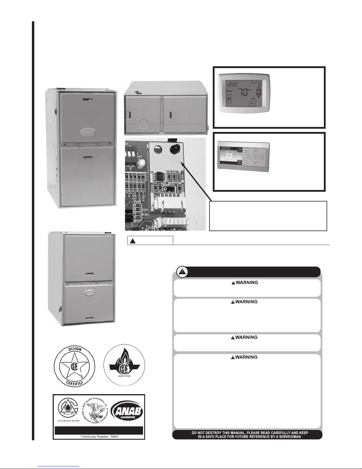
This Memory Card must be removed (broken away) from the
furnace control when the control is replaced. The card must
be inserted into the connector at J15 of the replacement control. Failure to retain this memory card with the furnace when
replacing the furnace control could result in no operation
when the furnace control is replaced.
MODULATING
THERMOSTAT
INSTALLATION
MODULATING
COMMUNICATING
THERMOSTAT
INSTALLATION
ISO 9001:2008
WARNING
!
DO NOT EXCHANGE MEMORY CARDS BETWEEN 2 OR MORE DIFFERENT FURNACES. DOING
SO COULD RESULT IN UNEXPECTED OPERATION – INCLUDING INADEQUATE AIRFLOW DURING HEATING (AND OTHER MODES) OR A LOSS OF HEAT.
RECOGNIZE THIS SYMBOL AS AN INDICATION OF IMPORTANT SAFETY
INFORMATION!
IF THE INFORMATION IN THESE INSTRUCTIONS IS NOT FOLLOWED EXACTLY, A FIRE OR EXPLOSION
MAY RESULT, CAUSING PROPERTY DAMAGE, PERSONAL INJURY OR DEATH.
THESE INSTRUCTIONS ARE INTENDED AS AN AID TO QUALIFIED SERVICE PERSONNEL FOR PROPER
INSTALLATION, ADJUSTMENT AND OPERATION OF THIS UNIT. READ THESE INSTRUCTIONS
THOROUGHLY BEFORE ATTEMPTING INSTALLATION OR OPERATION. FAILURE TO FOLLOW THESE
INSTRUCTIONS MAY RESULT IN IMPROPER INSTALLATION, ADJUSTMENT, SERVICE OR
MAINTENANCE, POSSIBLY RESULTING IN FIRE, ELECTRICAL SHOCK, CARBON MONOXIDE POISONING, EXPLOSION, PROPERTY DAMAGE, PERSONAL INJURY OR DEATH.
PROPOSITION 65 WARNING: THIS PRODUCT CONTAINS CHEMICALS KNOWN TO THE STATE OF
CALIFORNIA TO CAUSE CANCER, BIRTH DEFECTS OR OTHER REPRODUCTIVE HARM.
— Do not store or use gasoline or other flammable vapors and liquids, or other combustible materials
in the vicinity of this or any other appliance.
— WHAT TO DO IF YOU SMELL GAS
• Do not try to light any appliance.
• Do not touch any electrical switch; do not use any phone in your building.
• Immediately call your gas supplier from a neighbor’s phone. Follow the gas supplier’s instructions
• If you cannot reach your gas supplier, call the fire department.
• Do not return to your home u
— DO NOT RELY ON SMELL ALONE TO DETECT LEAKS. DUE TO VARIOUS FACTORS, YOU MAY NOT
BE ABLE TO SMELL FUEL GASES.
• U.L. recognized fuel gas and CO detectors are recommended in all applications, and their installation should be in accordance with the manufacturer’s recommendations and/or local laws, rules
regulations, or customs.
— Improper installation, adjustment, alteration, service or maintenance can cause injur
damage or death. Refer to this manual. Installation and service must be performed by a qualified
installer, service agency or the gas supplier. In the commonwealth of Massachusetts, installation
must be performed by a licensed plumber or gas fitter for appropriate fuel.
ntil authorized by the gas supplier or fire department.
y, property
92-24161-75-00
Page 2

IMPORTANT: All Rheem products
meet current Federal OSHA Guidelines
for safety. California Proposition 65
warnings are required for certain products, which are not covered by the
OSHA standards.
California's Proposition 65 requires
warnings for products sold in California
that contain, or produce, any of over
600 listed chemicals known to the
State of California to cause cancer or
birth defects such as fiberglass insulation, lead in brass, and combustion
products from natural ga
s.
All “new equipment” shipped for sale in
California will have labels stating that
the product contains and/or produces
Proposition 65 chemicals. Although we
have not changed our processes, having the same label on all our products
facilitates manufacturing and shipping.
We cannot always know “when, or if”
products will be sold in the California
market.
You may receive inquiries from customers about chemicals found in, or
produced by, some of our heating and
air-cond
itioning equipment, or found in
natural gas used with some of our
products. Listed below are those chemicals and substances commonly associated with similar equipment in our
industry and other manufacturers.
• Glass Wool (Fiberglass) Insulation
• Carbon Monoxide (CO)
• Formaldehyde
• Benzene
More details are available at the
Websites for OSHA (Occupational
Safety and Health Administration), at
www.osha.gov
and the State of
California's OEHHA (Office of
Environmental Health Hazard
Assessment), at www.oehha.org.
Consumer education is important since
the chemicals and substances on the
list are found in our daily lives. Most
consumers are aware that products
present safety and health risks, when
improperly used, handled and maintained.
Installation Instructions are updated on
a regular basis. This is done as product
changes occur or if new information
becomes available. In this publication,
an arrow ➤ denotes changes from the
previous edition or additional new
material.
TABLE OF CONTENTS
SAFETY INFORMATION ..........................................................................................................................................3
INSTALLATION CHECK LIST...................................................................................................................................5
GENERAL INFORMATION .......................................................................................................................................6
IMPORTANT INFORMATION ABOUT EFFICIENCY AND INDOOR AIR QUALITY..............................................8
LOCATION REQUIREMENTS AND CONSIDERATIONS.......................................................................................9
CLEARANCE-ACCESSIBILITY....................................................................................................................10
SITE SELECTION .........................................................................................................................................11
DIMENSIONS AND CLEARANCE TO COMBUSTIBLES...........................................................................12
UPFLOW MODELS.............................................................................................................................12
DOWNFLOW MODELS......................................................................................................................13
HORIZONTAL MODELS.....................................................................................................................14
DUCTING ......................................................................................................................................................15
SUPPLYAIR SENSOR .................................................................................................................................17
VENTING AND COMBUSTION AIR PIPING.........................................................................................................18
INSTALLATION WITH PRE-EXISTING VENT SYSTEMS..........................................................................18
JOINING PIPE AND FITTINGS....................................................................................................................19
CEMENTING JOINTS...................................................................................................................................19
NON-DIRECT VENT PIPE INSTALLATION ...........................................................................................................20
DIRECT VENT PIPE INSTALLATION ....................................................................................................................24
CONCENTRIC TERMINATIONS..................................................................................................................26
HORIZONTALTERMINATIONS...................................................................................................................28
CONDENSATE DRAIN / OPTIONAL NEUTRALIZER ..........................................................................................34
CONVERTING DOWNFLOW/HORIZONTAL MODELS TO HORIZONTAL CONFIGURATION.........................36
GAS SUPPLYAND PIPING ....................................................................................................................................39
GAS VALVE...................................................................................................................................................40
LP CONVERSION.........................................................................................................................................42
ELECTRICAL WIRING............................................................................................................................................45
ACCESSORIES.......................................................................................................................................................47
ELECTRONIC AIR CLEANER......................................................................................................................47
HUMIDIFICATIONAND DEHUMIDIFICATION............................................................................................47
OTHER ACCESSORIES ..............................................................................................................................49
TYPICAL WIRING ACCESSORIES FOR COMMUNICATING RESIDENTIAL SYSTEMS............49-50
HIGH ALTITUDE INSTALLATIONS ........................................................................................................................51
LP GAS AT HIGH ALTITUDE ELEVATIONS................................................................................................53
ZONING SYSTEMS......................................................................................................................................54
INSTALLATION WITH NON-COMMUNICATING, HIGH-EFFICIENCY PREMIUM COOLING
SYSTEMS ...................................................................................................................................................54
INTEGRATED FURNACE CONTROL ...................................................................................................................55
CONNECTORS AND COMPONENTS OF FURNACE CONTROL ...........................................................55
SPECIAL CONFIGURATION – COMM T-STAT AND NON-COMM CONDENSER ..................................56
MEMORY CARD...........................................................................................................................................60
RULES FOR WRITING, DISTRIBUTION AND ARBITRATION OF MULTIPLE COPIES OF
FURNACE SHARED DATA FOR COMMUNICATING-CAPABLE FURNACES ..............................60
REPLACING THE FURNACE CONTROL...................................................................................................63
DIPSWITCHES .............................................................................................................................................66
FURNACE OPERATION USING NON-COMMUNICATING MODULATING,
MODULATING AND TWO-STAGE T-STATS.....................................................................................69
COMMUNICATING SYSTEMS....................................................................................................................73
WIRING FOR COMMUNICATIONS...................................................................................................73
STARTUP FOR SYSTEMS CONFIGURED WITH COMMUNICATIONS........................................74
CONTINUOUS FAN OPERATION IN COMMUNICATING MODE...................................................75
ACTIVE FAULT CODES WITH COMMUNICATING SYSTEMS.......................................................75
FURNACE USER MENUS ...........................................................................................................................75
STATUS 1 ............................................................................................................................................76
STATUS 2 ............................................................................................................................................78
2 WK HIST...........................................................................................................................................78
LIFE HIST............................................................................................................................................79
FAULT HISTORY.................................................................................................................................79
UNIT INFO...........................................................................................................................................79
SETUP.................................................................................................................................................79
DIPSWITCH.........................................................................................................................................80
DUAL-FUEL OPERATION ............................................................................................................................80
START-UP PROCEDURES ....................................................................................................................................81
SEQUENCE OF OPERATION.....................................................................................................................83
SETTING INPUT RATE................................................................................................................................83
MAINTENANCE.......................................................................................................................................................84
TROUBLESHOOTING CHART ..............................................................................................................................87
NORMAL OPERATING CODES (TABLE 20) ........................................................................................................89
FURNACE FAULT CODES WITH DESCRIPTIONS AND SOLUTIONS (TABLE 21)..................................90-105
WIRE DIAGRAM – STEPPER / SERVO MODULATING VALVE (FUEL CODES HA OR HB).........................106
WIRE DIAGRAM – SOLENOID CONTROLLED MODULATING VALVE (FUEL CODES HG OR HH)............107
THERMOSTATS ....................................................................................................................................................108
NON-COMMUNICATING THERMOSTATS...............................................................................................108
THERMOSTAT WIRING (WITH WIRING DIAGRAMS) ............................................................................109
APPLICATIONS.....................................................................................................................................................112
MODULATING, TOUCH-SCREEN, NON-COMMUNICATING THERMOSTAT ((-)HC-TST412MDMS)..112
COMMUNICATING THERMOSTATS.........................................................................................................122
(-)HC-TST501CMMS PROGRAMMABLE COMMUNICATING THERMOSTAT............................124
(-)HC-TST550CMMS FULL COLOR, PROGRAMMABLE COMMUNICATING THERMOSTAT...128
2
IMPORTANT: To insure proper installation and operation of this product, completely read all instructions prior to attempting to assemble, install, operate, maintain or repair this product. Upon unpacking of the furnace, inspect all parts for
damage prior to installation and start-up.
Page 3
SAFETY INFORMATION
IMPORTANT!
THE COMMONWEALTH OF MASSACHUSETTS REQUIRES COMPLIANCE
WITH REGULATION 248 CMR 4.00
AND 5.00 FOR INSTALLATION OF
THROUGH-THE-WALL VENTED GAS
APPLIANCES AS FOLLOWS:
(a) For all side wall horizontally vented
gas fueled equipment installed in every
dwelling, building or structure used in
whole or in part for residential purposes,
including those owned or operated by
the Commonwealth and where the side
wall exhaust vent termination is less than
seven (7) feet above finished grade in
the area of the venting, including but not
limited to decks and porches, the following requirements shall be satisfied:
1. INSTALLATION OF CARBON
MONOXIDE DETECTORS. At the time of
installation of the side wall horizontal
vented gas fueled equipment, the
installing plumber or gasfitter shall
observe that a hard wired carbon
monoxide detector with an alarm and
battery back-up is installed on the floor
level where the gas equipment is to be
installed. In addition, the installing
plumber or gasfitter shall observe that a
battery operated or hard wired carbon
monoxide detector with an alarm is
installed on each additional level of the
dwelling, building or structure served by
the side wall horizontal vented gas
fueled equipment. It shall be the responsibility of the property owner to secure
the services of qualified licensed professionals for the installation of hard wired
carbon monoxide detectors.
a. In the event that the side wall horizon-
tally vented gas fueled equipment is
installed in a crawl space or an attic, the
hard wired carbon monoxide detector
with alarm and battery back-up may be
installed on the next adjacent floor level.
b. In the event that the requirements of
this subdi
time of completion of installation, the
owner shall have a period of thirty (30)
days to comply with the above requirements; provided, however, that during
said thirty (30) day period, a battery
operated carbon monoxide detector with
an alarm shall be installed.
2. APPROVED CARBON MONOXIDE
DETECTORS. Each carbon monoxide
detector as required in accordance with
the above provisions shall comply with
NFPA 720 and be ANSI/UL 2034 listed
and IAS certified.
3. SIGNAGE. A metal or plastic identification plate shall be permanently mount-
ed to the exterior of the building at a
minimum height of eight (8) feet above
grade directly in line with the exhaust
vent terminal for the horizontally vented
gas fueled heating appliance or equip-
ment. The sign shall read, in print size
no less than one-half (1/2) inch in size,
“GAS VENT DIRECTLY BELOW. KEEP
CLEAR OF ALL OBSTRUCTIONS”.
vision can not be met at the
4. INSPECTION. The state or local gas
inspector of the side wall horizontally
vented gas fueled equipment shall not
approve the installation unless, upon
inspection, the inspector observes car-
bon monoxide detectors and signage
installed in accordance with the provisions of 248 CMR 5.08(2)(a) 1 through
4.
(b) EXEMPTIONS: The following equip-
ment is exempt from 248 CMR
5.08(2)(a)1 through 4:
1. The equipment listed in Chapter 10
entitled “Equipment Not Required To Be
Vented” in the most current edition of
NFPA 54 as a
2. Product Approved side wall horizon-
tally vented gas fueled equipment
installed in a room or structure separate from the dwelling, building or structure used in whole or in part for residential purposes.
(c) MANUFACTURER REQUIREMENTS – GAS EQUIPMENT VENTING SYSTEM PROVIDED. When the
manufacturer of Product Approved side
wall horizontally vented gas equipment
provides a venting system design or
venting system components with the
equip
ment, the instructions provided by
the manufacturer for installation of the
equipment and the venting system shall
include:
1. Detailed instructions for the installation of the venting system design or the
venting system components; and
2. A complete parts list for the venting
system design or venting system.
(d) MANUFACTURER REQUIREMENTS – GAS EQUIPMENT VENTING SYSTEM NOT PROVIDED. When
the manufacturer of a Product
Approved side wall horizontally vented
gas fue
the parts for venting the flue gases, but
identifies “special venting systems”, the
following requirements shall be satisfied by the manufacturer:
1. The referenced “special venting system” instructions shall be included with
the appliance or equipment installation
instructions; and
2. The “special venting systems” shall
be Product Approved by the Board, and
the instructions for that system shall
include a parts list and detailed in
tion instructions.
(e) A copy of all installation instructions
for all Product Approved side wall hori-
zontally vented gas fueled equipment,
all venting instructions, all parts lists for
venting instructions, and/or all venting
design instructions shall remain with
the appliance or equipment at the completion of the installation.
dopted by the Board; and
led equipment does not provide
stalla-
WARNING
!
INSTALL THIS FURNACE ONLY IN
A LOCATION AND POSITION AS
SPECIFIED IN THE LOCATION
REQUIREMENTS AND CONSIDERATIONS SECTION OF THESE
INSTRUCTIONS. PROVIDE ADEQUATE COMBUSTION AND VENTILATION AIR TOTHE FURNACE
SPACE AS SPECIFIED IN THE
VENTING SECTION OF THESE
INSTRUCTIONS.
WARNING
!
PROVIDE ADEQUATE COMBUSTION AND VENTILATION AIR TO
THE FURNACE SPACE AS SPECIFIED IN THE COMBUSTION AND
VENTILATION AIR SECTION OF
THESE INSTRUCTIONS.
WARNING
!
COMBUSTION PRODUCTS MUST
BE DISCHARGED OUTDOORS.
CONNECT THIS FURNACE TO AN
APPROVEDVENT SYSTEM ONLY,
AS SPECIFIED IN VENT PIPE
INSTALLATION SECTION OF
THESE INSTRUCTIONS.
WARNING
!
NEVER TEST FOR GAS LEAKS
WITH AN OPEN FLAME. USE A
COMMERCIALLY AVAILABLE
SOAP SOLUTION MADE SPECIFICALLY FOR THE DETECTION OF
LEAKS TO CHECK ALL CONNECTIONS, AS SPECIFIED IN GAS
SUPPLY AND PIPING SECTION OF
THESE TION INSTRUCTIONS.
WARNING
!
THIS FURNACE IS NOT
APPROVED OR RECOMMENDED
FOR INSTALLATION ON ITS BACK,
WITH ACCESS DOORS FACING
UPWARDS, ORWITH SUPPLY AIR
DISCHARGING TO THE RIGHTHAND SIDE WHEN FACING THE
FRONT OF THE FURNACE. SEE
FIGURES 6 AND 7 FOR PROPER
INSTALLATION OF HORIZONTAL
MODELS.
WARNING
!
DO NOT INSTALL THIS FURNACE
IN A MOBILE HOME!! THIS FURNACE IS NOT APPROVED FOR
INSTALLATION IN A MOBILE
HOME. DOING SO COULD CAUSE
FIRE, PROPERTY DAMAGE, PERSONAL INJURY OR DEATH.
WARNING
!
USE ONLY WITH TYPE OF GAS
APPROVED FORTHIS FURNACE.
REFER TO THE FURNACE RATING
PLATE.
3
Page 4
WARNING
!
WHEN THIS FURNACE IS INSTALLED
IN A RESIDENTIAL GARAGE, IT
MUST BE INSTALLED SO THE BURNERS AND IGNITION SOURCE ARE
LOCATED NO LESS THAN 18 INCHES ABOVE THE FLOOR. THIS ISTO
REDUCE THE RISK OF IGNITING
FLAMMABLE VAPORS WHICH MAY
BE PRESENT IN A GARAGE.
ALSO,THE FURNACE MUST BE
LOCATED OR PROTECTED TO
AVOID PHYSICAL DAMAGE BY VEHICLES. FAILURETO FOLLOW THESE
WARNINGS CAN CAUSE A FIRE OR
EXPLOSION, RESULTING IN PROPERTY DAMAGE, PERSONAL INJURY
OR DEATH.
WARNING
!
USE OF THIS FURNACE IS
ALLOWED DURING CONSTRUCTION
IF THE FOLLOWING TEMPORARY
INSTALLATION REQUIREMENTS
ARE MET. INSTALLATION MUST
COMPLY WITH ALL INSTALLATION
INSTRUCTIONS INCLUDING:
• PROPER VENT INSTALLATION;
• FURNACE OPERATING UNDER
THERMOSTATIC CONTROL;
• RETURN AIR DUCT SEALED TO
THE FURNACE;
• AIR FILTERS IN PLACE;
• SET FURNACE INPUT RATE AND
TEMPERATURE RISE PER RAT-
ING PLATE MARKING;
• MEANS FOR PROVIDING OUT-
DOOR AIR REQUIRED FOR COM-
BUSTION;
• RETURN AIR TEMPERATURE
MAINTAINED BETWEEN 55°F
(13°C) AND 80°F (27°C); AND;
• CLEAN FURNACE, DUCT WORK
AND COMPONENTS UPON SUBSTANTIAL COMPLETION OF THE
CONSTRUCTION PROCESS, AND
VERIFY FURNACE OPERATING
CONDITIONS INCLUDING IGNITION, INPUT RATE,TEMPERATURE RISE AND VENTING,
ACCORDINGTO THE INSTRUCTIONS.
WARNING
!
DO NOT JUMPER OR OTHERWISE
BYPASS OVERTEMPERATURE OR
ANY OTHER LIMITS OR SWITCHES
ON THE FURNACE. IF ONE OF
THESE LIMITS OR SWITCHES
SHOULD TRIP OR OPEN, THE USER
IS TO BE INSTRUCTED TO CALL A
QUALIFIED INSTALLER, SERVICE
AGENCY OR THE GAS SUPPLIER.
FOR MANUALLY RESETABLE
SWITCHES,THE USER IS FURTHER
INSTRUCTED TO NEVER RESET THE
SWITCH, BUT TO CALL A QUALIFIED
TECHNICIAN. MANUAL RESET
SWITCHES MAY REQUIRE FURTHER
CORRECTIVE ACTIONS. FAILURE TO
FOLLOWTHIS WARNING COULD
RESULT IN CARBON MONOXIDE
POISONING, SERIOUS INJURY OR
DEATH. IF THE UNIT IS INSTALLED
IN A CLOSET,THE DOOR MUST BE
CLOSED WHEN MAKINGTHIS
CHECK. INSTALLERS AND TECHNICIANS ARE INSTRUCTED TO
REPLACE ANY LIMIT OR SAFETY
SWITCH/DEVICE ONLY WITH IDENTICAL REPLACEMENT PARTS.
WARNING
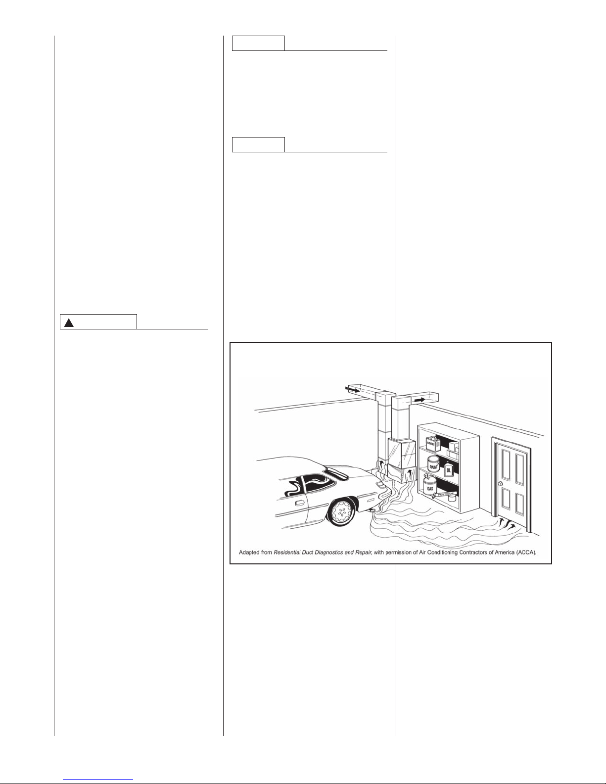
!
DUCT LEAKS CAN CREATE AN
UNBALANCED SYSTEM AND DRAW
POLLUTANTS SUCH AS DIRT, DUST,
FUMES AND ODORS INTO THE
HOME CAUSING PROPERTY DAMAGE. FUMES AND ODORS FROM
TOXIC, VOLATILE OR FLAMMABLE
CHEMICALS, AS WELL AS AUTOMOBILE EXHAUST AND CARBON
MONOXIDE (CO), CAN BE DRAWN
INTOTHE LIVING SPACETHROUGH
LEAKING DUCTS AND UNBALANCED DUCT SYSTEMS CAUSING
PERSONAL INJURY OR DEATH (SEE
FIGURE 5).
• IF AIR-MOVING EQUIPMENT OR
DUCTWORK IS LOCATED IN
GARAGES OR OFF-GARAGE
STORAGE AREAS - ALL JOINTS,
SEAMS, AND OPENINGS IN THE
EQUIPMENT AND DUCT MUST BE
SEALED TO LIMIT THE MIGRATION
OF TOXIC FUMES AND ODORS
INCLUDING CARBON MONOXIDE
FROM MIGRATING INTO THE LIVING SPACE.
• IF AIR-MOVING EQUIPMENT OR
DUCTWORK IS LOCATED IN
SPACES CONTAINING FUEL
BURNING APPLIANCES SUCH AS
WATER HEATERS OR BOILERS ALL JOINTS, SEAMS, AND OPENINGS IN THE EQUIPMENT AND
DUCT MUST ALSO BE SEALED TO
PREVENT DEPRESSURIZATION
OF THE SPACE AND POSSIBLE
MIGRATION OF COMBUSTION
BYPRODUCTS INCLUDING CARBON MONOXIDE INTOTHE LIVING
SPACE.
WARNING
!
ALWAYS INSTALL FURNACETO
OPERATE WITHIN THE FURNACE'S INTENDED TEMPERATURE-RISE RANGE WITH A DUCT
SYSTEM WHICH HAS AN EXTERNAL STATIC PRESSURE WITHIN
THE ALLOWABLE RANGE, AS
SPECIFIED IN DUCTING SECTION
OF THESE INSTRUCTIONS. SEE
ALSO FURNACE RATING PLATE.
WARNING
!
WHEN A FURNACE IS INSTALLED
SO THAT SUPPLY DUCTS CARRY
AIR CIRCULATED BYTHE FURNACETO AREAS OUTSIDE THE
SPACE CONTAINING THE FURNACE,THE RETURN AIR SHALL
ALSO BE HANDLED BY DUCT(S)
SEALED TO THE FURNACE CASING AND TERMINATING OUTSIDE
THE SPACE CONTAININGTHE
FURNACE.
NOTICE
IMPROPER INSTALLATION, OR
INSTALLATION NOT MADE IN
ACCORDANCE WITH THE CSA
INTERNATIONAL (CSA) CERTIFICATION OR THESE INSTRUCTIONS, CAN RESULT IN UNSATISFACTORY OPERATION AND/OR
DANGEROUS CONDI-TIONS AND
ARE NOT COVERED BY THE UNIT
WARRANTY.
NOTICE
IN COMPLIANCE WITH RECOGNIZED CODES, IT IS RECOMMENDED THAT AN AUXILIARY
DRAIN PAN BE INSTALLED
UNDER ALL EVAPORATOR COILS
OR UNITS CONTAINING EVAPORATOR COILS THAT ARE LOCATED IN ANY AREA OF A STRUCTURE WHERE DAMAGE TO THE
BUILDING OR BUILDING CONTENTS MAY OCCUR AS A RESULT
OF AN OVERFLOW OF THE COIL
DRAIN PAN OR A STOPPAGE IN
THE PRIMARY CONDENSATE
DRAIN PIPING. SEE ACCESSORIES SECTION OF THESE
INSTRUCTIONS FOR AUXILIARY
HORIZONTAL OVERFLOW PAN
INFORMATION (MODEL RXBM).
WARNING
!
DO NOT EXCHANGE MEMORY
CARDS BETWEEN 2 OR MORE
DIFFERENT FURNACES. DOING
SO COULD RESULT IN UNEXPECTED OPERATION – INCLUDING INADEQUATE AIRFLOW DURING HEATING (AND OTHER
MODES OR A LOSS OF HEAT).
4
Page 5

INSTALLATION CHECK LIST
REFER TO INSTALLATION INSTRUCTIONS
GAS SUPPLY
Adequate pipe size
Correct supply pressure (during furnace operation)
Manifold pressure
No gas leaks
ELECTRICAL
115 V.A.C. supply (Single Circuit)
Polarity observed
Furnace properly grounded (Earth ground)
Adequate wire size
FURNACE INSTALLATION
Adequate clearance to combustibles
Adequate clearance for service (at front)
DUCT STATIC PRESSURE
in. w.c. on heating speed
in. w.c. on cooling spe
Air temperature rise
CONDENSATE LINE
Trap filled with water
Vented
Sloped toward drain
Condensate drain line hoses connected
and clamped
ed
TERMINATIONS – DIRECT VENT
VERTICAL
Intake – 12" min. above roof/snow level
Correct relationship – exhaust to intake
VERTICAL – CONCENTRIC (RXGY-E03A)
Intake – 12" min. above roof/snow level
HORIZONTAL – STANDARD (RXGY-D02, -D02A, -D03,
-D03A)
Correct relationship – exhaust to intake
12" min. above grade/snow level
H
ORIZONTAL – ALTERNATE (RXGY-D02, -D02A, -D03,
-D03A, -D04 OR -D04A)
Correct relationship – exhaust to intake
Above anticipated snow level
HORIZONTAL – CONCENTRIC (RXGY-E03A)
12" min. above grade/snow level
Intake “Y” rotated above center
Exhaust sloped toward furnace
VENTING – NON-DIRECT VENT (VERTICAL ONLY)
in. diameter – exhaust pipe
ft. of pipe – exhaust
no. of elbows
TERMINATION – NON-DIRECT VENT (VERTICAL ONLY)
12" min. above roof/snow level
Freeze protection (if necessary)
______ Neutralizer (if needed)
VENTING – DIRECT VENT
in. diameter – intake pipe
in. diameter – exhaust pipe
ft. of pipe – intake air
no. of elbows – intake air
ft. of pipe – exhaust pipe
no. of elbows – exhaust pipe
HORIZONTAL – STANDARD
12" min. above grade/snow level
HORIZONTAL – ALTERNATE
Above anticipated snow level
Model #
Serial #
Date
of installation
5
Page 6
GENERAL INFORMATION
The RGFE, RGGE and RGJF series
furnaces are design-certified by CSA
for use with natural and L.P. gases as
follows:
• As direct vent, central forced air
furnaces with all combustion air
supplied directly to the furnace
burners through a special air intake
system outlined in these instructions.
• As non-direct, central forced air fur-
nace taking combustion air from
the installation area or using air
ducted from the outside.
• IMPORTANT: Proper application,
installation and maintenance of this
furnace are required if consumers
are to receive the full benefits for
which they have paid.
Install this furnace in accordance with
the American National Standard
Z223.1 – latest edition entitled
“National Fuel Gas Code” (NFPA54,
90A and 90B) and requirements or
codes of the local utilities or other
authorities having jurisdiction. This is
available from the following:
National Fire Protection
Association, Inc.
Batterymarch Park
Quincy, MA 02269
CSA International - U.S.
8501 East Pleasant Valley Road
Cleveland, Ohio, 44131
Canadian installations must be
installed in accordance with CSA,
local installation codes and
authorities having jurisdiction.
CSA is available from:
CSA International - Canada
178 Rexdale Blvd.
Etobicoke (Toronto), Ontario,
Canada M9W-1R3
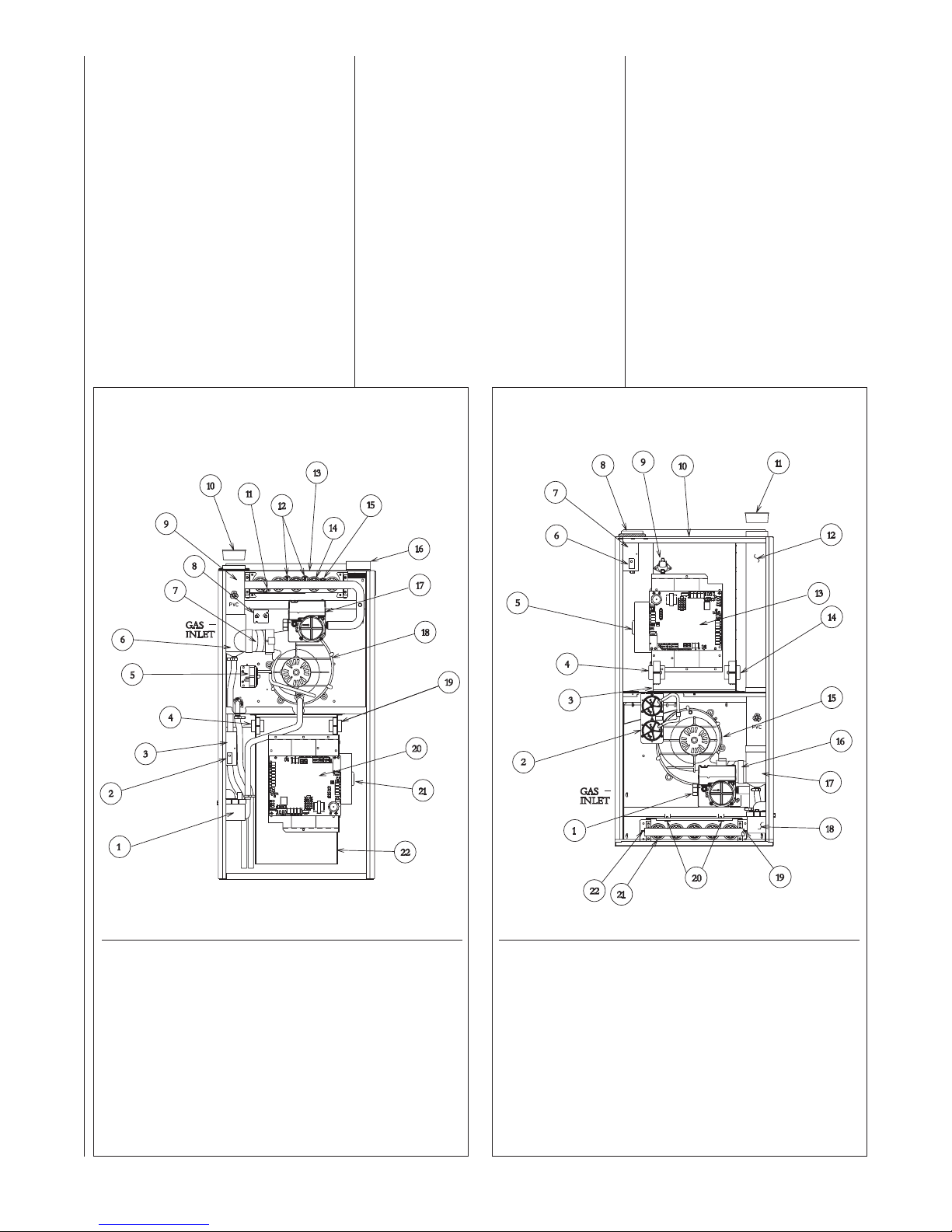
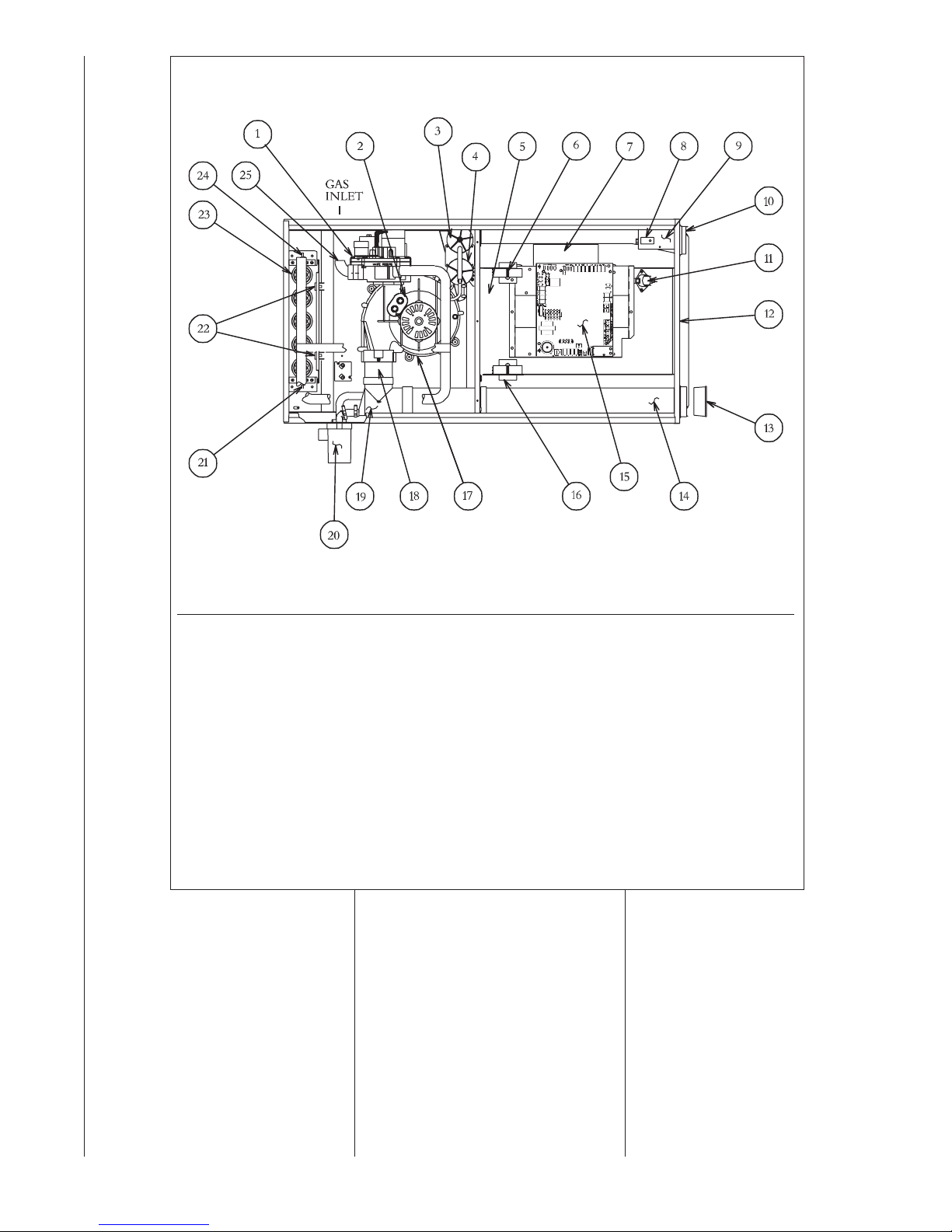
FIGURE 1
UPFLOW FURNACE RGFE
(GAS VALVE MAY BE DIFFERENT THAN SHOWN)
➤ FIGURE 2
DOWNFLOW FURNACE RGGE
(GAS VALVE MAY BE DIFFERENT THAN SHOWN)
ITEM
NO. PART NAME
1 CONDENSATE TRAP
2 DOOR SWITCH
3 JUNCTION BOX
4 TRANSFORMER
5 PRESSURE SWITCH ASSEMBLY
6 EXHAUST TRANSITION
7 CONNECTOR
8 MAIN LIMIT
9 EXHAUST AIR PIPE
10 VENT CAP SHIPPING PLUG
11 FLAME SENSOR
12 OVERTEMPERATURE SWITCH
ITEM
NO. PART NAME
13 TOP PLATE
14 BURNER
15 IGNITER
16 COMBUSTION AIR INLET
17 GAS VALVE
18 INDUCED DRAFT BLOWER
19 POWER FACTOR CHOKE
20 INTEGRATED FURNACE CONTROL
21 BLOWER MOTOR
22 BLOWER HOUSING
6
ITEM
NO. PART NAME
1 GAS VALVE
2 PRESSURE SWITCH ASSEMBLY
3 BLOWER HOUSING
4 POWER FACTOR CHOKE
5 BLOWER MOTOR
6 DOOR SWITCH
7 JUNCTION BOX
8 COMBUSTION AIR INLET
9 HALC
10 TOP PLATE
11 VENT CAP SHIPPING PLUG
ST-A1123-01_1 ST-A1123-01_2
12 OUTLET AIR PIPE
ITEM
NO. PART NAME
13 INTEGRATED FURNACE CONTROL
14 TRANSFORMER
15 INDUCED DRAFT BLOWER
16 CONNECTOR
17 EXHAUST TRANSITION
18 CONDENSATE TRAP
19 IGNITER
20 OVERTEMPERATURE SWITCH
21 BURNER
22 FLAME SENSOR
Page 7
➤ FIGURE 3
DEDICATED HORIZONTAL FURNACE RGJF
(GAS VALVE MAY BE DIFFERENT THAN SHOWN)
ITEM
NO. PART NAME
1 GAS VALVE
2 CAPACITOR (FOR INDUCER)
3 LOW PRESSURE SWITCH
4 HIGH PRESSURE SWITCH
5 BLOWER HOUSING
6 POWER FACTOR CHOKE
7 BLOWER MOTOR
8 DOOR SWITCH
9 JUNCTION BOX
10 COMBUSTION AIR INLET
11 HALC
12 TOP PLATE
13 VENT CAP PLUG
ITEM
NO. PART NAME
14 OUTLET AIR PIPE
15 INTEGRATED FURNACE CONTROL
16 TRANSFORMER
17 INDUCED DRAFT BLOWER
18 CONNECTOR
19 EXHAUST TRANSITION
20 CONDENSATE TRAP
21 IGNITER
22 OVERTEMPERATURE SWITCH
23 BURNER
24 FLAME SENSOR
25 FACTORY-INST
ALLED STREET ELBOW
ST-A107801.S01
7
Page 8
IMPORTANT INFORMATION ABOUT EFFICIENCY
AND INDOOR AIR
QUALITY
Central cooling and heating equipment is only as efficient as the duct
system that carries the cooled or
heated air. To maintain efficiency,
comfort and good indoor air quality, it
is important to have the proper balance between the air being supplied
to each room and the air returning to
the cooling and heating equipment.
Proper balance and sealing of the
duct system improves the efficiency
of the heating andair conditioning
system and improves the indoor air
quality of the home by reducing the
amount of airborne pollutants that
enter homes from spaces where the
ductwork and / or equipment is located. The manufacturer and the U.S.
Environmental Protection Agency’s
Energy Star Program recommend
that central duct systems be checked
by a qualified contractor for proper
balance and sealing.
WARNING
!
DUCT LEAKS CAN CREATE AN
UNBALANCED SYSTEM AND
DRAW POLLUTANTS SUCH AS
DIRT, DUST, FUMES AND ODORS
INTOTHE HOME CAUSING PROPERTY DAMAGE. FUMES AND
ODORS FROM TOXIC,VOLATILE
OR FLAMMABLE CHEMICALS, AS
WELL AS AUTOMOBILE EXHAUST
AND CARBON MONOXIDE (CO),
CAN BE DRAWN INTO THE LIVING
SPACE THROUGH LEAKING
DUCTS AND UNBALANCED DUCT
SYSTEMS CAUSING PERSONAL
INJURY OR DEATH (SEE FIGURE
4).
• IF AIR-MOVING EQUIPMENT OR
DUCTWORK IS LOCATED IN
GARAGES OR OFF-GARAGE
STORAGE AREAS - ALL JOINTS,
SEAMS, AND OPENINGS IN THE
EQUIPMENT AND DUCT MUST
BE SEALED TO LIMIT THE
MIGRATION OF TOXIC FUMES
AND ODORS INCLUDING CARBON MONOXIDE FROM MIGRATING INTO THE LIVING SPACE.
• IF AIR-MOVING EQUIPMENT OR
DUCTWORK IS LOCATED IN
SPACES CONTAINING FUEL
BURNING APPLIANCES SUCH
AS WATER HEATERS OR BOILERS - ALL JOINTS, SEAMS, AND
OPENINGS IN THE EQUIPMENT
AND DUCT MUST ALSO BE
SEALED TO PREVENT DEPRESSURIZATION OF THE SPACE
AND POSSIBLE MIGRATION OF
COMBUSTION BYPRODUCTS
INCLUDING CARBON MONOXIDE INTO THE LIVING SPACE.
NOTICE
IMPROPER INSTALLATION,OR
INSTALLATION NOT MADE IN
ACCORDANCE WITH THE CSA
INTERNATIONAL (CSA) CERTIFICATION OR THESE INSTRUCTIONS,
CAN RESULT IN UNSATISFACTORY
OPERATION AND/OR DANGEROUS
CONDI-TIONS AND ARE NOT COVERED BY THE UNIT WARRANTY.
NOTICE
IN COMPLIANCE WITH RECOGNIZED CODES, IT IS RECOMMEND-
ED THAT AN AUXILIARY DRAIN PAN
BE INSTALLED UNDER ALL EVAPORATOR COILS OR UNITS CONTAINING EVAPORATOR COILS THAT ARE
LOCATED IN ANY AREA OF A
STRUCTURE WHERE DAMAGE TO
THE BUILDING OR BUILDING CON-
TENTS MAY OCCUR AS A RESULT
OF AN OVERFLOW OF THE COIL
DRAIN PAN OR A STOPPAGE IN THE
PRIMARY CONDENSATE DRAIN PIP-
ING. SEE ACCESSORIES SECTION
OF THESE INSTRUCTIONS FOR
AUXILIARY HORIZONTAL OVER-
FLOW PAN INFORMATION (MODEL
RXBM).
FIGURE 4
MIGRATION OF DANGEROUS SUBSTANCES, FUMES, AND ODORS INTO LIVING SPACES
RECEIVING
Immediately upon receipt, all cartons
and contents should be inspected for
transit damage. Units with damaged
cartons should be opened immedi-
ately. If damage is found, it should
be noted on the delivery papers, and
a damage claim filed with the last
carrier.
• After unit has been delivered to
job site, remove carton taking care
not to damage unit.
• Check the unit rating plate for unit
size, electric heat, coil, voltage,
phase, etc. to be sure equipment
matches what is required for the
job specification.
• Read the entire instructions before
starting the installation.
• Some building codes require extra
cabinet insulation and gasketing
when unit is installed in attic applications.
• If
installed in an unconditioned
space, apply caulking around the
power wires, control wires, refrigerant tubing and condensate line
where they enter the cabinet. Seal
the power wires on the inside
where they exit conduit opening.
Caulking is required to prevent air
leakage into and condensate from
forming inside the unit, control box,
and on electrical controls.
• Install the unit in such a way as to
allow necessary access to the
coil/filter rack and blower/control
compartment.
• Install the unit in a level position to
ensure proper condensate
drainage. Make sure unit is level in
both directions within 1/8”.
• Install the unit in accordance with
any local code which may apply
and the national codes. Latest edi-
tions are available from: “National
Fire Protection Association, Inc.,
Batterymarch Park, Quincy, MA
02269.” These publications are:
• ANSI/NFPA No. 70-(Latest Edition)
National Electrical Code.
• NFPA90A Installation of Air
Conditioning and Ventilating
Systems.
• NFPA90B Installation of warm air
heating and air conditioning systems.
• The equipment has been evaluat-
ed in accordance with the Code of
Federal Regulations, Chapter XX,
Part 3280.
8
Page 9
LOCATION REQUIREMENTS AND CONSIDERATIONS
GENERAL INFORMATION
!
CAUTION
DO NOT USE THIS FURNACE
DURING CONSTRUCTION IF
AIR LADEN CORROSIVE COMPOUNDS ARE PRESENT SUCH
AS CHLORINE AND FLUORINE.
OTHERWISE, PROVISIONS
MUST BE TAKEN TO PROVIDE
CLEAN, UNCONTAMINATED
COMBUSTION AND VENTILATION AIR TO THE FURNACE.
FURNACE COMBUSTION AND
VENTILATION AIR CONTAMINATED WITHTHESE COMPOUNDS FORMS ACIDS DURING COMBUSTION WHICH CORRODES THE HEAT EXCHANGER
AND COMPONENT PARTS.
SOME OF THESE CONTAMINANTS ARE FOUND IN, BUT
NOT LIMITED TO, PANELING,
DRY WALL, ADHESIVES,
PAINTS, STAINS, VARNISHES,
SEALERS, AND MASONRY
CLEANING MATERIALS.
WARNING
!
DO NOT INSTALL THIS FURNACE IN A MOBILE HOME!!
THIS FURNACE IS NOT
APPROVED FOR INSTALLATION
IN A MOBILE HOME. DOING SO
COULD CAUSE FIRE, PROPERTY DAMAGE, PERSONAL
INJURY OR DEATH.
WARNING
!
WHEN THIS FURNACE IS
INSTALLED IN A RESIDENTIAL
GARAGE, IT MUST BE
INSTALLED SO THE BURNERS
AND IGNITION SOURCE ARE
LOCATED NO LESS THAN 18
INCHES ABOVE THE FLOOR.
THIS IS TO REDUCE THE RISK
OF IGNITING FLAMMABLE
VAPORS WHICH MAY
BE PRESENT IN A GARAGE.
ALSO,THE FURNACE MUST BE
LOCATED OR PROTECTED TO
AVOID PHYSICAL DAMAGE BY
VEHICLES. FAILURE TO FOLLOWTHESE WARNINGS CAN
CAUSE A FIRE OR EXPLOSION,
RESULTING IN PROPERTY DAMAGE, PERSONAL INJURY OR
DEATH.
1. IMPORTANT: If installing the unit
over a finished ceiling or living
area, be certain to install an auxil-
iary condensate drain pan under
the entire unit. Extend this auxil-
iary drain pan under any evaporator coil installed with the furnace
and the open portion of the con-
densate drain assembly. See
“Condensate Drain/Neutralizer”
section for more details.
2. IMPORTANT: If using a cooling
evaporator coil with this furnace.
Be sure the air passes over the
heat exchanger before passing
over the cooling coil. The cooled
air passing over the warm ambient
air inside the heat exchanger
tubes can cause condensation
inside the
sion and eventual failure.
3. IMPORTANT: Install the furnace
level. If it is not level, condensate
cannot drain properly, possibly
causing furnace shut down.
NOTE: These furnaces are approved
for installation in attics, as well as
alcoves, utility rooms, closets and
crawlspaces. Make provisions to pre-
vent freezing of condensate.
4. IMPORTANT: If this furnace is
installed in a garage, attic or any
other unconditioned space, a selfregulating heat tape must be
installed around the condensate
trap and along the entire length of
the condensate drain in the unconditioned space.
The heat tape should meet the following requirements:
a. The heat tape must be UL listed.
b. Install the heat tape per the
c. The heat tape should be rated
FIGURE 5
DOWNFLOW HORIZONTAL FURNACE WITH HEAT TAPE ON CONDENSATETRAP
DRAIN
PIPE
A086701
tubes resulting in corro-
manufacturer’s instructions for
the entire length of drain pipe in
the unconditioned space.
at 3 or 5 watts per foot at 120V.
SUPPLY
AIR
HEAT
TAPE
TRAP
5. IMPORTANT: If installing in a
utility room, be sure the door is
wide enough to:
a. allow the largest part of the
furnace to pass; or
b. allow any other appliance
(such as a water heater)
to pass.
6. Install the furnace level and
plumb. If it is not level, condensate cannot drain properly, possibly causing furnace to shut
down.
IMPORTANT: Do not attempt to twin
the modulating furnace. The characteristics of the ECM blower motor
preclude twinning applications.
RETURN
AIR
9
Page 10
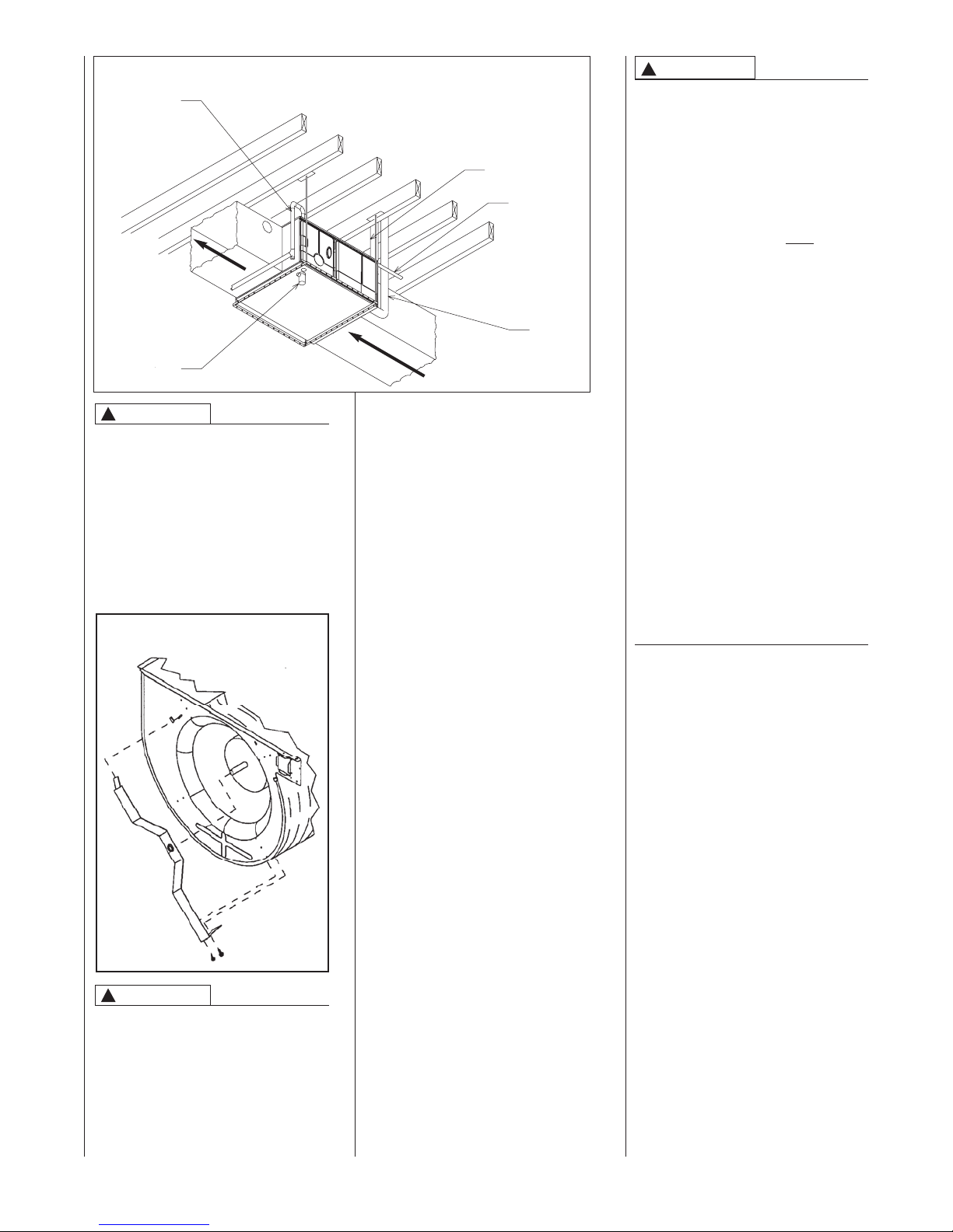
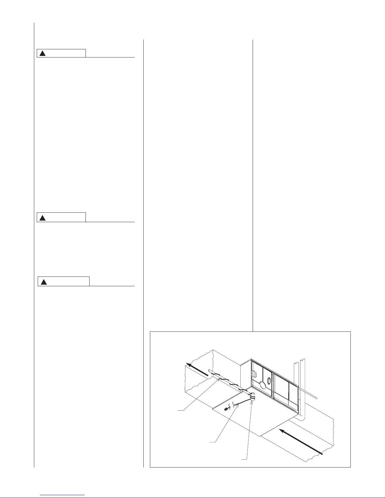
FIGURE 6
DOWNFLOW/HORIZONTAL FURNACE INSTALLED IN HORIZONTAL POSITION W/SUPPORT
BRACKETS
!
THIS FURNACE IS NOT
APPROVED OR RECOMMENDED
FOR INSTALLATION ON ITS BACK,
WITH ACCESS DOORS FACING
UPWARDS, ORWITH SUPPLY AIR
DISCHARGING TO THE RIGHT
GAS
PIPE
TRAP
CAUTION
SUPPLY
AIR
INTAKE
VENT
ELECTRICAL
CONDUIT
EXHAUST
VENT
RETURN
AIR
TH
E FOLLOWING MODELS INCLUDE
THE ADDITIONAL BRACKET (WHICH
MUST BE REMOVED) ON THE
BLOWER ASSEMBLY:
RGFE/RGGE/RGJF-09EZCMS
RGFE/RGGE/RGJF-10EZCMS
RGFE/RGGE/RGJF-12ERCMS
HAND SIDE WHEN FACING THE
FRONT OF THE FURNACE.
SEE FIGURES 6 AND 7 FOR PROPER INSTALLATION OF HORIZONTAL MODELS.
FIGURE 7
REMOVING SHIPPING BRACKET
CLEARANCE ACCESSIBILITY
The design of forced air furnaces with
models as listed in the tables under
Figures 9 and 10 are certified by CSA
Laboratories for the clearances to combustible materials shown in inches.
See name/rating plate and clearance
label for specific model number and
clearance information.
Service clearance of at least 24 inches
is recommended in front of
all furnaces.
FOR PURPOSES OF SERVICING
THIS APPLIANCE, ACCESSIBILITY
CLEARANCES, WHERE GREATER,
SHOULD TAKE PRECEDENCE OVER
FIRE PROTECTION CLEARANCES.
A086801
WARNING
!
FURNACES MUST NOT BE
INSTALLED DIRECTLY ON CARPET,
TILE OR OTHER COMBUSTIBLE
MATERIAL. INSTALLATION ON A
COMBUSTIBLE MATERIAL OTHER
THAN WOOD FLOORING MAY
RESULT IN FIRE CAUSING DAMAGE, PERSONAL INJURY OR
DEATH.
-GGE FURNACES MAY NOT
BE
INSTALLED DIRECTLYTO A COMBUSTIBLE FLOOR. A SPECIAL
FLOOR BASE IS REQUIRED.
-GFE upflow furnaces and -GGE
downflow furnaces are designed
and certified for installation on
combustible (wood only) floors.
-GGE downflow furnaces may be
installed on a cased evaporator coil
mounted on a combustible (wood
only) floor or (for installations without an evaporator coil) installed on
a special base for combustible
floors mounted to a combustible
(wood only) floor.The nece
ssary
floor base for installing a -GGE furnace in the downflow configuration
to a combustible (wood only) floor
is an accessory sold through finished goods. Following is a list of
floor base models by furnace input
size (see Figure 8).
RGGE
Furnace Special Base For
BTU’s Combustible Floors
60, 75 RXGC-B17
90, 105 RXGC-B21
120 RXGC-B24
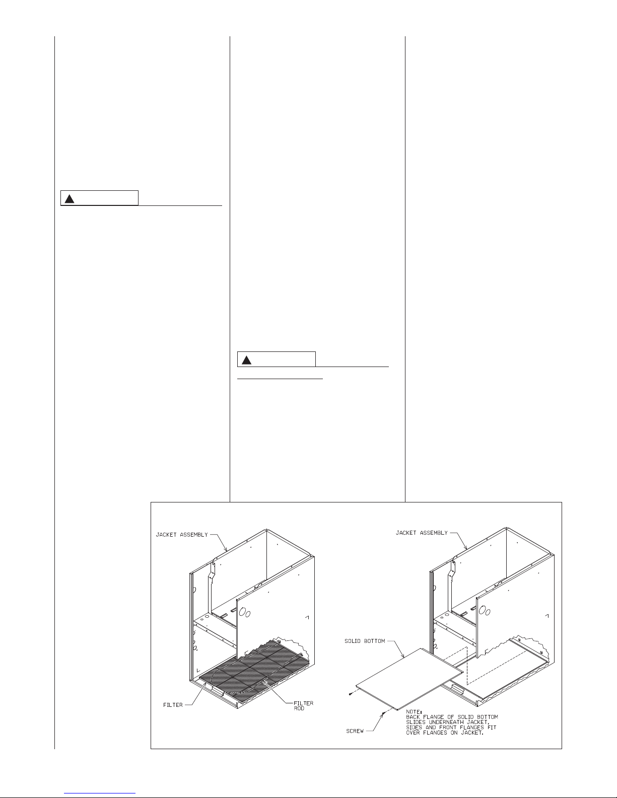
Upflow furnaces are shipped with
a bottom closure panel installed.
When bottom return air is used,
remove the panel by removing the
two screws attaching the panel to
the front base angle. See filter section for details (see Figure 12).
92-24379-01
!
CAUTION
SOME MODELS HAVE A SHIPPING
BRACKET INSTALLED TO PROTECT THE BLOWER ASSEMBLY
DURING SHIPPING.
LOCATE AND REMOVE THE SHIPPING BRACKET FROM THE SIDE
OF THE BLOWER HOUSING
BEFORE OPERATING UNIT. SEE
FIGURE 7.
10
Page 11
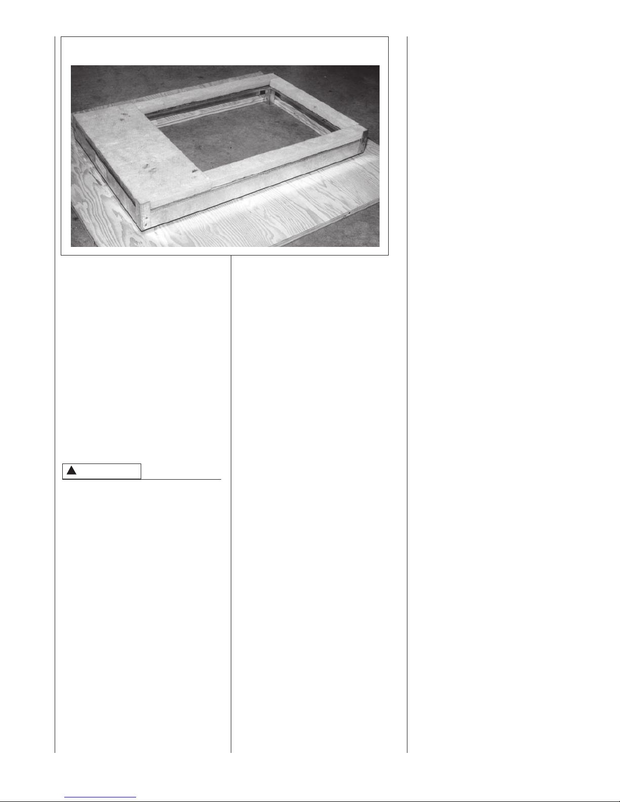
FIGURE 8
BASE FOR COMBUSTIBLE FLOORS
SITE SELECTION
1. Select a site in the building near
the center of the proposed, or exist-
ing, duct system.
2. Give consideration to the vent system piping when selecting the furnace location. Vent from the furnace to the termination with minimal length and elbows.
3. Locate the furnace near the exist-
ing gas piping. If running a new gas
line, locate the furnace to minimize
the length and elbows in the gas
piping.
4. Locate the furnace to maintain
proper clearance to combu
as shown in Figures 9, 10 & 11.
stibles
!
WARNING
COMBUSTIBLE MATERIAL MUST
NOT BE PLACED ON OR AGAINST
THE FURNACE JACKET. THE AREA
AROUND THE FURNACE MUST BE
KEPT CLEAR AND FREE OF ALL
COMBUSTIBLE MATERIALS
INCLUDING GASOLINE AND OTHER
FLAMMABLE VAPORS AND LIQUIDS. PLACEMENT OF COMBUSTIBLE MATERIALS ON,
AGAINST OR AROUND THE FURNACE JACKET CAN CAUSE AN
EXPLOSION OR FIRE RESULTING IN
PROPERTY DAMAGE, PERSONAL
INJURY OR DEATH. THE HOMEOWNER SHOULD BE CAUTIONED THAT
THE FURNACE A
USED AS A BROOM CLOSET OR
FOR ANY OTHER STORAGE PURPOSES.
REA MUST NOT BE
11
Page 12
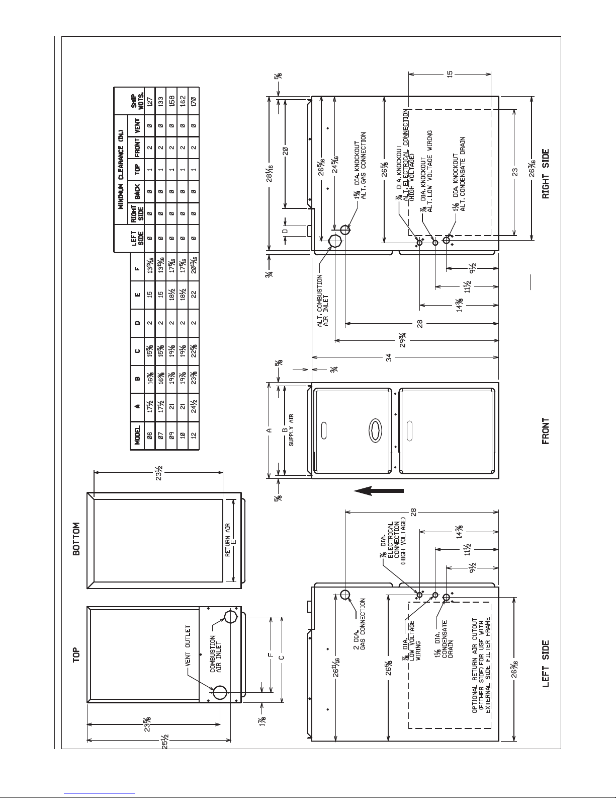
FIGURE 9
PHYSICAL DIMENSIONS AND CLEARANCE TO COMBUSTIBLES, UPFLOW MODELS
A039201
RGFE
UPFLOW MODELS
AIRFLOW
NOTE: For 1800 or more CFM, both side
returns must be used when not using a
bottom return configuration.
12
AO39201
Page 13
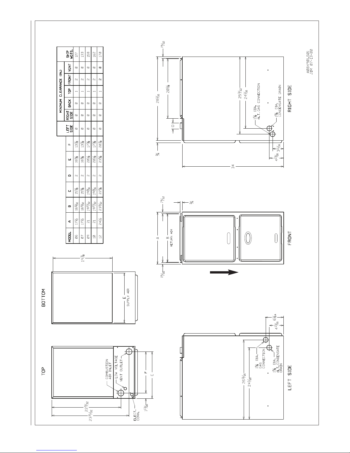
FIGURE 10
DIMENSIONS AND CLEARANCES TO COMBUSTIBLES, DOWNFLOW MODELS
RGGE
(Downflow Configuration)
FOR MODELS INSTALLED AS DOWNFLOW ONLY
AIRFLOW
13
Page 14
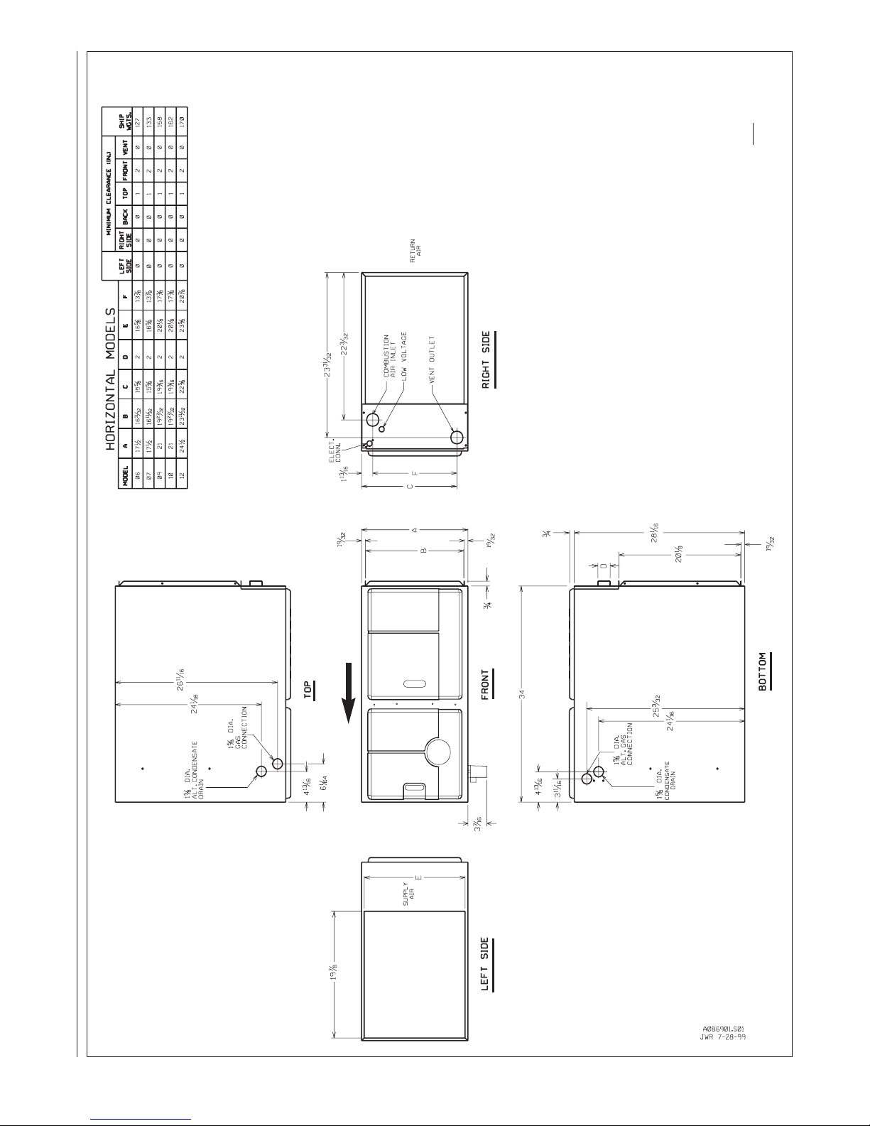
FIGURE 11
DIMENSIONS AND CLEARANCES TO COMBUSTIBLES, HORIZONTAL MODELS
NOTE: For 1800 or more CFM, both side
returns must be used when not using a
FACING THE FRONT OF THE FUR-
ONLY BE INSTALLED SO AS WHEN
IMPORTANT:THIS FURNACE MAY
NACE, SUPPLY AIR IS DIS-
CHARGED ON THE LEFT HAND
SIDE.
(RETURN)(SUPPLY)
bottom return configuration.
INSTALLED AS
configuration.)
(FUEL CODE HB ONLY)
HORIZONTAL ONLY
RGJF (ALL) & RGGE
14
on RGGE models – only
(Be sure to check the fuel code
furnaces with HB fuel codes
can be installed in horizontal
AIRFLOW
Page 15
DUCTING
Proper airflow is required for the correct
operation of this furnace.
Too little airflow can cause erratic operation and can damage the heat
exchanger. The supply and return duct
must carry the correct amount of air for
heating and cooling if summer air conditioning is used.
Size the ducts according to acceptable
industry standards and methods. The
total static pressure drop of the supply
and return duct should not exceed 0.2"
w.c.
WARNING
!
NEVER ALLOWTHE PRODUCTS
OF COMBUSTION FROMTHE
FLUE TO ENTER THE RETURN
AIR DUCTWORK ORTHE CIRCULATED AIR SUPPLY. ALL RETURN
DUCTWORK MUST BE ADEQUATELY SEALED AND
SECURED TO THE FURNACE
WITH SHEET METAL SCREWS;
AND JOINTS,TAPED. SECURE
ALL OTHER DUCT JOINTS WITH
APPROVED CONNECTIONS AND
SEAL AIRTIGHT.WHEN A FURNACE IS MOUNTED ON A PLATFORM WITH RETURN THROUGH
THE BOTTOM, IT MUST BE
SEALED AIRTIGHT BETWEEN
THE FURNACE ANDTHE RETURN
AIR PLENUM.THE FLOOR OR
PLATFORM MUST PROVIDE
PHYSICAL SUPPORT OFTHE
FURNACEWITHOUT SAGGING,
CRACKS, OR GAPS AROUND THE
BASE, PROVIDING A SEAL
BETWEEN THE SUPPORT AND
THE BASE.
FAILURE TO PREVENT PRODUCTS OF COMBUSTION FROM
BEING CIRCULATED INTOTHE
LIVING SPACE CAN CREATE
POTENTIALLY HAZARDOUS CONDITIONS, INCLUDING CARBON
MONOXIDE POISONINGTHAT
COULD RESULT IN PERSONAL
INJURY OR DEATH.
DO NOT, UNDER ANY CIRCUMSTANCES, CONNECT RETURN OR
SUPPLY DUCTWORK TO OR
FROM ANY OTHER HEAT PRODUCING DEVICE SUCH AS A
FIREPLACE INSERT, STOVE, ETC.
DOING SO MAY RESULT IN FIRE,
CARBON MONOXIDE POISONING,
EXPLOSION, PERSONAL INJURY
OR PROPERTY DAMAGE.
IMPORTANT: Some high efficiency filters
have a greater than normal resistance to
airflow. This can adversely affect furnace
operation. Be sure to check airflow if
using any filter other than the factory-provided filter.
UPFLOW UNITS
1. Position the unit to minimize long
runs of duct or runs of duct with
many turns and elbows.
WARNING
!
UPFLOW FURNACE:
BASE PLATE MUST BE INSTALLED IN
THE FURNACE BOTTOM WHEN USING
SIDE AIR RETURN. FAILURE TO
INSTALL A BASE PLATE COULD
CAUSETHE PRODUCTS OF COMBUSTION TO CIRCULATE INTOTHE LIVING
SPACE AND CREATE POTENTIALLY
HAZARDOUS CONDITIONS, INCLUDING CARBON MONOXIDE POISONING
OR DEATH.
A SOLID METAL
2. Open the return air compartment.
a. If using side return air, do not
remove the bottom base.
b. Cut an opening in the side .
The opening should be cut the
full width of the knockouts on
the
unit.
NOTE: When using side
return, return air plenums,
RXGR-C17B, C21B and C24B
are available from the factory.
c. Remove the bottom base, if
using bottom return air.
Remove the panel by removing the two screws attaching
the base to the front base
angle. See Figure 12.
NOTE: Where the maximum
airflow is 1800 CFM or more,
both sides or the bottom must
be used for return air.
3. Connect the return duct or return
air cabinet to the unit. Make the
connection air tight to prevent
entra
ining combustion gases from
an adjacent fuel-burning appli-
ance.
4. Be sure to have adequate
space for the unit filter.
NOTE: DO NOT take return air
from bathrooms, kitchens, furnace
rooms, garages, utility or laundry
rooms, or cold areas. DO NOT
use a rear air return.
5. If summer air conditioning is
desired, position the indoor coil on
the supply air side of the unit.
Insure that no air can bypass this
coil.
6. Connect the supply air plenum to
the furnace plenum opening.
IMPOR
TANT: If a flexible duct
connector must be used, it MUST
be rated for a minimum temperature of 250°F. continuous.
FIGURE 12
BOTTOM PANEL REMOVAL
NOTE: FILTERAND FILTER-ROD ARE SHIPPED
ON TOP OF SOLID BOTTOM. REMOVE FILTER
AND FILTER ROD TO ACCES SOLID BOTTOM
ADS-5422-01
15
Page 16
DOWNFLOW UNITS
1. Position the unit to minimize long
runs of duct or runs of duct with
many turns and elbows.
2. If summer air conditioning is desired,
position the indoor coil on the supply
air side of the unit. Insure that no air
can bypass this coil.
3. If installing on a combustible floor
and not using an air conditioning
plenum, install the special base for
combustible floors. See Figure 8.
!
WARNING
THE DOWNFLOW FURNACE DESIGN
IS CERTIFIED FOR INSTALLATION
ON A NON-COMBUSTIBLE FLOOR
USE THE SPECIAL BASE SPECIFIED
ON THE FURNACE CLEARANCE
LABEL. FAILURE TO INSTALLTHE
SPECIAL BASE MAY RESULT IN
FIRE, PROPERTY DAMAGE, PERSONAL INJURY OR DEATH.THIS
SPECIAL BASE IS SHIPPED FROM
THE FACTORY AS AN ACCESSORY.
4. Connect the furnace to the supply
air plenum.
5. Connect the return air ducting to
the return air opening at the top of
the unit. Make the connection air
tight to prevent entraining combus-
tion gases from an adjacent fuel-
burning appliance.
6. Be sur
eto have adequate space
for the unit filter.
NOTE: DO NOT take return air
from bathrooms, kitchens, furnace
rooms, garages, utility or laundry
rooms, or cold areas.
.
Return air can come from : (1) outside the building, (2) from return air
ducting from several inside rooms, or (3)
a combination of the two. When using
outside air, design and adjust the sys-
tem to maintain a return air temperature
above 55°F during the heating season.
If return air comes from both inside and
outside the building, design the ducting
system with a diverting damper so that
the volume of return air entering the furnace equals that which would normally
enter thr
furnace. Any duct opening pulling return
air from the outside must not be any
higher nor closer than 10 feet to the fur-
nace exhaust vent.
ough the return air intake of the
16
Page 17
SUPPLY AIR SENSOR
Each furnace comes shipped from the
factory with a supply air sensor. Install
the sensor, in the supply air plenum
trunk, with two, field supplied, #8 sheet
metal screws, using the following guidelines:
1. 12” downstream of the evaporator
coil, if installed.
2. If no evaporator coil is used, locate
the sensor out of direct line-of-site
of the heat exchanger and not closer than 18” downstream of the furnace outlet.
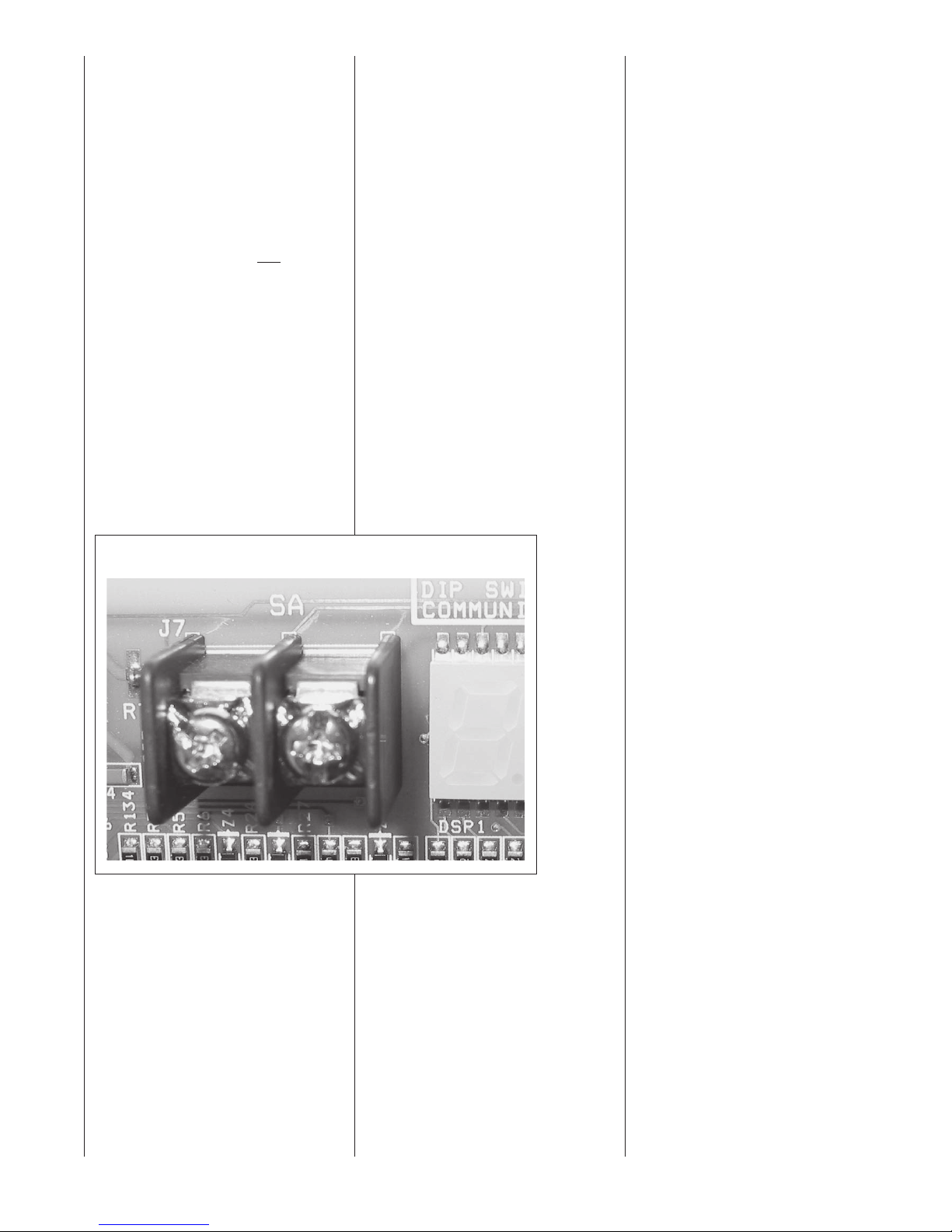
3. Attach the supply air sensor wires
onto the terminals marked “SA
Sensor” on the integrated furnace
control board (See Figure 13).
4. Do not extend the supply-air sensor
wire.
NOTE: Improper placement of the
supply air sensor can adversely
affect furnace temperature rise.
NOTE: In downflow circumstances
where building construction does not
allow for the placement of the sensor to
fall within these parameters, the supply
air sensor should not be connected.
This means that the furnace will run
under default parameters. When running under default parameters, the “82”
code will appear for 90 seconds. After
that, the fault code will be stored in the
control board’s memory and will show
only upon power cycling. Default airflow
parameters can be manually adjusted.
See section discussing Integrated
Furnace Control (IFC) board in this
manual.
For communicating systems, the
supply air se
off so that a fault code will not be
displayed at all. This can be done in
the furnace setup menu of a communicating thermostat. See the section
of this manual titled Communicating
Systems under sub-section titled
Furnace User Menus (Setup).
nsor input can be turned
FIGURE 13
SUPPLY AIR SENSOR TERMINALS
17
Page 18
VENTING AND COMBUSTION AIR PIPING
GENERAL INFORMATION
WARNING
!
READ AND FOLLOW ALL
INSTRUCTIONS IN THIS SECTION. FAILURETO PROPERLY
VENT THIS FURNACE OR PROTECT IT FROM INADEQUATE
COMBUSTION AIR CAN CAUSE
CARBON MONOXIDE POISONING, AN EXPLOSION OR FIRE,
RESULTING IN PROPERTY DAMAGE, PERSONAL INJURY OR
DEATH.
OVERTEMPERATURE
SAFETY SWITCHES
Furnaces are equipped with safety
switches in the burner compartment to
protect against over temperature conditions. If a switch is tripped, it must be
manually reset.
WARNING
!
DO NOT JUMPER OVERTEMPERATURE OR ANY OTHER
SAFETY SWITCHES! IF ONE OF
THESE OVER TEMPERATURE
SWITCHES SHOULD TRIP, CALL
A QUALIFIED INSTALLER, SERVICE AGENCY OR THE GAS
SUPPLIER. DO NOT RESET THE
SWITCHES WITHOUTTAKING
CORRECTIVE ACTION. FAILURE
TO DO SO CAN RESULT IN CARBON MONOXIDE POISONING OR
DEATH. IF THIS UNIT IS
INSTALLED IN A CLOSET, THE
DOOR MUST BE CLOSEDWHEN
MAKING THIS CHECK.
REPLACETHE OVER TEMPERATURE SAFETY SWITCHES ONLY
WITH THE IDENTICAL REPLACEMENT PART.
WARNING
!
IN CANADA, PRODUCTS CERTIFIED FOR INSTALLATION AND
INTENDED TO BE VENTEDWITH
PLASTIC VENT SYSTEMS (PVC,
CPVC) MUST USE VENT SYSTEMS THAT ARE CERTIFIED TO
THE STANDARD FOR TYPE BH
GAS VENTING SYSTEMS, ULC
S636.
THE COMPONENTS OF THE
CERTIFIED MATERIAL MUST
NOT BE INTERCHANGED WITH
OTHER VENT SYSTEMS OR
UNLISTED PIPE/FITTINGS.
PLASTIC COMPONENTS AND
SPECIFIED PRIMERS AND
GLUES OF THE CERTIFIED SYSTEM MUST BE FROM A SINGLE
SYSTEM MANUFACTURER AND
NOT INTERMIXED WITH OTHER
SYSTEM MANUFACTURER’S
PARTS.
NOTE: INLET AIR PIPING IS NOT
CONSIDERED TO BE A PART OF
THE “VENTING SYSTEM”.THE
REQUIREMENT THATVENT MATERIAL BE CERTIFIED TO ULC S636
DOES NOT APPLY TO INLET AIR
PIPING.
INSTALLATION WITH
PRE-EXISTING VENT
SYSTEMS
When the installation of this furnace
replaces an existing furnace that is
removed from a vent system serving
other appliances (such as a water
heater), the existing vent system is likely
to be too large to proper
remaining attached appliances.
Follow the steps below with each appliance remaining connected to the original common vent system. Place the
appliance to be tested in operation,
while the other appliances remaining
connected to the common vent system
are not in operation. Test the operation
of each appliance individually by the following method.
1. Permanently seal any unused
openings in the common venting
system.
2. Visually inspect the venting system
f
or proper size and horizontal pitch
and determine that there is no
blockage, restriction, leakage, corrosion or other deficiencies which
could cause an unsafe condition.
3. If practical, close all building doors,
windows and all doors between the
space where the appliances
remaining connected to the common venting system are located.
Turn on clothes dryers and any
appliance not connected to the
ly vent the
common venting system. Turn
on any exhaust fans, such as
range hoods and ba
exhausts, so they will operate at
maximum speed. Do not operate
a summer exhaust fan. Close
fireplace dampers.
4. Follow the lighting instructions.
Place the appliance being
inspected into operation. Adjust
the thermostat so the appliance
will operate continuously.
5. Test for spillage at the draft hood
relief opening after 5 minutes of
main burner operation. Use the
flame of a match or candle, or
smoke from a cigarette, cigar
or pipe.
6. After it has been determined
each appliance that remains connected to the common venting
system properly vents (when
tested as outlined above), return
doors, windows, exhaust fans,
fireplace dampers and any other
gas-burning appliance to their
previous conditions of use.
7. If improper venting is observed
during any of the above tests,
resize the common venting sys-
tem. Refer to latest edition of the
National Fuel Gas Code ANSI
Z223.1, or the CSA-GAMA venting tables for Category I furnaces
.
NOTE: For U.S. installations
only. Schedule 40 ABS-DWV
pipe and fittings may be used as
an alternate to PVC pipe for the
combustion air inlet and vent
pipes.
NOTE: For U.S. installations
only. Cellular core PVC is also
approved for use. It must be
schedule 40 PVC-DWV cellular
pipe manufactured under ASTM
F-891.
throom
that
18
Page 19

JOINING PIPE AND
FITTINGS
WARNING
!
PVC SOLVENT CEMENTS AND
PRIMERS ARE HIGHLY FLAMMABLE. PROVIDE ADEQUATE
VENTILATION AND DO NOT
ASSEMBLE COMPONENTS
NEAR HEAT SOURCE OR AN
OPEN FLAME. DO NOT
SMOKE. AVOID SKIN OR EYE
CONTACT. OBSERVE ALL CAUTIONS AND WARNINGS PRINTED ON MATERIAL CONTAINERS. FAILURETO FOLLOW
THESE GUIDELINES MAY
RESULT IN FIRE, EXPLOSION
OR ASPHYXIATION CAUSING
PERSONAL INJURY OR DEATH.
All pipe, fittings, solvent cement,
primers and procedures must conform
to American National Standard
Institute and American Society for
Testing and Materials (ANSI/ASTM)
standards as shown below:
IMPORTANT: The plastic combustion
air and venting components are MADE
of PVC. If using ABS piping, ensure that
the solvent cement is compatible for
joining PVC to ABS components or use
a mechanical connection that can withstand the vent temperatures and is corrosion resistant.
CEMENTING JOINTS
Properly seal all joints in the PVC vent
using the following materials and procedures:
PVC CLEANER-PRIMER AND
PVC MEDIUM-BODY SOLVENT
CEMENT
IMPORTANT: After cutting pipe, remove
all ragged edges and burrs. This is
important to prevent increase in pressure drop throughout the system.
1. Cut pipe end square. Chamfer edge
of pipe. Clean fitting socket and
pipe joint area of all dirt, grease and
moisture.
2. After checking pipe and socket for
proper fit, wipe socket
cleaner-primer. Apply
a liberal coat of primer to inside surface of socket and outside of pipe.
READ INSTRUCTIONS INCLUDED
WITH THE PRIMER FOR PROPER
INSTALLATION.
and pipe with
3. Apply a thin coat of cement
evenly in the socket. Quickly
apply a heavy coat of cement to
the pipe end and insert pipe into
fitting with a slight twisting movement until it bottoms out.
NOTE: Cement must be fluid; if
not, recoat.
4. Hold the pipe in the fitting for 30
seconds to prevent the tapered
socket from pushing the pipe out
of the fitting.
5. Wipe all excess cement from the
joint with a rag. Allow 15 minutes
before handling. Cure time varies
according to fit, temperature and
humidity.
NOTE: Stir the solvent cement
frequently while using. Use a
natural bristle, one inch wide
brush or the applicator supplied
with the can.
IMPORTANT: For Proper Installation
DO NOT use solvent cement that has
become curdled, lumpy or thickened.
DO NOT thin. Observe shelf precautions printed on containers. For application below 32°F, use only low-temperature-type solvent cement.
For correct installation of the vent
pipe, follow the instructions provided
by the manufacturers of the pipe,
primer and solvent.
PIPE & FITTING MATERIAL
Schedule 40 PVC (Pipe) D1785
Schedule 40 PVC (Cellular Core Pipe) F891
Schedule 40 PVC (Fittings) D2466
SDR-21PVC (Pipe) D2241
SDR-26 PVC (Pipe) D2241
Schedule 40 ABS Cellular Core DWV (Pipe) F628
Schedule 40 ABS (Pipe) D1527
Schedule 40 ABS (Fittings) D2468
ABS-DWV (Drain Waste & Vent)
(Pipe & Fittings)
PVC-DWV (Drain Waste & Vent)
(Pipe & Fittings)
ASTM
SPECIFICATION
D2661
D2665
19
Page 20
NON-DIRECT VENT PIPE INSTALLATION
(FOR VERTICALTERMINATIONS ONLY)
COMBUSTION AIR
WARNING
!
ALWAYS PROVIDE THIS FURNACE AND ANY OTHER FUEL
BURNING APPLIANCE WITH
ENOUGH FRESH AIR FOR
PROPER COMBUSTION AND
VENTILATION OF THE FLUE
GASES. MOST BUILDING
CODES REQUIRE THAT OUTSIDE AIR BE SUPPLIED INTO
THE FURNACE AREA. FAILURE TO DO SO CAN CAUSE
DEATH FROM CARBON
MONOXIDE POISONING.
Provide adequate facilities for combustion and ventilation air in accordance with section 5.3, Air for
Combustion and Ventilation of the
National Fuel Gas Code, ANS
Z223.1 - latest edition; CAN/CGA
B149.1 and .2, or applicable provisions of the local building codes.
These combustion and ventilation
facilities must not be obstructed.
IMPORTANT: Air for combustion and
ventilation must not come from a
corrosive atmosphere. Any furnace
failure due to corrosive elements in
the atmosphere is excluded from
warranty coverage.
I
The following types of installation (but
not limited to the following) REQUIRE
OUTDOOR AIR for combustion, d
to chemical exposures:
• Commercial buildings
• Buildings with indoor pools
• Furnaces installed in laundry
rooms
• Furnaces in hobby or craft rooms
• Furnaces installed near chemical
storage areas.
Exposure to the following substances
in the combustion air supply (but not
limited to the following) also
REQUIRE OUTDOOR AIR for combustion:
• Permanent wave solutions
• Chlorinated waxes and cleaners
• Chlorine-based swimming pool
chemicals
• Water softening chemica
• De-icing salts or chemicals
• Carbon Tetrachloride
• Halogen type refrigerants
• Cleaning solvents (such as per-
chloroethylene)
• Printing inks, paint removers,
varnishes, etc.
• Hydrochloric acid
• Cements and glues
• Anti-static fabric softeners for
clothes dryers
• Masonry acid washing materials
Combustion air must be free of acid
forming chemicals such as sulphur,
fluorine, and chlorine. These elements are found in aerosol sprays,
detergents, bleaches, cl
vents, air fresheners, paint and varnish removers, refrigerants and many
other commercial and household
products. Vapors from these products
when burned in a gas flame form acid
compounds. The acid compounds
increase the dew point temperature
of the flue products and produce
highly corrosive condensate.
eaning sol-
ue
ls
WARNING
!
ALL FURNACE INSTALLATIONS
MUST COMPLY WITHTHE
NATIONAL FUEL GAS CODE AND
LOCAL CODES TO PROVIDE ADEQUATE COMBUSTION AND VENTILATION AIR FOR THE FURNACE.
FAILURE TO DO SO CAN RESULT
IN EXPLOSION, FIRE, PROPERTY
DAMAGE, CARBON MONOXIDE
POISONING, PERSONAL INJURY
OR DEATH.
Combustion air requirements are
determined by whether the furnace
is in an open (unconfined) area or in
a confined space such as a closet or
small room.
FURNACE LOCA
UNCONFINED SPACE
Using indoor air for combustion.
An unconfined space must have at
least 50 cubic feet for each 1,000
BTUH of the total input for all
appliances in the space. Here are a
few examples of the room sizes
required for different inputs. The
sizes are based on 8 foot ceilings.
See Table 1.
TABLE 1
UNCONFINED SPACE DIMENSIONS
BTUH Minimum Sq. Feet Typical Room Size
Input With 8 foot Ceiling
60,000 375 15' x 25' OR 19' x 20'
75,000 469 15' x 32' OR 20' x 24'
90,000 563 20' x 28' OR 24' x 24'
105,000 657 20' x 33' OR 26' x 25'
120,000 750 25' x 30' OR 24' x 32'
If the open space containing the furnace is in a building constructed to
severely limit outside air infiltration
(contemporary energy efficient construction methods), o
still be required for the furnace to
operate and vent properly. Outside
air openings should be sized the
same as for a confined space.
TED IN AN
utside air may
20
Page 21
FURNACE LOCATED IN A
CONFINED SPACE.
A confined space (any space smaller than shown before as “unconfined”) must have openings into
the space, which are located in
accordance with the requirements set forth in the following
subsections A and B. The open-
ings must be sized by how they
connect to the heated area or to the
outside, and by the input of all
appliances in the space.
If the confined space is within a
building with tight construction,
combustion air must be taken fro
m
outdoors or areas freely communicating with the outdoors.
TABLE 2
INDOOR AIR OPENING DIMENSIONS
BTUH Free Area
Input Each Opening
60,000 100 square inches
75,000 100 square inches
90,000 100 square inches
105,000 105 square inches
120,000 120 square inches
FIGURE 14
AIR FROM HEATED SPACE
A. USING INDOOR AIR FOR
COMBUSTION
IMPORTANT: DO NOT take air from
a heated space with a fireplace,
exhaust fan or other device that may
produce a negative pressure.
If combustion air is taken from the
heated area (see Figure 14), the
openings must each have at least
100 square inches of free area.
Each opening must have at least
one square inch of free area for
each 1,000 BTUH of total input in
the space. See Table 2.
B. USING OUTDOOR AIR FOR
COMBUSTION
IMPORTANT: Do not take air from
an attic space that is equipped with
power ventilation.
The confined space must communicate with the outdoors in accordance
with Methods 1 or 2. The minimum
dimension of air openings shall not
be less than 3 inches. Where ducts
are used, they shall be of the same
cross-sectional area as the free area
of the openings to which they connect.
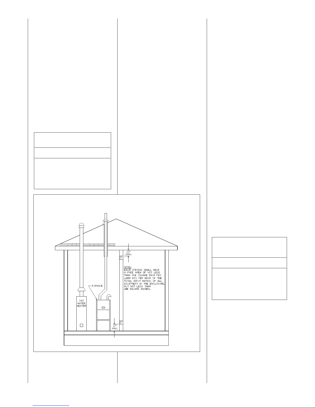
Method 1
Two permanent openings, one locat-
ed within 12 inches of the top and
one located within 12 inches of the
bottom of the enclosure, shall be pro-
vided. The openings shall communi-
cate directly, or by ducts, with the out-
doors or spaces (crawl or attic) that
freely communicate with the out-
doors.
a. Where directly communicating
with the outdoors or where communicating to the outdoors
through vertical ducts as shown in
Figure 15, each opening shall
have a minimum free area of 1
square inch for each 4000 BTUH
of total appliance input rating in
the enclosure. See Table 3.
A077501
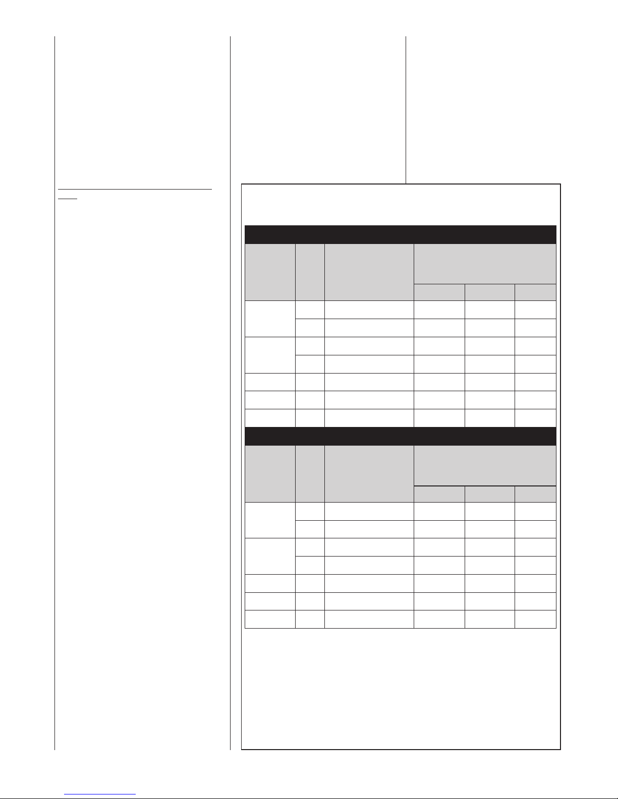
TABLE 3
VERTICAL OUTDOOR AIR OPENING
DIMENSIONS
BTUH Free Area Round Pipe
Input Each Opening Size
60,000 15.00 square inches 5"
75,000 18.75 square inches 5"
90,000 22.50 square inches 6"
105,000 26.25 square inches 6"
120,000 30.00 square inches 7"
21
Page 22
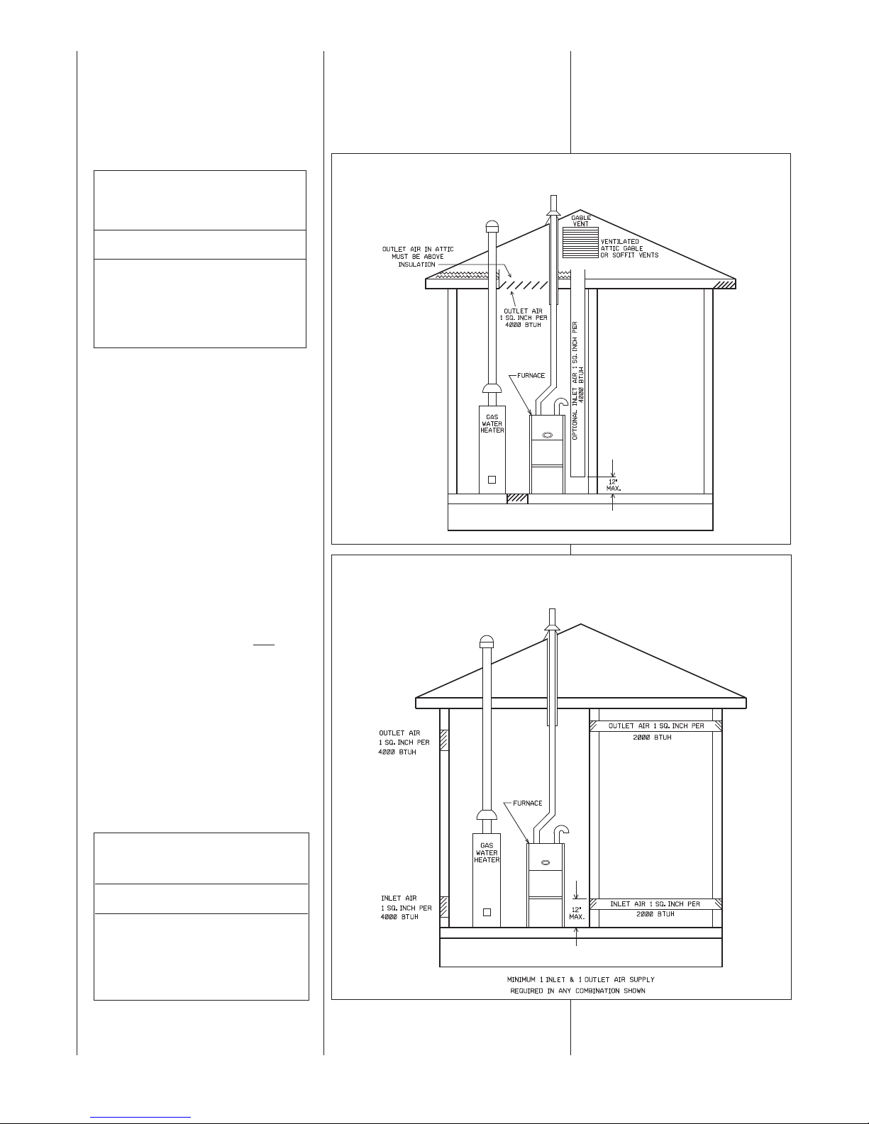
b. Where communicating with out-
doors through horizontal ducts,
each opening shall have a minimum
free area of 1 square inch for each
2000 BTUH of total input rating of
all equipment in the enclosure. See
Table 4 and Figure 16.
TABLE 4
HORIZONTAL OUTDOOR AIR
OPENING DIMENSIONS
BTUH Free Area Round Pipe
Input Each Opening Size
60,000 30.00 square inches 7"
75,000 37.50 square inches 7"
90,000 45.00 square inches 8"
105,000 52.50 square inches 9"
120,000 60.00 square inches 9"
Method 2
One permanent opening, located
within 12 inches of the top of the
enclosure, shall be permitted where
the equipment has clearances of at
least 1 inch from the sides and back
and 6 inches from the front of the
appliance. The opening shall directly
communicate with the outdoors or
communicate through a vertical or
horizontal duct to the outdoors or
spaces (crawl or attic) that freely
communicate with the outdoors, and
shall have a minimum free area of:
a. One square inch for each 3000
BTUH of the total input rating of
all equipment located in the
enclosure (see Table 5), and
Combustion air openings must not be
restricted in any manner.
CONSULT LOCAL CODES FOR SPECIAL REQUIREMENTS.
FIGURE 15
AIR FROM ATTIC/CRAWL SPACE
A077601
FIGURE 16
OUTSIDE AIR USING A HORIZONTAL INLET & OUTLET
b. Not less than the sum of the
areas of all vent connectors in the
confined space.
If the unit is installed where there is
an exhaust fan, sufficient ventilation
must be provided to prevent the
exhaust fan from creating a negative
pressure.
TABLE 5
VERTICAL OR HORIZONTAL
OUTDOOR AIR OPENING DIMENSIONS
BTUH Free Area Round Pipe
Input Each Opening Size
60,000 20.00 square inches 6"
75,000 25.00 square inches 6"
90,000 30.00 square inches 7"
105,000 35.00 square inches 7"
120,000 40.00 square inches 8"
22
A077701
Page 23
INSTALLATION GUIDELINES
IMPORTANT: When installed as a non-
direct furnace, only vertical terminations
are allowed. Do not use horizontal termi-
nations when the furnace is installed with
a non-direct vent.
All exhaust vent piping must be installed
in compliance with Part 7, Venting of
Equipment, of the latest edition of the
National Fuel Gas Code NFPA 54/ANSI
A223.1, or CAN/CGA-B149.1 and .2,
local codes or ordinances and these
instructions.
7. The minimum vent length is 5 feet.
8. All piping through the roof is 2".
When using 3" pipe, reduce to
2" within 18" of the inside of the
roof.
9. Vertical through-the-roof installations do not require any special
vent termination. Use 2" PVC
pipe extending a minimum of 12
inches above the anticipated
level of snow accumulation.
10. Elbows must be a mini
mum of
15” apart.
11. No screens may be used to
cover combustion air or
exhaust.
VENTING GUIDELINES - Non-
Direct
Vent
1. IMPORTANT: Do not common vent
with any other appliance. Do not
install in the same chase or chimney with a metal or high temperature plastic pipe from another gas or
fuel-burning appliance unless the
required minimum clearances to
combustibles are maintained
between the PVC pipe and other
pipes.
2. Use only medium or long radius
sweep elbows, such as PVC-DWV
elbows.
NOTE: For upflow and downflow
installations, extend the exhaust
pipe a minimum of 18" vertically
above t
he furnace cabinet before
turning the vent.
3. Vertical vent piping is preferred.
4. Install all horizontal piping as fol-
lows:
• Slope horizontal vent piping
upward a minimum of 1/4" per
foot of run so that condensate
drains toward the furnace.
• Support horizontal vent piping at
least every four feet. No sags or
dips are permitted.
5. Insulate all vent runs through
unconditioned spaces where below-
freezing temperatures are expected,
with 1" thick medium density, foil
ced fiber glass or equivalent
fa
Rubatex/Armaflex insulation. For
horizontal runs where water may
collect and freeze, wrap the vent
pipe with self-regulating, 3 or 5 Watt
heat tape. The heat tape must be
U.L. listed and installed per the
manufacturer’s instructions.
6. All piping between the furnace and
the roof penetration is 2" or 3" as
specified in Table 6. Table 6 lists the
maximum allowable exhaust vent
pipe length for the number of
elbows used, based on the furnace
size.
PORTANT: Use Only standard
IM
vertical terminations when installing
the modulating furnace as a nondirect vent appliance.
➤ TABLE 6
NON-DIRECT VENT APPLICATIONS
MAXIMUM ALLOWABLE LENGTH IN FEET OF EXHAUST PIPE
UPFLOW FURNACES RGFE
NUMBER OF ELBOWS
22°, 45° OR 90°
MEDIUM / LONG RADIUS ONLY
1-2 3-4 5-6
40'
120'
20'
120'
110'
110'
35'
120'
15'
120'
105'
105'
30'
120'
10'
120'
95'
95'
FURNACE
INPUT
60,000
75,000
90,000
105,000
120,000
PIPE
SIZE
(VERTICAL VENT
TERMINATIONS
ONLY)
TERMINATION
2"
3"
2"
3"
3"
3"
STANDARD
STANDARD
STANDARD
STANDARD
STANDARD
STANDARD
3" 45' 35' 30'STANDARD
DOWNFLOW AND HORIZONTAL FURNACES RGGE AND RGJF
FURNACE
INPUT
PIPE
SIZE
(VERTICAL VENT
TERMINATIONS
ONLY)
TERMINATION
2"
STANDARD
60,000
3"
2"
STANDARD
STANDARD
75,000
3"
90,000
105,000
120,000
NOTES:
1. N.R. - NOT RECOMMENDED.
2. MAXIMUM OF 6 ELBOWS MAY BE USED. DO NOT COUNT ELBOWS IN ALTERNATE TERMINATION KIT.
MEDIUM OR LONG SWEEP ELBOWS MAY BE USED.
3. A 45 OR 22.5 DEGREE ELBOW IS CONSIDERED ONE ELBOW.
4. CONCENTRIC TERMINATION NO. RXGY-E03A IS FOR THRU-THE-ROOF OR THRU-THE-WALL VENTING.
5. USE KITS RXGY-D02 OR D02A (2") OR RXGY-D03 OR D03A (3") FOR STANDARD OR ALTERNATE
THRU-THE-WALL VENTING.
6. USE KITS RXGY-D04 OR D04A FOR ALTERNATE VENTING OF 120,000 BTUH UNITS
7. NO SCREENS MAY BE USED TO COVER COMBUSTION AIR AND EXHAUST.
* A = 17
B = 21” CABINET WIDTH
3"
3"
3" 40' 35' 30'STANDARD
1
⁄2” CABINET WIDTH
STANDARD
STANDARD
STANDARD
NUMBER OF ELBOWS
22°, 45° OR 90°
MEDIUM / LONG RADIUS ONLY
1-2 3-4 5-6
30'
120'
20'
120'
90'
45'
25'
120'
15'
120'
80'
40'
WITH LONG RUNS.
20'
120'
10'
120'
75'
35'
23
Page 24
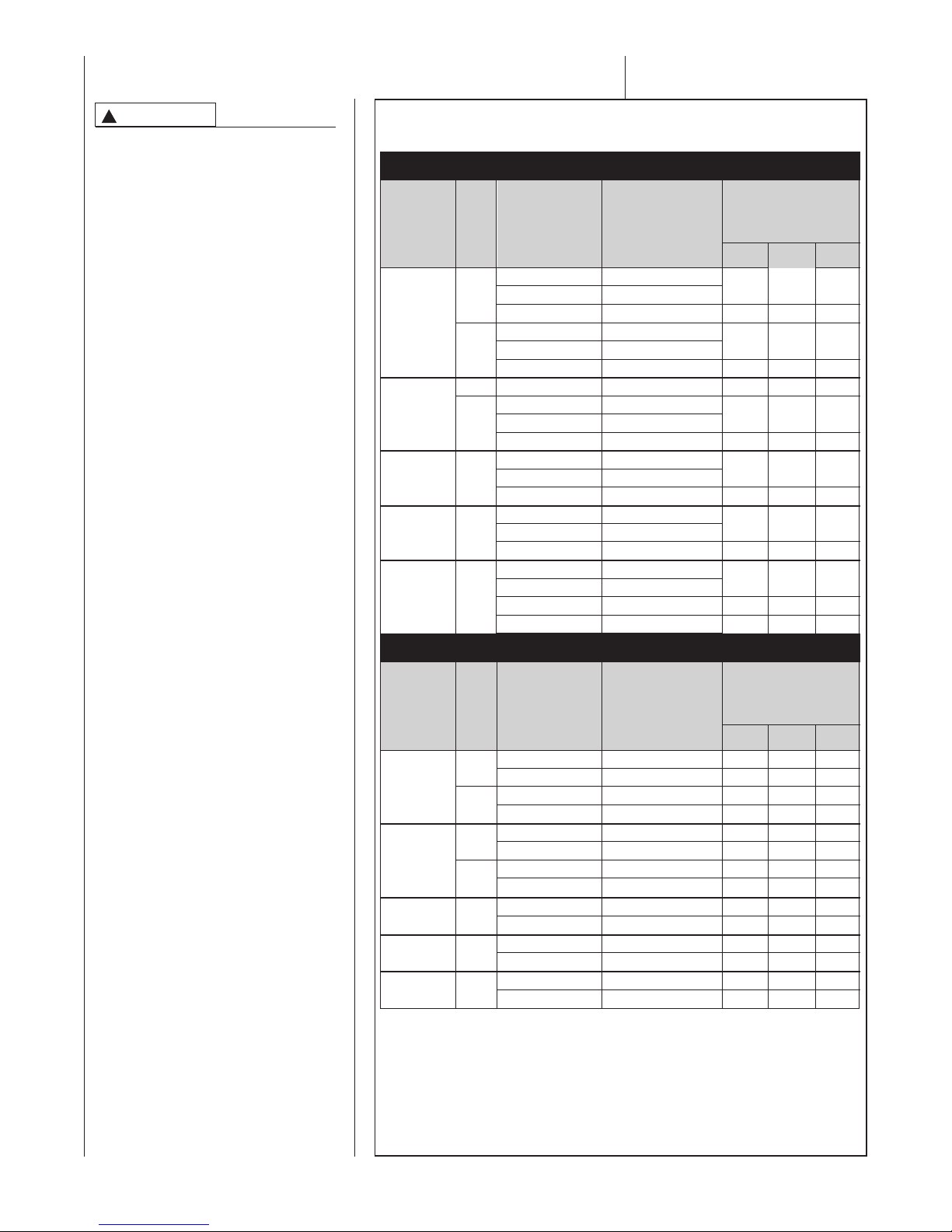
DIRECT VENT PIPE INSTALLATION
WARNING
!
READ AND FOLLOW ALL
INSTRUCTIONS IN THIS SECTION. FAILURETO PROPERLY
VENT THIS FURNACE CAN
CAUSE CARBON MONOXIDE
POISONING OR AN EXPLOSION
OR FIRE, RESULTING IN PROPERTY DAMAGE, PERSONAL
INJURY OR DEATH.
Direct vent installations require a dedicated combustion air and venting system. All air for combustion is taken
from outside and all combustion products are discharged to the outdoors.
Therefore, no ventilation or combustion air openings are required.
INSTALLATION
GUIDELINES
All exhaust piping must be installed in
compliance with Part 7, “Venting of
Equipment,” of the latest edition of the
National Fuel Gas Code NPFA 54, 90A
and 90B ANSI Z223.1-, local codes or
ordinances and these instructions.
1. IMPORTANT: Do not common
vent with any other appliance. Do
not install in the same chase or
chimney with a metal or high temperature plastic pipe from another
gas or fuel-burning appliance
unless the required minimum
clearances to
maintained between the approved
PVC pipe and other pipes.
2. Use only medium or long radius
sweep elbows.
NOTE: For all installations. Extend
the combustion air exhaust pipe a
minimum of 18" vertically above
the furnace cabinet before turning
the vent.
3. Vertical piping is preferred.
4. Install all horizontal piping as fol-
lows:
• Slope horizontal vent piping
upward a minimum of 1/4" per foot
of run so that condensate drains
toward the furnace.
• Support h
least every four feet. No sags or
dips are permitted.
combustibles are
orizontal vent piping at
➤ TABLE 7
DIRECT VENT APPLICATIONS
MAXIMUM ALLOWABLE LENGTH IN FEET OF EACH EXHAUST PIPE AND INTAKE PIPE
UPFLOW RGFE FURNACES
NUMBER OF ELBOWS
1
22
FURNACE
INPUT
60,000
75,000
90,000
105,000
120,000
PIPE
SIZE
2"
3"
2"
3"
3"
3"
3"
TERMINATION
STANDARD
CONCENTRIC
ALTERNATE
STANDARD
CONCENTRIC
ALTERNATE
STANDARD
STANDARD
CONCENTRIC
ALTERNATE
STANDARD
CONCENTRIC
ALTERNATE
STANDARD
CONCENTRIC
ALTERNATE
STANDARD
CONCENTRIC
ALTERNATE
ALTERNATE
VENT
TERMINATION KIT
RECOMMENDED
RXGY-D02A/G02A
RXGY-E03A/G02A
RXGY-D02A
RXGY-D03A/G02A
RXGY-E03A/G02A
RXGY-D03A
RXGY-D02A/G02A
RXGY-D0
3A/G02A
RXGY-E03A/G02A
RXGY-D03A
RXGY-D03A/G02A
RXGY-E03A/G02A
RXGY-D03A
RXGY-D03A/G02A
RXGY-E03A/G02A
RXGY-D03A
RXGY-D03/G02A
RXGY-E03A/G02A
RXGY-D03A
RXGY-D04A
⁄2°, 45° OR 90°
MEDIUM / LONG
RADIUS ONLY
1-2 5-6
3-4
40'
35'
25'
30'
120'
120'
105'
110'
15'
20'
120'
120'
100'
95'
110' 105' 95'
50' 40' 35'
110' 105' 95'
50' 40' 35'
45' 35' 30'
45' 35' 30'
105' 95' 90'
DOWNFLOW AND DOWNFLOW/HORIZONTAL RGGE AND RGJF
NUMBER OF ELBOWS
1
22
FURNACE
INPUT
60,000
75,000
90,000
105,000
120,000
NOTES:
1. N.R. - NOT RECOMMENDED.
2. MAXIMUM OF 6 ELBOWS MAY BE USED. DO NOT COUNT ELBOWS IN ALTERNATE TERMINATION KIT.
MEDIUM OR LONG SWEEP ELBOWS MAY BE USED.
3. A 45 OR 22.5 DEGREE ELBOW IS CONSIDERED ONE ELBOW.
4. CONCENTRIC TERMINATION NO. RXGY-E03 IS FOR THRU-THE-ROOF OR THRU-THE-WALL VENTING.
5. USE KITS RXGY-DO2 (2") OR RXGY-D03 (3") FOR STANDARD OR ALTERNATE THRU-THE-WALL
VENTING.
6. USE KITS RXGY-D04 FOR ALTERNATE VENTING OF 120,000 BTUH UNITS WITH LONG RUNS.
7. NO SCREENS MAY BE USED TO COVER COMBUSTION AIR AND EXHAUST.
* A = 171⁄2” CABINET WIDTH
B = 21” CABINET WIDTH
** ALTERNATE VENT NOT PERMITTED ON DOWNFLOW/HORIZONTAL MODELS.
PIPE
SIZE
2"
3"
2"
3"
3"
3"
3"
TERMINATION
STANDARD
CONCENTRIC
STANDARD
CONCENTRIC
STANDARD
CONCENTRIC
STANDARD
CONCENTRIC
STANDARD
CONCENTRIC
STANDARD
CONCENTRIC
STANDARD
CONCENTRIC
VENT
TERMINATION KIT
RECOMMENDED
RXGY-D02A/G02A
RXGY-E03A/G02A
RXGY-D03A/G02A
RXGY-E03A/G02A
RXGY-D02A/G02A
RXGY-E03A/G02A
RXGY-D03A/G02A
RXGY-E03A/G02A
RX
GY- D03A/G02A
RXGY-E03A/G02A
RXGY-D03A/G02A
RXGY-E03A/G02A
RXGY-D03A/G02A
RXGY-E03A/G02A
⁄2°, 45° OR 90°
MEDIUM / LONG
RADIUS ONLY
1-2 5-6
3-4
30' 25' 20'
30' 25' 20'
120' 120' 120'
120' 120' 120'
15'
20'
15'
20'
120'
120'
120'
120'
70'
60'
70'
60'
45'
40'
45'
40'
40'
35'
40'
35'
30'
20'
120'
100'
10'
120'
85'
10'
10'
120'
120'
55'
55'
35'
35'
30'
30'
24
Page 25
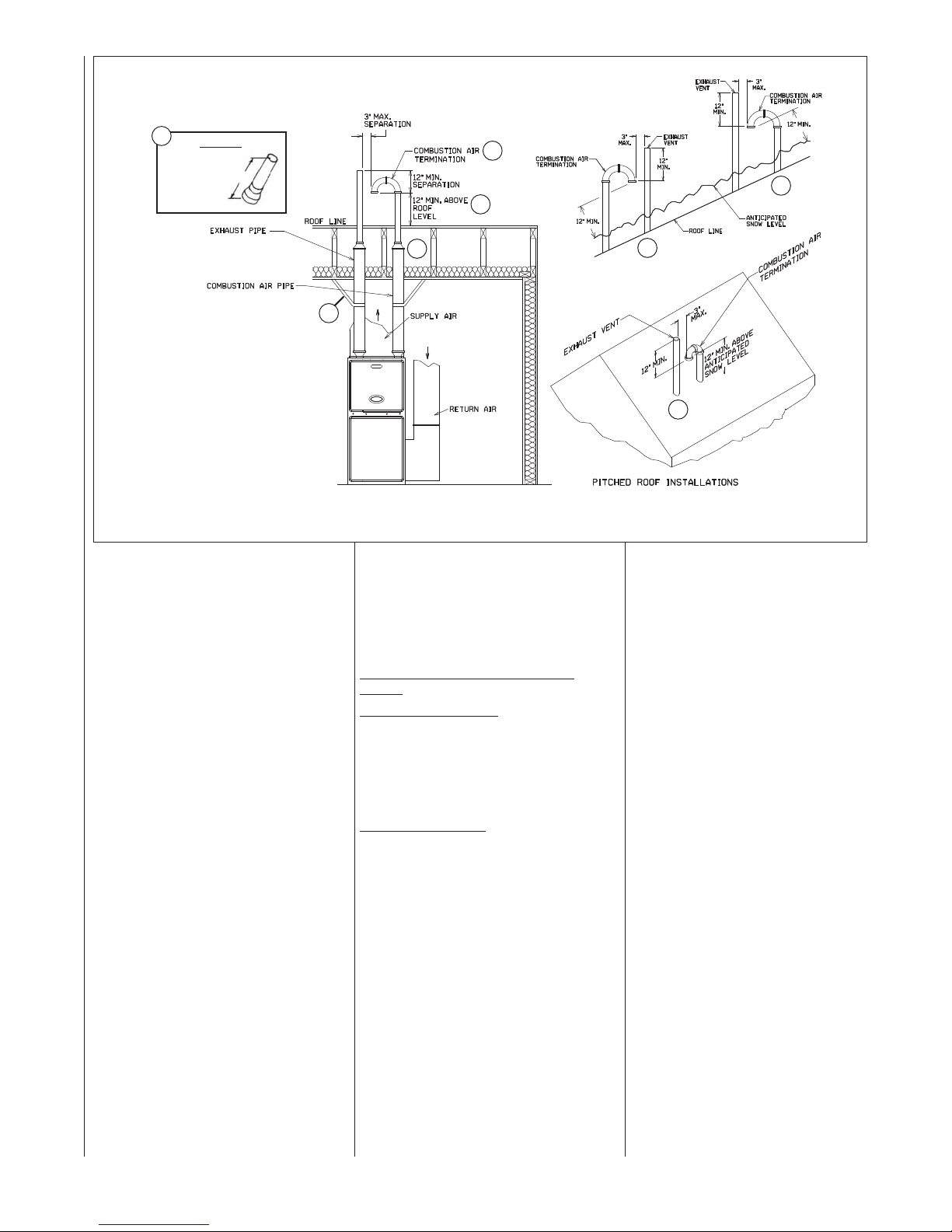
FIGURE 17
STANDARD VERTICAL DIRECT VENTING
UPFLOW MODEL SHOWN (TYPICAL FOR DOWNFLOW/HORIZONTAL MODELS)
5
DETAIL A
EXHAUST
TERMINATION
12”
1
2
5
NOTES:
THE COMBUSTION AIR PIPE
1
MUST TERMINATE IN THE
SAME PRESSURE ZONE AS
THE EXHAUST PIPE.
INCREASE THE 12-IN. MINIMUM
2
TO KEEP TERMINAL OPENING ABOVE
ANTICIPATED LEVEL OF SNOW ACCUMULATIONWHERE APPLICABLE.
WHEN 3-IN. DIAM. PIPE IS USED,
3
REDUCE TO 2-IN. DIAMETER BEFORE
PENETRATING ROOF. A MAXIMUM OF
18 IN. OF 2-IN. PIPE MAY BE USED
BEFORE PASSINGTHROUGH ROOF.
SUPPORT VERTICAL PIPE EVERY 6
4
FEET.
EXHAUSTTERMINATION - TERMINATE
5
THE LAST 12 INCHES WITH 2” PVC
PIPE ON 90,000 AND 120,000 BTUH
MODELS. REDUCE AND TERMINATE
THE LAST 12 INCHES WITH 1
PIPE ON 60,000 THROUGH 75,000 BTUH
MODELS.
SEE DETAIL A.
1
/2” PVC
5. Insulate all vent runs through
unconditioned spaces where
below-freezing temperatures are
expected with 1" thick medium
density, foil faced fiber glass or
equivalent Rubatex/Armaflex insulation. For horizontal runs where
water may collect, wrap the vent
pipe with self-regulating, 3 or 5
Watt heat tape. The heat tape
must be U.L. listed and installed
per the manufacturer’s instructions.
6. All piping between the furnace
and the roof or outside wall pe
tration is 2" or 3" as specified in
Table 7. Table 7 lists the maxi-
mum allowable length for the
exhaust vent pipe and intake air
pipe for the number of elbows
used, based on the type of termi-
nation and furnace size.
7. The minimum vent length is 5
feet.
8. All piping through the roof or outside wall is 2". When using 3"
pipe, reduce to 2" within 18" of
the inside of the roof or outside
wall (except 120,000 BTUH
model using the RXGY-D04 or
D04A Horizontal Vent Kit).
9. Terminate the vent using one of
the following termination options.
ne-
3
4
10. Elbows must be a minimum of 15”
apart.
11. No screens may be used to cover
combustion air or exhaust.
VERTICAL TERMINATIONS
STANDARD VERTICAL TERMINATIONS
Combustion Air Piping
um-radius sweep elbows to keep the
inlet downward and prevent the entry of
rain. The inlet opening of the com-
bustion air termination must be a
minimum of 12" above the anticipated level of snow accumulation.
Exhaust Vent Piping
must terminate at least 12 inches
above the combustion air termination
inlet. The 2" vent pipe used to penetrate the roof must be reduced to 1 1/2"
PVC for the last 12" for the 60,000 and
75,000 BTUH furnace models. No
reduction of the 2" pipe is necessary for
the 90,000 through 120,000 BTUH
models. The maximum length of the
exposed vent pipe above the roof is
30".
(See Figure 16)
: Use two medi-
: The exhaust vent
5
5
ST-A0407-00
25
Page 26

CONCENTRIC TERMINATIONS
CONCENTRIC VENT KIT
NO. RXGY-E03A (SEE FIGURE 18)
This kit is for vertical and horizontal
intake air/vent runs. One
5-in. diameter hole is required for
installation. See Figure 18 for the general layout. Complete installation
instructions are included with the kit.
FIGURE 18
CONCENTRIC VENT KIT NO. RXGY-E03A
(DIRECT VENT INSTALLATIONS)
ITEM No. DESCRIPTION
1 2.5
24
33
43
5 PVC RAINCAP
" PVC PIPE SCHEDULE 40 -- 37.125" LONG
" PVC PIPE SCHEDULE 40 -- 24" LONG
" x3" x4" SPECIAL CONCENTRIC FITTING
" x 45° STREET ELBOW (FIELD SUPPLIED)
NOTE: The following IPEX brand concentric terminations (System 636) may
be purchased in the field
and used in
place of factory supplied kits:
3” Concentric Kit – Item # 196006
VERTICAL INSTALLATION
MAINTAIN 12 IN.
MINIMUM CLEARANCE
ABOVE HIGHEST
ANTICIPATED SNOW
LEVEL. MAXIMUM OF
24 IN. ABOVE ROOF.
HORIZONTAL INSTALLATION
FIELD-SUPPLIED
STRAP
A
NOTE: AIR INTAKE NOT
ORIENTATION SENSITIVE.
1" MAXIMUM
A
A
NOTE: Drain tee is not needed for the inlet pipe.
26
Page 27
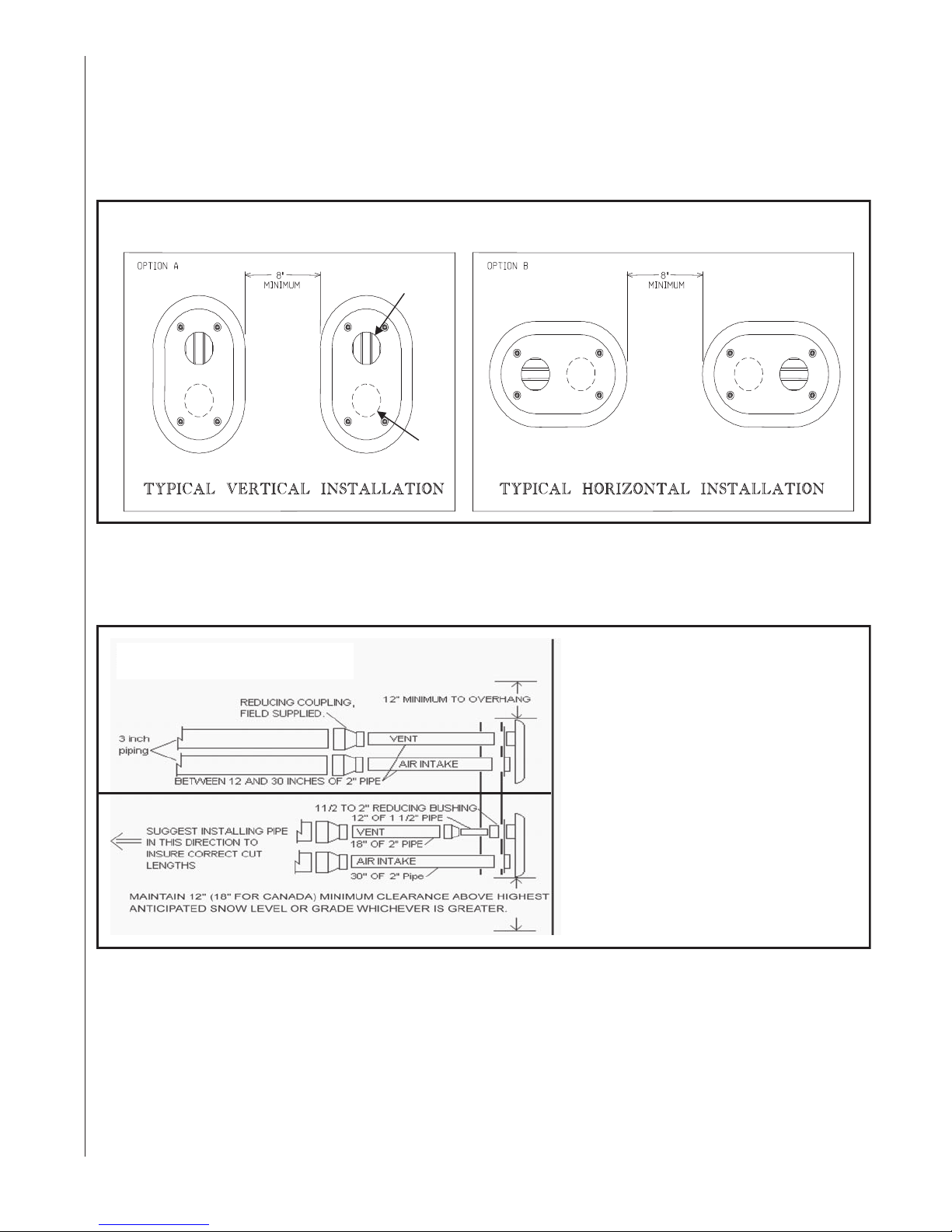
?
INSTALLATION – RXGY-G02A Side Wall Vent
INSTALLATION – RXGY-G02 Side Wall Vent
This termination for horizontal venting only.
This termination for direct vent application only.
Important: Do no install on the prevailing winter wind side of the structure
Note: Multi-venting-No common venting.
FIGURE 19
?
VENT KIT INSTALLATION OPTIONS
?? ? ?
EXHAUST
AIR
INTAKE
NOTE: Install the vent and air intake piping into the vent plate openings. Seal all gaps between the
pipes and wall. Be Sure To Use Silicone Sealant to seal the vent pipe to the vent cap to permit field
disassembly for annual inspection and cleaning. Also seal all pipe penetrations in wall. To prevent
possibility of condensate freeze-up or recirculation, do not install vent kits one above the other.
FIGURE 20
TYPICAL INSTALLATION
For 90000 thru 120000 BTUH modelsreduce to a length between 12 inches
and 30 inches of 2 inch pipe.
For 60000 thru 75000 BTUH modelswhen 3 inch pipe is used: reduce last 30
inches to 18 inches of 2 inch pipe and
12 inches of 1-1/2 inch pipe to maintain
velocity.
Note: Vent should protrude a
maximum of 2-1/4” beyond vent plate.
Air intake should protrude a maximum
of 1inch beyond vent plate.
Seal all wall cavities
ST-A1075
27
Page 28
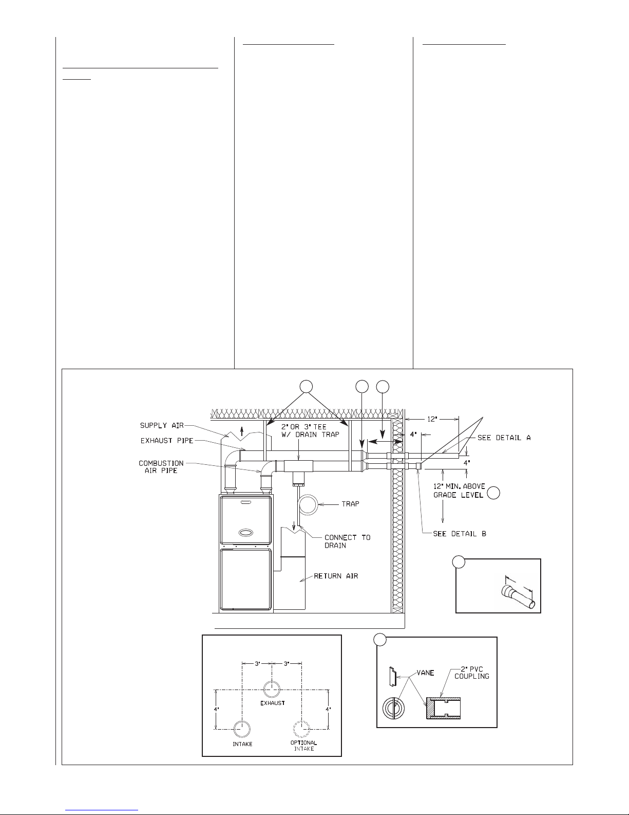
HORIZONTAL TERMINATIONS
STANDARD HORIZONTAL TERMINA-
(SEE FIGURE 21)
TIONS
NOTE: All furnaces with horizontal air
intakes (except those using horizontal
concentric vent kit RXGY-E03A) must
have a drain tee assembly and trap
installed in the combustion air pipe as
close to the furnace as possible. This is
to drain any water that may enter the
combustion air pipe to prevent it from
entering the furnace vestibule area.
These parts are included in horizontal
vent kits RXGY-D02A, RXGY-D03A and
RXGY-D04A.
NOTE: The combustion air and exhaust
terminations must be at least 12 inches
above grade or anticipated snow levels.
Use alternate horizontal terminations
when termination locations are limited
and higher snow levels are anticipated.
NOTE: Ensure the location of the combustion air inlet with respect to the
exhaust vent terminal complies with
Figure 21, detail C.
Combustion Air Piping
: Use a 2" PVC
coupling with a wind deflector vane (provided) installed as follows:
1. Install a 2" coupling to the combustion air pipe at the outside wall to
prevent the termination from being
pushed inward.
2. Cut a 2 1/4" length of 2" PVC pipe
and connect this to the coupling.
3. Connect another 2" coupling to the
end of the 2 1/4" length of pipe.
Terminate this outer coupling 4
inches from the wall.
4. Attach the vane in the final 2" coupling in the vertical position with
PVC cement.
IMPORTANT: To insure proper furnace operation, install the vane in the
vertical position as shown in Figure
21, Detail B. Failure to install the vane
properly can result in nuisance tripping of the pressure switch.
Exhaust Vent Piping:
60,000 and 75,000 BTUH models:
Install a 2" to 1 1/2" reducer coupling at the outside wall to prevent
the termination from being pushed
inward. Reduce the 2" vent pipe
used to penetrate the wall to 1 1/2"
PVC for the last 12" of the run.
Terminate the 1 1/2" PVC exhaust
vent at least 12 inches from the outside wall.
90,000 through 120,000 BTUH
models: Install a 2" coupling at the
outside wall to prevent the termination from being pushed inward. No
reduction of the 2" pipe used to
penetrate the wall is necessary.
Terminate the 2" PVC exhaust vent
at least 12 inches from the outside
wall.
FIGURE 21
STANDARD HORIZONTAL DIRECT VENTING
UPFLOW MODEL SHOWN
(TYPICAL FOR DOWNFLOW/HORIZONTAL MODELS)
NOTES:
SUPPORT HORIZONTAL
➀
PIPE EVERY FOUR FEET.
WHEN 3 IN. PIPE IS USED REDUCE TO
➁
2 IN. BEFORE PENETRATING OUTSIDE WALL.
18 IN. MAXIMUM. 2 IN. DIAMETER
➂
PIPE MAY BE USED INSIDE THE
WALL.
DETAIL“A” - EXHAUSTTERMINATION
➃
TERMINATETHE LAST 12 INCHES
WITH 2” PVC PIPE ON 90,000 AND
120,000 BTUH MODELS. REDUCE
AND TERMINATE THE LAST 12 INCH-
1
/2” PVC PIPE ON 60,000
ES WITH 1
THROUGH 75,000 BTUH MODELS.
INCREASE THE 12 IN. MINIMUM
➄
ABOVE GRADE TO KEEP TERMINAL
OPENINGS ABOVE ANTICIPATE D
LEVEL OF SNOW ACCUMULATION
WHERE APPLICABLE.
DETAIL“B”, INSTALLWIND DEFLEC-
➅
TOR VANE IN 2 IN. PVC COUPLING IN
VERTICAL POSITION USING PVC
SOLVENT.
THE COMBUSTION AIR TERMINATION
MUST BE IN THE SAME PRESSURE
ZONE AS THE EXHAUSTTERMINATION.
EXHAUST/INTAKE RELATIONSHIP
DETAIL C
1
2
3
NO SCREENS OR ELBOWS
AT THE END OF THE PIPES
DETAIL C
5
4
DETAIL A
12”
EXHAUST
TERMINATION
6
COMBUSTION AIR TERMINATION
DETAIL B
ST-A0407-00
28
Page 29
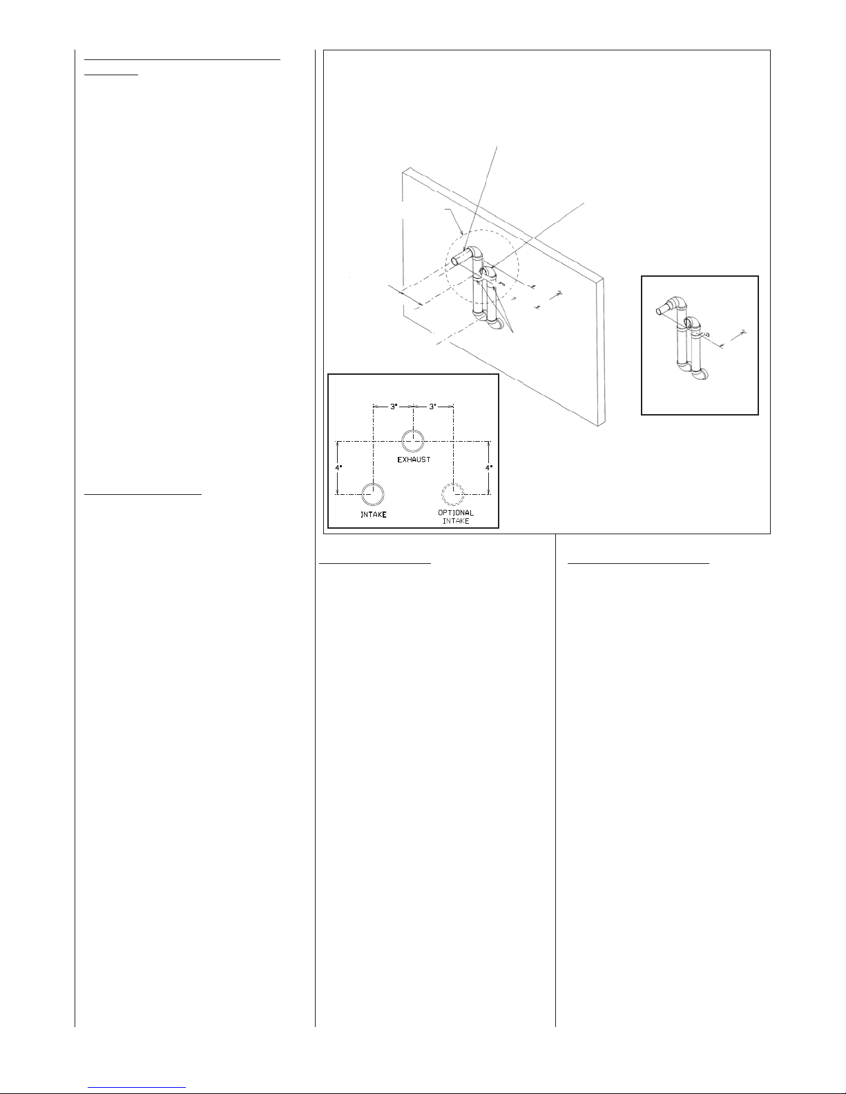
ALTERNATE HORIZONTAL TERMINATIONS (See Figure 22)
NOTE: This method is not permitted
on modulation downflow/horizontal
(RGGE or RGJF) models.
NOTE: The combustion air and
exhaust terminations must be at least
12 inches above grade or anticipated
snow levels. Alternate horizontal ter-
minations allow the combustion air
and exhaust terminations to be raised
a maximum of 60 inches above the
wall penetrations to maintain the
required clearance.
NOTE: If combustion air vent pipe is
extended more than 24 inches, insulate the vent pipe between the two
outside 90° elbows with closed cell
insulation such as rubatex, armaflex
or equivalent.
NOTE: Ensure the location of the
combustion air inlet with respect to
the exhaust vent terminal complies
with Figure 22.
Combustion Air Piping
: Use a 2" PVC
elbow with a wind deflector vane (provided) installed as follows:
1. Install a 2" elbow to the combustion
air pipe at the outside wall to prevent
the termination from being pushed
inward.
2. Cut an adequate length of 2" PVC
pipe as needed to clear the anticipated snow level and connect this to
the elbow.
3. Connect another 2" elbow to the
end of the pipe such that the inlet is
facing away from the wall. This outer
coupling must terminate 4 inches
from the wall.
4. Attach
the vane in the final 2" elbow
in the vertical position with PVC
solvent.
IMPORTANT: To insure proper furnace operation, the supplied vane
must be installed in the vertical position as shown in Figure 21, Detail B.
FIGURE 22
ALTERNATE HORIZONTAL DIRECT VENTTERMINATION
SEE DETAIL A
3" MAX.
NOTE: 3-1/2"
MAX. WHEN
D04 KIT IS
USED.
EXHAUST VENT
21/2" PVC FOR MODELS WITH 120,000 BTUH INPUT
(KIT NO. RXGY-D04A)
2" PVC FOR MODELS WITH INPUTS OF 90,000 THRU 120,000
BTUH. REDUCE TO 11/2" FOR MODELS WITH INPUTS OF 60,000
AND 75,000 BTUH. ELBOWS AND RISERS ARE 2" PVC.
12" FROM WALL
PIPE
SUPPORT
STRAP
DETAIL C
EXHAUST/INTAKE RELATIONSHIP
NOTE: If combustion air vent pipe is extended more
than 24 inches, insulate the vent pipes between the
two outside 90° elbows with closed cell insulation
such as rubatex, armaflex, or equivalent.
Exhaust Vent Piping
:
1. Install a 2" elbow to the exhaust vent
pipe at the outside wall to prevent the
termination from being pushed
inward.
2. Cut an adequate length of 2" PVC
pipe as needed to insure proper loca-
tion of the exhaust vent termination
with respect to the combustion air
inlet and connect this to the elbow.
3. Connect another 2" elbow to the end
of the pipe such that the inlet is facing away from the wall.
INTAKEVENT
21/2" PVC FOR MODELS WITH
120,000 BTUH INPUT.
2" PVC ELBOWS AND RISER
MODELS WITH INPUTS OF 75,000
THRU 120,000 BTUH.
USE KIT NO. RXGY-D02 OR D02A WHEN 2"
PIPE IS USED BETWEEN FURNACE AND
OUTSIDE WALL. USE KIT NO. RXGY-D03
OR D03A WHEN 3" PIPE IS USED.
DETAIL A
EXHAUST VENT FOR
MODELS WITH INPUT OF
60,000 AND 75,000 BTU
I339
Exhaust Vent Termination:
60,000 and 75,000 BTUH models:
Reduce the 2" vent pipe used to
penetrate the wall and extend the
terminations to 1 1/2" PVC for the
last 12" of the run. Install a 2" to 1
1/2" reducer bushing in the last 2"
elbow. Connect a length of 1 1/2"
PVC pipe such that the exhaust vent
terminates at least 12 inches from
the outside wall. See Figure 22,
Detail A.
90,000 through 120,000 BTUH models: No reduction of the 2" pipe used
to penetrate the wall is necessary.
Terminate the 2" PVC exhaust vent
at least 12 inches from the outside
wall.
120,000 BTUH model with the
RXGY-D04A Horizontal Vent Kit:
Venting and terminations install the
same as above except the 2" pipe
and connectors are replaced with 2
1/2" pipe and connectors.
29
Page 30
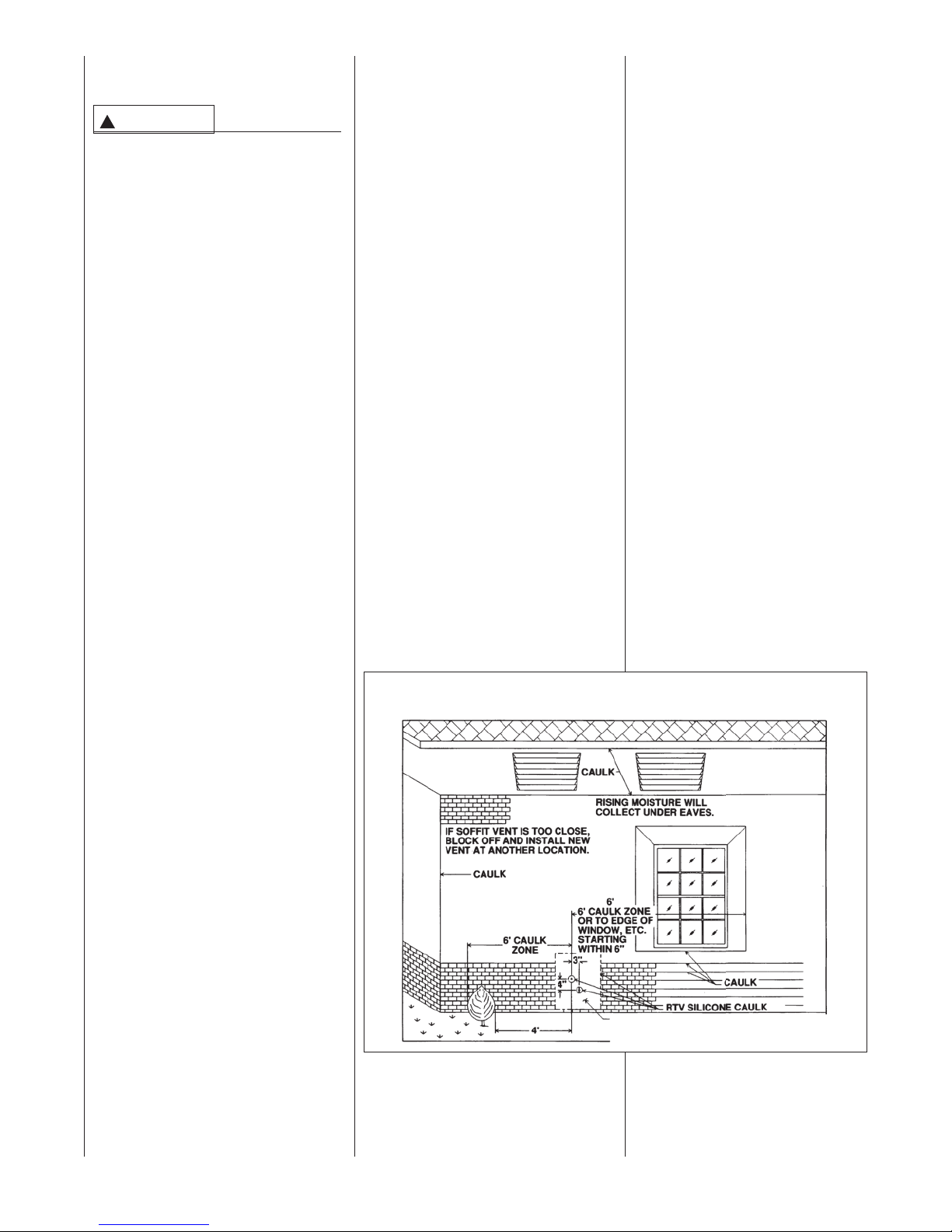
LOCATION REQUIREMENTS
HORIZONTAL DIRECT VENTS
CAUTION
!
THE COMBUSTION PRODUCTS
AND MOISTURE IN THE FLUE
GASES WILL CONDENSE AS
THEY LEAVETHE TERMINATION.
THE CONDENSATE CAN FREEZE
ON THE EXTERIOR WALL,
UNDER THE EAVES AND ON
SURROUNDING OBJECTS.
SOME DISCOLORATIONTOTHE
EXTERIOR OF THE BUILDING IS
TO BE EXPECTED. HOWEVER,
IMPROPER LOCATION OR
INSTALLATION CAN RESULT IN
STRUCTURAL OR EXTERIOR
FINISH DAMAGETOTHE BUILDING AND MAY RECIRCULATE
PRODUCTS OF COMBUSTION
INTOTHE COMBUSTION AIR
TERMINAL AND FREEZE.
NOTE: In Canada vent terminations
must be in accordance with the current
CSA-B149 Gas Installation Code and/or
local codes.
The vent must be installed with the following minimum clearances. See
Figures 23 and 24.
1. Locate the bottom of the vent terminal and the air inlet at least 12
inches above grade. Increase the
12-in. minimum to keep the terminal openings above the level of
snow accumulation, where applicable.
2. Do not terminate the vent over public walkways or over an area where
condensate or vapor could create a
nuisance or hazard.
3. Locate the vent terminal at least
one foot from any opening through
which flue gases could enter a
building.
4. Locate the vent terminal at least 3
feet above any forced air inlet
located within 10 feet, except the
combustion air inlet of a direct vent
appliance.
5. Allow the vent terminal minimum
horizontal clearance of 4 feet from
electric meters, gas meters, regulators and relief equipment.
6. Locate the furnace combustion air
inlet a sufficient distance from the
vent of any other gas or fuel burning appliance or electric clothes
dryer to prevent recirculation of the
flue gases into the furnace com-
bustion air inlet. The only exception
to this requirement is the case of
multiventing two or more furnaces,
which is covered in the section on
multiventing in these instructions.
In addition to the minimum clearances
listed above, the ven
be governed by the following guidelines.
1. Do not terminate under any kind of
patio or deck. If running the vent
under a deck, insulate it to insure
no condensate freezes and blocks
the pipe. The insulation must be
waterproof.
For vent considerations, the edge
of the deck must be considered
the outside wall.
2. Do not terminate behind any area
that may allow the flue products to
become stagnant and recirculate.
3. Do not locate on the side of a
building with pre
winds. This will help prevent mois-
ture from freezing on walls and
overhangs (under eaves).
4. Do not extend vent directly
through brick or masonry surfaces. Use a rust-resistant sheet
metal or plastic backing plate
behind vent. See Figure 15.
5. Do not locate too close to shrubs
as condensate may stunt or
kill them.
FIGURE 23
MOISTURE ZONES
t location should
vailing winter
6. Minimum vertical clearances of 1
foot are recommended for over-
hangs up to 1 foot horizontal.
The vertical clearance should be
increased equ
tional increase in horizontal overhang to a maximum vertical
clearance of 6 feet.
7. Caulk all cracks, seams and
joints within 6 feet horizontally
as well as 6 feet above and
below vent. See Figure 23.
8. Painted surfaces must be sound
and in good condition with no
cracking, peeling, etc. Painted
surfaces will require maintenance.
9. Do not expose 3" x 2" reducer/
bushing to outdoor ambient temperatures.
ally for each addi-
MULTIVENTING
IF VENTINGTWO OR MORE FURNACES NEAR EACH OTHER IS
REQUIRED, EACH FURNACE
MUST BE INDIVIDUALLY VENTED –
NO COMMON VENTING IS PERMITTED. See Figures 25 and 26 for posi-
tioning of the terminations. When
2 FT. SQ. SHEET METAL PLATE ON BRICK OR
MASONRY SURFACE RECOMMENDED, BUT
NOT REQUIRED BY CODE.
30
Page 31

FIGURE 24
DIRECT VENTTERMINAL CLEARANCES
US Installations
National Fuel Gas Code
Canadian Installations
US Installations
Natural Gas and Propane Installation Code
Canadian Installations
31
Page 32

FIGURE 25
TWO FURNACE VENTINGTHROUGH ROOF
FIGURE 26
TWO FURNACE VENTINGTHROUGH WALL
TWO-PIPE VENTING
EXHAUST VENT
MODELS 06-07
TO BE REDUCED TO
1-1/2” PVC LAST 12”.
3” MININUM
24” MAXIMUM
CONCENTRIC VENTING
8” MININUM
24” MAXIMUM
8"
TWO-PIPE VENTING
3” MININUM
24” MAXIMUM
CONCENTRIC VENTING
SEE CONCENTRIC
MINIMUM 12" ABOVE AVERAGE
SNOW ACCUMULATION. MAXIMUM
OF 24 IN. ABOVE ROOF.
VENT SECTION
ON PAGE 23
FOR MORE
INFORMATION.
more than two furnaces are to be
vented, there must be at least 4 feet
between the first two furnaces and
the third, etc.
CONNECTING TO
FURNACE
IMPORTANT: Clean and deburr all
pipe cuts. The shavings must not be
allowed to block the exhaust, inlet or
condensate drain pipes.
IMPORTANT: When indoor combus-
tion air is used, the inlet air opening
at the furnace must be protected from
accidental blockage. On downflow
models, install a doub
top inlet air opening. See Figure 30.
le elbow in the
MAXIMUM 1"
DISTANCE
FROM WALL
8” MININUM
24” MAXIMUM
UPFLOW MODELS
The exhaust air pipe connection is a
2-in. female PVC pipe fitting extend-
ing through the left
nace top plate. See Figure 27. This
opening has a protective cap which
should be removed just prior to
installing the exhaust pipe. When 2-
in. pipe is used, connect it directly to
this fitting. When 3-in. pipe is used,
connect a 2 to 3-in. coupling to this
fitting with a short piece of 2-in. PVC
pipe.
The inlet combustion air connection
is at the right
An alternate combustion inlet air connection may be made on the right
side of the jacket. The alternate con-
side of the fur-
side of the top plate.
6' MINIMUM
10' RECOMMENDED
MINIMUM 12"
ABOVE GRADE
8"
SEE CONCENTRIC VENT SECTION
ON PAGE 23 FOR MORE INFORMATION.
nection opening has a plastic cap. A
combustion inlet air connection fitting
is supplied with the furnace and it
must be installed in the furnace by
screwing it into the opening. Make
sure the rubber “O-ring” supplied with
the furnace is used with this fitting.
See Figure 27.
IMPORTANT: When using indoor
combustion air, the furnace air opening must be protected from accidental
blockage. In
pointing downward on the side or a
double elbow pointing downward in
the top opening. See Figure 28.
stall a 2-inch 90° elbow
32
Page 33

➤DOWNFLOW/HORIZONTAL
MODELS
NOTE: Combustion air inlet and exhaust
outlet air pipes are reversed for down-
flow and horizontal models from that of
upflow.
The exhaust pipe connection is a 2-in.
PVC pipe fitting extending through the
right side of the furnace top cover. This
opening has a protective cap which
should be removed just prior to installing
the exhaust pipe. When 2-in. pipe is
used, connect it directly to this fitt
When 3-in. pipe is used, connect with a
2- to 3-in. coupling directly to the 2-in.
pipe.
The combustion inlet air connection is a
2-in. extruded hole on the left side of the
top plate. When a 2-in. pipe is used,
attach a 2-in. PVC coupling over this
hole with RTV sealant and also add two
sheet metal screws through the coupling
into the extrusion to secure it in place,
and add the required piping. When 3-in.
pipe is required, use a 2- to 3-in. cou-
pling and add the required piping. S
Figure 29.
IMPORTANT: Always pre-drill holes
before securing with screws. Using selftapping screws without first pre-drilling
causes the PVC fitting to crack.
ing.
ee
FIGURE 27
UPFLOW COMBUSTION AIR AND VENT PIPE CONNECTION
(GAS VALVE MAY BE DIFFERENT THAN SHOWN)
TOP PLATE
VENT CAP/PLUG
OUTLET AIR PIPE
EXHAUST TRANSITION
CONNECTOR
CONDENSATE TRAP
FIGURE 28
DOWNFLOW COMBUSTION AIR AND VENT PIPE CONNECTION
(GAS VALVE MAY BE DIFFERENT THAN SHOWN)
NOTE:
ATTACH COUPLING TO EXTRUDED
COLLAR WITH TWO SCREWS. PUT
BEAD OF SILICONE AROUND BASE
BEFORE MOUNTING COUPLING.
COMBUSTION
AIR CHASE
“O” RING
TOP PLATE
COUPLING
COMBUSTION
AIR ADAPTER
NOTE:
WHEN COMBUSTION AIR INLET IS IN
OPTIONAL POSITION SWAP LOCATION
OF INLET AIR ADAPTER AND “O” RING
WITH PLUG.
PLUG OPT. COMBUSTION
AIR INLET POSITION
INDUCED DRAFT
BLOWER
A1119-01_1
VENT CAP/PLUG
EXHAUST AIR
PIPE - PVC
CONNECTOR
FIGURE 29
UPFLOW MODELS -- COMBUSTION AIR FITTING
INDUCED DRAFT
BLOWER
OUTLET AIR PIPE
EXHAUST TRANSITION
A1119-01_2
➤ FIGURE 30
DOWNFLOW/HORIZONTAL MODELS COMBUSTION AIR AND VENT PIPE CONNECTION
33
Page 34

CONDENSATE DRAIN/OPTIONAL NEUTRALIZER
GENERAL INFORMATION
CAUTION
!
DO NOT RUN DRAIN OUTDOORS.
FREEZING OF CONDENSATE CAN
CAUSE PROPERTY DAMAGE.
IMPORTANT: Do not connect into a com-
mon drain line with an air conditioner
evaporator coil drain located below the
furnace. A blocked or restricted drain line
can result in overflow of the coil pan and
negate the furnace blocked-drain shutoff
control.
➤ IMPORTANT: If installing the unit over
a finished ceiling or living area, be certain
to install an auxiliary condensate drain
pan under the entire unit extending out
under the condensate tee. With the mini-
1
mum 5
⁄2" riser for upflow models
or 13⁄4" for downflow models installed
above the tee, a blocked drain will result
in overflow from the riser. if the furnace is
installed in an attic, crawlspace or other
area where freezing temperatures may
occur, the furnace drain can freeze while
shut off for long periods of time.
If required by local codes, install a con-
densate neutralizer cartridge in the drain
line. Install cartridge in horizontal position
only.Also install an overflow line if routing
to a floor drain (see Figures 31 & 32). If
available, install a condensate pump that
is resistant to acidic water. Pumps are
available from your local distributor. If
pump used is not resistant to acidic water,
a condensate neutralizer must be used
ahead of the pump. The condensate
pump must have an auxiliary safety
switch to prevent operation of the furnace
and resulting overflow of condensate in
the event of pump failure. The safety
switch must be wired through the “R” circuit only (low voltage) to provide operation
in either heating or cooling modes.
When selecting neutralizer cartridges and
condensate pumps, use the following
data:
CONDENSATE PRODUCTION:
MAX (ALL MODELS) = 1-2 gallons per hr.
FIGURE 31
UPFLOW CONDENSATE DRAIN
(GAS VALVE MAY BE DIFFERENT THAN SHOWN)
➤ FIGURE 32
DOWNFLOW CONNECTION
(GAS VALVE MAY BE DIFFERENT THAN SHOWN)
A1120.01_1
pH LEVEL:
3.2 - 4.5 using OUTDOOR air
2.2 - 4.5 using INDOOR air
(neutral pH = 7.0)
UPFLOW MODELS
The condensate drain trap is located in
the blower compartment on the left- hand
side of the jacket. A short piece of1⁄2-in.
PVC pipe and a1⁄2-in. tee are provided.
Connect the1⁄2-in. pipe to the elbow on
the trap and the tee to this pipe so that
the open end is upward. Run a drain tube
from the bottom of the tee to a floor drain
or condensate pump.
IMPORTANT: If installing the unit over a
finished ceiling or living area, be certain
to install an auxiliary condensate drain
pan under the entire unit extending out
under the condensate tee.
34
A1120.01_2
Page 35

IMPORTANT: There are two options
when choosing a height for the condensate riser:
CONDENSATE OVERFLOW:With a
1
5
⁄2 inch riser installed above the tee,
a blocked drain will result in overflow
from the riser.
FURNACE SHUTDOWN: To cause
the furnace to shut down when a
blocked drain is present, install a riser
which is a minimum of 10
13
⁄16”. If the
furnace is installed in an attic, crawlspace or other area where freezing
temperatures may occur, the furnace
drain can freeze while shut off for long
periods of time.
Use a solvent cement that is compatible with PVC material. Cut the drain
hoses to the appropriate length and
connect to the trap with hose clamps.
Tighten the clamps with pliers and
check for leaks after attaching.
DOWNFLOW MODELS
IMPORTANT: There are two options
when choosing a height for the condensate riser:
CONDENSATE OVERFLOW:With a
3
1
⁄4 inch riser installed above the tee,
a blocked drain will result in overflow
from the riser.
FURNACE SHUTDOWN: To cause
the furnace to shut down when a
blocked drain is present, install a riser
which is a minimum of 5
1
⁄2”. If the fur-
nace is installed in an attic, crawlspace or other area where freezing
temperatures may occur, the furnace
drain can freeze while shut off for long
periods of time.
Use a solvent cement that is compatible with PVC material.
RXGY-H01
CONVERTING TO LEFT
DRAIN FOR DOWNFLOW
MODELS
To convert downflow models to lefthand drain, a kit (RXGY-H01) must be
ordered from the distributor. The kit
includes a 24” piece of1⁄2” black PVC
pipe, a 2” rubber grommet, a 1-5/8”
plug and instructions. Note the location of the alternate drain hole as
shown in Figure 34.
To convert to left side drainage, first
remove the drainage hoses from the
trap. Remove the trap from its mounting bracket, rotate it 180 degrees and
mount in place with the drainage
elbow pointing to the left. Reattach the
drain hoses.
Remove the plug from the 2” alternate
drain hole (see Figure 34) and replace
it with the 2” rubber grommet supplied
in the RXGY- H01 downflow alternate
diameter plug that is also supplied in
the RXGY-H01 downflow alternate
drain kit. Both the hole-plug and
grommet must be in place to insure a
good seal in the burner compartment.
A length of
provided in the RXGY-H01 downflow
alternate drain kit. Glue one end of
the pipe to the elbow in the trap. Cut
the pipe so that it extends through
the alternate drain hole in the left side
of the cabinet one inch (see Figure
34). Connect the1/2” PVC tee (supplied with the furnace) to the pipe
with a 1-3/4” riser. Use the 1-5/8”
plug supplied in the RXGY-H01
downflow alternate drain kit to seal
the right side drainage hole.
IMPORTANT: Do not connect into a
common drain line with an air conditioner evaporator coil drain located
above the furnace. A blocked or
restricted drain line can result in overflow of the coil pan and negate the
furnace blocked-drain shutoff control.
drain kit. Also, remove the 1-5/8”
grommet supplied in the primary drain
hole and replace it with the 1-5/8”
FIGURE 33
UPFLOW OPPOSITE SIDE CONDENSATETRAP CONNECTION
(NO KIT REQUIRED)
1
/2” black PVC pipe is also
REVERSING THE TRAP
UPFLOW MODELS
The trap may be moved to the right
side for right-side drainage. Open the
knockout for the drain on the right side
of the cabinet. Remove the bracket
holding the trap from the left side.
Seal the left side drain hole with a
plug provided in the cloth bag with the
furnace. Position the mounting bracket
and trap so that the drain elbow is
centered in the hole on the right. See
Figure 33.
Drill two holes in the cabinet to mount
the bracket. Mount the trap and bracket to the right side with the drain
elbow pointing through the knockout.
Connect the
above. Route the drain hoses behind
the top of the electric box, cut to the
appropriate length, and connect to the
trap with hose clamps.
IMPORTANT: Do not connect into a
common drain line with an air conditioner evaporator coil drain located
above the furnace. A blocked or
restricted drain line can result in overflow of the coil pan and negate the
furnace blocked drain shutoff control.
1
⁄2" pipe and tee as noted
ST-A1121-01
FIGURE 34
DOWNFLOW OPPOSITE SIDE CONDENSATE TRAP CONNECTION
(REQUIRES RXGY-H01 KIT) (GAS VALVE MAY BE DIFFERENT THAN SHOWN)
ST-A1121-01
35
Page 36

CONVERTING DOWNFLOW/HORIZONTAL (RGGE WITH HB
FUEL CODE ONLY) MODELS TO HORIZONTAL CONFIGU-
See additional instructions
on page 38 for instructions on installing the trap
for dedicated horizontal
models (RGJF only)
CONDENSATE DRAIN
FOR HORIZONTAL
INSTALLATION
NOTE: Only RGGE models with HB
fuel codes can be installed in the hori-
zontal configuration. All other fuel gas
codes must be installed as dedicated
downflow configuration only.
Refer to Figure 36 for Steps 1-5.
1. This unit is shipped factory ready
for downflow
densate trap assembly and drain
hoses require conversion for hori-
zontal installation. Remove the
existing condensate trap with the
unit in the upright
IMPORTANT: This furnace may
only be installed so that when facing the front of the furnace, supply
air is discharged on the left hand
side.
2. Remove the burner compartment
door from the unit.
3. Remove the two screws from the
right side of the furnace jacket
which support the trap mounting
bracket ➁. Remove the two plastic plugs on either side of the trap
outlet hole and discard.
4. Remove the (L-shaped) clear
vinyl drain tube ➂ from the top of
the existing trap ➀.
Do no
from the furnace collector box.
5. Remove the ribbed drain tube ➃
from the existing trap ➀ and the
exhaust transition ➄. Discard this
tube. Retain the clamps for future
use. Additional clamps are provided in the parts bag if any clamps
are damaged during conversion
process.
NOTE: The following steps should
take place with the furnace in the hori-
zontal position.
Refer to Figure 37 for Steps 6-11.
6. Locate the parts bag in the burner
compartment. Inst
plugs ➅ in the side of the jacket
from bottom side up.
installation. The con-
position.
t
disconnect the short end
all two plastic
7. Fill the trap assembly ➆ with 1/2
cup of water.
8. Attach the gasket ➇ onto the trap
assembly so that the gasket holes
on the gasket line up with the
holes on the trap assembly.
9. Insert the trap assembly with gas-
ket up through the existing hole in
the jacket and secure from inside
the jacket. Use two screws pro-
vided. Screw down into the two
“ears” molded into either side of
the trap. Snug the trap assembly
against the furnace jacket com-
pressing the gasket slightly to
eliminate any air leaks. Do not
overtighten!
10. Attach the black molded rubber
90° elbow ➈ to the straight spout
on the trap top using a black
nylon clamp ➉. Attach the other
end of the rubber elbow to the
11
spout ➋ located on the exhaust
transition ➄ using a black nylon
clamp.
11. Attach the end of the ribbed tube
➂ to the 45° elbow molded into
the top of the trap assembly using
a black nylon clamp.
FIGURE 35
HORIZONTAL CONDENSATE DRAIN
(GAS VALVE, MANIFOLD AND PRESSURE
SWITCHES MAY BE DIFFERENT THAN
SHOWN)
IMPORTANT: Tighten all clamp
connections with a pair of pliers
and check for leaks after conversion is complete.
12. IMPORTANT: There are two
options when choosing a height
for the condensate riser:
CONDENSATE OVERFLOW:
With a 1
above the tee, a blocked drain
will result in overflow from the
riser.
FURNACE SHUTDOWN: To
cause the furnace to shut down
when a blocked drain is present,
install a riser which is a minimum
of 5
in an attic, crawlspace or other
area where freezing tempera-
tures may occur, the furnace
drain can freeze while shut off
for long periods of time.
Use a solvent cement that is
compatible with PVC material.
3
⁄4 inch riser installed
1
⁄2”. If the furnace is installed
ST-A1128-01
36
Page 37

I534
CONDENSATE TRAP CONVERSION FROM DOWNFLOW TO
HORIZONTAL INSTALLATION
FIGURE 37
HORIZONTAL POSITION: CONDENSATE TRAP INSTALLATION FOR HORIZONTAL
OPERATION
FIGURE 36
UPRIGHT POSITION: REMOVAL OF EXISTING DOWNFLOW CONDENSATE TRAP
37
Page 38

CONDENSATE DRAIN
FOR HORIZONTAL
(RGJF) INSTALLATION
WARNING
!
DEDICATED HORIZONTAL (RGJF)
MODELS ARE SHIPPED WITHOUT
A DRAIN TRAP ATTACHED. IT
MUST BE ATTACHED (AS
DESCRIBED BELOW) IN THE
FIELD. FAILURE TO INSTALLTHE
DRAIN TRAP AS DESCRIBED CAN
CAUSETHE FURNACE TO SHUT
DOWN UNEXPECTEDLY.
NOTE:The following steps should
take place with the furnace in the
horizontal position.
Refer to Figure 37 for Steps 1-8.
1. Locate the parts bag in the burner
compartment.
2. Remove the red vinyl covers that
cover the vent drain and heat
exchanger drain (see Figure 38).
3. Fill the trap assembly with a
cup of water.
4. Attach the gasket onto the trap
assembly so that the gasket holes
on the gasket line up with the
holes on the trap assembly.
5. Insert the trap assembly with gas-
ket up through the existing hole in
the jacket and secure from inside
the jacket. Use two screws pro-
vided. Screw down into the two
“ears” molded into either side of
the trap. Snug the trap assembly
against the furnace jacket com-
pressing the gasket slightly to
eliminate any air leaks. Do not
overtighten!
6. Attach the black molded rubber
90° elbow to the straight spout
on the trap top using a black
nylon clamp . Attach the other
end of the rubber elbow to the
spout located on the exhaust
transition using a black nylon
clamp.
7. Attach one end of the horizontal
ribbed tube to the collector box.
Clamp the hose tight with black
nylon clamp. Then attach the
other end of the ribbed tube to the
45° elbow molded into the top of
the trap assembly. Clamp the
hose tight with black nylon clamp.
The horizontal ribbed tube is 6.7”
in length.
IMPORTANT: Tighten all clamp
connections with a pair of pliers
and check for leaks after conversion is complete.
8. IMPORTANT: There are two
options when choosing a height
for the condensate riser:
CONDENSATE OVERFLOW:
With a 13⁄4 inch riser installed
above the tee, a blocked drain will
result in overflow from the riser.
I
J
K
E
L
G
H
FURNACE SHUTDOWN: To
cause the furnace to shut down
when a blocked drain is present,
install a riser which is a minimum
1
of 5
⁄2”. If the furnace is installed
in an attic, crawlspace or other
area where freezing temperatures
may occur, the furnace drain can
freeze while shut off for long periods of time. Provisions must be
made to prevent freezing of condensate.
Use a solvent cement that is compatible with PVC material.
FIGURE 38
REMOVE VINYL CAPS BEFORE INSTALLINGTHE DRAIN SYSTEM.
(-GJF MODELS ONLY)
NOTE: See location requirements
and combustion section for additional
recommendations.
FILLING THE TRAP
FILL THE TRAP ASSEMBLY WITH
WATER BEFORE OPERATINGTHE
FURNACE. Do this by removing the
drain hose from the trap or from the
connection to the secondary coil.
Pour about a cup of water into the
vent trap. Any excess water flows into
the house drain when the trap is full.
REMOVE THESE
RED VINYL
COVERS TO
INSTALL THE
DRAIN SYSTEM
38
Page 39

GAS SUPPLY AND PIPING
GAS SUPPLY
WARNING
!
THIS FURNACE IS EQUIPPED
AT THE FACTORY FOR USE ON
NATURAL GAS ONLY. CONVERSION TO LP GAS REQUIRES A
SPECIAL KIT AVAILABLE FROM
THE DISTRIBUTOR. FAILURE TO
USE THE PROPER CONVERSION KIT CAN CAUSE FIRE,
CARBON MONOXIDE POISONING, EXPLOSION, PROPERTY
DAMAGE, PERSONAL INJURY
OR DEATH.
See the conversion kit index supplied with the furnace. This index
identifies the proper LP Gas
Conversion Kit required for each
particular furnace.
IMPORTANT: Any additions,
or conversions required for the furnace
to satisfactorily meet the application
should be made by a qualified installer,
service agency or the gas supplier,
using factory-specified or approved
parts.
IMPORTANT: Connect this furnace
only to gas supplied by a commercial
utility.
IMPORTANT: A U.L. recognized
fuel gas and CO detector(s) are recommended in all applications, and their
installation should be in accordance
with the manufacturer’s recommendation
s and/or local laws, rules, regula-
tions or customs.
changes
FIGURE 39
GAS PIPING -- UPFLOW INSTALLATION
(GAS VALVE MAY BE DIFFERENT
THAN SHOWN)
MANUAL
GAS VALVE
4 TO 5 F T.
ABOVE FLOOR
REQ’D BY
SOME
UTILITIES.
GROMMET
(IN NORMAL
POSITION)
DRIP LEG
UNION
(TYPICAL INSTALLATION)
TOP VIEW OF GAS LINE AND VALVE
IN OPT. POSITION
BURNERS
GROMMET
NOTE:
WHEN GAS LINE IS IN OPT.
POSITION, SWAP LOCATION
OF GROMMET AND PLUG.
OPTIONAL GAS LINE
POSITION
GAS VALVE
MANIFOLD
PRESSURE TAP
PLUG
(IN NORMAL
POSITION)
MANIFOLD
IMPORTANT: Do not run a flexible gas connector inside the unit.
➤ FIGURE 40
GAS PIPING -- HORIZONTAL INSTALLATION (GAS VALVE, MANIFOLD AND PRESSURE
SWITCHES MAY
BE DIFFERENT
THAN SHOWN)
DRIP LEG
BURNERS
MANUAL GAS VALVE
INSTALLA UNION
BETWEEN THE MANUAL
GAS STOP AND THE MAIN
GAS VALVE
GROMMET
GAS VALVE
NOTE: ONLY RGGE
MODELS WITH
FUEL CODE HB
CAN BE INSTALLED
HORIZONTALLY.
A1122-01_1
GAS PIPING
Install the gas piping according to all
local codes and regulations of the utility company.
If possible, run a separate gas supply
line directly from the meter to the furnace. Consult the local gas company
for the location of the manual main
shut-off valve. The gas line and man-
ual gas valve must be adequate in
size to prevent undue pressure drop
and never smaller than the pipe size
MANIFOLD
MANIFOLD
PRESSURE TAP
A1122-01_2
➤ FIGURE 41
GAS PIPING — DOWNFLOW INSTALLATION (GASVALVE MAY BE DIFFERENT THAN SHOWN)
MANUAL GAS VALVE
4 TO 5 F T.
ABOVE
FLOOR
REQ’D BY
SOME
UTILITIES.
GROMMET
(IN NORMAL
POSITION)
DRIP LEG
TOP VIEW OF GAS LINE AND VALVE
IN OPT. POSITION
UNION
BURNERS
GROMMET
NOTE:
WHEN GAS LINE IS IN OPT.
POSITION, SWAP LOCATION
OF GROMMET AND PLUG.
OPTIONAL GAS
LINE POSITION
GAS VALVE
PLUG
(IN NORMAL
POSITION)
MANIFOLD
PRESSURE
TAP
MANIFOLD
A1122-01_1
39
Page 40

to the combination gas valve on the
furnace. Refer to Table 8 for the recom-
mended gas pipe size for natural gas
and Table 9 for L.P. See Figures 39, 40
& 41 for typical gas pipe connections.
Install a ground joint union between
the manual gas stop and the main
gas valve to easily remove the control valve assembly. Install a manual
gas stop in the gas line outside the
furnace cabinet. The gas stop should
be readily accessible to t
supply on or off. Install a drip leg in the
gas supply line as close to the furnace
as possible. Always use a pipe compound resistant to the action of liquefied
petroleum gases on all threaded connections.
IMPORTANT: When making gas pipe
connections, use a back-up wrench to
prevent any twisting of the control
assembly and gas valve.
Any strains on the gas valve can
change the position of the gas orifices in
the burners. This can cause erratic furnace operation.
IMP
ORTANT: Do not run a flexible gas
connector inside the unit. If local codes
allow the use of a flexible gas appliance
connector, always use a new listed connector. Do not use a connector which
has previously serviced another gas
appliance. Massachusetts law requires
that all flexible gas connectors be less
than 36”.
The gas pipe grommet in the cabinet
does not seal around a flexible gas con-
nector. It is important to have all
openings in the cabinet burner compartment seale
operation.
IMPORTANT: To insure a good seal, the
gas pipe that runs through the grommet
must be 1/2” schedule 40 black pipe.
IMPORTANT: Ensure that the furnace
gas control valve is not subjected to
high gas line supply pressures (13.5”
w.c. or above).
DISCONNECT the furnace and its individual shut-off valve from the gas supply
piping during any pressure testing that
exceeds 1/2 PSIG (3.23 kPa or 13"
w.c.).
d for proper furnace
urn the gas
GAS PRESSURE
Natural gas supply pressure should
be 5" to 10.5" w.c. LP gas supply
pressure should be 11" to 13" w.c.
This pressure must be maintained
with all other gas-fired appliances in
operation.
WARNING
!
NEVER PURGE A GAS LINE INTO
THE COMBUSTION CHAMBER.
NEVER USE MATCHES, FLAME
OR ANY IGNITION SOURCE FOR
CHECKING LEAKAGE. FAILURE
TO ADHERE TO THISWARNING
CAN CAUSE A FIRE OR EXPLOSION RESULTING IN PROPERTY
DAMAGE, PERSONAL INJURY
OR DEATH.
To check for gas leakage, use an
approved chloride-free soap and water
solution, an electronic combustible gas
detector, or other approved method.
GAS VALVE
This furnace has a 24-volt operated
main solenoid valve. It has ports for
measuring supply pressure and manifold
pressure. A manual control is on the
valve body. It can be set to only the
“ON” or “OFF” positions.
IMPORTANT: Two different gas valves
are available with the modulating furnace. The type of valve used will affect
the wire diagram, wire assemblies, lighting instructions, LP conversion kit and
many other aspects of the furnace
design. To determine the type of valve
used on your furnace, consult the first
two digits of the serial number.
By Serial Number (AKA fuel code)
HA or HB
controlled modulating valve.
HG or HU
controlled modulating valve.
See Figures 42 and 43.
!
FOR MODULATINIG FURNACES
WITH THE STEPPER/SERVO
CONTROLLED MODULATING
VALVE, DO NOT ROUTE THE
SPARK IGNITOR WIRE (ORANGE)
NEAR THE GAS VALVE. DOING
SO COULD RESULT IN A LOSS
OF HEAT.
– The valve is a stepper/servo
– The valve is a solenoid-
WARNING
FIGURE 42
GAS VALVE
STEPPER CONTROL-FUEL CODE HA
OR HB
ON/OFF
SWITCH
FIGURE 43
GAS VALVE
SOLENOID CONTROL FUEL CODE
HG OR HH
MANUAL CONTROL
40
Page 41

TABLE 8
NATURAL GAS PIPE CAPACITYTABLE (CU. FT./HR.)
Capacity of gas pipe of different diameters and lengths in cu. ft. per hr. with pressure drop of 0.3 in. and
specific gravity of 0.60 (natural gas).
Nominal Length of Pipe, Feet
Iron Pipe
Size, Inches 10 20 30 40 50 60 70 80
1/2 132 92 73 63 56 50 46 43
3/4 278 190 152 130 115 105 96 90
1 520 350 285 245 215 195 180 170
1-1/4 1,050 730 590 500 440 400 370 350
1-1/2 1,600 1,100 890 760 670 610 560 530
After the length of pipe has been determined, select the pipe size which will provide the minimum cubic
feet per hour required for the gas input rating of the furnace. By formula:
Cu. Ft. Per Hr. Required =
The gas input of the furnace is marked on the furnace rating plate. The heating value of the gas
(BTU/FT3) may be determined by consulting the local natural gas utility or the LP gas supplier.
Gas Input of Furnace (BTU/HR)
Heating Value of Gas (BTU/FT
3
)
TABLE 9
LP GAS PIPE CAPACITY TABLE (CU. FT./HR.)
Maximum capacity of pipe in thousands of BTU per hour of undiluted liquefied petroleum gases (at 11
inches water column inlet pressure).
(Based on a Pressure Drop of 0.5 Inch Water Column)
Nominal Length of Pipe, Feet
Iron Pipe
Size, Inches 10 20 30 40 50 60 70 80 90 100 125 150
1/2 275 189 152 129 114 103 96 89 83 78 69 63
3/4 567 393 315 267 237 217 196 182 173 162 146 132
1 1,071 732 590 504 448 409 378 346 322 307 275 252
1-1/4 2,205 1,496 1,212 1,039 913 834 771 724 677 630 567 511
1-1/2 3,307 2,299 1,858 1,559 1,417 1,275 1,181 1,086 1,023 976 866 787
2 6,221 4,331 3,465 2,992 2,646 2,394 2,205 2,047 1,921 1,811 1,606 1,496
Example (LP): Input BTU requirement of unit, 150,000
Equivalent length of pipe, 60 ft. = 3/4" IPS required.
LP COPPER TUBE SIZING TABLE
Sizing between single or second stage (low pressure) regulator and appliance. Maximum capacity of pipe in thousands of BTU
per hour of undiluted propane gases (at 11" w.c. setting).
Outside Diameter
Copper Tubing,
Type L 10 20 30 40 50 60 80 100 125 150
3/8" 49 34 27 23 20 19 16 14 11 10
1/2" 110 76 61 52 46 42 36 32 28 26
5/8" 206 141 114 97 86 78 67 59 52 48
3/4" 348 239 192 164 146 132 113 100 89 80
7/8" 536 368 296 253 224 203 174 154 137 124
Length of Pipe, Feet
41
Page 42

LP CONVERSION
IMPORTANT: LP gas from trucks used
to transport liquid-based fertilizers can
contain chemicals that will damage the
furnace. Verify that your gas supplier
does not use the same truck to transport materials other than LP.
This furnace is shipped from the facto-
ry for use on natural gas only. For use
on LP gas, a proper conversion is
required.
HG or HH Fuel Code
trolled modulating valve):
Conversion of the furnace for use on
LP gas requires conversion kit RXGJ-
FP07. This kit includes an LP gas
valve.
HA or HB Fuel Code
controlled modulating valve):
Conversion of the furnace for use with
LP gas requires conversion kit RXGJ-
FP27. (Gas valve not required.)
!
CAUTION
ELEVATIONS ABOVE 2000 FT
REQUIRE THATTHE FURNACE
INPUT RATING BE ADJUSTED AND
THAT THE SIZE OF THE BURNER
ORIFICES BE RE-CALCULATED
BASED ON ELEVATION AND GAS
HEATING VALUE.THE BURNER ORIFICES MAY (OR MAY NOT) NEED TO
BE CHANGED. SEE THE SECTION
TITLED “HIGH ALTITUDE INSTALLATIONS” OF THIS BOOK FOR
INSTRUCTIONS.
NOTE: Order the correct LP conver-
sion kit available from the local distrib-
utor. Furnace conversion to LP gas
must be performed by a qualified
installer, service agency, or the gas
supplier.
To change orifice spuds for conversion
to LP:
1. Shut off the manual gas valve and
disconnect the gas line at the
union ahead of the unit gas valve.
(solenoid con-
(stepper/servo
2. Remove the gas valve and manifold assembly.
3. Replace the orifice spuds.
4. a. For servo (stepper) controlled
gas valve (fuel code HA or HB):
Install the jumper supplied with
the kit into the valve as shown in
Figure 44. Make sure
that the
jumper connects the two pins
and verify by checking manifold
pressure at high fire. It should
be approx. 11” w.c.
b. For solenoid controlled gas
valve (fuel code HG or HH):
Remove the natural gas valve
from the manifold assembly and
replace with the LP valve included in the kit.
5. Re-attach the manifold assembly to the unit and connect the
gas line to the gas valve.
6. Place the conversion label,
included in the kit, adjacent to
the CSA rating plate. Also for
servo controlled gas valves only
(fuel code HA or HB) be sure to
install the label titled “LP” over
the hole where the jumper is
inserted in Item 4 above.
7. Check unit for leaks.
8. Follow lighting instructions to
put the furnace into operation.
9. Check manifold pressure.
Consult Table 11, if there is any
question concerning orifice sizing.
FIGURE 44
SERVO CONTROLLED GAS VALVE SUPPLY PRESSURE TAP AND LP JUMPER WELL
(FUEL CODE HA OR HB)
NOTE: REMOVE COVER TO
ADJUSTMENT WELL WHEN MAKING ADJUSTMENTS. REPLACE
WHEN DONE.
NOTE: THE ADJUSTMENT WHEEL
WILL NOT STOP ROTATING
WHEN IT HITS THE MAXIMUM OR
MINIMUM POSITION. INSTEAD IT
WILL CONTINUE TO ROTATE TO
THE OPPOSITE ADJUSTMENT.
USE THE LETTERS ON THE
WHEEL AS A GUIDE.
LP JUMPER WELL
(INSERT JUMPER HERE)
SUPPLY PRESSURE TAP
ADJUSTMENT WELL
FIGURE 45
SOLENOID CONTROLLED GAS VALVE
SUPPLY-LINE PRESSURE TAP
(FUEL CODE: HG OR HH)
42
SUPPLY-LINE
PRESSURE TAP
NOTE: LP orifices are included in
the kit but they may need to be
exchanged based on heating value
and/or elevation. LP orifices must be
selected based on the altitude of the
installation. See orifice chart.
OTE ABOUT LP CONVERSION
N
OF STEPPER-CONTROLLED
MODULATING GAS VALVE:
To
convert the stepper-controlled mod-
ulating gas valve, a jumper is
required to connect the two pins
inside the jumper well. It is possible
to install the jumper such that the
pins are not connected. This is
incorrect. The jumper must connect
the pins together inside the jumper
well. This can be confirmed by visual inspection and by verifying proper
manifold pressure at high fire
(100%) after the jumper
is installed.
Manifold pressure should always be
Page 43

checked when converting the furnace
for LP operation. Figures 46 and 47
below show the incorrect way and the
correct way to install the jumper. The
jumper well is located next to the
adjustment well (with “+” and “–” text
and two-headed arrow) and will be
covered by a sticker or label. To con-
FIGURE 47
LP JUMPER INSTALLED ON SERVO MODULATING GAS VALVE WITH PINS PROPERLY
CONNECTED. THIS IS CORRECT
SURE THAT THE JUMPER CONNECTS THE
TWO PINS TOGETHER AND VERIFY MANIFOLD GAS PRESSURE AT HIGH FIRE TO
MAKE SURE THAT THE VALVE IS PROPERLY CONVERTED FOR LP GAS
vert to LP the label over the jumper
well will need to be removed.
FIGURE 46
LP JUMPER INSTALLED ON SERVO MODULATING GAS VALVE WITH PINS NOT CONNECTED. THIS IS INCORRECT
SURE THAT THE JUMPER CONNECTS THE
TWO PINS TOGETHER AND VERIFY MANIFOLD GAS PRESSURE AT HIGH FIRE TO
MAKE SURE THE VALVE IS PROPERLY
CONVERTED FOR LP GAS
. MAKE
SETTING GAS PRESSURE
A properly calibrated pressure gauge
JUMPER
IMPROPERLY
INSTALLED.
NOTE THAT
PINS ARE
NOT CONNECTED.
or U-Tube manometer is required for
accurate gas pressure measurements.
!
CAUTION
ELEVATIONS ABOVE 2000 FT
REQUIRE THAT THE FURNACE
INPUT RATING BE ADJUSTED
AND THAT THE SIZE OF THE
BURNER ORIFICES BE RE-CAL-
FIGURE 48
SERVO-CONTROLLED GAS VALVE MANIFOLD PRESSURE TAP LOCATION
(FUEL CODE: HA OR HB)
. MAKE
JUMPER
PROPERLY
INSTALLED.
NOTE THAT
PINS ARE
CONNECTED.
CULATED BASED ON ELEVATION
AND GAS HEATING VALUE. THE
BURNER ORIFICES MAY (OR MAY
NOT) NEED TO BE CHANGED. SEE
THE SECTION TITLED “HIGH ALTITUDE INSTALLATIONS” OF THIS
BOOK FOR INSTRUCTIONS.
Supply Gas Pressure Measurement.
1. With gas shut off to the furnace
at the manual gas valve outside
the unit, remove the line
pressure tap plug on the gas
valve. See Figure 48.
2. Connect a U-Tube manometer to
the pressure tap.
3. Turn on the gas supply and
operate the furnace at 100% and
all other gas-fired units on the
same gas line as the furnace.
4. Note or adjust the supply-line
pressure to give:
A. 5" - 10.5" w.c. for natural gas.
B. 11" - 13" w.c. for LP gas.
5. Shut off the gas at the manual
gas valve and remove the
U-Tube manometer.
6. Replace the supply-line pressure
tap plug before turning on the
gas.
7. Check unit for
leaks.
If the supply-line pressure is above
these ranges, install an in-line gas
regulator to the furnace for natural
gas units. With LP gas, have the LP
supplier reduce the supply-line pressure at the regulator.
If supply-line pressure is below these
ranges, either remove any restrictions
in the gas supply piping or enlarge
the gas pipe. See Tables 8 and 9.
With LP gas, have the LP supplier
adjust the supply-line pressure at the
regulator.
FIGURE 49
SERVO CONTROLLED GAS VALVE PRESSURE ADJUSTMENT (FUEL CODE: HA OR HB)
NOTE: The adjust-
ment wheel will not
stop rotating when
it hits the maximum
or minimum position. Instead, it will
continue to rotate
to the opposite
adjustment. Use
the letters on the
wheel as a guide.
MANIFOLD TAP
!
CAUTION
ELEVATIONS ABOVE 2000 FT
REQUIRE THAT THE FURNACE
INPUT RATING BE ADJUSTED
AND THAT THE SIZE OF THE
BURNER ORIFICES BE RE-CALCULATED BASED ON ELEVATION
AND GAS HEATING VALUE. THE
BURNER ORIFICES MAY (OR MAY
NOT) NEED TO BE CHANGED. SEE
THE SECTION TITLED “HIGH ALTITUDE INSTALLATIONS” OF THIS
BOOK FOR INSTRUCTIONS.
43
Page 44

➤ SERVO GAS VALVE (FUEL
➤ CODE: HA OR HB) MANIFOLD
➤ GAS PRESSURE
➤ MEASUREMENT/ADJUSTMENT.
1. With the gas to the unit shut off at
the manual gas valve, remove the
outlet pressure tap plug in the gas
valve. See Figure 48.
2. Connect the positive pressure
hose from a manometer to the
pressure tap.
3. Note the manifold gas pressure to
be:
A. 3.5" w.c. (±.3) for natural gas .
B. 10.0" w.c. ( ±.5) for LP gas.
NOTE: Make s
ure the unit is oper-
ating at maximum heating capacity
(100%) before adjusting the mani-
fold pressure.
4. To adjust the pressure regulator,
NOTE: Only small variations in gas
pressure should be made by
adjusting the pressure regulator.
NOTE: Allow up to 5 seconds for
each change in manifold pressure.
5. Turn the adjustm
ent screw clockwise to increase pressure, or counterclockwise to decrease pressure.
See Figure 49.
6. Check manifold gas pressure.
7. Repeat step 5 & 6 if needed.
8. Securely replace the regulator cap.
NOTE: Shut off gas at the manual
gas valve and remove the U-Tube
manometer.
9. Replace the manifold pressure tap
plug before turning on
the gas.
10. Check unit for leaks.
insert a small slotted screwdriver
into the opening at the top of the
valve (see Figure 49).
FIGURE 50
SOLENOID CONTROLLED MANIFOLD PRESSURE TAP LOCATION (FUEL CODE HA OR HB)
REGULATOR CAP
OUTLET MANIFOLD PRESSURE TAP
➤ SOLENOID GAS VALVE (FUEL
➤ CODE: HG OR HH
) MANIFOLD
➤ GAS PRESSURE
➤ MEASUREMENT.
1. With the gas to the unit shut off
at the manual gas valve, remove
the outlet pressure tap plug in
the gas valve. See Figure 50.
2. Connect the positive pressure
hose from a manometer to the
pressure tap.
3. Note the manifold gas pressure
to be:
A. 3.5" w.c. (±.3) for natural
gas .
B. 10.0" w.c. ( ±.5) for LP gas.
4. To adjust the pressure regulator,
remove the regulator cap.
TE: Only small variations in
NO
gas pressure should be made by
adjusting the pressure regulator.
5. Turn the adjustment screw, using
3
⁄32" allen wrench, clockwise to
a
increase pressure, or counterclockwise to decrease pressure.
See Figure 51.
6. Check manifold gas pressure.
7. Repeat step 5 & 6 if needed.
8. Securely replace the regulator
cap.
NOTE: Shut off gas at the manual gas valve and remove the UTube mano
meter.
9. Replace the manifold pressure
tap plug before turning on
the gas.
10. Check unit for leaks.
NOTE: Do not use gas valve pres-
sure adjustment as a means to
adjust temperature rise. The blower
motor will change speed to maintain
a reasonably constant temperature
rise.
FIGURE 51
SOLENOID CONTROLLED GAS VALVE PRESSURE ADJUSTMENT (3/32" ALLEN WRENCH)
(FUEL CODE HH OR HG)
44
Page 45

ELECTRICAL WIRING
WARNING
!
TURN OFF ELECTRIC POWER AT
FUSE BOX OR SERVICE PANEL
BEFORE MAKING ANY ELECTRICAL CONNECTIONS. FAILURE TO
DO SO CAN CAUSE ELECTRICAL
SHOCK RESULTING IN PERSONAL INJURY OR DEATH.
WARNING
!
THE CABINET MUST HAVE AN
UNINTERRUPTED GROUND
ACCORDING TO THE LATEST
EDITION OF THE NATIONAL
ELECTRICAL CODE, ANSI/
NFPA70-, OR IN CANADA, THE
CANADIAN ELECTRICAL CODE,
CSA-C22.1 OR LOCAL CODES
THAT APPLY. A GROUND SCREW
IS PROVIDED IN THE JUNCTION
BOX. FAILURE TO PROPERLY
CONNECT THE GROUND WIRE
CAN CAUSE ELECTRICAL
SHOCK RESULTING IN PERSONAL INJURY OR DEATH.
WARNING
!
THIS FURNACE IS EQUIPPED
WITH A BLOWER DOOR SAFETY
SWITCH. DO NOT DISABLE THIS
SWITCH. FAILURE TO FOLLOW
THIS WARNING CAN RESULT IN
ELECTRICAL SHOCK, PERSONAL INJURY OR DEATH.
IMPORTANT: The furnace must be
installed so that the electrical components are protected from water.
A grounding wire is provided to connect
to the incoming grounding wire from
line power. The furnace must be permanently grounded in accordance with all
national and local codes.
Before proceeding with the electrical
connections, be certain that the service
panel voltage, frequency and phase corresponds to that specified on the fur-
nace rating plate. Maximum over-current
protection is 15 amperes.
Use a separate, fused branch electrical
circuit containing a properly sized fuse or
circuit breaker. Connect this circuit directly
from the main switch box to an electrical
disconnect that is readily accessible and
located within arm’s reach (2 ft.) of the
furnace. Connect from the electrical dis-
connect to the junction box on the left
side of the furnace, inside the blower
compartment. See Figure 52. For the
proper connection, refer to the appropri-
ate wiring diagram located on the inside
cover of the furnace control box and in
these instructions.
NOTE: The electrical junction box may
be moved to the right side if necessary. A
knockout is provided. Seal the opposite
hole with plug provided.
WARNING
!
L1 TERMINAL AND NEUTRAL TERMINAL POLARITY MUST BE OBSERVED
WHEN MAKING FIELD CONNECTIONS
TO THE FURNACE. FAILURE TO DO
SO WILL EXPOSE LIVE WIRING IN
THE BLOWER COM
THE DOOR IS REMOVED. TOUCHING
THESE LIVE CIRCUITS COULD
RESULT IN PERMANENT INJURY OR
DEATH FROM ELECTRICAL SHOCK.
FIGURE 52
JUNCTION BOX LOCATION
UPFLOW
MODELS
➤DOWNFLOW/
HORIZONTAL
MODELS
PARTMENT WHEN
Make all electrical connections in
accordance with the latest edition of
the National Electrical Code
ANSI/NFPA70 – or in Canada, the
Canadian Electrical Code Part 1CSA Standard C22.1 and local codes
having jurisdiction.
These may be obtained from:
National Fire Protection
Associati
Batterymarch Park
Quincy, MA 02269
Canadian Standards Association
178 Rexdale Boulevard
Rexdale, Ontario, Canada M9W 1R3
on, Inc.
45
Page 46

ELECTRICAL CHECKS
Line Power Check
The furnace must have a nominal 115
volt power supply for proper operation. If there is not a consistent power
supply, contact a licensed electrician
to correct the problem.
1. With the blower compartment door
off, manually hold the push button
door switch in.
2. Call for heat at the thermostat.
3. With the unit operating, use a voltmeter to measure the voltage from
an
y 120 VAC terminal to any neu-
tral connection.
4. The voltage should be a nominal
115 volts (acceptable 105120VAC).
This test should be made with the unit
in full operation.
Polarity Check
If line & neutral are reversed, a fault
code (26) will be displayed at the furnace seven segment display (SSD)
and at the communicating thermostat
active fault display screen (communicating systems only).
Proper line
ing, is a must for this furnace to operate. Use a volt meter to make this
check.
1. With the blower compartment door
off, manually hold the push button
door switch in.
2. Use a voltmeter to measure the
voltage from any 120 VAC terminal
to any bare metal ground on the
furnace.
3. The voltage should be a nominal
115 volts (acceptable 105120VAC).
4. Use a voltmeter to measure the
voltage from any neutral terminal
to the bare metal ground on the
furnace.
5. The voltage should be less than
1.0 VAC.
6. If the voltage from any 120 VAC
terminal to ground is less than 1.0
VAC volts and the voltage from a
neutral to ground is a nominal 115
volts, the polarity is reversed.
7. To correct the problem, either
reverse the hot and neutral wires
to the furnace or have a licensed
electrician che
wiring.
Control Voltage Check
1. With the blower compartment
2. Call for heat at the thermostat.
3. With the unit operating, use a
voltage polarity, or phas-
ck the building
door off, manually hold the push
button door switch in.
(Does not include communicating
thermostats.)
voltmeter to measure the voltage
from control voltage terminal “W”
46
Page 47

ACCESSORIES
FIELD-INSTALLED
OPTION ACCESSORIES
TWINNING: Twinning is NOT permitted
on any modulating RGFE, RGGE or
RGJF furnace model.
ELECTRONIC AIR CLEANER
Line voltage power is supplied from the
screw terminal “EAC”, see Figure 53,
and a line voltage neutral screw terminal
on the control board. This will power the
electronic air cleaner whenever the
blower is operating and delivering the
recommended minimum CFM. The 60
and 75 KBTU models, which are capable of a maximum delivery of 1200 CFM,
will operate the electronic air cleaner at
500 CFM and above. The 90, 105 and
120 KBTU models, which are capable of
a maximum delivery of 2000 CFM, will
operate the electronic air cleaner at 800
CFM and above. These limits are set to
prevent excessive production of ozone
at the lower airflows of the modulating
furnace and are based on average
requirements of commercially available
electronic air cleaners.
Continuous fan speeds are selectable
and some lower fan speeds may not
deliver enough airflow to operate an
electronic air cleaner. The IFC determines the minimum airflow necessary to
operate an electronic air cleaner and will
not turn on the electronic air cleaner
unless the airflow is high enough for the
EAC.
HUMIDIFICATION AND DEHUMIDIFICATION
HUMIDIFIER – The humidifier contacts
(labeled “HUM OUT”) are “dry” contacts
on the I.F.C. This means that the terminals are connected directly to the contacts of a board-mounted relay. The
coil of the relay is controlled by the
microprocessor of the IFC. The coil is
engaged roughly any time the heat
speed blower is engaged and (1)
24VAC is present on the thermostat terminal of the IFC labeled “HUM STAT” or
(2) a communicating thermostat with
humidification and dehumidification
capability is installed with call for
humidification present.
FIGURE 54
WIRING FOR OPTIONAL HUMIDIFICATION (AND DEHUMIDIFICATION WITH COMMUNICATING
THERMOSTAT) WITH OPTIONAL HUMIDIFIER AND NO HUMIDISTAT (HUMIDIFICATION ACTIVE
DURING ANY HEAT CALL) (FOR USE WITH COMMUNICATING AND NON-COMMUNICATING
THERMOSTATS)
FIELD INSTALLED JUMPER
FROM “R” TO “HUM STAT”
TERMINALS
JUMPER SHOULD NOT BE INSTALLED
WHEN USING A COMMUNICATING
THERMOSTAT WITH HUMIDIFICATION
AND DEHUMIDIFICATION CAPABILITIES.
An optional 24VAC humidistat can
be installed as shown in Figures 54
thru 54 (II thru IV). With the optional
humidistat, two separate conditions
must be met before humidification
can begin 1). There must be a call
for heat and the blower must be
engaged and 2.) The humidistat
must determine that there is a need
for humidification.
Note: Dipswitch SW2-1 (labeled
“ODD”) enables (“ON”) or disables
(“OFF”) dehumidification operation.
However, it has no affect on humidification operation. If this switch is
set to the “ON” position and no
humidistat is installed, the cooling
NOTE:
DO NOT USE COMMUNICATING
THERMOSTAT MODEL
(-)HC-TST501CMMS IF HUMIDITY
CONTROL VIA THE THERMOSTAT
IS NEEDED
FIGURE 53
EAC AND HUMIDIFIER TERMINALS ON FURNACE CONTROL (IFC)
FIGURE 55
WIRING FOR OPTIONAL DEHUMIDIFICATION WITH HUMIDIFICATION (WITH OPTIONAL
HUMIDISTAT AND HUMIDIFIER)
NOTE: CAN BE USED WITH COMMUNICATING OR
NON-COMMUNICATING SYSTEMS
47
Page 48

FIGURE 56
WIRING FOR OPTIONAL DEHUMIDIFICATION OPERATION AND HUMIDIFICATION WITH
OPTIONAL HUMIDIFIER (HUMIDIFIER WITH INTERNAL POWER SUPPLY) (FOR USE WITH
NON-COMMUNICATING THERMOSTATS)
FIGURE 57
HUMIDISTAT USED TO CONTROL DEHUMIDIFICATION IN COOLING ONLY (NO HUMIDIFIER)
(FOR USE WITH NON-COMMUNICATING THERMOSTATS)
airflow will be permanently reduced by
approximately 15% giving less than
optimal performance and possibly causing prob
lems. It is not recommended to
leave this switch in the “ON” position
without a humidistat installed.
Control of dehumidification in cooling
and/or humidification in heating can be
done with a variety of methods depending on whether there is a communicating thermostat or a humidistat available
and depending on the type of operation
desired.
With systems configured with communicating thermostats and co
ndensers,
dehumidification is controlled by the
condenser and is not affected by the
position of dipswitch SW2-1 or the voltage (or lack of voltage) at the thermostat terminal labeled “HUM STAT”.
To determine which wiring diagram and
method to use, select from the following
configurations:
A. HUMIDIFICATION CONTROL ONLY
WITH NO DEHUMIDIFICATION
(REQUIRES OPTIONAL HUMIDIFIER).
A1. WITH COMMUNICATING
THERMOSTAT
Humidifier control is included
with the (-)HC-TST412MDMS
(modulating, non-communicating) and (-)HC-TST550CMMS
(full-color communicating)
model thermostats. However, it
is not included with the (-)HCTST501CMMS model communicating thermostat. The latter
thermostat should not be used
if h
umidification control is
required. To wire the furnace
for humidification control using
the former thermostat, refer to
the wiring diagram in Figure
54(I). Be sure not
to install the
jumper between “R” and “HUM
STAT” on the furnace con-
trol. Installing this jumper
will operate the humidifier
any time there is a heat call.
Without the jumper, the
humidification call from the
thermostat must be active
and a heat call must be present with the blower running.
A2. WITH NON-COMMUNICAT-
ING THERMOSTAT
A2-1 CONTINOUS HUMID-
IFIER OPERATION
DURING HEATING.
For continuous humidifier o
peration during
heating, refer to
Figure 54 (I) and
make sure to install
the jumper between
the thermostat terminals labeled “R” and
“HUM STAT”. A separate humidistat is not
required for this configuration and the
humidifier will turn on
whenever there is a
call for heat and the
blower is running.
A2-2 CONTROLED
HUMIDIFIER OPERATION USING A
HUMIDISTAT
(REQUIRES OPTIONAL HUMIDISTAT).
Controlled humidificat
ion can be accomplished using a
humidistat as shown
in Figures 55 (II) or 56
(III). These figures
show installation of a
humidifier with exter-
nal and internal power
supplies respectively.
Dehumidification operation will be disabled if
the dipswitch SW2-1
is in the “OFF” position. If this switch is in
the “ON” position,
dehumidification control will be active.
B. DEHUMIDIFICATION CONTROL
WITH NO HUMIDIFIC
ATION
B1. For communicating ther-
mostats listed with this furnace, dehumidification is
controlled automatically
when selected at the thermostat and additional wiring
is not necessary. The actual
airflow demand (reduced for
dehumidification) is requested of the furnace by the
condenser.
48
Page 49

B2. WITH NON-COMMUNICATING
THERMOSTAT (REQUIRES
OPTIONAL HUMIDISTAT).
Control of dehumidification only
(no humidification) can be
accomplished by installing an
op
tional humidistat as shown in
Figure 57 (IV). The dipswitch
SW2-1 must be set to the “ON”
position. If this switch is not
turned “ON”, dehumidification
operation will not take place.
Further, if this switch is “ON”
and no humidistat is installed,
airflow in cooling will be perma-
nently reduced by approximate-
ly 15%.
C. HUMIDIFICATION AND DEHUMIFI-
CATION CONTROL
(REQUIRES OPTIONAL HUMIDIFIER).
C1. WITH COMM
THERMOSTAT
Humidifier control is included
with the (-)HC-TST412MDMS
(modulating, non-communicating) and (-)HC-TST550CMMS
(full-color communicating)
model thermostats. However, it
is not included with the (-)HCTST501CMMS model communicating thermostat. Do not
purchase the latter thermostat if
humidification control is
required. To wire the furnace
for humidification and dehumidification cont
thermostat, refer to the wiring
diagram in Figure 54 (I). Be
sure not
between “R” and “HUM STAT”
on the furnace control.
Installing this jumper will oper-
ate the humidifier any time
UNICATING
rol using the former
to install the jumper
there is a heat call and dehumidification will never take
place when in cooling. Without
the jumper, a humidification call
from the thermostat must be
active and a heat call must be
present with the blower running
for the “HUM OUT” relay contacts to close.
C2. WITH NON-COMMU
THERMOSTAT (REQUIRES
OPTIONAL HUMIDISTAT.)
For non-communicating thermostats, an optional humidistat
must be installed. Controlled
humidification and dehumidification can be accomplished
using a humidistat as shown in
Figures 55 (II) or 56 (III).
These figures show installation
of a humidifier with external and
internal power supplies respectively. Dehumidification operation will be disabled
switch SW2-1 is in the “OFF”
position. If this switch is in the
“ON” position, dehumidification
control will be active.
NICATING
if the dip-
OTHER ACCESSORIES
AVAILABLE
These kits are available through the finished goods department.
CONCENTRIC VENT TERMINATION KIT
= RXGY-E03A
HORIZONTAL, TWO-PIPE TERMINATION KIT = RXGY-D02/D02A, RXGY-
D03/D03A, OR RXGY-D04/D04A
VENT TERMINATION KIT: RXGY-G02
CONDENSATE PUMP KIT: RXGY-B
01
NEUTRALIZER KIT: RXGY-A01
EXTERNAL BOTTOM FILTER RACK:
RXGF-CB
EXTERNAL SIDE FILTER RACK:
RXGF-CA
These parts are available through
ProStock parts department.
ALTERNATE (LEFT-SIDE) DRAIN
KIT (DOWNFLOW MODELS ONLY):
RXGY-H01
TYPICAL WIRING
ACCESSORIES FOR
COMMUNICATING
RESIDENTIAL SYSTEMS
The Rheem Serial Communicating
(CC2) system allows accessories to
be connected to shut down the system in the event of a fault. Typical
devices that can be connected are
the drain overflow switch, smoke
detector and freeze protection
switch. There are two methods of
connecting the switch to the system
depending on the device configuration normally closed or normally
open. The blower can run during a
fault or the blower can shut off during a fault depending on how the
system is connected. Please refer to
local and/or state codes
these devices. The following operation applies only when BOTH the
condenser and thermostat are serial
communicating devices. If the condenser is non-communicating (traditional, legacy 24VAC controlled) this
diagram is not valid.
for installing
THERMOSTAT AND ACCESSORIES FOR THERMOSTAT
Programmable Modulating Thermostat:
(-)HC-TST412MDMS
Programmable Communicating Modulating:
(-)HC-TST501CMMS
Full-Color, Programmable Communicating Modulating:
(-)HC-TST550CMMS
Remote Sensor:
(For Thermostats Above Only)
F1451378
Thermostat Wall Plate For Thermostats Above Only:
F61-2600
49
Page 50

Typical Wiring Accessories for Communicating Residential Systems
The Rheem Serial Communicating (CC2) system allows accessories to be connected to shut down the
system in the event of a fault. Typical devices that can be connected are the drain overflow switch,
smoke detector and freeze protection switch. There are two methods of connecting the switch to the
system depending on the device configuration normally closed or normally open. The blower can run
during a fault or the blower can shut off during a fault depending on how the system is connected.
Please refer to local and/or state codes for installing these devices. The following operation applies only
when BOTH the condenser and thermostat are serial communicating devices. If the condenser is non-
communicating (traditional, legacy 24VAC controlled) this diagram is not valid.
METHOD BLOWER
ACTIVATION
BLOWER
A
RUNS
(Y1)
CONTACTS WIRING CONFIGURATION
NORMALLY
OPEN
NORMALLY
CLOSED
When 24 VAC is applied to Y1 at the furnace control in a
communicating system a SYSTEM BUSY message appears on
the thermostat. When the SYSTEM BUSY message appears the
outdoor unit will shut down and the indoor unit will continue
to run at first stage cooling airflow.
If the device does not have normally open contacts an
additional relay must be used for proper system operation.
B
BLOWER
DOES NOT
RUN
(Y2)
NORMALLY
OPEN
NORMALLY
CLOSED
When the device is connected to Y2 and a fault occurs the
blower will shut down. The Y2 input can still be used with
normally open or normally closed contacts.
If the device does not have normally open contacts an
additional relay must be used for proper system operation.
50
Page 51

HIGH ALTITUDE INSTALLATIONS
RGFE/RGGE/RGJF -HIGH
ALTITUDE CONVERSION
WARNING
!
FOR RGGE-06 AND RGJF-06 MODELS, A PRESSURE SWITCH CHANGE
IS NOT NECESSARY AT ANY ELEVATION. FOR RGGE-07 & RGJF-07 MODELS, A PRESSURE SWITCH CHANGE
IS REQUIRED AT E
ABOVE 8,000 FT. FOR ALL OTHER
RGFE/RGGE/RGJF FURNACES, A
PRESSURE SWITCH CHANGE IS
REQUIRED AT ELEVATIONS ABOVE
5,000 FT. THE APPROPRIATE HIGHELEVATION KIT WILL CONVERT THE
FURNACE FOR USE ABOVE THE
APPROPRIATE ELEVATION STATED
HERE. DO NOT INSTALL THE -278
OPTION FURNACE OR THE HIGH
ALTITUDE KIT BELOW THE STATED
ELEVATION. DOING SO CAN CAUSE
SERIOUS PERSONAL INJURY OR
DEATH OR EQUIPMENT FAILURE.
HIGH ALTITUDE CONVERSION
KITS
WARNING
!
FOR RGGE-06 & RGJF-06 MODELS, A
PRESSURE SWITCH CHANGE IS NOT
NECESSARY AT ANY ELEVATION.
FOR RGGE-07 & RGJF-07 MODELS, A
PRESSURE SWITCH CHANGE IS
REQUIRED AT ELEVATIONS ABOVE
8,000 FT. FOR ALL OTHER
RGFE/RGGE/RGJF FURNACES, A
PRESSURE SWITCH CHANGE IS
REQUIRED AT ELEVATIONS ABOVE
5,000 FT. THE APPROPRIATE HIGHELEVATION KIT WILL CONVERT THE
FURNACE FOR USE ABOVE THE
ELEVATION STATE
INSTALL THE HIGH ALTITUDE KIT
BELOW THE STATED ELEVATION.
DOING SO CAN CAUSE SERIOUS
PERSONAL INJURY OR DEATH OR
EQUIPMENT FAILURE.
HIGH ALTITUDE FIELD
CONVERSION KITS (RGFE MODELS)
MODEL INPUT(BTU) KIT NO.
RGFE-06XXXXX 60,000 RXGY-F34
RGFE-07XXXXX 75,000 RXGY-F35
RGFE-09XXXXX 90,000 RXGY-F36
RGFE-10XXXXX 105,000 RXGY-F37
RGFE-12XXXXX 120,000 RXGY-F38
LEVATIONS
D HERE. DO NOT
HIGH ALTITUDE FIELD
CONVERSION KITS (RGGE & RGJF
MODELS)
MODEL INPUT(BTU) KIT NO.
RGGE OR RGJF-06XXXXX 60,000 No Kit
RGGE OR RGJF-07XXXXX 75,000 RXGY-F23
RGGE OR RGJF-09XXXXX 90,000 RXGY-F24
RGGE OR RGJF-10XXXXX 105,000 RXGY-F25
RGGE OR RGJF-12XXXXX 120,000 RXGY-F26
Orifice Selection for High Altitude
Applications
Natural Gas
!
CAUTION
INSTALLATION OF THIS FURNACE
AT ALTITUDES ABOVE 2000 FT (610
m) SHALL BE IN ACCORDANCE
WITH LOCAL CODES OR, IN THE
ABSENCE OF LOCAL CODES, THE
IONAL FUEL GAS CODE, ANSI
NAT
Z223.1/NFPA 54 OR NATIONAL
STANDARD OF CANADA, NATURAL
GAS AND PROPANE INSTALLATION
CODE, CAN B149.1.
INSTALLATION OF THIS APPLIANCE
AT OR ABOVE 5000 FT (1525 m)
SHALL BE MADE IN ACCORDANCE
WITH THE LISTED HIGH ALTITUDE
CONVERSION KIT AVAILABLE FOR
THIS FURNACE.
34” 90 Plus furnaces installed at high
elevations require the installation of a
high altitude kit for proper operation.
gh altitude kit consists of a high
The hi
altitude pressure switch that replaces
the high pressure switch of the furnace.
The pressure switch must be installed
at elevations above those listed.
Elevations above 2000 ft. require the
furnace to be de-rated 4% per thousand feet. NOTE: Factory installed ori-
fices are calculated and sized based on
a sea level Natural Gas heating value
of 1075 BTU per cubic ft. Region
reduced heating values may nullify the
need to change orifices except at
extreme altitudes. Table 10 shows
some quick conversions based on elevation and gas heating value. This table
is combined and simplified from Tables
F1 and F4 of the National Fuel Gas
Code.
TABLE 10
Natural Gas Orifice Drill Size (4% per 1000 ft. De-Rate)
IMPORTANT: For 90+ Furnaces only. Do not use this chart for any 80+ Furnace.
Burner Input (per burner) 15,000 BTU @ Sea Level
Annual Avg. Heat
Value (btu per ft3)
Sea level 2000 to 3000 to 4000 to 5000 to 6000 to 7000 to 8000 to
to 1999 ft 2999 ft 3999 ft 4999 ft 5999 ft 6999 ft 7999 ft 8999 ft
47 48 48 49 49 49 50 50
850
48 49 49 49 50 50 50 51
900
49 50 50 50 51 51 51 52
1000
50 51 51 51 51 52 52 52
1075
51 51 52 52 52 53 53 53
1170
Required
(8000 ft and
above only)
al
EXAMPLES
The following are examples of orifice
sizing using the National Fuel Gas
Code Appendix F. For a simplified
estimation of orifice size based on
heating value and elevation use
Tables 10 and 11. However, calculations are the best method.
Example: 900 BTU/ft
Natural Gas Heating Value
I / H = Q
15000 / 900 = 16.68 ft
I = Sea Level input (per burner):
15000
H = Sea Level Heatin
Q = 16.68 ft
3
Natural Gas per hour.
From Table F.1 of National Fuel Gas
Code Handbook, 2002 (3.5ⴖ w.c. col-
umn)
Orifice required at Sea Level: # 48
From Table F.4 of National fuel Gas
Code Handbook, 2002
Orifice required at 5000 ft. elevation
(4% de-rate per thousand ft): # 50
Orifice required at 8000 ft. elevation
(4% de-rate per thousand ft): # 51
Example: 1050 BTU/ft
Natural Gas Heating Value
I / H = Q
15000 / 1050 = 14.63 ft
I = Sea Level input (per burner):
15000
H = Sea Level Heating Value: 1050
Q= 14.28 ft
3
Natural Gas.
From Table F.1 of National Fuel Gas
code Handbook, 2002 (3.5ⴖ w.c. col-
umn)
Orifice required at Sea Level: # 50
From Table F.4 of National Fuel Gas
code Handbook, 2002
Orifice required at 5000 ft. elevation
(4% de-rate per thousand ft): # 51
Orifice required at 8000 ft
(4% de-rate per thousand ft): # 52
3
Regional
3
/hr
g Value: 900
3
Regional
3
/hr
. elevation
51
Page 52

0-999 1000-1999 2000-2999 3000-3999 4000-4999 5000-5999 6000-6999 7000-7999 8000-8999 9000-9999
ELEVATION CHART (National Fuel Gas Code recommended orifice based on 4% derate for each 1000 foot of elevation, based
on the intersection of the orifice required at Sea Level and the elevation required below)
Value at
per Burner
15,000 Btu’s
90 Plus Heat
Cubic
Foot at
3.5" W.C.
Sea Level
15,000 14,400 13,800 13,200 12,600 12,000 11,400 10,800 10,200 9,600
Size
Orifice
46 18.57 808 46 46 47 47 47 48 48 49 49 50
Sea
Level
NATURAL GAS QUICK REFERENCE CHART FOR ORIFICE SELECTION, AT 3.5" W.C. AND APPROXIMATE FINAL FIRING RATES
90 Plus ONLY models with 15,000 Btu's per Burner. DO NOT USE THIS CHART FOR ANY 80 PLUS MODEL.
TABLE 11
SUPPLEMENTAL ORIFICE SIZE CHART
52
47 17.52 856 47 47 48 48 49 49 49 50 50 51
48 16.36 917 48 48 49 49 49 50 50 50 51 51
49 15.2 987 49 49 50 50 50 51 51 51 52 52
Final Firing Rate per Burner
50 13.92 1078 50 50 51 51 51 51 52 52 52 53
51 12.77 1175 51 51 51 52 52 52 52 53 53 53
All calculations are performed by using the first three columns of information only. Before beginning any calculations, determine the
individual burner Btu size and heating value at Sea Level for the installation site. Each value shown in the Heat Value column is per
burner at 3.5" W.C.
NOTE:
Heat Value at Sea Level, for the location of the installation, is available from the Natural Gas Supplier to that site. Orifices for all altitudes are based
on Sea Level values.
Divide the individual burner capacity (15,000 for 90 plus) by the Heat Value for the site to determine the Cubic Foot value at Sea Level, or divide
Level from your calculation in the first column. The correct high altitude orifice that must be installed in each individual burner is the intersection of
burner capacity by the Cubic Foot value for the Heat Value. Once you have either the Cubic Foot Value or the Heat Value you can estimate the Sea
these two points on the chart above.
Level orifice for the site. To select the corresponding high altitude orifice, locate the site elevation on the chart above and the orifice required at Sea
Page 53

LP GAS AT HIGH ALTITUDE
ELEVATIONS
LP Gas is a manufactured gas that has
consistent heating value across most
regions.
The National Fuel Gas Code (N.F.G.C.)
guidelines are used with the following
exception:
The recommended LP Gas high altitude
orifice selections differ slightly in that
the NFGC LP orifice chart, as they are
not accurate for the RGFE, RGGE or
RGJF gas furnaces. The National Fuel
Gas Code LP or
ifices are based on an
Orifice Ordering Informa
Orifice sizes are selected by adding
the 2-digit drill size required in the orifice part number. Drill sizes available
are 39 through 64; metric sizes avail-
able 1.10mm (-90) and 1.15mm (-91):
Orifice Part Number 62-22175-(drill
size)
Example 1:
#60 drill size orifice required
Part #62-22175-60
Example 2:
1.15mm drill size orifice required
Part #62-22175-91
11” of water column pressure at the orifice, which differs from products that
use 10” of water column at the orifice.
This difference requires a deviation
from the NFGC orifice size recommen-
dations. The Sea Level input should still
be reduced by 4% per thousand ft. and
the orifice size must be selected based
on the reduced input selection shown in
Table 12.
TABLE 12
LP Gas Orifice Drill Size and per burner de-rate by elevation based
on 15,000 btu 90+ burners.
IMPORTANT: For 90+ Furnaces only. Do not use this chart for any
80+ Furnace.
Altitude burner) 15000 Size
0 to 2000 ft. 15000 1.15 mm (factory)
2001ⴕ to 3000ⴕ 13200 1.15 mm
3001ⴕ to 4000ⴕ 12600 1.10 mm
4001ⴕ to 5000ⴕ 12000 #58
5001ⴕ to 6000ⴕ 11400 #59
6001ⴕ to 7000ⴕ 1080 #60
7001ⴕ to 8000ⴕ 10200 #62
8001ⴕ to 9000ⴕ 9600 #63
9001ⴕ to 10000ⴕ 9000 #64
Input (per Orifice
tion
53
Page 54

ZONING SYSTEMS
The manufacturer does not currently
provide or support zoning with modulating furnace. However, zoning systems
can be installed with the system as long
as the zoning equipment manufacturers
specifications and installation instructions are met and followed.
The preferred zoning method is to use
a “bypass” system which is properly
installed for maximum efficiency. In
these systems, excess
back through the system to be used
again – this is opposed to a “dump”
system in which excess air is routed to
a zone where it is expected that the
extra heat or cooling would be least
noticed.
If installed as a “bypass” system, the
installation must have an optional
freeze stat installed to prevent the coil
from icing with excess bypass cooling.
Also, if the zoning equipment manufac-
turer prov
ides a limit switch (usually
provided by the zoning manufacturer),
this limit must be installed in the system
to prevent the furnace from overheating.
air is routed
FURNACE INSTALLATION
WITH NON-COMMUNICATING HIGH-EFFICIENCY
PREMIUM COOLING OR
HEAT PUMP SYSTEMS
Furnace installation with Rheem/Ruud
-ASL or -ARL outdoor condensing units
can provide high efficiency (up to 16
SEER) cooling operation when combined with proper evaporator coil. For
listed cooling equipment combinations,
see the -ARA or -ARL specification
sheets and Tables 13 and 14 of this
document. Using Tables 13 and 14 and
literature provided with the cooling
equipment, the installer needs to make
sure that the proper evaporator coil,
condensing coil and airflow is configured to achieve rated efficiency.
In accordance with Rheem/Ruud cooling equipment in
do not install an evaporator coil or coil
casing to the furnace which is smaller
in width than the furnace cabinet.
stallation instructions,
UP TO 16 SEER COOLING
OPERATION
Check the revision number of the
integrated furnace control (IFC) to
determine how best to configure
your furnace for high SEER operation.
To achieve high SEER operation,
turn dip switch #4 of bank SW2 to
the “off” position (factory setting).
This will enable the furnace operation for 16 SEER. Actual SEER values will vary and depend on the
equipment combination. Consult the
specifications sheets and installation
instructions of the cooling equipment
pur
chased for a listing of the SEER
ratings for a specific combination.
TABLE 13
AIRFLOW AND CONDENSER SELECTION – PREMIUM (NON-COMMUNICATING) COOLING SYSTEMS (1 STAGE COOL ONLY)
(NOTE: SWITCH SW2-4 OF THE IFC MUST BE IN THE “OFF” POSITION FOR OPTIMUM PERFORMANCE)
TONS
2 -GFE/GGE-06 & -07 17.5" 800 -ARA-24 OFF ON OFF OFF
2-1/2 -GFE/GGE-06 & -07* 17.5" 1000 -ARA-30 ON OFF OFF OFF
3 -GFE/GGE-09 & -10* 21" 1200 -ARA-36 ON ON OFF OFF
3-1/2 -GFE/GGE-09 & -10* 21" 1400 -ARA-42 ON ON OFF OFF
3 -GFE/GGE-12 24.5" 1200 -ARA-36 ON ON OFF OFF
3-1/2 -GFE/GGE-12 24.5" 1400 -ARA-42 ON ON OFF OFF
Evaporator coil must be the same width as the furnace OR one size larger in width than the gas furnace.
(See condenser spec. sheet, I&O and other literature for evaporator selection)
FURNACE
MODEL WIDTH
APPROX.
AIRFLOW
(CFM)
CONDENSING
UNIT
MOD. FURNACE IFC DIP-SWITCH SETTINGS
SW-1,#1 SW-1,#2 SW-1,#3 SW-1,#4
TABLE 14
AIRFLOW AND CONDENSER SELECTION – PREMIUM (NON-COMMUNICATING) COOLING SYSTEMS (2 STAGE COOL)
(NOTE: SWITCH SW2-4 OF THE IFC MUST BE IN THE “OFF” POSITION FOR OPTIMUM PERFORMANCE)
TONS
2 -GFE/GGE-06 & -07 17.5" 800 -ARL/ASL-24 OFF ON OFF OFF
3 -GFE/GGE-06 & -07 17.5" 1200 -ARL/ASL-36 OFF OFF OFF OFF
3 -GFE/GGE-09 & -10 21" 1200 -ARL/ASL-36 ON ON OFF OFF
3 -GFE/GGE-12 24.5" 1200 -ARL/ASL-36 ON ON OFF OFF
4 -GFE/GGE-09 & -10 21" 1600 -ARL/ASL-48 ON OFF OFF OFF
4 -GFE/GGE-12 24.5" 1600 -ARL/ASL-48 ON OFF OFF OFF
5 -GFE/GGE-12 24.5" 1800 -ARL/ASL-60 OFF OFF OFF OFF
Evaporator coil must be the same width as the furnace OR one size larger in width than the gas furnace.
(See condenser spec. sheet, I&O and other literature for evaporator selection)
FURNACE
MODEL WIDTH
APPROX.
AIRFLOW
(CFM)
CONDENSING
UNIT
MOD. FURNACE IFC DIP-SWITCH SETTINGS
SW-1,#1 SW-1,#2 SW-1,#3 SW-1,#4
54
Page 55

INTEGRATED FURNACE CONTROL (I.F.C.)
FIGURE 58
MODULATING CLIMATE-TALK COMMUNICATING FURNACE CONTROL (RHEEM # 62-102783-01)
BIAS/TERM
(COMM ONLY)
(all must be on)
24 VAC THERMOSTAT
(TSTAT) INPUTS (J4 & J6)
24 VAC THERMOSTAT (TSTAT)
INPUTS (J4 & J6)
These connections are used with any
traditional 24VAC one-stage or twostage thermostat or the modulating,
non-communicating, thermostat specified for this modulating furnace. Fully
communicating thermostats must be
connected to the COMM NETWORK
CONNECTION (see section titled
COMMUNICATING SYSTEMS
document for details). Optimum heat-
of this
ing performance will be realized only
with the fully modulating thermostat
(either communicating or non-communicating).
1, Y1, Y2, G, C and R
W
tional thermostat inputs used in nearly
all HVAC equipment. Installation of the
thermostat to these connections is
straight-forward and simple.
H
UM STAT
connect the output of a humidistat to
the furnace control to control humidification and/or dehumidification.
– This terminal is used to
are the tradi-
Optional equipment is required for
these features. Please see the
section titled
DEHUMIDIFICATION
ment for more details.
/W2
V
nect the modulating signal (V) from
a non-communicating, fully modulating thermostat specified for use with
this furnace. It is used to transmit
the firing rate (determined by the
thermostat) to the furnace control.
In addition, a traditional 24VAC signal from a two-stage thermostat ter-
HUMIDIFICTION AND
of this docu-
– This terminal is used to con-
55
Page 56

minal labeled “W2” can be connected
to this terminal to activate the timed
staging feature of this furnace.
Note: Do not apply 24vac to the V/W2
terminal (as with a jumper to R for diag-
nostic purposes) when a non-communicating, modulating thermostat is
installed.
SPECIAL CONFIGURATION
– COMMUNICATING THERMOSTAT AND FURNACE
WITH A NON-COMMUNICATING CONDENSER
Y1 and Y2
used to connect directly to a non-communicating condenser when a communicating thermostat is installed to the
furnace but a non-communicating condenser is installed in the system. While
the optimum configuration is with a
communicating condenser connected
to the network, there may be installations where this is not desired. In
these cases, the thermostat will be
communicatin
and the furnace control will energize
the condenser as necessary (the addi-
– These terminals may be
g with the furnace control
tional relays have been added to the
furnace control to allow this operation).
The thermostat connections labeled
“Y1” and “Y2” on the I.F.C. are normally
inputs
to the furnace control to turn on
the blower when they are energized.
However, in this configuration, these
(normally) inputs become
energize the condenser when a cooling
call has been sent from the communicating thermostat.
When this configuration is desired, use
the wiring diagram in Figure 59 to connect the thermostat and condenser to
the furnace control. For single stage
condensers, a jumper must be installed
between Y1 & Y2 at the furnace control.
NOTE: A heat pump condenser cannot
be installed with this configuration.
is no control for the reversing
There
valve.
outputs
to
24 VAC FROM TRANSFORMER (XFORMER) CONNECTIONS
These inputs are used to connect
24VAC from the furnace transformer to
the furnace control (I.F.C.).
FUSE (F1)
A three-amp automotive-style (ATC
blade type) fuse is supplied onboard the furnace control. This fuse
should provide protection from
short-circuits on the control board
and associated 24 VAC wiring.
115 VAC TERMINALS
These terminals supply 115 VAC to
the furnace control from the input at
the junction box of the furnace.
Additionally, spare terminals are provided for use with electronic air
cleaners and other accessories as
needed (Check the voltage rating of
your equipment.)
INDUCED DRAFT MOTOR
(INDUCER) OUTPUT (J2)
This four-pin Mate-n-Lok style connector is black in color and provides
power to both the high and low
speed inducer outputs. This connector on the IFC has female sockets so that it can not be confused
with the four-pin connector used for
motor control (which has male pins).
FIGURE 59
WIRING DIAGRAM – SPECIAL CONFIGURATION: COMMUNICATING THERMOSTAT AND FURNACE WITH NON-COMMUNICATING CONDENSER
NOTE:
DEHUMIDIFICATION FUNCTION FROM A
COMMUNICATING THERMOSTAT WILL NOT
BE POSSIBLE WITH THIS CONFIGURATION.
56
ST-A1115-01, REV. 02
Page 57

For troubleshooting purposes, follow the
wiring diagram and troubleshooting flowchart supplied in this manual and on the
inside of the furnace blower door.
Additionally, the pin designations for the
connector are specified below:
P
in 1
to Inducer High Speed Output.
P
in 2
to Inducer Low Speed Output
P
in 3
is not used.
P
in 4
to Neutral.
NEUTRAL TERMINALS
These terminals connect 115VAC neutral to the furnace control from the input
at the junction box of the furnace.
Additionally, spare terminals are provided for use with electronic air cleaners,
humidifiers and other accessories as
needed (Check the voltage rating of
your equipment.)
ELECTRONIC AIR CLEANER (E.A.C.) OUTPUT (J8)
This output is used to energize an elec-
tronic air cleaner. The output will provide 1.0 amp at 115 VAC. This output is
energized any time the blower motor is
above 40% of maximum airflow capaci-
ty. Airflow below this value is not considered to be enough for a typical electronic air cleaner to perform properly.
For 1/2HP motors – Electronic air clean-
er is energized any time the blower is
above 480 CFM (1200 CFM x 0.4)
For 1 HP motors - Electronic air cleaner
is energized any time the blower is
above 800 CFM (2000 CFM x 0.4)
HUMIDIFIER OUTPUT (J8)
These outputs (two) are connected to
the contacts of a control-mounted relay.
In this sense, they are what are called
“dry” contacts. That is, they provide no
voltage, they are only used to close a
circuit. The contacts can be used to
close either a 24VAC or 115VAC circuit
either with a maximum of 1 amp
Details about the humidifier outputs and
wiring diagrams can be found in the
section titled
DEHUMIDIFICATION
HUMIDIFICATION AND
of this document.
current.
STEPPER GAS VALVE
CONTROL (J16)
For furnaces equipped with a stepper
modulating gas valve, a five-pin connector is used to control and sense the
gas valve. The valve uses a PWM
(Pulse Width Modulated) signal to control the firing rate. The duty cycle
this signal is five percent less than the
expected firing rate. For example, if
the firing rate is 90%, the PWM to (and
from) the valve will be 85% duty cycle.
The connector also provides the
24VAC signal to energize the main
valve solenoid. Reference the wiring
diagram for the furnace printed in this
document or on the inside of the furnace blower door.
For troubleshooting purposes, follow
the wiring
flowchart supplied in this manual and
on the inside of the furnace blower
door. Additionally, the pin designations
for the connector are specified below:
in 1
P
connector Pin 1 (TH)
P
in 2
connector Pin 2 (RX)
P
in 3
connector Pin 3 (TX)
P
in 4
connector Pin 4 (COMMON)
P
in 5
connector Pin 5 (MVTH)
diagram and troubleshooting
to stepper modulating gas valve
to stepper modulating gas valve
to stepper modulating gas valve
to stepper modulating gas valve
to stepper modulating gas valve
of
15-PIN MATE-N-LOK CONNECTOR (J1) (see Fig 58)
The 15-pin Mate-n-Lok style connector
provides connections for a variety of
inputs and outputs to the furnace control. For modulating furnaces with a
solenoid-controlled modulating gas
valve (HG or HH Fuel Codes) the 15pin connector provides power and control signals to the gas valve. Also, the
flame
sense, pressure switches sense
and limits sense (Main Limit, MRLC
and HALC) are connected to the I.F.C.
through this connector. Reference the
wiring diagram for the furnace printed
in this document or on the inside of the
furnace blower door for pin assignments for troubleshooting.
For troubleshooting purposes, follow
the wiring diagram and troubleshooting flowchart supplied in this manual
and on the i
blower door. Additionally, the pin
designations for the connector are
specified below:
P
in 1
P
in 2
P
in 3
P
in 4
P
in 5
P
in 6
P
in 7
P
in 8
P
in 9
P
in 10
P
in 11
P
in 12
P
in 13
P
in 14
P
in 15
nside of the furnace
to Flame Sense rod.
to Overtemp Limit (MRLC)
Sense
to Main Limit (LC) Sense
to 24 VAC to Limit Sense
Circuits
24 VAC out to Auxiliary Limit
(HALC- Heat Assisted Limit
Control)
Solenoid-controlled modulating gas valve main solenoid
24VAC (not used on furnaces with stepper (servo)
modulating gas valve).
is not used on the production
control.
to Low Pressure Switch
sense.
to High Pressure Switch
sense.
to Low and High Pressure
Switch 24VAC
to Aux Input sense
to Ground on furnace cabinet
Solenoid-controlled modulating gas valve control circuit
(not used on furnaces with
stepper (servo) modulating
gas valve).
Solenoid-controlled modulating gas valve control circuit
(not used on furnaces with
stepper (servo) modulating
gas valve).
Solenoid-controlled modulating gas valve main solenoid
24VAC common (not used
on furnaces with stepper
(servo) modulating gas
valve).
57
Page 58

FIGURE 60
15-PIN CONNECTOR; J1 WITH PIN DESIGNATIONS
COMMUNICATING ECM
MOTOR COMMUNICATIONS
(CONTROL) CONNECTION
(J10) (see Fig 58)
This connector sends and receives
messages to and from the blower motor
through a single peer-to-peer network.
The blower motor does not communicate on the same communications buss
as the furnace, condenser and thermostat. Further, a different communications protocol is used.
For troubleshooting purposes, follow
the wiring
flowchart supplied in this manual and
on the inside of the furnace blower
door. Additionally, the pin designations
for the connector are specified below:
diagram and troubleshooting
P
in 1
to communicating blower
motor connector Pin 1 (+V)
in 2
P
to communicating blower
motor connector Pin 2 (TX)
in 3
P
to communicating blower
motor connector Pin 3 (RX)
in 4
P
to communicating blower
motor connector Pin 4 (C)
58
Page 59

FIGURE 61
FOUR-PIN MOTOR CONTROL CONNECTION; J10 WITH PIN ASSIGNMENTS.
WARNING: Do not route the orange
igniter wire within 2ⴖ of the gas valve.
Noise from the wire could cause
failed ignition and loss of heat.
SPARK IGNITION TRANSFORMER (XFORMER) (T1)
The spark ignition transformer resides
on the furnace control (older generations of the modulating furnace have the
spark transformer mounted to a separate ignition control). The transformer
provides spark energy at approximately
60 hz frequency and a minimum of
12KV. The transformer can be seen in
Figure 61.
WARNING
!
DO NOT ROUTE THE ORANGE IGNITER WIRE WITHIN 2ⴖ OF
VALVE. DOING SO COULD CAUSE
FAILED IGNITIONS AND LOSS OF
HEAT.
THE GAS
R-J11 CONNECTOR (J-11)
WARNING
!
DO NOT CONNECT A TELEPHONE
OR PHONE LINE TO THE CONNECTOR (JACK) AT POSITION J-11.
DOING SO COULD CAUSE
IRREPRABLE DAMAGE TO EITHER
THE FURNACE CONTROL (I.F.C.) OR
THE TELEPHONE (OR TELEPHONE
LINE) OR BOTH.
This connector is used to program the
furnace control at the factory. It can
also be used to connect a field ser
iagnostic tool. Unfortunately, this tool
d
was not available at the time of this
publication but should be available in
the future. Otherwise, this connection
is not to be used in the field. It should
never be connected to a telephone line
or a telephone. Doing so could damage the furnace control or the telephone (or telephone lines) or both.
vice
COMMUNICATIONS
NETWORK CONNECTION
These connections are used when
installing a communicating thermostat
specified for use with this furnace.
Further, normally, thermostat connections will not be made at the 24 V
Thermostat Inputs when using a com-
municating thermostat. (Except under
one special circumstance where a
communicating thermostat and noncommunicating condenser are used.
See Figure 59 and the section of
this document titled SPECIAL CON-
FIGURATION –
THERMOSTAT AND FURNACE
WITH A NON-COMMUNICATING
CONDENSER.)
The terminal labeled “1” on the furnace control connects directly to the
terminal labeled “1” on the thermostat and “1” on the condenser. The
remaining connections follow the
same pattern.
Follow the wiring diagram in Figure
59 for connections of the communications network.
COMMUNICATING
COMMUNICATIONS
L.E.D.’s (Light Emitting
Diodes)
Note: The “RX” and “STAT”
L.E.D.’s will not operate unless a
communicating thermostat is
59
Page 60

installed. These L.E.D.’s will not ener-
gize if a traditional 24V thermostat
only is used to control the furnace.
“RX” (Green) L.E.D. – This L.E.D. indi-
cates that communications is being
sensed to or from (i.e.:
the network is trying to communicate)
other components (e.g. a condenser) on
the network. This L.E.D. will blink randomly any time a message is received
by the furnace control. If no blinking is
seen within five minutes, it can be
assumed that there is not valid communications established. Check wiring to
make sure that a
properly.
Further, if this L.E.D. is on continuously,
it is an indication that mis-wiring has
occurred. Most probably, connections
“1” and “2” are reversed. Double-check
the wiring and make sure that the wire
connected to pin “1” on the condenser is
the same wire connected to pin “1” on
the thermostat and the furnace control.
The same follows for the wires to pins
“2”, “R” and “C”.
“STAT”
L.E.D. blinks twice slowly (¼ second
ON, ¾ second OFF) upon power-up.
(STATUS) (Red) L.E.D.–This
something
ll points are connected
on
LEARN BUTTON
Pressing the learn button for two sec-
onds will cause the green “RX” L.E.D. to
blink rapidly (for a short period) to indicate an attempt at communications. If
the L.E.D. does not blink, communications can not be established. The problem may be that the wires at the J9 connector “1” and “2” on the I.F.C. may be
re
versed. Check to make sure that
wiring is from “1” on the IFC leads to “1”
on the thermostat and condenser (if present) and the same follows for connections “2”, “R” and “C”.
MEMORY CARD CONNEC-
TOR (J15)
This connector is used to insert a mem-
ory card.
MEMORY CARD
A memory card is defined as an electronic card that carries a copy of the
furnace shared data.
RULES FOR WRITING, DISTRIBUTION
AND ARBITRATION OF MULTIPLE
COPIES OF FURNACE SHARED DATA
FOR COMMUNICATING-CAPABLE
FURNACES
Furnace shared data
data specific to a given furnace that
is critical for proper furnace operation. More specifically, it is data
which defines the operation of the
furnace and is unique to a given furnace platform and model. The most
critical of these data are the coefficients that control the blower operation (i.e. define the blower speedtorque operation). Because of this,
each furnace control is pr
with furnace shared data for that
model furnace only. The furnace
shared data from any given furnace
can NOT be transferred to another
furnace for any reason. Doing so
can adversely affect operation of the
furnace. Further, if no furnace
shared data is present, the furnace
will not operate in any mode and a
fault will be displayed.
Valid Furnace Shared Data
as furnace shared data for the furnace series in question with the correct motor horsepower. However, it
is impossible for the furnace control
to determine if the furnace shared
data is matched to the furnace input
BTU’s if the motor horsepower is cor-
rect. This means, for example, fur-
nace shared data for a 120KBTU
upflow furnace could be installed and
recognized as valid furnace shared
da
ta in a 90KBTU downflow furnace.
VALID FURNACE SHARED DATA
simply means that there is no motor
horsepower conflict and that the furnace shared data is for the series of
furnace in question. VALID FURNACE SHARED DATA is data that
will be used by the furnace control
with no fault reported. VALID FURNACE SHARED DATA may not necessarily mean that the furnace
shared data is correct for the furnace
in ques
tion. The input BTU’s could
still be incorrect and this is why it is
important to never exchange memory
cards from one furnace to another.
Furnace shared data is programmed
into the furnace control microprocessor and attached memory card at the
factory. The attached memory card
cannot be programmed in the field
but furnace shared data inside the
furnace IFC microprocessor may be
written or rewritten in the field
through the network depending on
the circumstances.
is defined as
ogrammed
is defined
WARNING
!
DO NOT REPLACE THE FURNACE
CONTROL OR MEMORY CARD OF
THE FURNACE WITH A FURNACE
CONTROL OR MEMORY CARD OF
ANOTHER FURNACE OR ANOTHER COMPONENT (E.G.: A MEMORY CARD FROM A CONDENSER
OR AIR HANDLER). THE WRONG
FURNACE CONTROL OR MEMORY CARD MAY SPECIFY PARAMETERS WHICH WILL MAKE THE
FURNACE RUN AT UNDESIRED
CONDITIONS INCLUDING (BUT
NOT NECESSARILY LIMITED TO)
REDUCED AIRFLOW DURING
HEATING CAUSING EXCE
UNDESIRED OPERATION OF THE
MAIN LIMIT CONTROL. FURTHER, THE MEMORY CARD IS
SPECIFIC TO THE MODEL NUMBER AND BTU INPUT RATING
FOR A SPECIFIC FURNACE AND
THIS INFORMATION SHOULD
NOT BE TRANSPORTED FROM
ONE FURNACE (OR COMPONENT) TO ANOTHER.
The memory card is the default
memory location to be used first
when there is any conflict. If the
memory card has been replaced
with a card that has data for another
furnace, the furnace will assume the
identity of the “other” furnace. In all
cases, the memory card has the
final say about the data to use. It is
only when the memory card is not
present, is corrupt or specifies a
motor larger or smaller than what is
found in the furnace that the furnace
control will use the data stored in
the micro
most recent memory card with blow-
er size matching that found in the
furnace). The hierarchy of data to
be used in the event of a lost card
or conflict is listed in order of importance below.
1. An
processor (a mirror of the
ATTACHED
physically connected to the furnace control and almost appears
to be part of the furnace control
itself. A photo is shown in Figure
62 below and is this is how the
furnace control with memory card
is shipped from the factory.
memory card is
SSIVE
60
Page 61

FIGURE 62
AN ATTACHED MEMORY CARD
INSERTED
2. An
memory card is one
that has been inserted into connector
J15 of the furnace control and is
shown in the photo in Figure 63
below. A memory card will not be
inserted in this connector from the
factory and the connector is designed
only to be used to install a memory
card to a replacement furnace control
in the field.
Replacement IFC’s (furnace controls)
from ProStock do NOT contain any
furnace shared data and
FIGURE 63
INSERTED
AN
FURNACE CONTROL BELOW. REPLACEMENT FURNACE CONTROLS FROM PROSTOCK WILL
INCLUDE THIS ATTACHED CARD (BELOW) EXCEPT WITHOUT THE ELECTRONIC COMPONENTS WHICH ARE SHOWN HERE SURFACE-MOUNTED TO THE CARD.
MEMORY CARD. NOTE THAT A BLANK CARD IS STILL SEEN ATTACHED TO THE
, as such,
will not operate the furnace until furnace shared data is loaded in the
field either via the original memory
card or via redundant copies stored
on various components in a communicating network (the latter applies
only to installations configured as
communicating systems and NOT to
so-called legacy (24VAC) controlled
systems).
When the furnace control is
replaced, the original memory card
must be broken a
way from the origi-
nal furnace control (IFC) and
retained with the furnace. When
the new IFC is installed, the original memory card will be inserted
into connector J15 of the IFC to
impart the critical furnace shared
data to the replacement control.
Note that in this circumstance
there will be essentially two furnace shared data cards; one
attached to the furnace control
and one inserted into connector
J15. Howe
ver, the attached card
has no furnace shared data as
replacement controls ordered
from ProStock will not contain any
furnace shared data on the memory card or in the microprocessor
and memory cards cannot be
written (or rewritten) in the field.
no memory card present
1. If
a. Furnace shared data from the
“network” is used. Furnace
network shared data is defined
as a redundant copy (or
copies) of the critical furnace
shared data stored at various
places and components on the
communicating network.
The “network” can be defined
as follows:
I. The “network” can be the
furnace control itself if it
was programmed at the factory and the memory card
has been removed for some
reason.
II. The “network” can be a fur-
nace control which has had
a valid card previously
(either attached or inserted)
and removed for some reason.
III. The “network” can be a fur-
nace control attached to a
communicating condenser
and/or thermostat which
has copies of the furnace
shared data that can be
retrieved by the furnace
control.
IV. A furnace control sent as a
replacement part will have
no furnace shared data
either in the microprocessor
or on the memory card.
The replacement control
does not i
nclude a valid
memory card. The furnace
shared data can be added
by:
1. Inserting a valid memory
card (e.g. the original
memory card sent with
the original furnace con-
, –
61
Page 62

trol or a valid replacement
memory card ordered from
ProStock.
or
2. by attaching the furnace control to a communicating network (e.g. a condenser and
thermostat) which was previously connected to (and
operating with
nace control with valid furnace shared data.
Regardless, the memory card
of a replacement control cannot be programmed or reprogrammed in the field with furnace shared data and will
always remain blank. In fact,
this card does not even contain the electronic components necessary to turn it into
a valid memory card.
V. Replacement memory cards
with the appropriate furnace
shared data fo
model can be ordered from
Pro-Stock. In the event that the
original memory card is lost, the
original furnace control has
been replaced and there is no
furnace shared data on the network (or the furnace is not part
of a communicating network
(i.e.: is not connected to a communicating condenser and thermostat)), the replacement
memory card must be ordered
and installed into the connector
at J1
5 to give the furnace valid
furnace shared data. The furnace will not operate properly
without the correct furnace
shared data. When no furnace
shared data is present (either at
the memory card or on the network) a “d1” (NO SHARED
DATA) fault code will be displayed at both the thermostat
active fault screen and at the
furnace control (I.F.C.) sevensegment displays. Also, the
homeowner will be alerte
the communicating thermostat
with either a CHECK SYSTEM
or CHECK FURNACE error
message displayed on the main
screen.
If the original memory card is
lost, it should be replaced even
if there is valid furnace shared
data on the network. The valid
furnace shared data on the network should only be considered
as a backup to the memory
card.
) a valid fur-
r any given
d via
b. If valid furnace shared data is
available from the network and no
memory card is present, a “d4”
(MEM CARD INVALID) fault is
displayed at the communicating
thermostat active fault screen and
at the furnace seven-segment displays when in standby mode only
(see fault code priority list). The
homeowner is not alerted (level 1
fault).
c. If no furnace shared data is pre-
sent on the network and a memory card
is either not present or the
shared data on the memory card
is not valid, a “d1” (NO SHARED
DATA) fault is displayed at both
the communicating thermostat
active fault screen and at the furnace seven-segment displays
provided a higher priority fault
code is not also present (in which
case the higher priority fault is
displayed) (see fault code priority
list). The homeowner is alerted
via the communicating
(level 2 fault).
d. If furnace shared data from the
memory card is not valid or is not
present and shared data from
network can be used, the appropriate fault (d4, d5, d6, d7 or d8 –
see fault codes in this manual) is
displayed at the communicating
thermostat active fault screen and
at the furnace seven-segment displays during standby mode only.
The homeowner is not alerted
(level 1 fault).
one memory card present
2. If
(attached to IFC orinserted in J15 of
the IFC), furnace shared data from
the memory card (if valid) will be
used to write (or re-write) the network furnace shared data and furnace shared data from card will be
used. If the data on that card is not
valid,:
a. If furnace shared data on the
memory card
I. is corrupt or invalid (“d4” –
MEM CARD INVALID”),
and/or
II. is for another component or
different furnace series (“d5” –
CARD-HARD
and/or
III. does not match the horsepow-
er of the attached motor (“d6”BLWR HP CNFLCT),
and/or
IV. does not support the motor
manufacturer of the motor present (“d7” - BLWR MFG
CNFLCT),
thermostat
CNFLCT),
and/or
V. is from an older furnace
and is missing critical
newer furnac
(“d8” - OLD SHARED
DATA),
furnace shared data from
the network (if valid) is used
to control the furnace (see
description of “network”
under “If
present
Furnace shared data on the
network will not be written
or re-written from the memory card. If the furnace
shared data on the network
is valid, the appropriate
fault for the memory card
will be displayed at the
active fault screen of the
communicating thermostat
and at the furnace sevensegment displays when in
standby mode only (see
fault code priority list). The
homeowner will not be
alert
ed (level 1 fault).
b. If neither the furnace shared
data on the memory card is
valid nor the furnace shared
data on the network is valid,
the fault code status is elevated. The homeowner is alerted
via the communicating thermostat (level 2 fault) and the fault
code
d1
DATA) is displayed at the communicating thermostat active
fault screen and at the furnace
seven-segment displays provided a
higher priority fault is
not also present (in which
case the higher priority fault is
displayed) (see fault code priority list).
c. If no furnace shared data is
available on either the memory
card or the network, the fault
code “d1” (NO SHARED
DATA) is displayed at the communicating thermostat active
fault screen and at the furnace
seven-segment displays provided a higher priority fault is
not also prese
case the higher priority fault is
displayed) (see fault code priority list). The homeowner is
alerted via the communicating
thermostat (level 2 fault).
Furnace shared data on the
network will not be written or
re-written from the memory
card.
e shared data
no memory card
”
(item 1 above)).
(NO VALID SHARED
nt (in which
62
Page 63

two memory cards present
3. If
(attached to IFC
of IFC), the memory card inserted
into J15 “wins” and its furnace shared
data is used and written to the network (if valid) unless:
a. If no furnace shared data is pre-
sent on the memory card inserted
in J15, the furnace shared data
from the attached memory card is
used and the rules for
ry card present
above) are used. A fault code is
not displayed anywhere unless
warranted for the attached memory card per the rules outlined for
and
inserted in J15
(outlined in 2
one memo-
one memory card present
Furnace shared data is not written
to the network unless the furnace
shared data on the attached memory card is valid.
b. If furnace shared data on the
memory card inserted in J15 is
corrupt (“d4” – MEM CARD
INVALID), the furnace shared data
from the attached memory card is
used and the rules for
ry card present
above) are used. A fault code is
not displayed anywhere unless
warranted for the attached memory card per the rules outlined for
one memo-
(outlined in 2
one memory card present
Furnace shared data is not written
to the network unless the furnace
shared data on the attached memory card is valid.
c. If furnace shared data on the
inserted memory card is a motor
mismatch (“d6” - BLWR HP
CNFLCT), the furnace shared data
from the attached memory card is
used and the rules for
ry card present
above) are used. A fault code is
not displayed anywhere unless
warranted for the attached memory card per the rules outlined for
one memo-
(outlined in 2
one memory card present
Furnace shared data is not written
to the network unless the furnace
shared data on the attached memory card is valid.
–
.
.
.
d. If furnace shared data on the
inserted memory card does not
support the motor manufacturer of
the motor present (“d7” - BLWR
MFG CNFLCT), the furnace
shared data from the attached
memory card is used and the
rules for
sent
used. A fault code is not displayed anywhere unless warranted for the attached memory card
per the rules outlined for
memory card present
shared data is not written to the
network unless the furnace
shared data on the attached
memory card is valid.
e. If furnace shared data on the
inserted memory card is from an
older furnace and is missing critical newer furnace shared data
(“d8” – OLD SHARED DATA), the
furnace shared data from the
attached memory card is used
and the rules for
card present
above) are used. A fault code is
not displayed anywhere unless
warranted for the attached memory card per the rules outlined for
one memory card present
Furnace shared data is not written to the network unless the furnace shared data on the attached
memory card is valid.
4. Furnace shared data is never written
to any memory card (attached or
inserted) in the field. There is no
way to write to a memory card in the
field. If a new memory card is needed, it must be ordered from ProStock parts replacements.
one memory card pre-
(outlined in 2 above) are
one
. Furnace
one memory
(outlined in 2
.
REPLACING THE FURNACE CONTROL
In the event that the furnace control
must be replaced, the memory card
must be broken away (detached)
from the original furnace control and
retained with the furnace. A plastic
tether with a note wrapped around
the tether is used to remind the
technician no
from the furnace. The card can be
broken away easily by putting pressure on the control board at dipswitch bank SW-3 with the left hand
and pulling forward on the upper
right-hand corner of the card with
the furnace control still in place on
the control board mounting plate
(see Figure 64). The card will break
free from the furnace control. Use
this card to insert into the memory
card connector labeled J15 of the
replacement control board. Failure
to save and connect the memory
card properly to the replacement
control may result in no operation or
undesired operation of the furnace.
When replacing the furnace control,
be sure to match the dipswitch settings of the original control on the
replacement.
DO NOT CUT THE PLASTIC WIRE
TIE USED AS A TETHER TO THE
ATTACHED, BREAK-AWAY MEMORY CARD. DOING SO WILL
DEFEAT THE PURPOSE OF
RETAINING THE MEMORY CARD
– WHICH COULD LEAD TO A
LOSS OF CRITICAL DATA NECESSARY TO OPERATE THE FUR
NACE. THE CARD MUST STAY
WITH THE FURNACE – EVEN
WHEN THE FURNACE CONTROL
(IFC) MUST BE REPLACED.
NEVER USE A CONTROL BOARD
TAKEN FROM ANOTHER FURNACE AS A REPLACEMENT CON
TROL FOR THIS FURNACE.
FURNACE CONTROLS TAKEN
FROM OTHER FURNACES MAY
CONTAMINATE THE NETWORK
WITH THE WRONG SHARED DATA
WHICH CAN ONLY BE FIXED BY
REPLACING THE MEMORY CARD
WITH THE ORIGINAL MEMORY
CARD FROM YOUR FURNACE OR
A REPLACEMENT MEMORY
CARD DESIGNED FOR YOUR
FURNACE.
t to remove the card
-
-
63
Page 64

FIGURE 64
REMOVE THE MEMORY CARD WHEN REPLACING THE FURNACE CONTROL. THIS PHOTO SHOWS THE CORRECT WAY TO REMOVE THE MEMORY CARD. DO NOT CUT THE TETHER.
For communicatinig systems as a final
confirmation of the correct shared data
the model number should be verified by
checking the furnace user menu under
the sub menu titled “Unit Info.” Make
sure that the model number displayed in
the menu matches the model number
on the rating label. (NOTE: Wild cards
will be shown in parenthesis. Example:
RGFLE/F)-06(E/N)MCKS.)
64
Page 65

FIGURE 65
ON A REPLACEMENT FURNACE CONTROL THE ORIGINAL MEMORY CARD FROM THE ORIGINAL FURNACE CONTROL SHOULD BE INSERTED
INTO CONNECTOR J11 OF THE REPLACEMENT CONTROL. DOING THIS WILL GIVE THE REPLACEMENT CONTROL ITS IDENTITY. NOTE THAT
THERE WILL BE TWO MEMORY CARDS – THE ORIGINAL (INSERTED INTO J11) AND THE REPLACEMENT (STILL ATTACHED TO THE REPLACEMENT FURNACE CONTROL).
65
Page 66

DIPSWITCHES
NOTE:
does not recognize switch setting
changes while energized.
SW1
SW1-1 AND SW1-2 – COOLING AIR-
FLOW SELECT – These dipswitches
are used to select the appropriate cool-
ing airflow based on the amount
required. The switch settings do not
affect cooling airflow when installed with
a fully communicating condenser. In
that case, the condenser supplies the
information for cooling ai
preset at the factory and not adjustable.
The integrated furnace control
rflow which is
FIGURE 66
DIPSWITCH BANK SW1
For non-communicating systems or
communicating systems with a noncommunicating condenser (see section
titled SPECIAL CONFIGURATION –
COMMUNICATING THERMOSTAT
AND FURNACE WITH A NON-COMMUNICATING CONDENSER of this
document), the target cooling airflow
will be determined by the adjustments
of SW1-1 and SW1-2. Furnaces with
½ HP motors will have a maximum tar-
get airflow setting of 1200 CFM.
Furnace with 1
HP motors will have a
maximum target airflow setting of 2000
CFM. The airflow achieved may be
less than the target if the static pressure across the furnace is over 0.6” wc.
Consult the cooling equipment instructions and documents for target airflow
and adjust accordingly.
Cooling airflow for non-communicat-
ing systems can be adjusted
approximately +/- 10% by using the
cool trim adjustment dipswitches;
SW1-5 and SW1-6. See Figure 66.
Cooling airflow for non-communicat-
ing systems is also affected by the
settings of dipswitch position SW2-6.
This switch will determine the appropriate amount of airflow to be used
for t
he low stage (1
st
stage) of cooling. See the tables in Figure 67.
More information can be found in
the section titled SW2 (SW2-6).
Consult the tables in Figures 66, 67
and 68 for target airflow settings and
adjustments based on the positions
of the dipswitches SW1-1, SW1-2,
SW1-5, SW1-6 and SW2-6.
66
Page 67

FIGURE 67
COOLING AIRFLOW SELECTIONS FOR NON-COMMUNICATING CONDENSERS
MODULATING FURNACE COOLING AIRFLOW RATES, 1/2 HP (1200 CFM Max) motor settings
(applies only to systems configured with non-communicating condenser).
SW2, Pos. 6
OFF OFF OFF 1200 CFM 900 CFM 1200 CFM 3 Ton A/C
OFF OFF ON 1000 CFM 750 CFM 1000 CFM 2.5 Ton
OFF ON OFF 800 CFM 600 CFM 800 CFM 2 Ton A/C
OFF ON ON 600 CFM 450 CFM 600 CFM
SW1, Pos. 2 SW1, Pos. 1
ON OFF OFF 1200 CFM 600 CFM 1200 CFM 3 Ton A/C
ON OFF ON 1000 CFM 500 CFM 1000 CFM 2.5 Ton
ON ON OFF 800 CFM 400 CFM 800 CFM 2 Ton A/C
ON ON ON 600 CFM 300 CFM 600 CFM
YH Single
stage
MODULATING FURNACE COOLING AIRFLOW RATES, 1 HP (2000 CFM Max) motor settings
(applies only to systems configured with non-communicating condenser).
SW2, Pos. 6
OFF OFF OFF
OFF OFF ON
OFF ON OFF
OFF ON ON
SW1, Pos. 2 SW1, Pos. 1
ON OFF OFF
ON OFF ON
ON ON OFF
ON ON ON
YH Single
stage
2000 CFM 1000 CFM 2000 CFM 5 Ton A/C
1600 CFM 800 CFM 1600 CFM 4 Ton A/C
1400 CFM 700 CFM 1400 CFM 3.5 Ton
1200 CFM 600 CFM 1200 CFM 3 Ton
2000 CFM 1400 CFM 1800 CFM 5 Ton A/C
1600 CFM 1200 CFM 1600 CFM 4 Ton A/C
1275 CFM 1050 CFM 1400 CFM
1200 CFM 900 CFM 1200 CFM 3 Ton
SW1-3 HEAT RISE ADJUST – This dipswitch is used to select desired temperature rise in the heating mode. The
heat rise wi
ll always be closer to the target if the supply air sensor is properly
installed (see sub-section in this section
titled “SA SENSOR” below).
“OFF” will yield the maximum heat rise.
(Target heat rise is 65°F but this value
may vary slightly between low and high
fire. Temp. rise will always be closer to
the target if the “SA SENSOR” is properly installed.)
“ON” will increase the airflow to yield the
minimum heat rise. (Target heat rise is
55°F but this value may vary slightly
between low and high fire. Temp. rise
will always be closer to the target if the
“SA SENSOR” is properly installed.)
YL Low 2
YL Low 2
stage
stage
YL+YH High 2
stage
YL+YH High 2
stage
3.5 Ton
Notes
Low Heat Airflow = approx. 50% of
High-Stage Cooling (Could be
used with condensers with two
compressors.)
HIGH SEER (16+) Premium
Cooling airflow (SW1, Position 6 is
Low Heat Airflow = approx. 50% of
High-Stage Cooling (Could be
used with condensers with two
Cooling airflow (SW1, Position 6 is
ON)
Notes
compressors.)
HIGH SEER (16+) Premium
ON)
SW1-4 FAN SPEED SELECT – This
dipswitch is used to select the continuous fan speed when the furnace is configured with a non-communicating thermostat.
“OFF”
½ HP MOTORS = Approx. 600 CFM
1 HP MOTORS = Approx. 1000 CFM
“ON”
½ HP MOTORS = Approx. 1200 CFM
1 HP MOTORS = Approx. 2000 CFM
SW1-5 AND SW1-6 – COOLING
AND HEAT-PUMP AIRFLOW
ADJUSTMENT – These dipswitches
are used to adjust the cooling and
heat-pump airflow for non-communicating systems slightly based on the
user’s preference.
SW1-5 = “OFF”, SW1-6
= “OFF” –
No adjustment.
SW1-5 = “ON”, SW1-6 = “OFF” –
+10% adjustment.
SW1-5 = “OFF”, SW1-6 = “ON” – -
10% adjustment.
SW1-5 = “OFF”, SW1-6 = “OFF” –
No adjustment.
67
Page 68

FIGURE 68
of full rate (minimum fire and 2-stage operation). This is accomplished by setting
the Test Switches as indicated in Table XX below.
Table XX - SW2-2 and SW2-3 MODE SELECTION SETTINGS
Mode
Switch SW2-2
Position
Switch SW2-3
Position
Modulating/ Single-
Stage
OFF OFF
Test 40%
ON OFF
Test 100%
OFF ON
Two-Stage
ON ON
DIPSWITCH BANK SW2 TEST MODE SELECT
Switch (SW2-1) Call Voltage at “ HUM” Action
ON COOL 24 Normal Cool (c or C)
ON COOL 0 Dehum Cool (cd or Cd)
ON Heat 24 Hum Contacts Closed.
ON Heat 0 Hum Contacts Open.
OFF COOL 24 Normal Cool (c or C)
OFF COOL 0 Normal Cool (c or C)
OFF Heat 24 Hum Contacts Closed.
OFF Heat 0 Hum Contacts Open.
SW2
SW2-1 = ODD “ON” or “OFF” select.
This switch will ignore the input from the
24 volt terminal labeled “HUM STAT”
during cooling when in the “OFF” posi-
tion. However, the “HUM STAT” input is
always read in the heating mode to turn
on and off the humidifier relay.
When in the “ON” position, the dehumid-
ification feature will become active and it
will be necessary to install a humidistat
to the “HUM STAT” terminal as dis-
SW2-2 and SW2-3 FURNACE TEST and OPERATING
MODES
FURNACE TEST SWITCHES
The Test Switches (SW2) will place the
IFC into a test mode, operating the furnace at continuous input rates of either
100% of full rate (maximum fire) or
40% of full rate (minimum fire). This is
accomplished by setting the Test
Switches as indicated in Table 15
below.
cussed and shown in wiring diagrams in
the section of this manual titled
“
HUMIDIFICATION AND DEHUMIDIFI-
CATION
install a humidistat to the “HUM STAT”
” of this document. Failure to
TABLE 15
SW2-2 AND SW2-3 MODE SELECTION SETTINGS
terminal with dipswitch SW2-1 in the
“ON” position will cause the cooling
speed airflow to be reduced to the
dehumidification speed..
To enter the Furnace Test Mode,
proceed as follows:
1 Switch the 115 volt power to the
furnace OFF.
Do not change
settings with control energized.
2 Remove furnace blower door.
3 Position Test Switches SW2-2
and SW2-3 for the desired test
mode.
4 Replace furnace blower door.
5. Switch the 115 volt power to the
furnace ON.
6. Set the thermostat mode to
HEAT, adjust the setpoint at least
4°F above room temperature to
demand a call for heating.
When the furnace is powered with
the test switches in a position other
than modulating/single-stage or in 2stage mode,
the first call for heat
within the first hour after power-up
68
Note: The “Test 40%” and “Test 100%” settings will time out
and become invalid one hour after power reset.
Page 69

will instruct the furnace to perform as
follows:
1 Normal ignition sequence
2 A calibration cycle will be perform
unless the Test Switches are set for
Test 40%. The LED status indicator
will flash “H” or “h” during the calibration cycle.
NOTE: The supply air sensor (field
installed) is required for the furnace calibration cycle. If the air sensor is faulty,
or not properly connected, the furnace
will not attempt a calibration cycle and
will operate on factory default parameters pre-programmed into the micropro
cessor.
After calibration, the furnace will then
adjust to the desired Test capacity. This
allows time for the technician to check
steady-state operation and evaluate fur-
nace performance.
The furnace will operate at the fixed
Test capacity until one of the following
conditions:
A. The thermostat is satisfied and the
call for heat is removed.
B. The furnace has been in test mode
continuously for sixty minute
which time the furnace control (IFC)
will exit the test mode and proceed to
normal heating operation as configured. Test mode can not be activated again unless line voltage power to
the furnace is cycled off and back on.
This is true even if the dipswitches
remain configured to the test settings.
T
o set the furnace for normal oper-
ation:
1 Set the thermostat mode to OFF.
Always allow furnace to complete the
cool down cycle.
2 Switch the 115 volt power to the fur-
nace OFF.
with control energized.
3 Remove furnace blower door.
4 Position dipswitches SW2-2 and
SW2-3 for modulating/single-stage
mode or 2-stage mode.
5 Replace furnace blower door.
6. Switch the 115 volt power to the fur-
nace ON.
7. Set the thermostat as desired.
D
o not change settings
ed
s, at
FURNACE OPERATION
USING NON-COMMUNICATING MODULATING, SINGLE-STAGE, AND TWO-
STAGE THERMOSTATS
(CONSULT THE SECTION
OF THIS DOCUMENT
TITLED NON-COMMUNICATING THERMOSTATS
FOR WIRING DIAGRAMS)
The modulating furnace is capable of
operating with a single-stage or a two-
stage thermostat as well as the modu-
lating thermostat or fully communicating
thermostat specified for use with the
furnace. Fully communica
stat functions and operations are
explained in detail in the sections of
this manual titled COMMUNICATING
SYSTEMS and THERMOSTATS (under
the sub-section titled COMMUNICAT-
ING THERMOSTATS).
Based on the dipswitch settings of
SW2-2 and SW2-3, the furnace will
operate with either single-stage or two-
stage thermostats as a modulating sys-
tem using an algorithm that utilizes
three distinct firing ra
and 100% of the furnace heating
capacity (See below for operation of
each). See Figure 68 to determine
which dipswitch settings are necessary
for operation with a modulating, single-
stage or two-stage thermostat.
See the section of this document titled
THERMOSTATS (under the sub-sec-
tion titled NON-COMMUNICATING
THERMOSTATS) for information on
how to wire the thermostats for each of
the configu
In non-communicating systems, the
heating cycle is always initiated by a 24
volt signal on W1. When the controller
senses 24 volts on W1, the following
sequence occurs:
MODULATING FUNCTION:
(Modulating function with a non-com-
municating thermostat only applies
when both switches
are in the “ OFF” position
communicating modulating thermostat
(specified for use with the furnace) is
installed as shown in Figure 88.)
After the warm-up period, the furnace
will respond to the thermostat demand
by adjusting the gas valve pressure
and blower speed between 40% and
100% of maximum heating capacity.
rations below.
ting thermo-
tes; 40%, 65%
W2-2 and SW2-3
S
and a non-
TWO-STAGE FUNCTION:
(Two-stage function only applies
when both switches
SW2-3 are in the “ ON” position
and a two-stage thermostat is
installed as shown in Figure 90.)
After the blower on-delay period, the
furnace will respond to the thermo-
stat demand by adjusting the gas
valve pressure and blower heating
speeds to the “W” signal values.
“W1” only = 40% gas valve pressure
and blower heating speed. “W2” =
65% gas valve pressure and blower
heating speed for the first five minutes and 100% thereafter. Also, i
the call for heat ends, the furnace
terminates at the present rate.
SINGLE-STAGE FUNCTION (“W”
signal only) :
(Single-stage function only applies
when both switches
SW2-3 are in the “ OFF” position
and a single-stage thermostat is
installed as shown in Figure 89.)
After the blower on-delay period, the
furnace will respond to the thermostat demand by altering the gas
valve pressure and blower speed as
follows:
P
hase 1:
furnace capacity (gas valve output
and blower speed)
hase 2:
P
furnace capacity (gas valve output
and blower speed)
hase 3:
P
of furnace capacity (gas valve output and blower speed)
OTE:
N
ing any phase, the furnace will terminate immediately at the firing rate
of that phase.
W2-4
S
leave dip switch SW2-4 in the “OFF”
position. This will enable the furnace
operation with most two-stage, noncommunicating cooling equipment.
Actual SEER values will vary and
depend on the equipment combination. Consult the specifications
sheets and installation instructions
of the cooling equipment purchased
for a listing of the SEER ratings for a
specific combination.
0 to 5 minutes = 40% of
5 to 12 minutes = 65% of
After 12 minutes = 100%
If the call for heat ends dur-
- For most cooling operation,
W2-2 and
S
W2-2 and
S
f
69
Page 70

FIGURE 69
DIPSWITCH BANK SW3 HEAT AIRFLOW ADJUSTMENT
NOTE: TO CLEAR FAULT CODES IN THE FURNACE CONTROL, TURN SWITCH # SW3-3 ON, OFF, ON, OFF OR OFF, ON, OFF, ON WITHIN 30 SECONDS. THE RIGHT-MOST SEVEN-SEGMENT DISPLAY WILL FLASH THE UPPER
AND LOWER HORIZONTAL MEMBERS ONCE AS CONFIRMATION THAT THE FAULTS HAVE BEEN CLEARED. BE SURE TO RETURN THE DIPSWITCH (SW3-3) TO ITS ORIGINAL POSITION AFTER CLEARING THE FAULTS.
Placing SW2-4 in the “ON” position will
establish the low (Y1) cooling airflow at
½ of the max cool (Y2) airflow. This set-
ting will be useful with cooling systems
where two compressors are used to
control two cooling stag
es (one compressor for first stage and two compressors for second stage).
SW3
Dipswitch bank SW3 is used to fine-tune
the airflow in the heating mode. The
switches of bank SW3 can be set to
adjust either the minimum heat rate airflow or the maximum heat rate airflow or
both. Also, every firing rate in between
these points will be adjusted according-
ly.
SW3 will allow for airflow adjustments at
high altitude, improper temperature
probe locations, or no temperature
probe applications. If the temperature
rise range needs adjustment, the techni-
cian must use separate temperature
probes to determine the rise range and
adjust the airflow using SW3’s dip
switches until the rise range is as close
as possible to the target temperature
rise (65°F or 55°F – adjusted at dip-
switch SW1-3).
Three examples of airflow adjustment
are shown below.
NOTE: All dip switches on SW3 will be
shipped in the “OFF” position.
xample 1
E
PROBLEM: Temperature rise is too
high at 40% firing rate although it is
within the published range at 100% firing rate.
SOLUTION: More airflow is needed to
lower the temperature rise at 40%.
1) Set dip switches 4 and 5 of SW3 to
the “ON” position. This will produce a
7.5% increase in blower output.
2) Allow furnace to run for several minutes at 40% firing rate until temperature
probes reach equilibrium.
) If the temperature rise is still above
3
the published range, set switch 6 of
SW3 to the “ON” position. This will
increase the airflow rate from +7.5% to
+15% above the standard value.
FIGURE 70
EXAMPLE 1
SW3
100%
OFF
ON
123456
STD
--
7.5%
STD
--
7.5%
40%
A. Set switches 4 & 5 to “ON” position
to increase airflow by 7.5% at the
40% fire rate.
ADJ
15%
ADJ
15%
SW3
100%
OFF
ON
123456
STD
--
7.5%
STD
--
7.5%
40%
B. If +7.5% is not enough, increase air-
flow by setting switch 6 to “ON” posi-
tion to give +15%.
ADJ
15%
ADJ
15%
+
+
+
+
70
Page 71

EXAMPLE 2
PROBLEM: Temperature rise is too low
at 100% firing rate although it is within
the published range at 40% firing rate.
SOLUTION: Less airflow is needed to
increase temperature rise at 100%.
1) Set dip switch 1 of SW3 to the “ON”
position, which overrides standard airflow.
2) Leave switches 2 and 3 in the “OFF”
position to decrease airflow by 7.5%.
3) Allow furnace to run for several minutes at 100% rate
until temperature
probes reach equilibrium. 4) If the temperature rise is still below the published
range, set switch 3 to the “ON” position.
This will decrease the airflow rate from
7.5% to -15% below the standard value.
EXAMPLE 3
PROBLEM: Temperature rise is too low
at 40% firing rate and is too high at
100%.
SOLUTION: Less airflow is needed to
increase temperature rise at 40% firing
rate and more is needed to decrease
temperature rise at 100%.
1) Set dip switch 4 of SW3 to the “ON”
position to override standard airflow at
40% firing rate. Leave switches 5 and 6
in “OFF” position to decrease airflow by
7.5%.
2) Allow furnace to run for several minutes at 40% rate until temperature
probes reach equilibrium.
3) If temperature rise is still lower than
the published range, set switch 6 to the
“ON” position to decrease the airflow
rate from -7.5% to -15% below the
standard value.
4) Set dip switches 1 to the “ON”
position to override standard airflow
at 100% firing rate. Set switch 2 to
the “ON” position to increase airflow
by 7.5%.
5) Allow furnace to run for several
minutes at 100% rate until temperature probes reach equilibrium.
6) If temperature rise is still higher
than the published range, set switch
3 to “ON” position to increase the
airflow rate from 7.5% to 15% above
the standard value.
FIGURE 71
EXAMPLE 2
SW3
100%
OFF
ON
123456
STD
--
7.5%
STD
--
7.5%
40%
A. Set switch #1 to “ON” position and
leave #2 and #3 in the “OFF” position
to decrease airflow by 7.5% at the
100% fire rate.
ADJ
+
15%
ADJ
+
15%
SW3
100%
OFF
ON
123456
STD
--
7.5%
STD
--
7.5%
40%
B. If -7.5% is not enough, decrease
airflow by setting switch 3 to “ON”
position to give -15%.
ADJ
+
15%
ADJ
+
15%
FIGURE 72
EXAMPLE 3
SW3
100%
OFF
ON
123456
STD
--
7.5%
STD
--
7.5%
40%
A. Set switch #4 to “ON” and leave #5 and
#6 set to “OFF” to decrease airflow by
7.5% at the 40% fire rate. If necessary,
set switch #6 to “ON” to decrease airflow by 15%.
ADJ
+
15%
ADJ
+
15%
SW3
100%
OFF
ON
123456
STD
--
7.5%
STD
--
7.5%
40%
B. Set switches #1 and #2 to “ON” and
leave #3 set to “OFF” to increase airflow by 7.5% at the 100% fire rate. If
necessary, set switch #3 to “ON” to
increase airflow by 15%.
ADJ
+
15%
ADJ
+
15%
71
Page 72

SW4
FIGURE 73
DIPSWITCH BANK SW4 TERMINATION AND BIAS SELECTIONS
BIAS / TERMINATION
These dipswitches will not be used for
first generation controls. They are
designed to be used for future generations of ClimateTalk which may support
multiple networks.
lations, all three of the dipswitches in
bank SW4 must be in the “ ON” posi-
tion. If not, the system may not be
able to communicate.
F
or current instal-
DUAL SEVEN-SEGMENT
DIAGNOSTIC DISPLAY
The dual seven-segment diagnostic dis-
play will either display the status of the
system (e.g. “H” for Heat) or a diagnos-
tic error code in the event of an active
fault. Fault and status codes and their
meanings can be determined from Table
16. For detailed information for each
fault code refer to the TROUBLESHOOTING section of this manual.
For communicating systems
code and a description can be found in
the thermostat “Active Fault” display
area. (See the section of this document
titled “ACTIVE FAULT DISPLAY” under
COMMUNICATING SYSTEMS for more
information).
, the fault
The rightmost decimal on the display
will blink one time for every 100 CFM of
expected airflow whenever the blower
is operating. If the value is actually
less than 50 CFM above any increment
of 100, the value will be rounded to the
lesser 100 value and the lesser value
will be displayed. For example, if the
actual CFM is
blink ten times. If the actual CFM value
is 1051, the decimal will blink eleven
times. For better resolution, a service
tool or communicating thermostat is
required and the expected CFM can be
determined within a resolution of 10
CFM. (See the section of this manual
titled “USER MENUS” under “STATUS
1” or “STATUS 2” submenu “BLOWER
CFM”).
1049, the decimal will
FAULT CODE BUFFER
Upon power reset, the last five fault
codes from the furnace will be displayed on the seven-segment display.
These will be displayed in chronological
order from newest (displayed first) to
oldest (displayed last).
For communicating systems, the fault
code buffer can also be read at the
communicating thermostat inside the
furnace User Menus. The most recent
six fault codes are stored. Also dis-
played is the number of days since
eac
h fault code was recorded.
NOTE: The following fault codes will
not be stored back-to-back in the
fault buffer. These will only be stored
in the buffer if the previous fault
stored was a different fault. 82, 11,
45, 46 & 57.
CLEARING DIAGNOSTIC
FAULT CODES FROM
THE BUFFER
To clear the fault codes in the fault
buffer, the dipswitch at position
SW3-3 can be used. Turn the switch
off, on, off, on or
quickly within 30 seconds to reset
the fault codes. When this is done,
the right-most seven-segment dis-
play will energize the upper and
lower horizontal segments for four
seconds as confirmation that the
fault codes have been cleared from
the buffer. Be sure to return the
switch to the original position after
clearing the faults.
Faults can also be cleared at the
furnace User menu under the
Hist selection. The seven-segment
displays will again operate as
described above.
on, off, on, off
Fault
72
Page 73

TABLE 16
LIST OF FAULT CODES AND NORMAL OPERATION CODES
(not displayed in communicating)
(displayed for both stages in communicating mode)
NOTE: To clear current fault codes in the furnace control buffer, turn dipswitch SW3-3 on, off, on, off,
or off, on, off, on within 30 seconds. The right-most seven-segment display will energize the upper
and lower horizontal members for four seconds as confirmation that the faults have been cleared. Be
sure to return the dispswitch (SW3-3) to its original position after clearing the faults.
NOTE: The following fault codes will not be stored back-to-back in the fault buffer. These will only be
stored in the buffer if the previous fault stored was a different fault. 82, 11, 45, 46 & 57.
COMMUNICATING SYSTEMS
The modulating furnace is capable
of communicating with a thermostat
and condenser to improve cooling
and heat-pump airflow, displaying
active faults and active furnace
information at the thermostat and
improved diagnostics and troubleshooting.
WIRING A FURNACE FOR COMMUNICATIONS.
Maximum wire lengths and notes
about wiring communicating systems are noted below.
MAXIMUM COMMUNICATING
WIRE LENGTHS (1, 2, R & C)
Max Wire Length – Thermostat to
Furnace = 100 FT @ 18 AWG*
Max Wire Length – Furnace to
Condenser = 125 FT @ 18 AWG*
Notes:
1. When using twisted pairs, be
sure the wires connected to pins
labeled “1” (recommended wire
color = green) and “2” (recommended wire color = yellow) are
a twisted pair.
2. Wires may be solid or stranded..
3. *Wire gage smaller than 18 AWG
is not approved or recomm
for this application.
4. When using existing wire from a
previous installation, be sure to
trim the tip of the wire back past
the insulation and strip a small
amount of insulation from the
wire to expose clean new copper
for the communicating connections. Fresh copper must be
exposed when making the com-
municating connections or communications may not be properly
established.
Figure 74 is the wiring diagram for
connecting the furnace to an
approved ClimateTalk communicating thermostat and approved Rheem
or Ruud communicating condenser.
The only approved configuration is
to install dedicated wires directly
from the furnace to the thermostat
and a separate set of dedicated
wires directly from the furnace to the
condenser. Note: The only
approved configuration requires that
four dedicated wires (1, 2, R
be installed from the furnace to the
condenser.
ended
and C)
73
Page 74

FIGURE 74
WIRING DIAGRAM – COMMUNICATING CONFIGURATION
ST-A-1114-01
STARTUP FOR SYSTEMS CONFIGURED WITH COMMUNICATIONS
WARNING
!
INSTALLATION OF LINE VOLTAGE
AND GAS MUST BE PERFORMED
ACCORDING TO INSTRUCTIONS
WRITTEN IN THIS MANUAL. FAILURE TO DO SO COULD RESULT
IN INJURY OR DEATH.
When the furnace is configured for
communications, the components on
the network (i.e. furnace, thermostat
and condenser) must establish communications before engaging a heat
(or other) thermostat demand. The
procedure for establishing communications is automatic and is
described below. Once communications is established, the start-up procedure will be the same as the general start-up instructions described
in the section of this manual titled
START-UP PROCEDURES
.
Once the communicating wiring is
properly installed and the furnace is
connected to line voltage, the system can be turned on. The thermo-
stat will display the following text:
“SEARCHING”
is displayed several times for sever-
al seconds. Next, the text
“FURNACE FOUND”
and
“AIR CONDITIONER FOUND”
or
“HEAT PUMP FOUND”
(depending on which is installed in
the system) will be displayed. The
process can take
several minutes
(up to a maximum of 30) to com-
plete. If these messages are not
displayed within 30 minutes after
energizing the system, communica-
tions can not be established. There
are many reasons why communications may not be established –
including improper settings of the
“TERM” and “BIAS” switches (see
BIAS / TERMINATION) and improper wiring (see WIRING A FURNACE
FOR COMMUNICATIONS above).
The o
rder in which these messages
will be displayed will depend on
which components are energized
first. The order listed here assumes
that the furnace and condenser are
energized at the same time. If not,
the order of display will be in the
order that the components are
turned on.
74
Page 75

When the system has found all neces-
sary components, the text area of the
communicating thermostat will go
blank.
This is an indicator that the system is
operating properly. Proceed by engaging a typical thermostat call to determine
if operation is correct as described in
the section of this book titled START UP
PROCEDURES” to test heating, cooling
and fan operation and to make neces-
sary adjustments.
NOTE: When a communicating condenser is installed with the system, a
capital “C” will be displayed at the fu
rnace seven-segment display for both
low & high cooling stages.
CONTINUOUS FAN OPERATION IN
OMMUNICATING MODE
C
Continuous fan operation will always
depend on the selection (Hi, Med, Low)
made at the communicating thermostat
for the continuous fan speed (see installation instructions for the thermostat).
However, during the first few operations
of continuous fan, the blower speed will
be limited to a maximum of 600 CFM for
1
⁄2 HP motors (60KBTU and 75KBTU)
and 1000 CFM for 1 HP motors
(90KBTU, 105KBTU and 120KBTU).
This will continue until the high cooling
call information is provided from the
condenser. Once the max cooling CFM
value has been transmitted by the condenser (condenser must reach high
stage – in heat pump or cooling), the
continuous fan will then have a maximum CFM value equal to the max cool-
ing airflow from the condenser. The Hi,
Med and Low selections for continuous
fan will be based on max CFM of
the
condenser with Hi continuous fan speed
equal to the high speed CFM of the
cooling/HP condenser.
NOTE: When faults are cleared in the
furnace “SETUP” user menu, the continuous fan CFM will be restored to factory
default (Max = 600 CFM for 1/2 HP and
1200 CFM for 1 HP). These values will
again be used to calculate continuous
fan airflow until a cooling call has been
established and a communicating conden
ser sends a fan demand to the fur-
nace control.
ACTIVE FAULT CODES WITH COMMUNICATING SYSTEMS
Two levels of fault codes exist: (1) Non-
critical and (2) Critical. In general a
non-critical fault permits all (or nearly
all) operations to proceed and a critical
fault prevents all (or nearly all) opera-
tions from proceeding. Detailed expla-
nations are given for each fault code
and how to diagnose and troubleshoot
problems by fault code displayed in the
“TROUBLSHOOTING” section of this
manual.
Active faults of either level will be displayed at the thermostat in the
“ACTIVE FAULT” area of the thermostat. To enter the furnace “ACTIVE
FAULT” area using a communicating
thermostat, see the installation and
operation instructions for that thermostat.
FURNACE USER MENUS
NOTICE:
ALL TEMPERATURE
VALUES DISPLAYED IN USER
MENUS ARE DISPLAYED IN
DEGREES FAHRENHEIT AT ALL
TIMES. THIS IS TRUE EVEN IF
THE THERMOSTAT IS SELECTED
TO CELCIUS (C.). USER MENUS
CAN NOT DISPLAY TEMPERATURES IN CELCIUS.
Systems configured for communications will have some advantages
over traditional control (24VAC thermostats) systems. One advantage is
that a variety of information that can
be useful for config
uring the furnace/
system and diagnostic/troubleshoot ing information can be displayed at
the thermostat.
The bulk of this information can be
found inside the user menus. The
procedure for entering (and exiting)
the user menus will vary depending
on the thermostat or service tool that
is used. To enter, navigate or exit
the furnace “USER MENU”s using a
communicating thermostat, see the
installation and opera
tion instruc-
tions for that thermostat.
Navigating the user menus is
straight-forward. The menu follows
the logic tree shown in Figure 75 (a
& b).
NOTE: There may be a delay of
several seconds when accessing he
user menus or sub-menus. This is
normal.
75
Page 76

FIGURE 75a
MENU TREE
➤
➤
➤
NOTE: There may be a delay
of several seconds when
accessing user menus or
submenus. This is normal.
➤
The thermostat menus give active infor-
mation for various parameters and permit some installation options to be
selected.
Note: Supply Air (SA) and
(RA) temperature readings may not be
accurate in standby mode. These
should only be read and used when the
blower is running in heat, cool or other
modes.
“STATUS 1” menu – This menu gives
information about the status of certain
furnace components and features.
Return Air
➤
NEXT
PAGE
1. MAIN LIMIT – Indicates the state of
the main limit – either opened or
closed. The normal state is closed.
An open limit can be an indicator of
excessive static pressure in the
ventilation duct.
2. MRLC INPUT
of the Manual Reset Limit Control
(MRLC) – either opened or closed.
The normal state is closed. These
switches are sometimes referred to
as “Roll-Out” controls or limits.
When one or more of these limits
has opened, a flame has rolled into
– Indicates the state
the vestibule. This event should
rarely (if ever) happen but can
be an indicator that the exhaust
flue is blocked.
3. HALC INPUT
state of the Heat Assisted Limit
Control (HALC) – either opened
or closed. The normal state is
closed. This limit switch is only
present on downflow/horizontal
models and can often be an
indicator that the main blower
has stopped turning unexpect-
edly when opened.
– Indicates the
76
Page 77

FIGURE 75b
MENU TREE – CONTINUED
TOTAL DAYS PWRD
MOD HT HRS
MOD HT CYCLS
BLOWER HRS
BLOWER CYCLES
➤ ➤
➤
➤
➤
➤
NOTE: There may be a
delay of several seconds
when accessing user
menus or submenus.
This is normal.
➤
➤ ➤
4. IDM OUTPUT
of the Induced Draft Motor (IDM) –
OFF, HI or LO. The indication is
the state at which the furnace con-
trol expects the motor to be. If the
indication is HI or LO and the motor
is not turning, a number of problems could be the cause – including
a non-functioning blower relay on
the furnace control or a non functioning inducer.
5. FURN LO PR SW
state of the Low Pressure Control
(LPC) (also known as low pressure
switch) – either OPEN or CLOSED.
– Indicates the state
– Indicates the
6. FURN HI PR SW – Indicates the
state of the High Pressure Control
(HPC) (also known as high pressure switch) – either OPEN or
CLOSED.
7. GAS VLV PRCNT
– Indicates the
firing rate of the modulating gas
valve. This value can be any number between 40% and 100%
depending on the thermostat
demand.
8. GAS VLV RELAY
– Indicates the
state of the gas valve relay –either
ON or OFF. ON indicates that the
main gas valve solenoid is
engaged. Any time the indication is ON, flame should be present.
9. FLAME
– Indicates the presence of a flame. The possibilities are “OFF”, “MARGINAL”,
“GOOD” and “UNEXPECTED”.
A marginal flame can be an indicator that the flame sense rod
needs to be cleaned. “UNEXPECTED” flame is a serious
condition and must be dealt with
immediately by a professional,
licensed HVAC technician.
77
Page 78

10. BLOWER CFM – Indicates the CFM
that the furnace control requests
from the blower motor. This value
may vary somewhat from the actual
values, but it should be very close.
The value can also be tracked
through the blinking decimal point
on the seven segment displays at
the furnace control (although with
not as much resolution).
“STATUS 2” menu – This menu also
gives information about the status of
certain furnace components a
nd fea-
tures.
1
. MODE
– Indicates the current state
of operation of the furnace. The
possibilities are listed below:
. MOD HEAT –
a
b. AC –
c
Air conditioning operation.
. FAN ONLY –
Heat operation
Continuous fan
operation.
d
. HP –
Heat-pump operation.
2. MOTOR MFGR – Indicates the
manufacturer of the main air-circu-
lating blower motor. At the time of
this publication there are two possi-
bilities; RGBLT for Regal Beloit (for-
merly GE) and EMERSON.
3. MOTOR RPM
– Indicates the RPM
of the main circulating air blower.
4. MAXIMUM CFM
– Indicates the
maximum CFM that the main circu-
lating air blower can deliver.
5. BLOWER CFM
– Indicates the output of airflow in CFM of the main circulating air blower.
6. TEMP DIFF
* – Indicates the differ-
ence between the outlet duct and
inlet duct air temperatures. This
menu item may not be accurate
when the Air Circulating Blower
(ACB) is not turning.
When the outlet air (supply) temperature is greater than the inlet air
(return) temperature, the thermostat
will display the text “RISE” with the
temperature value. Conversely,
when the outlet air (supply) temperature is less than t
he inlet air
(return) temperature, the thermostat
will display the text “DROP” with the
temperature value.
This temperature is displayed in
degrees F and can not
be changed
to Celsius units. A few other different conditions that apply to this
menu item are:
a. If the Supply Air Sensor (S.A.S.)
turned on (see “SUPPLY
is not
AIR SENS” in “SETUP” menu
below) and a sensor is not
attached (or not sensed), NA will
be displayed in the “TEMP DIFF”
selection.
b. If the S.A.S. is not
turned on
(see “SUPPLY AIR SENS” in
“SETUP” menu below) and a
sensor is
attached, a valid temperature will be displayed in the
“TEMP DIFF” selection.
c. If the S.A.S. is
turned on (see
“SUPPLY AIR SENS” in
“SETUP” menu below) and a
sensor is
attached, a valid temperature will be displayed in the
“TEMP DIFF” selection.
d. If the S.A.S. is
turned on (see
“SUPPLY AIR SENS” in
“SETUP” menu below) and a
sensor is not
attached (or not
sensed), the text “FLT” (for
FauLT) is displayed in the
“TEMP DIFF” selection
*ALL TEMPERATURES WITHIN
THE USER MENUS CAN BE DISPLAYED ONLY IN FAHRENHEIT
VALUES
Note: Supply Air (SA) and Return
Air (RA) temperature readings may
not be accurate in standby mode.
These should only be read and
used when the blower is running in
heat, cool or other modes.
7. RETURN TEMP
* – Indicates the
temperature of the return air in the
return air duct. This menu item
may not be accurate when the Air
Circulating Blower (ACB) is not
turning. This value is sensed at the
furnace control (IFC) and not at an
external sensor attached to the
control. If the temperature can not
be sensed for some reason, the
text “FLT” will be displayed. This
temperature is displayed in degrees
F and can not
be changed to
Celsius units
*ALL TEMPERATURES CAN BE
DISPLAYED ONLY IN FAHRENHEIT VALUES
Note: Supply Air (SA) and Return
Air (RA) temperature readings may
not be accurate in standby mode.
These should only be read and
used when the blower is running in
heat, cool or other modes.
8. SUPPLY TEMP
* – Indicates the
temperature of the supply air in the
supply air duct. This menu item
may not be accurate when the Air
Circulating Blower (ACB) is not
turning. This value is sensed at an
external sensor attached to the
control. This temperature is displayed in degrees F and can not
changed to Celsius units. A few
different conditions that apply to
this menu item are:
a. If the Supply Air Sensor (S.A.S.)
turned on (see “SUPPLY
is not
AIR SENS” in “SETUP” menu
below) and a sensor is not
attached (or not sensed), NA
will be displayed in the “SUPPLY TEMP” selection.
b. If the S.A.S. is not
(see “SUPPLY AIR SENS” in
“SETUP” menu below) and a
sensor is
attached, a valid
temperature will be displayed
in the “SUPPLY TEMP” selection.
c. If the S.A.S. is
“SUPPLY AIR SENS” in
“SETUP” menu below) and a
sensor is
attached, a valid
temperature will be displayed
in the “SUPPLY TEMP” selection.
d. If the S.A.S. is
“SUPPLY AIR SENS” in
“SETUP” menu below) and a
sensor is not
attached (or not
sensed), the text “FLT” (for
FauLT) is displayed in the
“SUPPLY TEMP” selection.
*ALL TEMPERATURES CAN
BE DISPLAYED ONLY IN
FAHRENHEIT VALUES
Note: Supply Air (SA) and
Return Air (RA) temperature
readings may not be accurate in
standby mode. These should
only be read and used when the
blower is running in heat, cool or
other modes.
9. HUM OUTPUT
– Indicates when
the humidifier output is turned
on.
“2 WK HIST” menu – This menu
gives information about the number
of cycles and the amount of time
spent in various modes of operation
over the last 14 days.
NOTE: For both 2 WK & LIFE HIST,
the value saved prior to power loss
may not include information from the
last hour of operation. This is
because the information is only
stored once every hour.
1. MOD HT HRS
– Indicates the
number of hours of operation of
gas heating operation rate in the
last 14 days.
. MOD HT CYCLS
2
number of cycles of operation
(i.e.: the number of times it
turned on and off) of gas heat
operation in the last 14 days.
. BLOWER HRS
be
3
number of hours of continuous
fan operation in the last 14 days.
. BLOWER CYCLS
4
– Indicates the
the number of cycles of operation (i.e.: the number of times it
turned on and off) of the continuous fan operation in the last 14
days.
turned on
turned on (see
turned on (see
– Indicates the
– Indicates
78
Page 79

IFE HIST
L
“
” menu – This menu gives
information about the number of cycles
and the amount of time spent in various
modes of operation over the life of the
furnace.
NOTE: For both 2 WK & LIFE HIST., the
value saved prior to power loss may not
include information from the last hour of
operation. This is because the information is only stored once every hour.
. TOTAL DAYS PWRD
1
– Indicates
the total number of days that the
furnace has been powered. This
number is not affected by any thermostat operation.
. MOD HT HRS
2
– Indicates the number of hours of operation of gas
heating operation over the life of the
furnace.
. MOD HT CYCLS
3
– Indicates the
number of cycles of operation (i.e.:
the number of times it turned on and
off) of gas heat operation over the
life of the furnace.
. BLOWER HRS
4
– Indicates the
number of hours of continuous fan
operation over the life of the furnace.
. BLOWER CYCLS
5
– Indicates the
number of cycles of operation (i.e.:
the number of times it turned on and
off) of the continuous fan operation
over the life of the furnace.
AULT HISTORY
F
“
” menu – This menu
gives information about the six most
recent faults experienced by the fur-
nace. The most recent fault is displayed upon entering the menu. Three
seconds later the text “DAYS“ is dis-
played followed by a number. The number indicates the number of days since
that fault was experienced.
The faults can be viewed in order of
occurrence. Pressing the down arrow
key once will permit vie
wing of the next
most recent fault. Pressing the key
again will display the second most
recent fault and so on.
If no fault present in the memory, the
text “NO FAULT” and “DAYS 0” will be
displayed. It is possible that there will
be less than six faults stored (if less
than six faults have occurred since
installation or clearing of faults). In this
case, the existing faults will be dis-
played in the ord
er of occurrence and
the remaining faults will be displayed as
“NO FAULT” and “DAYS 0”.
The final item in this menu is “CLEAR
FAULTS”. The options are “yES” and
“no”. This item permits the faults to be
cleared so all six positions will display
“NO FAULT” and “DAYS 0”.
When faults are cleared, the right
seven segment display on the furnace
control will flash the upper and lower
horizontal bars once.
Note that the “FAULT HISTORY” only
accumulates days when power is
applied to the furnace control board.
For example, if a fault actually occurred
ten days ago and the furnace was not
powered for two of the ten days, the
fault will be displayed with the text
“DAYS 8” instead o
f “DAYS 10” is displayed to indicate the number of days
since the fault occurred.
NIT INFO
U
“
” menu – This menu gives
information about the furnace.
. MODEL NUMBER (MN)
1
2. SERIAL NUMBER (SN)
3. SOFTWARE VERS.
S
ETUP
“
” menu – This menu permits
the field adjustment of certain parame-
ters of the furnace. The selected values will be saved in memory even
when power is lost and restored. The
procedure for making changes in the
furnace setup menu will vary depending on the thermostat or service tool
that is used. To enter, navigate, make
changes to or exit the furnace “SETUP”
menu using a communicating thermostat, see
the installation and operation
instructions for that thermostat.
. HEAT RISE ADJ*
1
– The value of
the heat rise can be changed to
reflect the comfort of the homeowner. The value can be changed
between “NOM +10” (nominal or
mid temperature rise plus 10
degrees F) and “NOM” (nominal or
mid temperature rise). Additional
adjustment can be to low and high
heating rates (and all points
between) at the “MIN HEAT ADJ”
and “MAX HEAT ADJ” menu items
in items 2 and 3 below.
The temperature rise val
ues listed
are for reference only. The actual
measured temperature rise may be
different than expected by several
degrees.
The default factory setting for the
heat rise is “NOM +10”.
*ALL TEMPERATURES CAN BE
DISPLAYED ONLY IN FAHRENHEIT VALUES
. MIN HEAT ADJ
2
- This selection
permits the adjustment of the low
heat airflow. Operation of this
selection is exactly as with the dip-
switches at SW3 at the furnace
control. The low heat rise can be
changed by increasing or decreas-
ing the airflow slightly. Adjustments
are -15%, -7.5%, 0, +7.5% and
+15%. Note that when a low
heat adjustment is made, the
low heat rate is adjusted and all
points between low a
nd high
heat will be adjusted proportionally with the greatest adjustment
on the low end and the least
adjustment on the high end.
IMPORTANT: Note that increasing the airflow will decrease the
temperature rise and decreasing
the airflow will increase the temperature rise. This may not be
obvious at first.
The default factory setting for
the min heat adjustment is “0”.
. MAX HEAT ADJ
3
- This selection
permits the adjustment of the
high heat airflow. Operation of
this selection is exactly as with
the dipswitches at SW3 at the
furnace control. The high heat
rise can be changed by increasing or decreasing the airflow
slightly. Adjustments are -15%, -
7.5%, 0, +7.5% and +15%.
Note that when a high heat
adjustment is made, the high
heat rate is adjusted and all
points between high and low
at will be adjusted proportion-
he
ally with the greatest adjustment
on the high end and the least
adjustment on the low end.
IMPORTANT: Note that increasing the airflow will decrease the
temperature rise and decreasing
the airflow will increase the temperature rise. This may not be
obvious at first.
The default factory setting for
the max heat adjustment is “0”.
. SUPPLY AIR SENS
4
– This
selection permits the disabling
and enabling of the supply air
sensor input. In many cases, it
may not be possible to install
this sensor. When this is the
case, the selection can be
changed to “OFF”. Selecting
“on” or “OFF” will affect how the
“TEMP RISE” (TEMPerature
RISE) and “SUPPLY TEMP” values are displayed in the “STATUS 2” menu. See the descriptions for these items in the
“STATUS 2” men
u descriptions
above for more information.
Note that turning this selection
to “OFF” will prevent the “82”
fault code (SA SENSOR FLT)
from being displayed on powerup (or at any other time) and
from logging in the fault buffer.
The default factory setting for
the supply air sensor input is
“on”.
79
Page 80

OTE:
N
FOR DUAL-FUEL OPERATION, THE SUPPLY AIR SENSOR
MUST BE INSTALLED AND THE
SELECTION FOR THIS SENSOR
SET TO “ON” IN THE “SETUP”
USER MENU UNDER THE SELECTION “SUPPLY AIR SENS” FOR
DUAL-FUEL OPERATION. FAILURE TO INSTALL THE SENSOR
AND TO TURN IT ON IN THE
USER MENUS COULD CAUSE
EXCESSIVE TRIPPING OF THE
PRESSURE LIMIT CONTROLS ON
THE AC SYSTEM.
. FIXED FIRE RATE
5
– This feature
will temporarily fix the gas heating
fire rate to the selection desired.
The selected rate will be applied to
the present heat call only. If there is
no heat call already present when
the selection is attempted, the system will not permit the firing rate to
be fixed at the user menu. The firing
rate and blower will be fixed at the
selected rate for the duration of the
existinig heat call or a
maximum of
two hours (whichever comes first).
This feature should only be used for
installation, diagnostic, adjustment
and troubleshooting purposes by an
experienced licensed technician.
Selectable firing rates are 40%,
50%, 60%, 70%, 75%, 80%, 85%,
90% and 100%.
6. RESET ALL DFLTS
– This selection restores all items in the
“SETUP” menu to the factory default
selections. If “yES” is selected, all
settings in this menu will be lost.
NOTE: When faults are cleared in
the furnace “SETUP” user menu,
the continuous fan CFM will also be
restored to the factory default setting. (See Continuous Fan
Operation in Communicating Mode.)
BELOW USER MENU IS USED FOR
NON-COMMUNICATING SYSTEMS
ONLY
SWITCH” menu – This menu per-
“DIP
mits viewing of the dipswitch selections.
It is a way to read the dipswitch selections without the need of translating the
settings manually.
Note: The “DIPSWITCH” menus will not
be displayed at the thermostat. They
are invisible to the thermostat and can
not be displayed. These menus can
only be viewed with the field service
tool. The reason is that dipswitch selec-
do not generally affect operation of
tions
the furnace when using the communicating mode of operation.
NOTE: The integrated furnace control
does not recognize switch setting
changes while energized. To change
settings, remove power to the board by
turning off the disconnect or switch to
the furnace control or removing power
at the breaker, make changes, then
return power.
1. COOL AIRFLOW
– Displays the
value of the cooling airflow selected. See the section of this manual
titled “DIPSWITCH” under “SW1”
(SW1-1 and SW1-2) for details and
selections.
. HEAT RISE*
2
– Displays the value
selected for the heat rise (either
nominal or nominal plus ten
degrees F). See the section of
this manual titled “DIPSWITCH”
under “SW1” (SW1-3) for details
and selections.
*ALL TEMPERATURES CAN BE
DISPLAYED ONLY IN FAHRENHEIT VALUES
. HI HEAT ADJ
3
– Displays the value
selected at SW3, positions 4 thru 6.
It is the adjustment of the high heat
rate airflow. See the section of this
manual titled “DIPSWITCH” under
“SW3” (SW3-4 thru SW3-6) for
details and selections.
. LO HEAT ADJ
4
– Displays the value
selected at SW3, positions 1 thru 3.
It is the adjustment of the low heat
rate airflow. See the section of this
manual titled “DIPSWITCH” under
“SW3” (SW3-1 thru SW3-3) for
details and selections.
. FAN SPD SELECT
5
– Displays the
fan speed selected. See the section of this manual titled “DIPSWITCH” under “SW1” (SW3-4) for
details and selections.
. AC-HP ADJ
6
– Adjusts the cooling
or heat-pump airflow slightly to
change or adjust the temperature
rise slightly. See the section of this
manual titled “DIPSWITCH” under
“SW1” (SW1-5 and SW1-6) for
details and selections.
. ON DEMAND DEHUM
7
– Toggles
the dehumidification feature on or
off. See the section of this manual
titled “DIPSWITCH” under “SW2”
(SW2-1) for details and selections.
. TST MODE OR STG
8
– Displays
the operation configuration based
on the dipswitch selections. These
selections are explained in detail in
the section of this manual titled
“DIPSWITCH” under “SW2” (SW22 and SW2-3). Further description
follows:
STAGING
1
– (SW2-2 = OFF and
SW2-3 = OFF) Represents either
fully modulating operation (when
valid signal is present) or staging
operation when a single stage thermostat is connected.
STAGING
2
– (SW2-2 = ON and
SW2-3 = ON) Represents timed
staging operation with a two-stage
thermostat.
0 PRCNT TEST
4
– (SW2-2 = ON
and SW2-3 = OFF) Represents the
mode of operation which will provide 40% heat rate for any heat call
– regardless of the rate transmit-
the thermostat. This
ted by
mode ends automatically after
the first 60 minutes of operation
after power-up.
00 PRCNT TEST
1
– (SW2-2 =
OFF and SW2-3 = ON)
Represents the mode of operation which will provide 100%
heat rate for any heat call –
regardless of the rate transmitted by the thermostat. This
mode ends automatically after
the first 60 minutes of operation
after power-up.
. AC HP STG MULT
9
– This allows
for adjustment to the airflow for
low-stage of cooling and heatpump operation. See the section of this manual titled “DIPSWITCH” under “SW2” (SW2-4)
for details and selections.
DUAL-FUEL OPERATION IN COMMUNICATING MODE
Systems configured for dual-fuel
operation will include a communicating condenser with a reversing
valve. Dual-fuel systems will display
HP
” for Heat-Pump heat operation
“
at the furnace control’s (I.F.C.) dual
seven-segment displays. During
dF
defrost mode, “
” will be displayed.
All other codes apply.
The balance point can be adjusted
at the thermostat for optimal operation. The balance point is the point
below which gas heat will be used
and above which heat-pump heat
will be used.
For dual-fuel systems, to protect
equipment, the supply air sensor
must be installed. When
the supply
air sensor is properly installed and
the system is in defrost mode, the
gas heat will only operate when the
outlet air is below 110°F. When the
outlet air exceeds 110°F, the gas
valve is turned off and the Air
Circulating Blower (ACB) continues
to run. When the supply air temperature reaches 95°F, the gas heat will
again be turned on. This cycle will
continue until the call for defrost has
ended.
OTE:
N
FOR DUAL-FUEL OPERATION, THE SUPPLY AIR SENSOR
MUST BE INSTALLED AND THE
SELECTION FOR THIS SENSOR
SET TO “ON” IN THE “SETUP”
USER MENU UNDER THE SELECTION “SUPPLY AIR SENS” FOR
DUAL-FUEL OPERATION. FAILURE TO INSTALL THE SENSOR
AND TO TURN IT ON IN THE
USER MENUS COULD CAUSE
EXCESSIVE TRIPPING OF THE
PRESSURE LIMIT CONTROLS ON
THE AC SYSTEM.
80
Page 81

START-UP PROCEDURES
IGNITOR PLACEMENT,
ALIGNMENT & LOCATION
Ignition failure may be a result of
improper ignitor alignment caused during a service call or other work done to
the furnace in the field. When performing any work on the burner, heat
exchanger, etc., the technician must
check alignment of the spark ignitor.
Misalignment of the ignitor could cause
a failure to light or rough ignition. The
correct ignitor alignment is shown in
Figure 76.
TO START THE FURNACE
DIRECT SPARK IGNITION LIGHTING
INSTRUCTIONS
This appliance is equipped with a directspark ignition device. This device lights
the main burners each time the room
thermostat calls for heat. See the lighting
instructions on the furnace.
During initial start-up, it is not unusual for
odor or smoke to come out of any room
registers. To ensure prope
is recommended to open windows and
doors, before initial firing.
The furnace has a negative pressure
switch that is a safety during a call for
heat. The induced draft blower must pull
a negative pressure on the heat
exchanger to close the negative pressure
switch. The induced draft blower must
maintain at least the negative pressure
switch set point for the furnace to operate. If the induced draft blower fails to
close or maintain the closing of the nega-
tive pressure switch, a “no heat call”
would result.
r ventilation, it
1. Remove the burner compartment
control access door.
2. IMPORTANT: Be sure that the man-
ual gas control has been in the
“OFF” position for at least five minutes. Do not attempt to manually
light the main burners.
3. Set the room thermostat to its lowest setting and turn off the furnace
electrical power.
4. Turn the gas control knob to the
“ON” position.
5. Replace the burner compartment
control access door.
WARNING
!
FAILURE TO REPLACE THE
BURNER DOOR CAN CAUSE
PRODUCTS OF COMBUSTION TO
BE RELEASED INTO THE CONDITIONED AREA RESULTING IN
PERSONAL INJURY OR DEATH.
6. Turn on the manual gas stop.
7. Turn on the furnace electrical power.
8. Turn thermostat to “Heat” mode and
set the room thermostat at least
10°F above room temperature to
light the main burners.
9. After the burners are lit, set the
room thermostat to a desired temperature.
FURNACE TEST MODE
See the section of this manual titled
“DIPSWITCH” under “SW-2” for
details about test mode.
FIGURE 76
UPFLOW OPTIMUM IGNITOR LOCATION
DOWNFLOW/HORIZONTAL OPTIMUM IGNITOR LOCATION
81
Page 82

TABLE 17
Ke
y
NORMAL OPERATION CODES
NORMAL OPERATION CODES
CODE AT DUAL 7-SEGMENT DISPLAY OF IFC: 0
CODE AT DUAL 7-SEGMENT DISPLAY OF IFC
: H or h (steady on - not blinking)
Cd
DEHUMIDIFICATION MODE
CODE AT DUAL 7-SEGMENT DISPLAY OF IFC: Cd
DESCRIPTION
: This code indicates that cooling is active with dehumidification active at the same time. When
dehumidification is active, the cooling airflow will be reduced in order to allow water to accumulate on the condenser
thereb
y
removing humidity from the conditioned environment.
CODE AT DUAL 7-SEGMENT DISPLAY OF IFC
: F
C
COOLING MODE
DESCRIPTION: This code indicates the furnade is in cooling mode (any stage).
GAS HEAT MODE
F
FAN MODE
DESCRIPTION: The furnace is in continous fan mode.
HP
HEAT PUMP HEAT MODE
DESCRIPTION: This code indicates the furnade is in heat-pump heating mode (dual-fuel systems only) (any stage).
CODE AT DUAL 7-SEGMENT DISPLAY OF IFC
: HP or hP
CODE
STANDBY MODE
DESCRIPTION: This code is displayed anytime there is no fault code to display and no thermostat call present. The
furnace is idle.
CODE AT DUAL 7-SEGMENT DISPLAY OF IFC
: C
DISPLAYED TEXT
0
H or h
(steady)
DESCRIPTION: This code indicates that the heat-pump is in deFrost mode (dual-fuel systems only) and furnace is
o
p
erating as supplemental heat at a fixed 65% of maximum gas heating capacity.
dF
DEFROST MODE
CODE AT DUAL 7-SEGMENT DISPLAY OF IFC: dF
DESCRIPTION
DESCRIPTION: This code is displayed any time there is a call for gas heat. The lower-case "h" is displayed when the
furnace is calibrating. Calibration will occur during the first heat call after power reset or power-up. The calibration cycle
allows the blower to be adjusted to deliver the proper airflow amount for a given heat rise at a given rate. Calibration
takes more five minutes at a reduced input. Calibration will not occur if the SA sensor is not connected. If either (upper
case "H" or lower-case "h" is blinking, it is an indication that a "V" signal is not present on a system that is noncommunicating. Blinking of this code will not be considered a fault if the thermostat chosen for use is noncommunicating and non-modulating. See fault codes "H" (blinking) and "h" (blinking) for more information.
CODE AT DUAL 7-SEGMENT DISPLAY OF IFC
NORMAL OPERATION CODES
82
Page 83

TO SHUT DOWN
THE FURNACE
1. Set the room thermostat to its lowest setting and turn to “OFF” position.
2. Turn off the manual gas stop and
turn off the electrical power to the
furnace.
3. Remove the burner compartment
control access door.
4. Shut off the gas to the main burners
by turning the gas control knob to
the “OFF” position.
5. Replace the burner compartment
control access door.
WARNING
!
SHOULD OVERHEATING OCCUR
OR THE GAS SUPPLY FAIL TO
SHUT OFF, CLOSE THE MANUAL
GAS VALVE FOR THE APPLIANCE BEFORE SHUTTING OFF
THE ELECTRICAL SUPPLY. FAILURE TO DO SO CAN CAUSE AN
EXPLOSION OR FIRE RESULTING IN PROPERTY DAMAGE,
PERSONAL INJURY OR DEATH.
SEQUENCE OF OPERATION
Heating Cycle Initiation
The heating cycle is always initiated by
a 24 volt signal on W of the thermostat
or, for communicating systems, a message is transmitted from the thermostat
to the IFC. When the controller senses
24 volts on W or the communicated
message for heat call, the following
sequence occurs:
• High and low pressure switches are
checked to insure contacts are open.
• Inducer is powered on high speed for
a thirty (30) second prepurge.
• Pressure switches are monitored as
the inducer creates the vacuum to
close the contacts.
• The modulating gas valve is set to the
highest possible rate (no flow yet).
• The controller sends a spark signal to
spark across the electrodes.
• The main solenoids on the gas valve
are energized allowing gas to flow to
the burners.
• When flame is proven, the ignition
control is de-energized - 8 second
maximum trial time.
• The gas valve maintains 100% rate
through the warm-up period - 20 seconds (aka Blower Off Delay).
Heating Cycle Response
MODULATING FUNCTION:
(“W” and “V” signal inputs, refer to dip
switch set SW2 on IFC)
After the warm-up period, the furnace
will respond to the thermostat demand
by adjusting the gas valve pressure
and blower speed anywhere between
40% to 100% heating capacity.
➤ TWO-STAGE FUNCTION – NON-
COMMUNICATING SYSTEMS ONLY:
(Two-stage function only applies when
both SW2-2 and SW2-3 are in the
TABLE 18
METER TIME
METER TIME IN MINUTES AND SECONDS FOR NORMAL INPUT RATING OF FURNACES
INPUT SIZE
BTU/HR CU. FT. MIN. SEC. MIN. SEC. MIN. SEC. MIN. SEC. MIN. SEC.
60,000 TEN 9010 0 10 24 11 0 25 0
75,000 TEN 7 12 80819 8 48 20 0
90,000 TEN 60640 70720 16 40
105,000 TEN 5 10 5 40 60620 14 20
120,000 TEN 4 30 50510 5 30 12 30
Formula: Input BTU/HR = x C • F
“ON” position and a two-stage thermostat is installed as shown in Figure ??.)
After the warm-up period, the furnace
will respond to the thermostat demand
by adjusting the gas valve pressure and
blower heating speeds to the “W” signal
values. “W” only = 40% gas valve pressure and blower heating speed. “W2” =
65% gas valve pressure and blower
heating speed for first five minutes and
100% thereafter. Also, if the call for heat
ends, the furnace terminates at the present rate.
➤ SINGLE-STAGE FUNCTION – NON-
COMMUNICATING SYSTEMS ONLY:
(SW2-2 and SW2-3 must both be turned
“off” for this operation.)
(“W” signal only)
After the warm-up period, the furnace
will respond to the thermostat demand
by altering the gas valve pressure and
blower speed as follows:
Phase 1: 0 to 5 minutes = 40% of furnace
capacity (gas valve output and blower
spee
d)
Phase 2: 5 to 12 minutes = 65% of fur-
nace capacity (gas valve output and
blower speed)
Phase 3: After 12 minutes = 100% of fur-
nace capacity (gas valve output and
blower speed)
NOTE: If the call for heat ends during any
phase, the furnace will terminate immediately at the firing rate of that phase.
EQUIPPED FOR NATURAL OR LP GAS
METER
ONE 0 54 101316230
ONE 0 44 0 48 0 50 0 53 20
ONE 0 36 0 40 0 42 0 44 1 40
ONE 0 31 0 34 0 36 0 38 1 26
ONE 0 27 0 30 0 31 0 33 1 15
Where C • F =
HEATING VALUE OF GAS BTU PER CU. FT.
900 1000 1040 1100 2500 (LP)
3
DRY Heating Value of Gas (BTU/FT
Time in Seconds (for 1 cu. ft.) of Gas
Gas Pressure (inch • Hg) x 520 (˚F)
Gas Temperature (˚F) x 30 (inches • Hg)
) x 3600
SETTING INPUT RATE
Checking furnace input is important
to prevent over firing beyond its
design-rated input. NEVER SET
INPUT ABOVE THAT SHOWN ON
THE RATING PLATE. Use the following table or formula to determine
input rate. Prior to checking the furnace input, make certain that all
other gas appliances are shut off,
with the exception of pilot burners.
Time the meter with only the furnace
in operation. Start the furnace, in
Furnace Test Mode, 100% rate, and
measure the time required to burn
one cubic foot of gas.
The furnace is shipped from the fac-
tory with #50 orifices. They are sized
for natural gas having a heating
value of 1075 BTU/cu. ft. and a specific gravity of .60. For high-altitude
models (option 278) the furnace
comes equipped with #51 orifices
installed for elevations 5,000 to
5,999 ft. These orifices may still need
to be changed based on both elevation and gas heating value. Consult
the section of this book titled “High
Altitude Installation” for details.
Since heating values vary geographically, the manifold pressure and/or
gas orifice size may need to be
changed to adjust the furnace to its
nameplate input. The rate will also
vary with altitude. Consult the local
Heating Cycle Termination
(“W” signal only, refer to dip switch set
SW2 on IFC)
When the 24 volt signal is removed from
W1 or, for communicatiing systems, a
message is transmitted from the thermostat to the furnace to “end the heat call”,
the heating cycle will end and the furnace
gas utility to obtain the yearly aver-
age heating value and orifice size
required to fire each individual burner
at 15,000 BTUH. For high altitude
installations, also consult the section
of this manual titled “High Altitude
Installations” for details on how to
calculate the correct orifice size.
will shut down and return to the proper off
cycle operation.
83
Page 84

MAINTENANCE
WARNING
!
DISCONNECT MAIN ELECTRICAL
POWER TO THE UNIT BEFORE
ATTEMPTING ANY MAINTENANCE. FAILURE TO DO SO CAN
CAUSE ELECTRICAL SHOCK
RESULTING IN PERSONAL
INJURY OR DEATH.
FILTERS
Keep the filters clean at all times.
Remove the filter. Vacuum dirt from filter,
wash with detergent and water, air dry
thoroughly and reinstall.
NOTE: Some filters must be resized to fit
certain units and applications. See Table
19 and Figu
1. 21" - 90,000 & 105,000 BTUH units
2. 24
FIGURE 77
UPFLOW — FILTER REPLACEMENT
res 77, 78, 79, 80 & 81.
require removal of a 3
1
/2-in. segment
of filter and frame to get the proper
width for a side filter.
1
/2" - 120,000 BTUH unit requires
removal of a 7" segment of filter and
frame to get the proper width for a
side filter.
TABLE 19
FILTER SIZES
UPFLOW FILTER SIZES
FURNACE INPUT BOTTOM SIDE
WIDTH KBTUH SIZE SIZE
171/2" 60 AND 75 153/4" X 25" 153/4" X 25" 1
21" 90 AND 105 19
1
/2" 120 223/4" X 25" 153/4" X 25" 1
24
1
/4" X 25" 153/4" X 25" 1
FIGURE 78
RESIZING FILTERS AND FRAME
FILTER MAINTENANCE
Instruct the user or homeowner on
how to access the filters for regular
maintenance.
Filter application and maintenance
are critical to airflow, which may
affect the heating and cooling system
performance. Reduced airflow can
shorten the life of the system’s major
components, such as motor, limits,
heat exchanger, evaporator coil or
compressor. Consequently, it is recommended that the return air duct
system have only one filter location.
The most common location will be
inside the furnace or a filter base.
Systems with a return-air filter grille
or multiple filter grilles, can have a filter installed at each of the return-air
openings. Installers are instructed to
show the homeowner or end user
where the filter has been installed.
If high efficiency filters or electronic
air cleaners are used in the system, it
is important that the airflow is not
reduced in order to maximize system
performance and life. Always verify
that the system’s airflow is not
impaired by the filtering system that
has been installed. This can be done
by performing a temperature rise and
temperature drop test.
Instruct the homeowner or end-user
to keep the filter(s) clean at all times.
Instruct them to vacuum dirt from the
filter, wash with detergent and water,
air dry thoroughly and reinstall.
ADS-5422-01
The installer may install a return-air
filter in place of the furnace filter.
DO NOT DOUBLE-FILTER THE
RETURN-AIR DUCT SYSTEM. DO
NOT FILTER THE SUPPLY AIR
DUCT SYSTEM.
QUANTITY
REMOVE SEGMENT TO SIZE
AS REQUIRED
54-24094-01
84
Page 85
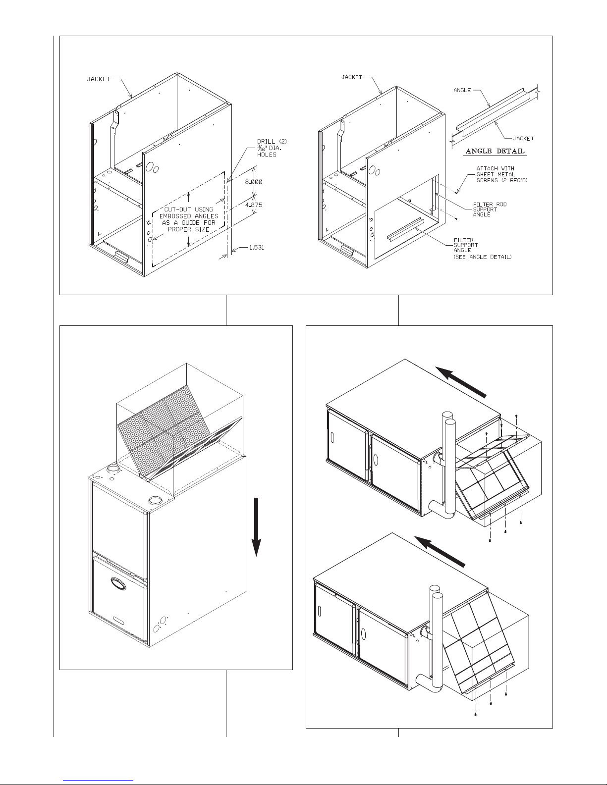
FIGURE 79
UPFLOW -- SIDE FILTER LOCATIONS
CUT-OUT AND DRILL DETAIL
FIGURE 80
DOWNFLOW -- FILTER INSTALLATION
AIRFLOW
ROD & FILTER SUPPORT ANGLE ASSEMBLY
FIGURE 81
HORIZONTAL -- FILTER INSTALLATION
AIRFLOW
AIRFLOW
I332
A087001.S01
A087101.S01
85
Page 86

!
CAUTION
DO NOT OPERATE THE SYSTEM
WITHOUT FILTERS. A PORTION
OF THE DUST ENTRAINED IN THE
AIR MAY TEMPORARILY LODGE
IN THE AIR DUCT RUNS AND AT
THE SUPPLY REGISTERS. ANY
RECIRCULATED DUST PARTICLES WILL BE HEATED AND
CHARRED BY CONTACT WITH
THE FURNACE HEAT EXCHANGER. THIS RESIDUE WILL SOIL
CEILINGS, WALLS, DRAPES,
CARPETS AND OTHER HOUSEHOLD ARTICLES.
LUBRICATION
IMPORTANT: Do Not attempt to lubri-
cate the bearings on the blower motor or
the induced draft blower motor. Addition
of lubricants can reduce the motor life
and void the warranty.
The blower motor and induced d
blower motor bearings are prelubricated
by the manufacturer and do not require
further attention.
The blower motor and induced draft
blower motor must be cleaned periodically by a qualified installer, service
agency, or the gas supplier to prevent
the possibility of overheating due to an
accumulation of dust and dirt on the
windings or on the motor exterior. The
air filters should be kept clean. As di
filters can restrict airflow. The motor
depends upon sufficient airflowing
across and through it to keep from overheating.
raft
rty
SYSTEM OPERATION
INFORMATION
Advise The Customer
IMPORTANT: Replace all blower doors
and compartment covers after servicing
the furnace. Do not operate the unit
without all panels and doors securely in
place.
1. Keep the air filters clean. The heating system will operate more effici
ently and more economically.
2. Arrange the furniture and drapes so
that the supply air registers and the
return air grilles are unobstructed.
3. Close doors and windows. This will
reduce the heating load on the system.
4. Avoid excessive use of kitchen
exhaust fans.
5. Do not permit the heat generated
by television, lamps or radios to
influence the thermostat operation.
6. Explain proper operation of the
system with constant air circulation.
ANNUAL INSPECTION
The furnace should operate for many
years without excessive scale build-up
in the flue passageways. However, it is
recommended that a qualified installer,
service agency, or the gas supplier
annually inspect the flue passageways,
the vent system and the main burners
for continued safe operation. Pay particular attention to deterioration from corrosion or o
During the annual inspection, all electrical power to the furnace should be
turned off and then restored. This will
put the furnace into a calibration cycle
on the initial call for heat. This is a five
minute (or until the heat call is satisfied)
cycle which allows the furnace to evaluate conditions It should be noted, that a
calibration cycle will occur on the initial
call for heat each t
has been interrupted to the unit.
IMPORTANT: It is recommended that at
the beginning and at approximately half
way through the heating season, a visual inspection be made of the main burner flames for the desired flame appearance by a qualified installer, service
agency or the gas supplier. If the flames
are distorted and/or there is evidence of
back pressure, check the vent and
air system for blockage. If there is car-
bon and scale in the heat exchanger
tubes, the heat exchanger assembly
should be replaced.
!
HOLES IN THE VENT PIPE OR HEAT
EXCHANGER CAN CAUSE TOXIC
FUMES TO ENTER THE HOME,
RESULTING IN CARBON MONOXIDE
POISONING OR DEATH. THE VENT
PIPE OR HEAT EXCHANGER MUST
BE REPLACED IF THEY LEAK.
ther sources.
ime after line voltage
inlet
WARNING
IMPORTANT: It is recommended that
at the beginning of the heating season, the flame sensor be cleaned with
steel wool by a qualified installer, service agency or the gas supplier.
IMPORTANT: It is recommended that
at the beginning of the heating season, the condensate trap be inspected for debris or blockage. A blocked
condensate trap can cause water to
back up into the primary heat
exchanger and lea
ping of the over temperature switches
and/or pressure switches.
IMPORTANT: It is recommended that
at the beginning of the heating sea-
son, the condensate neutralizer (if
used) be replaced by a qualified
installer, service agency or the gas
supplier.
IMPORTANT: Drain traps will often
dry out over a summer. During annual
inspection the service person must
verify that the trap still has wate
there is not enough water (or no
water) in the trap, the service person
must fill it to the appropriate level.
IMPORTANT: It is recommended that
an annual inspection and cleaning of
all furnace markings be made to
assure legibility. Attach a replacement
marking, which can be obtained
through the distributor, if any are
found to be illegible or missing.
d to nuisance trip-
r. If
REPLACEMENT PARTS
Contact your local distributor for a
complete parts list.
TROUBLESHOOTING
Figure 82 is a troubleshooting flowcharts for the sequence of operation.
Table 21 is for fault-code descriptions.
WIRING DIAGRAM
Figures 83 and 84 are complete
wiring diagrams for the furnace and
power sources.
86
Page 87

FIGURE 82
TROUBLESHOOTING CHART
MODULATING INTEGRATED
FURNACE CONTROL (IFC)
TROUBLESHOOTING GUIDE
1) Set DIP switches SW2-2 to “OFF” and SW2-3 to
“ON” for test mode - high fire.
2) Set FAN switch to “AUTO” on T-stat.
3) Set thermostat to call for heat (set temp.
differential to greater than 10°F).
4) “H” should be displayed at “SSD’s” and should
Be on steady, if flashing check dip switches
(Item “1”).
Dual SSD’S “ON”
Is thermostat heat call present?
For 24 VAC (Non-Comm. T-stat., is 24 VAC on W1 and/or W2 of
IFC. H or h should be displayed at SSD’S.
ECM = Constant CFM Blowers. (Electronically commutated motor)
TSTAT = Thermostat.
IDM = Induced Draft Motor (or Inducer).
IFC = Integrated Furnace Control (or control board).
PS = Pressure Switch(es).
PFC = Power Factor Correction Choke.
SE = Spark Electrode (s).
SSD = Seven Segment Display of Furnace control
COMM. = Communication.
I&O = Instal
lation & Operation Instructions Manual.
For Comm. System
For Non-Comm. Systems.
“A capital
is displayed at IFC SSD’S”
Capital “H”
Lower case “h”
Is a modulating
T-stat connected?
2 Stg. or 1 Stg. Non Comm. T-stat
(pre-purge) IDM runs for 30 sec. at high speed?
Spark Electrodes (SE) Energize?
Does ECM blower start on high heat
speed 15-20 seconds after burners light?
Is a fault code displayed at IFC?
(After 10 Sec. a fault code will display anyway)
-Check line voltage at I.D.M.
-Check Wires And connections between I.D.M. and I.F.C.
-Ensure line voltage between J2, Pin 1 & J2, Pin 4 of I.F.C. (High IN Output).
-Check I.D.M. Capacitor.
Check t-stat, replace if
necessary.
Check “V” signal wires &
connections, replace or
repair as necessary
Does IDM Run for 60 Sec. and then off
PROBLEM
PERSISTS
G0 T0
I
- Check all connections between I.F.C. & E.C.M. Motor.
- Check 24v to E.C.M. control (4pin connector, pin 1-4)
- Check Dip switch setting.
- Check P.F.C. choke.
- Check all wiring and connections to P.F.C choke.
- Check fault code display, see
- Check line voltage to motor (115VAC).
Note: IFC SSD’s will display “22, 33 or 23”.
H or h only
For 1st 10 Sec. only
for five minutes with fault
45, 48 or 57 displayed?
See I&O.
Does gas valve remain
energized?
“fault codes” in I & O.
Under ”Troubleshooting”
If good flame is not sensed a fault code
“11” or “13” will be displayed at SSD’s
“12” is low flame sense, furnace should
still operate well.
FAULT
in I & O Manual
- See FAULT CODES under “Troubleshooting” in
I&O Manual.
J16-4
If IFC goes into lockout (”r” will be displayed at SSD’s), shut off
main power to unit, wait 30 seconds then reset power or removed heat
call and re-establish.
?
J16-5 on IFC.
Fault code
“45”, “46” or
“57” displayed
at SSD’s.
- ensure no restrictions, such as dirty filter, blower wheel,
dampers or closed registers, Etc. exist.
- ensure good wire and connections between I.F.C. and all limits.
makes sure limits are not open when circulating air temperature is within a
specific range.
- Ensure rollouts or overtemperature limits do not need to be
reset. make sure no flame rollout in burner compartment due to blocked flue
or heat exchanger or combustion restriction.
- ensure furnace is not overfired (temp rise is above stated
range). Check gas valve, proper orifice size, gas presure
Remove heat call by setting T-stat set point below
room temperature. remove power to furnace and open
blower door. Set dip switch SW2-2 to “ON” and SW2-3
to “OFF”. Replace furnace door, reset po
furnace. Initiate new heat call. Allow heat call to
proceed through blower on delay. The burners drop
from high fire to low (40%) rate and I.B.M. energizes at
low heat CFM.
wer to
-Grounding on I.F.C. in place and continuity between screw and field
-installed ground.
-Flame sense rod clean (clean if nessessary).
-Wire continunity between flame sense rod and J1, Pin1 on I.F.C.
-Flame carries across all burners, and all burners stay lit.
- Check test mode dip switches.
- Make sure test mode has not
expired (1 hour limit).
- Fault codes at IFC SSD - see FAULT CODES under troubleshooting
in I&O manual.
- 24V Between IFC pins J16, Pin 4 & J16, Pin 5 of I.F.C.
- Make sure heat call present at T-stat.
- T-stat wires and connections
87
Page 88

SSD = Seven Segment Display of Furnace control
COMM. = Communication.
I&O = Instal
lation & Operation Instructions Manual.
3) Set thermostat to call for heat (set temp.
differential to greater than 10°F).
4) “H” should be displayed at “SSD’s” and should
Be on steady, if flashing check dip switches
(Item “1”).
For Non-Comm. Systems.
“A capital
is displayed at IFC SSD’S”
Dual SSD’S “ON”
Is thermostat heat call present?
For 24 VAC (Non-Comm. T-stat., is 24 VAC on W1 and/or W2 of
IFC. H or h should be displayed at SSD’S.
Is a fault code displayed at IFC?
(After 10 Sec. a fault code will display anyway)
H or h only
For 1st 10 Sec. only
FAULT
Under ”Troubleshooting”
in I & O Manual
Is a modulating
T-stat connected?
Check “V” signal wires &
connections, replace or
repair as necessary
Check t-
stat, replace if
necessary.
(pre-purge) IDM runs for 30 sec. at high speed?
Does IDM Run for 60 Sec. and then off
for five minutes with fault
45, 48 or 57 displayed?
- See FAULT CODES under “Troubleshooting” in
I&O Manual.
J16-4
J16-5 on IFC.
If IFC goes into lockout (”r” will be displayed at SSD’s), shut off
main power to unit, wait 30 seconds then reset power or removed heat
call and re-establish.
- Check all connections between I.F.C. & E.C.M. Motor.
- Check 24v to E.C.M. control (4pin connector, pin 1-4)
- Check Dip switch setting.
- Check P.F.C. choke.
- Check all wiring and connections to P.F.C choke.
- Check fault code display, see
“fault codes” in I & O.
- Check line voltage to motor (115VAC).
Does ECM blower start on high heat
speed 15-20 seconds after burners light?
Note: IFC SSD’s will display “22, 33 or 23”.
?
If good flame is not sensed a fault code
“11” or “13” will be displayed at SSD’s
“12” is low flame sense, furnace should
still operate well.
Fault code
“45”, “46” or
“57” displayed
at SSD’s.
- Check test mode dip switches.
- Make sure test mode has not
expired (1 hour limit).
- Fault codes at IFC SSD - see FAULT CODES under troubleshooting
in I&O manual.
- 24V Between IFC pins J16, Pin 4 & J16, Pin 5 of I.F.C.
- Make sure heat call present at T-stat.
- T-stat wires and connections
Remove heat call by setting T-stat set point below
room temperature. remove power to furnace and open
blower door. Set dip switch SW2-2 to “ON” and SW2-3
to “OFF”. Replace furnace door, reset po
wer to
furnace. Initiate new heat call. Allow heat call to
proceed through blower on delay. The burners drop
from high fire to low (40%) rate and I.B.M. energizes at
low heat CFM.
For Comm. System
Lower case “h”
Capital “H”
2 Stg. or 1 Stg. Non Comm. T-stat
-Check line voltage at I.D.M.
-Check Wires And connections between I.D.M. and I.F.C.
-Ensure line voltage between J2, Pin 1 & J2, Pin 4 of I.F.C. (High IN Output).
-Check I.D.M. Capacitor.
Spark Electrodes (SE) Energize?
See I&O.
Does gas valve remain
energized?
PROBLEM
PERSISTS
- ensure no restrictions, such as dirty filter, blower wheel,
dampers or closed registers, Etc. exist.
- ensure good wire and connections between I.F.C. and all limits.
makes sure limits are not open when circulating air temperature is within a
specific range.
- Ensure rollouts or overtemperature limits do not need to be
reset. make sure no flame rollout in burner compartment due to blocked flue
or heat exchanger or combustion restriction.
- ensure furnace is not overfired (temp rise is above stated
range). Check gas valve, proper orifice size, gas presure
-Grounding on I.F.C. in place and continuity between screw and field
-installed ground.
-Flame sense rod clean (clean if nessessary).
-Wire continunity between flame sense rod and J1, Pin1 on I.F.C.
-Flame carries across all burners, and all burners stay lit.
G0 T0
I
FIGURE 82
TROUBLESHOOTING CHART – CONTINUED
After Blower on delay, Does IDM switch to low speed
and remain a
t low speed after switching?
Does I. B. M. energize at low speed?
Does furnace continue to operate at low
fire until T-stat satisfied or heat call
removed?
Remove heat call by setting
T-stat below room temp.
Does IDM Shut off after Twenty Second post purge?
Does I. B. M. shut off after 90 seconds? (plus slew)
Remove power to furnace, open blower compartment
and restore dip switches to original settings. Replace
blower door. Restore power to unit.
Check to make sure test mode dip switches are properly set.
Ensure T-stat not
switching to high fire or
test mode dips witches
not timing out (1 hour
limit)
Double check - is heat call
completely off at IFC?
troubelshooting in the I & O Manual
Fault code displayed?
See FAULT CODES under
- Check wire and all connections between I.F.C.J2 and I.D.M
- Check for 115 VAC on P2.
- Check I.D.M. capacitor.
- Check I.D.M. low speed. Replace if neccessary.
C
- Check all connections between IFC and ECM motor.
- Check 24V to ECM Motor. (low voltage connector, pins 1 & 4)
- Check P.F.C. Choke.
- Check all wiring and connections to P.F.C. choke.
- Check fault code display and see “fault codes” In I & O.
** System will attempt to light 4 times. Voltage Is present at gas valve for
only 7 seconds during each ignition trial. System will enter a 1 hour
lockout after 4 attempts.
92-22744-23-00
88
Page 89

TABLE 20
y
NORMAL OPERATION CODES
y
p
NORMAL OPERATION CODES
Ke
CODE
DISPLAYED TEXT
CODE AT DUAL 7-SEGMENT DISPLAY OF IFC
DESCRIPTION
NORMAL OPERATION CODES
CODE AT DUAL 7-SEGMENT DISPLAY OF IFC: 0
0
DESCRIPTION: This code is displayed anytime there is no fault code to display and no thermostat call present. The
furnace is idle.
CODE AT DUAL 7-SEGMENT DISPLAY OF IFC
DESCRIPTION: This code is displayed any time there is a call for gas heat. The lower-case "h" is displayed when the
H or h
(steady)
C
HP
dF
furnace is calibrating. Calibration will occur during the first heat call after power reset or power-up. The calibration cycle
allows the blower to be adjusted to deliver the proper airflow amount for a given heat rise at a given rate. Calibration
takes more five minutes at a reduced input. Calibration will not occur if the SA sensor is not connected. If either (upper
case "H" or lower-case "h" is blinking, it is an indication that a "V" signal is not present on a system that is noncommunicating. Blinking of this code will not be considered a fault if the thermostat chosen for use is noncommunicating and non-modulating. See fault codes "H" (blinking) and "h" (blinking) for more information.
CODE AT DUAL 7-SEGMENT DISPLAY OF IFC
DESCRIPTION: This code indicates the furnade is in cooling mode (any stage).
CODE AT DUAL 7-SEGMENT DISPLAY OF IFC
DESCRIPTION: This code indicates the furnade is in heat-pump heating mode (dual-fuel systems only) (any stage).
F
CODE AT DUAL 7-SEGMENT DISPLAY OF IFC
DESCRIPTION: The furnace is in continous fan mode.
CODE AT DUAL 7-SEGMENT DISPLAY OF IFC: dF
DESCRIPTION: This code indicates that the heat-pump is in deFrost mode (dual-fuel systems only) and furnace is
erating as supplemental heat at a fixed 65% of maximum gas heating capacity.
o
STANDBY MODE
GAS HEAT MODE
: H or h (steady on - not blinking)
COOLING MODE
: C
HEAT PUMP HEAT MODE
: HP or hP
FAN MODE
: F
DEFROST MODE
Cd
DEHUMIDIFICATION MODE
CODE AT DUAL 7-SEGMENT DISPLAY OF IFC: Cd
DESCRIPTION
dehumidification is active, the cooling airflow will be reduced in order to allow water to accumulate on the condenser
thereb
: This code indicates that cooling is active with dehumidification active at the same time. When
removing humidity from the conditioned environment.
89
Page 90

TABLE 21
Ke
y
FAULT CODES
FAULT CODES
DISPLAYED TEXT
DESCRIPTION
DESCRIPTION: This message will not be displayed at the furnace. It will be displayed at the condenser but it involves
the furnace. It is an indicator that the maximum airflow that can be supplied by the furnace is not enough capacity for
the condenser.
CAUSE
: The condenser selected is too large for the airflow capacity of the furnace.
FAULT
CODE
NO SHARED DATA
DESCRIPTION: This code is displayed anytime there is no shared data at the furnace or (for communicating systems
only) on the network (e.g. at the condenser or thermostat). The shared data is electronically stored data that is used to
define (among other things) blower operation. Without the shared data, the furnace can not function. Note that shared
data may be available even if there is no card attached to the furnace control. A missing memory card will display fault
code "d4" if shared data is available on the network.
STATUS
: This is a critical fault. The air conditioner (or heat pump) condenser will not operate in communicating
mode.
SOLUTION
SOLUTION: Replace the missing memory card into the connector labeled J15 on the furnace control (I.F.C.). If the
original card can not be found, a replacement card can be ordered from ProStock. Be sure to order the correct
memory card for the furnace. Note: Furnace power must be cycled off and then on again after replacing the card or
the shared data will not be read.
d1
MESSAGES TO HOMEOWNER AT COMM. THERMOSTAT: "CALL FOR SERVICE " & "CHECK FURNACE".
d3
CAUSE
STATUS
MESSAGE IN FAULT AREA OF COMMUNICATING THERMOSTATS: AIRFLOW MISMATCH
SOLUTION
: The condenser or furnace should be replaced with a condenser or furnace which will match the
necessary airflow requirements of the condenser. Check specification sheets for both the furnace and the condenser
to determine airflow capacity needed and supplied.
MESSAGE IN FAULT AREA OF COMM. THERMOSTAT
: "NO SHARED DATA "
CODE AT DUAL 7-SEGMENT DISPLAY OF IFC & FAULT AREA OF COMM. THERMOSTAT
: d1
CODE AT DUAL 7-SEG DISPLAY OF HP/AC & FAULT AREA OF COMM. THERMOSTAT
: d3
MESSAGES TO HOMEOWNER AT COMMUNICATING THERMOSTATS
: "CALL FOR SERVICE " & "CHECK
FURNACE".
CAUSE
: Typically, the memory card will be missing from the furnace. In most cases, the cause of this fault will be the
loss or disconnection of the original memory card from the furnace control (or I.F.C.). When the furnace control (or
I.F.C.) is replaced, the memory card must be broken away, saved and installed in the replacement control. This is
explained in detail in the section of this book titled REPLACING THE FURNACE CONTROL.
STATUS
: This is a critical fault. The furnace will not operate in any mode.
AIRFLOW MISMATCH
EXPECTED OPERATION: No operation (including thermostat) will be permitted without the shared data. The shared
data defines the IBM (Indoor Blower Motor) speed-torque curve. Without this information, the IBM can not operate.
Refer to the section of this manual titled "INTEGRATED FURNACE CONTROL" under the subsection titled "MEMORY
CARD" for details on the hierarchy of use of multiple copies of shared data and distribution (among other details) of
shared data.
EXPECTED OPERATION
: No cooling or heat-pump heating operation can take place. However, all other modes of
operation (including gas heat) should proceed as normal. Refer to the section of this manual titled "INTEGRATED
FURNACE CONTROL" under the subsection titled "MEMORY CARD" for details on the hierarchy of use of multiple
copies of shared data and distribution (among other details) of shared data.
CODE AT DUAL 7-SEGMENT DISPLAY OF IFC & FAULT AREA OF COMM. THERMOSTAT
MESSAGES TO HOMEOWNER AT COMM. THERMOSTAT
EXPECTED OPERATION
MESSAGE IN FAULT AREA OF COMM. THERMOSTAT
FURNACE FAULT CODES EXPANDED W/DESCRIPTIONS AND SOLUTIONS
90
Page 91

TABLE 21
FURNACE FAULT CODES EXPANDED W/DESCRIPTIONS AND SOLUTIONS – CONTINUED
FAULT CODES
NOTE: The text in the “DISPLAYED TEXT” box shows combinations of upper-case and lower-case letters. Upper-case letters are used
in the message displayed at the thermostat active fault screen. For example, the text CARD-HARDware CoNFLiCT indicates that the
message displayed at the thermostat active fault screen will be CARD-HARD CNFLCT.
NOTE: The following fault codes will not be stored back-to-back in the fault buffer. These will only be stored in the buffer if the previous
fault stored was a different fault. 82, 11, 45, 46 & 57.
91
Page 92

TABLE 21
FURNACE FAULT CODES EXPANDED W/DESCRIPTIONS AND SOLUTIONS – CONTINUED
92
Page 93

TABLE 21
FURNACE FAULT CODES EXPANDED W/DESCRIPTIONS AND SOLUTIONS – CONTINUED
93
Page 94

TABLE 21
FURNACE FAULT CODES EXPANDED W/DESCRIPTIONS AND SOLUTIONS – CONTINUED
94
Page 95

TABLE 21
FURNACE FAULT CODES EXPANDED W/DESCRIPTIONS AND SOLUTIONS – CONTINUED
95
Page 96

TABLE 21
FURNACE FAULT CODES EXPANDED W/DESCRIPTIONS AND SOLUTIONS – CONTINUED
96
Page 97

TABLE 21
FURNACE FAULT CODES EXPANDED W/DESCRIPTIONS AND SOLUTIONS – CONTINUED
97
Page 98

TABLE 21
FURNACE FAULT CODES EXPANDED W/DESCRIPTIONS AND SOLUTIONS – CONTINUED
98
Page 99

TABLE 21
FURNACE FAULT CODES EXPANDED W/DESCRIPTIONS AND SOLUTIONS – CONTINUED
99
Page 100

TABLE 21
FURNACE FAULT CODES EXPANDED W/DESCRIPTIONS AND SOLUTIONS – CONTINUED
when the inducer is energized at high speed.
100
 Loading...