

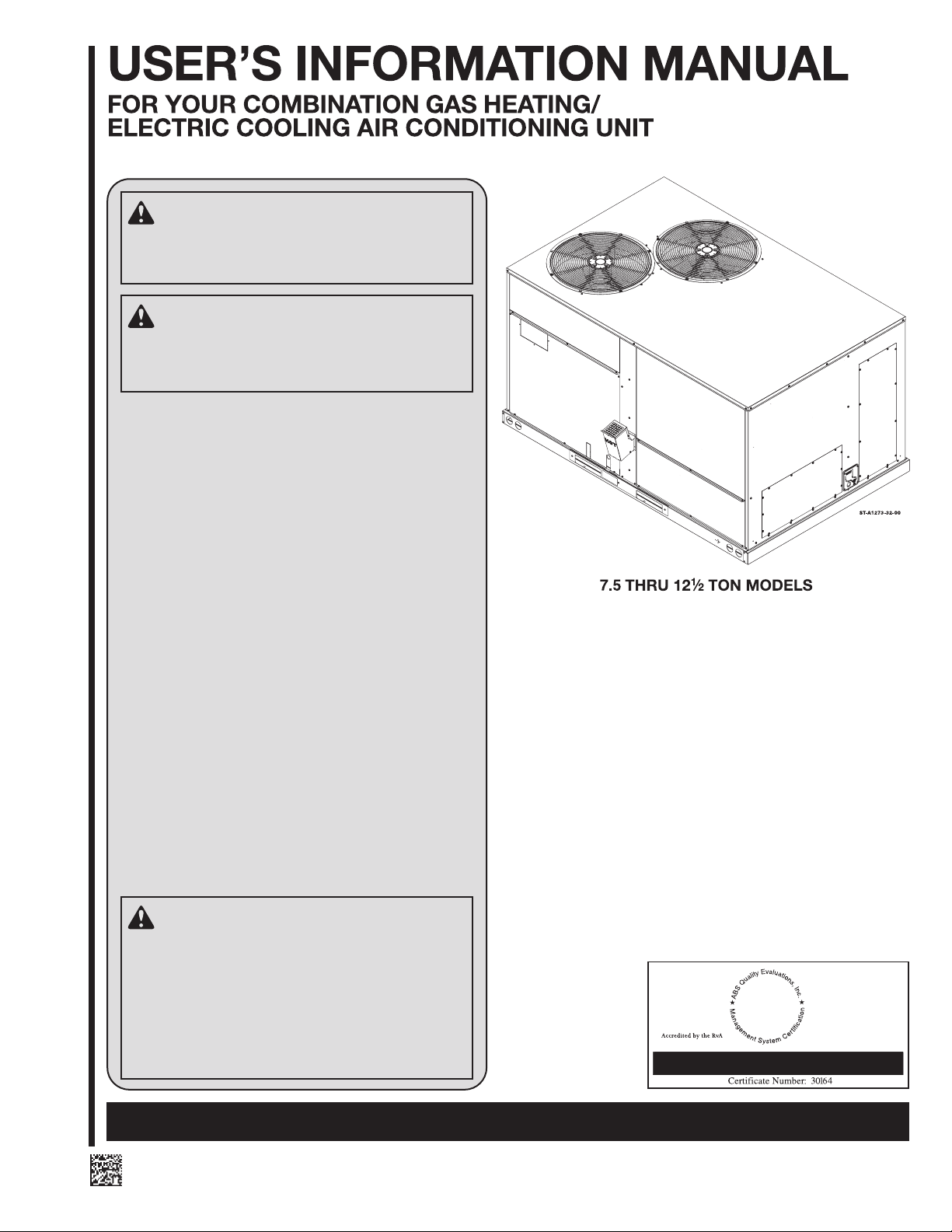
Page 1
WARNING
If the information in this manual is not followed exactly, a fire or explosion may result, causing property damage, personal injury or loss of life.
WARNING
FIRE OR EXPLOSION HAZARD
Failure to follow safety warnings exactly could result
in serious injury, death or property damage.
— Do not store or use gasoline or other flammable
vapors and liquids, or other combustible materials in
the vicinity of this or any other appliance.
— WHAT TO DO IF YOU SMELL GAS
• Do not try to light any appliance.
• Do not touch any electrical switch; do not use any
phone in your
• Immediately call your gas supplier from a neighbor’s phone. Follow the gas supplier’s instructions.
• If you cannot reach your gas supplier, call the fire
department.
• Do not return to your home until authorized by the
gas supplier or fire department.
— DO NOT RELY ON SMELL ALONE TO DETECT LEAKS.
DUE TO VARIOUS FACTORS, YOU MAY NOT BE ABLE
TO SMELL FUEL GASES.
• U.L. and/or C.S.A. recogniz
bon monoxide) detectors are recommended in all
applications, and their installation should be in accordance with the manufacturer’s recommendations and/or local laws, rules, regulations, or
customs.
— Improper installation, adjustment, alteration, service
or maintenance can cause injury, property damage or
death. Refer to this manual. Installation and service
must be performed b
agency or the gas supplier. In the commonwealth of
Massachusetts, installation must be performed by a licensed plumber or gas filter for appropriate fuel.
building.
ed fuel gas and CO (car-
y a qualified installer, service
WARNING
PROPOSITION 65: THIS FURNACE CONTAINS
FIBERGLASS INSULATION. RESPIRABLE PARTICLES OF FIBERGLASS ARE KNOWN TO THE
STATE OF CALIFORNIA TO CAUSE CANCER. EXHAUST GAS FROM THIS FURNACE CONTAINS
CHEMICALS, INCLUDING CARBON MONOXIDE,
KNOWN TO THE STATE OF CALIFOR NIA TO
CAUSE BIRTH DEFECTS OR OTHER REPRODUCTIVE HARM.
DO NOT DESTROY. PLEASE READ CAREFULLY AND KEEP IN A SAFE PLACE FOR FUTURE REFERENCE.
SUPERSEDES 92-106167-01-00
ISO 9001:2015
92-106167-01-01
Page 2
IMPROPER INSTALLA TION, ADJUSTMENT, ALTERATION, SERVICE OR
MAINTENANCE CAN CAUSE PROPERTY DAMAGE, PERSONAL INJURY
OR DEATH. FOR ASSISTANCE OR
ADDITIONAL INFORMATION CONSULT A QUALIFIED INSTALLER,
SERVICE AGENCY OR THE GAS
SUPPLIER.
Should the gas supply fail to shut
8.
off or if overheating occurs, shut
off the gas valve to the furnace
before shutting off the electrical
supply.
DUCT LEAKS CAN CREATE AN UNBALANCED SYSTEM AND DRAW POLLUTANTS SUCH AS DIRT, DUST, FUMES
AND ODORS INTO THE HOME CAUSING
PROPERTY DAMAGE. FUMES AND
ODORS FROM TOXIC, VOLATILE OR
FLAMMABLE CHEMICALS, AS WELL AS
AUTOMOBILE EXHAUST AND CARBON
MONOXIDE (CO), CAN BE DRAWN INTO
THE LIVING SPACE THROUGH LEAKING
DUCTS AND UNBALANCED DUCT
SYSTEMS CAUSING PERSONAL INJURY
OR DEATH.
IF AIR-MOVING EQUIPMENT OR
DUCTWORK IS LOCATED IN SPACES
CONTAINING FUEL BURNING APPLIANCES SUCH AS WATER HEATERS OR
BOILERS, ALL JOINTS, SEAMS, AND
OPENINGS IN THE EQUIPMENT AND
DUCT MUST ALSO BE SEALED TO
PREVENT DEPRESSURIZATION OF THE
SPACE AND POSSIBLE MIGRATION OF
COMBUSTION BYPRODUCTS INCLUDING CARBON MONOXIDE INTO THE
LIVING SPACE.
Page 3
NOTICE
IMPROPER INSTALLATION, OR
INSTALLATION NOT MADE IN ACCORDANCE WITH THE CSA INTERNATIONAL (CSA) CERTIFICATION OR THESE
INSTRUCTIONS, CAN RESULT IN
UNSATISFACTORY OPERATION
AND/OR DANGEROUS CONDITIONS
AND ARE NOT COVERED BY THE
UNIT WARRANTY.
IMPORTANT INFORMATION
ABOUT EFFICIENCY AND
INDOOR AIR QUALITY
Central cooling and heating equipment is
only as efficient as the duct system that
carries the cooled or heated air. To
maintain efficiency, comfort and good
indoor air quality, it is important to have
the proper balance between the air
being supplied to each room and the air
returning to the cooling and heating
equipment.
Proper balance and sealing of the duct
system improves the efficiency of the
heating and air conditioning system and
improves the indoor air quality of the
occupied space by reducing the amount
of airborne pollutants that enter
occuplied spaces from spaces where the
ductwork and / or equipment is located.
The manufacturer and the U.S. Environ-
mental Protection Agency’s Energy Star
Program recommend that central duct
systems be checked by a qualified
contractor for proper balance and
sealing.
NOTE: The time delays vary depending
on how the wires are connected.
a preselected time of
a preselected time.
a preselected time to extract
CARBON MONOXIDE (CO) IS A COLORLESS, ODORLESS, POISONOUS GAS
THAT CAN CAUSE SEVERE PERSONAL
INJURY OR DEATH. CARBON MONOXIDE CAN BE PRODUCED BY ANY
FUEL-BURNING DEVICE.
CARBON MONOXIDE FROM ANY FUEL
BURNING DEVICES CAN BE INADVERTENTLY DRAWN INTO AND DISTRIBUTED THROUGH THE LIVING SPACE BY
THE NORMAL OPERATION OF THE
CENTRAL HEATING / AIR CONDITIONING SYSTEM.
APPLIANCES AND FUEL BURNING
DEVICES MUST BE INSTALLED, OPERATED AND MAINT AINED IN ACCOR-
DANCE WITH THE MANUFACTURER’S
INSTRUCTIONS.
EVEN WITH DOORS AND WINDOWS OR
VENTS OPEN, CARBON MONOXIDE
CAN BUILD UP AND SEEP INTO THE
LIVING SPACE THROUGH CRACKS
AND OPENINGS IN THE STRUCTURE.
TOXIC FUMES, INCLUDING CARBON
MONOXIDE, CAN ALSO BE DRAWN
INTO THE LIVING SPACE THROUGH
OPENINGS AND SEAMS IN THE
CENTRAL HEATING AND AIR CONDITIONING EQUIPMENT AND / OR
DUCTWORK.
FOR THESE REASONS, THE U.S.
CONSUMER PRODUCT SAFETY COMMISSION (CPSC) RECOMMENDS THAT
EVERY HOME HAVE AT LEAST ONE
CARBON MONOXIDE ALARM
INSTALLED IN THE HALLWAY NEAR
THE BEDROOMS IN EACH SEPARATE
SLEEPING AREA OF THE HOME.
CARBON MONOXIDE ALARMS SHOULD
BE CERTIFIED TO THE REQUIREMENTS
OF THE MOST RECENT UL, IAS OR CSA
STANDARD, AND SHOULD BE
INSTALLED, OPERATED AND MAINTAINED IN ACCORDANCE WITH THE
ALARM MANUFACTURER’S INSTRUCTIONS.
Page 4

WHITE RODGERS 36H54-473
TWO STAGE GAS VALVE
Used on (-)GED Models with Fuel Code: 3A, 3B, 3C
Use only your hand to move the gas
control switch. Never use tools. If the
switch will not move by hand, don’t
try to repair it; call a qualified service
technician. Force or attempted repair
may result in a fire or explosion.
HONEYWELL VR8305Q
TWO STAGE GAS VALVE
ST-A1273-36-00
Used on (-)GED Models with Fuel Code: 3D, 3E, 3F
Page 5

NORMAL FURNACE
OPERATING SEQUENCE
This unit is equipped with a two stage
integrated direct spark ignition control.
NORMAL HEAT MODE
A. Call For First Stage (low fire) Only:
1. Zone thermostat contacts close, a call
for first stage (low fire) heat is initiated.
2. Control runs self check.
3. Control checks the high-limit switch
for normally closed contacts, the
pressure switch for normally open
contacts, and all flame rollout
switches for continuity.
4. Control energizes the inducer.
5. Control checks the low-fire pressure
switch for closure.
6. If the pressure switch is closed, the
control starts a 30 second prepurge.
If the pressure switch is still open
after 180 seconds, the inducer will be
energized until closure.
7. After prepurge timeout, control
initiates spark for 2 seconds
minimum, 7 second maximum ignition
trial, initiates 45 second, second
stage (high fire) warm up timing.
8. Control detects flame, de-energizes
spark and initiates 45 s econd delay
on blower timing.
9. After a fixed 45 s econds indoor
blower delay on, t
the indoor blower.
10. After the 45 second s econd stage
warmup period control checks
thermostat input. If only W1 is called
for, W2 is de-energized.
11. Control enters normal operating loop
where all inputs are continuously
checked.
B. Call For Second Stage, After First
Stage Established; Starting from A.11:
1. If a call for second stage (high fire) is
initiated after a call f or f irst stage heat
is established, the control assures the
pressure switch is closed and
energizes the second stage of the
gas valve.
2. Control enters normal operating loop
where all inputs are continuously
checked.
C. Second Stage Satisfied; First Stage
Still Called For; Starting From B.2:
1. Once the call for second stage is
satisfied, the control reduces the gas
valve to first stage.
2. Control enters normal operating loop
where all inputs are continuously
checked.
D. First Stage Satisfied:
1. Zone thermostat is satisfied.
2. Control de-energizes gas valve.
3. Control senses loss of flame.
4. Control initiates 5 second inducer
postpurge and 90 second indoor
blower delay off.
5. Control de-energizes inducer blower.
6. Control de-energizes indoor blower.
7. Control in the stand by mode with
solid red LED.
he control energizes
E. First Stage and Second Stage Called
Simultaneously:
1. Zone thermostat contacts close, a call
for first stage (low fire) and second
stage (high fire) heat is initiated.
2. Control runs self check.
3. Control checks the limit switch for
normally closed contacts, the switch
for normally open contacts, and t he
flame rollout switch for continuity.
4. Control energizes the inducer.
5. Control checks the pressure switch for
closure.
6. If the pressure switch is closed, the
control starts a 30 second prepurge. If
the switch is still open after 180
seconds, the inducer will be energized
until closure.
7. After prepurge timeout, control
initiates spark for 2 seconds minimum,
7 second maximum ignition trial, and
initiates 45 second s econd stage
warm up timing.
8. Control detects flame, de-energizes
spark and starts a 45 second indoor
blower delay on timing.
9. After a fixed 45 s econds indoor blower
delay on
indoor blower.
10. After the 45 seconds second stage
warmup period control checks the
thermostat input. If W1 and W2 is
present control enters normal
operating loop where all inputs are
continuously checked.
F. First Stage and Second Stage
Removed Simultaneously:
1. Upon a loss of W1 and W2 the gas
valve is de-energized.
2. Upon a loss of flame, the inducer will
complete a 5 s econd postpurge and
the indoor blower will complete a 90
second delay off.
3. Control in the stand by mode with
solid red LED.
The integrated control is a four-ignition
system.
After a total of four cycles without sensing
main burner flame, the system goes into a
100% lockout mode. After one hour, the
ignition control repeats the prepurge and
ignition cycles for 4 tries and then go into
100% lockout mode again. It continues
this sequence of cycles and lockout each
hour until ignition is successful or power is
interrupted. During the lockout mode,
neither the ignitor or gas valve will be
energized until the system is reset by
turning the thermostat to the “OFF”
position or interrupting t he electrical power
to the
induced draft blower and main burner will
shut off when t he t hermostat is satisfied.
The circulating air blower will start and run
on the heating speed if the thermostat fan
switch is in the “ON” position.
, the control energizes the
unit for 3 seconds or longer. The
All integrated furnace c ontrols come
standard with a 7 s egment diagnostic
display. During standby mode with no f ault
codes present, the display will read “0”
(zero). During normal thermostat heating,
cooling or continuous fan operations a letter
will be displayed to describe t he mode of
operation outlined in the “Installation and
Operating Manual” normal operation codes.
OPERATING INSTRUCTIONS
This appliance is equipped with integrated
furnace control. This device lights the main
burners each time the room thermostat
(closes) calls for heat. See operating
instructions on the back of the
furnace/controls access panel.
!
WARNING
DO NOT ATTEMPT TO MANUALLY
LIGHT THIS FURNACE WITH A MATCH
OR ANY OPEN FLAME. ATTEMPTING
TO DO SO CAN CAUSE AN EXPLOSION
OR FIRE RESULTING IN PROPERTY
DAMAGE, PERSONAL INJURY OR
DEATH.
TO START THE FURNACE
1. Set the thermostat to its lowest setting.
2. Turn off all electric power to the
applianc
3. This appliance does not have a pilot. It
is equipped with an ignition device
which automatically lights the burner.
Do not
4. Remove control door.
5. Move control switch/knob on the gas
valve to the “OFF” position.
6. Wait five (5) minutes to clear out any
gas. Then smell for gas, including
near the floor. If you smell gas, STOP!
Follow B in the safety information on
the Operating Instructions located on
the back of the controls/access panel.
If you don’t smell gas, go to the next
step.
7. Move the gas control switch/knob on
the gas valve from “OFF” position to
“ON” position. Operate this appliance
with the gas control switch/knob on the
gas valve in the “ON” position only.
8. Replace the control door.
9. Turn on all electric power to the
appliance.
10. Set the thermostat to the desired
setting.
11. If the appliance will not operate, follow
the instructions below on how to shut
down the furnace.
e.
try to light the burner by hand.
5
Page 6

!
WARNING
THE SPARK IGNITOR AND IGNITION
LEAD FROM THE IGNITION
CONTROL ARE HIGH VOLTAGE.
KEEP HANDS OR TOOLS AWAY TO
PREVENT ELECTRICAL SHOCK.
SHUT OFF ELECTRICAL POWER
BEFORE SERVICING ANY OF THE
CONTROLS. FAILURE TO ADHERE
TO THIS WARNING CAN RESULT IN
PERSONAL INJURY OR DEATH.
The initial start-up on a new installation
may require the control system to be
energized for some time until air has
bled through the system and fuel gas is
available at the burners.
TO SHUT DOWN FURNACE
1. Set the thermostat to the lowest
setting.
2. Turn off all electric power to the
appliance if service is to be
performed.
3. Remove control door.
4. Move control switch/knob on the
gas valve to the “OFF” position.
5. Replace control door.
!
WARNING
SHOULD OVERHEATING OCCUR OR
THE GAS SUPPLY FAIL TO SHUT OFF,
SHUT OFF THE MANUAL GAS VALVE
TO THE APPLIANCE BEFORE
SHUTTING OFF THE ELECTRICAL
SUPPLY. FAILURE TO DO SO CAN
RESULT IN AN EXPLOSION OR FIRE
CAUSING PROPERTY DAMAGE,
SEVERE PERSONAL INJURY OR
DEATH!
BURNERS
Burners for these units have been
designed so that field adjustment is not
required. Burners are tray-mounted and
accessible for easy cleaning when
required.
MANUAL RESET
OVERTEMPERATURE
CONTROL
Two manual reset overtemperature
controls are located on the burner shield.
These devices senses blockage in the
heat exchanger or insufficient combustion
air. This shuts off the main burners if
excessive temperatures occur in the
burner compartment.
Operation of this control indicates an
abnormal condition. Therefore, the unit
should be examined by a qualified
installer, service agency, or the gas
supplier before being placed back into
operation.
!
WARNING
DO NOT ATTEMPT TO DEFEAT THIS
IMPORTANT SAFETY DEVICE. DO NOT
RESET THE OVERTEMPERATURE
CONTROL WITHOUT TAKING
CORRECTIVE ACTION TO ASSURE
THAT AN ADEQUATE SUPPLY OF
COMBUSTION AIR IS MAINTAINED
UNDER ALL CONDITIONS OF OPERATION
AND THAT NO HEAT EXCHANGER TUBES
ARE BLOCKE
REPLACE THIS CONTROL ONLY WITH
THE IDENTICAL REPLACEMENT PART.
FAILURE TO ADHERE TO THIS WARNING
CAN RESULT IN PERSONAL INJURY
OR DEATH.
D OR PERFORATED.
PRESSURE SWITCH
This furnace has two pressure switches for
sensing a blocked exhaust or a failed
induced draft blower. They are normally
open and close when the induced draft
blower starts, indicating air flow through t he
combustion chamber.
LIMIT CONTROL
The supply air high temperature limit cut-off
is set at the factory and cannot be adjusted.
It is calibrated to prevent the air
temperature leaving the furnace from
exceeding the maximum outlet air
temperature.
!
WARNING
DO NOT JUMPER THIS DEVICE! DOING
SO CAN CAUSE A FIRE OR EXPLOSION
RESULTING IN PROPERTY DAMAGE,
PERSONAL INJURY OR DEATH.
IMPORTANT: Replace this control only
with the identical replacement part.
6
Page 7

Page 8

CAN RESULT IN BODILY INJURY,
SEVERE ELECTRICAL SHOCK, OR
DEATH.
Filter quantity: 4
Filter size: 2” × 20” × 20”
CM 1217
 Loading...