

Rheem RGEA16 Installation Manual
INSTALLATION INSTRUCTIONS
ISO 9001:2008
Seasonal Energy Efficiency Ratio (SEER)
Annual Fuel Utilization Efficiency -
AFUE
HIGHMID
16.0
81.0%
RGEA16
THIS MODEL
10.6
—
Uses least energy
➞
16.05
78% 82% 88% 97%
PACKAGE GAS ELECTRIC
FEATURING EARTH-FRIENDLY R-410A REFRIGERANT
RGEA16 UP TO 16 SEER (2-5 TONS)
(14 SEER &
ABOVE)
U.L. recognized fuel gas and CO (carbon monoxide) detectors are recommended in all
applications, and their installation should be in accordance with the manufacturer’s
recommendations and/or local laws, rules, regulations, or customs.
92-21916-79-00

TABLE OF CONTENTS
I. Safety Information .................................................................................................3
II. Introduction............................................................................................................6
III. Checking Product Received..................................................................................6
IV. Specifications ........................................................................................................6
A. General .............................................................................................................6
B. Major Components............................................................................................6
C.R-410A Refrigerant...........................................................................................6
D.Comfort Alert System........................................................................................7
1. Comfort Alert.................................................................................................7
2. High Pressure Control...................................................................................8
3. Low Pressure Control....................................................................................8
4. Comfort Alert With Active Protection.............................................................8
V. Unit Dimensions ..................................................................................................10
VI. Installation ...........................................................................................................12
A. General ...........................................................................................................12
1. Pre-Installation Check................................................................................12
2. Location Considerations.............................................................................12
B. Outside Installation..........................................................................................12
C.Attaching Exhaust and Combustion Air Inlet Hoods .......................................13
D.Cover Panel Installation/Conversion Procedure .............................................14
1. Horizontal to Downflow ...............................................................................14
2. Downflow to Horizontal ...............................................................................14
E. Clearances......................................................................................................14
F. Rooftop Installation .........................................................................................16
G.Ductwork .........................................................................................................16
H.Return Air........................................................................................................18
I. Filters ..............................................................................................................19
VII. Gas Supply, Condensate Drain and Piping.........................................................21
A. Gas Connection ..............................................................................................21
B. LP Conversion Two Stage Gas Heat ..............................................................22
C.NOx Models ....................................................................................................22
D.Adjusting or Checking Furnace Input..............................................................23
E. Condensate Drain ...........................................................................................24
VIII. Wiring ..................................................................................................................24
A. Power Supply..................................................................................................24
B. Hook Up ..........................................................................................................25
C.Internal Wiring.................................................................................................26
D.Thermostat......................................................................................................26
IX. Furnace Section Controls and Ignition System ...................................................27
A. Normal Furnace Operating Sequence Two Stage Gas Heat..........................27
B. Operating Instructions.....................................................................................28
C.Burners............................................................................................................29
D.Manual Reset Overtemperature Control.........................................................29
E. Pressure Switch ..............................................................................................29
F. Limit Control....................................................................................................29
X. System Operating Information.............................................................................29
A. Advise the Customer.......................................................................................29
B. Furnace Section Maintenance ........................................................................30
C.Lubrication.......................................................................................................31
D.Cooling Section Maintenance .........................................................................31
E. Replacement Parts..........................................................................................32
F. Charging..........................................................................................................32
XI. Units with ECM Blower Motors (RGEA16 Models Only) .....................................33
A. ECM Motor Interface Control and Settings (RGEA16 Units Only) ..................33
B. Transformer Protection ...................................................................................34
C.Using the Onboard LED to Determine Blower CFM........................................34
D.Unit Operation with Two-Stage Cooling..........................................................35
E. Cooling Airflow Adjustments ...........................................................................35
F. Heating Airflow Adjustments...........................................................................38
G.Cooling Delay Profiles.....................................................................................38
H.Cooling Mode Dehumidification ......................................................................39
I. On Demand Dehumidification Airflow Adjustment ..........................................39
XII. General Data..................................................................................................41-44
XIII. Miscellaneous......................................................................................................45
XIV. Airflow Performance Data....................................................................................46
XV. Wiring Diagrams.............................................................................................47-48
XVI. Charge Charts................................................................................................49-56
XVII. Troubleshooting..............................................................................................57-58
XVIII. Comfort Alert Diagnostic Chart............................................................................59
2
I. SAFETY INFORMATION
WARNING
!
PROPOSITION 65: THIS FURNACE CONTAINS FIBERGLASS INSULATION.
RESPIRABLE PARTICLES OF FIBERGLASS ARE KNOWN TO THE STATE OF
CALIFORNIA TO CAUSE CANCER. EXHAUST GAS FROM THIS FURNACE
CONTAINS CHEMICALS, INCLUDING CARBON MONOXIDE, KNOWN TO THE
STATE OF CALIFORNIA TO CAUSE BIRTH DEFECTS OR OTHER REPRODUCTIVE HARM.
WARNING
!
THE MANUFACTURER’S WARRANTY DOES NOT COVER ANY DAMAGE OR
DEFECT TO THE AIR CONDITIONER CAUSED BY THE ATTACHMENT OR USE
OF ANY COMPONENTS, ACCESSORIES OR DEVICES (OTHER THAN THOSE
AUTHORIZED BY THE MANUFACTURER) INTO, ONTO OR IN CONJUNCTION
WITH THE AIR CONDITIONER. YOU SHOULD BE AWARE THAT THE USE OF
UNAUTHORIZED COMPONENTS, ACCESSORIES OR DEVICES MAY
ADVERSELY AFFECT THE OPERATION OF THE AIR CONDITIONER AND MAY
ALSO ENDANGER LIFE AND PROPERTY. THE MANUFACTURER DISCLAIMS
ANY RESPONSIBILITY FOR SUCH LOSS OR INJURY RESULTING FROM THE
USE OF SUCH UNAUTHORIZED COMPONENTS, ACCESSORIES OR DEVICES.
WARNING
!
UNITS ARE NOT DESIGN CERTIFIED TO BE INSTALLED INSIDE THE STRUCTURE. DOING SO CAN CAUSE INADEQUATE UNIT PERFORMANCE AS WELL
AS PROPERTY DAMAGE AND CARBON MONOXIDE POISONING RESULTING
IN PERSONAL INJURY OR DEATH.
WARNING
!
DISCONNECT ALL POWER TO UNIT BEFORE STARTING MAINTENANCE.
FAILURE TO DO SO CAN CAUSE ELECTRICAL SHOCK RESULTING IN PERSONAL INJURY OR DEATH.
WARNING
!
THESE UNITS ARE DESIGNED CERTIFIED FOR OUTDOOR INSTALLATION
ONLY. INSTALLATION INSIDE ANY PART OF A STRUCTURE CAN RESULT IN
INADEQUATE UNIT PERFORMANCE AS WELL AS PROPERTY DAMAGE.
INSTALLATION INSIDE CAN ALSO CAUSE RECIRCULATION OF FLUE PRODUCTS INTO THE CONDITIONED SPACE RESULTING IN PERSONAL INJURY
OR DEATH.
WARNING
!
THIS UNIT MUST NOT BE INSTALLED DIRECTLY ON WOOD FLOORING, CLASS
A, CLASS B OR CLASS C ROOF COVERING MATERIALS, OR ANY OTHER COMBUSTIBLE STRUCTURE EXCEPT AS SPECIFIED IN FIGURE 15. FAILURE TO
ADHERE TO THIS WARNING CAN CAUSE A FIRE OR EXPLOSION RESULTING
IN PROPERTY DAMAGE, PERSONAL INJURY OR DEATH.
WARNING
!
DO NOT, UNDER ANY CIRCUMSTANCES, CONNECT RETURN DUCTWORK TO
ANY OTHER HEAT PRODUCING DEVICE SUCH AS FIREPLACE INSERT,
STOVE, ETC. UNAUTHORIZED USE OF SUCH DEVICES MAY RESULT IN FIRE,
CARBON MONOXIDE POISONING, EXPLOSION, PERSONAL INJURY, OR
PROPERTY DAMAGE.
3
WARNING
!
NEVER ALLOW PRODUCTS OF COMBUSTION OR THE FLUE PRODUCTS TO
ENTER THE RETURN AIR DUCTWORK, OR THE CIRCULATING AIR SUPPLY.
ALL RETURN DUCTWORK MUST BE ADEQUATELY SEALED AND SECURED
TO THE FURNACE WITH SHEET METAL SCREWS, AND JOINTS TAPED. ALL
OTHER DUCT JOINTS MUST BE SECURED WITH APPROVED CONNECTIONS
AND SEALED AIRTIGHT.
FAILURE TO PREVENT PRODUCTS OF COMBUSTION FROM BEING CIRCULATED INTO THE LIVING SPACE CAN CREATE POTENTIALLY HAZARDOUS
CONDITIONS, INCLUDING CAROBON MONOXIDE POISONING THAT COULD
RESULT IN PERSONAL INJURY OR DEATH.
WARNING
!
DO NOT USE AN OPEN FLAME TO CHECK FOR LEAKS. THE USE OF AN OPEN
FLAME CAN RESULT IN FIRE, EXPLOSION, PROPERTY DAMAGE, PERSONAL
INJURY OR DEATH.
WARNING
!
THIS UNIT IS EQUIPPED AT THE FACTORY FOR USE ON NATURAL GAS ONLY.
CONVERSION TO LP GAS REQUIRES A SPECIAL KIT SUPPLIED BY THE DISTRIBUTOR OR MANUFACTURER. MAILING ADDRESSES ARE LISTED ON THE
FURNACE RATING PLATE, PARTS LIST AND WARRANTY. FAILURE TO USE
THE PROPER CONVERSION KIT CAN CAUSE FIRE, CARBON MONOXIDE POISONING, EXPLOSION, PERSONAL INJURY, PROPERTY DAMAGE OR DEATH.
WARNING
!
TURN OFF THE MAIN ELECTRICAL POWER AT THE BRANCH CIRCUIT DISCONNECT CLOSEST TO THE UNIT BEFORE ATTEMPTING ANY WIRING. FAILURE
TO DO SO CAN CAUSE ELECTRICAL SHOCK RESULTING IN PERSONAL
INJURY OR DEATH.
WARNING
!
DO NOT ATTEMPT TO MANUALLY LIGHT THIS FURNACE WITH A MATCH OR
ANY OPEN FLAME. ATTEMPTING TO DO SO CAN CAUSE AN EXPLOSION OR
FIRE RESULTING IN PROPERTY DAMAGE, PERSONAL INJURY OR DEATH.
WARNING
!
IF YOU DO NOT FOLLOW THESE INSTRUCTIONS EXACTLY, A FIRE OR
EXPLOSION MAY RESULT CAUSING PROPERTY DAMAGE, PERSONAL
INJURY OR LOSS OF LIFE.
WARNING
!
THE SPARK IGNITOR AND IGNITION LEAD FROM THE IGNITION CONTROL
ARE HIGH VOLTAGE. KEEP HANDS OR TOOLS AWAY TO PREVENT ELECTRICAL SHOCK. SHUT OFF ELECTRICAL POWER BEFORE SERVICING ANY
OF THE CONTROLS. FAILURE TO ADHERE TO THIS WARNING CAN RESULT
IN PERSONAL INJURY OR DEATH.
WARNING
!
SHOULD OVERHEATING OCCUR OR THE GAS SUPPLY FAIL TO SHUT OFF,
SHUT OFF THE MANUAL GAS VALVE TO THE APPLIANCE BEFORE SHUTTING OFF THE ELECTRICAL SUPPLY. FAILURE TO DO SO CAN RESULT IN
AN EXPLOSION OR FIRE CAUSING PROPERTY DAMAGE, SEVERE PERSONAL INJURY OR DEATH!
4
WARNING
!
DO NOT JUMPER THIS DEVICE! DO NOT reset the overtemperature control
without taking corrective action to assure that an adequate supply of combustion air is maintained under all conditions of operation. Failure to do so can
result in carbon monoxide poisoning or death. Replace this control only with
the identical replacement part.
WARNING
!
LABEL ALL WIRES PRIOR TO DISCONNECTION WHEN SERVICING CONTROLS. WIRING ERRORS CAN CAUSE IMPROPER AND DANGEROUS OPERATION RESULTING IN FIRE, ELECTRICAL SHOCK, PROPERTY DAMAGE, PERSONAL INJURY OR DEATH.
WARNING
!
HOLES IN THE EXHAUST TRANSITION OR HEAT EXCHANGER CAN CAUSE
TOXIC FUMES TO ENTER THE HOME. THE EXHAUST TRANSITION OR HEAT
EXCHANGER MUST BE REPLACED IF THEY HAVE HOLES OR CRACKS IN
THEM. FAILURE TO DO SO CAN CAUSE CARBON MONOXIDE POISONING
RESULTING IN PERSONAL NJURY OR DEATH.
WARNING
!
DISCONNECT MAIN ELECTRICAL POWER TO THE UNIT BEFORE ATTEMPTING MAINTENANCE. FAILURE TO DO SO MAY RESULT IN ELECTRICAL
SHOCK OR SEVERE PERSONAL INJURY OR DEATH.
WARNING
!
LABEL ALL WIRES PRIOR TO DISCONNECTION WHEN SERVICING THE UNIT.
WIRING ERRORS CAN CAUSE IMPROPER AND DANGEROUS OPERATION
RESULTING IN FIRE, ELECTRICAL SHOCK, PROPERTY DAMAGE, SEVERE
PERSONAL INJURY OR DEATH.
WARNING
!
DISCONNECT MAIN ELECTRICAL POWER TO THE UNIT BEFORE ATTEMPTING TO CHANGE BLOWER SPEEDS. FAILURE TO DO SO MAY RESULT IN
ELECTRICAL SHOCK OR SEVERE PERSONAL INJURY OR DEATH.
WARNING
!
DISCONNECT ALL POWER TO UNIT BEFORE SERVICING. CONTACTOR MAY
BREAK ONLY ONE SIDE. FAILURE TO SHUT OFF POWER CAN CAUSE ELECTRICAL SHOCK RESULTING IN PERSONAL INJURY OR DEATH.
!
CAUTION
R-410A systems operate at higher pressures than R-22 systems. Do not use
R-22 service equipment or components on R-410A equipment.
5
WARNING
!
IMPORTANT: ALL MANUFACTURER PRODUCTS MEET CURRENT
FEDERAL OSHA GUIDELINES FOR
SAFETY. CALIFORNIA
PROPOSITION 65 WARNINGS ARE
REQUIRED FOR CERTAIN PRODUCTS, WHICH ARE NOT COVERED
BY THE OSHA STANDARDS.
CALIFORNIA'S PROPOSITION 65
REQUIRES WARNINGS FOR PRODUCTS SOLD IN CALIFORNIA THAT
CONTAIN, OR PRODUCE, ANY OF
OVER 600 LISTED CHEMICALS
KNOWN TO THE STATE OF
CALIFORNIA TO CAUSE CANCER
OR BIRTH DEFECTS SUCH AS
FIBERGLASS INSULATION, LEAD
IN BRASS, AND COMBUSTION
PRODUCTS FROM NATURAL GAS.
ALL “NEW EQUIPMENT” SHIPPED
FOR SALE IN CALIFORNIA WILL
HAVE LABELS STATING THAT THE
PRODUCT CONTAINS AND/OR
PRODUCES PROPOSITION 65
CHEMICALS. ALTHOUGH WE HAVE
NOT CHANGED OUR PROCESSES,
HAVING THE SAME LABEL ON ALL
OUR PRODUCTS FACILITATES
MANUFACTURING AND SHIPPING.
WE CANNOT ALWAYS KNOW
“WHEN, OR IF” PRODUCTS WILL
BE SOLD IN THE CALIFORNIA
MARKET.
YOU MAY RECEIVE INQUIRIES
FROM CUSTOMERS ABOUT CHEMICALS FOUND IN, OR PRODUCED
BY, SOME OF OUR HEATING AND
AIR-CONDITIONING EQUIPMENT,
OR FOUND IN NATURAL GAS USED
WITH SOME OF OUR PRODUCTS.
LISTED BELOW ARE THOSE CHEMICALS AND SUBSTANCES COMMONLY ASSOCIATED WITH SIMILAR EQUIPMENT IN OUR INDUSTRY AND OTHER MANUFACTURERS.
• GLASS WOOL (FIBERGLASS)
INSULATION
• CARBON MONOXIDE (CO)
• FORMALDEHYDE
• BENZENE
MORE DETAILS ARE AVAILABLE
AT THE WEBSITES FOR OSHA
(OCCUPATIONAL SAFETY AND
HEALTH ADMINISTRATION), AT
WWW.OSHA.GOV
OF CALIFORNIA'S OEHHA (OFFICE
OF ENVIRONMENTAL HEALTH
HAZARD ASSESSMENT), AT
WWW.OEHHA.ORG.
EDUCATION IS IMPORTANT SINCE
THE CHEMICALS AND SUBSTANCES ON THE LIST ARE
FOUND IN OUR DAILY LIVES. MOST
CONSUMERS ARE AWARE THAT
PRODUCTS PRESENT SAFETY AND
HEALTH RISKS, WHEN IMPROPERLY USED, HANDLED AND MAINTAINED.
AND THE STATE
CONSUMER
II. INTRODUCTION
This booklet contains the installation and operating instructions for your combination gas
heating/electric cooling unit. There are some precautions that should be taken to derive
maximum satisfaction from it. Improper installation can result in unsatisfactory operation
or dangerous conditions.
Read this booklet and any instructions packaged with separate equipment required to
make up the system prior to installation. Give this booklet to the owner and explain its
provisions. The owner should retain this booklet for future reference.
III. CHECKING PRODUCT RECEIVED
Upon receiving the unit, inspect it for any damage from shipment. Claims for damage,
either shipping or concealed, should be filed immediately with the shipping company.
IMPORTANT: Check the unit model number, heating size, electrical characteristics, and
accessories to determine if they are correct.
IV. SPECIFICATIONS
A. GENERAL
The Combination Gas Heating/Electric Cooling Rooftop is available in 60, 80 and 100
BTU/Hr. heating inputs and cooling capacities of 2, 3, 4 and 5 nominal tons of cooling.
Units are convertible from end supply and return to bottom supply and return by relocation of supply and return air access panels. See cover installation detail.
The units are weatherized for mounting outside of the building.
WARNING
!
UNITS ARE NOT DESIGN CERTIFIED TO BE INSTALLED INSIDE THE STRUCTURE. DOING SO CAN CAUSE INADEQUATE UNIT PERFORMANCE AS WELL
AS PROPERTY DAMAGE AND CARBON MONOXIDE POISONING RESULTING
IN PERSONAL INJURY OR DEATH.
The information on the rating plate is in compliance with the FTC and DOE rating for single phase units. The following information is for three phase units which are not covered
under the DOE certification program.
1. The energy consumption of the ignition system used with this unit is 9 watts.
2. The efficiency rating of this unit is a product thermal efficiency rating determined
under continuous operating conditions independent of any installed system.
B. MAJOR COMPONENTS
The unit includes a hermetically-sealed refrigerating system (consisting of a compressor,
condenser coil, evaporator coil with thermostatic expansion valve), a circulation air blower, a condenser fan, a heat exchanger assembly, gas burner and control assembly,
combustion air motor and fan, and all necessary internal electrical wiring. The cooling
system of these units is factory-evacuated, charged with R-410A refrigerant and performance tested. Refrigerant amount is indicated on rating plate.
C. R410A REFRIGERANT
All units are factory charged with R-410A refrigerant.
1. Specification of R-410A:
Application: R-410A is not a drop-in replacement for R-22; equipment designs must
accommodate its higher pressures. It cannot be retrofitted into R-22 units.
Pressure: The pressure of R-410A is approximately 60% (1.6 times) greater than R-
22. Recovery and recycle equipment, pumps, hoses and the like need to have design
pressure ratings appropriate for R-410A. Manifold sets need to range up to 800 psig
high-side and 250 psig low-side with a 550 psig low-side retard. Hoses need to have a
service pressure rating of 800 psig. Recovery cylinders need to have a 400 psig service
pressure rating. DOT 4BA400 or DOT BW400.
Combustibility: At pressures above 1 atmosphere, mixture of R-410A and air can
become combustible. R-410A and air should never be mixed in tanks or supply
lines, or be allowed to accumulate in storage tanks. Leak checking should never
be done with a mixture of R-410A and air. Leak checking can be performed safely
with nitrogen or a mixture of R-410A and nitrogen.
6
2. Quick Reference Guide For R-410A
• R-410A refrigerant operates at approximately 60% higher pressure (1.6 times) than R-
22. Ensure that servicing equipment is designed to operate with R-410A.
• R-410A refrigerant cylinders are pink.
• R-410A, as with other HFC’s is only compatible with POE oils.
• Vacuum pumps will not remove moisture from POE oil.
• R-410A systems are to be charged with liquid refrigerants. Prior to March 1999, R410A refrigerant cylinders had a dip tube. These cylinders should be kept upright for
equipment charging. Post March 1999 cylinders do not have a dip tube and should
be inverted to ensure liquid charging of the equipment.
• Do not install a suction line filter drier in the liquid line.
• A liquid line filter drier is standard on every unit.
• Desiccant (drying agent) must be compatible for POE oils and R-410A
3. Evaporator Coil / TXV
The thermostatic expansion valve is specifically designed to operate with R-410A. DO
NOT use an R-22 TXV. The existing evaporator must be replaced with the factory
specified TXV evaporator specifically designed for R-410A.
4. Tools Required For Installing & Servicing R-410A Models
Manifold Sets:
-Up to 800 PSIG High side
-Up to 250 PSIG Low Side
-550 PSIG Low Side Retard
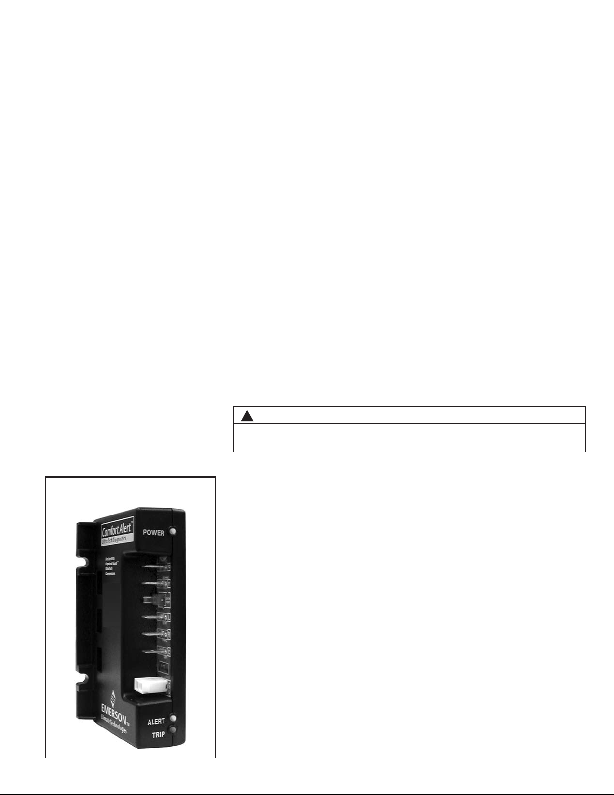
FIGURE 1
LED DESCRIPTION
Manifold Hoses:
-Service Pressure Rating of 800 PSIG
Recovery Cylinders:
-400 PSIG Pressure Rating
-Dept. of Transportation 4BA400 or BW400
!
CAUTION
R-410A systems operate at higher pressures than R-22 systems. Do not use
R-22 service equipment or components on R-410A equipment.
D. COMFORT ALERT™ SYSTEM (2-STAGE MODELS ONLY)
1. Comfort Alert™
The Comfort Alert™ diagnostics module is for troubleshooting air conditioning system failures. By monitoring and analyzing data from the compressor and the thermostat demand, the module can accurately detect the cause of electrical and system-related failures without any external sensors. A flashing LED indicator communicates the ALERT code and guides the service technician more quickly and accurately to the root cause of a problem.
POWER LED (Green): indicates voltage is present at the power connection of the
module.
ALERT LED (Yellow): communicates an abnormal system condition through a
unique flash code. The ALERT LED will flash a number of times consecutively,
pause and then repeat the process. The number of consecutive flashes, defined
as the Flash Code, correlates to a particular abnormal condition. Detailed
descriptions of specific ALERT Flash Codes are shown in the Comfort Alert
Diagnosis Chart in this manual.
TRIP LED (Red): indicates there is a demand signal from the thermostat but no
current to the compressor is detected by the module. The TRIP LED typically
indicates the compressor internal overload protector is open or may indicate
missing high voltage supply power to the compressor.
When an abnormal system condition occurs, the Comfort Alert module displays the
appropriate ALERT and/or TRIP LED. The yellow ALERT LED will flash a number
7
of times consecutively, pause and then repeat the process. To identify a Flash
Code number, count the number of consecutive flashes.
IMPORTANT: Every time the module powers up, the last ALERT Flash Code that
occurred prior to shut down is displayed for one minute. The module will continue to
display the flash code until the condition returns to normal or if 24VAC power is
removed from the module.
The control box cover allows access to the Comfort Alert™ status LEDs. An abbreviated Comfort Alert™ diagnostic chart is provided on the control box cover.
2. High Pressure Control (HPC)
The high pressure control (HPC) keeps the compressor from operating in pressure
ranges, which can cause damage to the compressor. This is an auto-reset control that
opens near 610 PSIG and closes once the system pressure drops below 420 PSIG.
The high pressure control is wired in the 24VAC side of the control circuitry.
3. Low Pressure Control (LPC)
The low pressure control (LPC) keeps the compressor from operating in pressure
ranges that can cause damage to the compressor. This is an auto-reset control that
opens near 90 PSIG and closes once the system pressure rises above 135 PSIG.
The low pressure control is wired in the common side of the control circuitry.
4. Comfort Alert With Active Protection
A two-stage cooling thermostat is required for proper unit operation.
Manufacturer recommends the use of thermostats that provide active compressor pro-
tection via the L terminal when the Comfort-Alert module on the unit is connected to the
L terminal on the thermostat.
The Comfort Alert diagnostics module diagnoses system and electrical problems in
the air conditioning system. Abnormal conditions are indicated by flashing
ALERT codes on the yellow LED on the Comfort Alert module. The flash codes are
transmitted to the thermostat when the L terminal on the Comfort Alert Module is
connected to the L terminal on the thermostat. The compatible thermostat displays a
CHECK SYSTEM icon that flashes at the same rate as the yellow ALERT LED on the
Comfort Alert module.
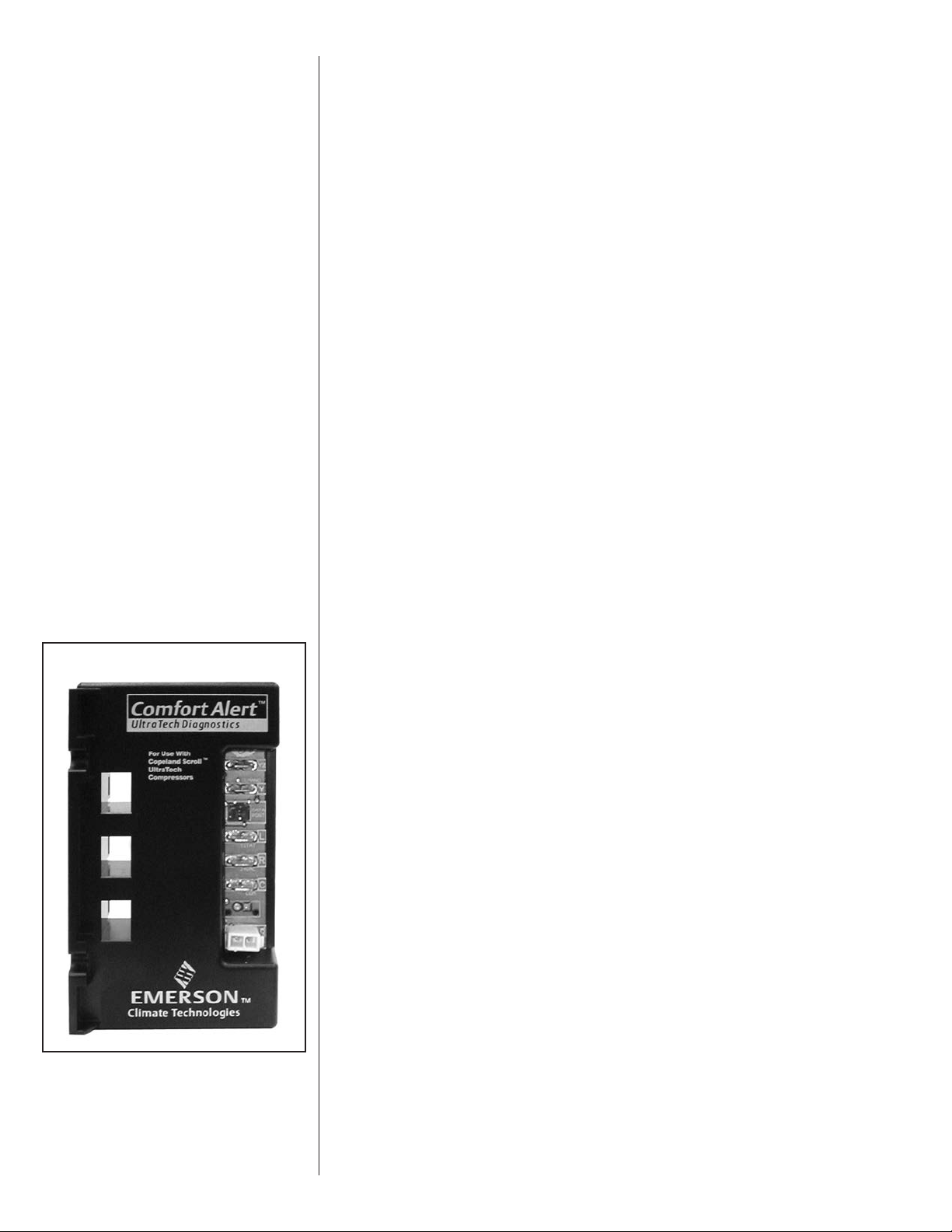
FIGURE 2
NOTE: The Comfort Alert™ module does not provide safety protection! It does not dis-
connect power from the unit.
Comfort Alert™ Flash Codes
1 – Long Run Time
2 – System Pressure Trip
3 – Short Cycling
4 – Locked Rotor
5 – Open Circuit
6 – Open Start Circuit (single phase) – missing phase (3-phase)
7 – Open Run Circuit (single phase) – reverse phase (3-phase)
8 – Welded Contactor
9 – Low Voltage
See Figures 42 and 43 (Comfort Alert Diagnostic Charts) for more troubleshooting information.
8

Active protection occurs under the following conditions:
1) Flash Code 2 - System Pressure Trip
Condition: Four consecutive compressor protector trips occur where the
average run time until trip is between 1 minute and 15 minutes
Possible causes:
Low suction pressure
• Low pressure switch is open
• Low system charge
Blocked condenser coil
Restricted condenser air flow
Active Thermostat Reaction:
2) Flash Code 3 - Short Cycling
Condition: A pattern of short cycling emerges where the run time for the
previous four cycles is less than three minutes each.
Possible causes:
Active Thermostat Reaction:
3) Flash Code 4 - Locked Rotor
Condition: The compressor internal overload trips where the average run
time is less than 15 seconds.
Possible causes:
Active Thermostat Reaction:
The thermostat will cycle the system ON for 5 minutes and OFF for
five minutes to verify system fault. If this ON/OFF cycling repeats for
30 ten-minute cycles, the thermostat concludes there is a system
problem and implements a hard lockout.
High head pressure
• High pressure switch is open
• System overcharged
• Non-condensables in system
Faulty thermostat
Intermittent contactor
The thermostat will cycle the system ON for 5 minutes and OFF for
five minutes to verify the system fault. If this ON/OFF cycling repeats for
30 ten-minute cycles, the thermostat concludes there is a system
problem and implements a hard lockout.
Bad run capacitor
Low line voltage
Excessive liquid refrigerant in compressor
Compressor bearings are seized
Faulty hard start components
The thermostat implements a hard lockout once this error is sensed.
4) Flash Code 6 - Open Start Circuit
Condition: Current is detected in the run circuit but not in the start circuit.
Possible causes:
Bad run capacitor
Open circuit in compressor start wiring or connections.
Compressor start winding is damaged
Active thermostat reaction:
The thermostat implements a hard lockout after 3 hours.
5) Flash Code 7 - Open Run Circuit
Condition: Open circuit in compressor run wiring or connections.
Compressor run winding is damaged.
Active Thermostat Reaction:
The thermostat implements a hard lockout after 3 hours.
9
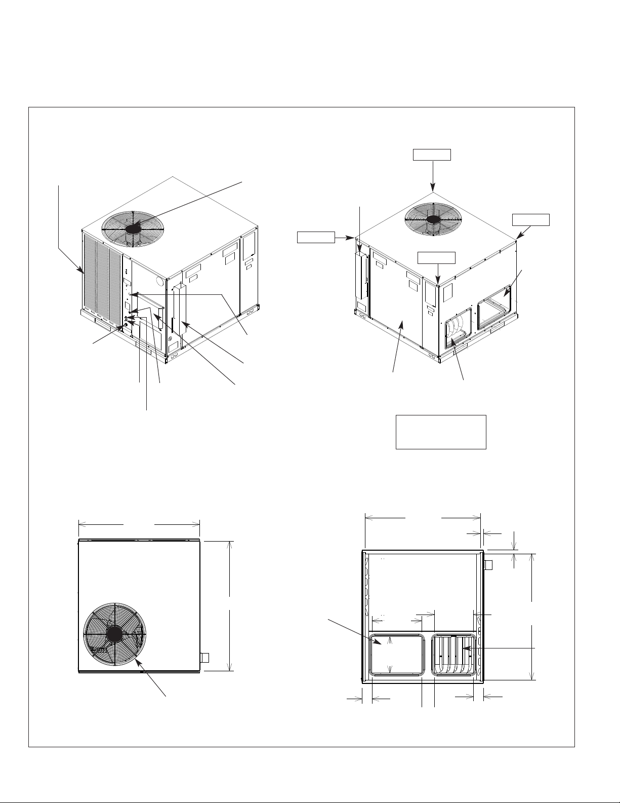
V. UNIT DIMENSIONS
FOR CLEARANCES
SEE FIGURE 3.
FIGURE 3
OUTDOOR COIL
PROTECTIVE GRILLE
OUTDOOR FAN GRILLE
AND COMPRESSOR ACCESS
29% ± 2%
FLUE
EXHAUST
30% ± 2%
20% ± 2%
21% ± 2%
SIDE
RETURN
DUCT
OPENING
THREADED
PVC CONDENSATE
DRAIN CONNECTION
(3/4 NPT)
SUCTION PRESSURE
SERVICE PORT
LIQUID PRESSURE
SERVICE PORT
TOP VIEW
479⁄16”
FIELD CONTROL
WIRE ENTRANCE
FLUE EXHAUST
HOOD
COMBUSTION AIR
INLET HOOD
5013⁄16”
FIELD POWER
WIRE ENTRANCE
BOTTOM
RETURN
DUCT
OPENING
BLOWER/EVAPORATOR
ACCESS PANEL
CORNER WEIGHTS
% OF TOTAL UNIT
BOTTOM VIEW
451⁄16”
INSIDE
191⁄2”
141⁄4”
TYP.
SIDE SUPPLY DUCT
OPENING
WEIGHT
13⁄16”
TYP.
153⁄8”
11⁄2”
TYP.
497⁄16”
INSIDE
BOTTOM
SUPPLY
DUCT
OPENING
10
OUTDOOR FAN
GRILLE & COMPRESSOR
ACCESS
313⁄16”
33⁄16”
49⁄10”
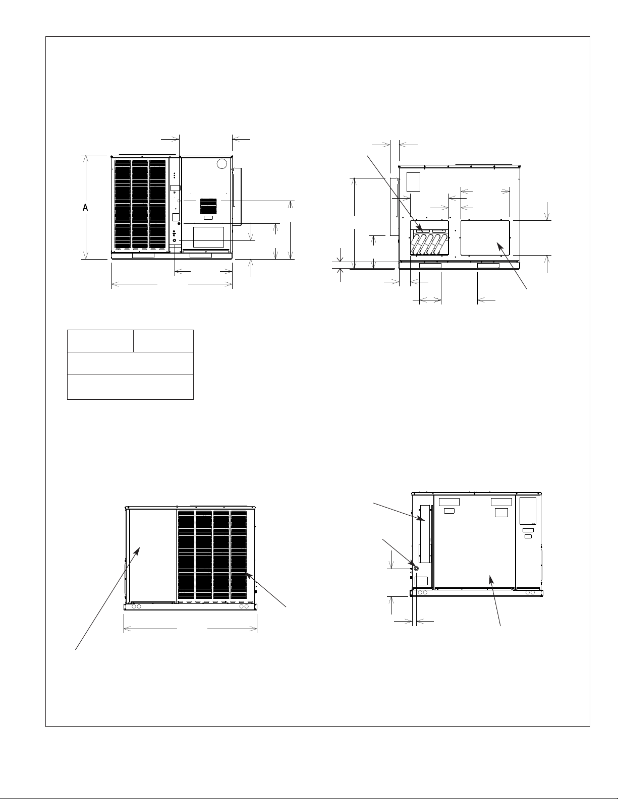
FIGURE 3 (CONTINUED)
MODEL
RGEA16
024
036, 048,
060
FRONT VIEW
471⁄2”
“A”
HEIGHT
3515⁄16”
41
207⁄8”
2211⁄16”
75⁄16”
227⁄8”
1315⁄16”
21⁄2”
SIDE
SUPPLY
DUCT
OPENING
3515⁄16”
BACK VIEW
39⁄16”
15”
191⁄8”
47⁄8”
131⁄4”
47⁄16”
81⁄2”
TYP.
SHOWN WITH DUCT COVERS REMOVED.
143⁄16”
TYP.
133⁄4”
TYP.
SIDE
RETURN
DUCT
OPENING
FILTER ACCESS PANEL
(FOR UNIT MOUNTED FILTER
ACCESSORY)
SIDE VIEW
527⁄16”
OUTDOOR
COIL PROTECTIVE
GRILLE
SIDE VIEW
FLUE
EXHAUST
HOOD
GAS
SUPPLY
ENTRANCE
1015⁄16”
111⁄16”
BLOWER/
EVAPORATOR
ACCESS PANEL
11
VI. INSTALLATION
A. GENERAL
1. PRE-INSTALLATION CHECK-POINTS — Before attempting any installation, carefully consider the following points:
Structural strength of supporting members
(Rooftop Installation)
Clearances and provision for servicing
Power supply and wiring
Gas supply and piping
Air duct connections and sizing
Drain facilities and connections
Location for minimum noise and vibration
2. LOCATION CONSIDERATIONS (CORROSIVE ENVIRONMENT)
The metal parts of this unit may be subject to rust or deterioration if exposed to a
corrosive environment. This oxidation could shorten the equipment’s useful life.
Corrosive elements include, but are not limited to, salt spray, fog or mist in seacoast
areas, sulphur or chlorine from lawn watering systems, and various chemical contaminants from industries such as paper mills and petroleum refineries.
If the unit is to be installed in an area where contaminants are likely to be a
problem, give special attention to the equipment location and exposure.
1. Avoid having lawn sprinkler heads spray directly on the unit cabinet.
2. In coastal areas locate the unit on the side of the building away from the water-
front.
3. Shielding by a fence or shrubs may give some protection.
WARNING
!
DISCONNECT ALL POWER TO UNIT BEFORE STARTING MAINTENANCE.
FAILURE TO DO SO CAN CAUSE ELECTRICAL SHOCK RESULTING IN PERSONAL INJURY OR DEATH.
1. Frequent washing of the cabinet, fan blade and coil with fresh water will remove
most of the salt or other contaminants that build up on the unit.
2. Regular cleaning and waxing of the cabinet with a good automobile polish will provide some protection.
3. Use a good liquid cleaner several times a year to remove matter that will not wash
off with water.
Several different types of protective coatings are offered in some areas. These coatings
may provide some benefit, but the effectiveness of such coating materials cannot be verified by the equipment manufacturer.
The best protection is frequent cleaning, maintenance and minimal exposure to
contaminants.
B. OUTSIDE INSTALLATION
WARNING
!
THESE UNITS ARE DESIGNED CERTIFIED FOR OUTDOOR INSTALLATION
ONLY. INSTALLATION INSIDE ANY PART OF A STRUCTURE CAN RESULT IN
INADEQUATE UNIT PERFORMANCE AS WELL AS PROPERTY DAMAGE.
INSTALLATION INSIDE CAN ALSO CAUSE RECIRCULATION OF FLUE PRODUCTS INTO THE CONDITIONED SPACE RESULTING IN PERSONAL INJURY
OR DEATH.
12
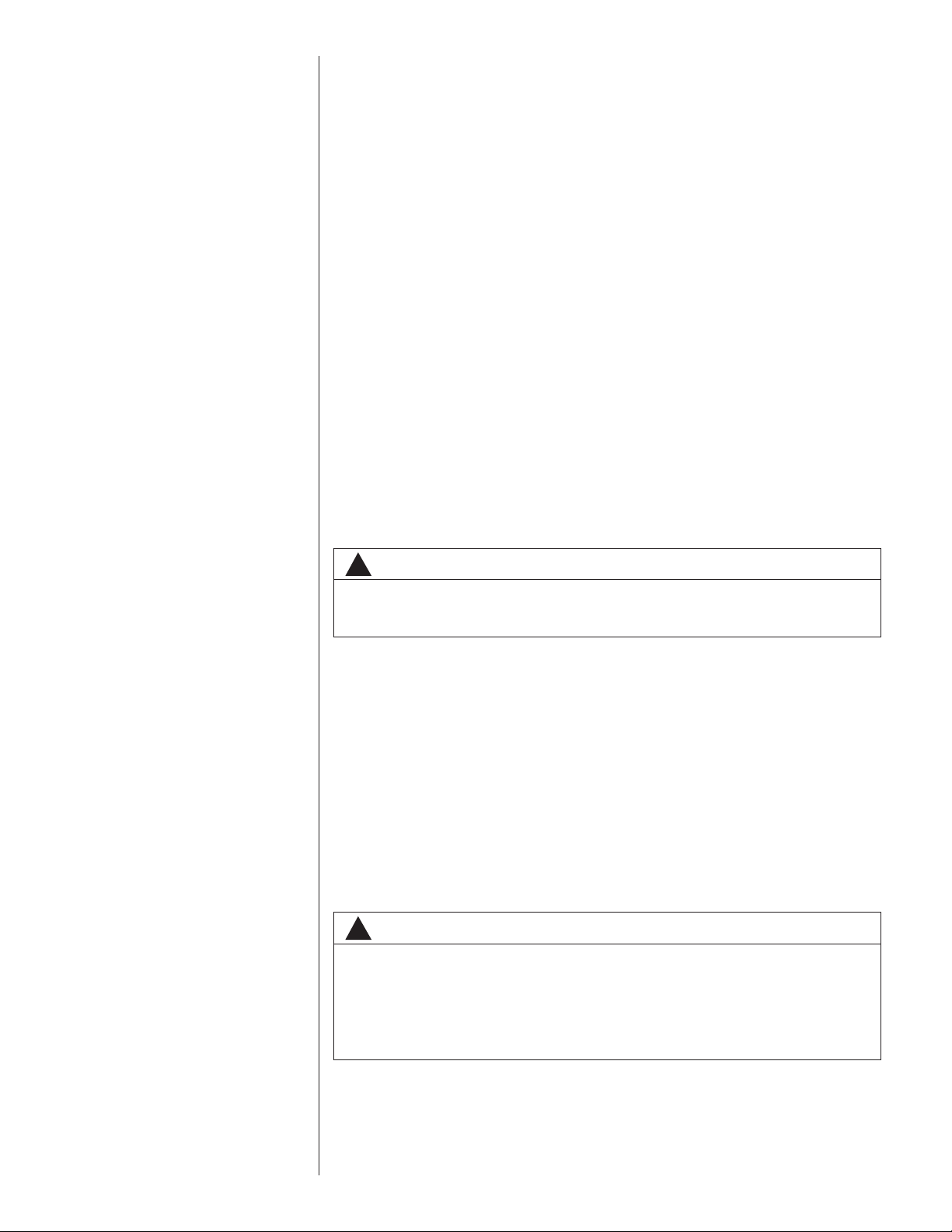
(Typical outdoor slab installation is shown in Figure 4.)
1. Select a location where external water drainage cannot collect around unit.
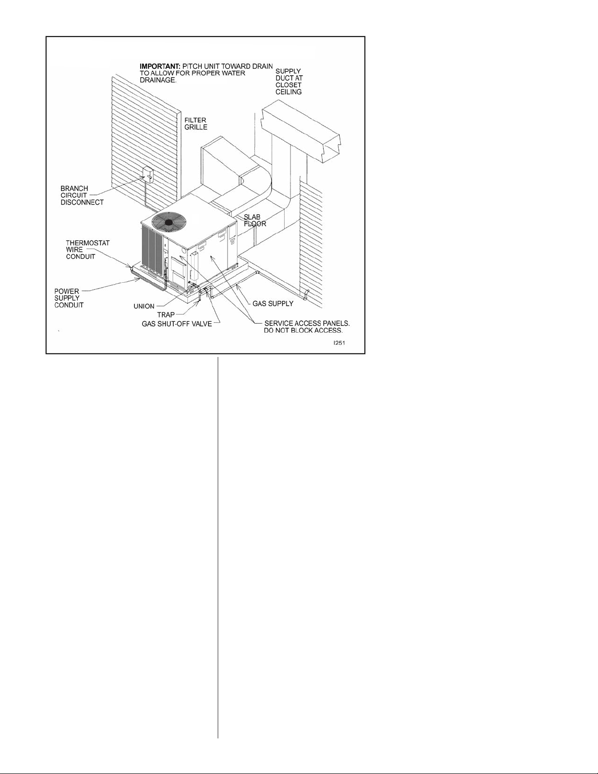
FIGURE 4
OUTSIDE SLAB INSTALLATION. CLOSET DISTRIBUTION SYSTEM. SLAB FLOOR
CONSTRUCTION
2. Provide a slab sufficiently high enough above grade to prevent surface water from
entering the unit. Where snowfall is anticipated, mount the unit above the anticipated maximum snow depth for your area. Do not locate unit in an area where excessive snow drifting may block combustion air inlet.
3. Pitch the slab approximately
1
⁄2” so that the unit will be pitched toward the drain. See
Figure 5.
4. The location of the unit should be such as to provide proper access for inspection
and servicing as shown in Figure 11.
5. Locate unit where operating sounds will not disturb owner or neighbors. The slab
should be isolated from the foundation wall.
6. Locate unit so roof runoff water does not pour directly on the unit. Provide gutter or
other shielding at roof level.
C. ATTACHING EXHAUST AND COMBUSTION AIR INLET HOODS
IMPORTANT: Do not operate this unit without the exhaust and combustion air inlet
hood properly installed. These hoods are shipped in a carton in the return air compartment inside the unit and must be attached when the unit is installed. See Figure 6.
To attach exhaust and combustion air inlet hood:
1. Remove 3 screws securing filter access panel and remove filter access panel. For location of filter access panel, see Figure 3.
2. Remove both exhaust and combustion air inlet hoods from their carton, located inside
the return air compartment.
3. Attach filter access panel.
4. Attach the combustion air inlet hood and the exhaust hood each with 4 screws as shown
in Figure 6. Screws are in parts bag shipped in the burner compartment.
5. Vent the unit using the flue exhaust hood, as supplied from the factory, without alteration
or addition. The only exception is with factory approved additions. Consult your local utility or other authority having jurisdiction for accepted venting techniques.
13
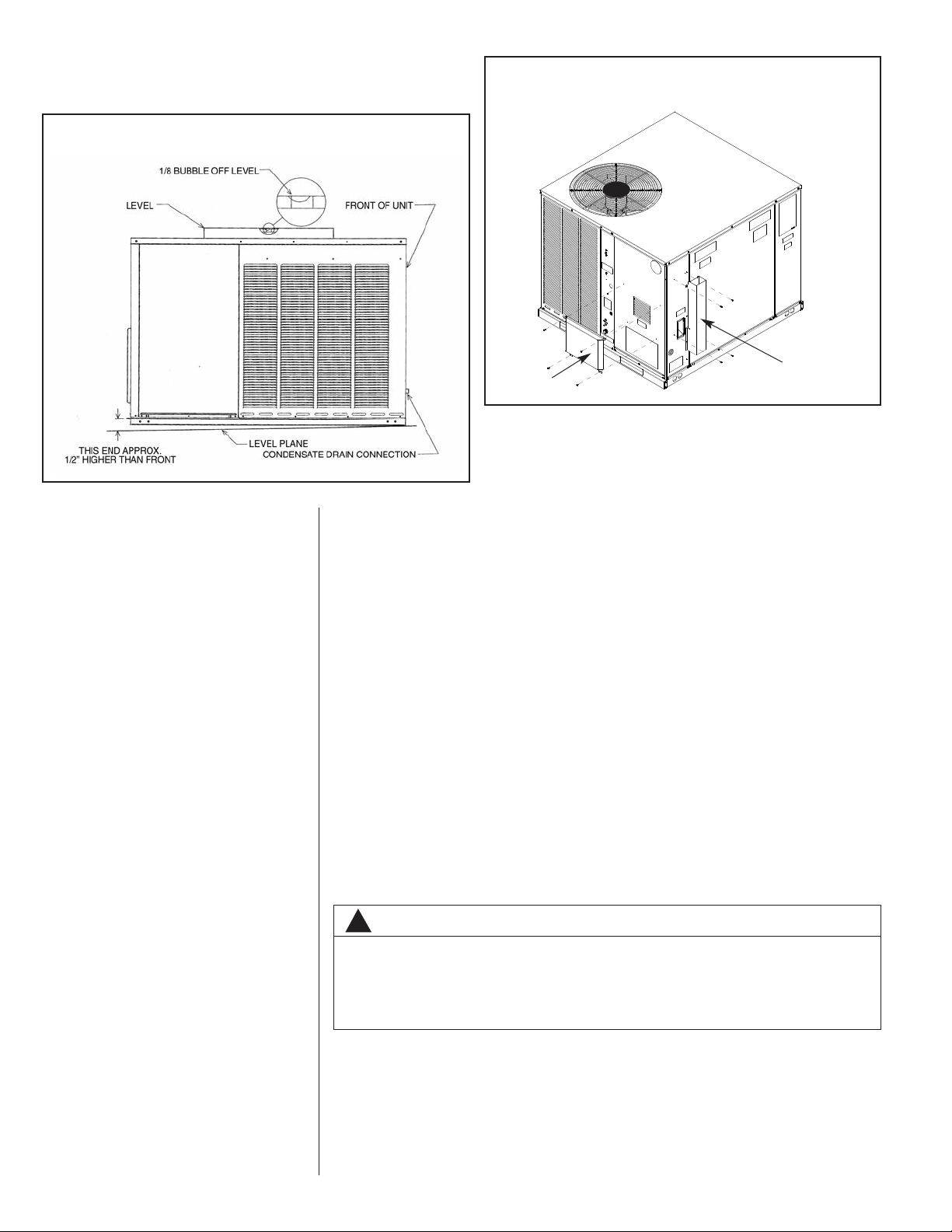
FIGURE 5
PITCHING UNIT TO INSURE PROPER CONDENSATE DRAINAGE.
FIGURE 6
COMBUSTION AIR INLET HOOD & EXHAUST HOOD
INSTALLATION
EXHAUST
HOOD W/(4)
SCREWS
I655
COMBUSTION
AIR INLET
HOOD W/(4)
SCREWS
D. COVER PANEL INSTALLATION/CONVERSION PROCEDURE
1. HORIZONTAL TO DOWNFLOW
a. Remove screws and covers from the supply and return bottom sections. NOTE:
Rotate the supply cover 90° and remove.
b. Install gasket (supplied with parts bag) around perimeter of cover on the insulated
side. See Figure 8.
c. Secure covers to the side of the unit using existing screws and those supplied in
the parts bag.
2. DOWNFLOW TO HORIZONTAL
a. Remove screws and covers from the supply and return bottom sections.
b. Install gasket (supplied with parts bag) around perimeter of cover as illustrated in
Figure 7.
c. Install covers in the unit bottom with the insulated side up. NOTE: Supply cover
must be inserted through supply opening with narrow side toward unit. Once
cover is through opening, rotate 90° and slip back flange of cover under tab at the
back of bottom duct opening. See Figure 10.
d. Secure supply cover to base of unit with 2 screws, engaging prepunched holes in
raised duct opening flange.
e. Secure return covers to base of unit with screws engaging prepunched holes in
raised duct opening flange.
14
WARNING
!
THIS UNIT MUST NOT BE INSTALLED DIRECTLY ON WOOD FLOORING, CLASS
A, CLASS B OR CLASS C ROOF COVERING MATERIALS, OR ANY OTHER COMBUSTIBLE STRUCTURE EXCEPT AS SPECIFIED IN FIGURE 15. FAILURE TO
ADHERE TO THIS WARNING CAN CAUSE A FIRE OR EXPLOSION RESULTING
IN PROPERTY DAMAGE, PERSONAL INJURY OR DEATH.
E.CLEARANCES
The following minimum clearances must be observed for proper unit performance and
serviceability. See Figure 11.
1. Provide 48” minimum clearance at front of the unit. Provide 24” minimum clearance
on right side of unit. If economizer is used, a 24” minimum clearance is required on
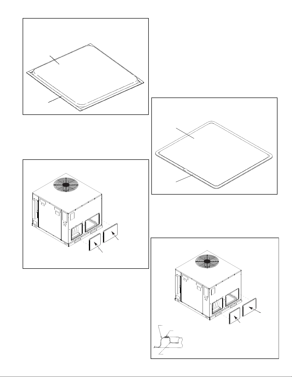
FIGURE 5
COVER GASKET DETAILFOR UNITS SHIPPED FOR DOWNFLOW
APPLICATION BEING CONVERTED TO SIDE DISCHARGE
TAPE
AROUND FLANGE
SUPPLY/RETURN
AIR COVER
FIGURE 6
COVER GASKET DETAILFOR UNITS SHIPPED FOR SIDE DISCHARGE
APPLICATION BEING CONVERTED TO DOWNFLOW
TAPE
AROUND FLANGE
SUPPLY/RETURN
AIR COVER
I654
FIGURE 7
DUCT COVER INSTALLATION SIDE MOUNTING
I264
RETURN
DUCT COVER
(ATTACH WITH 6 SCREWS)
SUPPLY
DUCT COVER
(ATTACH WITH 6 SCREWS)
I
FIGURE 8
DUCT COVER INSTALLATION BASE PAN MOUNTING
I265
BASE PAN
SUPPLYDUCT
COVER
*
(INSULATION
SIDE UP),
ATTACH WITH
TWO SCREWS.
RETURN
DUCT
COVER
(INSULATION
SIDE UP ,
ATTACH
WITH 4
SCREWS)
SUPPLYDUCT
COVER
*
ROTATE SUPPLY COVER 90° AFTER IT IS INSERTED
THROUGH OPENING. SLIP FLANGE OF COVER
UNDER LANCE AT BACK OF BOTTOM SUPPLY DUCT
OPENING. SEE DETAILAT LEFT. THEN SECURE
COVER BY INSTALLING 2 SCREWS USING HOLE
NEAREST THE OUTSIDE OF UNIT.
LANCE AT BACK OF BOTTOM
SUPPLYDUCT OPENING
FIGURE 7
COVER GASKET DETAIL FOR UNITS SHIPPED FOR DOWNFLOW
APPLICATION BEING CONVERTED TO SIDE DISCHARGE
FIGURE 8
COVER GASKET DETAIL FOR UNITS SHIPPED FOR SIDE DISCHARGE
APPLICATION BEING CONVERTED TO DOWNFLOW
FIGURE 9
DUCT COVER INSTALLATION SIDE MOUNTING
FIGURE 10
DUCT COVER INSTALLATION BASE PAN MOUNTING
15
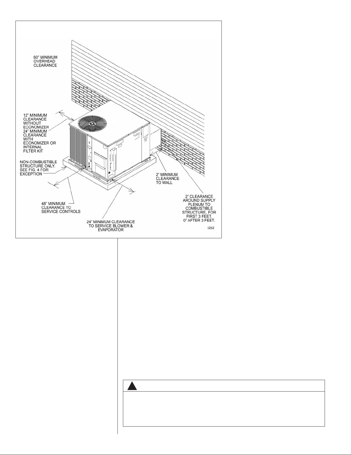
FIGURE 11
CLEARANCES
left side of unit. (See Figure 11.) If no economizer is required, then a 12” clearance
is required on left side of unit.
2. Provide 60” minimum clearance between top of unit and maximum 3 foot overhang.
3. Unit is design certified for 2” minimum clearance between supply duct and a combustible structure for the first 3 feet of duct. 0” clearance is allowed after 3 feet.
F. ROOFTOP INSTALLATION
1. Before locating the unit on the roof, make sure that the roof structure is adequate to
support the weight involved. (See electrical & physical tables in this book for weight
of unit.) THIS IS VERY IMPORTANT AND THE INSTALLER’S RESPONSIBILITY.
2. For rigging and roofcurb details, see Figures 16, 17, and 18.
3. The location of the unit on the roof should be such as to provide proper access for
inspection and servicing.
IMPORTANT: If unit will not be put into service immediately, block off supply and return
air openings to prevent excessive condensation.
G. DUCTWORK
The installing contractor should fabricate ductwork in accordance with local codes. Use
industry manuals as a guide when sizing and designing the duct system. Contact Air
Conditioning Contractors of America, 1513 16th St. N.W., Washington, D.C. 20036.
WARNING
!
DO NOT, UNDER ANY CIRCUMSTANCES, CONNECT RETURN DUCTWORK TO
ANY OTHER HEAT PRODUCING DEVICE SUCH AS FIREPLACE INSERT,
STOVE, ETC. UNAUTHORIZED USE OF SUCH DEVICES MAY RESULT IN FIRE,
CARBON MONOXIDE POISONING, EXPLOSION, PERSONAL INJURY, OR
PROPERTY DAMAGE.
16
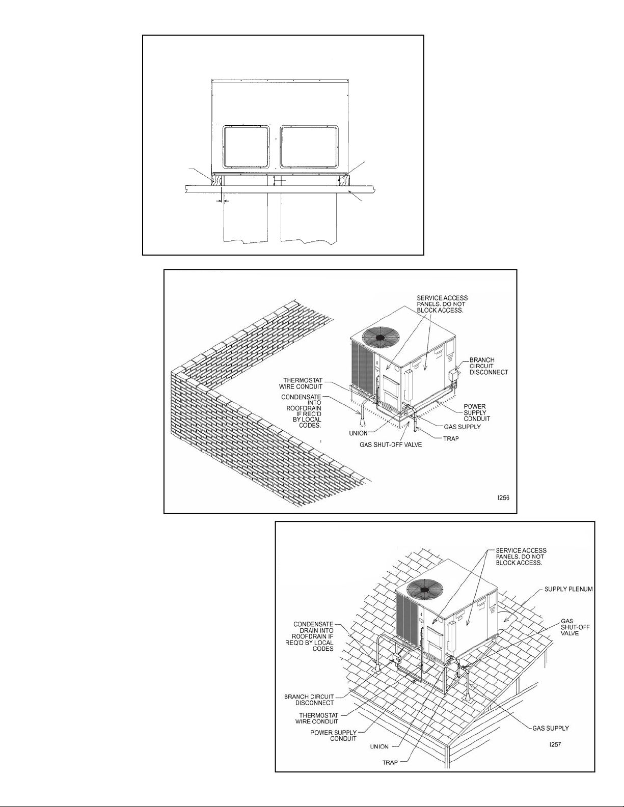
FIGURE 10
EXCEPTION TO NON-COMBUSTIBLE FLOORING REQUIREMENT
I458
BOTH ENDS
MUST BE
OPEN FOR
DOWNFLOW
OR SIDEFLOW
DUCTWORK
TO PROVIDE
VENTILATION
COMBUSTIBLE
STRUCTURE
1” MIN.
NOMINAL
4 x 4 TIMBER
(SIDES ONLY)
SIDEFLOW
SUPPLY
PLENUM
CONNECTION
SUPPLY
PLENUM
(DOWNFLOW)
RETURN PLENUM
(DOWNFLOW)
SIDEFLOW
RETURN PLENUM
CONNECTION
3-1/2” MIN.
FIGURE 12
EXCEPTION TO NON-COMBUSTIBLE FLOORING REQUIREMENT
FIGURE 13
FLAT ROOFTOP INSTALLATION, ATTIC OR DROP CEILING DISTRIBUTING SYSTEM. MOUNTED ON
ROOFCURB, PITCH UNIT TOWARD DRAIN.
FIGURE 14
PITCHED ROOFTOP INSTALLATION, ON ANGLE-IRON STAND, SIDE FLOW DUCTWORK,
ATTIC OR DROP CEILING
DISTRIBUTING SYSTEM.
PITCH UNIT TOWARD DRAIN.
17
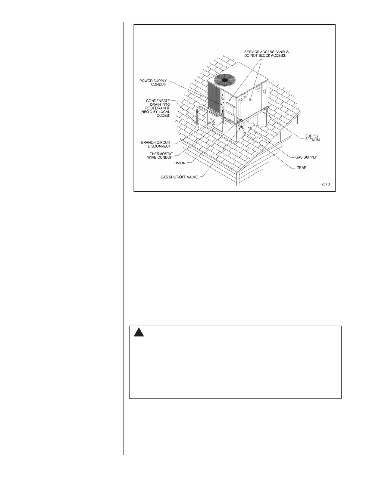
FIGURE 15
PITCHED ROOFTOP INSTALLATION, ON ROOFJACK, DOWNFLOW DUCTWORK, ATTIC OR
DROP CEILING DISTRIBUTING SYSTEM. PITCH UNIT TOWARD DRAIN.
Place the unit as close to the conditioned space as possible allowing clearances as indicated. Run ducts as directly as possible to supply and return outlets. Use of non-flammable weatherproof flexible connectors on both supply and return connections at unit to
reduce noise transmission is recommended.
On ductwork exposed to outside temperature and humidity, use a minimum of 2” of
insulation and a vapor barrier. Distribution system in attic, furred space or crawl space
should be insulated with at least 2” of insulation.
cient for ductwork inside the air conditioned space.
Provide balancing dampers for each branch duct in the supply system. Properly support
ductwork from the structure.
IMPORTANT: In the event that the return air ducts must be run through an “unconfined”
space containing other fuel burning equipment, it is imperative that the user/homeowner
must be informed against future changes in construction which might change this to a
“confined space.” Also, caution the user/homeowner against any future installation of
additional equipment (such as power ventilators, clothes dryers, etc., within the existing
unconfined and/or confined space which might create a negative pressure within the
vicinity of other solid, liquid, or gas fueled appliances.
1
⁄2” to 1” thick insulation is usually suffi-
18
H. RETURN AIR
WARNING
!
NEVER ALLOW PRODUCTS OF COMBUSTION OR THE FLUE PRODUCTS TO
ENTER THE RETURN AIR DUCTWORK, OR THE CIRCULATING AIR SUPPLY.
ALL RETURN DUCTWORK MUST BE ADEQUATELY SEALED AND SECURED
TO THE FURNACE WITH SHEET METAL SCREWS, AND JOINTS TAPED. ALL
OTHER DUCT JOINTS MUST BE SECURED WITH APPROVED CONNECTIONS
AND SEALED AIRTIGHT.
FAILURE TO PREVENT PRODUCTS OF COMBUSTION FROM BEING CIRCULATED INTO THE LIVING SPACE CAN CREATE POTENTIALLY HAZARDOUS
CONDITIONS, INCLUDING CAROBON MONOXIDE POISONING THAT COULD
RESULT IN PERSONAL INJURY OR DEATH.
 Loading...