

Rheem Residential Solar Water Heater with Heat Exchanger, Residential Solar Heat Exchang Use & Care Manual
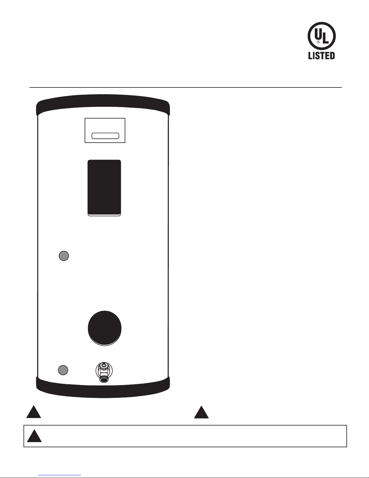
Residential Solar Water Heater with Heat Exchanger
USE & CARE MANUAL
WITH INSTALLATION INSTRUCTIONS FOR THE CONTRACTOR
The purpose of this manual is twofold: one, for the installing
contractor, to provide requirements and recommendations
for the proper installation and adjustment of the water
heater; and two, for the owner-operator, to explain the
features, operation, safety precautions, maintenance and
trouble shooting of the water heater. This manual also
includes a parts list.
It is imperative that all persons who are expected to install,
operate or adjust this water heater read the instructions
carefully so that they may understand how to do so.
ALTERNATE-ENERGY WATER-STORAGE TANK
52L6
Do Not Destroy this Manual. Please read carefully
!
and keep in a safe place for Future Reference.
CALIFORNIA PROPOSITION 65 WARNING: This product contains chemicals known to the State of California to cause
!
cancer, birth defects or other reproductive harm.
Printed in USA
Recognize this symbol as an Indication of Important
!
Safety Information!
AP12816-4 (06/11)
!
!
!
General Safety Precautions
Be sure to read and understand the entire Use & Care Manual before attempting to install
or operate this water heater.
low these warnings could result in serious bodily injury or death. Should you have problems understanding the instructions in this manual, or have any
questions, STOP, and get help from a qualified installer, service technician, or the local electric utility.
It may save you time and cost. Pay particular attention to the General Safety Precautions. Failure to fol-
DANGER!
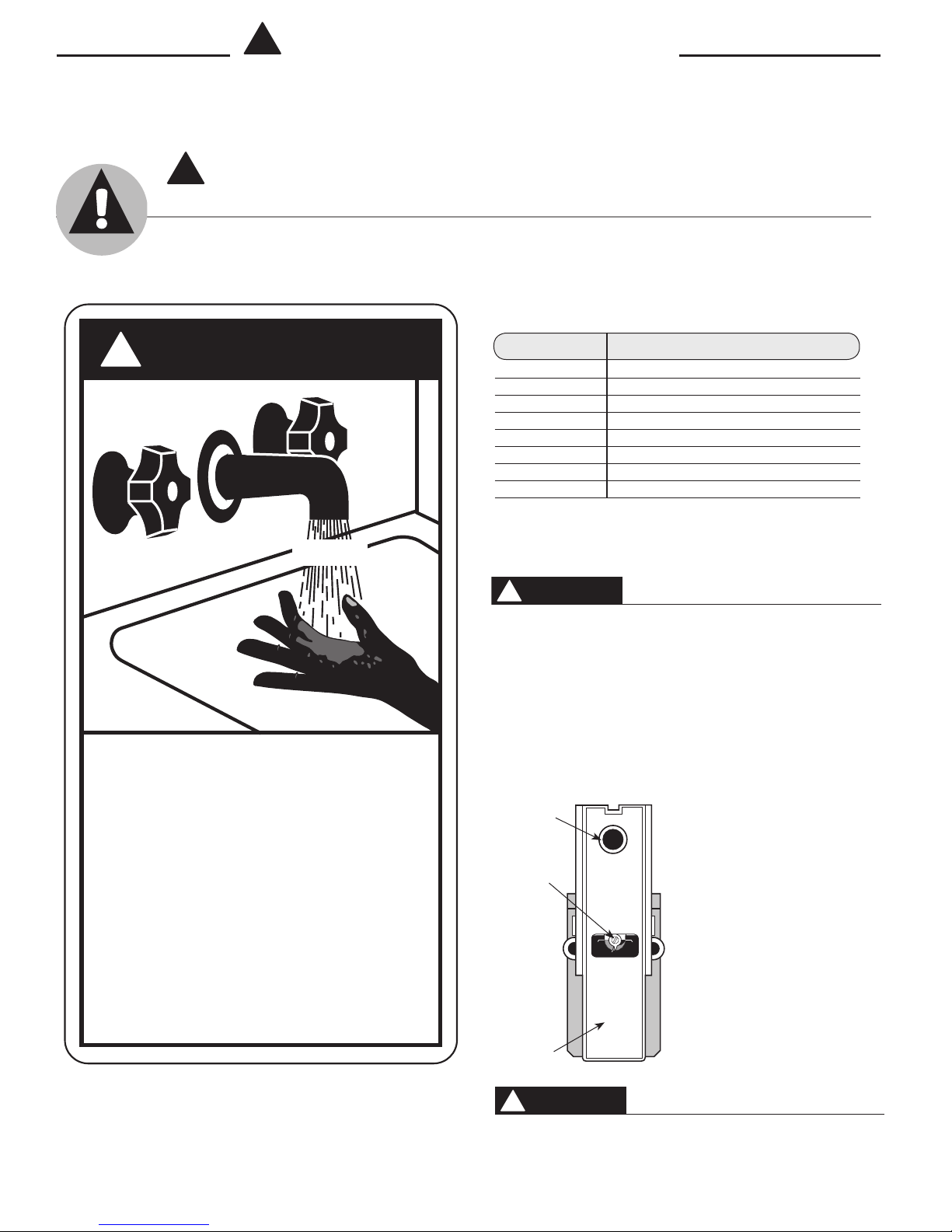
WATER TEMPERATURE SETTING
Safety and energy conservation are factors to be considered when selecting the water temperature setting of a
water heater’s gas control. Water temperatures above 125°F can cause severe burns or death from scalding. Be
sure to read and follow the warnings outlined on the label pictured below. This label is also located on the water
heater.
Time/Temperature Relationship in Scalds
!
D A N G E R
HOT
BURN
Water temperature over 125°F can
cause severe burns instantly or
death from scalds.
Children, disabled and elderly are
at highest risk of being scalded.
See instruction manual before
setting temperature at water
heater.
Feel water before bathing or
showering.
Temperature limiting valves are
available, see manual.
Water Temperature Time To Produce a Serious Burn
120°F (49°C) More than 5 minutes
125°F (52°C) 11/2 to 2 minutes
130°F (54°C) About 30 seconds
135°F (57°C) About 10 seconds
140°F (60°C) Less than 5 seconds
145°F (63°C) Less than 3 seconds
150°F (66°C) About 11/2 seconds
155°F (68°C) About 1 second
Table courtesy of Shriners Burn Institute
The chart shown above may be used as a guide in determining the proper
water temperature for your home.
DANGER
NOTICE: Households with small children, disabled, or
elderly persons may require a 120°F or lower thermostat setting to prevent contact with “HOT” water.
The temperature of the water in the heater is regulated by the adjustable
surface mounted thermostat located behind the Jacket Access Panel. To
comply with safety regulations the thermostat was set at 120° F before the
water heater was shipped from the factory.
Reset
Button
Thermostat Dial
Pointer
Thermostat
Protective
Cover
(66°C)
TURN OFF
SERVICING
T
E
S
E
R
125°F
POWER
BEFORE
R
E
S
E
T
90°F150°F
(32°C)
(52°C)
The illustration at left shows the
temperature adjustment dial used for
setting the water temperature. Refer
to Operation section of this manual
for detailed instructions in how to
adjust the thermostat.
Notice: Mixing valves are available for reducing
point of use water temperature by mixing hot and
cold water in branch water lines. Contact a licensed
plumber or the local plumbing authority for further
information.
DANGER
!
There is a Hot Water SCALD Potential if the thermostat is
set too high.
2
Introduction
The location chosen for the water heater must take into consideration the following:
LOCAL INSTALLATION REGULATIONS
Solar storage or solar electric storage water heaters must be installed in accordance with these instructions, local codes, utility
company requirements or, in the absence of local codes, the latest
edition of the National Electrical Code. It is available from some
local libraries or can be purchased from the National Fire Prevention Association, 1 Batterymarch Park, Quincy, MA 02269 as
booklet ANSI/NFPA 70.
LOCATION
Locate the water heater or storage tank as determined by the type
of solar system that is being installed. The area should be clean,
dry and as near as practical to the area of greatest heated water
demand. The piping should be insulated. Long uninsulated hot
water lines can waste energy and water. Place the water heater in
such a manner that the thermostat and element access panels can
be removed to permit inspection and servicing such as removal of
elements or checking controls. The water heater and water lines
should be protected from freezing temperatures. Do not install the
water heater in outdoor, unprotected areas.
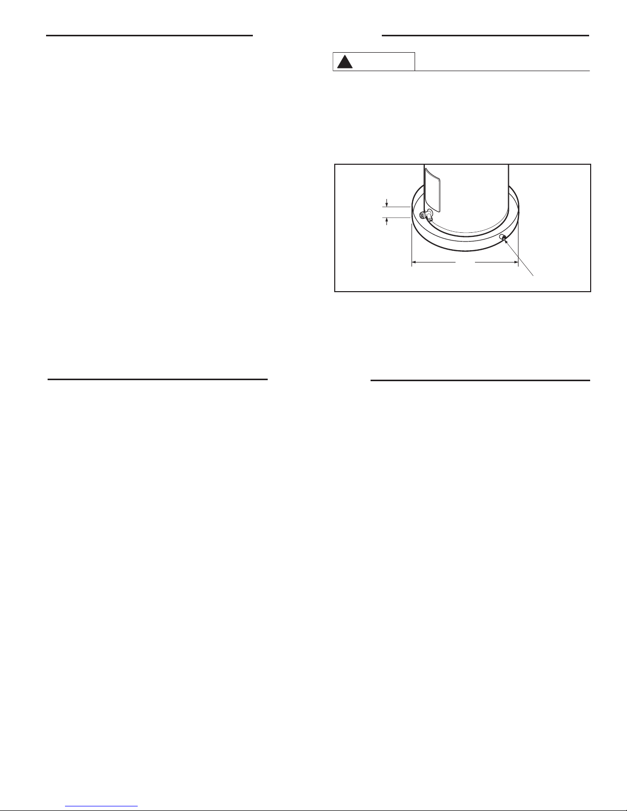
CAUTION
!
The water heater should not be located in an area
where leakage of the tank or connections will result
in damage to the area adjacent to it or to lower floors
of the structure. Where such areas cannot be avoided, it is recommended that a suitable catch pan, adequately drained, be installed under the water heater.
B
A — Diameter of water
heater plus 2" min.
B — Maximum 2"
Figure 1 - Auxiliary Catch Pan
A
To open drain, line
should be at least
3
/4" ID and pitched
for proper drainage.
NOTICE: Auxiliary catch pan installation MUST conform to local codes
Catch Pan Kits are available from the distributor or store where
the water heater was purchased.
.
Installation
This product is for the use in indirect domestic solar water heat-
ing systems — other applications, made without written factory
approval, will void the warranty.
The design and install at ion of solar water heating systems
should only be undertaken by qualified individuals, as such systems involve components and operating principles not found in
standard household plumbing installations. Often high-temperature or toxic fluids are an integral part of solar systems —failure
to understand good design and installation practices can affect
the health and safety of the system user.
Solar storage and solar electric storage water heaters must be
installed in accordance with federal and local codes. The location
chosen for the water heater or storage tank should be as close
as possible to the hot water faucet(s) that are most frequently
used, and the piping should be insulated.
1. INSPECT SHIPMENT — Inspect water heater for possible damage. Check the markings on the rating plate of the water heater
to be cer tain the power supply (Solar Electric Only) corresponds
to that for which the water heater is equipped.
2. THERMAL EXPANSION — Determine if a check valve exists in the
inlet water line. It may have been installed in the cold water line
as a separate back flow preventer, or it may be part of a pressure
reducing valve, water meter or water softener. A check valve
located in the cold water inlet line can cause what is referred
to as a ”closed water system”. A cold water inlet line with no
check valve or back flow prevention device is referred to as an
”open” water system.
As water is heated, it expands in volume and creates an increase
in the pressure within the water system. This action is referred to
as ”thermal expansion”. In an ”open” water system, expanding
water which exceeds the capacity of the water heater flows back
into the city main where the pressure is easily dissipated.
A ”closed water system”, however, prevents the expanding
water from flowing back into the main supply line, and the result of ”thermal expansion” can create a rapid, and dangerous
pressure increase in the water heater and system piping. This
rapid pressure increase can quickly reach the safety setting of
the relief valve, causing it to operate during each heating cycle.
Thermal expansion, and the resulting rapid, and repeated expansion and contraction of components in the water heater and
piping system can cause premature failure of the relief valve,
and possibly the heater itself. Replacing the relief valve will not
correct the problem!
The suggested method of controlling thermal expansion is to install
an expansion tank in the cold water line between the water heater
and the check valve. (refer to Figure 2.) The expansion tank is designed with an air cushion built in that compresses as the system
pressure increases, thereby relieving the over pressure condition
and eliminating the repeated operation of the relief valve. Other
methods of controlling thermal expansion are also available. Contact your installing contractor, water supplier, or plumbing inspector
for additional information regarding this subject.
3. HEAT EXCHANGER LOOP & SOLAR CONNECTIONS — This
heater contains a wrap-around, vented, double wall heat exchanger that provides positive leak detection. Passageways for
the heat transfer fluid are of copper and brass — to prevent
dissimilar-metals corrosion, use only copper panels, piping, and
fittings in the heat exchanger loop. Flow rates through the heat
exchanger should be less than 3 gpm to limit the effects of corrosion.
3
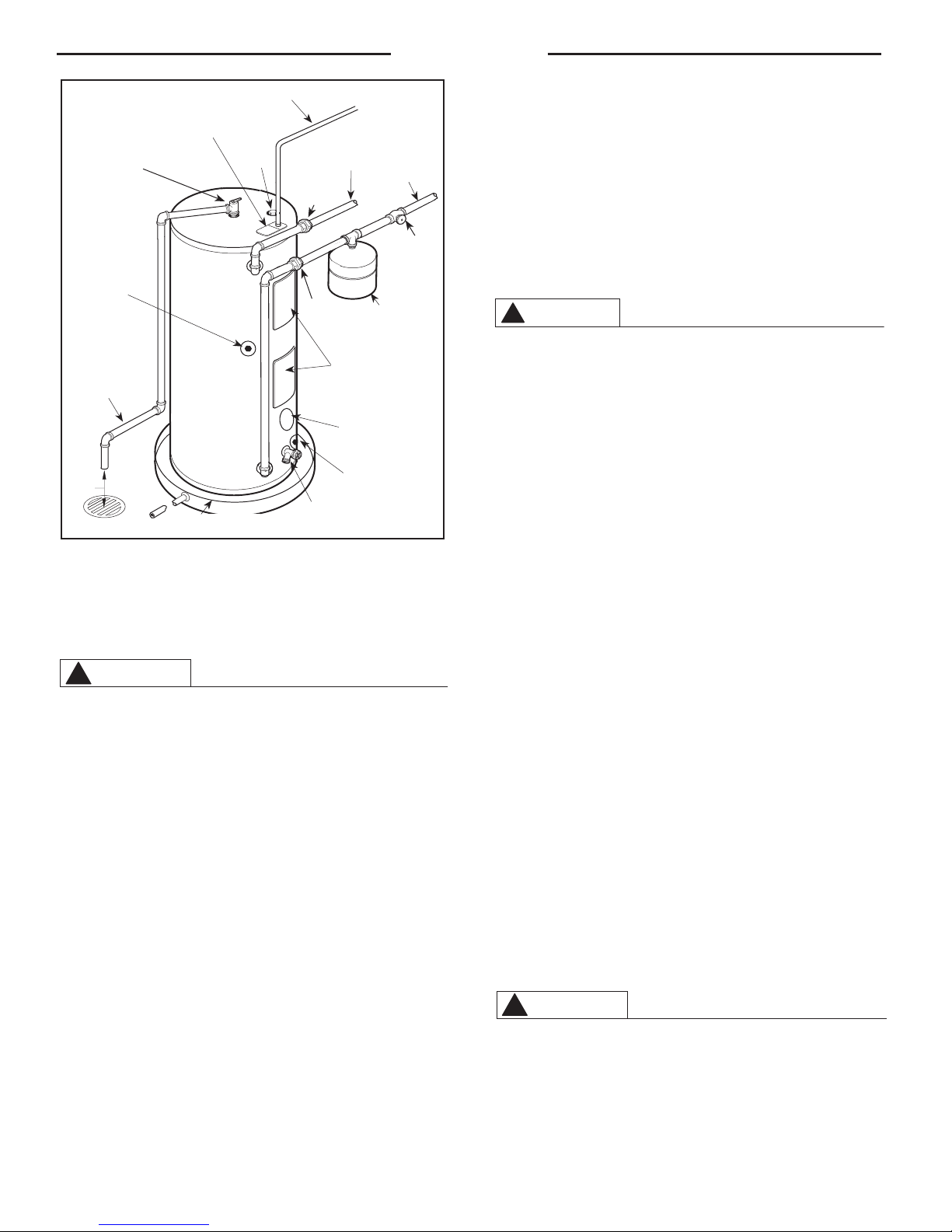
Installation
E
L
I
E
F
V
A
L
V
E
**
Temperature
& Pressure Relief
Valve
*Collector Return
Line Connection
Relief Valve
Discharge Line
to Suitable Open
Drain.
Air Gap
6”
*
These connections are for non-potable heat transfer fluid loop. Do not make potable water
connections to these fittings. Do not introduce non-potable heat transfer fluids into any other
tank fitting.
**
Temperature and Pressure Relief Valve has alternate location on top of heater for 65 Gallon
heaters.
Electrical Junction
Box (Use Copper
Conductors Only)
Auxiliary Catch Pan
To Electrical Distribution Panel
Anode
Hot Water Outlet
to Fixtures
Union
Union
Jacket
Access
Panel
Solar Sensor Access
Cover (Solar Sensor Not
*
System
Drain
Valve
To Cold
Water
Supply
Shut-Off
Valve
Thermal Expansion
Tank (if required)
Provided)
To Solar Collector
Figure 2 - Typical Installation
WARNING
!
Many heat transfer fluids are classified as toxic. Do not
introduce heat transfer fluids into any fitting on the heater
except those clearly marked for that purpose.
Any of the commonly accepted solar heat transfer fluids may
be used in the exchanger, provided they contain appropr iate
corrosion inhibitors for copper systems. Anti-freeze fluids will
turn acidic when exposed to prolonged high temperatures, causing corrosion damage in solar systems. A regular maintenance
schedule must be established to monitor and maintain the proper
pH level of the heat transfer fluid in the system to protect the
heat exchanger and other metallic par ts.
When making connections to the heat exchanger, do not use
standard pipe dope. Use teflon tape, teflon joint compound or
fuorosilicone rubber sealant to prevent anti-freeze leaks. Do not
apply heat to heat exchanger fittings when making sweat connections. Sweat tubing to adapter before fitting to solar connections.
To protect the tank and heat exchanger from damage, the solar
loop must contain a pressure relief valve, and a check valve to
prevent thermosyphoning.
A 1/2” npt fitting is provided on the tank surface (beneath the
plastic snap cap on lower front of jacket) for installation of a solar
control sensor. The solar control should incorporate a recycling
shut-off switch that limits the temperature of the stored water
to 180°F. Also , a mixing valve should be provided to limit water
temperature at fixtures to 140°F. The solar sensor and mixing
valve are not included with the tank. It must be purchas ed
seperately. Please contact the place of purchase for details.
4. POTABLE WATER SUPPLY CONNECTIONS — Refer to Fig.
2 for suggested typical installation. The installation of unions
or flexible copper connectors is recommended on the hot and
cold water connections so that the water heater may be easily
disconnected for servicing if necessar y. The HOT and COLD
water connections are clearly marked and are 3/4” NPT on all
models. Install a shut-off valve in the cold water line near the
water heater.
CAUTION
!
Do not introduce heat transfer fluids into any potable water connection.
IMPORTANT!! Do not apply heat to the hot or cold water connections. If sweat connections are used, sweat tubing to adapter before
fitting adapter to hot or cold water connections on heater. Any heat
applied to the hot or cold water supply fittings will permanently damage them.
5. RELIEF VALVE — A new combination temperature and pressure
relief valve, complying with the Standard for Relief Valves and Automatic Gas Shutoff Devices for Hot Water Supply Systems, ANSI
Z21.22, must be installed in the opening provided and marked
for the purpose on the water heater. (Refer to Fig. 2.) No valve
of any type should be installed between the relief valve and the
tank. Local codes shall gover n the installation of relief valves.
The pressure rating of the relief valve must not exceed 150 PSI,
the maximum working pressure of the water heater as marked
on the rating plate. The Btu/h rating of the relief valve must not be
less than the input rating of the water heater as indicated on the
rating label located on front of the heater (1 watt = 3.412 Btu/h).
Connect the outlet of the relief valve to a suitable open drain
so that the discharge water cannot contact live electrical parts
and to eliminate potential water damage. Piping used should
be of a type approved for hot water distribution. The discharge
line must be no smaller than the outlet of the valve and must
pitch downward from the valve to allow complete drainage (by
gravity) of the relief valve and discharge line. The end of the
discharge line should not be threaded or concealed and should
be protected from freezing. No valve of any type, restriction or
reducer coupling should be installed in the discharge line.
6. TO FILL WATER HEATER — Make cer tain drain valve is completely closed. Open shut-off valve in cold water supply line.
Open each hot water faucet slowly to allow air to vent from the
water heater and piping. A steady flow of water from the hot
water faucet(s) indicates a full water heater.
WARNING
!
Tank MUST BE full of water before power is turned on.
Heating element WlLL BE DAMAGED if energized for
even a short time while tank is dry. The water heater’s
warranty does not cover damage or failure resulting
from operation with an empty or partially empty tank.
(Reference is made to the limited warranty for complete terms and conditions.)
4
Installation
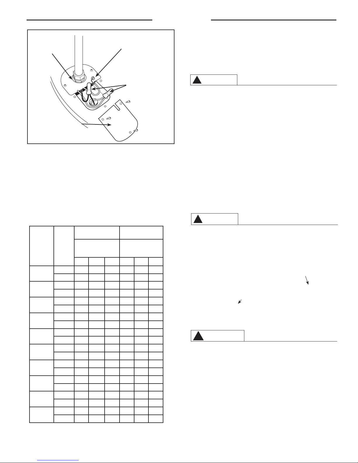
CAUTION
!
Conduit
Connector
Ground Screw
(See Text)
Wire Connectors
WARNING
Junction Box
Figure 3 - Water Heater Junction Box.
7. ELECTRICAL CONNECTIONS for Electric Element Solar Only— A
separate branch circuit with copper conductors, overcurrent protective device and suitable disconnecting means must be provided
by a qualified electrician. All wiring must conform to local codes or
latest edition of the National Electrical Code ANSI/NFPA 70.
The water heater is completely wired to the junction box inside
jacket at top front of water heater. An opening for 1/2" or 3/4”
electrical fitting is provided for field wiring connections. (Refer to
Fig. 3)
Recommended Over
Total
Water
Heater
Wattage
1,500
2,000
2,500
3,000
3,500
4,000
4,500
5,000
5,500
6,000
Table 1-Branch Circuit Sizing and Wire Size Guide
Phase
Based on N.E.C. ANSI / NFPA 70
Current Protection
(Fuse or Circuit
Breaker)
Amperage Rating
120V 208V 240V 120V 208V 240V
1 20 15 15 12 14 14
---- --- --- --- ---
1 25 15 15 10 14 14
--- --- --- --- --- ---
1 30 20 15 10 12 14
--- --- --- --- --- ---
1 35 20 20 8 12 12
--- --- --- --- --- ---
1 --- 25 20 --- 10 12
--- --- --- --- --- ---
1 --- 25 25 --- 10 10
--- --- --- --- --- ---
1 --- 30 25 --- 10 10
--- --- --- --- --- ---
1 --- 35 30 --- 8 10
--- --- --- --- --- ---
1 --- 35 30 --- 8 10
--- --- --- --- --- ---
1 --- 40 35 --- 8 10
--- --- --- --- --- ---
Copper Wire Size -
AWG Based on
N.E.C.
Table 310-16 (75°C.)
The voltage requirements and wattage load for the water heater
is specified on the rating plate on front of heater.
Table 1 recommends minimum branch circuit sizing based on
National Electric Code. Refer to wir ing diagram on back cover
of this manual for field wiring connections.
CAUTION
!
The presence of water in the piping and water heater
does not provide sufficient conduction for a ground.
Non-metallic piping, dielectric unions, flexible connectors etc. can cause the water heater to be electrically isolated.
The branch circuit wiring should include either:
A. Metallic conduit or metallic sheathed cable approved for use
as a grounding conductor and installed with fittings approved
for the purpose.
B. Non-metallic sheathed cable or metallic conduit or metallic
sheathed cable not approved for use as a ground conductor
shall include a separate conductor for grounding. It should
be attached to the ground ter minals of the water heater and
the electrical distribution box. (Refer to Fig. 3)
The manufacturer’s warranty does not cover any
damage or defect caused by installation, attachment
or use of any type of energy sav i ng or oth er
unapproved devices (other than those authorized by
the manufacturer) into, onto or in conjunction with the
water heater. The use of unauthorized energy saving
devices may shorten the life of the water heater and
may endanger life and property. The manufacturer
disclaims any responsibility for such loss or injury
resulting from the use of such unauthorized devices.
If local codes require external application of insulation
blanket kits the manufacturer’s instructions included with
the kit must be carefully followed.
WARNING
!
Application of any external insulation to this water heater
will require careful attention to the following:
• Do Not cover the temperature and pressure relief
valve.
• Do Not cover jacket access panel to thermostat
and heating element.
• Do Not cover electrical junction box of water
heater.
• Do Not cover operating or warning labels at-
tached to the water heater nor attempt to relocate
them on exterior of insulation blanket.
5
 Loading...