

Rheem Residential Electric Models Use & Care Manual
!
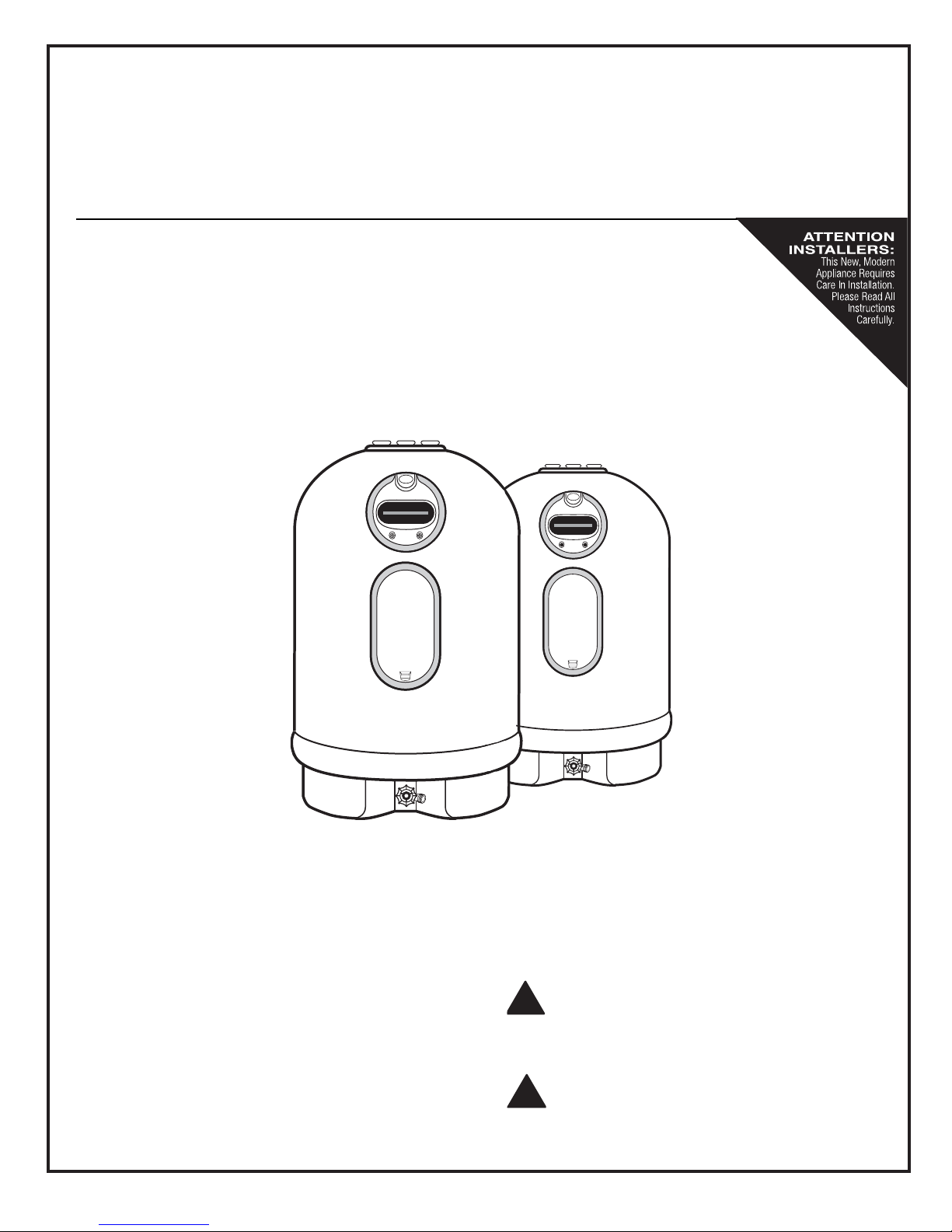
Non-Metallic Electric Water Heater
USE & CARE MANUAL
WITH INSTALLATION INSTRUCTIONS FOR THE INSTALLER
Residential Electric Models
15 - 20 Gallon Point-of-Use
■■■✦■■■
■■■✦■■■
The purpose of this manual is twofold: one, for the installer,
to provide requirements and recommendations for the proper installation and adjustment of the water heater; and two,
for the owner-operator, to explain the features, operation,
safety precautions, maintenance and trouble shooting of
the water heater. This manual also includes a parts list supplement.
It is imperative that all persons who are expected to install,
maintain, operate or adjust this water heater read the
instructions carefully so that they may understand how to
do so.
Recognize this symbol as an Indication of
Important Safety Information!
Do Not Destroy this Manual. Please read
carefully and keep in a safe place for
!
Future Reference.

Table of Contents
General Safety Precautions
Introduction
. . . . . . . . . . . . . . . . . . . . . . . . . . . . . . . . . . . . . . . . . . . . . . . . . . . . . . . . . . . . . . . . . . . . . . . . . . . . . . 2
. . . . . . . . . . . . . . . . . . . . . . . . . . . . . . . . . . . . . . . . . . . . . . . . . . . . . . . . . . . . . . . 1
Installation Instructions
Thermal Expansion . . . . . . . . . . . . . . . . . . . . . . . . . . . . . . . . . . . . . . . . . . . . . . . . . . . . . . . . . . . . . . . . . . . . . . . . 2
Water Supply Connections . . . . . . . . . . . . . . . . . . . . . . . . . . . . . . . . . . . . . . . . . . . . . . . . . . . . . . . . . . . . . . . . . . 4
Temperature and Pressure Relief Valve . . . . . . . . . . . . . . . . . . . . . . . . . . . . . . . . . . . . . . . . . . . . . . . . . . . . . . . 4
Drain Valve . . . . . . . . . . . . . . . . . . . . . . . . . . . . . . . . . . . . . . . . . . . . . . . . . . . . . . . . . . . . . . . . . . . . . . . . . . . . . . . 5
Filling Water Heater . . . . . . . . . . . . . . . . . . . . . . . . . . . . . . . . . . . . . . . . . . . . . . . . . . . . . . . . . . . . . . . . . . . . . . . . 5
Electrical Connections . . . . . . . . . . . . . . . . . . . . . . . . . . . . . . . . . . . . . . . . . . . . . . . . . . . . . . . . . . . . . . . . . . . . . 5
Wiring Diagrams . . . . . . . . . . . . . . . . . . . . . . . . . . . . . . . . . . . . . . . . . . . . . . . . . . . . . . . . . . . . . . . . . . . . . . . . . . 6
Pipe Wrap Energy Kit . . . . . . . . . . . . . . . . . . . . . . . . . . . . . . . . . . . . . . . . . . . . . . . . . . . . . . . . . . . . . . . . . . . . . . 6
Installation Checklist . . . . . . . . . . . . . . . . . . . . . . . . . . . . . . . . . . . . . . . . . . . . . . . . . . . . . . . . . . . . . . . . . . . . . . 7
Operation
Safety Precautions . . . . . . . . . . . . . . . . . . . . . . . . . . . . . . . . . . . . . . . . . . . . . . . . . . . . . . . . . . . . . . . . . . . . . . . . 8
Thermal Performance . . . . . . . . . . . . . . . . . . . . . . . . . . . . . . . . . . . . . . . . . . . . . . . . . . . . . . . . . . . . . . . . . . . . . . 8
Setting the Water Temperature . . . . . . . . . . . . . . . . . . . . . . . . . . . . . . . . . . . . . . . . . . . . . . . . . . . . . . . . . . . . . . 8
Safety Controls . . . . . . . . . . . . . . . . . . . . . . . . . . . . . . . . . . . . . . . . . . . . . . . . . . . . . . . . . . . . . . . . . . . . . . . . . . . 9
Emergency Instructions . . . . . . . . . . . . . . . . . . . . . . . . . . . . . . . . . . . . . . . . . . . . . . . . . . . . . . . . . . . . . . . . . . . . 9
Vacation and Long Time Shut-Down . . . . . . . . . . . . . . . . . . . . . . . . . . . . . . . . . . . . . . . . . . . . . . . . . . . . . . . . . . 9
Draining the Water Heater . . . . . . . . . . . . . . . . . . . . . . . . . . . . . . . . . . . . . . . . . . . . . . . . . . . . . . . . . . . . . . . . . . 10
Maintenance
Routine Preventive Maintenance . . . . . . . . . . . . . . . . . . . . . . . . . . . . . . . . . . . . . . . . . . . . . . . . . . . . . . . . . . . . . 11
Temperature and Pressure Relief Valve . . . . . . . . . . . . . . . . . . . . . . . . . . . . . . . . . . . . . . . . . . . . . . . . . . . . . . . 11
Heating Elements . . . . . . . . . . . . . . . . . . . . . . . . . . . . . . . . . . . . . . . . . . . . . . . . . . . . . . . . . . . . . . . . . . . . . . . . . 12
Trouble Shooting Guide
Wiring Schematic Diagrams
Warranty
Specifications
. . . . . . . . . . . . . . . . . . . . . . . . . . . . . . . . . . . . . . . . . . . . . . . . . . . . . . . . . . . . .See Separate Supplement
. . . . . . . . . . . . . . . . . . . . . . . . . . . . . . . . . . . . . . . . . . . . . . . . . . . . . . . .See Separate Supplement
. . . . . . . . . . . . . . . . . . . . . . . . . . . . . . . . . . . . . . . . . . . . . . . . . . . . . . . . . . . . . . . . . . 13
. . . . . . . . . . . . . . . . . . . . . . . . . . . . . . . . . . . . . . . . . . . . . . . . . . . . . . . . . . . . . . 6
Repair Parts
Abbreviations found in this Instruction Manual
U.L. — Underwriters Laboratories, 333 Pfingsten Rd., Northbrook, IL 60062
National Electrical Code — This publication is available from your local government, public library, electric company, or by writing to U.L.
A.N.S.I. — American National Standards Institute
A.S.M.E. — American Society of Mechanical Engineers.
. . . . . . . . . . . . . . . . . . . . . . . . . . . . . . . . . . . . . . . . . . . . . . . . . . . . . . . . .See Separate Supplement
!
General Safety Precautions
Be sure to read and understand the entire Use & Care Manual before attempting to install or operate this water heater. It may save you time and
cost. Pay particular attention to the General Safety Precautions. Failure to follow these warnings could result in serious bodily injury or death .
Should you have problems understanding the instructions in this manual, or have any questions, STOP, and get help from a qualified installer,
service technician, or the local electric utility.
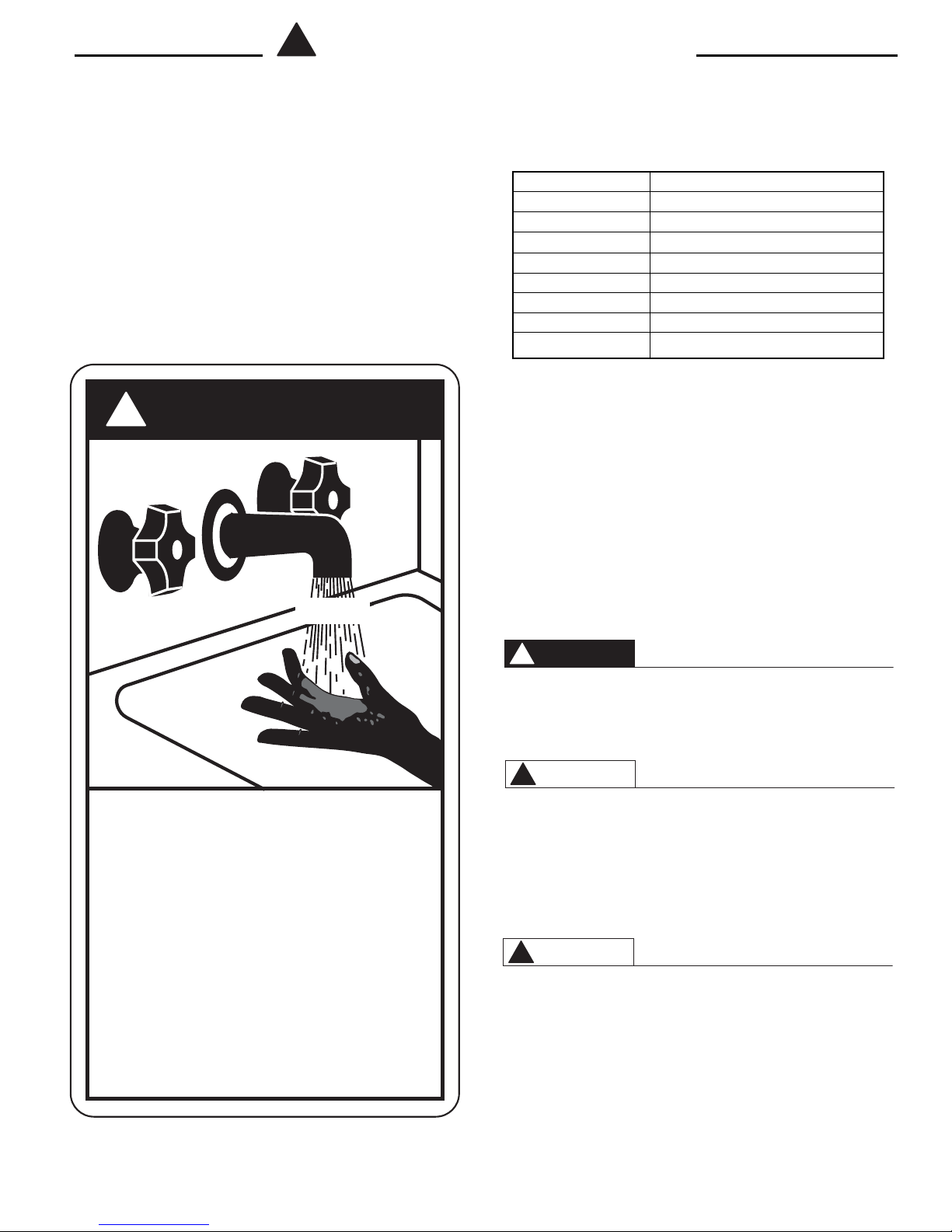
WATER TEMPERATURE ADJUSTMENT - Safety and energy conservation are factors to be considered when selecting the water temperature setting of water heater’s thermostat. Water temperatures above 125°F. can cause
severe burns or death from scalding. Be sure to read and
follow the warnings outlined on the label pictured below.
This label is also located on the water heater near the thermostat access panel
!
DANGER
HOT
TIME / TEMPERATURE RELATIONSHIPS IN SCALDS
Temperature Time to Produce Serious Burn
120° F. More than 5 minutes
1
125° F. 1
130° F. About 30 seconds
135° F. About 10 seconds
140° F. Less than 5 seconds
145° F. Less than 3 seconds
150° F. About 1
155° F. About 1 second
The chart shown above may be used as a guide in determining the proper water temperature for your home.
NOTE: Households with small children, disabled, or elderly
persons may require a 120°F. or lower thermostat setting to
prevent contact with “HOT” water.
The temperature of the water in the heater is regulated by
the adjustable surface mounted thermostat(s) located
behind the Jacket Access Panel(s). Dual element heaters
have two thermostats. To comply with safety regulations
the thermostat(s) were set at 120° F. before the water
heater was shipped from the factory.
There is a Hot Water SCALD Potential if the thermostat is
set too high.
/2to 2 minutes
1
/2seconds
Table courtesy of Shriners Burn Institute
BURN
Water temperature over 125°F can
cause severe burns instantly or
death from scalds.
Children, disabled and elderly are
at highest risk of being scalded.
See instruction manual before
setting temperature at water
heater.
Feel water before bathing or
showering.
Temperature limiting valves are
available, see manual.
DANGER
!
Mixing valves for reducing point of use water temperature
by mixing hot and cold water in branch water lines are
available. Contact a licensed plumber or the local plumbing
authority for further information.
WARNING
!
After installing, do not turn on or operate the water heater
unless the temperature and pressure relief is in place and
operating properly, you have properly installed the drain
pipe on the temperature and pressure relief valve, the vacu-
um relief valve has been installed, and you have complete-
ly filed the water heater with water.
WARNING
!
HAZARD OF ELECTRICAL SHOCK! Before removing any
access panels or servicing the water heater, make sure the
electrical supply to the water heater is turned ”OFF”. Fail-
ure to do this could result in property damage, bodily injury
or death.
1
Introduction
Thank you for buying your non-metallic electric water heater. Your new water
heater is made of the latest materials and will not rust or corrode. It will give
many years of hot water service when installed, operated and maintained
according to the instructions in this manual.
Your water heater is completely assembled and ready to install. This manual
provides the general instructions for installation. Because of several variables,
such as the installation location, existing piping, and local codes, it is impossible to provide exact instructions for everyone’s specific needs. For this reason,
it is suggested that the entire manual be read prior to beginning any installation
work, then carefully plan the installation. This can help to avoid costly mistakes
including damage to the water heater, not covered under terms of the warranty.
Almost all new products (automobiles, boats, clothing, plastic and wood items,
etc.) have an odor or smell to them for a time. This water heater may also have
a ”new” smell or odor to it due to the non-metallic materials used in the manufacturing process. This ”new” smell is not harmful, and will disappear in a short
time.
The vacuum valve, which must be used when installing the water heater, is
factory installed.
The location chosen for the water heater must take into consideration the following:
LOCAL INSTALLATION REGULATIONS
This water heater must be installed in accordance with these instructions,
local codes, utility company requirements or, in the absence of local codes,
the latest edition of the National Electrical Code. It is available from some local
libraries or can be purchased from the National Fire Prevention Association,
Batterymarch Park, Quincy, MA 02269 as booklet ANSI/NFPA 70.
LOCATION
Locate the water heater in a clean dry area as near as practical to the area of
greatest heated water demand. Long uninsulated hot water lines can waste
energy and water. Place the water heater in such a manner that the thermostat
and element access panels can be removed to permit inspection and servicing
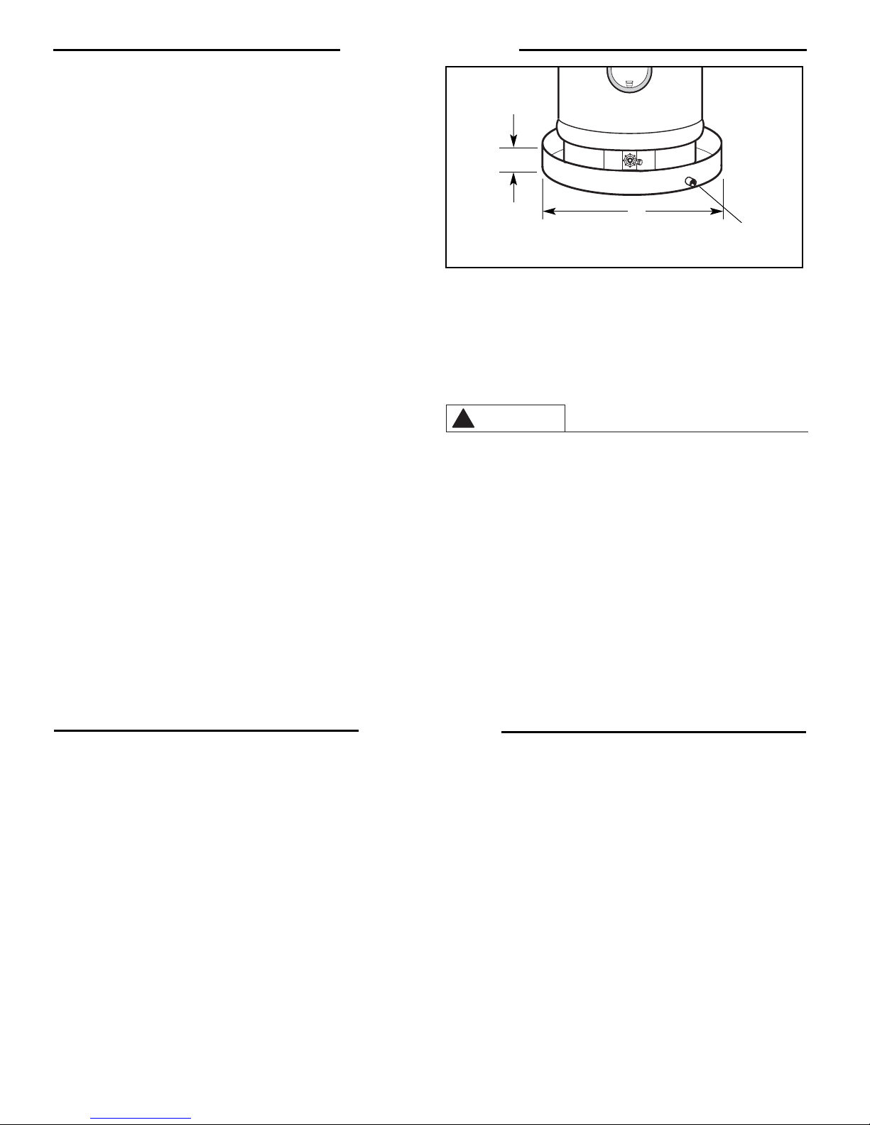
A — Diameter of water heater plus 2" min.
B — Maximum 2"
Figure 1. — Auxiliary Drain Pan
such as removal of elements or checking controls. The water heater and water
lines should be protected from freezing temperatures. Do not install the water
heater in outdoor, unprotected areas, or near any other appliances where high
temperature are present, such as wood burning stoves, boilers or furnaces.
High temperatures can warp or otherwise damage the non-metallic construction of this water heater.
CAUTION
!
The water heater should not be located in an area where leakage of
the tank or connections will result in damage to the area adjacent
to it or to lower floors of the structure. Where such areas cannot be
avoided, it is recommended that a suitable drain pan, adequately
drained, be installed under the water heater.
NOTE: Auxiliary drain pan installation MUST conform to local
codes.
Drain Pan Kits are available at your local retail outlet or service center.
B
A
To open drain, line should
be at least
pitched for proper drainage.
3
/4" ID and
1. INSPECT SHIPMENT — Inspect water heater for possible damage.
Check the markings on the rating plate of the water heater to be certain the
power supply corresponds to that for which the water heater is equipped.
2. THERMAL EXPANSION — Determine if a check valve exists in the
inlet water line. It may have been installed in the cold water line as a
separate back flow preventer, or it may be part of a pressure reducing
valve, water meter or water softener. A check valve located in the cold
water inlet line can cause what is referred to as a ”closed water sys-
tem”. A cold water inlet line with no check valve or back flow prevention
device is referred to as an ”open” water system.
As water is heated, it expands in volume and creates an increase
in the pressure within the water system. This action is referred to
as ”thermal expansion”. In an ”open” water system, expanding
water which exceeds the capacity of the water heater flows back
into the city main where the pressure is easily dissipated.
A ”closed water system”, however, prevents the expanding
water from flowing back into the main supply line, and the result
Installation
of ”thermal expansion” can create a rapid, and dangerous pres-
sure increase in the water heater and system piping. This rapid
pressure increase can quickly reach the safety setting of the relief valve, causing it to operate during each heating cycle. Thermal expansion, and the resulting rapid, and repeated expansion
and contraction of components in the water heater and piping
system can cause premature failure of the relief valve, and possibly the heater itself. Replacing the relief valve will not correct
the problem!
The suggested method of controlling thermal expansion is to install
an expansion tank in the cold water line between the water heater
and the check valve. The expansion tank is designed with an air cushion built in that compresses as the system pressure increases,
thereby relieving the over pressure condition and eliminating the repeated operation of the relief valve. Other methods of controlling thermal expansion are also available. Contact your installing contractor,
water supplier, or plumbing inspector for additional information regarding this subject.
2
Installation
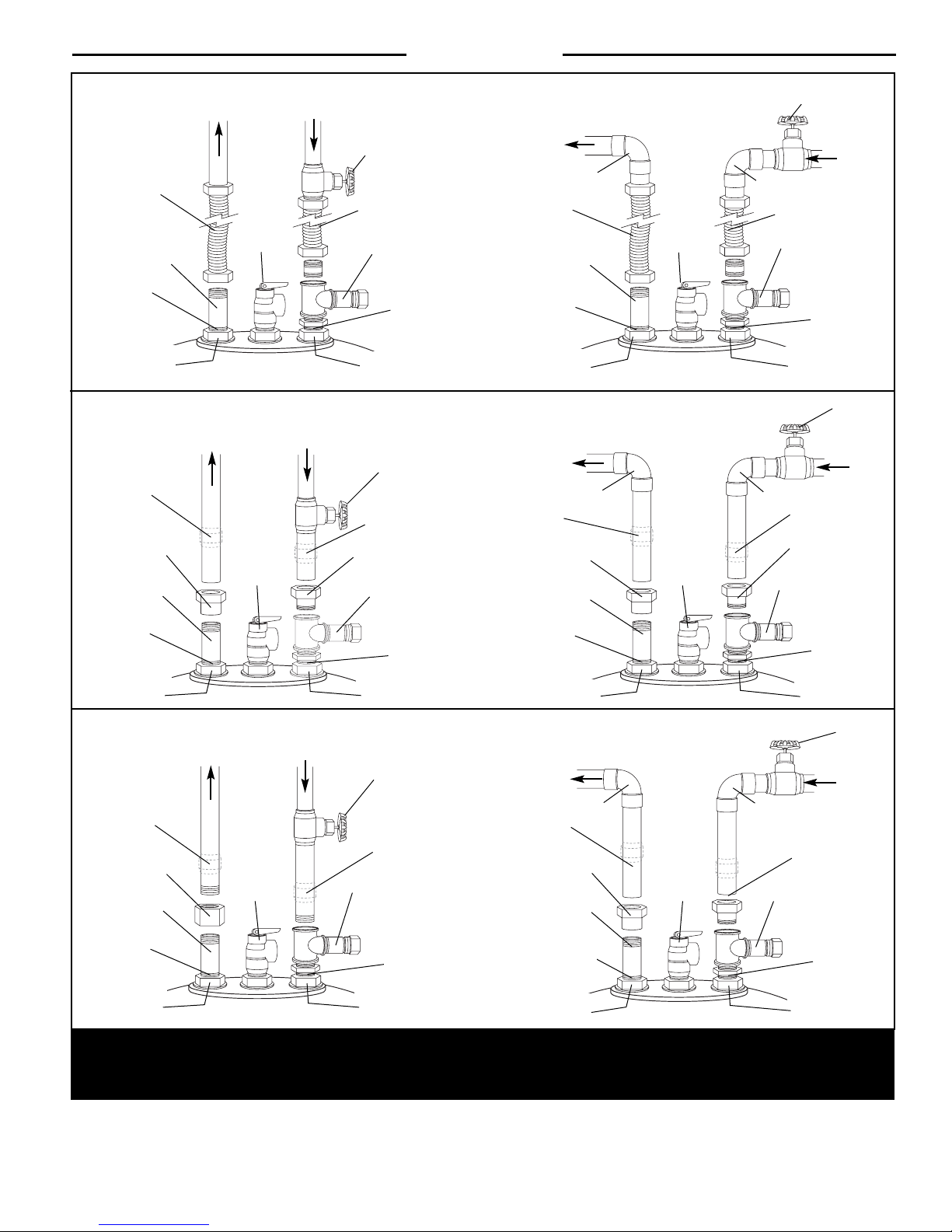
CAUTION: DO NOT SWEAT SOLDER DIRECTLY TO THE WATER HEATER HEX UNION NUTS AS SOLDERING
TORCH HEAT WILL DAMAGE THE WATER HEA
TER BEYOND REPAIR.
Flexible
Connector
Extension Fitting
(included with heater)
Seal Ring
(included with heater)
HOT Outlet
Hex Union Nut
Union
3/4” Adaptor
Sweat X Female Pipe
Extension Fitting
(included with heater)
Seal Ring
(included with heater)
HOT Outlet
Hex Union Nut
Hot Water
Outlet
Hot Water
Outlet
T & P
Relief
Valve
T & P
Relief
Valve
Cold Water
*
Cold Water
*
Inlet
Inlet
WATER HEATER
INSTALLATION KIT
Shut-Off
Valve
Flexible
Connector
Vacuum Valve Ass’y
(included with heater)
Seal Ring
(included with heater)
COLD Inlet
Hex Union Nut
Extension Fitting
(included with heater)
(included with heater)
SOLDERED COPPER OR
CPVC PLASTIC PIPE
Shut-Off
Valve
Union
3/4” Adaptor
Sweat x Male Pipe
Vacuum Valve Ass’y
(included with heater)
Seal Ring
(included with heater)
COLD Inlet
Hex Union Nut
Sweat X Female Pipe
(included with heater)
(included with heater)
Hot Water
Outlet
90° Elbow
Flexible
Connector
Seal Ring
HOT Outlet
Hex Union Nut
Hot Water
Outlet
90° Elbow
Union
3/4” Adaptor
Extension Fitting
Seal Ring
HOT Outlet
Hex Union Nut
T & P
Relief
Valve
T & P
Relief
Valve
Shut-Off
Valve
Cold Water
Inlet
90° Elbow
Flexible
Connector
*
*
Vacuum Valve Ass’y
(included with heater)
Seal Ring
(included with heater)
COLD Inlet
Hex Union Nut
90° Elbow
Union
3/4” Adaptor
Sweat x Male Pipe
Vacuum Valve Ass’y
(included with heater)
Seal Ring
(included with heater)
COLD Inlet
Hex Union Nut
Shut-Off
Valve
Cold Water
Inlet
T & P
Relief
Valve
Cold Water
*
Inlet
Union
3/4” Female Coupling
Extension Fitting
(included with heater)
Seal Ring
(included with heater)
HOT Outlet
Hex Union Nut
Hot Water
Outlet
* See Temperature & Pressure (T & P) Relief Valve section for drain pipe installation details.
Figure 2 — Typical installation methods using Water Heater Installation Kit (top), Soldered Copper or CPVC Pipe (center), or Threaded Pipe
(bottom).
THREADED PIPE
Shut-Off
Valve
Union
Vacuum Valve Ass’y
(included with heater)
Seal Ring
(included with heater)
COLD Inlet
Hex Union Nut
Hot Water
Outlet
3/4” Female Coupling
Extension Fitting
(included with heater)
(included with heater)
Hex Union Nut
3
90° Elbow
Union
Seal Ring
HOT Outlet
T & P
Relief
Valve
Shut-Off
Valve
Cold Water
Inlet
90° Elbow
Union
*
Vacuum Valve Ass’y
(included with heater)
Seal Ring
(included with heater)
COLD Inlet
Hex Union Nut
 Loading...