

Rheem RBHP-21J06SH2, RBHP-17J07SH1, RBHP-17J11SH1, RBHP-17J06SH1, RBHP-21A00NH2 Installation Instructions Manual
...Page 1
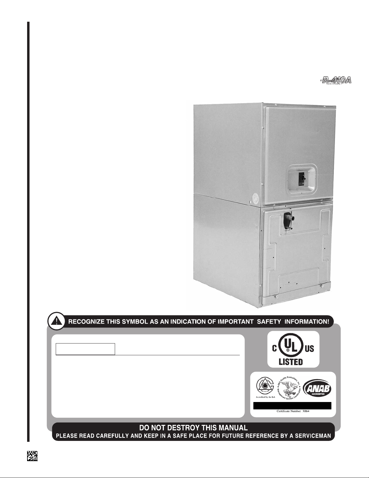
INSTALLATION INSTRUCTIONS
WARNING
ISO 9001:2008
AIR HANDLERS
(-)BHP
• MODELS FEATURING R-22 REFRIGERANT
• MODELS FEATURING EARTH-FRIENDLY R-410A REFRIGERANT
• MODELS FEATURING ELECTRIC HEAT WITHOUT INDOOR
COOLING COIL
!
▲WARNING
These instructions are intended as an aid to qualified licensed
service personnel for proper installation, adjustment and
operation of this unit. Read these instructions thoroughly before
attempting installation or operation. Failure to follow these
instructions may result in improper installation, adjustment,
service or maintenance possibly resulting in fire, electrical
shock, property damage, personal injury or death.
SUPERSEDES 92-20521-44-05
92-20521-44-06
Page 2

TABLE OF CONTENTS
1.0 SAFETY INFORMATION . . . . . . . . . . . . . . . . . . . . . . . . . . . . . . . . . . . . . . . . . . . . 3
2.0 GENERAL INFORMATION . . . . . . . . . . . . . . . . . . . . . . . . . . . . . . . . . . . . . . . . . . 7
2.1 Important Information About Efficiency and Indoor Air Quality. . . . . . . . . . . . 7
2.2 Receiving. . . . . . . . . . . . . . . . . . . . . . . . . . . . . . . . . . . . . . . . . . . . . . . . . . . . 8
2.3 Clearances. . . . . . . . . . . . . . . . . . . . . . . . . . . . . . . . . . . . . . . . . . . . . . . . . . . 8
2.4 Model Number Explanation . . . . . . . . . . . . . . . . . . . . . . . . . . . . . . . . . . . . . . 9
2.5 Dimensions and Weights. . . . . . . . . . . . . . . . . . . . . . . . . . . . . . . . . . . . . . . 10
2.6 Unit Configuration . . . . . . . . . . . . . . . . . . . . . . . . . . . . . . . . . . . . . . . . . . . . . . . . . 11
2.7 Vertical Upflow. . . . . . . . . . . . . . . . . . . . . . . . . . . . . . . . . . . . . . . . . . . . . . . 12
2.8 Vertical Downflow. . . . . . . . . . . . . . . . . . . . . . . . . . . . . . . . . . . . . . . . . . . . . 12
2.9 Horizontal. . . . . . . . . . . . . . . . . . . . . . . . . . . . . . . . . . . . . . . . . . . . . . . . . . . 14
3.0 ELECTRICAL WIRING. . . . . . . . . . . . . . . . . . . . . . . . . . . . . . . . . . . . . . . . . . . . . 15
3.1 Power Wiring . . . . . . . . . . . . . . . . . . . . . . . . . . . . . . . . . . . . . . . . . . . . . . . . 15
3.2 Control Wiring . . . . . . . . . . . . . . . . . . . . . . . . . . . . . . . . . . . . . . . . . . . . . . . 16
3.3 Grounding . . . . . . . . . . . . . . . . . . . . . . . . . . . . . . . . . . . . . . . . . . . . . . . . . . 16
3.4 Blower Motor Electrical Data: “A” Voltage . . . . . . . . . . . . . . . . . . . . . . . . . . 17
3.5 Blower Motor Electrical Data: “J” Voltage . . . . . . . . . . . . . . . . . . . . . . . . . . 17
3.6 Electric Heat Electrical Data . . . . . . . . . . . . . . . . . . . . . . . . . . . . . . . . . . . . 17
4.0 DUCTWORK. . . . . . . . . . . . . . . . . . . . . . . . . . . . . . . . . . . . . . . . . . . . . . . . . . . . . 19
5.0 REFRIGERANT CONNECTIONS . . . . . . . . . . . . . . . . . . . . . . . . . . . . . . . . . . . . 20
5.1 Flowcheck Pistons. . . . . . . . . . . . . . . . . . . . . . . . . . . . . . . . . . . . . . . . . . . . 20
6.0 CONDENSATE DRAIN TUBING . . . . . . . . . . . . . . . . . . . . . . . . . . . . . . . . . . . . . 21
7.0 AIR FILTER . . . . . . . . . . . . . . . . . . . . . . . . . . . . . . . . . . . . . . . . . . . . . . . . . . . . . 22
8.0 AIRFLOW PERFORMANCE . . . . . . . . . . . . . . . . . . . . . . . . . . . . . . . . . . . . . . . . 22
8.1 Airflow Operatng Limits . . . . . . . . . . . . . . . . . . . . . . . . . . . . . . . . . . . . . . . . 23
8.2 Airflow Performance Data . . . . . . . . . . . . . . . . . . . . . . . . . . . . . . . . . . . . . . 23
9.0 SEQUENCE OF OPERATION . . . . . . . . . . . . . . . . . . . . . . . . . . . . . . . . . . . . . . . 25
9.1 Cooling (cooling only or heat pump) . . . . . . . . . . . . . . . . . . . . . . . . . . . . . . 25
9.2 Heating (electric heat only) . . . . . . . . . . . . . . . . . . . . . . . . . . . . . . . . . . . . . 25
9.3 Heating (heat pump) . . . . . . . . . . . . . . . . . . . . . . . . . . . . . . . . . . . . . . . . . . 25
9.4 Watt Restrictor. . . . . . . . . . . . . . . . . . . . . . . . . . . . . . . . . . . . . . . . . . . . . . . 25
9.5 Defrost Sequence . . . . . . . . . . . . . . . . . . . . . . . . . . . . . . . . . . . . . . . . . . . . 25
9.6 Emergency Heat (Heating of Heat Pump) . . . . . . . . . . . . . . . . . . . . . . . . . . 26
9.7 Room Thermostat (Anticipator Setting) . . . . . . . . . . . . . . . . . . . . . . . . . . . . 26
10.0 CALCULATIONS . . . . . . . . . . . . . . . . . . . . . . . . . . . . . . . . . . . . . . . . . . . . . . . . . 26
10.1 Calculating Temperature Rise . . . . . . . . . . . . . . . . . . . . . . . . . . . . . . . . . . . 26
10.2 Calculating BTUH Heating Capacity . . . . . . . . . . . . . . . . . . . . . . . . . . . . . . 26
10.3 Calculating Airflow CFM. . . . . . . . . . . . . . . . . . . . . . . . . . . . . . . . . . . . . . . . 26
10.4 Calculating Correction Factor . . . . . . . . . . . . . . . . . . . . . . . . . . . . . . . . . . . 26
11.0 PRE-START CHECKLIST . . . . . . . . . . . . . . . . . . . . . . . . . . . . . . . . . . . . . . . . . . 27
12.0 MAINTENANCE . . . . . . . . . . . . . . . . . . . . . . . . . . . . . . . . . . . . . . . . . . . . . . . . . . 27
12.1 Air Filter . . . . . . . . . . . . . . . . . . . . . . . . . . . . . . . . . . . . . . . . . . . . . . . . . . . . 27
12.2 Indoor Coil-Drain Pan-Drain Line. . . . . . . . . . . . . . . . . . . . . . . . . . . . . . . . . 28
12.3 Blower Motor and Wheel . . . . . . . . . . . . . . . . . . . . . . . . . . . . . . . . . . . . . . . 28
12.4 Lubrication . . . . . . . . . . . . . . . . . . . . . . . . . . . . . . . . . . . . . . . . . . . . . . . . . . 28
12.5 Blower Assembly Removal and Replacement. . . . . . . . . . . . . . . . . . . . . . . 28
12.6 Electric Heater Replacement . . . . . . . . . . . . . . . . . . . . . . . . . . . . . . . . . . . . 29
12.7 Motor Replacement . . . . . . . . . . . . . . . . . . . . . . . . . . . . . . . . . . . . . . . . . . . 29
13.0 REPLACEMENT PARTS . . . . . . . . . . . . . . . . . . . . . . . . . . . . . . . . . . . . . . . . . . . 30
14.0 ACCESSORIES - KITS - PARTS . . . . . . . . . . . . . . . . . . . . . . . . . . . . . . . . . . . . . 31
2
Page 3
1.0 SAFETY INFORMATION
Improper installation, or installation not made in accordance with the Underwriters
Laboratory certification or these instructions, can result in unsatisfactory operation
and/or dangerous conditions and are not covered by the unit warranty.
WARNING
!
Duct leaks can create an unbalanced system and draw pollutants such as dirt,
dust, fumes and odors into the home causing property damage. Fumes and
odors from toxic, volatile or flammable chemicals, as well as automobile
exhaust and carbon monoxide (CO), can be drawn into the living space
through leaking ducts and unbalanced duct systems causing personal injury
or death (see Figure 1).
• If air-moving equipment or ductwork is located in garages or off-garage storage areas - all joints, seams, and openings in the equipment and duct must
be sealed to limit the migration of toxic fumes and odors including carbon
monoxide from migrating into the living space.
• If air-moving equipment or ductwork is located in spaces containing fuel
burning appliances such as water heaters or boilers - all joints, seams, and
openings in the equipment and duct must also be sealed to prevent depressurization of the space and possible migration of combustion byproducts
including carbon monoxide into the living space.
WARNING
!
THESE INSTRUCTIONS ARE INTENDED AS AN AID TO QUALIFIED, LICENSED
SERVICE PERSONNEL FOR PROPER INSTALLATION, SET UP AND OPERATION OF THIS UNIT. READ THESE INSTRUCTIONS THOROUGHLY BEFORE
ATTEMPTING INSTALLATION OR OPERATION. FAILURE TO FOLLOW THESE
INSTRUCTIONS MAY RESULT IN IMPROPER INSTALLATION, SET UP, SERVICE
OR MAINTENANCE POSSIBLY RESULTING IN FIRE, ELECTRICAL SHOCK,
PROPERTY DAMAGE, PERSONAL INJURY OR DEATH.
WARNING
!
PROPOSITION 65: THIS APPLIANCE CONTAINS FIBERGLASS INSULATION. RESPIRABLE PARTI CLES OF FIBERGLASS ARE KNOWN TO THE STATE OF CALIFORNIA TO CAUSE CANCER.
WARNING
!
DO NOT, UNDER ANY CIRCUMSTANCES, CONNECT RETURN DUCTWORK TO
ANY OTHER HEAT PRODUCING DEVICE SUCH AS FIREPLACE INSERT,
STOVE, ETC. UNAUTHORIZED USE OF SUCH DEVICES MAY RESULT IN FIRE,
CARBON MONOXIDE POISONING, EXPLOSION, PERSONAL INJURY OR PROPERTY DAMAGE.
CAUTION
!
When installing a unit with cooling coil over a finished ceiling and/or living
space, installation of an auxiliary drain pan under the entire unit, to avoid damage to ceiling, is recommended.
WARNING
!
DISCONNECT ALL POWER TO UNIT BEFORE INSTALLING OR SERVICING.
MORE THAN ONE DISCONNECT SWITCH MAY BE REQUIRED TO DE-ENERGIZE THE EQUIPMENT. HAZARDOUS VOLTAGE CAN CAUSE SEVERE PERSONAL INJURY OR DEATH.
WARNING
!
BECAUSE OF POSSIBLE DAMAGE TO EQUIPMENT OR PERSONAL INJURY,
INSTALLATION, SERVICE AND MAINTENANCE SHOULD BE PERFORMED BY
A TRAINED, QUALIFIED SERVICE PERSON. CONSUMER SERVICE IS RECOMMENDED ONLY FOR FILTER CLEANING/ REPLACEMENT. NEVER OPERATE
THE UNIT WITH THE ACCESS PANELS REMOVED.
3
Page 4
WARNING
!
DO NOT INSTALL THIS UNIT IN MANUFACTURED (MOBILE) HOMES.
IMPROPER INSTALLATION IS MORE LIKELY IN MANUFACTURED HOUSING
DUE TO DUCTWORK MATERIAL, SIZE, LOCATION, AND ARRANGEMENT.
INSTALLATIONS IN MANUFACTURED HOUSING CAN CAUSE A FIRE RESULTING IN PROPERTY DAMAGE, PERSONAL INJURY OR DEATH.
EXCEPTION: MANUFACTURED HOUSING INSTALLATIONS ARE APPROVED
ONLY WITH DOCUMENTATION BY A RECOGNIZED INSPECTION AUTHORITY
THAT THE INSTALLATION HAS BEEN MADE IN COMPLIANCE WITH THE
INSTRUCTIONS AND ALL WARNINGS HAVE BEEN OBSERVED.
WARNING
!
IF UNIT IS TO BE INSTALLED WITHOUT AN INDOOR COIL, RETURN DUCT OR
PLENUM, IT MUST NOT BE IN STALLED DIRECTLY OVER COMBUSTIBLE MATERIAL. IF INSTALLED WITHOUT AN INDOOR COIL WITH A RETURN DUCT OR
PLENUM, THE AIR PLENUM OR DUCT MUST HAVE A SOLID SHEET METAL
BOTTOM WITH NO RETURN AIR OPENINGS, REGISTERS OR FLEXIBLE AIR
DUCTS LOCATED DIRECTLY UNDER THE UNIT. EXPOSING COMBUSTIBLE
MATERIAL TO THE RETURN OPENING OF AN UPFLOW UNIT WITHOUT AN
INDOOR COIL CAN CAUSE A FIRE RESULTING IN PROPERTY DAMAGE, PERSONAL INJURY OR DEATH.
WARNING
!
THE RXBB-AA COMBUSTIBLE FLOOR BASE IS REQUIRED WHEN SOME
UNITS WITH ELECTRIC HEAT ARE APPLIED DOWNFLOW ON COMBUSTIBLE
FLOORING. FAILURE TO USE THE BASE CAN CAUSE A FIRE RESULTING IN
PROPERTY DAMAGE, PERSONAL INJURY OR DEATH. SEE CLEARANCES
FOR UNITS REQUIRING A COMBUSTIBLE FLOOR BASE.
(SEE WARNINGS IN REGARD TO DUCTWORK)
WARNING
!
THE FIRST 36 INCHES OF SUPPLY AIR PLENUM AND DUCTWORK MUST BE
CONSTRUCTED OF SHEET METAL AS REQUIRED BY NFPA 90B. THE SUPPLY
AIR PLENUM OR DUCT MUST HAVE A SOLID SHEET METAL BOTTOM
DIRECTLY UNDER THE UNIT WITH NO OPENINGS, REGISTERS OR FLEXIBLE
AIR DUCTS LOCATED IN IT. IF FLEXIBLE SUPPLY AIR DUCTS ARE USED THEY
MAY BE LOCATED ONLY IN THE VERTICAL WALLS, OF A RECTANGULAR
PLENUM, A MINIMUM OF 6 INCHES FROM THE SOLID BOTTOM. METAL
PLENUM OR DUCT MAY BE CONNECTED TO THE COMBUSTIBLE FLOOR
BASE, IF NOT, IT MUST BE CONNECTED TO THE UNIT SUPPLY DUCT
FLANGES SUCH THAT COMBUSTIBLE FLOOR OR OTHER COMBUSTIBLE
MATERIAL IS NOT EXPOSED TO THE SUPPLY AIR OPENING FROM THE
DOWNFLOW UNIT. EXPOSING COMBUSTIBLE (NON-METAL) MATERIAL TO
THE SUPPLY OPENING OF A DOWNFLOW UNIT CAN CAUSE A FIRE RESULTING IN PROPERTY DAMAGE, PERSONAL INJURY OR DEATH.
EXCEPTIONS TO DOWNFLOW WARNINGS:
• INSTALLATIONS ON CONCRETE FLOOR SLAB WITH SUPPLY AIR PLENUM
AND DUCTWORK COMPLETELY ENCASED IN NOT LESS THAN 2 INCHES OF
CONCRETE (SEE NFPA 90B).
• INSTALLATIONS OF UNITS WITHOUT ELECTRIC HEATERS.
WARNING
!
THE SUPPLY AIR PLENUM OR DUCT MUST HAVE A SOLID SHEET METAL
BOTTOM WITH NO SUPPLY AIR OPENINGS, REGISTERS OR FLEXIBLE AIR
DUCTS LOCATED IN IT FOR THE FIRST 36 INCHES OF HORIZONTAL SURFACE
ON UNITS WITH ELECTRIC HEATERS. FAILURE TO OBSERVE SUPPLY
PLENUM, DUCT WARNINGS CAN CAUSE A FIRE RESULTING IN PROPERTY
DAMAGE, PERSONAL INJURY OR DEATH.
4
Page 5
WARNING
!
THE UNIT MUST BE PERMANENTLY GROUNDED. FAILURE TO DO SO CAN
RESULT IN ELECTRICAL SHOCK CAUSING PERSONAL INJURY OR DEATH.
WARNING
!
UNITS ARE FOR DUCTED APPLICATIONS ONLY. A MINIMUM OF 36 INCHES OF
SUPPLY AIR PLENUM AND DUCTWORK IS REQUIRED. NO SUPPLY AIR OPENINGS, REGISTERS OR FLEXIBLE AIR DUCTS MAY BE LOCATED WITHIN THE
FIRST 36 INCHES OF SUPPLY PLENUM AND DUCTWORK ON UNITS WITH
ELECTRIC HEATERS. FAILURE TO OBSERVE SUPPLY PLENUM/DUCT WARNINGS CAN CAUSE A FIRE RESULTING IN PROPERTY DAMAGE, PERSONAL
INJURY OR DEATH.
WARNING
!
UNITS WITH CIRCUIT BREAKER(S) MEET REQUIREMENTS AS A SERVICE
DISCONNECT SWITCH, HOWEVER, IF ACCESS IS REQUIRED TO THE LINE
SIDE (COVERED) OF THE CIRCUIT BREAKER, THIS SIDE OF THE BREAKER(S)
WILL BE ENERGIZED WITH THE BREAKER(S) DE-ENERGIZED. CONTACT WITH
THE LINE SIDE CAN CAUSE ELECTRICAL SHOCK RESULTING IN PERSONAL
INJURY OR DEATH.
WARNING
!
IF REMOVAL OF THE BLOWER ASSEMBLY IS REQUIRED, ALL DISCONNECT
SWITCHES SUPPLYING POWER TO THE AIRHANDLER MUST BE DE-ENERGIZED AND LOCKED (IF NOT IN SIGHT OF UNIT) SO THE FIELD POWER
WIRES CAN BE SAFELY REMOVED FROM THE BLOWER ASSEMBLY. FAILURE
TO DO SO CAN CAUSE ELECTRICAL SHOCK RESULTING IN PERSONAL
INJURY OR DEATH.
(SEE SPECIFIC AIRFLOW POSITION FOR ADDITIONAL
WARNINGS)
5
Page 6
CAUTION
!
When used on cooling applications, excessive sweating may occur when unit
is installed in an unconditioned space. This can result in property damage.
• Some building codes require extra cabinet insulation and gasketing when
unit is installed in attic applications.
• If installed in an unconditioned space, apply caulking around the power
wires, control wires, refrigerant tubing and condensate line where they enter
the cabinet. Seal the power wires on the inside where they exit conduit
opening. Caulking is required to prevent air leakage into and condensate
from forming inside the unit, control box, and on electrical controls.
• Install the unit in such a way as to allow free access to the coil/filter compartment and blower/control compartment.
• Install the unit in a level position to ensure proper condensate drainage.
Make sure unit is level in both directions within 1/8”.
• Install the unit in accordance with any local code which may apply and the
national codes. Latest editions are available from: “National Fire Protection
Association, Inc., Batterysmarch Park, Quincy, MA 02269.” These publications
are:
• ANSI/NFPA No. 70-(Latest Edition) National Electrical Code.
• NFPA90A Installation of Air Conditioning and Ventilating Systems.
• NFPA90B Installation of warm air heating and air conditioning systems.
• The equipment has been evaluated in accordance with the Code of Federal
Regulations, Chapter XX, Part 3280.
CAUTION
!
HORIZONTAL UNITS MUST BE CONFIGURED FOR RIGHT HAND AIR SUPPLY
OR LEFT HAND AIR SUPPLY. HORIZONTAL DRAIN PAN MUST BE LOCATED
UNDER INDOOR COIL. FAILURE TO USE THE DRAIN PAN CAN RESULT IN
PROPERTY DAMAGE.
NOTICE
!
Improper installation, or installation not made in accordance with the
Underwriters Laboratory (UL) certification or these instructions, can result
in unsatisfactory operation and/or dangerous conditions and are not covered by the unit warranty.
NOTICE
!
In compliance with recognized codes, it is recommended that an auxiliary
drain pan be installed under all evaporator coils or units containing evaporator coils that are located in any area of a structure where damage to the
building or building contents may occur as a result of an overflow of the
coil drain pan or a stoppage in the primary condensate drain piping. See
accessories section of these instructions for auxiliary horizontal overflow
pan information (model RXBM).
6
Page 7
2.0 GENERAL INFORMATION
2.1 IMPORTANT INFORMATION ABOUT EFFICIENCY AND INDOOR
2.1 AIR QUALITY
Central cooling and heating equipment is only as efficient as the duct system that carries the cooled or heated air. To maintain efficiency, comfort and good indoor air quality,
it is important to have the proper balance between the air being supplied to each room
and the air returning to the cooling and heating equipment.
Proper balance and sealing of the duct system improves the efficiency of the heating
and air conditioning system and improves the indoor air quality of the home by reducing
the amount of airborne pollutants that enter homes from spaces where the ductwork and
/ or equipment is located. The manufacturer and the U.S. Environmental Protection
Agency’s Energy Star Program recommend that central duct systems be checked by a
qualified contractor for proper balance and sealing.
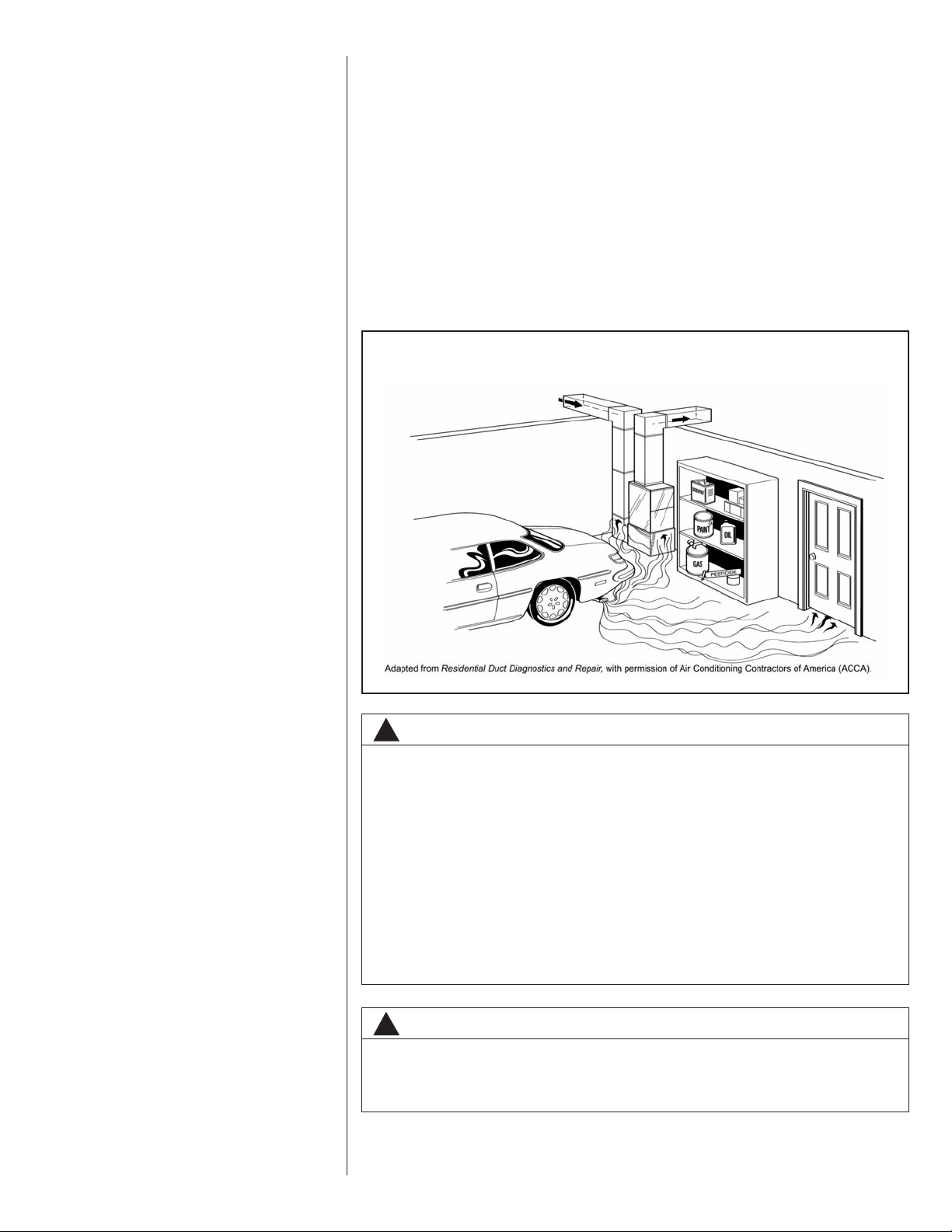
FIGURE 1
MIGRATION OF DANGEROUS SUBSTANCES, FUMES, AND ODORS INTO LIVING SPACES
WARNING
!
Duct leaks can create an unbalanced system and draw pollutants such as
dirt, dust, fumes and odors into the home causing property damage.
Fumes and odors from toxic, volatile or flammable chemicals, as well as
automobile exhaust and carbon monoxide (CO), can be drawn into the living space through leaking ducts and unbalanced duct systems causing
personal injury or death (see Figure 1).
• If air-moving equipment or ductwork is located in garages or off-garage
storage areas - all joints, seams, and openings in the equipment and
duct must be sealed to limit the migration of toxic fumes and odors
including carbon monoxide from migrating into the living space.
• If air-moving equipment or ductwork is located in spaces containing fuel
burning appliances such as water heaters or boilers - all joints, seams,
and openings in the equipment and duct must also be sealed to prevent
depressurization of the space and possible migration of combustion
byproducts including carbon monoxide into the living space.
NOTICE
!
Improper installation, or installation not made in accordance with the
Underwriters Laboratory (UL) certification or these instructions, can result
in unsatisfactory operation and/or dangerous conditions and are not covered by the unit warranty.
7
Page 8
NOTICE
!
In compliance with recognized codes, it is recommended that an auxiliary
drain pan be installed under all evaporator coils or units containing evaporator coils that are located in any area of a structure where damage to the
building or building contents may occur as a result of an overflow of the
coil drain pan or a stoppage in the primary condensate drain piping. See
accessories section of these instructions for auxiliary horizontal overflow
pan information (model RXBM).
2.2 RECEIVING
Immediately upon receipt, all cartons and contents should be inspected for transit damage. Units with damaged cartons should be opened immediately. If damage is found, it
should be noted on the delivery papers, and a damage claim filed with the last carrier.
• After unit has been delivered to job site, remove carton taking care not to damage
unit.
• Check the unit rating plate for unit size, electric heat, coil, voltage, phase, etc. to be
sure equipment matches what is required for the job specification.
• Read the entire instructions before starting the installation.
• Some building codes require extra cabinet insulation and gasketing when unit is
installed in attic applications.
• If installed in an unconditioned space, apply caulking around the power wires, control
wires, refrigerant tubing and condensate line where they enter the cabinet. Seal the
power wires on the inside where they exit conduit opening. Caulking is required to
pre-vent air leakage into and condensate from forming inside the unit, control box,
and on electrical controls.
• Install the unit in such a way as to allow necessary access to the coil/filter rack and
blower/control compartment.
• Install the unit in a level position to ensure proper condensate drainage. Make sure
unit is level in both directions within 1/8”.
• Install the unit in accordance with any local code which may apply and the national
codes. Latest editions are available from: “National Fire Protection Association, Inc.,
Batterysmarch Park, Quincy, MA 02269.” These publications are:
• ANSI/NFPA No. 70-(Latest Edition) National Electrical Code.
• NFPA90A Installation of Air Conditioning and Ventilating Systems.
• NFPA90B Installation of warm air heating and air conditioning systems.
• The equipment has been evaluated in accordance with the Code of Federal
Regulations, Chapter XX, Part 3280.
2.3 CLEARANCES
• All units are designed for “0” inches clearance to combustible material on all cabinet
surfaces.
• Some units require supply duct clearances and combustible floor bases depending on
the heating kW. The following table should be used to determine these requirements:
Model Cabinet Size 17 21 24 25
Model Designation kW 11 11 18 18
Units with electric heating kW above
ance to combustible material for the first three feet of supply plenum and ductwork.
Additionally, if these units are installed downflow, a combustible floor base is
required.
Units with electric heating kW equal to
not require supply ductwork clearances or combustible floor bases.
• Vertical units require clearance on at least one side of the unit for electrical connec-
tions. Horizontal units require clearance on either top or bottom for electrical connections. Refrigerant and condensate drain connections are made on the front of the unit.
• All units require 24 inches minimum access to the front of the unit for service.
• These units may be installed in either ventilated or nonventilated spaces.
8
that listed in the table require a one inch clear-
or less than the values listed in the table do
Page 9
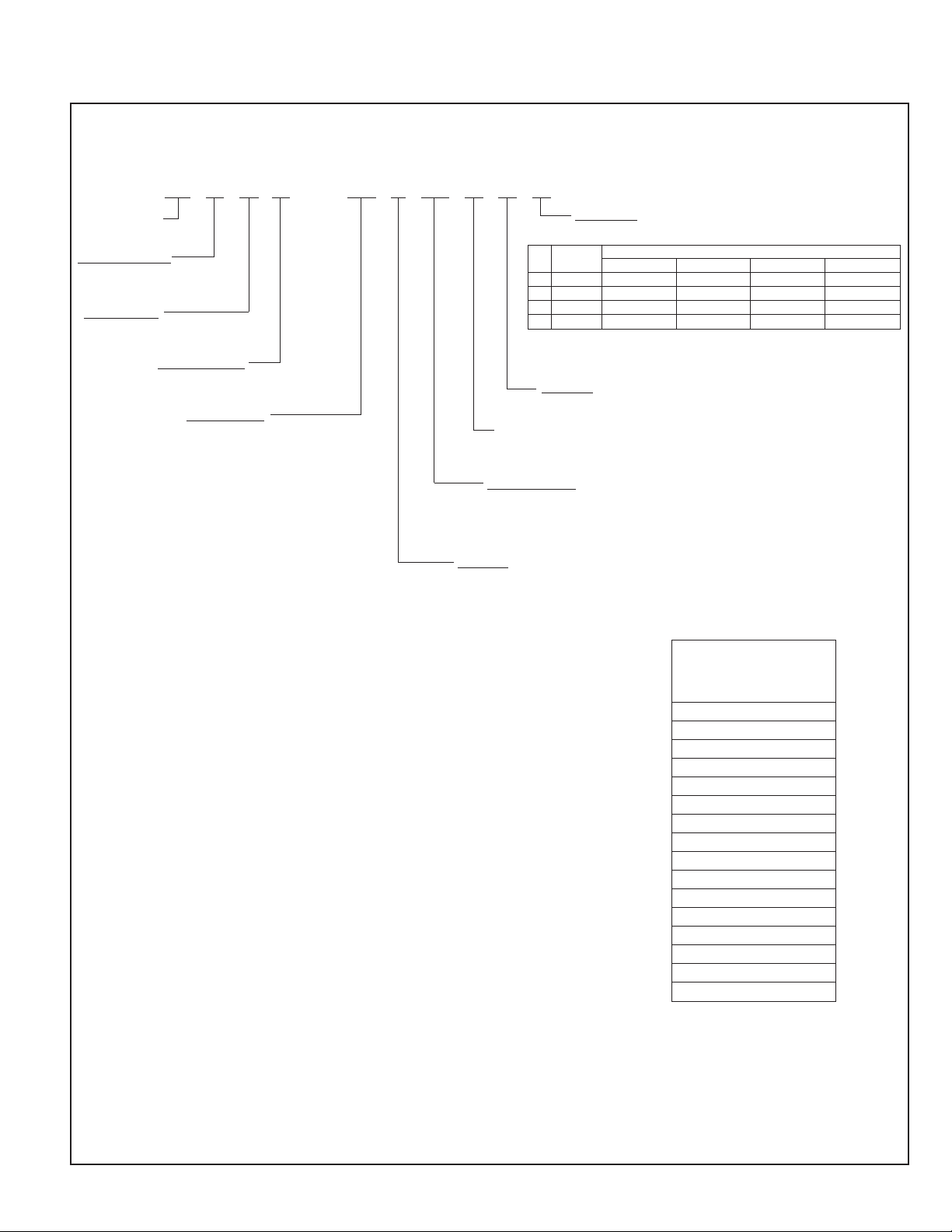
2.4 UNIT MODEL EXPLANATION
FIGURE 2
MODEL NUMBER EXPLANATION
(-) BHP—17 J 00 NHD
TRADEBRAND
CLASSIFICATION
B = BLOWER UNIT
APPLICATION
H = HEAT PUMP AIR HANDLER
DESIGN SERIES
P = X-13 MOTOR
CABINET SIZE
17 = 17.5”
21 = 21.0”
24 = 24.5”
25 = 24.5”
COIL CODE
A = NO COIL
Coil Refrigerant Cabinet Width
Code Type 17 21 24 25
1 R-410A RCHL-24A2GH17
2 R-410A RCHL-36A1GH21
4 R-410A RCHL-48A1GH24
7 R-410A RCHL-60A1GH24
AIRFLOW
HORIZONTAL MULTI-POSITION
CONTROL
N = NO CIRCUIT PROTECTION (SINGLE CIRCUIT)
S = CIRCUIT BREAKER (SINGLE CIRCUIT)
ELECTRIC HEAT
00 = NO HEAT 14 = 14.0 KW
06 = 4.9 KW 18 = 17.5 KW
07 = 7.0 KW 21 = 21.0 KW
11 = 10.0 KW
VOLTAGE
A = 115V-1-60
J = 208/240V-1-60
AVAILABLE MODELS
FEATURING R-410A
REFRIGERANT
(-)BHP-17A00NH1
(-)BHP-17J06SH1
(-)BHP-17J07SH1
(-)BHP-17J11SH1
(-)BHP-21A00NH2
(-)BHP-21J06SH2
(-)BHP-21J07SH2
(-)BHP-21J11SH2
(-)BHP-24A00NH4
(-)BHP-24J06SH4
(-)BHP-24J07SH4
(-)BHP-24J11SH4
(-)BHP-24J18SH4
(-)BHP-25A00NH7
(-)BHP-25J11SH7
(-)BHP-25J18SH7
9
Page 10
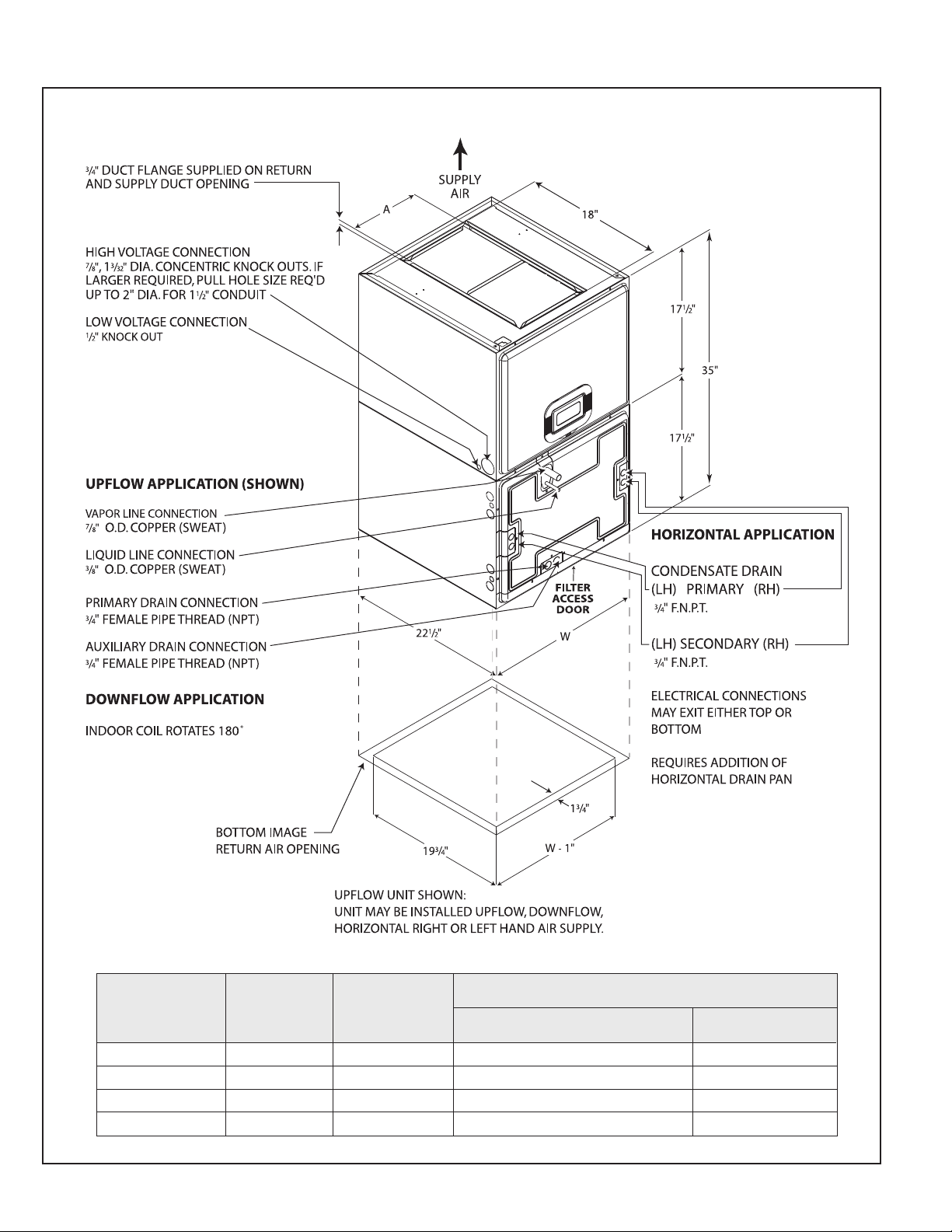
2.5 DIMENSIONS AND WEIGHTS
FIGURE 3
DIMENSIONS AND WEIGHTS
NOTE: 24” CLEARANCE REQUIRED
IN FRONT OF UNIT FOR FILTER
AND COIL MAINTENANCE.
10
DIMENSIONAL DATA
MODEL
CABINET SIZE
17 17
21 21" 97⁄16" 109/117 [383.3/411.5] 79/87 [277.8/306]
24 241⁄2" 113⁄4" 125/134 [439.6/471.3] 88/97 [309.5/341.1]
25 241⁄2" 113⁄4" 125/134 [439.6/471.3] 88/97 [309.5/341.1]
UNIT
WIDTH
“W” IN.
1
⁄2"7
SUPPLY
DUCT
“A” IN.
9
⁄16" 92/99 [323.6/348.2] 66/75 [232.1/263.8]
UNIT WEIGHT / SHIPPING WEIGHT (LBS.)*
UNIT WITH COIL
(MAX. kw.)
UNIT WITHOUT COIL
(MAX. kw.)
Page 11

WARNING
!
DO NOT INSTALL THIS UNIT IN MANUFACTURED (MOBILE) HOMES.
IMPROPER INSTALLATION IS MORE LIKELY IN MANUFACTURED HOUSING
DUE TO DUCTWORK MATERIAL, SIZE, LOCATION, AND ARRANGEMENT.
INSTALLATIONS IN MANUFACTURED HOUSING CAN CAUSE A FIRE RESULTING IN PROPERTY DAMAGE, PERSONAL INJURY OR DEATH.
EXCEPTION: MANUFACTURED HOUSING INSTALLATIONS ARE APPROVED
ONLY WITH DOCUMENTATION BY A RECOGNIZED INSPECTION AUTHORITY
THAT THE INSTALLATION HAS BEEN MADE IN COMPLIANCE WITH THE
INSTRUCTIONS AND ALL WARNINGS HAVE BEEN OBSERVED.
CAUTION
!
When used on cooling applications, excessive sweating may occur when unit
is installed in an unconditioned space. This can result in property damage.
• Some building codes require extra cabinet insulation and gasketing when
unit is installed in attic applications.
• If installed in an unconditioned space, apply caulking around the power
wires, control wires, refrigerant tubing and condensate line where they enter
the cabinet. Seal the power wires on the inside where they exit conduit
opening. Caulking is required to prevent air leakage into and condensate
from forming inside the unit, control box, and on electrical controls.
• Install the unit in such a way as to allow free access to the coil/filter compartment and blower/control compartment.
• Install the unit in a level position to ensure proper condensate drainage.
Make sure unit is level in both directions within 1/8”.
• Install the unit in accordance with any local code which may apply and the
national codes. Latest editions are available from: “National Fire Protection
Association, Inc., Batterysmarch Park, Quincy, MA 02269.” These publications
are:
• ANSI/NFPA No. 70-(Latest Edition) National Electrical Code.
• NFPA90A Installation of Air Conditioning and Ventilating Systems.
• NFPA90B Installation of warm air heating and air conditioning systems.
• The equipment has been evaluated in accordance with the Code of Federal
Regulations, Chapter XX, Part 3280.
(SEE WARNINGS IN REGARD TO DUCTWORK)
FIGURE 4
DIMENSIONS FOR FRONT CONNECT COIL
153/4”
133/4”
91/2”
71/2”
NOTE: FOR “W”
MEASUREMENT,
SEE FIGURE 3.
C
1
L
3
/4”
1.5”
2.0”
C
L
W
2.6 UNIT CONFIGURATION
All units are modular construction allowing installer to disassemble unit into two 17-1/2”
high components, coil casing and blower unit, for ease of installation, then reassemble
in location.
TO DISASSEMBLE:
Remove both access panels and remove six screws holding coil casing to blower unit,
lift blower unit from coil casing.
11
Page 12

TO REASSEMBLE:
To attach coil casing to blower unit, make sure 3/4” flanges on back and sides of
return air opening of blower casing are bent along perforated edge to inside of casing.
Clearance holes in flange should match up with drive holes on inside of blower casing. Make sure 3/4” flanges on coil casing are bent up (back and 2 sides only) on supply air side of coil casing along perforated edge. Do not bend flange on front of coil
casing. Set supply air side of coil casing (3/4” flanges) into return air opening of blower casing. Replace 6 - #8 screws through flange in coil casing, flange in blower casing
and into drive holes on inside of blower casing, two screws in back and two screws in
each side. Do not overtighten sheet metal screws, they will strip easily if overtightened.
IMPORTANT: Configure the unit with the indoor coil casing installed on air inlet
(return) side of the blower section. Do not try to configure unit with indoor coil on
discharge (supply) side of blower section.
2.7 VERTICAL UPFLOW
• Electrical connections can be made from either the left or right side of the unit.
Refrigerant and condensate drain connections are made on the front of the unit (see
Figures 3 & 4).
• If return air is to be ducted, install duct flush with floor. Use fireproof resilient gasket 1/8
to 1/4 in. thick between duct, unit and floor. Set unit on floor over opening.
WARNING
!
IF UNIT IS TO BE INSTALLED WITHOUT AN INDOOR COIL, RETURN DUCT OR
PLENUM, IT MUST NOT BE IN STALLED DIRECTLY OVER COMBUSTIBLE MATERIAL. IF INSTALLED WITHOUT AN INDOOR COIL WITH A RETURN DUCT OR
PLENUM, THE AIR PLENUM OR DUCT MUST HAVE A SOLID SHEET METAL
BOTTOM WITH NO RETURN AIR OPENINGS, REGISTERS OR FLEXIBLE AIR
DUCTS LOCATED DIRECTLY UNDER THE UNIT. EXPOSING COMBUSTIBLE
MATERIAL TO THE RETURN OPENING OF AN UPFLOW UNIT WITHOUT AN
INDOOR COIL CAN CAUSE A FIRE RESULTING IN PROPERTY DAMAGE, PERSONAL INJURY OR DEATH.
2.8 VERTICAL DOWNFLOW
Conversion to Vertical Downflow: A vertical upflow unit may be converted to vertical
downflow. (See Figure 3)
• Remove the indoor coil.
• Install coil rails in the top of the coil box (supplied).
• Rotate unit into the downflow position, with the coil compartment on top and the blower compartment on bottom.
• Reinstall the indoor coil in its new position.
• Rotate the circuit breaker(s) 180° (see instructions for rotating breaker(s) that follow).
IMPORTANT NOTE:
• In a downflow configuration the internal air filter must not be used.
• A remote air filter should be installed in the return air system
• The remote air filter should be sized for a maximum of 300 feet per minute of air velocity for the CFM required.
12
Page 13

FIGURE 5
ROTATING CIRCUIT BREAKER
IMPORTANT: To comply with certification agencies and the National Electric
Code, units with circuit breaker(s) on vertical units must have circuit breakers
installed so that the breaker switch “on” position and marking is up and, “off”
position and marking is down.
- To turn breaker(s): Rotate one breaker pair (circuit) at a time starting with the one on the
right. Loosen both lugs on the load side of the breaker. Wires are bundles with wire ties,
one bundle going to the right lug and one bundle going to the left lug.
- Using a screwdriver or pencil, lift white plastic tab with hole away from breaker until
breaker releases from mounting opening (see Figure 5).
- With breaker held in hand, rotate breaker so that “on” position is up, “off” position is down
with unit in planned vertical mounting position. Insert right wire bundle into top right
breaker lug, ensuring all strands of all wires are inserted fully into lug, and no wire insulation is in lug.
- Tighten lug as tight as possible while holding circuit breaker. Check wires and make sure
each wire is secure and none are loose. Repeat for left wire bundle in left top circuit
breaker lug.
- Replace breaker by inserting breaker mounting tab opposite white pull tab in opening,
hook mounting tab over edge in opening.
- With screwdriver or pencil, pull white tab with hole away from breaker while setting that
side of breaker into opening. When breaker is in place, release tab, locking circuit breaker into location in opening.
- Repeat above operation for remaining breaker(s) (if more than one is provided).
- Replace single point wiring jumper bar, if it is used, on line side of breaker and tighten
securely.
- Double check wires and lugs to make sure all are secure and tight. Check to make sure
unit wiring to circuit breaker load lugs match that shown on the unit wiring diagram.
• Electrical connections can be made from either the left or right side of the unit.
Refrigerant and condensate drain connections are made on the front of the unit (see
Figure 4).
• RXBB-AA combustible floor base is used for all unit sizes. Unit must be centered on
combustible base in the width dimension (14
WARNING
!
THE RXBB-AA COMBUSTIBLE FLOOR BASE IS REQUIRED WHEN SOME
UNITS WITH ELECTRIC HEAT ARE APPLIED DOWNFLOW ON COMBUSTIBLE
FLOORING. FAILURE TO USE THE BASE CAN CAUSE A FIRE RESULTING IN
PROPERTY DAMAGE, PERSONAL INJURY OR DEATH. SEE CLEARANCES
FOR UNITS REQUIRING A COMBUSTIBLE FLOOR BASE.
3
/8”).
13
Page 14

WARNING
!
THE FIRST 36 INCHES OF SUPPLY AIR PLENUM AND DUCTWORK MUST BE
CONSTRUCTED OF SHEET METAL AS REQUIRED BY NFPA 90B. THE SUPPLY
AIR PLENUM OR DUCT MUST HAVE A SOLID SHEET METAL BOTTOM
DIRECTLY UNDER THE UNIT WITH NO OPENINGS, REGISTERS OR FLEXIBLE
AIR DUCTS LOCATED IN IT. IF FLEXIBLE SUPPLY AIR DUCTS ARE USED THEY
MAY BE LOCATED ONLY IN THE VERTICAL WALLS, OF A RECTANGULAR
PLENUM, A MINIMUM OF 6 INCHES FROM THE SOLID BOTTOM. METAL
PLENUM OR DUCT MAY BE CONNECTED TO THE COMBUSTIBLE FLOOR
BASE, IF NOT, IT MUST BE CONNECTED TO THE UNIT SUPPLY DUCT
FLANGES SUCH THAT COMBUSTIBLE FLOOR OR OTHER COMBUSTIBLE
MATERIAL IS NOT EXPOSED TO THE SUPPLY AIR OPENING FROM THE
DOWNFLOW UNIT. EXPOSING COMBUSTIBLE (NON-METAL) MATERIAL TO
THE SUPPLY OPENING OF A DOWNFLOW UNIT CAN CAUSE A FIRE RESULTING IN PROPERTY DAMAGE, PERSONAL INJURY OR DEATH.
EXCEPTIONS TO DOWNFLOW WARNINGS:
• INSTALLATIONS ON CONCRETE FLOOR SLAB WITH SUPPLY AIR PLENUM
AND DUCTWORK COMPLETELY ENCASED IN NOT LESS THAN 2 INCHES OF
CONCRETE (SEE NFPA 90B).
• INSTALLATIONS OF UNITS WITHOUT ELECTRIC HEATERS.
2.9 HORIZONTAL
Units with an “H” (left-hand air supply) in the airflow direction position in the model number
have factory configured evaporator coils for installation in the horizontal position.
Conversion to Horizontal: A vertical upflow evaporator coil may be converted to horizontal by removing the indoor coil and installing horizontal drain pan on coil as shown for right
hand or left hand air supply. Reinstall coil in unit as shown for right or left hand air supply.
See Figures 6 & 7.
Conversion in Horizontal Direction: Evaporator coils configured for horizontal left-hand
supply can be changed to horizontal right-hand supply by removing the indoor coil and
installing the drain pan as shown in Figures 6 & 7 for appropriate air supply direction.
FIGURE 6
INDOOR COIL AND DRAIN PAN SET-UP
HORIZONTAL LEFT-HAND AIR SUPPLY
CAUTION
!
HORIZONTAL UNITS MUST BE CONFIGURED FOR RIGHT HAND AIR SUPPLY
OR LEFT HAND AIR SUPPLY. HORIZONTAL DRAIN PAN MUST BE LOCATED
UNDER INDOOR COIL. FAILURE TO USE THE DRAIN PAN CAN RESULT IN
PROPERTY DAMAGE.
Horizontal Drain Pan Model RXBD-CB: This drain pan is used on all coil models and
fits all unit sizes either right or left hand air supply.
• Install horizontal drain pan as shown for right hand or left hand supply. Drain pan connections must be toward front of coil (header connection end). Install coil assembly
FIGURE 7
INDOOR COIL AND DRAIN PAN SET-UP
HORIZONTAL RIGHT-HAND AIR SUPPLY
14
I156
I156
Page 15

into horizontal pan as shown with coil endplates fitting into “V” shaped supports in the
front and back of the horizontal pan. Mounting tabs on vertical drain pan fit over the
air inlet side of the horizontal pan with vertical pan inside horizontal drain pan.
Horizontal pan must be under indoor coil when in the installed position. Note primary
and auxiliary drain pan positions for horizontal right vs. horizontal left. Drain connection with 3/4” hole must be connected to primary drain. Connection with 3/8” knockout
is the secondary drain connection.
Electrical connections may be made from the top or bottom of the unit. Refrigerant
and condensate drain connections must be made on the front of the unit. (See unit
dimensions and horizontal right hand supply and horizontal left hand supply, Figures
3, 6 & 7.)
IMPORTANT: Units cannot be installed horizontally laying on or suspended from the
back of the unit. Horizontal units must be supported or suspended from one side or the
other when in the horizontal position.
• Support along the length of the unit, all units installed horizontally. Do not support or
suspend unit from both ends without support in the center of the cabinet. If unit is to
be supported or suspended from corners, run two reinforcing rails length of unit and
support or suspend from reinforcing rails.
NOTE: When converting a vertical upflow to horizontal, the foam tape must be removed
from both sides of the vertical pan going into the horizontal pan. When converting a
horizontal left-hand to horizontal right-hand, the foam tape must be moved to the
appropriate location.
WARNING
!
THE SUPPLY AIR PLENUM OR DUCT MUST HAVE A SOLID SHEET METAL
BOTTOM WITH NO SUPPLY AIR OPENINGS, REGISTERS OR FLEXIBLE AIR
DUCTS LOCATED IN IT FOR THE FIRST 36 INCHES OF HORIZONTAL SURFACE
ON UNITS WITH ELECTRIC HEATERS. FAILURE TO OBSERVE SUPPLY
PLENUM, DUCT WARNINGS CAN CAUSE A FIRE RESULTING IN PROPERTY
DAMAGE, PERSONAL INJURY OR DEATH.
3.0 ELECTRICAL WIRING
Field wiring must comply with the National Electric Code (C.E.C. in Canada) and any
applicable local ordinance.
3.1 POWER WIRING
It is important that proper electrical power is available for connection to the unit model
being installed. See the unit nameplate, wiring diagram and electrical data in the installation instructions.
• If required, install a branch circuit disconnect of adequate size, located within sight of,
and readily accessible to the unit.
• Units with factory installed circuit breaker(s) meet UL and CSA requirements as a service disconnect and should make above requirement for a field installed branch circuit
disconnect unnecessary.
• IMPORTANT: Units may be equipped with one, two, or three 60 amp. circuit breakers.
These breaker(s) protect the internal wiring in the event of a short circuit and serve as
a disconnect. Circuit breakers installed within the unit do not provide over-current protection of the supply wiring and therefore may be sized larger than the branch circuit
protection.
• Supply circuit power wiring must be 75°C minimum copper conductors only. See electrical data for ampacity, wire size and circuit protector requirement. Supply circuit protective devices may be either fuses or “HACR” type circuit breakers.
• Power wiring may be connected to either the right or left side (vertical) top or bottom
(horizontal). A 7/8”, 1-3/32” dia. concentric knockout is provided for connection of
power wiring to unit. If a larger opening is required, dependent upon kW electric heat
supplied, pull appropriate size hole required for conduit size being used. Using a conduit hole punch (Greenlee type), center punch using outside cabinet around 7/8”
knockout as a template to center punch location and punch desired hole size. Holes
may be punched for any size conduit up to a 2” hole for 1-1/2” con duit.
• Power wiring is connected to either the power terminal block or circuit breaker(s) in
unit control compartment.
•Single phase units above 10.5 kW may be supplied with circuit breaker(s) requiring
separate supply circuits. Units come standard with a jumper bar assembly connecting
separate circuits into one single supply circuit (excluding 18 kW and 21 kW “C” voltage units).
15
Page 16

• Jumper bar assemblies are connected to the line side lugs of the circuit breakers.
Jumper bar is assembled for left (upflow) cabinet power wiring entrance. To convert to
right (upflow) power entrance: Remove jumper cover, remove jumper bar from circuit
breakers, remove screw on back holding left lug in upper hole to bar, reassemble lug
in lower hole and retighten screw. Use the same procedure to move the right lug to
the upper mounting hole. Reassemble jumper bar into circuit breakers and tighten
lugs. Jumper bar is now ready for wiring from the opposite side.
• If a factory supplied jumper bar for single supply circuit is removed from unit to make
multiple supply circuits the line side of the individual circuit breakers must be covered
with finger safe covers. (See information on accessories for part numbers.)
• After wiring is complete, make sure finger safe cover(s) are replaced over circuit
breaker(s) lugs covering lug where field connections are made. On units with jumper
bar, make sure jumper bar cover is replaced and secured in place. Covers provided
for jumper bar must have side of cover broken off on the side wiring has been connected so that field supply will clear under appropriate side of cover. Units with circuit
breakers must have covers in place to meet requirements as a service disconnect.
3.2 CONTROL WIRING
IMPORTANT: Class 2 low voltage control wire should not be run in conduit with
power wiring and must be separated from power wiring, unless class 1 wire of
proper voltage rating is used.
• Low voltage control wiring should be 18 AWG color-coded (105°C minimum). For
lengths longer than 100 ft., 16 AWG wire should be used.
• Control wiring should be routed through 1/2” dia. knockout near power wiring
entrance on either left or right side of unit. After opening selected knockout, install
bushing (supplied in parts bag) in openings.
• If control wiring is routed through right side (upflow), it must be routed through extruded holes in lower front of blower housing behind power raceway to the left side of
blower housing. If routed through left side (upflow), it should be routed through
extruded hole in lower front left blower side.
• Field control connections are made to terminals extending from left side of control
compartment (upflow position).
• See wiring diagrams attached to indoor and outdoor sections to be connected, control
wiring diagram booklet supplied with outdoor heat pump section, or Figures 8 and 9.
• Do not leave excess field control wiring inside unit, pull excess control wire to outside
of unit and provide strain relief for field control wiring on inside of cabinet at point
wiring penetrates cabinet.
• Make sure, after installation, separation of control wiring and power wiring has been
maintained.
16
3.3 GROUNDING
WARNING
!
THE UNIT MUST BE PERMANENTLY GROUNDED. FAILURE TO DO SO CAN
RESULT IN ELECTRICAL SHOCK CAUSING PERSONAL INJURY OR DEATH.
• Grounding may be accomplished by grounding metal conduit when installed in accordance with electrical codes to the unit cabinet.
• Grounding may also be accomplished by attaching ground wire(s) to ground lug(s)
provided in the unit wiring compartment.
• Ground lug(s) are located close to wire entrance on left side of unit (upflow). Lug(s)
may be moved to marked locations near wire entrance on right side of unit (upflow), if
alternate location is more convenient.
• Use of multiple supply circuits require grounding of each circuit to lug(s) provided in
unit.
Page 17

3.4 BLOWER MOTOR ELECTRICAL DATA: “A” VOLTAGE (115V)
MODEL
SIZE/ELEC.
DESIGNATION
(-)BHP-17A00NH* 115 1 60 1/3 [249] 300-1100 5 3.3 5.0 15
(-)BHP-21A00NH* 115 1 60 1/2 [373] 300-1100 5 5.0 7.0 15
(-)BHP-24A00NH* 115 1 60 3/4 [559] 300-1100 5 5.8 8.0 15
(-)BHP-25A00NH* 115 1 60 3/4 [559] 300-1100 5 7.7 10.0 15
VOLTAGE
HERTZPHASE
HP
[W]
SPEEDSRPM
CIRCUIT
AMPS.
MINIMUM
CIRCUIT
AMPACITY
MAXIMUM
PROTECTOR
3.5 BLOWER MOTOR ELECTRICAL DATA: “J” VOLTAGE (208/240V)
MODEL
SIZE/ELEC.
DESIGNATION
(-)BHP-17J00NH* 208/240 1 60 1/3 [249] 300-1100 5 2.0 3.0 15
(-)BHP-21J00NH* 208/240 1 60 1/2 [373] 300-1100 5 3.1 4.0 15
(-)BHP-24J00NH* 208/240 1 60 3/4 [559] 300-1100 5 4.2 6.0 15
(-)BHP-25J00NH* 208/240 1 60 3/4 [559] 300-1100 5 5.7 8.0 15
VOLTAGE
HERTZPHASE
HP
[W]
SPEEDSRPM
CIRCUIT
AMPS.
MINIMUM
CIRCUIT
AMPACITY
MAXIMUM
PROTECTOR
3.6 ELECTRIC HEAT ELECTRICAL DATA
Model Size/
Elec./KW
Designation
(-)BHP-17J06SH* 3.7/4.9 1/60 2/2.5 Single Circuit 19.8/22.4 25/29 25/30
(-)BHP-17J07SH* 5.3/7.0 1/60 2/3.5 Single Circuit 27.5/31.2 35/39 40/40
(-)BHP-17J11SH* 7.5/10.0 1/60 3/3.3 Single Circuit 38.1/43.7 48/55 50/60
(-)BHP-21J06SH* 3.7/4.9 1/60 2/2.5 Single Circuit 20.9/23.5 27/30 30/30
(-)BHP-21J07SH* 5.3/7.0 1/60 2/3.5 Single Circuit 28.6/32.3 36/41 40/45
(-)BHP-21J11SH* 7.5/10.0 1/60 3/3.3 Single Circuit 39.2/44.8 49/56 50/60
(-)BHP-24J06SH* 3.7/4.9 1/60 2/2.5 Single Circuit 22.0/24.6 28/31 30/35
(-)BHP-24J07SH* 5.3/7.0 1/60 2/3.5 Single Circuit 29.7/33.4 38/42 40/45
(-)BHP-24J11SH* 7.5/10.0 1/60 3/3.3 Single Circuit 40.3/45.9 51/58 60/60
(-)BHP-24J18SH* 5.3/7.0 1/60 2/3.5 Multiple Ckt. 1 29.7/33.4 38/42 40/45
(-)BHP-25J11SH* 7.5/10.0 1/60 3/3.3 Single Circuit 91.8/47.4 53/60 60/60
(-)BHP-25J18SH* 5.3/7.0 1/60 2/3.5 Multiple Ckt. 1 31.2/39.9 39/44 40/45
Heater
KW
Volts
208/240
13.2/17.5 5/3.5 Single Circuit 67.7/77.1 85/97 90/100
7.9/10.5 3/3.5 Multiple Ckt. 2 39.0/43.8 48/55 50/60
13.2/17.5 5/3.5 Single Circuit 69.2/78.6 87/99 90/100
7.9/10.5 3/3.5 Multiple Ckt. 2 38.0/43.8 48/55 50/60
PH/HZ
Heater
No./KW
@ 240V
Type Supply Circuit
Single Circuit
Multiple Circuit
Circuit
Amps.
Minimum
Circuit
Ampacity
Maximum
Circuit
Protector
CIRCUIT
CIRCUIT
Supply circuit protective devices may be fuses or “HACR” type circuit breakers. Largest motor load is included in single circuit and circuit 1 multiple circuit. If nonstandard fuse size is specified, use next size larger standard fuse size.
17
Page 18

w
W2
G
Y
W1
B
C
R
Air Handler
Control Board
G
Y
C
R
Single-Stage A/C Thermostat
A/C Outdoor Unit
Y
C
Y
G/BK
BR
R
Y
BR
FIGURE 8
B
W2
G
Y
W1
B
C
R
Air Handler
Control Board
Y
G
W2
E
Heat Pump Thermostat
Heat Pump
Outdoor Unit
C
R
Y
B
C
R
D
Y
G/BK
BR
W/BL
W/BK
BL
BR
R
Y
BL
R
P
*
TYPICAL THERMOSTAT WIRING – STRAIGHT COOLING WITH ELECTRIC HEAT
FIGURE 9
HEAT PUMP WITH ELECTRIC HEAT
Purple
*Recommitted to jump W1 and W2 together for maximum temperature rise
18
Page 19

4.0 DUCTWORK
Field ductwork must comply with the National Fire Protection Association NFPA 90A,
NFPA 90B and any applicable local ordinance.
WARNING
!
UNITS ARE FOR DUCTED APPLICATIONS ONLY. A MINIMUM OF 36 INCHES OF
SUPPLY AIR PLENUM AND DUCTWORK IS REQUIRED. NO SUPPLY AIR OPENINGS, REGISTERS OR FLEXIBLE AIR DUCTS MAY BE LOCATED WITHIN THE
FIRST 36 INCHES OF SUPPLY PLENUM AND DUCTWORK ON UNITS WITH
ELECTRIC HEATERS. FAILURE TO OBSERVE SUPPLY PLENUM/DUCT WARNINGS CAN CAUSE A FIRE RESULTING IN PROPERTY DAMAGE, PERSONAL
INJURY OR DEATH.
Sheet metal ductwork run in unconditioned spaces must be insulated and covered with a
vapor barrier. Fibrous ductwork may be used if constructed and installed in accordance
with SMACNA Construction Standard on Fibrous Glass Ducts. Ductwork must comply
with National Fire Protection Association as tested by U/L Standard 181 for Class I Air
Ducts. Check local codes for requirements on ductwork and insulation.
• Duct system must be designed within the range of external static pressure the unit is
designed to operate against. It is important that the system airflow be adequate. Make
sure supply and return ductwork, grills, special filters, accessories, etc. are accounted
for in total resistance. See airflow performance tables in this manual.
• Design the duct system in accordance with “ACCA” Manual “D” Design for Residential
Winter and Summer Air Conditioning and Equipment Selection. Latest editions are
available from: “ACCA” Air Conditioning Contractors of America, 1513 16th Street,
N.W., Washington, D.C. 20036. If duct system incorporates flexible air duct, be sure
pressure drop information (straight length plus all turns) shown in “ACCA” Manual
“D” is accounted for in system.
• Supply plenum is attached to the 3/4” duct flanges supplied on the unit around the
blower outlet. Flanges are flat for shipping purposes and must be bent up along perforated edge around blower opening. Be sure to bend flanges completely up so they do
not interfere with air being discharged from blower.
IMPORTANT: Flanges around blower opening for attaching supply duct must be
bent up out of blower discharge even if not used so they do not restrict airflow
from blower.
• Supply plenum should be the same size as the flanges provided around the blower
outlet. Ideally, it should extend 3 feet from the unit before turning or branching off
plenum into duct runs. The plenum forms an extension of the blower housing and
minimizes air expansion losses from the blower. Changing the size, shape or length
will degrade blower performance. If supply discharges directly into a larger duct or
plenum as much as .1” W.C., static pressure will be lost. If 3 feet is not possible, even
6, 12 or 18 inches will help.
IMPORTANT: If an elbow is included in the plenum close to the unit, it must not be
smaller than the dimensions of the supply duct flange on the unit.
• Some units with electric heaters require 1 in. clearance to supply plenum and branch
ducts to combustible material for the first 3 feet from the unit. See CLEARANCES.
• A 3/4” return duct flange is supplied on all sides of the air inlet opening of the unit coil
casing. If the unit is to be installed without a coil casing (no indoor coil), a 3/4” flange
is supplied on the back and sides of the air inlet opening of the blower casing. No
flange is provided on the front of the opening to the blower casing. If return duct is
attached to the inlet of the blower casing, the front flange of the duct should be run up
into the opening or 90° brake made on the front flange to tape to the front of the blower casing.
• IMPORTANT: The front flange on the return duct if connected to the blower cas-
ing must not be screwed into the area where the power wiring is located. Drills
or sharp screw points can damage insulation on wires located inside unit.
• Return duct flanges on blower or coil casing are flat for shipping purposes and must
be bent out along perforated edge around opening.
• Secure the supply and return ductwork to the unit flanges, using proper fasteners for
the type of duct used and tape the duct-to-unit joint as required to prevent air leaks.
(SEE SPECIFIC AIRFLOW POSITION FOR ADDITIONAL
WARNINGS)
19
Page 20

5.0 REFRIGERANT CONNECTIONS
Keep coil connections sealed until refrigerant connections are to be made. See outdoor
unit manual for details on line sizing, tubing installation, evacuation and charging information.
• To install the refrigerant connections, first install the refrigerant block-off plate (located in the Parts Bag, see Figure 10) around the refrigerant connections. Braze all fittings. When refrigerant lines have cooled, insert the foam gasket (located in the parts
bag, see Figure 10) around the refrigerant lines, between the coil and the refrigerant
block-off plate.
IMPORTANT: The refrigerant block-off plate MUST be installed around the refrigerant connections before brazing.
• When making braze connections close to outside of cabinet, use a brazing shield to
protect cabinet paint from being damaged from torch flame.
• If the installation is in a tight location, it might be convenient to make some external
tubing connections before setting unit in place.
IMPORTANT: Install refrigerant tubing so it does not block service access to front of unit.
24 in. clearance is required for filter, coil or blower removal and service access.
FIGURE 10
REFRIGERANT BLOCK-OFF PLATE AND FOAM GASKET
20
5.1 FLOWCHECK PISTONS
See outdoor unit installation instructions for correct flowcheck piston sizes and proper
piston installation instructions.
• Indoor coil piston size is indicated by the digits underscored in the indoor coil model
number.
IMPORTANT: It is important that the proper piston sizes be used dependent on
indoor coil, outdoor unit combination and application.
Page 21

6.0 CONDENSATE DRAIN TUBING
Consult local codes or ordinances for specific requirements that may apply.
• The coil door is shipped from the factory with the condensate drain knockout
attached. Knockout must be removed and the condensate block-off plate (included in
parts bag, see Figure 11) must be installed to access the front drain.
• Vertical units (vertical drain pan) are supplied with a 3/4” female pipe thread primary
drain connection and a 3/4” female pipe thread auxiliary drain connection. (See unit
dimensions figures for drain locations.)
IMPORTANT: Side drain connections on vertical drain pans have a plastic web
covering opening. Connection(s) used must be broken out before connection(s)
are made. Break out only connection(s) to be used. Front drain connections have
removable threaded plastic plugs factory installed. Plugs must be removed before
connections are made; do not remove plugs if these connections are not used.
• Horizontal units (horizontal drain pan) are supplied with a 3/4” female pipe thread primary drain connection and a 3/4” female pipe thread auxiliary drain connection. (See
unit dimensions and position figures for drain locations).
IMPORTANT: All horizontal pans have plastic web over the secondary drain connection. Plastic web covering secondary connection must be broken out if used.
Secondary connection is lowered by 3/8”. Do not get primary and secondary connections interchanged.
• Removal of door knockouts required for drain connections can be made much easier
with the door removed from the cabinet.
• Install drain lines so they do not block service access to front of unit. 24 in. clearance
is required for filter, coil or blower removal and service access.
• Make sure unit is level or pitched slightly toward primary drain connection so that
drain pan will drain completely without water standing in pan.
FIGURE 11
CONDENSATE BLOCK-OFF PLATE
IMPORTANT: 2-6" PVC lengths are provided for making drain connection. When
making drain fitting connections to drain pan, use a thin layer of teflon paste, silicone or teflon tape and install hand tight.
IMPORTANT: When making drain fitting connections to drain pan, do not over
torque. Overtorquing fittings can split pipe connections on drain pan.
• Do not reduce drain line size less than connection size provided on condensate drain
pan.
• All drain lines must be pitched downward away from the unit a minimum of 1/8 in. per
foot of line to ensure proper drainage.
• Do not connect condensate drain line to a closed or open sewer pipe. Run condensate to an open drain or outdoors.
• The drain line should be insulated where necessary to prevent sweating and damage
due to condensate forming on the outside surface of the line.
21
Page 22

• Make provisions for disconnecting and cleaning of the primary drain line should it
become necessary.
• Install a 2 in. trap in the primary drain line as close to the unit as possible. Make sure
that the top of the trap is below connection to the drain pan to allow complete
drainage of pan.
IMPORTANT: Do not operate unit without a drain trap (see Figure 12). The condensate drain is on the negative side of the blower, therefore, air being pulled in
through the condensate line will prevent positive drainage without a proper trap.
• Auxiliary drain if used should be run to a place where it will be noticeable if it become
operational. Occupant should be warned that a problem exists if water should begin
running from the auxiliary drain line.
• Test condensate drain pan and drain line after installation is complete. Pour several
quarts of water into drain pan, enough to fill drain trap and line. Check to make sure
drain pan is draining completely, no leaks are found in drain line fittings, and water is
draining from the termination of the primary drain line.
FIGURE 12
CONDENSATE DRAIN TRAP
ST-A1244-01-01
7.0 AIR FILTER
The unit internal air filter should only be used if the unit is readily accessible for filter
cleaning or replacing.
• If unit is not readily accessible for filter maintenance, a remote filter should be
installed in the return air system.
• If a remote filter is installed, it should be sized for a maximum of 300 feet/min. air
velocity for the CFM required..
IMPORTANT: Do not operate system without a filter. A filter is required to protect
the coil, blower and internal parts from excessive dirt and dust.
• See unit position figures for location of filter in unit cabinet and service panel giving
access to unit filter.
IMPORTANT NOTE:
• In a downflow configuration the internal air filter must not be used.
• A remote air filter should be installed in the return air system
• The remote air filter should be sized for a maximum of 300 feet per minute of air velocity for the CFM required.
8.0 AIRFLOW PERFORMANCE
Airflow performance data is based on cooling performance with a coil and filter in
place. Select performance table for appropriate unit size, voltage and number of electric
heaters to be used. Make sure external static applied to unit allows operation within the minimum and maximum limits shown in table on next page for both cooling and electric heat
operation. For optimum blower performance, operate the unit in the .2” to .5” in. W.C. external static range. In general, the indoor motor speed tap should be as shown in table for the
appropriate cooling capacity shown. Always check to make sure proper motor speed tap is
connected as units are shipped from the factory connected for high speed operation (Speed
Tap 5).
22
Page 23

8.1 AIRFLOW OPERATING LIMITS
Nominal
Speed Tap
Volts 0.1 [.02] 0.2 [.05] 0.3 [.07] 0.4 [.10] 0.5 [.12] 0.6 [.15] 0.7 [.17] 0.8 [.20] 0.9 [.23] 1.0 [.25]
none 2 208/240
659 [311]
(74)
625 [294] (80)
581 [274]
(84)
539 [254]
(88)
------
none 3 208/240
790 [372]
(98)
759 [358]
(105)
722 [340]
(113)
687 [324]
(119)
650 [306]
(126)
615 [290]
(131)
573 [270]
(139)
552 [260]
(145)
507 [239]
(150)
460 [217]
(155)
3 (max.) 2 208/240
649 [306]
(79)
615 [290] (84)
571 [269]
(88)
529 [249]
(92)
------
3 (max.) 3 208/240
773 [365]
(110)
736 [347]
(113)
699 [330]
(118)
677 [320]
(126)
640 [302]
(132)
605 [286]
(141)
563 [266]
(146)
542 [256]
(154)
497 [235]
(157)
450 [212]
(162)
none 2 115
651 [307]
(76)
627 [295] (82)
583 [275]
(86)
541 [255]
(90)
------
none 3 115
776 [366]
(105)
743 [351]
(109)
724 [342]
(118)
687 [324]
(122)
658 [311]
(131)
617 [291]
(136)
595 [281]
(144)
555 [262]
(148)
517 [244]
(152)
460 [217]
(162)
none 4 208/240
844 [398]
(141)
819 [386]
(146
799 [377]
(155)
764 [360]
(160)
------
none 5 208/240
958 [452]
(162)
934 [440]
(172)
914 [431]
(176)
888 [419]
(186)
855 [403]
(189)
816 [380]
(210)
785 [370]
(204)
760 [358]
(214)
708 [334]
(223)
672 [317]
(226)
3 (max.) 4 208/240
834 [393]
(146)
809 [831]
(150)
789 [372]
(159)
754 [355]
(164)
------
3 (max.) 5 208/240
946 [446]
(179)
922 [435]
(189)
902 [426]
(193)
876 [413]
(203)
843 [398]
(206)
804 [380]
(216)
773 [365]
(221)
748 [353]
(231)
696 [328]
(240)
660 [311]
(243)
none 4 115
846 [399]
(143)
821 [387]
(148)
801 [378]
(157)
766 [361]
(162)
------
none 5 115
964 [455]
(167)
945 [446]
(178)
914 [431]
(181)
888 [419]
(191)
861 [406]
(196)
821 [387]
(205)
787 [372]
(210)
761 [359]
(218)
726 [342]
(220)
690 [326]
(230)
none 2 208/240
1068 [504]
(138)
1041 [491]
(147)
1001 [472]
(153)
972 [458]
(161)
------
none 3 208/240
1187 [560]
(180)
1162 [548]
(188)
1125 [530]
(192)
1099 [518]
(200)
1058 [499]
(208)
1013 [478]
(215)
982 [463]
(223)
951 [448]
(232)
899 [424]
(234)
855 [403]
(237)
4 (max.) 2 208/240
1035 [488]
(143)
1007 [475]
(152)
966 [455]
(158)
936 [441]
(169)
------
4 (max.) 3 208/240
1157 [546]
(182)
1132 [534]
(192)
1095 [517]
(198)
1069 [505]
(209)
1028 [485]
(218)
983 [464]
(228)
952 [449]
(239)
921 [435]
(250)
869 [410]
(255)
825 [389]
(262)
none 2 115
1070 [504]
(138)
1043 [492]
(147)
1004 [473]
(153)
974 [459]
(161)
------
none 3 115
1138 [537]
(175)
1113 [525]
(186)
1075 [507]
(191)
1053 [497]
(203)
1004 [474]
(210)
957 [451]
(216)
932 [440]
(226)
901 [425]
(231)
855 [404]
(242)
800 [378]
(252)
none 4 208/240
1269 [598]
(207)
1236 [583]
(219)
1174 [554]
(226)
1149 [542]
(236)
------
none 5 208/240
1397 [659]
(287)
1377 [649]
(307)
1346 [635]
(317)
1318 [622]
(320)
1291 [609]
(322)
1264 [596]
(319)
1234 [582]
(312)
1190 [561]
(326)
1155 [545]
(351)
1126 [531]
(368)
4 (max.) 4 208/240
1241 [585]
(222)
1208 [570]
(234)
1174 [554]
(241)
1149 [542]
(251)
------
4 (max.) 5 208/240
1366 [645]
(302)
1346 [635]
(313)
1315 [621]
(323)
1287 [608]
(331)
1260 [595]
(341)
1233 [582]
(346)
1203 [568]
(358)
1159 [547]
(371)
1124 [530]
(381)
1095 [517]
(387)
none 4 115
1269 [598]
(207)
1236 [583]
(219)
1174 [554]
(226)
1149 [542]
(236)
------
none 5 115
1370 [646]
(292)
1343 [634]
(302)
1309 [618]
(309)
1285 [607]
(319)
1258 [594]
(330)
1221 [576]
(336)
1182 [558]
(348)
1147 [542]
(357)
1117 [527]
(366)
1080 [510]
(375)
3.0-ton Air
Flow
Model
Cabinet
Size
Electric
Heaters
Blower Motor
CFM [L/s] (Watts)/External Static Pressure-Inches W.C. [kPa] with filter & indoor coil
Tonnage
-17
-21
2.0-ton Air
Flow
1.5-ton Air
Flow
2.5-ton Air
Flow
Model/Cabinet Size 17 21 24 25
Cooling BTU/H 18000 24000 30000 36000 42000 48000 60000 60000
Cooling Tons Nominal 1.5 2 2.5 3 3.5 45 5
Heat Pump or Air Conditioning
Maximum Heat/Cool CFM 675 900 1125 1350 1575 1800 2025 2250
(37.5 CFM/1,000 BTUH)
(450 CFM/Ton Nominal)
Heat Pump or Air Conditioning
Nominal Heat/Cool CFM 600 800 1000 1200 1400 1600 1800 2000
(33.3 CFM/1,000 BTUH)
(400 CFM/Ton Nominal)
Heat Pump or Air Conditioning
Minimum Heat/Cool CFM 540 720 900 1080 1260 1440 1620 1800
(30.0 CFM/1,000 BTUH)
(360 CFM/Ton Nominal)
Maximum kW Electric Heating 11 11 11 11 18 18 18 18
& Minimum Electric Heat CFM 560 560 900 1220 1220 1220 1460 1460
Maximum Electric Heat Rise °F 85 85 35 35 65 65 43 43
See Airflow Performance Data for recommended blower motor speed.
8.2 AIRFLOW PERFORMANCE DATA
23
Page 24

none 2 208/240
1438 [678]
(205)
1409 [664]
(217)
1375 [648]
(229)
1341 [632]
(252)
------
none 3 208/240
1568 [740]
(279)
1538 [725]
(290)
1507 [711]
(303)
1471 [694]
(313)
1435 [677]
(333)
1403 [662]
(338)
1362 [642]
(358)
1318 [622]
(365)
1287 [607]
(374)
1250 [589]
(405)
5 (max.) 2 208/240
1414 [667]
(230)
1384 [653]
(242)
1350 [637]
(254)
1315 [620]
(277)
------
5 (max.) 3 208/240
1548 [730]
(304)
1518 [716]
(316)
1487 [701]
(328)
1451 [684]
(338)
1415 [667]
(358)
1383 [653]
(368)
1342 [633]
(388)
1298 [612]
(395)
1267 [597]
(409)
1230 [580]
(455)
none 2 115
1448 [683]
(205)
1419 [669]
(217)
1385 [653]
(229)
1351 [637]
(252)
------
none 3 115
1559 [735]
(294)
1527 [720]
(308)
1497 [706]
(322)
1466 [691]
(335)
1431 [675]
(349)
1378 [650]
(367)
1349 [636]
(379)
1306 [606]
(393)
1271 [599]
(406)
1250 [589]
(417)
none 4 208/240
1640 [773]
(311)
1604 [757]
(326)
1587 [748]
(335)
1559 [735]
(376)
------
none 5 208/240
1789 [844]
(413)
1762 [831]
(427)
1731 [816]
(433)
1699 [801]
(449)
1667 [786]
(462)
1635 [771]
(482)
1602 [756]
(498)
1546 [729]
(516)
1515 [715]
(529)
1465 [691]
(542)
5 (max.) 4 208/240
1613 [761]
(331)
1574 [742]
(346)
1557 [734]
(355)
1529 [721]
(396)
------
5 (max.) 5 208/240
1759 [830]
(433)
1732 [817]
(447)
1701 [802]
(453)
1669 [787]
(469)
1637 [772]
(482)
1605 [757]
(502)
1572 [741]
(518)
1516 [715]
(536)
1485 [700]
(549)
1435 [677]
(562)
none 4 115
1642 [774]
(311)
1606 [757]
(326)
1589 [749]
(335)
1561 [736]
(376)
------
none 5 115
1811 [854]
(423)
1791 [845]
(436)
1760 [830]
(451)
1730 [816]
(464)
1700 [802]
(479)
1669 [787]
(492)
1606 [757]
(516)
1573 [742]
(529)
1538 [725]
(542)
1462 [689]
(555)
none 2 208/240
1872 [883]
(373)
1837 [866]
(393)
1798 [848]
(407)
1763 [832]
(419)
------
none 3 208/240
2075 [979]
(497)
2036 [960]
(511)
2017 [951]
(533)
1984 [936]
(553)
1944 [917]
(563)
1910 [901]
(582)
1889 [891]
(599)
1846 [871]
(617)
1805 [851]
(626)
1783 [841]
(638)
5 (max.) 2 208/240
1831 [854]
(393)
1795 [847]
(413)
1756 [828]
(427)
1720 [811]
(439)
------
5 (max.) 3 208/240
2043 [964]
(517)
2004 [945]
(531)
1985 [936]
(553)
1951 [920]
(573)
1912 [901]
(583)
1878[886]
(602)
1857 [876]
(619)
1814 [856]
(637)
1773 836]
(646)
1751[826]
(658)
none 2 115
1872 [883]
(373)
1837 [866]
(393)
1798 [848]
(407)
1763 [832]
(419)
------
none 3 115
2075 [979]
(497)
2036 [960]
(511)
2017 [951]
(533)
1984 [936]
(553)
1944 [917]
(563)
1910 [901]
(582)
1889 [891]
(599)
1846 [871]
(617)
1805 [851]
(626)
1783 [841]
(638)
none 4 or 5 208/240
2102 [992]
(550)
2072
[977](568)
2042 [963]
(584)
2011 [949]
(593)
1974 [931]
(610)
1949 [919]
(631)
1916 [904]
(644)
1884 [889]
(662)
1851 [873]
(669)
1810 [854]
(692)
5 (max.) 4 or 5 208/240
2070 [976]
(560)
2040
[962](578)
2010 [948]
(594)
1979 [933]
(613)
1942 [916]
(620)
1917 [904]
(641)
1884 [889]
(654)
1852 [874]
(672)
1819 [858]
(679)
1778 [839]
(702)
none 4 or 5 115
2102 [992]
(550)
2072
[977](568)
2042 [963]
(584)
2011 [949]
(593)
1974 [931]
(610)
1949 [919]
(631)
1916 [904]
(644)
1884 [889]
(662)
1851 [873]
(669)
1810 [854]
(692)
3
3.5-ton Air
Flow
4.0-ton Air
Flow
5.0-ton Air
Flow
For external static exceeding 0.5", move the blue wire from the x-13 motoer to appropriate high static speed tab 3 (Lower tonnage)
or speed tab 5 (Higher tonnage)
-24
-25
are lower tonnage. Speed tab 4 (Low static) and Speed tab 5 (High static) are for higher tonnage.
The lower static speed 2 (lower tonnage) and speed tab 4 (Higher tonnage) are used for external static below 0.5"
X-13 NOTES (X-13 Motor Speed Changes)
X-13 Motors require no voltage change between 208 and 240 volts.
If appliction exceeds 0.5" of static, aduust the motor speed to the high static speed as described below:
All X-13 motors have 5 speed tabs. Speed tab 1 is for continuous fan. Speed 2 (Low static) and speed tab 3 (High Static)
8.2 AIRFLOW PERFORMANCE DATA – continued
24
Page 25

9.0 SEQUENCE OF OPERATION
9.1 Cooling (cooling only or heat pump)
• When the thermostat “calls for cooling,” the circuit between R, G and Y is completed,
causing the blower to energize. This circuit also closes the contactor (CC) in the outdoor unit starting the compressor (COMP) and outdoor fan motor (OFM).
9.2 Heating (electric heat only)
• When the thermostat “calls for heat,” the circuit between R and W1is completed, and
the heater sequencer (HR
elements (HE) and the indoor blower motor (IBM) will come on. Units with a second
heater sequencer (HR
thermostat sub-base or connected to a second stage W
on the furnace board MUST be connected for heating blower operation.
W
1
9.3 Heating (heat pump)
• When the thermostat “calls for heat,” the circuits between R and G are completed.
Circuit R and B energizes the reversing valve (RV) switching it to the heating position
(remains energized as long as system switch is in “heat” position). Circuit R and Y
energizes the contactor (CC) starting the outdoor fan motor (OFM), compressor
(COMP), and the indoor blower motor (IBM).
• If the room temperature should continue to fall, circuit R and W
second-stage heat room thermostat. Circuit R-W
The completed circuit will energize supplemental electric heat. Units with a second
heater sequencer (HR
stat or connected to a third heating stage W
the thermostat indicates when supplemental heat is being energized.
9.4 WATT RESTRICTOR
(Heating - Heat Pump)
• Heat pump air handlers with supplemental electric heat above a specific kW dependent on unit size and total heater kW are equipped with a patented watt restrictor.
Models so equipped are Cabinet Model Size -14 with more than 6 kW Cabinet Model
Size -17, -21 and -24 with more than 11 kW Watt restrictor (WR) may directly control
a heater element in the heater circuit or may be in the control circuit controlling heater
sequencer (HR
wiring diagram).
• The watt restrictor (WR) will restrict the amount of supplemental electric heat that can
be energized dependent on the heat output of the heat pump (temperature of the air
leaving the indoor heat pump coil).
Since the heat output of the heat pump is dependent upon the outdoor air temperature,
this control performs the same function as a field installed outdoor thermostat,.
An additional benefit of the watt restrictor is that it can sense a degradation in heat pump
performance due to causes other than outdoor temperature and react accordingly to
bring on more supplemental electric heat.
2) indirectly controlling two or three heater elements (HE) (see unit
) is energized. A time delay will follow then: The heating
1
) can be connected with the first sequencer (HR1) to W on the
2
2 energizes a heat sequencer (HR1).
2) can be connected with first sequencer (HR1) to W2 on thermo-
3 on the thermostat sub-base. A light on
on the sub-base.
2
2 is completed by the
9.5 DEFROST SEQUENCE
• For sequence of operation for defrost controls, see outdoor heat pump installation
instructions.
• Supplemental heat during defrost can be provided by connecting the purple (PU) pigtail in the outdoor unit to P on the indoor unit control board. This will complete the circuit between R and W through a set of contacts in the defrost relay (DR) when the
outdoor heat pump is in defrost. This circuit, if connected, will temper air being discharged from the indoor unit during defrost.
• Defrost heat control (DHC) is wired in series in the circuit described above on units
where the supplemental heat is more than would be required to offset the defrost
cooling capacity. Defrost heat control (DHC) is provided on the same models
described above having watt restrictors.
• When the outdoor unit goes into defrost, the circuit between R and W is completed
through a set of contacts on the defrost relay (DR) in series with the contacts on the
defrost heat control (DHC). Purple (PU) pigtails on the indoor unit and outdoor units
must be connected to make circuit. During defrost, the defrost heat control (DHC)
senses the air temperature leaving the indoor unit and cycles the supplemental electric heat to maintain comfort (75° to 85°) air temperature and prevent objectable cold
air during defrost. This limits the electric heat output to the minimum required, to conserve energy and prevent the thermostat from being satisfied with electric heat and
preventing completion of the defrost cycle.
25
Page 26

• For most economical operation, if cold air is not of concern during defrost, the purple
wire can be left disconnected. Supplemental heat will only be engergized by a call
from second stage room thermostat.
9.6 EMERGENCY HEAT (Heating of Heat Pump)
• If selector switch on thermostat is set to the emergency heat position, the heat pump
will be locked out of the heating circuit, and all heating will be electric heat. Jumper
should be placed between W2 and E on the thermostat sub-base so that the electric
heat control will transfer to the first stage heat on the thermostat. This will allow the
indoor blower to cycle on and off with the electric heat when the fan switch is in the
auto position.
9.7 ROOM THERMOSTAT
(ANTICIPATOR SETTING)
See instructions with outdoor section, condensing unit or heat pump for recommended
room thermostats.
• On units with one electric heat sequencer (HR1) (see wiring diagram on unit), heat
anticipator setting should be .16.
• On units with two electric heat sequencers (HR1 & HR2) (see wiring diagram on unit),
heat anticipator setting should be .32 if both are connected to same stage on thermostat. Setting should be .16 if (HR1 &HR2) are connected to separate stages.
• The thermostat should be mounted 4 to 5 feet above the floor on an inside wall of the
living room or a hallway that has good air circulation from the other rooms being controlled by the thermostat. It is essential that there be free air circulation at the location
of the same average temperature as other rooms being controlled. Movement of air
should not be obstructed by furniture, doors, draperies, etc. The thermostat should
not be mounted where it will be affected by drafts, hot or cold water pipes or air ducts
in walls, radiant heat from fireplace, lamps, the sun, T.V. or an outside wall. See
instruction sheet packaged with thermostat for mounting and installation instructions.
NOTE: Some thermostats, particularly solid-state digital types, contain fixed, nonadjustable heat anticipators and adjustment is not permitted.
10.0 CALCULATIONS
10.1 CALCULATING TEMPERATURE RISE
• The formula for calculating air temperature rise for electric resistance heat is:
Temperature Rise °F =
Where: 3.16 = Constant, CFM = Airflow
10.2 CALCULATING BTUH HEATING CAPACITY
• The formula for calculating BTUH heating capacity for electric resistance heat is:
BTUH Heating = Watts x 3.412
Where: 1 kW = 1000 Watts, 3.412 = Btuh/Watt
10.3 CALCULATING AIRFLOW CFM
• The formula for calculating airflow using temperature rise and heating BTUH for units
with electric resistance heat is:
CFM =
Heating BTUH
1.08 x Temp. Rise
10.4 CALCULATING CORRECTION FACTOR
• For correction of electric heat output (kW or BTUH) or temperature rise at voltages
other than rated voltage multiply by the following correction factor:
Correction Factor =
3.16 x Watts
CFM
Applied Voltage
Rated Voltage
2
2
26
Page 27

11.0 PRESTART CHECKLIST
PRE-START CHECK
❍
YES
❍ NO
❍ YES
❍ NO
❍ YES
❍ NO
Is unit properly located, level, secure and serviceable?
Has auxiliary pan been provided under the unit with
separate drain? (Units installed above a finished
ceiling).
Is condensate line properly sized, run, trapped,
pitched and tested?
❍ YES
❍ NO
❍ YES
❍ NO
❍ YES
❍ NO
❍ YES
❍ NO
❍ YES
❍ NO
❍ YES
❍ NO
❍ YES
❍ NO
❍ YES
❍ NO
❍ YES
❍ NO
❍ YES
❍ NO
❍ YES
❍ NO
start-up instructions and refrigerant charging instructions.
Have the supply duct flanges on the unit been
turned up?
Is ductwork correctly sized, run, taped and insulated?
have all cabinet openings and wiring been sealed
with caulking?
Is the indoor coil flowcheck piston and valve size
correct?
Is the filter clean, in place and of adequate size?
Is the wiring tight, correct and to the wiring diagram?
Is the unit properly grounded and protected (fuse)?
Is the thermostat heat anticipator been set properly?
Is the unit circuit breaker(s) rotated properly “on” up
- “off” down?
Are the unit circuit breaker(s) line lug cover(s) in
place?
Are all access panels in place and secure?
Refer to outdoor unit installation instructions for system
12.0 MAINTENANCE
For continuing high performance, and to minimize possible equipment failure, it is essential that periodic maintenance be performed on this equipment. Consult your local dealer
as to the proper frequency of maintenance and the availability of a maintenance contract.
IMPORTANT: Before performing any service or maintenance procedures, see “WARNINGS” in SECTION 1.0 SAFETY INFORMATION in these installation instructions.
WARNING
!
UNITS WITH CIRCUIT BREAKER(S) MEET REQUIREMENTS AS A SERVICE
DISCONNECT SWITCH, HOWEVER, IF ACCESS IS REQUIRED TO THE LINE
SIDE (COVERED) OF THE CIRCUIT BREAKER, THIS SIDE OF THE BREAKER(S)
WILL BE ENERGIZED WITH THE BREAKER(S) DE-ENERGIZED. CONTACT WITH
THE LINE SIDE CAN CAUSE ELECTRICAL SHOCK RESULTING IN PERSONAL
INJURY OR DEATH.
12.1 AIR FILTER
Check the system filter every ninety days or as often as found to be necessary and if
obstructed, clean or replace at once.
IMPORTANT: Do not operate the system without a filter in place.
27
Page 28

• The filter in the unit is a cleanable type. Clean filter using cold water and allow filter to
dry. no oiling or coating of the filter is required or recommended.
• New filters to replace those supplied in unit are available from your local distributor.
TO ACCESS AIR FILTER:
1. Locate thumb screws on filter access door and remove.
2. Remove filter access door by tilting it down from the top.
3. Slide filter out.
• Internal filter is NOT used in downflow air configuration.
12.2 INDOOR COIL - DRAIN PAN - DRAIN LINE
Inspect the indoor coil once each year for cleanliness and clean as necessary. It is necessary to remove the filter and check the return air side of the coil for debris.
• Generally, the coil can be easily cleaned when it is dry. If the coil is coated with dirt or
lint, blow compressed air or nitrogen through the supply side of the coil fins blowing
dirt or lint from the return air side of the coil onto the filter or cardboard placed
between filter and coil. Be sure lint and dirt is removed from the filter and return air
system.
• If the coil is coated with oil or grease, clean it with a mild detergent and water solution. Rinse the coil thoroughly with clear water. Be careful not to splash water excessively into unit and system.
• Inspect the drain pan and condensate drain at the same time the cooling coil is
checked. Clean the drain pan and condensate drain by removing any foreign matter
from the pan. Flush the pan and drain tube with clear water.
• If the drain tube is restricted, it can generally be cleaned with high pressure water.
Remove the drain line from the unit away from the pan and coil to clear the drain line.
IMPORTANT: Do not use caustic household drain cleaners in the condensate pan
or near the indoor coil. Drain cleaners will quickly damage the indoor coil.
12.3 BLOWER MOTOR AND WHEEL
Inspect the blower motor and wheel for cleanliness. With the system air filter in place, it
should be several years before it would become necessary to clean the blower motor
and wheel.
• If it becomes necessary to remove the blower assembly from the unit, see instructions
on removal and disassembly of motor, blower and heater parts.
• The blower motor and wheel may be cleaned by using a vacuum with a soft brush
attachment. Remove grease with a mild solvent such as hot water and detergent. Be
careful not to disturb the balance weights (clips) on the blower wheel blades. Do not
drop or bend wheel as balance will be affected.
12.4 LUBRICATION
The blower motor sleeve bearings are pre-lubricated by the motor manufacturer and do
not have oiling ports. Motor should be run for an indefinite period of time without additional lubrication.
12.5 BLOWER ASSEMBLY REMOVAL AND REPLACEMENT
Removing the blower assembly is not required for normal service and maintenance.
Removal is necessary for replacement of components such as motor, blower wheel and
electric heater(s). After extended use, removal of the blower assembly may become necessary for a thorough cleaning of the blower motor and wheel.
28
WARNING
!
IF REMOVAL OF THE BLOWER ASSEMBLY IS REQUIRED, ALL DISCONNECT
SWITCHES SUPPLYING POWER TO THE AIRHANDLER MUST BE DE-ENERGIZED AND LOCKED (IF NOT IN SIGHT OF UNIT) SO THE FIELD POWER
WIRES CAN BE SAFELY REMOVED FROM THE BLOWER ASSEMBLY. FAILURE
TO DO SO CAN CAUSE ELECTRICAL SHOCK RESULTING IN PERSONAL
INJURY OR DEATH.
Page 29

• Mark field power supply wiring (for replacement) attached to terminal block or circuit
breaker(s) on blower assembly. Remove wiring from terminal block or circuit breaker(s).
• Mark low voltage control wiring (for replacement) where attached to unit control terminals on left side of blower housing.
• Remove two screws holding blower assembly to front channel of cabinet and pull
blower assembly from cabinet.
• To replace blower assembly, slide blower assembly into blower deck. Make sure
blower assembly engages lances in deck properly. If assembly hangs up, check to
make sure top and bottom are lined up in proper locations.
• Slide blower assembly to back of cabinet and make sure it is completely engaged.
• Replace two screws holding blower assembly to front channel of cabinet. Take care
not to strip screws, just snug into place.
• Replace low voltage control wiring with wire nuts and make sure wiring is to wiring
diagram and a good connection has been made.
• Replace field power wiring to terminal block or circuit breaker(s) on control area of
blower assembly. Make sure wires are replaced as they were, check wiring diagram if
necessary. Tighten supply power wiring securely to terminals lugs.
• Make sure wiring is within cabinet and will not interfere with access door. Make sure
proper separation between low voltage control wiring and field power wiring has been
maintained.
• Replace blower assembly control access panel before energizing equipment.
12.6 ELECTRIC HEATER REPLACEMENT
With the blower assembly removed, electric heater(s) can be removed and replaced
from the blower housing without disturbing the motor or blower wheel.
• Remove both wires from the heater to be removed and remove three screws from
outside of blower wrap holding heater brackets to blower wrap.
• One screw is located under the control mounting plate and is a little difficult to get at.
A 1/4” box end or open end wrench should be used to remove and replace this screw
• With three screws removed, lift heater element and heater terminals through mounting holes in top of blower wrap.
• Lift heater from blower wrap and with terminal end of heater headed for blower cut off
and to the outside of the blower side, remove heater.
• To replace the heater element, reverse the above process to replace heater.
• Make sure bend on heater near terminals end is down in place flush or below outlet
flanges on blower assembly. Replace screws in heater brackets and tighten.
• Make sure terminals on heater are straight with at least 1/2” clearance to control
mounting plate and 1/2” clearance to access panel. Use a straight edge across front
flanges on blower assembly to check clearance (bend if necessary for proper clearance).
• Replace wiring, make sure connections are tight and are made in accordance with the
unit wiring diagram.
12.7 MOTOR REPLACEMENT
With the blower assembly removed, the indoor blower motor can be removed and
replaced using the following procedure:
• Remove motor leads from the motor high and low voltage plugs. Note the lead locations for ease of re-assembly.
• Loosen the set screw holding the blower wheel onto the motor shaft. The shaft
extends through the blower hub so that a wrench can be used on the extended shaft
to break the shaft loose if necessary. Be careful not to damage the shaft. Use a wheel
puller on the groove in the hub if necessary.
29
Page 30

• Loosen the bolt holding the wire motor band around the motor shell and pull the motor
from the motor mount. Note the motor position in the mount for re-assembly.
• To re-assemble, insert the motor shaft through the hub in the blower wheel and orient
the motor to original position.
• For proper motor cooling, it is important that the motor be mounted the same as the
original, as far into the blower as practical.
• The dimension from the face of the motor end plate (shaft end) to the first wire on the
motor mount band around the shell should be:
1.25” for (-)BHP-17
1.25” for (-)BHP-21
1.25” for (-)BHP-24
1.5” for (-)BHP-25
• With motor held to above position and motor lead plugs oriented to the original position (the wire connectors on the motor must point straight to the supply air end of the
unit and away from the return air [filter] end of the unit). Securely tighten the bolt on
the mount band to the motor shell.
• Turn the motor shaft so that the flat on the shaft is located under blower wheel
setscrew, and the blower wheel is centered in the blower housing with the same distance on each side between the inlet venturi and the outside of the blower wheel.
• Re-assemble the motor wiring (high and low voltage plugs) into the motor.
IMPORTANT: DO NOT FORCE POWER PLUG INTO THE MOTOR CONNECTOR
BACKWARDS. The A.C. power plug to the motor has locking tabs. It has been
proven that by applying excessive force to the A.C. cable half of the connector
it is possible to force the connector in backwards. It will not seat and “click”
properly but will make connection. If A.C. power is applied with the connector
reversed the motor will be immediately destroyed.
13.0 REPLACEMENT PARTS
Any replacement part used to replace parts originally supplied on equipment must be the
same as or an approved alternate to the original part supplied. The manufacturer will not
be responsible for replacement parts not designed to physically fit or operate within the
design parameters the original parts were selected for.
These parts include but are not limited to: Circuit breakers, heater controls, heater limit
controls, heater elements, motor, motor capacitor, blower relay, control transformer,
blower wheel, filter, indoor coil and sheet metal parts.
When ordering replacement parts, it is necessary to order by part number and include
with the order the complete model number and serial number from the unit data plate.
(See parts list for unit component part numbers).
30
Page 31

14.0 ACCESSORIES-KITS-PARTS
• Combustible Floor Base RXBB-AA (for standard units) for downflow applications,
see section of this manual covering combustible floor base.
NOTE: not applicable to high-heat air handlers with open-wire elements.
• Jumper Bar Kit 3 Ckt. to 1 Ckt. RXBJ-A31 is used to convert single phase multiple
three circuit units to a single supply circuit. Kit includes cover and screw for line side
terminals.
• Jumper Bar Kit 2 Ckt. to 1 Ckt. RXBJ-A21 is used to convert single phase multiple
two circuit units to a single supply circuit. Kit includes cover and screw for line side
terminals.
NOTE: No jumper bar kit is available to convert three phase multiple two circuit units
to a single supply circuit.
If a factory supplied jumper bar for single supply circuit is removed from unit to make
multiple supply circuits, the line side of the circuit breakers must be covered with finger safe covers. Each circuit breaker pole must be covered with a finger safe cover.
• Finger Safe Circuit Breaker Cover - Part number 45-23203-01. One is required for
each circuit breaker pole, if jumper bar is removed to provide multiple supply circuits.
• Replacement Filters
Model Cabinet Size
-17 16.25 x 21 54-23217-02
-21 19.75 x 21 54-23217-03
-24 23.25 x 21 54-23217-04
-25 23.25 x 21 54-23217-04
Filter Size Part Number
• Evaporator Coil Horizontal Drain Pan Model RXBD-CB: all unit sizes. See section
of this manual covering horizontal drain pan.
• External Auxiliary Horizontal Drain Pan RXBM-AA06 - Fits all models.
31
Page 32

FIGURE 13
WIRING DIAGRAM
32 CM 0316
 Loading...