

Rheem Raypak R207A, Raypak R337A, Raypak R267A, Raypak R407A Installation And Operation Manual
INSTALLATION AND
OPERATION MANUAL
Gas-Fired Pool
and Spa Heater
Low NOx Models 207A, 267A,
337A and 407A
WARNING: If the information is not followed exactly, a re or explosion may result causing property
damage, personal injury or death.
— Do not store or use gasoline or other flammable vapors and liquids or other combustible materials
in the vicinity of this or any other appliance. To do so may result in an explosion or fire.
— WHAT TO DO IF YOU SMELL GAS
• Do not try to light any appliance.
• Do not touch any electrical switch; do not use any phone in your building.
• Immediately call your gas supplier from a neighbor’s phone. Follow the gas supplier’s instructions.
• If you cannot reach your gas supplier, call the fire department.
— Installation and service must be performed by a qualified installer, service agency or the gas supplier.
This manual should be maintained in legible condition and kept adjacent to the heater or in a safe place for future
reference.
Catalog No. 6000.592
Eective: 10-01-19
Replaces: New
P/N 241793 Rev 0

QUICK START GUIDE
CLEARANCES
Space required: See page 12.
Minimum and service clearances: See page 7 for
clearances table. Note that local codes prevail.
PIPING
Pressure relief valve: See page 18 for recommended
PRV orientation.
Flow rates: See page 15 for ow rate values.
GAS
Distance to regulator (pipe lengths) and gas inlet
sizes: See page 15.
Required pressure for Natural Gas:
Min = 5" WC, Max = 10.5" WC
Sediment trap is required for all installations.
See page 14.
WATER CHEMISTRY
Water chemistry requirements: See page 5.
POWER
Supply voltage: See page 21 for acceptable input
voltages.
VENTING
Materials: See pages 9, 11 and 13.
D-2 Power Vent Kit: See page 13.
Indoor Stack kit: See page 11.
CONTROLS INTERFACE
Wiring diagram: See page 23.
User interface: See page 24.
Remote operation: See page 28.
2

CONTENTS
1. WARNINGS ............................................................. 4
Pay Attention to These Terms ................................. 4
2. WATER CHEMISTRY ............................................. 5
Automatic Chlorinators and Chemical Feeders....... 5
3. BEFORE INSTALLATION ...................................... 6
Receiving equipment............................................... 6
Rating and certications .......................................... 6
Elevation ................................................................. 7
Ambient Temperature Rating .................................. 7
4. INSTALLATION ....................................................... 7
Installation Codes ................................................... 7
Clearances .............................................................. 7
Outdoor Heater Installation ..................................... 8
Combustion and Ventilation Air ............................. 11
Vent Piping ............................................................ 13
D-2 Power Vent Kit ................................................ 13
Gas Supply Connections....................................... 14
Flow Rates ............................................................ 15
ProTek Shield Assembly........................................ 16
Unitherm Governor Operation ............................... 17
Internal Automatic Bypass Valve ........................... 17
External Auxiliary Bypass Valve ............................ 18
Auxiliary Bypass Valve Adjustment .......................18
Pressure Relief Valve Installation .......................... 18
Plumbing Diagram................................................. 19
Heat Exchanger Reversal ..................................... 20
5. ELECTRICAL WIRING ......................................... 21
Electrical Power Draw ........................................... 21
Transformer Wiring ...............................................21
6. WIRING DIAGRAM ............................................... 23
7. CONTROLS ........................................................... 24
Control Panel Removal ......................................... 24
Control Adjustments – Digital Models ...................24
Operation .............................................................. 25
Status and Diagnostics ......................................... 27
Remote Control Installation and Operation ........... 28
Remote Control Wiring .......................................... 28
8. OPERATING INSTRUCTIONS ............................ 34
Before Start-Up ..................................................... 34
Start-Up Procedures ............................................. 34
9. MAINTENANCE AND CARE ............................... 36
Cold Weather Operation .......................................36
10. TROUBLESHOOTING ......................................... 37
Digital - Flow Chart................................................ 38
Control Logic - Flow Chart .................................... 39
11. REPLACEMENT PARTS ..................................... 40
12. ILLUSTRATED PARTS LIST .............................. 41
3
1. WARNINGS
Pay Attention to These Terms
DANGER
AA
WARNING
AA
CAUTION
AA
CAUTION
NOTE
DANGER: Failure to install the drafthood on indoor
AA
installation and properly vent the heater to the outdoors
as outlined in the venting section of this manual can
result in unsafe operation of the heater. To avoid the risk
of re, explosion, or asphyxiation from carbon monoxide,
never operate this heater unless it is properly vented
and has an adequate air supply for proper operation. Be
sure to inspect the vent system for proper installation at
initial start-up, and at least annually thereafter. Refer to
the venting section of this manual for more information
regarding vent system inspections.
Indicates the presence of immediate hazards which will cause severe personal injury, death or
substantial property damage if ignored.
Indicates the presence of hazards or unsafe practices which could cause severe personal injury,
death or substantial property damage if ignored.
Indicates the presence of hazards or unsafe practices which could cause minor personal injury
or product or property damage if ignored.
CAUTION used without the warning alert symbol indicates a potentially hazardous condition
which could cause minor personal injury or product or property damage if ignored.
Indicates special instructions on installation, operation, or maintenance which are important but
not related to personal injury hazards.
WARNING: Improper installation, adjustment,
AA
alteration, service, or maintenance can cause property
damage, personal injury or loss of life. Installation
and service must be performed by a qualied installer,
service agency, or the gas supplier.
WARNING: Gasoline, as well as other ammable
AA
materials and liquids (adhesives, solvents, etc.), and
the vapors they produce, are extremely dangerous. Do
not handle, use, or store gasoline or other ammable or
combustible materials in the vicinity of a heater.
WARNING: To minimize the possibility of improper
AA
operation, serious personal injury, re, or damage to the
heater:
• Always keep the area around the heater free of
combustible materials, gasoline, and other ammable
liquids and vapors.
• Heater should never be covered or have any blockage
to the ow of fresh air to the heater.
WARNING: This unit contains refractory ceramic
AA
ber (RCF) insulation in the combustion chamber. RCF,
as manufactured, does not contain respirable crystalline
silica. However, following sustained exposure to very
high temperatures [>2192°F (1200°C)], the RCF can
transform into crystalline silica (cristabolite). The
International Agency for Research on Cancer (IARC) has
classied the inhalation of crystalline silica (cristabolite)
as carcinogenic to humans.
When removing the burners or heat exchangers, take
precautions to avoid creating airborne dust and avoid
inhaling airborne bers. When cleaning spills, use wet
sweeping or High Eciency Particulate Air (HEPA)
ltered vacuum to minimize airborne dust. Use feasible
engineering controls such as local exhaust ventilation
or dust collecting systems to minimize airborne dust.
Wear appropriate personal protective equipment
including gloves, safety glasses with side shields, and
appropriate NIOSH certied respiratory protection,
to avoid inhalation of airborne dust and airborne ber
particles.
WARNING: Both natural gas and propane have
AA
an odorant added to aid in detecting a gas leak. Some
people may not physically be able to smell or recognize
this odorant. If you are unsure or unfamiliar with the
smell of natural gas or propane, ask your local gas
supplier. Other conditions, such as “odorant fade,”
which causes the odorant to diminish in intensity, can
also hide, camouage, or otherwise make detecting a
gas leak by smell more dicult.
WARNING: UL-recognized fuel gas detectors are
AA
recommended in all enclosed propane and natural
gas applications wherein there is a potential for an
explosive mixture of fuel gas to accumulate and their
installation should be in accordance with the detector
manufacturer’s recommendations and/or local laws,
rules, regulations, or customs.
WARNING: Do not install within 3 feet (0.9 m) of
AA
a heat pump or an outdoor condensing unit. Strong
air intake from this type of equipment can disturb the
combustion process and cause damage or personal
injury.
WARNING: The heater shall not be located in an
AA
area where water sprinklers, or other devices, may cause
water to spray through the cabinet louvers and into the
heater. This could cause internal rusting or damage
electrical components, and void the warranty.
4
CAUTION: Elevated water temperature can be
AA
hazardous. The U.S. Consumer Product Safety
Commission has these guidelines:
1. Spa water temperatures should never exceed
104°F (40°C). A temperature of 100°F (38°C) is
considered safe for a healthy adult. Special caution
is suggested for young children.
2. Drinking of alcoholic beverages before or during spa
or hot tub use can cause drowsiness which could
lead to unconsciousness and subsequently result in
drowning.
3. Pregnant Women Beware! Soaking in water over
102°F (39°C) can cause fetal damage during the rst
three months of pregnancy resulting in the birth of a
brain-damaged or deformed child. Pregnant women
should stick to the 100°F (38°C) maximum rule.
4. Before entering the spa or hot tub, users should
check the water temperature with an accurate
thermometer; spa or hot tub thermostats may err
in regulating water temperatures by as much as 4°F
(2.2°C).
5. Persons with a medical history of heart disease,
circulatory problems, diabetes, or blood pressure
problems should obtain a physician’s advice before
using pools or hot tubs.
6. Persons taking medications which induce
drowsiness, such as tranquilizers, antihistamines,
or anticoagulants, should not use spas or hot tu
bs.
2. WATER CHEMISTRY
NOTE: Corrosive water voids all warranties.
Chemical imbalance can cause severe damage to your
heater and associated equipment. Maintain your water
chemistry according to Table A. If the mineral content
and dissolved solids in the water become too high, scale
forms inside the heat exchanger tubes, reducing heater
eciency and damaging the heater. If the pH drops below
7.2, this will cause corrosion of the heat exchanger and
severely damage the heater. Heat exchanger damage
resulting from chemical imbalance is not covered by
the warranty.
For your health and the protection of your pool equipment,
it is essential that your water be chemically balanced. The
following levels must be used as a guide for balanced
water.
CAUTION: Free chlorine must not exceed 5 ppm
AA
which can damage the heater and is not covered under
warranty.
• Occasional chemical shock dosing of the pool or spa
water should not damage the heater providing the
water is balanced.
• Automatic chemical dosing devices and salt
chlorinators are usually more efficient in heated
water, unless controlled, they can lead to excessive
chlorine level which can damage your heater.
• Check valve should be installed between the heater
outlet and a chlorinator or other chemical dosing
device.
• Further advice should be obtained from your pool
or spa builder, accredited pool shop, or chemical
supplier for the correct levels for your water.
Automatic Chlorinators and Chemical Feeders
All chemicals must be introduced and completely diluted
into the pool or spa water before being circulated through
the heater. Do not place sanitizing chemicals in the
skimmer. High chemical concentrations will result when
the pump is not running (e.g. overnight).
Chlorinators must feed downstream of the heater and
have an anti-siphoning device to prevent chemical backup
into the heater when the pump is shut o.
See "Plumbing Diagram" on page 19.
NOTE: High chemical concentrates from feeders and
chlorinators that are out of adjustment will cause rapid
corrosion to the heat exchanger. Such damage is not
covered under the warranty.
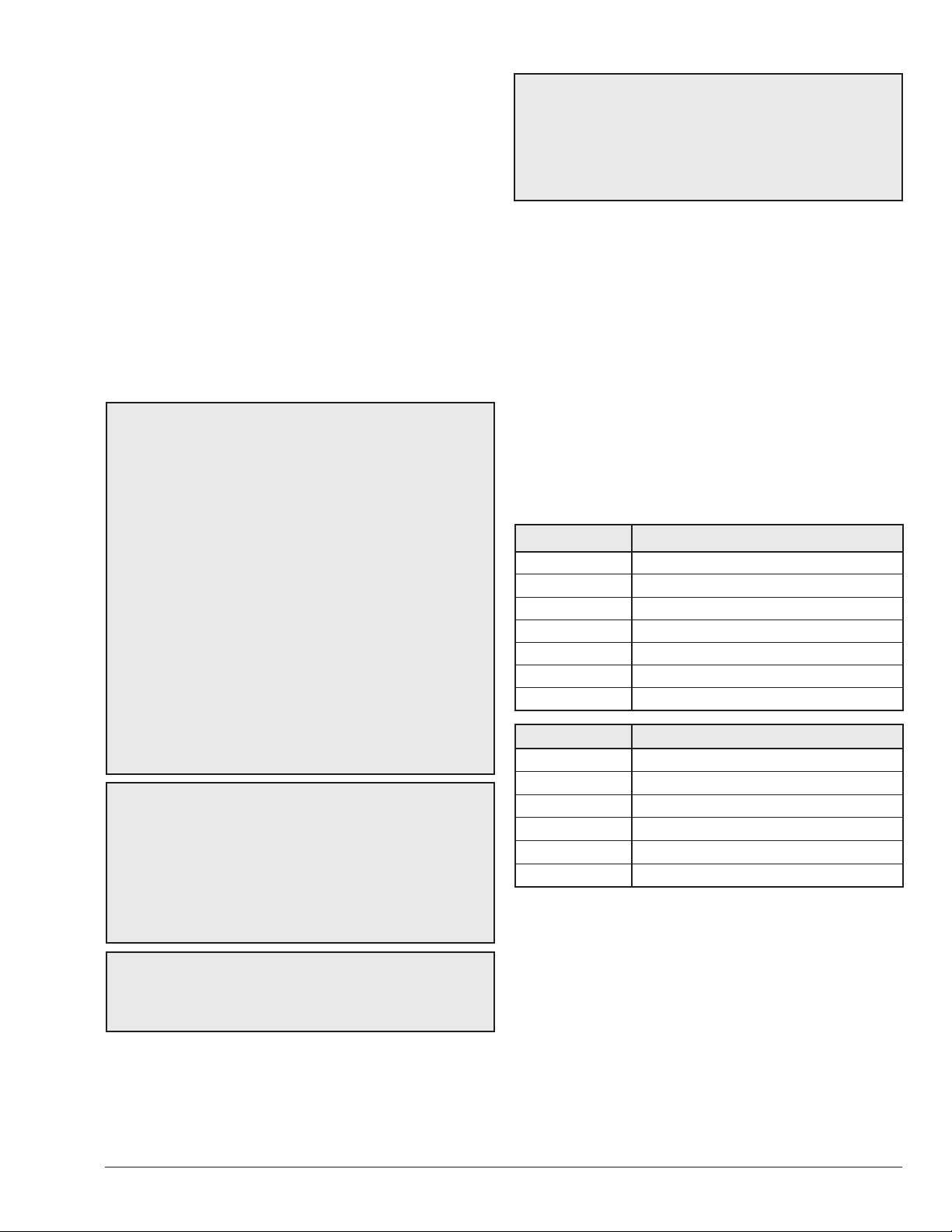
Recommended Level(s) Fiberglass Pools Fiberglass Spas Other Pool and Spa Types
Water Temperature 68-88°F (20-31°C) 89-104°F (31-40°C) 68-104°F (20-40°C)
pH 7.3-7.4 7.3-7.4 7.6-7.8
Total Alkalinity (ppm) 120-150 120-150 80-120
Calcium Hardness (ppm) 200-300 150-200 200-400
Salt (ppm) 4500 Maximum 4500 Maximum 4500 Maximum
Free Chlorine (ppm)* 2-3 2-3 2-3
Total Dissolved Solids (ppm) 3000 Maximum** 3000 Maximum** 3000 Maximum**
*Free Chlorine MUST NOT EXCEED 5 ppm!
**In saltwater chlorinated pools, the total TDS can be as high as 6000 ppm.
Table A. Pool Water Chemistry
5
3. BEFORE INSTALLATION
Be sure that you receive the number of packages indicated
on the Bill of Lading.
Receiving equipment
The manufacturer recommends that this manual be
reviewed thoroughly before installing the pool/spa heater. If
there are any questions that this manual does not answer,
please contact the factory or your local representative.
On receipt of your equipment it is suggested that you
visually check for external damage to the carton. If the
carton is damaged, a note should be made on the Bill
of Lading when signing for the equipment. Remove the
heater from the carton. If it is damaged, report the damage
to the carrier immediately. Save the carton.
These items are shipped inside a box in the carton with
the heater:
Standard Unit (POLYMER HEADERS)
1. “Pagoda” top
2. 2" CPVC union half with "O" rings (2)
3. Plastic pipe finish flange for gas line
4. Bonding lug with mounting screw
ASME Unit (BRASS HEADERS)
1. “Pagoda” top
2. 2" CPVC union half with "O" rings (2)
3. Plastic pipe finish flange for gas line
4. Bonding lug with mounting screw
5. Pressure Relief Valve
6. ProTek Shield Adapter with ProTek Shield Assembly
and wing nut
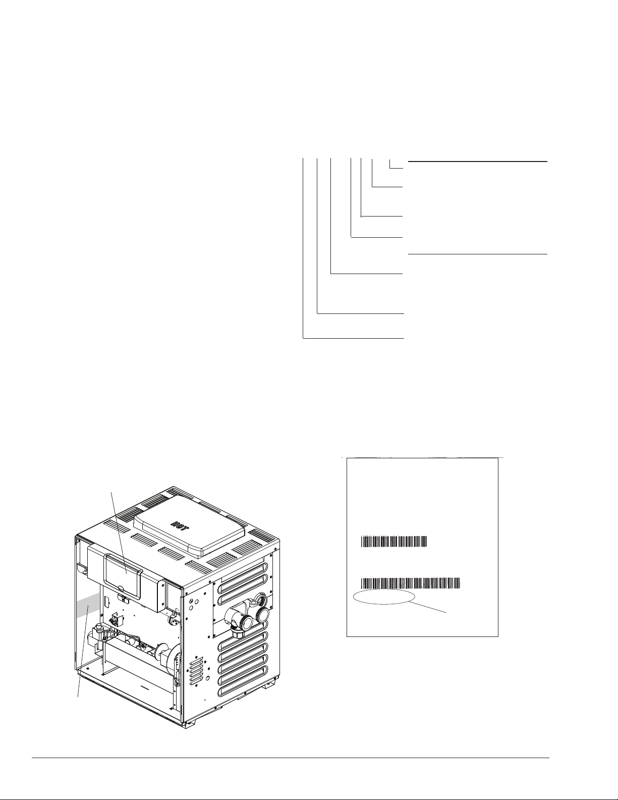
THE MODEL AND SERIAL NO.
CAN ALSO BE FOUND INSIDE
THE BEZEL ABOVE THE DISPLAY
Model Identication Number
The model number of a pool heater can be found on the
Sales Order and the pool heater rating plate. The example
below identies what the characters of the model number
represent.
B - _ 207A - E N - C # 26
#
Burner Orice Size
C Copper tubes
X Cupronickel tubes
N Natural gas
E Electronic ignition
207A input 199,500 BTUH (58.4 kw)
267A input 266,000 BTUH (77.9 kw)
337A input 332,500 BTUH (97.4 kw)
407A input 399,000 BTUH (116.9 kw)
_ Brand designation with letter
B Bronze headers
P Polymer headers
†
For commercial installations, ASME-Certied.
† †
Units with polymer headers do not meet building code requirements for
commercial installations. Consult local code authorities before using any
unit with polymer headers in a commercial environment.
(for residential use ONLY)
†
† †
When ordering parts, you must specify the model and
serial numbers of the heater. See Figure 1 for location of
serial number. When ordering under warranty conditions,
you must also specify date of installation.
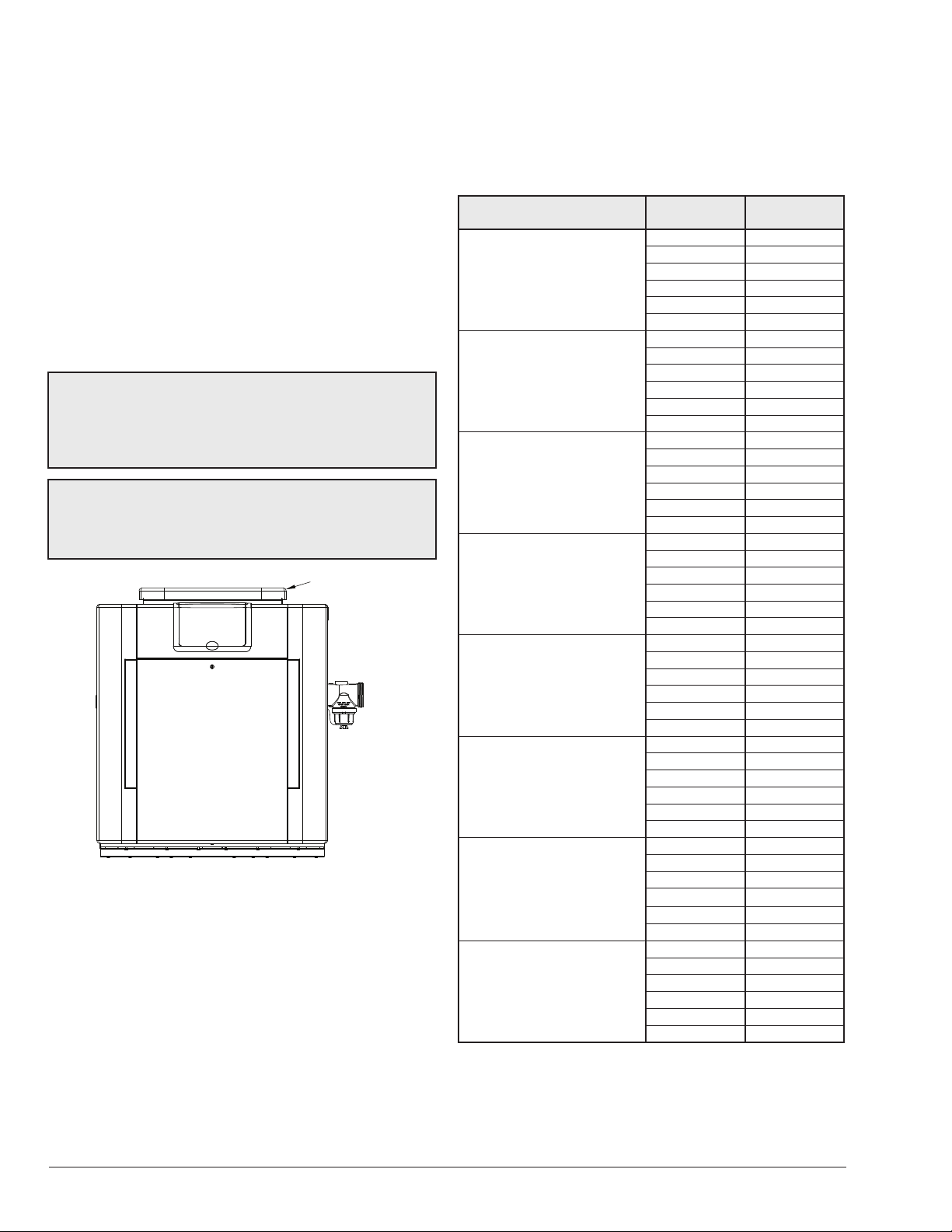
Model:
P-R 207A-EN-C #26
POLYMER
Fuel: Ignition
NAT IID
Item Number:
MODEL AND SERIAL NO.
LOCATED ON RATING PLATE
Figure 1. Rating Plate Location
6
F10639-1
009240
Serial Number:
91001010
Note:
Figure 2. Model and Serial Number
Rating and certications
These heaters are design-certied and tested under the
latest requirements of the ANSI Z21.56 / CSA 4.7 Standard
for Gas-Fired Pool Heaters. All heaters can be used either
indoor or outdoors when appropriate venting is installed.
The appropriate top designated for each type of use is
Serial No.
required. If necessary, the top can be changed at a later
date to change from outdoor to indoor or vice versa.
Elevation
Rated inputs are suitable for up to 5,000 feet (1524 m)
elevation. For elevations above 5,000 feet (1524 m),
consult the factory.
Ambient Temperature Rating
Heater Components
Electronic Ignition Heater* -32°F to 175°F (-35°C to 79°C)
*Requires 120 or 240VAC, 1 Ph, 60 Hz Power Supply
4. INSTALLATION
WARNING: This unit contains refractory ceramic
AA
ber (RCF) insulation in the combustion chamber. RCF,
as manufactured, does not contain respirable crystalline
silica. However, following sustained exposure to very
high temperatures (>2192°F), the RCF can transform
into crystalline silica (cristabolite). The International
Agency for Research on Cancer (IARC) has classied
the inhalation of crystalline silica (cristabolite) as
carcinogenic to humans.
When removing the burners or heat exchangers, take
precautions to avoid creating airborne dust and avoid
inhaling airborne bers. When cleaning spills, use wet
sweeping or High Eciency Particulate Air (HEPA)
ltered vacuum to minimize airborne dust. Use feasible
engineering controls such as local exhaust ventilation
or dust collecting systems to minimize airborne dust.
Wear appropriate personal protective equipment
including gloves, safety glasses with side shields, and
appropriate NIOSH certied respiratory protection,
to avoid inhalation of airborne dust and airborne ber
particles.
IMPORTANT NOTICE: These instructions are intended
only for the use by qualied personnel, specically
trained and experienced in the installation of this type
of heating equipment and related system components.
Installation and service personnel may be required by
some states to be licensed. If your state is such, be sure
your contractor bears the appropriate license. Persons
not qualied shall not attempt to x the equipment nor
attempt repairs according to these instructions.
WARNING: Improper installation, adjustment,
AA
alteration, service or maintenance may damage the
equipment, create a hazard resulting in asphyxiation,
explosion or re, and will void the warranty.
NOTE: The heater should not be located in an area where
possible water leakage will result in damage to the area
adjacent to the heater or to the structure. When such
locations cannot be avoided, it is recommended that a
suitable drain pan, with adequate drainage, be installed
under the heater. The pan must not restrict combustion
air ow.
Installation Codes
Installation must be in accordance with local codes, or,
in the absence of local codes, with the latest edition of
the National Fuel Gas Code, ANSI Z223.1/NFPA54 and
National Electrical Code, ANSI/NFPA 70, and for Canada,
the latest edition of CAN/CSA-B149 Installation Codes,
and Canadian Electrical Code, CSA C22.1 Part 1 and
Part 2.
Clearances
All Heaters
For indoor and outdoor clearances from combustible
surfaces, see the chart below.
Location Indoor Installation
Top * 30" (762 mm) Drafthood
Front Alcove (Open)
Vent 6" (152 mm)
Floor ** 0"
Back 6" (152 mm)
Right Side 12" (305 mm) Water Side
Left Side 6" (152 mm) Opposite Water Side
Location Outdoor Installation
Top * Unobstructed (Outdoor Stack)
Top *** 36" (914 mm) (Stackless Top)
Floor 0"
Back 6" (152 mm)
Right Side 12" (305 mm) Water Side
Left Side 6" (152 mm) Opposite Water Side
* Clearance from top of vent terminal
** Do not install on carpeting
*** Clearance from top of heater
Table B. Minimum Clearances from Combustible Surfaces
When installed according to the listed minimum clearances
from combustible construction, the pool heater can still be
serviced without removing permanent construction around
the heater.
However for ease of servicing, we recommend a clearance
of at least 24" (610 mm) in the front, and at least 18"
(457 mm) on the water connection side. This will enable
the heater to be serviced in its installed location, that is,
without movement or removal of the heater.
7
Clearances less than these may require removal of the
heater to service either the heat exchanger or the burner
tray. In either case, the heater must be installed in a manner
that will enable the heater to be serviced without removing
any structure around the heater.
Flooring
This heater can be installed on combustible ooring. The
combustible clearances listed can be reduced by protecting
the exposed combustible surfaces as shown in Table C.
Outdoor Heater Installation
These heaters are design-certied for outdoor installation,
when equipped with the approved tops designated for
outdoor use.
WARNING: The heater shall not be located in an
AA
area where water sprinklers, or other devices, may cause
water to spray through the cabinet louvers and into the
heater. This could cause internal rusting or damage
electrical components, and void the warranty.
WARNING: Do not install within 3' (0.9 m) of a heat
AA
pump or an outdoor condensing unit. Strong air intake
from this type of equipment can disturb the combustion
process and cause damage or personal injury.
PAGODA TOP
INSTALLATION
F10647-2
Figure 3. Heater with Outdoor Stackless Top
Heaters must not be installed under an overhang of less
than three 3' (0.9 m) from the top of the heater. Three sides
must be open in the area under the overhang. Roof water
drainage must be diverted away from the heaters installed
under overhangs with the use of gutters.
For U.S. installations, the point from where the ue
products exit the heater must be a minimum of 4' (1.2 m)
below, 4' (1.2 m) horizontally from, or 1' (0.3 m) above any
door, window or gravity inlet into any building. The top
surface of the heater shall be at least 3' (0.9 m) above
any forced air inlet, or intake ducts located within 10' (3 m)
horizontally.
For Canadian installations, pool heaters shall not be
installed with the top of the vent assembly within 10' (3 m)
below, or to either side, of any opening into the building.
Refer to the latest revisions of CAN/CSA-B149.
A minimum of 6' (1.8 m) is required from the heater to an
inside corner wall for proper outdoor venting.
Description Location
Back 9 (229)
a. 3-1/2" (89 mm) thick
masonry walls without
ventilated air space
b. 1/2" (13 mm)insulation
board over 1" (25 mm)
glass ber or mineral
wool batts
c. 0.024 sheet metal over
1" (25 mm) glass ber
or mineral wool batts
reinforced with wire on
rear face with ventilated
air space
d. 3-1/2" (89 mm) thick
masonry wall with
ventilated air space
e. 0.024 sheet metal with
ventilated air space
f. 1/2" (13 mm) thick
insulation board with
ventilated air space
g. 0.024 sheet metal with
ventilated air space over
0.024 sheet metal with
ventilated air space.
h. 1" (25 mm) glass ber
or mineral wool batts
sandwiched between two
sheets 0.024 sheet metal
with ventilated air space
Derived from National Fuel Gas Code, Table 10.2.3
Table C. Reduction of Clearances to Protected Surfaces
Right 9 (229)
Left 9 (229)
Vent 5 (127)
Indoor Top 39 (991)
Outdoor Top Unobstructed
Back 6 (152)
Right 6 (152)
Left 6 (152)
Vent 3 (76)
Indoor Top 30 (762)
Outdoor Top Unobstructed
Back 4 (102)
Right 4 (102)
Left 4 (102)
Vent 3 (76)
Indoor Top 24 (610)
Outdoor Top Unobstructed
Back 6 (152)
Right 6 (152)
Left 6 (152)
Vent 6 (152)
Indoor Top 39 (991)
Outdoor Top Unobstructed
Back 4 (102)
Right 4 (102)
Left 4 (102)
Vent 2 (51)
Indoor Top 24 (610)
Outdoor Top Unobstructed
Back 4 (102)
Right 4 (102)
Left 4 (102)
Vent 3 (76)
Indoor Top 24 (610)
Outdoor Top Unobstructed
Back 4 (102)
Right 4 (102)
Left 4 (102)
Vent 3 (76)
Indoor Top 24 (610)
Outdoor Top Unobstructed
Back 4 (102)
Right 4 (102)
Left 4 (102)
Vent 3 (76)
Indoor Top 24 (610)
Outdoor Top Unobstructed
Distance
in. (mm)
8
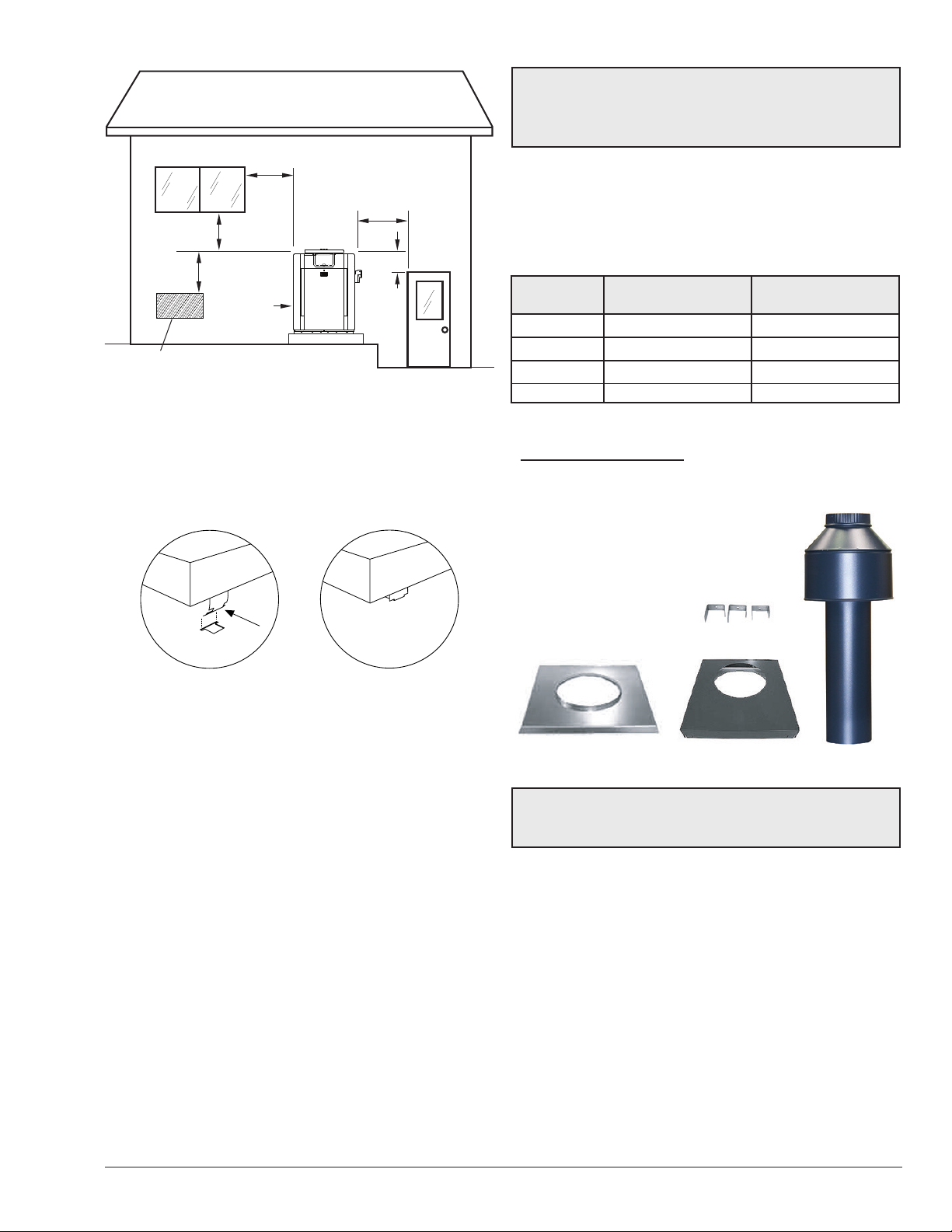
4' (1.2 m)
Minimum
4' (1.2 m)
Minimum
4' (1.2 m)
Minimum
3' (0.9 m)
Minimum
10' (3 m)
Minimum
Forced Air Inlet
Figure 4. Clearances
1' (0.3 m)
Minimum
Pagoda Top Installation
1. Insert tabs into keyhole (4 places). See Figure 5,
detail A.
2. Snap tabs into keyholes so as not to pull out. See
Figure 5, detail B.
WARNING: Indoor heaters require a drafthood that
AA
must be connected to a vent pipe and properly vented to
the outside. Failure to follow this procedure can cause
re or fatal carbon monoxide poisoning.
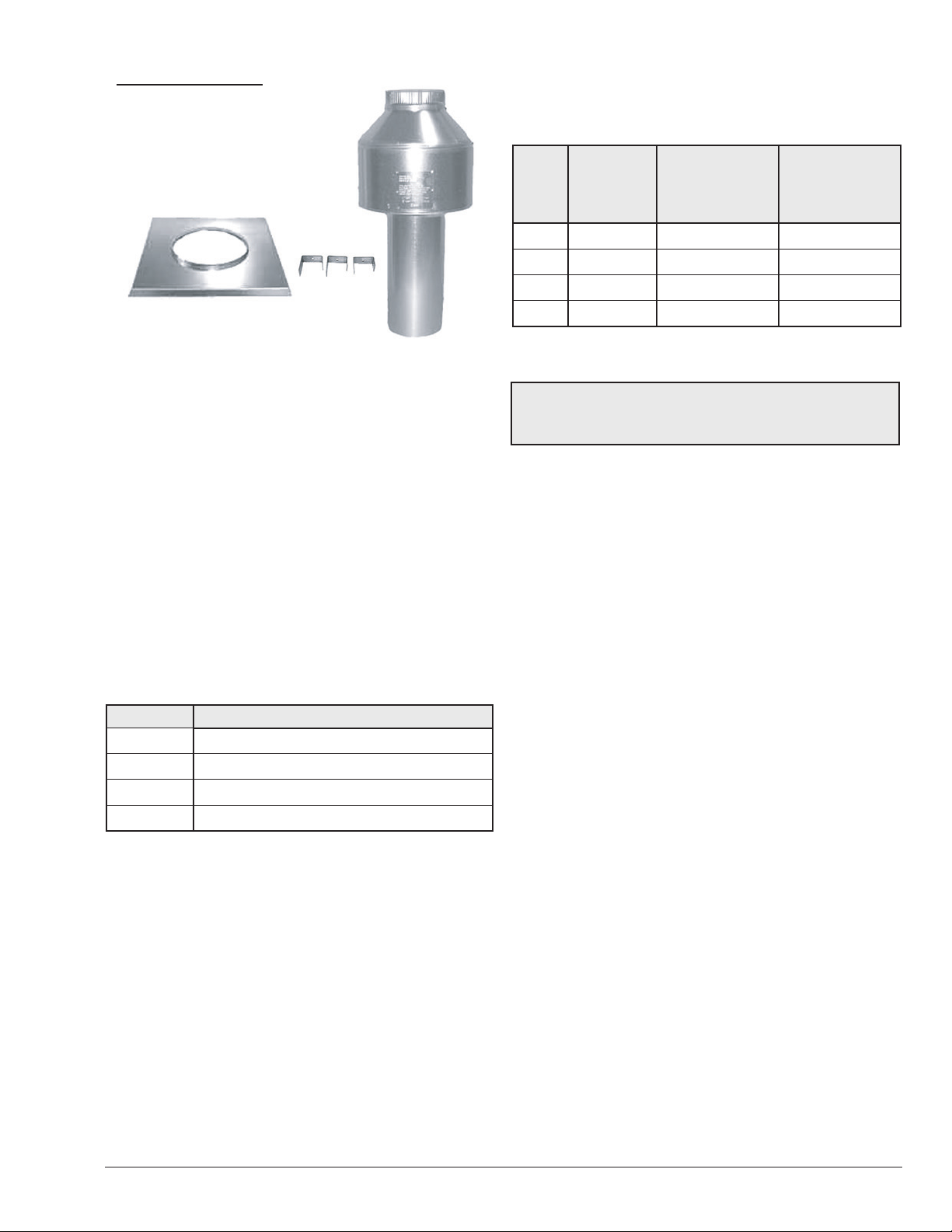
Outdoor and Indoor Stacks
The outdoor and indoor stacks are optional equipment
and do not come standard with the heater. Refer to
installation instructions inside box for instructions on
how to install outdoor/indoor stack.
Outdoor Stack Indoor Stack
Model Part No Part No.
207A 009834 009838
267A 009835 009839
337A 009836 009840
407A 009837 009841
Table D. Outdoor and Indoor Stack Kit Number
OUTDOOR STACK KIT
(1) Outdoor stack, painted
(1) Adapter plate
(3) Mounting brackets (clips)
(1) Top panel cover
(2) 1-foot sections of metal tape
(3) Screws
(1) Instructions
Clips
DETAIL A DETAIL B
OUTDOOR TOP
(SHIPPED LOOSE WITH HEATER)
Figure 5. Outdoor Top Installation
For installations in Florida and Texas, that must
comply with the Florida or Texas Building Code, follow
the directions shown in Figure 7 for the installation of
hurricane tie-down brackets for all models.
Indoor Heater Installation
The heater is also design-certied for indoor installation
when equipped with the approved drafthood.
For Canada, indoor installation is restricted to an enclosure
that is not occupied and does not directly communicate
with an occupied area. Refer to the latest edition of CAN/
CSA-B149 for specic requirements. Locate heater as
close as is practical to a chimney or gas vent. Heater
must always be vented to the outside. See section "Vent
Piping" on page 13 for details. Minimum allowable
space is shown on the nameplate.
Figure 6. Outdoor Stack Kit Components
NOTE: The outdoor drafthood kit does not require any
additional vent pipe for proper operation. This drafthood
functions as the vent termination.
9
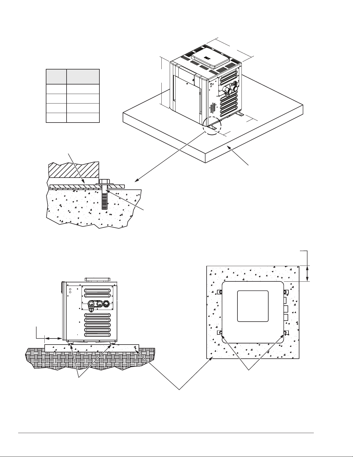
Florida and Texas Building Code:
Wind Speed = 150 mph 3 sec gust
Exposure = C
B
Model
B
in. (mm)
207A 20 (508)
267A 23 (584)
337A 26 (660)
407A 29 (737)
2" x 6" x 1/8" Pallet
Anchor Bracket (4 Total) (Kit# 011636)
31-13/16"
(792 mm)
F10649
28"
(709 mm)
3" (76 mm)
Min. Conc.
Pad by others
1/4" x 1-3/4" S.S.
Tapcon Bolt and Washer (Field-Supplied)
NOTE: Use hole closest to unit with
washer overlapping edge of unit.
Min. Edge
Distance
6"
(152 mm)
Min. Edge
Distance
6"
(152 mm)
(1)–1/4" x 1-3/4" S.S. Tapcon
Bolt & Washer (Field-Supplied)
Ea. Pallet Anchor Bracket
Use hole closest to unit (4 total)
10
(1)–1/4" x 1-3/4" S.S.
Tapcon Bolt & Washer (Field-Supplied)
Ea. Pallet Anchor Bracket
3" (76 mm)
Min. Conc.
Pad by others
Use hole closest to unit (4 total)
Figure 7. Hurricane Tie-Down Bracket Installation
TOH
INDOOR STACK KIT
(1) Drafthood, unpainted
(1) Adapter plate
(3) Mounting brackets (clips)
(3) Screws
(1) Instructions
Clips
All Air from Outdoors:
When air is supplied directly from outside the building, each
opening shall have a minimum net free area as noted:
Unrestricted
Model
207A 50 (0.03) 75 (0.05) 100 (0.1)
267A 67 (0.04) 101 (0.06) 134 (0.09)
337A 84 (0.05) 126 (0.08)
407A 100 (0.06) 150 (0.1)
Opening
sq. in. (m2)
Typical Screened
or Louvered
Opening
sq. in. (m2)
Typical Screened
and Louvered
Opening
sq. in. (m2)
168 (0.11)
200 (0.13)
Figure 8. Indoor Stack Kit Components
Combustion and Ventilation Air
Indoor Units Only
The heater must have both combustion and ventilation
air. The minimum requirements are listed in the latest
edition of the National Fuel Gas Code (U.S. ANSI Z223.1
or Canada CAN/CSA-B149) and any local codes that
may have jurisdiction. The most common approach is
the "2-opening" method, with combustion air opening no
more than 12" from the oor and the ventilation opening
no more than 12" from the ceiling. For opening sizes using
this method, see below.
All Air from Inside the Building:
Each opening shall have a minimum net free area as
noted:
Model Sq. in. (m2)
207A 200 (0.13)
267A 266 (0.17)
337A 333 (0.21)
407A 399 (0.26)
Table F. Opening Minimum Net Free Requirements -
Outdoor Air
CAUTION: Combustion air must not be contaminated
AA
by corrosive chemical fumes which can damage the
heater. Such damage will not be covered by the warranty
Table E. Opening Minimum Net Free Requirements -
Indoor Air
11
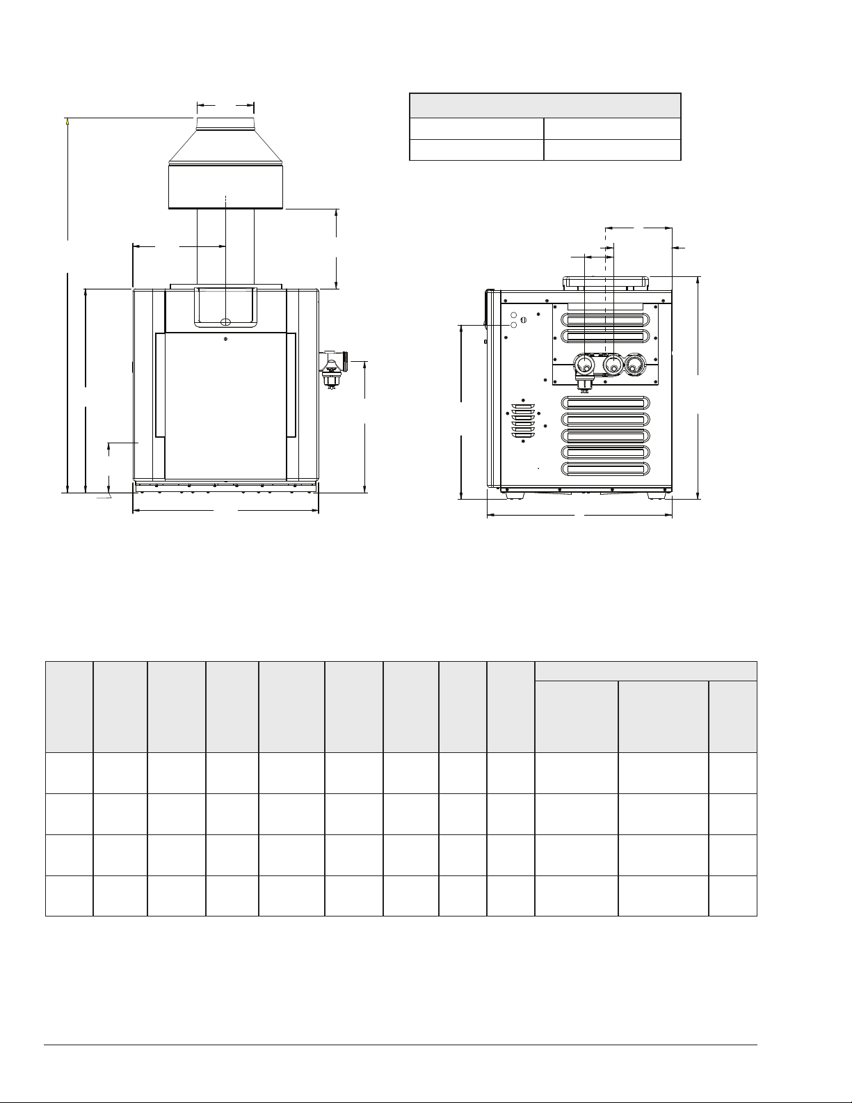
Specications and Dimensions
(711 mm)
F10647-1
C
L
FLUE
C
INDOOR
DRAFTHOOD
31-13/16"
(792 mm)
GAS
CONNECTION
7-3/4"
(197 mm)
B
Amp Draw
120 VAC, 1 Ph, 60 Hz 240 VAC, 1 Ph, 60 Hz
6 3
10"
(254 mm)
J*D
20-1/2"
(521 mm)
A
F10647
26-1/2"
(673 mm)
ELECTRICAL
CONNECTION
4-3/8"
(111 mm)
28"
8-7/8"
(225 mm)
(6-5/8" ASME)
(168 mm ASME)
34"
(867 mm)
STACKLESS
OUTDOOR
TOP
Figure 9. Front View
*Note: For outdoor stack, use J dimension in the table below for appropriate size plus 6" (152 mm).
Heater
Model
R207A
R267A
R337A
R407A
BTUH
Input
(000)
(kw)
199.5
(58.4)
266.0
(77.9)
332.5
(97.4)
399
(116.9)
(A)
Cabinet
Width
in. (mm)
20
(508)
23
(584)
26
(660)
29
(737)
(B)
Flue
Dia.
in.
6
7
8
9
(C)
Indoor
Drafthood
in. (mm)
55-5/8
(1413)
56
(1422)
57
(1448)
58-1/2
(1486)
(D)
in. (mm)
10.0
(254)
11.5
(292)
13.0
(330)
14.5
(368)
(J)*
Min.
in. (mm)
11-3/4
(298)
11
(279)
10-5/8
(270)
12-1/2
(318)
Gas
Conn.
in.
3/4 2
3/4 2
3/4 2
3/4 2
Water
Conn.
in.
Table G. Heater Specications and Dimensions
Figure 10. Side View
Shipping Weights - lbs (kg)
Standard
Heater
w/Stackless
w/Stackless
Top
174
(79)
197
(89)
219
(99)
237
(108)
ASME
Heater
Top
193
(88)
216
(98)
238
(108)
256
(116)
Indoor
Draft-
hood
14
(6.4)
16
(7.3)
19
(8.6)
21
(9.5)
12
Vent Piping
WARNING: Indoor heaters require a drafthood that
AA
must be connected to a vent pipe and properly vented to
the outside. Failure to follow this procedure can cause
re or fatal carbon monoxide poisoning.
When properly installed outdoors, only the outdoor
stackless top, provided, is required. If installed indoors,
a drafthood is required, connected to a CATEGORY
I (a heater that operates with a non-positive vent static
pressure and a vent gas temperature that avoids excessive
condensate production in the vent) vent per the National
Fuel Gas Code and local requirements.
Vent piping the same size as the drafthood outlet is
recommended, however, when the total vent height is at
least 10 ft (3 m) (drafthood relief opening to vent terminal),
the vent pipe size may be reduced by no more than one
size as specied in Chapter 13 of the National Fuel Gas
Code, ANSI Z223.1 (Canada - CAN/CSA-B149).
As much as possible, avoid long horizontal runs of vent
pipe and too many elbows. If installation requires horizontal
runs, the vent pipe must have a minimum of 1/4 in. per ft
rise (20.8 mm per meter rise) and should be supported at
not more than 5 ft (1.5 m) intervals.
maintained. However single-wall metal vent pipe may be
used as specied in the latest edition of the National Flue
Gas Code, ANSI Z223.1 (Canada - CAN/CSA-B149).
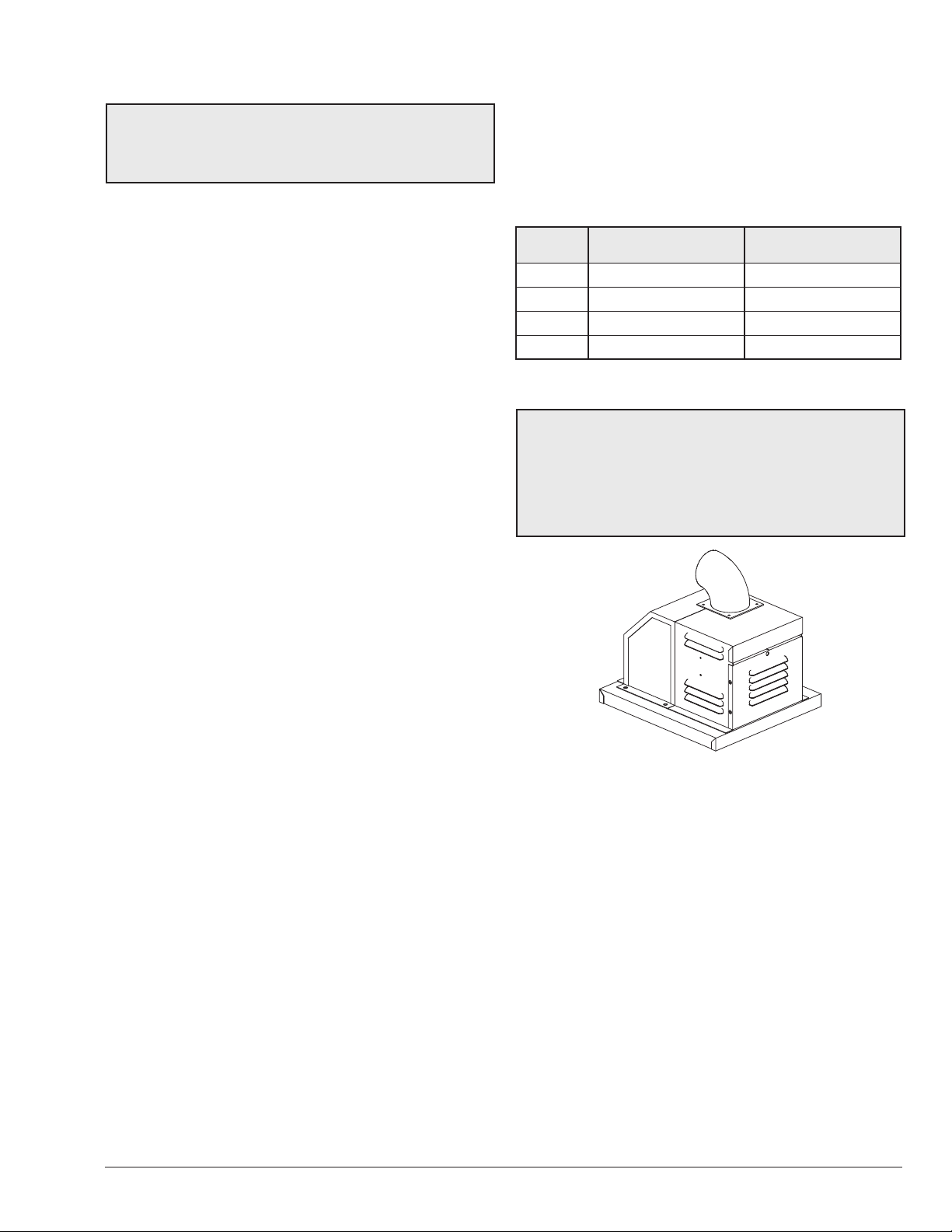
D-2 Power Vent Kit
Another option for an installation that requires horizontal
runs is using the D-2 power vent kit option.
Model 120 VAC P/N 240 VAC P/N
207A 010744 009832
267A 010744 009832
337A 010745 009833
407A 010745 009833
Table H. Power Vent Kit Part Numbers
NOTE: The D-2 Power Vent operates with a positive
vent static pressure and with a vent gas temperature
that prevents excessive condensate production in the
vent, and as such, is a CATEGORY III appliance. For
more information consult the D-2 Power Vent manual
6000.57.1. CATEGORY I vent material such as B-vent
must not be used under CATEGORY III conditions.
Plumber's tape, criss-crossed, will serve to space both
horizontal and vertical piping. Gas vents supported only
by the ashing and extending above the roof more than 5
ft (1.5 m) should be securely guyed or braced to withstand
snow and wind loads. We recommend use of insulated
vent pipe spacers through the roof and walls.
For protection against rain or blockage by snow, the vent
pipe must terminate with a vent cap which complies with
the local codes or, in the absence of such codes, to the
latest edition of the National Fuel Gas Code, ANSI Z223.1
(Canada - CAN/CSA-B149).
The discharge opening must be a minimum of 2' (0.6
m) vertically from the roof surface and at least 2' (0.6 m)
higher than any part of the building within 8' (2.4 m). Vent
stack shall be at least 5' (1.5 m) in vertical height above
the drafthood outlet. The vent cap location shall have a
minimum clearance of 4' (1.2 m) horizontally from, and in
no case below, unless a 4' (1.2 m) horizontal distance is
maintained, from electric meters, gas meters, regulators
and relief equipment.
The weight of the vent stack or chimney must not rest on the
heater drafthood. Support must be provided in compliance
with applicable codes. The heater top and drafthood must
be readily removable for maintenance and inspection.
Vent pipe should be adequately supported to maintain
proper clearances from combustible construction.
Flue materials must be certied to CATEGORY I or
better. Type “B” double-wall or equivalent vent pipe is
recommended. A draft of -0.01" to -0.08" WC must be
Figure 11. D-2 Power Vent Option
The power vent system is a fan-assisted combustion
system designed for application to models 207A-407A.
The power vent system, when installed as directed, is
capable of operating in applications such as through-thewall venting with reduced horizontal and vertical vent pipe
sizes in new and current installations. The unit is factorywired for 240 VAC, with capability of eld-rewiring for 120
VAC.
For more information consult the D-2 Power Vent manual,
(Catalog No. 6000.57.1).
13
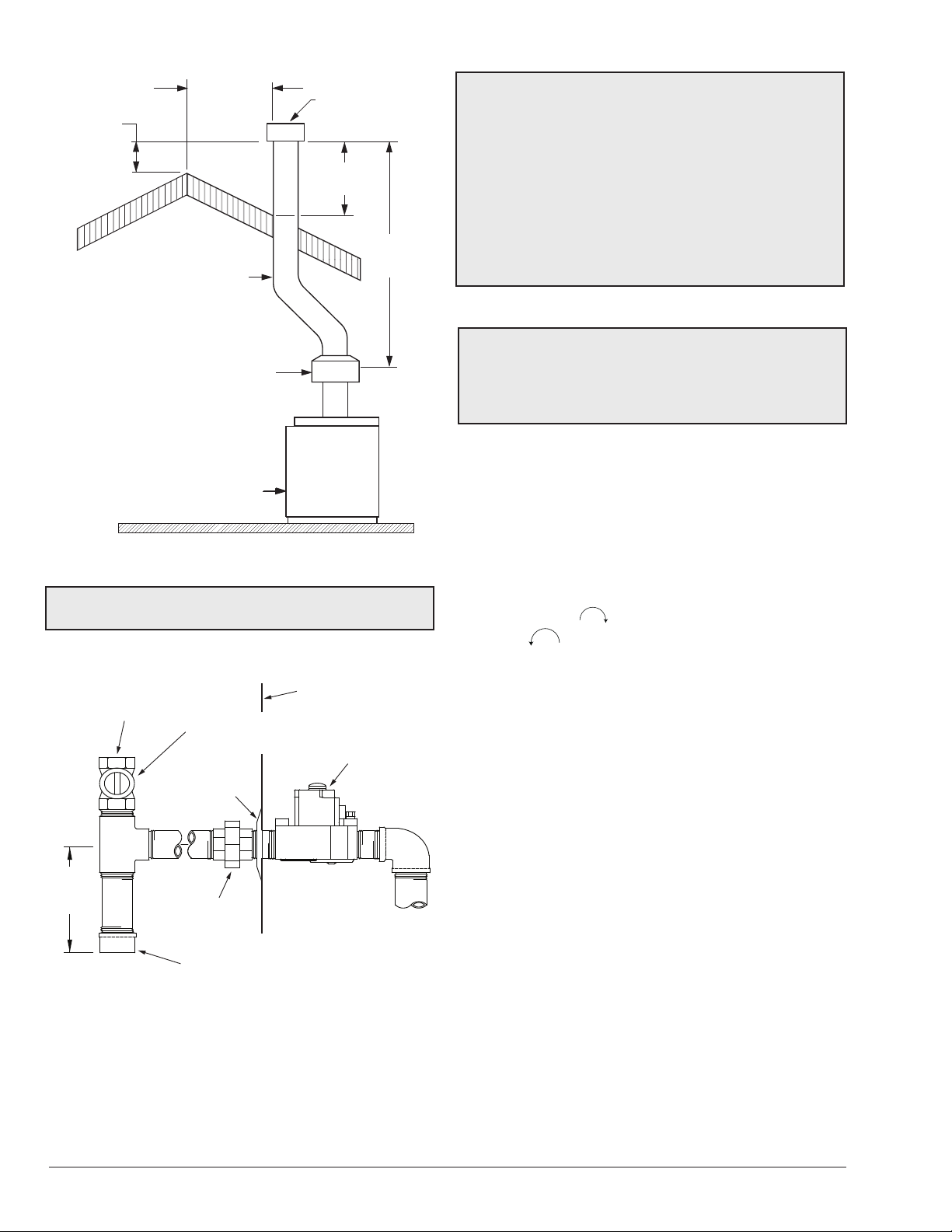
8' (2.4 m)
OR LESS
HEATER JACKET
2' MIN
(0.6 m)
VENT PIPE
DRAFT HOOD
HEATER
VENT CAP
2' MIN
(0.6 m)
5' MIN
(1.5 m)
Figure 12. Venting Clearances
NOTE: With venting application of two or more heaters,
contact the factory.
CAUTION: The heater and its manual shut-o valve
AA
must be disconnected from the gas supply during any
pressure testing of that system at test pressures in
excess of 1/2 psi (3.45 kPa). Dissipate test pressure in
the gas supply line before reconnecting the heater and
its manual shut o valve to gas supply line. FAILURE
TO FOLLOW THIS PROCEDURE MAY DAMAGE THE
GAS VALVE. OVER PRESSURIZED GAS VALVES ARE
NOT COVERED BY WARRANTY. The heater and its gas
connections shall be leak tested before placing the
appliance in operation. Use soapy water for leak test. DO
NOT use open ame.
Supply Pressure
CAUTION: Do not use teon tape on gas line pipe
AA
thread. Only sealant tape or a pipe compound rated for
use with natural and propane gases is recommended.
Apply sparingly only on male pipe ends, leaving the two
end threads bare.
A minimum of 5 in. WC and a maximum of 10.5 in. WC
upstream pressure under load and no-load conditions
must be provided for natural gas.
Gas Pressure Regulator
The gas pressure regulator is preset at 3.1 in. WC for
natural gas. The pressure at the gas valve, taken with a
manometer, should be about 3.1 in. WC natural gas. If an
adjustment is needed, remove seal and turn adjustment
screw clockwise
clockwise to decrease pressure.
to increase pressure or counter-
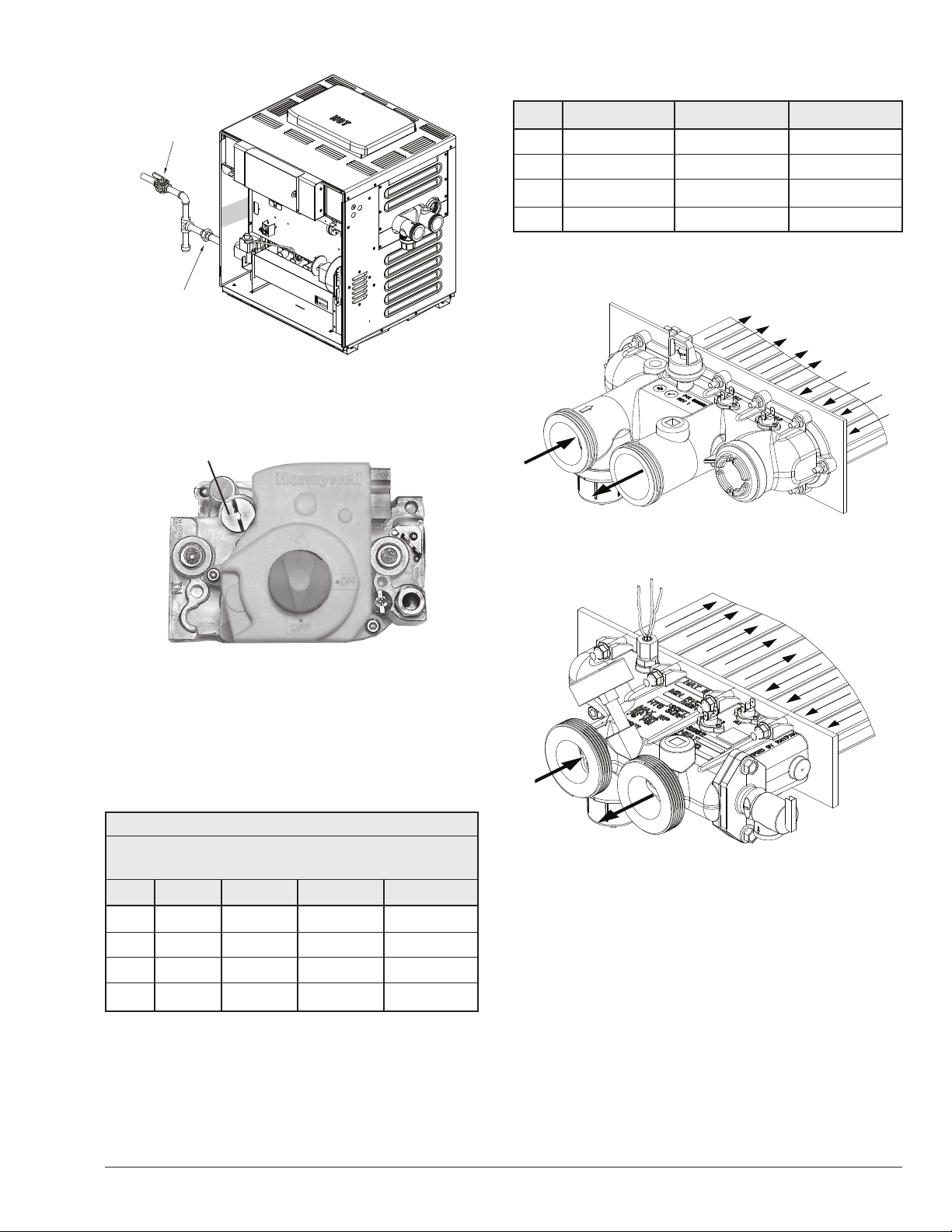
Gas Supply Connections
GAS INLET
3" MIN
(76 mm)
Typical
Figure 13. Gas Supply Plumbing
Gas piping must have a sediment trap ahead of the
heater gas controls, and a manual shut-o valve located
outside the heater jacket. All gas piping should be tested
after installation in accordance with local codes.
MANUAL SHUT-OFF VALVE
FINISH FLANGE
UNION
(Field supplied)
SEDIMENT TRAP
(Field supplied)
(Field supplied)
GAS VALVE
14
MANUAL
F10638-1
SHUT-OFF
VALV E
UNION
F10639-4
Figure 14. Manual Shut-O Valve Installation
Gas Pressure Adjustment Locations
Gas Pressure Adjustment
Flow Rates
Model Pipe Size Min. GPM (lpm) Max. GPM (lpm)
207A 1-1/4"–1-1/2"–2" 20 (75) 125 (473)
267A 1-1/4"–1-1/2"–2" 25 (95) 125 (473)
337A 1-1/4"–1-1/2"–2" 35 (132) 125 (473)
407A 1-1/4"–1-1/2"–2" 40 (151) 125 (473)
* When ow rates exceed maximum GPM an external auxiliary bypass valve is
required. See external bypass valve section for details.
Table J. Min/Max Flow Rates
Figure 15. Honeywell VR8340)
Pipe Sizing for Gas Connection
The capacities shown below are based on using SCH
40 black iron pipe. For capacities using other materials,
consult local codes.
Maximum Equivalent Pipe Length (ft) (m)
3
Natural Gas 1000 BTU/FT
in. WC Pressure Drop
Model 3/4" 1" 1-1/4" 1-1/2"
207A 25 (7.6) 90 (27.4) 360 (109.7) n/a
267A 15 (4.6) 50 (15.2) 210 (64.0) 445 (135.6)
337A 10 (3.0) 30 (9.1) 140 (42.7) 290 (88.4)
0.60 Specic Gravity @ 0.5
Figure 16. Polymer Headers Water Flow
F10637-1
Figure 17. Brass Headers (ASME) Water Flow
407A * 20 (6.1) 95 (29.0) 215 (65.5)
* A 3/4" gas line can be used for up to 5' (1.5 m) maximum length from the gas
valve in addition to the sediment trap.
Table I. Gas Pipe Sizing
15
 Loading...