

Page 1

10 & 12.5 TON
15 & 20 TON
INSTALLATION INSTRUCTIONS
Recognize this symbol as an indication of Important Safety Information!
!
DO NOT DESTROY. PLEASE READ CAREFULLY AND
KEEP IN A SAFE PLACE FOR FUTURE REFERENCE.
!
WARNING
THESE INSTRUCTIONS ARE INTENDED AS AN AID TO
QUALIFIED, LICENSED SERVICE PERSONNEL FOR PROPER
INSTALLATION, ADJUSTMENT AND OPERATION OF THIS UNIT.
READ THESE INSTRUCTIONS THOROUGHLY BEFORE
ATTEMPTING INSTALLATION OR OPERATION. FAILURE TO
FOLLOW THESE INSTRUCTIONS MAY RESULT IN IMPROPER
INSTALLATION, ADJUSTMENT, SERVICE OR MAINTENANCE
POSSIBLY R E S U L T I N G IN F I R E , ELECTRICAL S H O C K ,
PERSONAL INJURY OR PROPERTY DAMAGE.
RAWL HIGH EFFICIENCY R-410A COMMERCIAL CONDENSING UNITS
NOMINAL SIZES 10, 12.5, 15 & 20 TONS
SUPERSEDES 92-42665-11-00
92-42665-11-01
Page 2
TABLE OF CONTENTS
IMPORTANT: TO INSURE PROPER INSTALLATION AND OPERATION OF
THIS PRODUCT, COMPLETELY READ ALL INSTRUCTIONS PRIOR TO
ATTEMPTING TO ASSEMBLE, INSTALL, OPERATE, MAINTAIN OR REPAIR
THIS PRODUCT. IMMEDIATELY UPON RECEIPT, ALL CARTONS AND
CONTENTS SHOULD BE INSPECTED FOR TRANSIT DAMAGE. UNITS WITH
DAMAGED CARTONS SHOULD BE OPENED IMMEDIATELY. IF DAMAGE IS
FOUND, IT SHOULD BE NOTED ON THE DELIVERY PAPERS AND A
DAMAGE CLAIM FILED WITH THE LAST CARRIER.
IMPORTANT MESSAGE TO OWNER . . . . . . . . . . . . . . . . . . . . . . . . . . . . . . . . . . . . . . 4
CHECKING PRODUCT RECEIVED . . . . . . . . . . . . . . . . . . . . . . . . . . . . . . . . . . . . . . . . 4
ENERAL . . . . . . . . . . . . . . . . . . . . . . . . . . . . . . . . . . . . . . . . . . . . . . . . . . . . . . . . . . . . 4
G
STANDARD UNIT FEATURES . . . . . . . . . . . . . . . . . . . . . . . . . . . . . . . . . . . . . . . . . . . . 4
INSTALLATION . . . . . . . . . . . . . . . . . . . . . . . . . . . . . . . . . . . . . . . . . . . . . . . . . . . . . . . 10
Crankcase Heaters. . . . . . . . . . . . . . . . . . . . . . . . . . . . . . . . . . . . . . . . . . . . . . . . . . . . . 10
Corrosive Environment. . . . . . . . . . . . . . . . . . . . . . . . . . . . . . . . . . . . . . . . . . . . . . . . . . 10
Installation General . . . . . . . . . . . . . . . . . . . . . . . . . . . . . . . . . . . . . . . . . . . . . . . . . . . . 11
Rooftop Installation. . . . . . . . . . . . . . . . . . . . . . . . . . . . . . . . . . . . . . . . . . . . . . . . . . . . . 11
Slab Installation . . . . . . . . . . . . . . . . . . . . . . . . . . . . . . . . . . . . . . . . . . . . . . . . . . . . . . . 12
INSTALLATION OF PIPING . . . . . . . . . . . . . . . . . . . . . . . . . . . . . . . . . . . . . . . . . . . . . 13
YPICAL PIPING RECOMMENDATIONS . . . . . . . . . . . . . . . . . . . . . . . . . . . . . . . . 13-14
T
ELECTRICAL WIRING . . . . . . . . . . . . . . . . . . . . . . . . . . . . . . . . . . . . . . . . . . . . . . . . . 15
Electrical Power . . . . . . . . . . . . . . . . . . . . . . . . . . . . . . . . . . . . . . . . . . . . . . . . . . . . . . . 15
Power Wiring . . . . . . . . . . . . . . . . . . . . . . . . . . . . . . . . . . . . . . . . . . . . . . . . . . . . . . . . . 15
Wire Routing. . . . . . . . . . . . . . . . . . . . . . . . . . . . . . . . . . . . . . . . . . . . . . . . . . . . . . . . . . 16
Grounding. . . . . . . . . . . . . . . . . . . . . . . . . . . . . . . . . . . . . . . . . . . . . . . . . . . . . . . . . . . . 16
Thermostat . . . . . . . . . . . . . . . . . . . . . . . . . . . . . . . . . . . . . . . . . . . . . . . . . . . . . . . . . . . 16
TOOLS REQUIRED FOR INSTALLING & SERVICING R-410A MODELS . . . . . . . . . 17
SPECIFICATION OF R-410A . . . . . . . . . . . . . . . . . . . . . . . . . . . . . . . . . . . . . . . . . . . . 18
QUICK REFERENCE GUIDE FOR R-410A . . . . . . . . . . . . . . . . . . . . . . . . . . . . . . . . . 18
REPLACEMENT UNITS . . . . . . . . . . . . . . . . . . . . . . . . . . . . . . . . . . . . . . . . . . . . . . . . 18
EVAPORATOR COIL . . . . . . . . . . . . . . . . . . . . . . . . . . . . . . . . . . . . . . . . . . . . . . . . . . 19
LEAK TESTING . . . . . . . . . . . . . . . . . . . . . . . . . . . . . . . . . . . . . . . . . . . . . . . . . . . . . . . 19
EVACUATION AND CHARGING . . . . . . . . . . . . . . . . . . . . . . . . . . . . . . . . . . . . . . . . . 19
FINAL LEAK TESTING . . . . . . . . . . . . . . . . . . . . . . . . . . . . . . . . . . . . . . . . . . . . . . . . . 20
PRE-START CHECK . . . . . . . . . . . . . . . . . . . . . . . . . . . . . . . . . . . . . . . . . . . . . . . . . . . 21
MAINTENANCE AND OPERATION . . . . . . . . . . . . . . . . . . . . . . . . . . . . . . . . . . . . . . . 21
Sequence of Operation – RAWL-120. . . . . . . . . . . . . . . . . . . . . . . . . . . . . . . . . . . . . . . 21
Sequence of Operation – RAWL-125, -150, -180, -240, Two Stage . . . . . . . . . . . . . . . 22
Crankcase Heaters. . . . . . . . . . . . . . . . . . . . . . . . . . . . . . . . . . . . . . . . . . . . . . . . . . . . . 23
Contactor (CC) . . . . . . . . . . . . . . . . . . . . . . . . . . . . . . . . . . . . . . . . . . . . . . . . . . . . . . . . 23
High Pressure Switch (HPC) . . . . . . . . . . . . . . . . . . . . . . . . . . . . . . . . . . . . . . . . . . . . . 23
Low Pressure Switch (LPC) . . . . . . . . . . . . . . . . . . . . . . . . . . . . . . . . . . . . . . . . . . . . . . 23
Low Ambient Control (LAC) . . . . . . . . . . . . . . . . . . . . . . . . . . . . . . . . . . . . . . . . . . . . . . 23
Order Parts. . . . . . . . . . . . . . . . . . . . . . . . . . . . . . . . . . . . . . . . . . . . . . . . . . . . . . . . . . . 23
CHARGING CHARTS. . . . . . . . . . . . . . . . . . . . . . . . . . . . . . . . . . . . . . . . . . . . . . . . 24-28
TROUBLESHOOTING CHART . . . . . . . . . . . . . . . . . . . . . . . . . . . . . . . . . . . . . . . . . . . 29
WIRING DIAGRAMS . . . . . . . . . . . . . . . . . . . . . . . . . . . . . . . . . . . . . . . . . . . . . . . . 30-31
2
Page 3
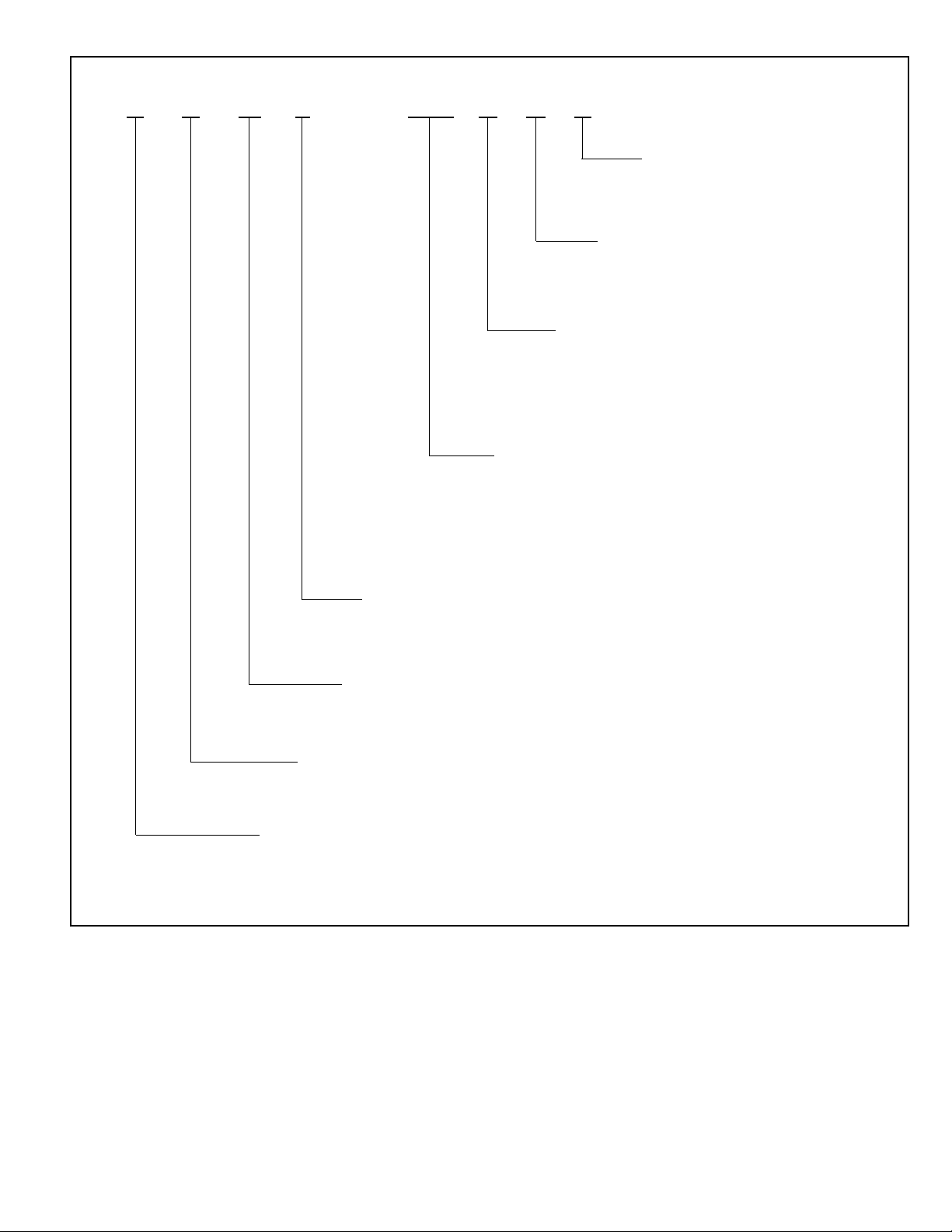
RAWL—125 CAZ
VARIATIONS
ELECTRICAL DESIGNATION
C=208-230V, 3PH, 60HZ
D=460V, 3PH, 60HZ
Y=575V, 3PH, 60HZ
NOMINAL COOLING CAPACITY
120 = 120,000 BTU/HR (SINGLE COMPRESSOR)
125 = 120,000 BTU/HR (TANDEM COMPRESSOR)
150 = 150,000 BTU/HR (TANDEM COMPRESSOR)
180 = 180,000 BTU/HR (TANDEM COMPRESSOR)
240 = 240,000 BTU/HR (TANDEM COMPRESSOR)
COMPRESSOR TYPE
Z = SCROLL
= STANDARD MODEL
A
DESIGN SERIES
(R410A)
COMMERCIAL
REMOTE CONDENSING UNIT
TRADENAME
3
Page 4
WARNING
!
THE MANUFACTURER’S WARRANTY DOES NOT COVER ANY DAMAGE OR DEFECT TO THE AIR CONDITIONER CAUSED BY THE
ATTACHMENT OR USE OF ANY COMPONENTS, ACCESSORIES OR
DEVICES (OTHER THAN THOSE AUTHORIZED BY THE MANUFACTURER) INTO, ONTO OR IN CONJUNCTION WITH THE AIR CONDITIONER, YOU SHOULD BE AWARE THAT THE USE OF UNAUTHORIZED COMPONENTS, ACCESSORIES OR DEVICES MAY
ADVERSELY AFFECT THE OPERATION OF THE AIR CONDITIONER
AND MAY ALSO ENDANGER LIFE AND PROPERTY. THE MANUFACTURER DISCLAIMS ANY RESPONSIBILITY FOR SUCH LOSS OR
INJURY RESULTING FROM THE USE OF SUCH UNAUTHORIZED
COMPONENTS, ACCESSORIES OR DEVICES.
IMPORTANT MESSAGE TO OWNER
The manufacturer assumes no responsibility for equipment installed in violation of any code or regulation. The operation portion of this manual gives
instructions as to the service and care of the unit. It is recommended that
the installer go over the operation portion of this manual with the owner so
that there is a full understanding of the equipment and how it is intended to
function.
These instructions should be read and kept for future reference. It is suggested that this booklet be affixed to or adjacent to the indoor equipment. It
is addressed to your dealer and serviceman, but we highly recommend that
you read it—paying particular attention to the section titled “MAINTENANCE.”
CHECKING PRODUCT RECEIVED
Upon receiving unit, inspect it for any shipping damage. Claims for damage,
either apparent or concealed, should be filed immediately with the shipping
company. Check condensing unit model number, electrical characteristics
and accessories to determine if they are correct. Check system components (evaporator coil, condensing unit, evaporator blower, etc.) to make
sure they are properly matched.
GENERAL
The information contained in this manual has been prepared to assist in the
proper installation, operation and maintenance of the air conditioning system. Improper installation, or installation not made in accordance with these
instructions, can result in unsatisfactory operation and/or dangerous conditions, and can cause the related warranty not to apply.
Read this manual and any instructions packaged with separate equipment
required to make up the system prior to installation. Retain this manual for
future reference.
To achieve unit design operating efficiency and capacity, the indoor cooling
coils listed in the condensing unit specification sheet should be used.
STANDARD UNIT FEATURES
CABINET — Galvanized steel with a durable powder paint finish. Stamped
louvered panels offer 100% protection for the condenser coil.
COMPRESSOR — The Scroll Compressor is hermetically sealed with internal overload protection and durable insulation on motor windings. The
entire compressor is mounted on rubber grommets to reduce vibration and
noise.
CONDENSER COIL — Constructed with copper tubes and aluminum fins
mechanically bonded to the tubes for maximum heat transfer capabilities.
BASE PAN — Galvanized steel with powder coat paint finish.
REFRIGERANT CONNECTIONS — Field piping connections are made
through a fixed panel. This allows complete access or removal of access
panels after piping connections have been made.
4
Page 5

CRANKCASE HEATER — Standard, all models. Prevents refrigerant
igration to compressor(s).
m
LOW AMBIENT CONTROL — A pressure sensitive fan cycling control to
allow unit operation to 0°F is standard.
SERVICE VALVES — Standard on liquid and suction lines. Allows outdoor
section to be isolated from indoor coil.
SERVICE ACCESS — Control box as well as the compressor and other
refrigerant controls being accessible through access panels.
Control box may be open without affecting the normal operation of the unit.
Condenser fan motors are accessible by removing wire grilles.
FILTER DRIER — Standard (uninstalled) on all models. Helps ensure
refrigerant cleanliness.
TRANSFORMER — Step down type, line to 24 volts. Provides control circuit voltage.
CONTACTOR — The contactor is an electrical switch which operates the
compressor and condenser fans.
HIGH PRESSURE CONTROL — Opens the contactor circuit on high refrigerant pressure; manual reset.
LOW PRESSURE CONTROL — Stops compressor operation in the event
of loss of refrigerant.
CONDENSER FAN MOTOR (Direct Drive) — Ball bearing 1075 RPM
motors are mounted to minimize vibration and noise problems. These are
permanent split capacitor types.
TESTING — All units are run tested at the factory prior to shipment. Units
are shipped with a holding charge of nitrogen.
EXTERNAL GAUGE PORTS — Allows pressures to be checked without
removing access panel.
COIL LOUVERS — Helps prevent damage to outdoor coils.
TIME DELAY — Supplied on tandem compressor models to provide a delay
between stages.
EQUIPMENT GROUND — Lug for field connecting of ground wire.
RAWL-120, RAWL-125, RAWL-150, RAWL-180, RAWL-240 FEATURES
FIGURE 1
CONTACTOR TRANSFORMER CAPACITOR
RAWL-120 RAWL-125
HIGH
PRESSURE
SWITCH
HIGH
PRESSURE
SWITCH
LOW
VOLTAGE
CONNECTIONS
LINE
VOLTAGE
ENTRY
24 VOLT
ENTRY
LOW
PRESSURE
GAUGE
PORT
HIGH
PRESSURE
GAUGE
PORT
LIQUID
LINE
LOW
AMBIENT
CONTROL
SCROLL
COMPRESSOR
LOW
VOLTAGE
CONNECTIONS
LOW
PRESSURE
SWITCH
SUCTION
LINE
LINE VOLTAGE
TERMINAL BLOCK
LINE
VOLTAGE
ENTRY
24 VOLT
ENTRY
CONTACTORS TRANSFORMER CAPACITORS
TIME DELAY
RAWL-150
RAWL-180
RAWL-240
LOW
AMBIENT
CONTROL
LOW
PRESSURE
SWITCH
SCROLL
TANDEM
COMPRESSORS
LOW
PRESSURE
GAUGE
PORT
HIGH
PRESSURE
GAUGE
PORT
LIQUID
VALVE
SUCTION
VALVE
5
Page 6
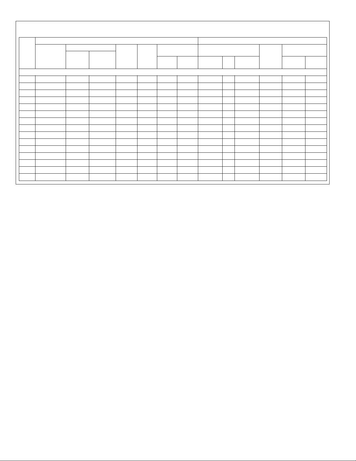
ELECTRICAL AND PHYSICAL DATA
TABLE 1
Model
Number
RAWL-
Phase
Frequency (Hz)
Voltage (Volts)
Compressor
Rated Load
Amperes
(RLA)
ELECTRICAL
Locked Rotor
Amperes
(LRA)
Fan Motor
Full Load
Amperes
(FLA)
Minimum
Circuit
Ampacity
Amperes
Fuse or HACR
Circuit Breaker
Minimum
Amperes
Maximum
Amperes
Face Area
Sq. Ft. (m
Outdoor Coil
No.
2
)
Rows
CFM
[L/s]
PHYSICAL
Refrig.
Per
Circuit
Oz. [g]
Net
Lbs. [kg]
Weight
Shipping
Lbs. [kg]
Rev. 8/14/2008
120CAZ 3-60-208/230 30.1/30.1 225 4.8 43/43 50/50 60/60 27 [2.51] 2 8000 [3775] 339 [9611] 501 [227.3] 541 [245.4]
120DAZ 3-60-460 16.7 114 2.8 24 30 40 27 [2.51] 2 8000 [3775] 339 [9611] 501 [227.3] 541 [245.4]
120YAZ 3-60-575 12.2 80 2 18 25 25 27 [2.51] 2 8000 [3775] 339 [9611] 501 [227.3] 541 [245.4]
125CAZ 3-60-208/230 17.6/17.6 123 4.8 45/45 50/50 60/60 27 [2.51] 2 8000 [3775] 300 [8505] 586 [265.8] 626 [284]
125DAZ 3-60-460 9.6 62 2.8 25 30 30 27 [2.51] 2 8000 [3775] 300 [8505] 586 [265.8] 626 [284]
125YAZ 3-60-575 6.1 40 2 16 20 20 27 [2.51] 2 8000 [3775] 300 [8505] 586 [265.8] 626 [284]
150CAZ 3-60-208/230 22.4/22.4 149 4.8 56/56 70/70 70/70 32.88 [3.05] 2 8000 [3775] 378 [10716] 650 [294.8] 690 [313]
150DAZ 3-60-460 10.6 75 2.8 27 30 35 32.88 [3.05] 2 8000 [3775] 378 [10716] 650 [294.8] 690 [313]
150YAZ 3-60-575 7.7 54 2 20 25 25 32.88 [3.05] 2 8000 [3775] 378 [10716] 650 [294.8] 690 [313]
180CAZ 3-60-208/230 25/25 164 7.2 64/64 70/70 80/80 40.38 [3.75] 2 12000 [5663] 506 [14345] 746 [338.4] 786 [356.5]
180DAZ 3-60-460 12.2 100 4.2 32 35 40 40.38 [3.75] 2 12000 [5663] 506 [14345] 746 [338.4] 786 [356.5]
180YAZ 3-60-575 9 78 3 24 30 30 40.38 [3.75] 2 12000 [5663] 506 [14345] 746 [338.4] 786 [356.5]
240CAZ 3-60-208/230 33.3/33.3 239 7.2 83/83 100/100 110/110 40.38 [3.75] 3 12000 [5663] 655 [18569] 952 [431.8] 992 [450]
240DAZ 3-60-460 17.9 125 3.3 44 50 60 40.38 [3.75] 3 12000 [5663] 655 [18569] 952 [431.8] 992 [450]
240YAZ 3-60-575 12.8 80 2.4 32 35 40 40.38 [3.75] 3 12000 [5663] 655 [18569] 952 [431.8] 992 [450]
6
Page 7

S
T-A08
CONTROL BOX END
DIMENSIONS — 10 TONS
FIGURE 2
HIGH VOLTAGE
13⁄4 DIA. HOLE
OW VOLTAGE
L
7
IA. HOLE
⁄8 D
60.625
8.375
3
7.552
31.333
8.333
2
16.245
11.245
LIQUID LINE
5
⁄8 DIA.
UCTION LINE
S
3
IA.
⁄8 D
1
8.739
.802
7
BOTTOM VIEW
10 TONS
44.750
4
1
.
2
3
9
.9
4
6
ST-A0890-11
7
Page 8
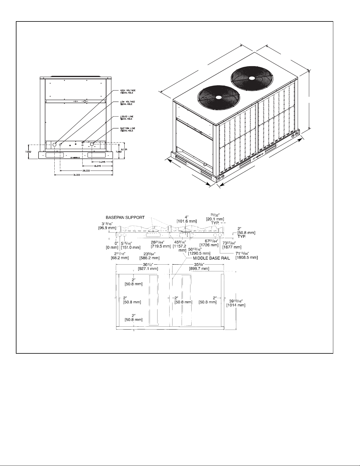
DIMENSIONS — 12.5 TON UNITS
ST-A0890-12
FIGURE 3
2.375
7
39.
94
BOTTOM VIEW
12.5 TONS
38.375
44.750
9
8
.
3
7
8
Page 9
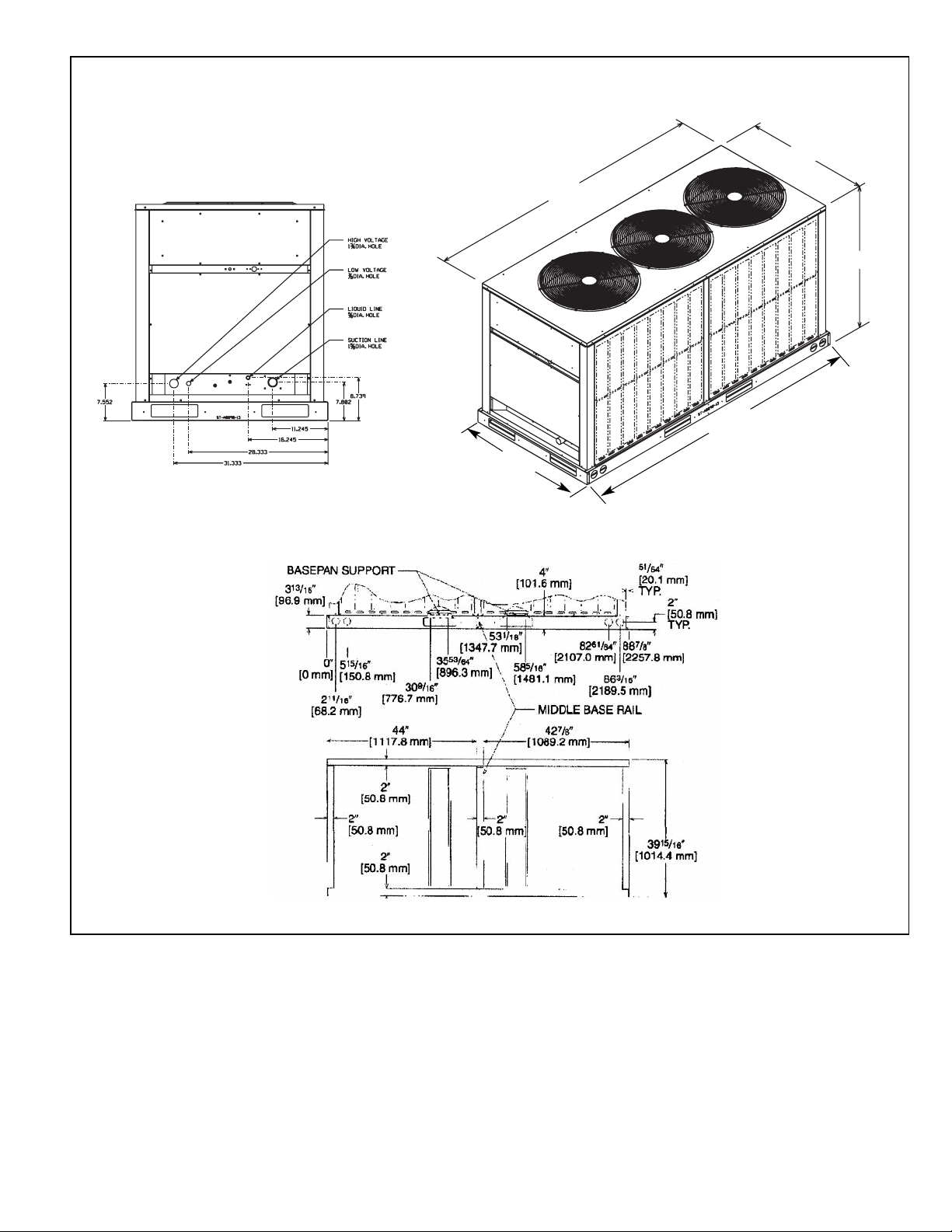
DIMENSIONS — 15 TO 20 TON UNITS
ST-A0890-13
FIGURE 4
7.375
8
3
9
.
9
4
BOTTOM VIEW
RAWL-180 & 240
8.375
3
44.750
8
8
.
8
8
9
Page 10
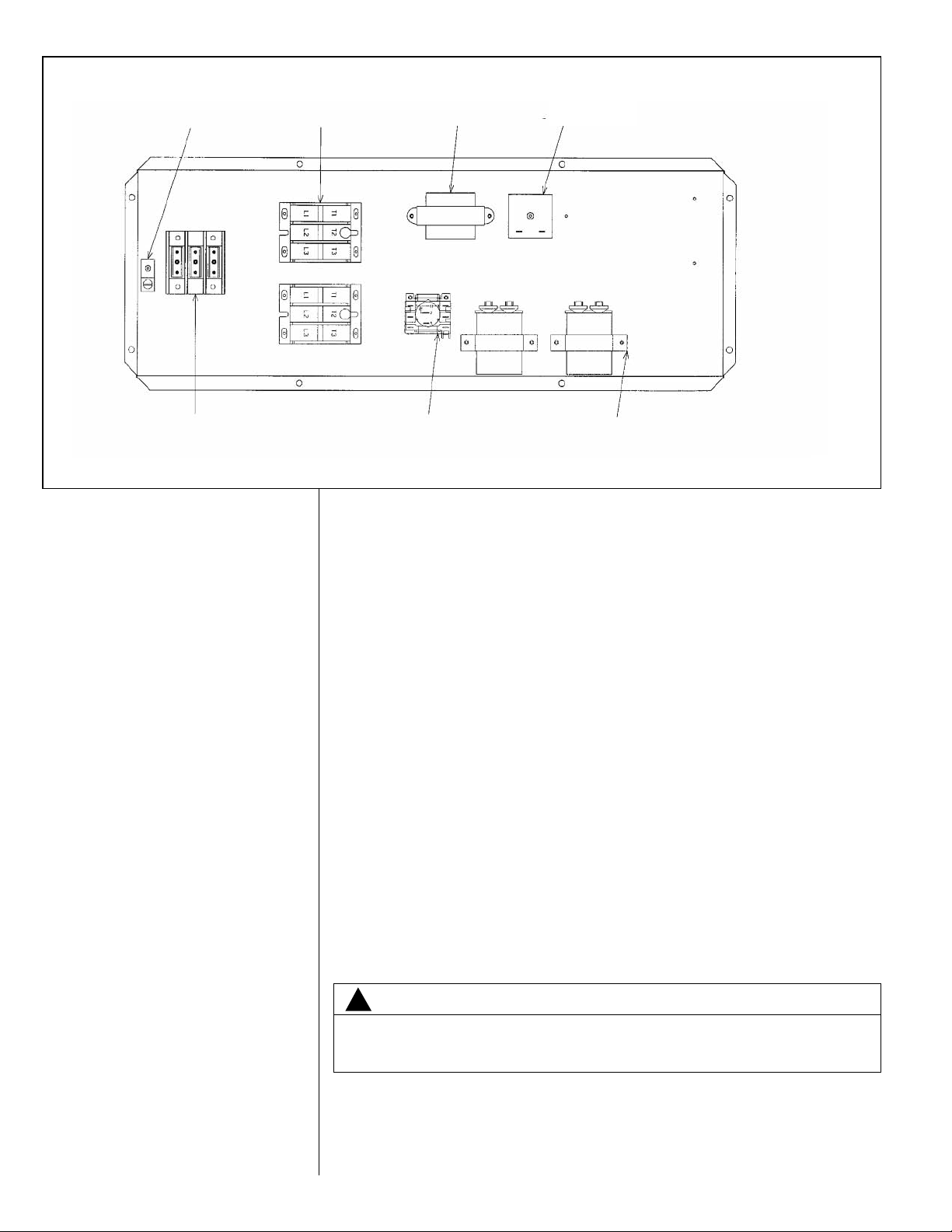
CONTROL BOX CONFIGURATION
FIGURE 5
TRANSFORMERCONTACTORGROUND LUG
TIME DELAY
CONTROL
*
*
*
*
POWER BLOCK RELAY
*NOT REQUIRED ON SINGLE COMPRESSOR 10 TON UNIT. (120)
INSTALLATION
CRANKCASE HEATERS
These units are equipped with a crankcase heater. These crankcase heaters
are factory wired in such a manner that they are in operation whenever the
main power supply to the unit is “on” and compressors are “off.” Before starting
the equipment after prolonged shut-down or at the time of initial spring start-up,
be sure that the circuits to the condensing units are closed for at least 12 hours.
CORROSIVE ENVIRONMENT
The metal parts of this unit may be subject to rust or deterioration if exposed to
a corrosive environment. This oxidation could shorten the equipment’s useful
life. Corrosive elements include salt spray, fog or mist in seacoast areas, sulphur or chlorine from lawn watering systems, and various chemical contaminants from industries such as paper mills and petroleum refineries.
If the unit is to be installed in an area where contaminants are likely to be a
problem, special attention should be given to the equipment location and exposure.
• Avoid having lawn sprinkler heads spray directly on the unit cabinet.
• In coastal areas, locate the unit on the side of the building away from the
waterfront.
• Shielding provided by a fence or shrubs may give some protection, based on
clearances recommended in this book.
Regular maintenance will reduce the build-up of contaminants and help to protect the unit’s finish.
STRAP
A0890-14
10
WARNING
!
DISCONNECT AL L POWER TO UNIT BEFORE STARTING
MA INTENANCE. FAILURE TO DO S O CA N CAUSE ELECTRI CAL
SHOCK RESULTING IN SEVERE PERSONAL INJURY OR DEATH.
• Frequent washing of the cabinet, fan blade and coil with fresh water will
remove most of the salt or other contaminants that build up on the unit.
• Regular cleaning and waxing of the cabinet with a good automobile polish will
provide some protection.
Page 11

• A good liquid cleaner may be used several times a year to remove matter that
will not wash off with water.
Several different types of protective coatings are offered in some areas. These
coatings may provide some benefit, but the effectiveness of such coating materials cannot be verified by the equipment manufacturer.
INSTALLATION GENERAL
The condensing unit should be installed outdoors. It should be located as near
as possible to the evaporator section to keep connecting refrigerant tubing
lengths to a minimum. The unit must be installed to allow a free air flow to the
condenser coils.
If several units are installed adjacent to each other, care must be taken to avoid
recirculation of air from one condenser to another. In all installations, the minimum
clearances shown in Figure 4 must be provided for installation and servicing.
FIGURE 6
CLEARANCES
The unit must not be connected to any duct work. Do not locate unit under a
roof drip; if necessary, install gutters, etc., to prevent water run-off from hitting
the unit. To prevent air recirculation, it is recommended that the unit not be
installed under an overhang, but if necessary allow a minimum of 60 inches
above the unit for air discharge.
ROOFTOP INSTALLATION
If rooftop installation is required, make certain that the building construction is
adequate for the weight of the unit. (Refer to physical data chart.) Before placing the unit on the roof, make certain that the rigging slings are of sufficient
length to maintain equilibrium of the unit when lifting. Under no circumstances
should the unit be lifted by only one corner for rooftop installation.
11
Page 12

15 & 20
TON
10 & 12.5
TON
ST-A0890-17
ST-A0890-18
SLAB INSTALLATION
Condensing units should be set on a solid level foundation. When installed at
round level, the unit should be placed on a 6 inch cement slab. If the pad is
g
formed at the installation site, do not pour the pad tight against the structure,
otherwise vibration will be transmitted from the unit through the pad.
ROOFTOP INSTALLATION – RIGGING
FIGURE 7
CHAIN OR
WEBBING
CORNER WEIGHTS
Model
RAWL-120 501 [227] 123 [56] 132 [60] 119 [54] 127 [58]
RAWL-125 586 [266] 144 [65] 154 [70] 139 [63] 149 [67]
RAWL-150 650 [295] 160 [72] 171 [78] 154 [70] 165 [75]
RAWL-180 746 [338] 183 [83] 196 [89] 177 [80] 189 [86]
RAWL-240 952 [432] 234 [106] 251 [114] 226 [103] 241 [110]
Total
Weight
SPREADER BAR
ABCD
D
D
LIFTING BEAM
CABLE,
LIFTING BEAM
A
CABLE,
CHAIN OR
WEBBING
B
PREADER BAR
S
D
5
⁄8” SHACKLE
(EACH CORNER)
C
12
(EACH CORNER)
5
⁄8” SHACKLE
B
C
A
Page 13

INSTALLATION OF PIPING
WARNING
!
DO NOT USE OXYGEN TO PURGE LINES OR PRESSURE SYSTEM
OR LEAK TEST. OXYGEN REACTS VIOLENTLY WITH OIL, WHICH
F
CAN CAUSE AN EXPLOSION RESULTING IN SEVERE PERSONAL
INJURY OR DEATH.
IMPORTANT: CONDENSING UNITS ARE SHIPPED WITH A NITROGEN
HOLDING CHARGE. EVACUATE CONDENSING UNIT BEFORE CHARGING
WITH REFRIGERANT.
Once located, the condensing unit is ready to be interconnected with the evaporator using ONLY refrigeration grade dehydrated tubing. The following should
be considered when connecting the tubing.
1. If used, it is recommended that the sight glass and liquid line solenoid valve
be installed in the liquid line just prior to the evaporator.
2. Silver solder (such as silfos, Easy Flow, etc.) should be used for all refrigerant
joints. Never use soft solder containing tin and lead to join refrigerant tubing.
3. Thoroughly clean all joints before fluxing. DO NOT USE ACID FLUX.
4. When fluxing, limit the application of paste to the minimum and always apply
flux to the male portion of the connection.
5. Vapor lines should be insulated to prevent condensate drip. Use insulation of
at least 1/2 inch wall thickness. The insulation should be installed on the tubing prior to making the sweat connections.
6. Insulate the liquid line whenever the heat pick-up or transfer can affect the
sub-cooling.
7. Care should be taken to avoid transmission of noise or vibration to building
structure.
REFRIGERANT PIPING DATA
TABLE 2
EQUIVALENT LENGTH (FT.) [m] OF STRAIGHT TYPE “L” TUBING
FOR NON-FERROUS VALVES & FITTINGS (BRAZED)
TUBE SIZE,
O.D.
1
⁄2
5
⁄8
3
⁄4
7
⁄8
11⁄8
13⁄8
15⁄8
21⁄8
SOLENOID
VALVE
70 [21.3]
72 [21.9]
75 [22.9]
78 [23.8]
ANGLE
VALVE
8.3 [2.5]
10.4 [3.2]
12.5 [3.8]
14.6 [4.4]
18.8 [5.7]
22.9 [7.0]
27.1 [8.3]
35.4 [10.8]
SHORT
RADIUS
ELL
1.6 [0.5]
1.9 [0.6]
2.1 [0.7]
2.4 [0.7]
3.0 [0.9]
3.6 [1.1]
4.2 [1.3]
5.3 [1.6]
LONG
RADIUS
ELL
1.0 [0.3]
1.2 [0.4]
1.4 [0.4]
1.6 [0.5]
2.0 [0.6]
2.4 [0.7]
2.8 [0.8]
3.5 [1.1]
TEE LINE
FLOW
1.0 [0.3]
1.2 [0.4]
1.4 [0.4]
1.6 [0.5]
2.0 [0.6]
2.4 [0.7]
2.8 [0.8]
3.5 [1.1]
TEE
BRANCH
FLOW
3.1 [0.9]
3.6 [1.1]
4.2 [1.3]
4.8 [1.5]
6.0 [1.8]
7.2 [2.2]
8.4 [2.6]
10.7 [3.3]
TYPICAL PIPING RECOMMENDATIONS
The following will be of help in accomplishing a successful installation.
1. Size liquid line for no more than 10°F loss which corresponds to approxi-
mately 50 PSIG pressure drop.
2. Size vapor lines for no more than 2°F loss which corresponds to approxi-
mately 5 PSIG pressure drop.
13
Page 14

TYPICAL PIPING RECOMMENDATIONS
LIQUID LINE PRESSURE DROP PER 100 FEET
FIGURE 8
EQUIVALENT LENGTH (TYPE L COPPER TUBING)
LIQUID LINE PRESSURE DROP PER 100 FEET
[30.48 m] EQUIVALENT LENGTH
(TYPE L COPPER TUBING)
NOTES:
1) When evaporator coil is above condenser, the pressure drop due to vertical lift
(.5 PSIG per foot of lift) [1.05 kPa per meter] must be added to the pressure
drop derived from this curve.
2) Size liquid line for no more than 10°F [5.6°C] loss (approximately 50 PSIG total
pressure drop).
3) Do not oversize liquid line. Oversized liquid lines add significantly to the
amount of refrigerant required to charge the system.
4) The maximum recommended velocity with solenoid valves or other quick closing
devices in the liquid line is 300 FPM [1.5 m/s].
SUCTION LINE SYSTEM CAPACITY LOSS IN PERCENT PER 100
FIGURE 9
FEET EQUIVALENT LENGTH (TYPE L COPPER TUBING)
VAPOR LINE SYSTEM CAPACITY LOSS
IN PERCENT PER 100 FEET [30.48 m]
EQUIVALENT LENGTH (TYPE L COPPER TUBING)
OTES:
N
1) The minimum velocity line (700 fpm) [3.6 m/s] is recommended
2) For vapor pressure drop (PSIG), multiply percent (%) loss by 1.18.
) Size vapor lines for no more than 2°F [1.1°C] loss which corresponds to approximately 5 PSIG pres-
3
sure drop.
4) Pitch all horizontal vapor lines downward in the direction of flow (
1
⁄2” [12.7 mm] to 10’ [3.0 m] run).
COIL ABOVE CONDENSING UNIT
FIGURE 10
NOTE: PIPING
ACCESSORIES
SHOWN SHOULD
BE MOUNTED AS
CLOSE TO AIR
HANDLER UNIT
AS POSSIBLE.
COIL BELOW CONDENSING UNIT
FIGURE 11
NOTE: Unit has a scroll compressor which allows pressure to equalize in the system after shut-down. The liquid line solenoid
NOTE: valve may only be used for refrigerant isolation during the off-cycle. The solenoid should be wired in the “Y” circuit as
NOTE: shown in “Typical Field Wiring Connections”.
14
Page 15

3. When making up refrigerant piping, take every precaution to prevent dirt and
moisture from entering the piping.
4. Locate the condensing unit and evaporator(s) as close together as possible
to minimize piping runs.
5. Liquid or vapor lifts not to exceed 60 ft.
6. Line length between condenser and evaporator not to exceed 150’ equivalent length.
TABLE 3
RECOMMENDED VAPOR AND LIQUID LINE
SIZES TO VARIOUS LENGTH OF RUN
EQUIVALENT
LENGTH TO
EVAPORATOR
(FEET)
1 to 15
16 to 50
51 to 100
101 to 150
EQUIVALENT
LENGTH TO
EVAPORATOR
(FEET)
1 to 15
16 to 50
51 to 100
101 to 150
NOTE: Runs between condenser and evaporator not to exceed an equivalent length greater
than 150 feet.
LIQUID LINE O.D.
(INCHES)
COOLING MODEL COOLING MODEL
120
5
⁄8
5
⁄8
5
⁄8
5
⁄8
RECOMMENDED VAPOR AND LIQUID LINE
SIZES TO VARIOUS LENGTH OF RUN
LIQUID LINE O.D.
(INCHES)
COOLING MODEL COOLING MODEL
150 180
5
⁄8
5
⁄8
5
⁄8
5
⁄8
125
5
⁄8
5
⁄8
5
⁄8
5
⁄8
240
5
⁄8
5
⁄8
3
⁄4
3
⁄4
7
⁄8
7
⁄8
7
⁄8
7
⁄8
VAPOR LINE O.D.
(INCHES)
120 125
13⁄8 13⁄8
13⁄8 13⁄8
13⁄8 13⁄8
15⁄8 15⁄8
VAPOR LINE O.D.
(INCHES)
150 180 240
13⁄8 15⁄8 15⁄8
15⁄8 15⁄8 15⁄8
15⁄8 15⁄8 21⁄8
21⁄8 21⁄8 21⁄8
ELECTRICAL WIRING
NNOOTTEE::
Canada) and any local ordinance that may apply.
ELECTRICAL POWER
It is important that proper electrical power is available at the unit. Voltage
must not vary more than 10% of that stamped on the rating plate. (See
Electrical Data Table on Page 17 for minimum and maximum voltage.)
Interphase voltage variation on three-phase units must not be more than
3%. Contact local power company for correction of improper voltage or
phase unbalance.
IMPORTANT: Scroll compressors must be phased correctly for proper compressor rotation. If the compressor is noisy or if suction and discharge pressures do not appear normal, reverse any two power leads to the unit.
Extended run time in reverse rotation will damage the compressor and lead
to premature failure.
POWER WIRING
Power wiring should be run in grounded rain-tight conduit. Wire ampacity
and wire size must comply with the National Electric Code (CEC in Canada)
and all local codes and ordinances.
Field wiring must comply with the National Electric Code (CEC in
15
Page 16

WIRE ROUTING
TABLE 4
FIELD WIRE SIZE FOR 24 VOLT THERMOSTAT
SOLID COPPER WIRE - AWG
3.0 16 14 12 10 10 10
2.5 16 14 12 12 10 10
2.0 18 16 14 12 12 10
50 100 150 200 250 300
Length of Run - Feet (1)
Thermostat
Load - Amps
(1) Wire length equals twice the run distance.
OWER WIRING MUST BE RUN IN CONDUIT. Conduit must be run
P
through the connector panel below the service cover and attached to the
ottom of the control box.
b
If low (extra-low in Canada) voltage control wire is run in conduit with power
upply, Class I insulation is required. If run separate, Class II is required.
s
Low voltage wiring may be run through the insulated bushing provided in
the 7/8” hole in the connector panel then route to the control box.
WARNING
!
AFTER CO M PL E T I O N OF WIRING CH EC K ALL E L E C T R IC A L
CONNECTIONS, INCLUDING FACTORY WIRING WITHIN THE UNIT,
AND MAKE SURE ALL CONNECTIONS ARE TIGHT, REPLACE AND
SECURE ALL ELECTRICAL BOX COVERS AND ACCESS DOORS
BEFORE LEAVING UNIT OR TURNING ON POWER TO CIRCUIT
SUPPLY UNIT. FAILURE TO DO SO CAN CAUSE A FIRE OR ELECTRICAL SHOCK RESULTING IN PROPERTY DAMAGE, PERSONAL
INJURY OR DEATH.
FIELD WIRE SIZE FOR 24 VOLT THERMOSTAT
TABLE 4
GROUNDING
WARNING
!
THIS UNIT MUST BE PERMANENTLY GROUNDED. A GROUND LUG
IS PROVIDED NEAR THE CONTACTOR FOR A GROUND WIRE. FAILURE TO DO SO CAN CAUSE A FIRE OR ELECTRICAL SHOCK
RESULTING IN PROPERTY DAMAGE, SEVERE PERSONAL INJURY
OR DEATH.
A grounding lug is provided in control box for a ground wire.
Grounding may be accomplished by grounding the power line conduit to the
unit.
THERMOSTAT
An appropriate thermostat should be mounted on an inside wall in a location
where it will not be affected by the sun or drafts, from open doors or other
sources. Install, level, and after installation check the thermostat calibration and
recalibrate if necessary. Refer to thermostat manufacturer’s information for
16
additional installation, check-out and operation instructions.
Page 17

EAT
H
ELAYS
R
TYPICAL FIELD WIRING CONNECTIONS
CT
ORANGE YELLOW BROWN RED
FIGURE 10
LIQUID LINE SOLENOID
AIR HANDLER BLOWER
MOTOR RELAY
GROUNDING LUG
CONTROL BOX
CONTROL TRANSFORMERS
IN 208/230V UNITS ARE
ACTORY WIRED 230V.
F
FOR USE ON 208V
APPLICATIONS, THE CT
MUST BE REWIRED. SEE
TRANSFORMER FOR
PROPER WIRING.
CONNECT SUPPLY WIRING TO 60 HERTZ
THREE PHASE FUSED DISCONNECT
(SEE UNIT NAMEPLATE FOR CORRECT
VOLTAGE) USE COPPER CONDUCTORS ONLY
THERMOSTAT AT SUB-BASE
JUMPER MUST BE PRESENT
Y2 USED FOR TWO STAGE
OPERATION. NOT REQUIRED
FOR RAWL-120 SINGLE STAGE
UNIT.
TOOLS REQUIRED FOR INSTALLING &
SERVICING R-410A MODELS
Manifold Sets:
-Up to 800 PSIG High side
-Up to 250 PSIG Low Side
-550 PSIG Low Side Retard
Manifold Hoses:
-Service Pressure Rating of 800 PSIG
Recovery Cylinders:
-400 PSIG Pressure Rating
-Dept. of Transportation 4BA400 or 4BW400
CAUTION
!
R-410A systems operate at higher pressures than R-22 systems. Do not use
R-22 service equipment or components on R-410A equipment.
17
Page 18

SPECIFICATION OF R-410A:
Application: R-410A is not a drop-in replacement for R-22; equipment
designs must accommodate its higher pressures. It cannot be retrofitted into R22 condensing units.
Physical Properties: R-410A has an atmospheric boiling point of -62.9°F and
ts saturation pressure at 77°F is 224.5 psig.
i
omposition: R-410A is an azeotropic mixture of 50% by weight difluo-
C
romethane (HFC-32) and 50% by weight pentafluoroethane (HFC-125).
Pressure: The pressure of R-410A is approximately 60% (1.6 times) greater
than R-22. Recovery and recycle equipment, pumps, hoses and the like need
to have design pressure ratings appropriate for R-410A. Manifold sets need to
range up to 800 psig high-side and 250 psig low-side with a 550 psig low-side
retard. Hoses need to have a service pressure rating of 800 psig. Recovery
cylinders need to have a 400 psig service pressure rating. DOT 4BA400 or
4BW400.
Combustibility: At pressures above 1 atmosphere, mixture of R-410A and air
can become combustible. R-410A and air should never be mixed in tanks or
supply lines, or be allowed to accumulate in storage tanks. Leak checking
should never be done with a mixture of R-410A and air. Leak checking can
be performed safely with nitrogen or a mixture of R-410A and nitrogen.
QUICK REFERENCE GUIDE FOR R-410A
• R-410A refrigerant operates at approximately 60% higher pressure (1.6
times) than R-22. Ensure that servicing equipment is designed to operate
with R-410A.
• R-410A refrigerant cylinders are pink in color.
• R-410A, as with other HFC’s is only compatible with POE oils.
• Vacuum pumps will not remove moisture from oil.
• R-410A systems are to be charged with liquid refrigerants. Prior to March
1999, R-410A refrigerant cylinders had a dip tube. These cylinders should be
kept upright for equipment charging. Post March 1999 cylinders do not have
a dip tube and should be inverted to ensure liquid charging of the equipment.
• Do not install a suction line filter drier in the liquid line.
• A liquid line filter drier is shipped with every unit. Only manufacturer approved
liquid line filter driers can be used. These filter driers are rated for minimum
working pressure of 600 psig.
• Desiccant (drying agent) must be compatible for POE oils and R-410A.
18
REPLACEMENT UNITS
To prevent failure of a new condensing unit, the existing evaporator tubing system must be correctly sized and cleaned or replaced. Care must be exercised
that the expansion device is not plugged. For new and replacement units, a liquid line filter drier should be installed and refrigerant tubing should be properly
sized. Test the oil for acid. If positive, a suction line filter drier is mandatory.
IMPORTANT: WHEN REPLACING AN R-22 UNIT WITH AN R-410A UNIT,
EITHER REPLACE THE LINE SET OR ENSURE THAT THE EXISTING LINE
SET IS THOROUGHLY CLEANED OF ANY OLD OIL OR DEBRIS.
Page 19

EVAPORATOR COIL
REFER TO EVAPORATOR COIL MANUFACTURER’S INSTALLATION
INSTRUCTIONS.
IMPORTANT: The manufacturer is not responsible for the performance and
operation of a mismatched system, or for a match listed with another manufac-
urer’s coil.
t
CAUTION
!
Only use evaporators approved for use on R-410A systems. Use of existing
R-22 evaporators can introduce mineral oil to the R-410A refrigerant forming
two different liquids and decreasing oil return to the compressor. This can
result in compressor failure.
LEAK TESTING
Pressurize line set and coil through service fittings with dry nitrogen to 150
PSIG maximum. Leak test all joints using liquid detergent. If a leak is found,
repair.
WARNING
!
DO NOT USE OXYGEN TO PURGE LINES OR PRESSURE SYSTEM
FOR LEAK TEST. OXYGEN REACTS VIOLENTLY WITH OIL, WHICH
CAN CAUSE AN EXPLOSION RESULTING IN SEVERE PERSONAL
INJURY OR DEATH.
BASIC SYSTEM CHARGE*
TABLE 5
RAWL-120 RAWL-125
339 oz. 300 oz.
[9610 g] [8505 g]
RAWL-150 RAWL-180
378 oz. 506 oz.
[10716 g] [14345 g]
RAWL-240
655 oz.
[18569 g]
*System with 0 Feet of Tubing
EVACUATION AND CHARGING
The evacuation of any system component that has been exposed to atmosphere or lost its charge is essential before charging. Never attempt to operate a system while it is under a vacuum.
NOTE: The condensing unit is shipped with a holding charge of dry nitrogen
which must be purged from the unit before evacuation.
1. Since the condensing unit itself must be evacuated, open the vapor
and liquid service valves.
2. Use a refrigeration type vacuum pump capable of evacuation in the 500
micron range.
3. Connect the vacuum pump to the service manifold assembly with a
pressure gauge that will read 30 inches vacuum. Connect the service
manifold to the vapor line service port. (“Low” shown on label.)
4. With an accurate scale, set refrigerant tank up so its weight can be
measured while in a position to charge liquid. (Unit must be off.)
Energize liquid line solenoid valve by wiring valve to 24V power supply
(or open by manual stem if applicable).
5. Connect to the liquid line service port (“High” shown on label) and evacuate the system below 500 microns.
6. The refrigerant system will now be free of noncondensables.
7. Remove vacuum pump from 3-way valve.
8. Install refrigerant tank (liquid charging) to liquid line service valve.
9. Before tightening, purge tank and service valve hose.
10. Note weight of refrigerant tank. Do not charge more than the sum of the
basic system charge plus the charge per foot of tubing shown in Table 5.
11. De-energize liquid line solenoid valve, if so equipped. Open refrigerant
tank valve. Allow pressure in tank and unit to equalize.
12. Close off service valve to liquid line service port and note weight of
refrigerant tank.
19
Page 20

13. Re-wire liquid line solenoid to thermostat control. Close main disconect switch and turn thermostat to lowest setting.
n
14. Charge unit per Table 5 and the tubing allowance.
15. Adjust refrigerant charge to obtain pressures indicated in the charge
chart.
16. Note weight of refrigerant tank.
17. When system has stabilized, check superheat at the suction line ser-
vice valve. The actual line temperature should be 8° to 20°F higher
than the saturation temperature corresponding to the vapor pressure. If
superheat is measured at evaporator, the actual line temperature
should be 6° to 10° higher than the saturation temperature corresponding to the vapor pressure.
18. Close service ports on vapor and liquid valves. Remove service
gauges.
19. Replace service port caps and valve stem caps. These caps must be
replaced to prevent leaks.
20. Record total charge quantity on rating plate.
REQUIRED OUNCES OF REFRIGERANT CHARGE PER FOOT OF TUBING
Tube Size
O.D., In.
1/2 1.06 0.04
5/8 1.65 0.07
3/4 2.46 0.10
7/8 3.28 0.13
1 1/8 0.22
1 3/8 0.34
1 5/8 0.48
2 1/8 0.84
Quantities based on 110°F liquid and 45°F vapor.
TABLE 6
Liquid
oz/ft
Vapor
oz/ft
FINAL LEAK TESTING
After the unit has been properly evacuated and charged, a halogen leak
detector should be used to detect leaks in the system. All piping within the
condensing unit, evaporator, and interconnecting tubing should be checked
for leaks. If a leak is detected, the refrigerant should be recovered before
repairing the leak. The Clean Air Act prohibits releasing refrigerant into the
atmosphere.
TABLE 7
CHARGING HINTS
SYMPTOM
High head pressure a. Air flow to or from condenser restricted or a. Remove obstruction, relocate,
condensing unit dirty condenser if necessary clean condenser.
b. Faulty condenser fan or motor. b. Replace.
c. Overcharge of refrigerant c. Reduce charge.
d. Air in system. d. Evacuate and recharge.
Low head pressure a. Short of refrigerant. a. Check for leak, add charge.
b. Low evaporator air flow. b. Increase blower speed, check filters.
Low vapor & a. Short of refrigerant. a. Check for leak—add refrigerant.
hot compressor
Excessive sweating a. Low indoor airflow a. Increase speed of air handler blower or reduce
b. Excess refrigerant b. Slowly reduce charge.
20
POSSIBLE CAUSE REMEDY
restriction—replace air filter.
Page 21

PRE-START CHECK
1. Is condensing unit properly located and level?
2. Is air free to travel to and from condensing unit?
3. Is the wiring correct and according to the unit wiring diagram?
4. Are wiring connections tight? (Including those in unit and
compressor electrical box.)
5. Is the unit properly grounded?
6. Is circulating air blower correctly wired?
7. Is condensing unit properly fused?
8. Is the th ermost at le vel, c orrectl y wi red and in a good
location?
9. Is the ductwork correctly sized, run, taped and insulated?
10. Is refrigerant tubing neatly run and vapor line thoroughly
insulated?
11. Is condensate drain line properly sized, run, trapped and
pitched?
12. Are refrigerant connections tight and leak tested?
13. Is filter clean and in place?
14. Does the condenser fan turn free without rubbing?
15. Is the fan tight on the fan shaft?
16. Are all covers and access panels in place to prevent air loss?
YES NO
YES NO
YES NO
YES NO
YES NO
YES NO
YES NO
YES NO
YES NO
YES NO
YES NO
YES NO
YES NO
YES NO
YES NO
YES NO
MAINTENANCE AND OPERATION
1. All access panels must be in place when unit is in operation.
2. For maximum efficiency, the condenser coil must be kept clean.
Periodic inspections, depending on local conditions are recommended.
If it is necessary to clean the condenser coil, use a common garden
hose.
3. Never operate the unit without filters installed in the air handler.
SEQUENCE OF OPERATION – RAWL-120
1. When the room thermostat is set on “Cool”, “Fan Auto”, and the temperature is higher than the thermostat setting, the thermostat “Y1” circuit closes and energizes the compressor contactor (CC) through the
closed contacts of the high pressure and low pressure controls. Power
to the crankcase heater will be de-energized by the auxiliary contacts
(AUX-1).
2. Simultaneously, the “G” circuit provides power to the indoor blower
motor circuit and starts indoor air circulation through the evaporator
coil.
21
Page 22

3. When the discharge pressure increases to 450 psig, the contacts on
he low ambient control (LAC) will allow supply power to start the out-
t
door fan motors (ODF) which begin to pull air through the condenser
coils.
4. The system will continue operation, as long as the room thermostat
“Y1” circuit and all safety device contacts are closed. The low ambient
ontrol (LAC) will open and close, allowing the outdoor fans to maintain
c
discharge pressure between 250 and 450 psig.
5. When the thermostat is satisfied, the “Y1” circuit will open and de-ener-
gize the compressor contactor (CC), stopping compressor operation
and closing the auxiliary contacts (AUX-1) which energizes the
crankcase heater (CCH).
6. The thermostat “G” circuit will stop blower operation.
SEQUENCE OF OPERATION – RAWL-125, -150, -180, -240,
Two Stage
1. When the room thermostat is set on “Cool”, “Fan Auto”, and the tem-
perature is higher than the thermostat setting, the thermostat “Y1” circuit closes and energizes the number one compressor contactor (CC1)
through the closed cooling relay (R) contacts. Power to the crankcase
heater (CCH1) will be de-energized by the auxiliary contacts (AUX-1).
2. Simultaneously, the “G” circuit provides power to the indoor blower
motor circuit and starts indoor air circulation through the evaporator
coil.
3. When the discharge pressure increases to 450 psig, the contacts on
the low ambient control (LAC) will allow supply power to start the outdoor fan motors (ODF) which begin to pull air through the condenser
coils. The system is now in first stage cooling, operating at near fifty
percent of full load capacity.
4. If the temperature at the thermostat continues to increase, the thermo-
stat “Y2” circuit closes and after a full 30 second delay, power passes
through the time delay control (TDC) and energizes the number two
compressor contactor (CC2) through the second set of closed cooling
relay (R) contacts. Power to the crankcase heater (CCH2) will be deenergized by the auxiliary contacts (AUX-2).
5. The system will continue cooling at maximum capacity, as long as the
room thermostat is demanding full load and all safety device contacts
are closed. The low ambient control (LAC) will open and close, allowing
the outdoor fans to maintain discharge pressure between 250 and 450
psig.
6. As the temperature at the thermostat drops enough to satisfy “Y2”, the
circuit will open and de-energize the compressor contactor (CC2), stopping compressor operation and closing the auxiliary contacts (AUX-2),
which energizes the crankcase heater (CCH2).
7. When continued cooling satisfies the “Y1” circuit, it will open and de-
energize the compressor contactor (CC1), stopping compressor operation and closing the auxiliary contacts (AUX-1), which energizes the
crankcase heater (CCH1).
8. The thermostat “G” circuit will stop blower operation.
22
Page 23

CRANKCASE HEATERS
All units are equipped with a crankcase heater. These heaters are factory wired
in such a manner that they are in operation whenever the main power supply to
he unit is “on” and compressors are “off.” Before starting the equipment after
t
prolonged shutdown or at the time of initial start-up, be sure that the circuits to
the condensing units are closed for at least 12 hours.
CONTACTOR (CC)
The contactor is an electrical switch which operates the compressor and
condenser fans. Relay activates contactor when safety circuit is made.
HIGH PRESSURE SWITCH (HPC)
Opens the contactor circuit at 610 psig—Manual Reset—check for cause of
tripping before putting unit back in service.
WARNING
!
DO NOT WIRE AROUND THE HIGH PRESSURE SWITCH. FAILURE
TO FOLLOW THIS WARNING CAN CAUSE AN EXPLOSION RESULTING IN PERSONAL INJURY OR DEATH.
LOW PRESSURE SWITCH (LPC)
Acts as safety against loss of refrigerant. Opens at 50 psig, auto reset.
LOW AMBIENT CONTROL (LAC)
Cycles outdoor fans to maintain adequate discharge pressure. Opens at
250 psig and closes at 450 psig.
ORDER PARTS
When reporting shortages or damaged parts, or when ordering repair parts,
give the complete unit model and serial numbers which are stamped on the
Unit Rating Plate.
23
Page 24

Outdoor Ambient (F° DB)
92-102644-05-01
CAUTION: BEFORE FINAL REFRIGERANT CHECK, INDOOR AIR TEMPERATURE SHOULD BE AT COMFORT CONDITIONS
FOR MOST ACCURATE RESULTS.
INSTRUCTIONS:
1. CONNECT PRESSURE GUAGES TO SUCTION AND LIQUID PORTS ON UNIT.
2. MEASURE AIR TEMPERATURE TO OUTDOOR COIL.
3. PLACE AN "X" ON THE APPROPRIATE CHART WHERE THE SUCTION AND LIQUID PRESSURES CROSS.
4. IF "X" IS BELOW AMBIENT TEMPERATURE LINE, ADD CHARGE AND REPEAT STEP 3.
5. IF "X" IS ABOVE AMBIENT TEMPERATURE LINE, RECOVER EXCESS CHARGE AND REPEAT STEP 3.
6. IF CONDENSER FANS ARE NOT RUNNING, THE HEAD PRESSURE CONTROL MAY REQUIRE JUMPERING.
115
110
105
10095908580
757065
60
55
175
225
275
325
375
425
4
75
525
100 105 110 115 120 125 130 135 140 145 150 155 160 165
Pressure at Liquid Service Port (psig)
1
0 TON CONDENSING UNIT 60HZ.
REFRIGERANT R-410A
Pressure at Suction Service Port (psig)
RE QUIR ED OUN CES R-4 10A
CH ARGE PE R F OOT OF T UBI NG
TUBE SIZE
O.D. IN.
LIQUI D
LINE
VAPOR
LINE
1/2
5/8
1-1 /8
1-3 /8
1.0 6
1.6 5
.22
.34
REFRIGERANT REQUIRED: 300 OZ. WITH 0 FT. OF SUCTION AND LIQUID LINE.
MODEL -AWL-120
10 TON CONDENSING UNIT 60 HZ. REFRIGERANT R-410A
24
Page 25

Outdoor Ambient (F° DB)
92-102644-07-01
CAUTION: BEFORE FINAL REFRIGERANT CHECK, INDOOR AIR TEMPERATURE SHOULD BE AT COMFORT CONDITIONS
FOR MOST ACCURATE RESULTS.
INSTRUCTIONS:
1. CONNECT PRESSURE GUAGES TO SUCTION AND LIQUID PORTS ON UNIT.
2. MEASURE AIR TEMPERATURE TO OUTDOOR COIL.
3. PLACE AN "X" ON THE APPROPRIATE CHART WHERE THE SUCTION AND LIQUID PRESSURES CROSS.
4. IF "X" IS BELOW AMBIENT TEMPERATURE LINE, ADD CHARGE AND REPEAT STEP 3.
5. IF "X" IS ABOVE AMBIENT TEMPERATURE LINE, RECOVER EXCESS CHARGE AND REPEAT STEP 3.
6. IF CONDENSER FANS ARE NOT RUNNING, THE HEAD PRESSURE CONTROL MAY REQUIRE JUMPERING.
Pressure at Liquid Service Port (psig)
10 TON CONDENSING UNIT 60HZ.
REFRIGERANT R-410A
Pressure at Suction Service Port (psig)
RE QUIR ED OUN CES R-4 10A
CH ARGE PE R F OOT OF T UBI NG
TUBE SIZE
O.D. IN.
LIQUI D
LINE
VAPOR
LINE
1/2
5/8
1-1 /8
1-3 /8
1.0 6
1.6 5
.22
.34
115
105
100
90
85
80
75
70
65
60
55
110
95
175
225
275
325
375
425
475
525
100 105 110 115 120 125 130 135 140 145 150 155 160 165
REFRIGERANT REQUIRED: 339 OZ. WITH 0 FT. OF SUCTION AND LIQUID LINE.
MODEL -AWL-125
10 TON CONDENSING UNIT 60 HZ. REFRIGERANT R-410A
25
Page 26

115
110
105
100
95
90
85
80
75
70
65
60
55
200
225
250
275
300
325
350
375
400
425
450
475
500
5
25
100 105 110 115 120 125 130 135 140 145 150 155 160 165
Outdoor Ambient (F° DB)
92-102644-09-00
CAUTION: BEFORE FINAL REFRIGERANT CHECK, INDOOR AIR TEMPERATURE SHOULD BE AT COMFORT CONDITIONS
FOR MOST ACCURATE RESULTS.
INSTRUCTIONS:
1. CONNECT PRESSURE GUAGES TO SUCTION AND LIQUID PORTS ON UNIT.
2. MEASURE AIR TEMPERATURE TO OUTDOOR COIL.
3. PLACE AN "X" ON THE APPROPRIATE CHART WHERE THE SUCTION AND LIQUID PRESSURES CROSS.
4. IF "X" IS BELOW AMBIENT TEMPERATURE LINE, ADD CHARGE AND REPEAT STEP 3.
5. IF "X" IS ABOVE AMBIENT TEMPERATURE LINE, RECOVER EXCESS CHARGE AND REPEAT STEP 3.
6. IF CONDENSER FANS ARE NOT RUNNING, THE HEAD PRESSURE CONTROL MAY REQUIRE JUMPERING.
Pressure at Liquid Service Port (psig)
12.5 TON CONDENSING UNIT 60HZ.
REFRIGERANT R-410A
Pressure at Suction Service Port (psig)
RE QUIR ED OUN CES R-4 10A
CH ARGE PE R F OOT OF T UBI NG
TUBE SIZE
O.D. IN.
LIQUI D
LINE
VAPOR
LINE
1/2
5/8
1-1 /8
1-3 /8
1.0 6
1.6 5
.22
.34
REFRIGERANT REQUIRED: 378 OZ. WITH 0 FT. OF SUCTION AND LIQUID LINE.
MODEL -AWL-150
12.5 TON CONDENSING UNIT 60 HZ. REFRIGERANT R-410A
26
Page 27

Outdoor Ambient (F° DB)
92-102644-11-00
CAUTION: BEFORE FINAL REFRIGERANT CHECK, INDOOR AIR TEMPERATURE SHOULD BE AT COMFORT CONDITIONS
FOR MOST ACCURATE RESULTS.
INSTRUCTIONS:
1. CONNECT PRESSURE GUAGES TO SUCTION AND LIQUID PORTS ON UNIT.
2. MEASURE AIR TEMPERATURE TO OUTDOOR COIL.
3. PLACE AN "X" ON THE APPROPRIATE CHART WHERE THE SUCTION AND LIQUID PRESSURES CROSS.
4. IF "X" IS BELOW AMBIENT TEMPERATURE LINE, ADD CHARGE AND REPEAT STEP 3.
5. IF "X" IS ABOVE AMBIENT TEMPERATURE LINE, RECOVER EXCESS CHARGE AND REPEAT STEP 3.
6. IF CONDENSER FANS ARE NOT RUNNING, THE HEAD PRESSURE CONTROL MAY REQUIRE JUMPERING.
Pressure at Liquid Service Port (psig)
15 TON CONDENSING UNIT 60HZ.
REFRIGERANT R-410A
Pressure at Suction Service Port (psig)
RE QUIR ED OUN CES R-4 10A
CH ARGE PE R F OOT OF T UBI NG
TUBE SIZE
O.D. IN.
LIQUI D
LINE
VAPOR
LINE
1/2
5/8
1-1 /8
1-3 /8
1.0 6
1.6 5
.22
.34
REFRIGERANT REQUIRED: 506 OZ. WITH 0 FT. OF SUCTION AND LIQUID LINE.
115
110
105
1
00
95
90
85
80
75
70
65
60
175
200
225
250
275
300
325
350
375
400
425
450
475
500
5
25
550
100 105 110 115 120 125 130 135 140 145 150 155 160 165
55
MODEL -AWL-180
15 TON CONDENSING UNIT 60 HZ. REFRIGERANT R-410A
27
Page 28

Outdoor Ambient (F° DB)
92-102644-13-00
CAUTION: BEFORE FINAL REFRIGERANT CHECK, INDOOR AIR TEMPERATURE SHOULD BE AT COMFORT CONDITIONS
FOR MOST ACCURATE RESULTS.
INSTRUCTIONS:
1. CONNECT PRESSURE GUAGES TO SUCTION AND LIQUID PORTS ON UNIT.
2. MEASURE AIR TEMPERATURE TO OUTDOOR COIL.
3. PLACE AN "X" ON THE APPROPRIATE CHART WHERE THE SUCTION AND LIQUID PRESSURES CROSS.
4. IF "X" IS BELOW AMBIENT TEMPERATURE LINE, ADD CHARGE AND REPEAT STEP 3.
5. IF "X" IS ABOVE AMBIENT TEMPERATURE LINE, RECOVER EXCESS CHARGE AND REPEAT STEP 3.
6. IF CONDENSER FANS ARE NOT RUNNING, THE HEAD PRESSURE CONTROL MAY REQUIRE JUMPERING.
Pressure at Liquid Service Port (psig)
2
0 TON CONDENSING UNIT 60HZ.
Pressure at Suction Service Port (psig)
RE QUIR ED OUN CES R-4 10A
CH ARGE PE R F OOT OF T UBI NG
TUBE SIZE
O.D. IN.
LIQUI D
LINE
VAPOR
LINE
1/2
5/8
1-1 /8
1-3 /8
1.0 6
1.6 5
.22
.34
REFRIGERANT REQUIRED: 655 OZ. WITH 0 FT. OF SUCTION AND LIQUID LINE.
115
110
1
05
1
00
9
5
90
8
5
8
0
75
70
65
60
55
175
200
225
250
275
300
325
350
375
400
425
450
475
500
525
550
100 105 110 115 120 125 130 135 140 145 150 155 160 165
65**
60**
55**
** DOTTED LINES INDICATE ONLY 1 COMPRESSOR OPERATING.
REFRIGERANT R-410A
MODEL -AWL-240
20 TON CONDENSING UNIT 60 HZ. REFRIGERANT R-410A
28
Page 29

TROUBLESHOOTING CHART
!
WARNING
ISCONNECT ALL POWER TO UNIT BEFORE SERVICING. CONTACTOR MAY BREAK ONLY ONE SIDE. FAILURE TO SHUT OFF
D
POWER CAN CAUSE ELECTRICAL SHOCK RESULTING IN PERSONAL INJURY OR DEATH.
SYMPTOM POSSIBLE CAUSE SOLUTION
Unit will not run • Power off or loose electrical connection • Check for correct voltage at compressor contactor in
• Thermostat out of calibration-set too high • Reset
• Defective contactor • Check for 24 volts at contactor coil - replace if contacts are
• Blown fuses or tripped breaker • Replace fuses or reset breaker
• Transformer defective • Check wiring-replace transformer
• High pressure control open (if provided) • Reset-also see high head pressure remedy
• Interconnecting low voltage wiring damaged. • Replace thermostat wiring
Condenser fan runs, compressor • Loose connection • Check for correct voltage at compressor -
doesn’t check & tighten all connections
• Compressor stuck, grounded or open motor winding, • Wait at least 2 hours for overload to reset.
open internal overload. If still open, replace the compressor.
• Low voltage condition • At compressor terminals, voltage must be within 10% of
Insufficient cooling • Improperly sized unit • Recalculate load
• Improper airflow • Check - should be approximately 400 CFM per ton.
• Incorrect refrigerant charge • Charge per procedure attached to unit service panel
• Air, non-condensibles or moisture in system • Recover refrigerant, evacuate & recharge, add filter drier
• Incorrect voltage • At compressor terminals, voltage must be within 10% of
Compressor short cycles • Incorrect voltage • At compressor terminals, voltage must be – 10% of
• Defective overload protector • Replace - check for correct voltage
• Refrigerant undercharge • Add refrigerant
Registers sweat • Low evaporator airflow • Increase speed of blower or reduce restriction - replace air
High head-low vapor pressures • Restriction in liquid line, expansion device or filter drier • Remove or replace defective component
• TXV does not open • Replace TXV
High head-high or normal vapor • Dirty condenser coil • Clean coil
pressure - Cooling mode • Refrigerant overcharge • Correct system charge
• Condenser fan not running • Repair or replace
• Air or non-condensibles in system • Recover refrigerant, evacuate & recharge
Low head-high vapor pressures • TX valve open • Check bulb mounting - replace valve
• Defective Compressor valves • Replace compressor
Low vapor - cool compressor - • Low evaporator airflow • Increase speed of blower or reduce restriction - replace air
iced evaporator coil filter
• Operating below 65°F outdoors • Check low ambient switch
• Moisture in system • Recover refrigerant - evacuate & recharge - add filter drier
High vapor pressure • Excessive load • Recheck load calculation
• Defective compressor • Replace
Fluctuating head & vapor • TXV hunting • Check TXV bulb clamp - check air distribution on coil -
pressures replace TXV
• Air or non-condensibles in system • Recover refrigerant, evacuate & recharge
Gurgle or pulsing noise at • Air or non-condensibles in system • Recover refrigerant, evacuate & recharge
expansion device or liquid line
control box
open
rating plate volts when unit is operating.
rating plate volts when unit is operating.
nameplate marking when unit is operating
filter
29
Page 30

FIGURE 13
RAWL-120 WIRING SCHEMATIC
SINGLE STAGE
30
Page 31

IGURE 14
F
RAWL-125, -150, -180, -240 WIRING SCHEMATIC
(10, 12.5, 15 & 20 TON)
31
Page 32

32
CM 0608
 Loading...