

Page 1
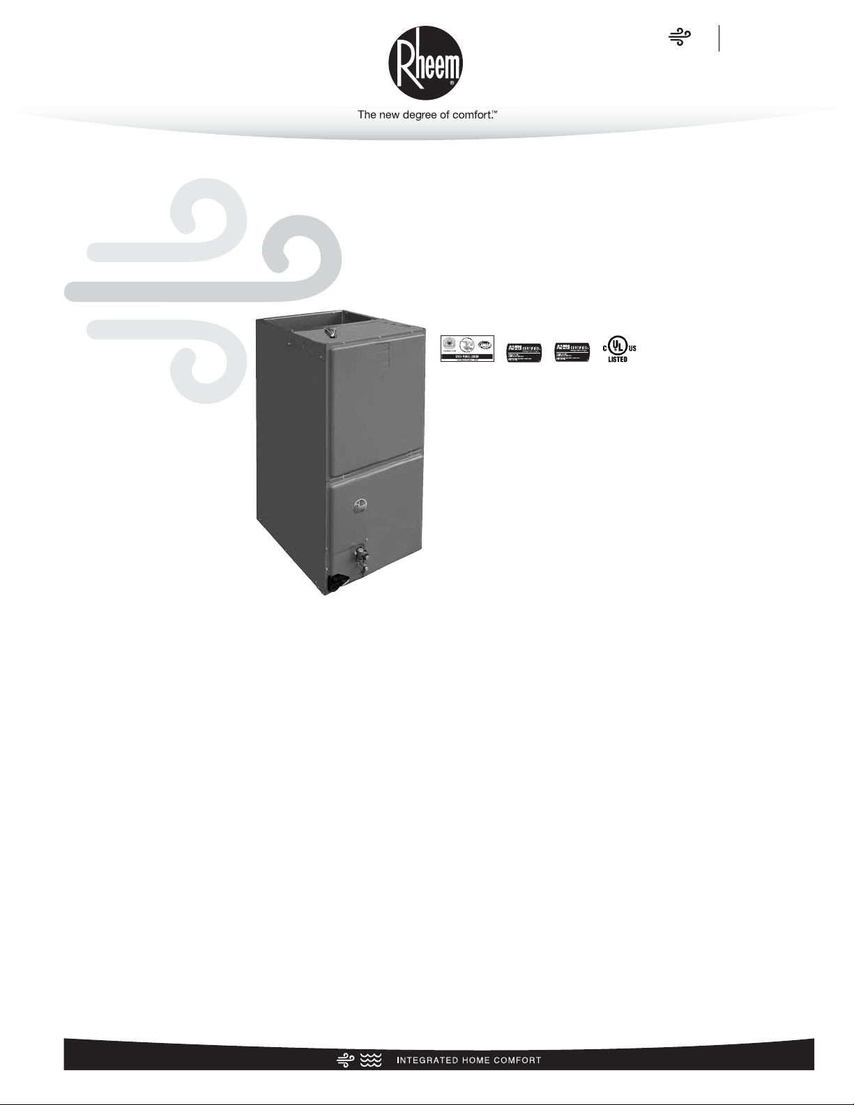
Rheem High Efficiency Air Handler
FORM NO. H11-554
RH1V/RH2V- Series
ECM Motor
Efficiencies up to 16 SEER
• Includes an energy efficient ECM®Motor, which in most applications, enhances the SEER rating of the outdoor unit. It also
slowly ramps its speed up for quiet operation and enhanced
customer satisfaction.
• Versatile 4-way convertible design for upflow, downflow,
horizontal left and horizontal right applications.
• Nominal airflow up to 1.0" external static pressure.
• Factory-installed indoor coil.
• Sturdy cabinet construction with 1.0 inch [25.4 mm] of foil faced
insulation for excellent sound and insulating characteristics.
• Field-installed auxiliary electric heater kits provide exact heat
for indoor comfort. Kits include circuit breakers which meet
U.L. and cUL requirements for service disconnect.
• Dip switch settings for selectable, customized cooling airflow
over a wide variety of applications.
• On-demand dehumidification terminal that adjusts airflow to
help control humidity for unsurpassed comfort in cooling mode.
• External filter required.
• Evaporator coil is constructed of aluminum fins bonded to
internally grooved aluminum tubing.
Air
Air Handlers
RH1V/RH2V Series
Page 2

Air
Table of Contents
RH1V/RH2V Series
2
TABLE OF CONTENTS
Engineering Features ......................................................................................3
Model Number Identification ............................................................................4
Dimensional Data ........................................................................................5-6
Airflow Directional Data ..................................................................................7
Airflow Performance Data (-)H1V ..................................................................8-9
Electrical Data (-)H1V ..............................................................................10-11
Airflow Performance Data (-)H2V ....................................................................12
Electrical Data (-)H2V ..............................................................................13-14
Electrical Wiring ............................................................................................15
Accessories ............................................................................................................15
Limited Warranty ..........................................................................................16
Page 3
Air
Engineering Features
RH1V/RH2V Series
3
Engineering Features
RH1V/RH2V- Series
• Quiet, efficient ECM motor technology providing nominal
airflow up to 1.0 inch [25 kPa] of external static pressure.
• Interface board with dip switches conveniently located in the
blower compartment allows for precise, field selectable airflow to meet the requirements of particular applications.
• Selectable continuous fan “on” options.
• The most compact unit design available.
• Attractive pre-painted cabinet exterior.
• Rugged steel cabinet construction, designed for added
strength and versatility.
• 1.0" foil faced insulation mechanically retained in blower
compartment.
• Four leg rubber insulated motor mount.
• Field-installed auxiliary heater kit includes circuit breakers
that meet UL and cUL requirements as a service disconnect
switch.
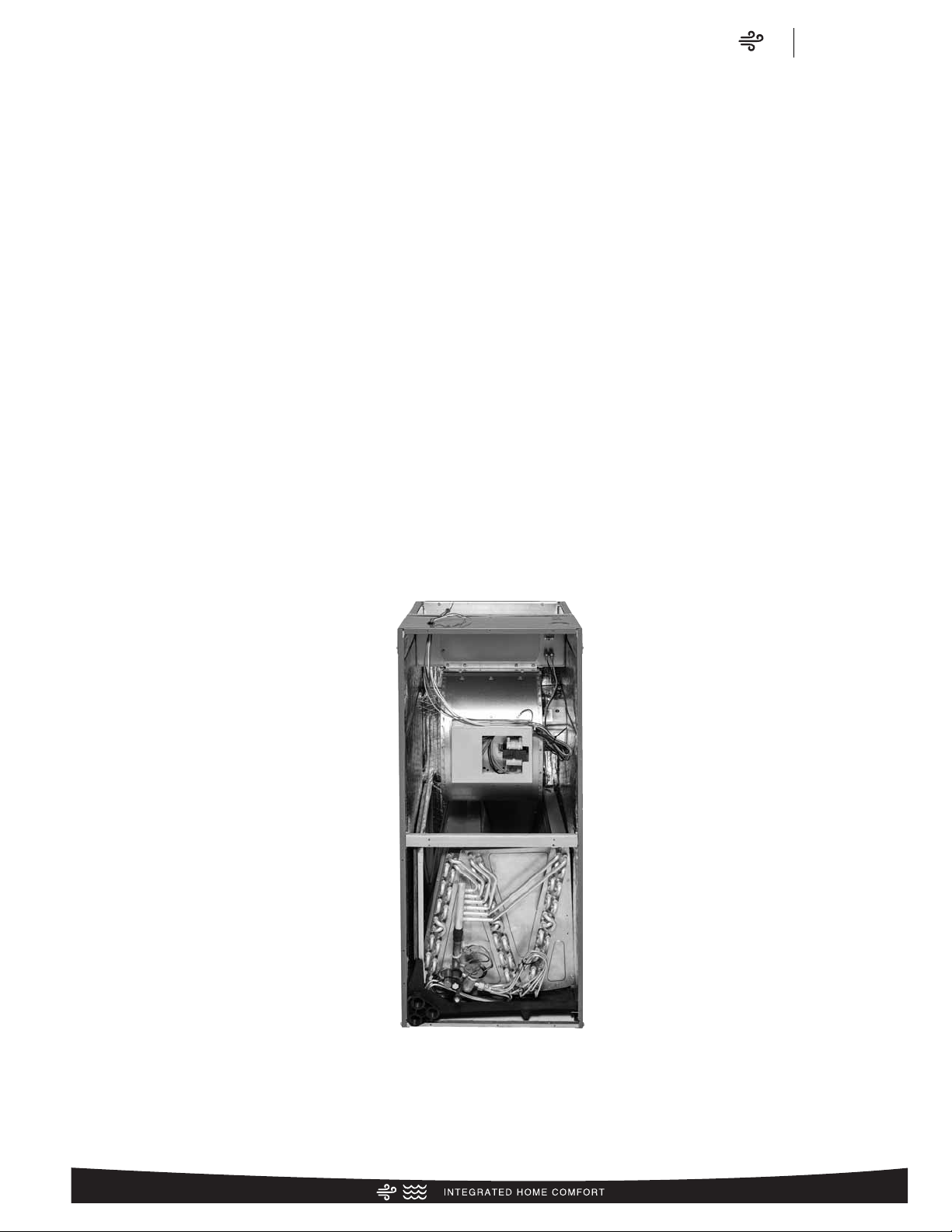
• Blower housing with integrated controls, motor and blower.
Slide out design for service and maintenance convenience.
• Field convertible for vertical upflow, vertical downflow, horizontal left hand or right hand air supply.
• Combustible floor base accessory available when required for
downflow installations on combustible floors.
• Indoor coil design provides low air side pressure drop, high
performance and extremely compact size. All coils come with
PVC condensate elbow standard.
• Coils are constructed of aluminum fins bonded to internally
grooved aluminum tubing.
• Coils are tested at the factory with an extensive refrigerant
leak check.
• Coils have copper sweat refrigerant connections.
• Coils utilize chatleff metering device connections.
• Molded polymer corrosion resistant condensate drain pan is
provided on all indoor coils.
• Supply duct flanges provided as standard on air handler
cabinet.
• Provisions for field electrical connections available from either
side or top of the air handler cabinet.
• Connection point for high voltage wiring is inside the air handler cabinet. Low voltage connection is made on the outside
of the air handler cabinet.
• Concentric knockouts are provided for power connection to
cabinet. Installer may pull desired hole size up to 2 inches
[51 mm] for 1
1
/2 inch [38 mm] conduit.
• Front refrigerant and drain connections.
[ ] Designates Metric Conversions
Page 4

Air
Model Number Identification
RH1V/RH2V Series
4
(-) H 1 V 24 17 S T A N A A ***
Option Code (see ADS-3803)
Blank = None
Minor Series
A = First
Voltage
A = 115/1/60
D = 480/3/60
J = 208/240/1/60
T = 220/240/1/50
Controls
C = Communicating
N = Non-Communicating
Major Series
A = First
Metering Device
T = TEV
E = EEV
P = Piston
Coil Efficiency
S = Standard
M= Medium
H = High
Width
17 = 17.5" [431.8 mm] (600-1200 CFM)
21 = 21" [533.4 mm] (800-1600 CFM)
24 = 24.5" [609.6 mm] (1400-1800 CFM)
Nominal Capacity
24 = 18,000 [5.27 kW]-24,000 [7.03 kW] BTU/H
36 = 30,000 [8.79 kW]-36,000 [10.55 kW] BTU/H
48 = 42,000 [12.31 kW]-48,000 [14.06 kW] BTU/H
60 = 60,000 [17.58 kW]
Motor Type
V = ECM
Stages of Air Flow
1 = Single
2 = Two Stage
Product Category
H = Air Handler
Rheem
[ ] Designates Metric Conversions
Available Models
RH1V2417STANJA
RH1V3617STANJA
RH1V3621MTANJA
RH1V4821STANJA
RH1V4824STANJA
RH1V6024STANJA
RH2V2421HTACJA
RH2V3624HTACJA
RH2V4824HTACJA
RH2V6024HTACJA
Page 5
Air
Dimensional Data
RH1V/RH2V Series
5
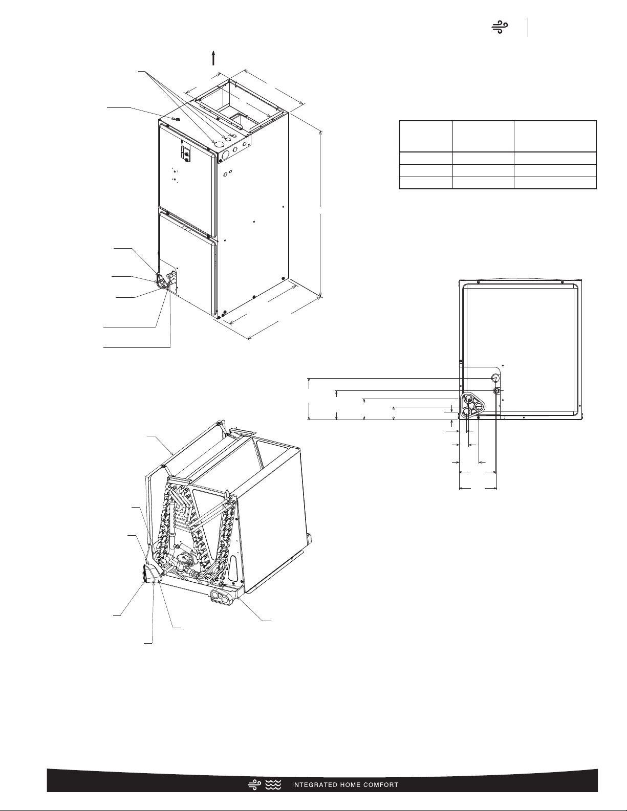
ELECTRICAL CONNECTIONS
Unit Dimensions
[ ] Designates Metric Conversions
( ) Designates Unit with Double Coil Cabinet
UPFLOW UNIT SHOWN:
UNIT MAY BE INSTALLED UPFLOW,
DOWNFLOW, HORIZONTAL RIGHT
OR LEFT AIR SUPPLY.
Return Air Opening Dimensions
[ ] Designates Metric Conversions
( ) Designates Unit with Double Coil Cabinet
HORIZONTAL ADAPTER KIT
VAPOR LINE
CONNECTION
AUXILIARY HORIZONTAL
DRAIN CONNECTION
PRIMARY DRAIN
CONNECTION
AUXILIARY UPFLOW/DOWNFLOW
DRAIN CONNECTION
LIQUID LINE
CONNECTION
VERTICAL DRAIN PAN
MAY EXIT TOP OR EITHER SIDE
HIGH VOLTAGE CONNECTION
3
/32 [27.8 mm], 131/32 [50 mm] DIA. KNOCKOUTS.
1
LOW VOLTAGE CONNECTION
5
/8 [15.9 mm] AND 7/8 [22.2 mm] KNOCKOUT
AUXILIARY DRAIN CONNECTION
3
/4 [19.1 mm] FEMALE PIPE THREAD (NPT)
HORIZONTAL APPLICATION ONLY
PRIMARY DRAIN CONNECTION
3
/4 [19.1 mm] FEMALE PIPE THREAD (NPT)
AUXILIARY DRAIN CONNECTION
3
/4 [19.1 mm] FEMALE PIPE THREAD (NPT)
UPFLOW/DOWNFLOW APPLICATION ONLY
LIQUID LINE CONNECTION
COPPER (SWEAT)
VAPOR LINE CONNECTION
COPPER (SWEAT)
7
/8 [22.2 mm],
SUPPLY AIR
5
/16
10
[262 mm]
A
191/2 [495 mm]
RETURN AIR
OPENING
UPFLOW UNIT SHOWN:
UNIT MAY BE INSTALLED UPFLOW, DOWNFLOW,
HORIZONTAL RIGHT OR LEFT AIR SUPPLY.
NOTE: 24 CLEARANCE REQUIRED IN FRONT OF
UNIT FOR FILTER AND COIL MAINTENANCE.
W
H
11
/16
21
[551 mm]
Model
Cabinet Size
Return Air
Opening Width
(Inches)
17 157/8 193/4
21 193/8 193/4
24 227/8 193/4
Return Air Opening
Depth/Length
(Inches)
515/16
[151 mm]
1
/8
4
[105 mm]
1
3
/16
[76 mm]
3
1
/16 [48 mm]
1
1
/8 [29 mm]
1
/16
1
[27 mm]
1
[35 mm]
2
[71 mm]
3
/8
13
/16
1
/4
5
[133 mm]
3
5
/8
[136 mm]
Page 6
Air
Dimensional Data
RH1V/RH2V Series
6
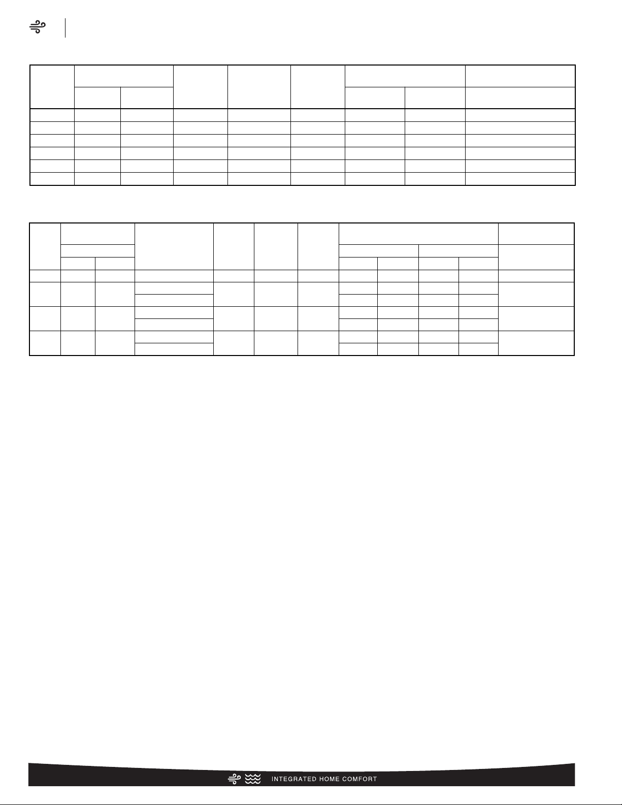
Unit Dimensions & Weights
Model
Size
RH1V
Refrigerant Connections
Sweat (In.) [mm] ID
Unit
Width
“W” In. [mm]
Unit
Height
“H” In. [mm]
Supply
Duct
“A” In. [mm]
Air Flow
CFM (Nom.) [L/s]
Unit Weight/Shipping Weight
(Lbs.) [kg]
Liquid Vapor
Lo Hi
Unit With
Coil (Max. KW)
2417ST
3
/8 [9.53]
3
/4 [19.05] 171/2 [445] 421/2 [1080] 161/2 [406]
600 [283] 800 [378] 82/96 [37/44]
3617ST
3
/8 [9.53]
3
/4 [19.05] 171/2 [445] 421/2 [1080] 161/2 [406]
1000 [472] 1200 [566] 90/104 [41/47]
3621MT
3
/8 [9.53]
7
/8 [22.23] 211/2 [533] 501/2 [1282] 191/2 [495] 1000 [472] 1200 [566] 126/142 [57/64]
4821ST
3
/8 [9.53]
7
/8 [22.23] 211/2 [533] 501/2 [1282] 191/2 [495] 1400 [661] 1600 [755] 130/146 [59/66]
4824ST
3
/8 [9.53]
7
/8 [22.23] 241/2 [622] 501/2 [1282] 231/2 [584] 1600 [755] — 142/160 [64/72]
6024ST
3
/8 [9.53]
7
/8 [22.23] 241/2 [622] 551/2 [1410] 231/2 [584]
— 1800 [850] 162/179 [73/81]
Unit Dimensions & Weights
Model
Size
RH2V
Refrigerant
Connections
Matched
to
Outdoor Unit
Unit
Width
“W” In.
[mm]
Unit
Height
“H” In.
[mm]
Supply
Duct
“A” In.
[mm]
Nominal Coil
Airflow [L/s]
Unit Weight/Shipping
Weight (Lbs.) [kg]
Sweat (in.) [mm] ID
1st Stage 2nd Stage
Unit With
Coil (Max. KW)
Liquid Vapor
ODD* Normal ODD* Normal
2421HT
3
/8 [9.53]3/4 [19.05] (-)ARL/(-)ASL-024JEC 211/2 [533] 421/2 [1080] 191/2 [495] 500 [236] 600 [283] 650 [307] 775 [366] 99/117 [45/51]
3624HT
3
/8 [9.53]7/8 [22.23]
(-)ASL-039JEC
241/2 [622] 551/2 [1410] 231/2 [584]
725 [342] 825 [389] 975 [460] 1175 [555]
129/146 [59/66]
(-)ARL/(-)ASL-0935JEC 825 [389] 950 [448] 1000 [472] 1175 [555]
4824HT3/8 [9.53]7/8 [22.23]
(-)ASL-048JEC
241/2 [622] 551/2 [1410] 231/2 [584]
825 [389] 1000 [472] 1300 [614] 1600 [755]
143/160 [65/72]
(-)ARL-048JEC 1000 [472] 1200 [566] 1350 [637] 1600 [755]
6024HT3/8 [9.53]7/8 [22.23]
(-)ASL-060JEC
241/2 [622] 551/2 [1410] 231/2 [584]
925 [437] 1050 [496] 1325 [625] 1700 [802]
159/176 [72/80]
(-)ARL-060JEC 1025 [484] 1275 [602] 1400 [661] 1700 [802]
*Maximum dehumidification airflow.
[ ] Designates Metric Conversions
Page 7

Air
Airflow Directional Data
RH1V/RH2V Series
7
UPFLOW DOWNFLOW
Airflow Directional Data
HORIZONTAL RIGHT
HAND AIRFLOW
HORIZONTAL LEFT
HAND AIRFLOW
Page 8

Air
Airflow Performance Data
RH1V/RH2V Series
8
Airflow Performance
Airflow performance data is based on cooling performance
with a coil and no filter in place. Select performance table for
appropriate unit size, voltage and number of electric heaters to
be used. Make sure external static applied to unit allows operation within the minimum and maximum limits shown in table
below for both cooling and electric heat operation. For optimum blower performance, operate the unit in the .3 [8 mm] to
.7 inches [18 mm] W.C. external static range. Units with coils
should be applied with a minimum of .1 inch [3 mm] W.C.
external static range.
Airflow Performance and Electrical Data RH1V
External Static Pressure—Inches W.C. [kPa]
ECM
CFM Air Delivery/RPM/Watts—230 Volts
Blower
Size/
Motor
HP [W]
Tonnage
Application
Nominal
Air-Flow
CFM
0.1 [.02] 0.2 [.05] 0.3 [.07] 0.4 [.10] 0.5 [.12] 0.6 [.15] 0.7 [.17]
RPM 522 609 673 757 815 869 938
Model
No.
RH1V
Watts 57 74 89 115 130 144 169
10x8
1/3 [249]
5 Speed
1.5 Ton 600*
CFM [L/s] 597 [282] 608 [287] 607 [286] 616 [291] 616 [291] 618 [292] 613 [289]
Motor
Speed
From
Factory
High
190
995
608 [287]
0.8 [.20]
212
1051
600 [283]
0.9 [.22]
232
1097
594 [280]
1.0 [.24]
209
1047
595 [281]
233
1104
587 [277]
254
1149
577 [272]
RPM 536 608 723 805 864 919 989
Watts 65 85 100 129 145 160 186
10x8
1/3 [249]
5 Speed
1.5 Ton 600*
CFM [L/s] 588 [278] 598 [282] 596 [281]
605 [286]
603 [285] 605 [286] 600 [283]
High
259
1017
810 [382]
289
1070
809 [382]
311
1112
805 [380]
RPM 614 682 763 818 868 917 972
Watts 97 113 144 167 191 209 239
10x8
1/3 [249]
5 Speed
2.0 Ton 800
CFM [L/s] 787 [371] 805 [380] 815 [385]
819 [387]
810 [382] 807 [381] 811 [383]
High
298
1044
798 [377]
332
1098
797 [376]
357
1141
793 [374]
RPM 630 700 783 839 891 941 997
Watts 111 130 165 192 798 240 275
10x8
1/3 [249]
5 Speed
2.0 Ton 800
CFM [L/s] 775 [366] 793 [374] 803 [379]
807 [381]
798 [377] 795 [375] 799 [377]
High
320
1065
1029 [486]
341
1090
1029 [486]
357
1118
1023 [483]
RPM 652 752 812 845 923 945 1007
Watts 134 166 193 212 244 266 280
10x8
1/2 [373]
2.5 Ton 1000*
CFM [L/s]
1001 [472] 1030 [486] 1030 [486] 1035 [488] 1035 [488] 1029 [486] 1029 [486]
High
362
1127
1008 [476]
383
1152
1008 [476]
399
1180
1002 [473]
RPM 714 814 874 907 985 1007 1069
Watts 176 208 235 254 286 308 322
10x8
1/2 [373]
2.5 Ton 1000*
CFM [L/s]
980 [463] 1009 [476] 1009 [476] 1014 [479] 1014 [479] 1008 [476] 1008 [476]
High
426
1108
1238 [584]
472
1156
1233 [582]
496
1194
1228 [580]
RPM 732 831 875 930 981 1005 1077
Watts 215 253 282 314 348 362 409
10x8
1/2 [373]
3.0 Ton 1200*
CFM [L/s]
1220 [576] 1229 [580] 1229 [580] 1229 [580] 1229 [580] 1229 [580] 1238 [584]
High
385
1102
1197 [565]
416
1144
1180 [557]
RPM 646 740 783 851 911 958 1013
3.0 Ton
Watts
1200*
147
CFM [L/s]
1199 [566] 1208 [570] 1208 [570] 1208 [570] 1208 [570] 1208 [570] 1217 [574]
186 207 240 270 296 334
10x10
3/4 [559]
3.0 Ton 1200*
CFM [L/s]
1175 [555] 1200 [566] 1203 [568] 1200 [566] 1200 [566] 1199 [566] 1202 [567]
High
416
1122
1145 [540]
450
1172
1137 [537]
487
1219
1114 [526]
RPM 680 779 826 899 963 1015 1074
Watts 168 213 239 278 313 345 388
10x10
3/4 [559]
3.0 Ton 1200*
CFM [L/s]
1159 [546] 1178 [556] 1176 [555] 1167 [551] 1162 [548] 1155 [545] 1153 [544]
High
287
1026
468
1170
1217 [574]
994 [496]
301
514
1218
1212 [572]
1058
970 [458]
538
1256
1207 [570]
323
1099
967 [456]
RPM 593 650 737 801 867 914 980
Watts 103 124 155 177
RPM 794 893 937 992 1043 1067 1139
207 224 258
10x10
3/4 [559]
Watts 257 295 324 356 390 404 451
10x8
1/2 [373]
2.5 Ton 1000*
CFM [L/s]
1000 [472] 1001 [472] 1011 [477] 1009 [476] 1005 [474] 1000 [472] 996 [470]
High
347
1092
939 [443]
366
1128
910 [429]
394
1174
901 [425]
RPM 627 689 780 849 919 971 1041
Watts 124 151 187 215 250 273 312
10x10
3/4 [559]
2.5 Ton 1000*
CFM [L/s]
984 [464] 979 [462] 984 [464] 976 [461] 967 [456] 956 [451] 947 [447]
High
356
1056
1200 [566]
High
3821MT
with
18 kW
Heat
3621MT
No Heat
3621MT
with
15 kW
Heat
3621MT
No Heat
3617ST
with
18 kW
Heat
3617ST
No Heat
3617ST
with
18 kW
Heat
3617ST
No Heat
2417ST
No
Heater
2417ST
with
13 kW
Heat
2417ST
No Heat
2417ST
with
13 kW
Heat
WARNING: Observe airflow operating limits. Do not operate above 1.0 in. W.C. system external static.
*The airflow for continuous fan is set at 50% of the cooling airflow.
[ ] Designates Metric Conversions
Page 9

Air
Airflow Performance Data
RH1V/RH2V Series
9
Model
No.
RH1V
Voltage Phase Hertz HP [W] RPM Speeds
Circuit
Amps.
Minimum
Circuit
Ampacity
Maximum
Circuit
Protector
2417ST 208/240 1 60 1/3 [249] 300-1100 2 2.8 4.0 15
3617ST 208/240 1 60 1/2 [373] 300-1100 2 4.3 6.0 15
6024ST 206/240 1 60 3/4 [559] 300-1100 2 4.4 6.0 15
3621MT/4821ST/
4824ST/6024ST
208/240 1 60 3/4 [559] 300-1100 2 6.8 9.0 15
Blower Motor Electrical Data RH1V
External Static Pressure—Inches W.C. [kPa]
ECM
CFM Air Delivery/RPM/Watts—230 Volts
Blower
Size/
Motor
HP [W]
Tonnage
Application
Nominal
Air-Flow
CFM
0.1 [.02] 0.2 [.05] 0.3 [.07] 0.4 [.10] 0.5 [.12] 0.6 [.15] 0.7 [.17]
RPM 731 807 859 910 968 1016 1057
Model
No.
RH1V
4821ST
No Heat
Watts 240 273 308 349 383 411 436
10x10
3/4 [559]
3.5 Ton 1400*
CFM [L/s]
1395 [658] 1404 [663] 1413 [667] 1413 [667] 1411 [666] 1411 [666] 1402 [662]
Motor
Speed
From
Factory
High
468
1100
1391 [656]
0.8 [.20]
496
1128
1380 [651]
0.9 [.22]
513
1158
1371 [647]
1.0 [.24]
614
1176
1547 [730]
616
1219
1539 [726]
RPM 826 879 933 984 1025 1067 1119
4821ST
No Heat
Watts 342 375 410 454 486 523 552
10x10
3/4 [559]
4.0 Ton 1600*
CFM [L/s]
1583 [747] 1583 [747] 1583 [747] 1590 [750] 1582 [747] 1566 [739] 1572 [742]
High
653
1222
1484 [700]
688
1255
1467 [692]
697
1304
1452 [685]
RPM 860 919 978 1035 1082 1129 1187
4821ST
with
25 kW
Heat
Watts 363 403 444 495 534 577 613
10x10
3/4 [559]
4.0 Ton 1600*
CFM [L/s]
1567 [740] 1559 [736] 1551 [732] 1550 [732] 1534 [724] 1510 [713] 1508 [712]
High
502
950
1614 [762]
532
981
1606 [758]
568
1018
1583 [747]
RPM 612 698 747 788 835 870 914
4824ST
No Heat
Watts 225 297 334 359 410 439 469
11x11
3/4 [559]
4.0 Ton 1600*
CFM [L/s]
1607 [758] 1615 [762] 1622 [765] 1630 [769] 1637 [773] 1629 [769] 1621 [765]
High
572
1027
1549 [731]
609
1062
1534 [724]
652
1104
1505 [710]
528
1166
1336 [631]
561
1198
1319 [622]
584
1233
1305 [616]
RPM 765 846 902 958 1020 1073 1118
4821ST
with
20 kW
Heat
Watts 261 300 340 387 426 460 490
10x10
3/4 [559]
3.5 Ton 1400*
CFM [L/s]
1379 [651] 1382 [652] 1385 [654] 1380 [651] 1372 [648] 1367 [645] 1352 [638]
High
585
1148
1556 [734]
RPM 658 748 802 847 899 938 987
4824ST
with
25 kW
Heat
Watts 246 325 369 401 459 495 532
11x11
3/4 [559]
4.0 Ton 1600*
CFM [L/s]
1587 [749] 1589 [750] 1589 [750] 1591 [751] 1591 [751] 1577 [744] 1562 [737]
High
624
994
1800 [850]
662
1028
1786 [843]
694
1050
1772 [836]
RPM 676 739 787 840 871 923 950
6024ST
No Heat
Watts
330 376 416 465 504 554 576
11x11
3/4 [559]
5.0 Ton 1800*
CFM [L/s]
1794 [847] 1808 [853] 1808 [853] 1807 [853] 1807 [853] 1807 [853] 1807 [853]
High
676
1047
1762 [832]
717
1083
1748 [825]
752
1107
1734 [818]
RPM 713 778 828 884 917 971 1000
6024ST
with
30 kW
Heat
Watts 361 410 453 505 547 600 625
11x11
3/4 [559]
5.0 Ton 1800*
CFM [L/s]
1756 [829] 1770 [835] 1770 [835] 1769 [835] 1769 [835] 1769 [835] 1769 [835]
High
502
950
1614 [762]
532
981
1606 [758]
568
1018
1583 [747]
RPM 612 698 747 788 835 870 914
6024ST
No Heat
Watts
225 297 334 359 410 439 469
11x11
3/4 [559]
5.0 Ton 1600*
CFM [L/s]
1607 [758] 1615 [762] 1622 [765] 1630 [769] 1637 [773] 1629 [769] 1621 [765]
High
572
1027
1549 [731]
609
1063
1534 [724]
652
1104
1505 [710]
RPM 658 748 802 847 899 938 987
6024ST
with
25 kW
Heat
Watts
246 325 369 401 459 495 532
11x11
3/4 [559]
5.0 Ton 1600*
CFM [L/s]
1587 [749] 1589 [750] 1589 [750] 1591 [751] 1591 [751] 1577 [744] 1562 [737]
High
WARNING: Observe airflow operating limits. Do not operate above 1.0 in. W.C. system external static.
*The airflow for continuous fan is set at 50% of the cooling airflow.
[ ] Designates Metric Conversions
Airflow Performance and Electrical Data (Cont.) RH1V
Page 10

Air
Electrical Data
RH1V/RH2V Series
10
Air Handler
Model
RH1V
Heater Model No.
Heater kW
(208/240V)
PH/HZ
No. Elements
kW Per
Type Supply
Circuit Single
Circuit Multiple
Circuit
Amps.
Motor
Ampacity
Minimum
Circuit
Ampacity
Maximum
Circuit
Protector
2417ST
RXBH-1724?03J 2.25/3.0 1/60 1-3.0 SINGLE
10.8/12.5 2.2 17/19 20/20
RXBH-1724?05J 3.6/4.8 1/60 1-4.8 SINGLE
17.3/20.0 2.2 25/28 25/30
RXBH-1724?07J 5.4/7.2 1/60 2-3.6 SINGLE
26.0/30.0 2.2 36/41 40/45
RXBH-1724?10J 7.2/9.6 1/60 2-4.8 SINGLE
34.6/40.0 2.2 46/53 50/60
RXBH-1724A13J
9.4/12.5 1/60 3/4/17 SINGLE
45.1/52.1 2.2 60/68 60/70
3.1/4.2 1/60 1/4/17 MULTIPLE CKT 1
15.0/17.4 2.2 22/25 25/25
6.3/8.3 1/60 2/4/17 MULTIPLE CKT 2
30.1/34.7 0 38/44 40/45
RXBH-1724A07C 5.4/7.2 3/60 3-2.4 SINGLE
15.0/17.3 2.2 22/25 25/25
RXBH-1724A10C 7.2/9.6 3/60 3-3.2 SINGLE
20.0/23.1 2.2 28/32 30/35
RXBH-1724A13C 9.4/12.5 3/60 3/4/17 SINGLE
26.1/30.1 2.2 36/41 40/45
3617ST
RXBH-1724?03J 2.25/3.0 1/60 1-3.0 SINGLE
10.8/12.5 3.1 18/20 20/20
RXBH-1724?05J 3.6/4.8 1/60 1-4.8 SINGLE
17.3/20.0 3.1 26/29 30/30
RXBH-1724?07J 5.4/7.2 1/60 2-3.6 SINGLE
26.0/30.0 3.1 37/42 40/45
RXBH-1724?10J 7.2/9.6 1/60 2-4.8 SINGLE
34.6/40.0 3.1 48/54 50/60
RXBH-1724A13J
9.4/12.5 1/60 3/4/17 SINGLE
45.1/52.1 3.1 61/69 70/70
3.1/4.2 1/60 1/4/17 MULTIPLE CKT 1
15.0/17.4 3.1 23/26 25/30
6.3/8.3 1/60 2/4/17 MULTIPLE CKT 2
30.1/34.7 0 38/44 40/45
RXBH-1724A15J
10.8/14.4 1/60 3-4.8 SINGLE
51.9/60.0 3.1 69/79 70/80
3.6/4.8 1/60 1-4.8 MULTIPLE CKT 1
17.3/20.0 3.1 26/29 30/30
7.2/9.6 1/60 2-4.8 MULTIPLE CKT 2
34.6/40.0 0 44/50 45/50
RXBH-1724A18J
12.8/17.0 1/60 3/5/68 SINGLE
61.6/70.8 3.1 81/93 90/100
4.3/5.7 1/60 1/5/68 MULTIPLE CKT 1
20.5/23.6 3.1 30/34 30/35
8.5/11.3 1/60 2/5/68 MULTIPLE CKT 2
41.1/47.2 0 52/59 60/60
RXBH-1724A07C 5.4/7.2 3/60 3-2.4 SINGLE
15.0/17.3 3.1 23/26 25/30
RXBH-1724A10C 7.2/9.6 3/60 3-3.2 SINGLE
20.0/23.1 3.1 29/33 30/35
RXBH-1724A13C 9.4/12.5 3/60 3/4/17 SINGLE
26.1/30.1 3.1 37/42 40/45
RXBH-1724A15C 10.8/14.4 3/60 3-4.8 SINGLE
30.0/34.6 3.1 42/48 45/50
RXBH-1724A18C 12.8/17.0 3/60 3/5/68 SINGLE
35.5/41.0 3.1 49/56 50/60
3821MT
4821ST
RXBH-1724?05J 3.6/4.8 1/60 1-4.8 SINGLE
17.3/20.0 4.0 27/30 30/30
RXBH-1724?07J 5.4/7.2 1/60 2-3.6 SINGLE
26.0/30.0 4.0 38/43 40/45
RXBH-1724?10J 7.2/9.6 1/60 2-4.8 SINGLE
34.6/40.0 4.0 49/55 50/60
RXBH-1724A15J
10.8/14.4 1/60 3-4.8 SINGLE
51.9/60.0 4.0 70/80 70/80
3.6/4.8 1/60 1-4.8 MULTIPLE CKT 1
17.3/20.0 4.0 27/30 30/30
7.2/9.6 1/60 2-4.8 MULTIPLE CKT 2
34.6/40.0 0.0 44/50 45/50
RXBH-1724A18J
12.8/17.0 1/60 4/4/26 SINGLE
61.6/70.8 4.0 82/94 90/100
6.4/8.5 1/60 2/4/26 MULTIPLE CKT 1
30.8/35.4 4.0 44/50 45/50
6.4/8.5 1/60 2/4/26 MULTIPLE CKT 2
30.8/35.4 0.0 39/45 40/45
RXBH-24A20J
(3
1
/2
, 4-ton only)
14.4/19.2 1/60 4-48 SINGLE
69.2/80 4.0 92/105 100/110
7.2/9.6 1/60 2-4.8 MULTIPLE CKT 1
34.6/40.0 4.0 49/55 50/60
7.2/9.6 1/60 2-4.8 MULTIPLE CKT 2
34.6/40.0 0.0 44/50 45/50
RXBH-24A25J
(4-ton only)
18.0/24.0 1/60 6-4.0 SINGLE
86.4/99.9 4.0 113/130 125/150
6.0/8.0 1/60 2-4.0 MULTIPLE CKT 1
28.8/33.3 4.0 42/47 45/50
6.0/8.0 1/60 2-4.0 MULTIPLE CKT 2
28.8/33.3 0.0 36/42 40/45
6.0/8.0 1/60 2-4.0 MULTIPLE CKT 3
28.8/33.3 0.0 36/42 40/45
Electrical Data – With Electric Heat RH1V
Installation of the U.L. Listed original equipment manufacturer provided heater kits listed in the following table is recommended for all
auxiliary heating requirements.
• Supply circuit protective devices may be fuses or “HACR” type circuit breakers.
• Largest motor load is included in single circuit and multiple circuit 1.
• If non-standard fuse size is specified, use next size larger standard fuse size.
• J Voltage (230V) single phase air handler is designed to be used with single or three phase 230 volt electric heaters. In the case of connecting 3-phase power to the air handler terminal block
without the heater, bring only two leads to the terminal block cap, insulate and fully secure the third lead.
[ ] Designates Metric Conversions
Page 11

Air
Electrical Data
RH1V/RH2V Series
11
Electrical Data – With Electric Heat RH1V (Cont.)
Installation of the U.L. Listed original equipment manufacturer provided heater kits listed in the following table is recommended for all
auxiliary heating requirements.
Air Handler
Model
RH1V
Heater Model No.
Heater kW
(208/240V)
PH/HZ
No. Elements
kW Per
Type Supply
Circuit Single
Circuit Multiple
Circuit
Amps.
Motor
Ampacity
Minimum
Circuit
Ampacity
Maximum
Circuit
Protector
3821MT
4821ST
RXBH-1724A07C 5.4/7.2 3/60 3-2.4 SINGLE
15.0/17.3 4.0 24/27 25/30
RXBH-1724A10C 7.2/9.6 3/60 3-3.2 SINGLE
20.0/23.1 4.0 30/34 30/35
RXBH-1724A15C 10.8/14.4 3/60 3-4.8 SINGLE
30.0/34.6 4.0 43/49 45/50
RXBH-1724A18C 12.8/17.0 3/60 3/2/84 SINGLE
35.6/41.0 4.0 50/57 50/60
RXBH-24A20C*
(3
1
/2
, 4-ton only)
14.4/19.2 3/60 3-3.2 SINGLE
40.0/46.2 4.0 55/63 60/70
7.2/9.6 3/60 3-3.2 MULTIPLE CKT 1
20.0/23.1 4.0 30/34 30/35
7.2/9.6 3/60 3-3.2 MULTIPLE CKT 2
20.0/23.1 0.0 25/29 25/30
RXBH-24A25C*
(4-ton only)
18.0/24.0 3/60 6-4.0 SINGLE
50.0/57.8 4.0 68/78 70/80
9.0/12.0 3/60 3-4.0 MULTIPLE CKT 1
25.0/28.9 4.0 37/42 40/45
9.0/12.0 3/60 3-4.0 MULTIPLE CKT 2
25.0/28.9 0.0 32/37 35/40
4824ST
6024ST
RXBH-1724?05J 3.6/4.8 1/60 1-4.8 SINGLE
17.3/20.0 4.4 28/31 30/35
RXBH-1724?07J 5.4/7.2 1/60 2-3.6 SINGLE
26.0/30.0 4.4 38/43 40/45
RXBH-1724?10J 7.2/9.6 1/60 2-4.8 SINGLE
34.6/40.0 4.4 49/56 50/60
RXBH-1724A15J
10.8/14.4 1/60 3-4.8 SINGLE
51.9/60.0 4.4 71/81 80/90
3.6/4.8 1/60 1-4.8 MULTIPLE CKT1
17.3/20.0 4.4 28/31 30/35
7.2/9.6 1/60 2-4.8 MULTIPLE CKT 2
34.6/40.0 0 44/50 45/50
RXBH-1724A18J
12/8/17 1/60 4/4/26 SINGLE
61.6/70.8 4.4 83/94 90/100
6.4/8.5 1/60 2/4/26 MULTIPLE CKT 1
30.8/35.4 4.4 44/50 45/50
6.4/8.5 1/60 2/4/26 MULTIPLE CKT 2
30.8/35.4 0 39/45 40/45
RXBH-24A20J
14.4/19.2 1/60 4-4.8 SINGLE
69.2/80 4.4 93/106 100/110
7.2/9.6 1/60 2-4.8 MULTIPLE CKT 1
34.6/40.0 4.4 49/56 50/60
7.2/9.6 1/60 2-4.8 MULTIPLE CKT 2
34.6/40.0 0 44/50 45/50
RXBH-24A25J
18.0/24.0 1/60 6-4.0 SINGLE
86.4/99.9 4.4 114/131 125/150
6.0/8.0 1/60 2-4.0 MULTIPLE CKT 1
28.8/33.3 4.4 42/48 45/50
6.0/8.0 1/60 2-4.0 MULTIPLE CKT 2
28.8/33.3 0 36/42 40/45
6.0/8.0 1/60 2-4.0 MULTIPLE CKT 3
28.8/33.3 0 36/42 40/45
RXBH-24A30J
(1800 CFM only)
21.6/28.8 1/60 6-4.8 SINGLE
103.8/120. 4.4 136/156 150/175
RXBH-24A30J
(5-ton only)
(1800 CFM only)
7.2/9.6 1/60 2-4.8 MULTIPLE CKT 1
34.6/40.0 4.4 49/56 50/60
7.2/9.6 1/60 2-4.8 MULTIPLE CKT 2
34.6/40.0 0 44/50 45/50
7.2/9.6 1/60 2-4.8 MULTIPLE CKT 3
34.6/40.0 0 44/50 45/50
RXBH-1724A07C 5.4/7.2 3/60 3-2.4 SINGLE
15.0/17.3 4.4 25/28 25/30
RXBH-1724A10C 7.2/9.6 3/60 3-3.2 SINGLE
20.0/23.1 4.4 31/35 35/35
RXBH-1724A15C 10.8/14.4 3/60 3-4.8 SINGLE
30.0/34.6 4.4 43/49 45/50
RXBH-1724A18C 12.8/17.0 3/60 3/2/84 SINGLE
35.6/41.0 4.4 50/57 50/60
RXBH-24A20C*
14.4/19.2 3/60 3-3.2 SINGLE
40.0/46.2 4.4 56/64 60/70
7.2/9.6 3/60 3-3.2 MULTIPLE CKT 1
20.0/23.1 4.4 31/35 35/35
7.2/9.6 3/60 3-3.2 MULTIPLE CKT 2
20.0/23.1 0 25/29 25/30
RXBH-24A25C*
18.0/24.0 3/60 6-4.0 SINGLE
50.0/57.8 4.4 68/78 70/80
9.0/12.0 3/60 3-4.0 MULTIPLE CKT 1
25.0/28.9 4.4 37/42 40/45
9.0/12.0 3/60 3-4.0 MULTIPLE CKT 2
25.0/28.9 0 32/37 35/40
RXBH-24A30C*
(1800 CFM only)
21.6/28.8 3/60 6-4.8 SINGLE
60.0/69.4 4.4 81/93 90/100
RXBH-24A30C
(5-ton only) (1800 CFM only)
10.8/14.4 3/60 3-4.8 MULTIPLE CKT 1
30.0/34.7 4.4 43/50 45/50
10.8/14.4 3/60 3-4.8 MULTIPLE CKT 2
30.0/34.7 0 38/44 40/45
• Supply circuit protective devices may be fuses or “HACR” type circuit breakers.
• Largest motor load is included in single circuit and multiple circuit 1.
• If non-standard fuse size is specified, use next size larger standard fuse size.
• J Voltage (230V) single phase air handler is designed to be used with single or three phase 230 volt electric heaters. In the case of connecting 3-phase power to the air handler terminal block
without the heater, bring only two leads to the terminal block cap, insulate and fully secure the third lead.
[ ] Designates Metric Conversions
Page 12

Air
Airflow Performance Data
RH1V/RH2V Series
12
Airflow Performance
Airflow performance data is based on cooling performance
with a coil and no filter in place. Select performance table for
appropriate unit size, voltage and number of electric heaters to
be used. Make sure external static applied to unit allows operation within the minimum and maximum limits shown in table
below for both cooling and electric heat operation. For optimum blower performance, operate the unit in the .3 [8 mm] to
.7 inches [18 mm] W.C. external static range. Units with coils
should be applied with a minimum of .1 inch [3 mm] W.C.
external static range.
Airflow Performance Data RH2V
Outdoor
Unit
Blower
Nominal
Airflow
CFM
0.20 0.40 0.60 0.80
RARL-024
or
RASL-024
10 x 8
1/3
600
CFM 575 [271] 600 [283] 625 [295] 600 [283]
RPM 540 695 825 940
0.90
575 [271]
985
0.70
625 [295]
885
0.50
625 [295]
760
0.30
600 [283]
620
External Static Pressure - In. W.C.
CFM [L/s] Air Delivery/RPM/Watts-230 Volts
External Static Pressure – Inches W.C. [kPa]
0.10
550 [260]
455
1.00
550 [260]
1030
170
825 [389]
1020
250
135
825 [389]
925
205
105
800 [378]
810
160
70
775 [366]
685
115
40
775 [366]
540
70
185
825 [389]
1065
270
Watts 55 85 120 150
775
CFM 775 [366] 800 [378] 825 [389] 825 [389]
RPM 615 750 870 975
Watts
90 135 180 225
Air
Handler
RH2V
2421HT
First
Stage
Second
Stage
Size
Motor HP
Unit
Operation
3624HT
RARL-036
or
RASL-036
11 x 11
3/4
First
Stage
950
CFM
950 [448] 950 [448] 1000 [472] 975 [460] 975 [460] 975 [460] 925 [437] 925 [437] 925 [437] 925 [437]
RPM 495 555 610 665 720 770 820 865 910 955
Watts 95 115 140 165 185 210 240 265 290 320
Second
Stage
1175
CFM 1150 [543] 1150 [543] 1175 [555] 1175 [555] 1175 [555] 1150 [543] 1150 [543] 1150 [543] 1125 [531] 1125 [531]
RPM 550 600 650 700 750 800 850 900 925 975
Watts 125 175 200 225 250 275 300 325 375 400
RASL-039
First
Stage
825
CFM 825 [389] 825 [389] 875 [413] 875 [413] 850 [401] 850 [401] 825 [389] 825 [389] 800 [378] 800 [378]
RPM 455 515 575 630 680 730 780 830 875 915
Watts 70 90 115 135 155 180 205 230 255 280
Second
Stage
1175
CFM 1150 [543] 1150 [543] 1175 [555] 1175 [555] 1175 [555] 1150 [543] 1150 [543] 1150 [543] 1125 [531] 1125 [531]
RPM 550 600 650 700 750 800 850 900 925 975
Watts
125 175 200 225 250 275 300 325 375 400
4824HT
RARL-048
11 x 11
3/4
First
Stage
1200
CFM
1275 [602] 1275 [602] 1250 [590] 1250 [590] 1275 [602] 1250 [590] 1250 [590] 1225 [578] 1225 [578] 1225 [578]
RPM 533 593 649 702 752 798 841 881 917 950
Watts 131 161 191 221 250 279 307 335 363 390
Second
Stage
1600
CFM 1650 [779] 1650 [779] 1675 [791] 1700 [802] 1700 [802] 1700 [802] 1675 [791] 1675 [791] 1675 [791] 1675 [791]
RPM 635 698 761 824 887 950 1013 1075 1120 1006
Watts 244 293 340 384 425 464 500 533 564 592
RASL-048
First
Stage
1000
CFM 1000 [472] 1000 [472] 1025 [484] 1025 [484] 1000 [472] 1000 [472] 975 [460] 975 [460] 975 [460] 975 [460]
RPM 500 575 625 675 725 775 825 875 925 950
Watts 100 125 150 175 200 225 250 275 300 325
Second
Stage
1600
CFM 1650 [779] 1650 [779] 1675 [791] 1700 [802] 1700 [802] 1700 [802] 1675 [791] 1675 [791] 1675 [791] 1675 [791]
RPM 635 698 761 824 887 950 1013 1075 1120 1006
Watts
244 293 340 384 425 464 500 533 564 592
6024HT
RARL-060
11 x 11
3/4
First
Stage
1275
CFM
1275 [602] 1275 [602] 1275 [602] 1275 [602] 1275 [602] 1275 [602] 1275 [602] 1250 [590] 1250 [590] 1250 [590]
RPM 577 633 687 738 786 831 874 914 951 986
Watts 159 189 218 248 279 310 341 372 404 436
Second
Stage
1700
CFM 1625 [767] 1625 [767] 1650 [779] 1675 [791] 1675 [791] 1650 [779] 1650 [779] 1625 [767] 1625 [767] 1625 [767]
RPM 691 742 790 835 877 916 953 986 1016 1044
Watts 289 334 377 417 456 493 529 562 593 623
RASL-060
First
Stage
1050
CFM 1050 [496] 1050 [496] 1075 [507] 1075 [507] 1050 [496] 1025 [484] 1025 [484] 1025 [484] 1025 [484] 1000 [472]
RPM 525 575 625 675 750 800 825 875 925 975
Watts 100 125 150 175 225 250 275 300 325 350
Second
Stage
1700
CFM 1625 [767] 1625 [767] 1650 [779] 1675 [791] 1675 [791] 1650 [779] 1650 [779] 1625 [767] 1625 [767] 1625 [767]
RPM 691 742 790 835 877 916 953 986 1016 1044
Watts 289 334 377 417 456 493 529 562 593 623
Cabinet
Size
24
21
24
24
IMPORTANT: Observe airflow operating limits. Do not operate above 1.0 in. W.C. system external static.
[ ] Designates Metric Conversions
Page 13

Air
Electrical Data
RH1V/RH2V Series
13
Air Handler
Model
RH2V
Heater Model No.
Heater kW
(208/240V)
PH/HZ
No. Elements
kW Per
Type Supply
Circuit Single
Circuit Multiple
Circuit
Amps.
Motor
Ampacity
Minimum
Circuit
Ampacity
Maximum
Circuit
Protection
2421HT
RXBH-1724?05J 3.6/4.8 1/60 1 - 4.8 SINGLE
17.3/20.0 1.7 24/28 25/30
RXBH-1724?07J 5.4/7.2 1/60 2 - 3.6 SINGLE
26.0/30.0 1.7 35/40 35/40
RXBH-1724?10J 7.2/9.6 1/60 2 - 4.8 SINGLE
34.6/40.0 1.7 46/53 50/60
3624HT
RXBH-1724?05J 3.6/4.8 1/60 1 - 4.8 SINGLE
17.3/20.0 4.9 28/32 30/35
RXBH-1724?07J 5.4/7.2 1/60 2 - 3.6 SINGLE
26.0/30.0 4.9 39/44 40/45
RXBH-1724?10J 7.2/9.6 1/60 2 - 4.8 SINGLE
34.6/40.0 4.9 50/57 50/60
RXBH-1724A13J 9.4/12.5 1/60 3-4.17 SINGLE
45.1/52.1 4.9 63/72 70/80
RXBH-1724A13J
3.1/4.2 1/60 1-4.17 MULTIPLE CKT 1
15.0/17.4 4.9 25/28 25/30
6.3/8.3 1/60 2-4.17 MULTIPLE CKT 2
30.1/34.7 0.0 38/44 40/45
RXBH-1724A15J 10.8/14.4 1/60 3-4.8 SINGLE
51.9/60.0 4.9 71/82 80/90
RXBH-1724A15J
3.6/4.8 1/60 1 - 4.8 MULTIPLE CKT 1
17.3/20.0 4.9 28/32 30/35
7.2/9.6 1/60 2 - 4.8 MULTIPLE CKT 2
34.6/40.0 0.0 44/50 45/50
RXBH-1724A18J 12.8/17 1/60 3-5.68 SINGLE
61.6/70.8 4.9 84/95 90/100
RXBH-1724A18J
4.3/5.7 1/60 1 - 5.68 MULTIPLE CKT 1
20.5/23.6 4.9 32/36 35/40
8.7/11.3 1/60 2 - 5.86 MULTIPLE CKT 2
41.1/47.2 0.0 52/59 60/60
RXBH-24A20J 14.4/19.2 1/60 4-4.8 SINGLE
69.2/80 4.9 93/107 100/110
RXBH-24A20J
7.2/9.6 1/60 2 - 4.8 MULTIPLE CKT 1
34.6/40.0 4.9 50/57 50/60
7.2/9.6 1/60 2 - 4.8 MULTIPLE CKT 2
34.6/40.0 0.0 44/50 45/50
4824HT
RXBH-1724?05J 3.6/4.8 1/60 1 - 4.8 SINGLE
17.3/20.0 4.9 28/32 30/35
RXBH-1724?07J 5.4/7.2 1/60 2 - 3.6 SINGLE
26.0/30.0 4.9 39/44 40/45
RXBH-1724?10J 7.2/9.6 1/60 2 - 4.8 SINGLE
34.6/40.0 4.9 50/57 50/60
RXBH-1724A13J 9.4/12.5 1/60 3-4.17 SINGLE
45.1/52.1 4.9 63/72 70/80
RXBH-1724A13J
3.1/4.2 1/60 1-4.17 MULTIPLE CKT 1
15.0/17.4 4.9 25/28 25/30
6.3/8.3 1/60 2-4.17 MULTIPLE CKT 2
30.1/34.7 0.0 38/44 40/45
RXBH-1724A15J 10.8/14.4 1/60 3-4.8 SINGLE
51.9/60.0 4.9 71/82 80/90
RXBH-1724A15J
3.6/4.8 1/60 1 - 4.8 MULTIPLE CKT 1
17.3/20.0 4.9 28/32 30/35
7.2/9.6 1/60 2 - 4.8 MULTIPLE CKT 2
34.6/40.0 0.0 44/50 45/50
RXBH-1724A18J 12.8/17 1/60 3-5.68 SINGLE
61.6/70.8 4.9 84/95 90/100
RXBH-1724A18J
4.3/5.7 1/60 1 - 5.68 MULTIPLE CKT 1
20.5/23.6 4.9 32/36 35/40
8.7/11.3 1/60 2 - 5.86 MULTIPLE CKT 2
41.1/47.2 0.0 52/59 60/60
RXBH-24A20J 14.4/19.2 1/60 4-4.8 SINGLE
69.2/80 4.9 93/107 100/110
RXBH-24A20J
7.2/9.6 1/60 2 - 4.8 MULTIPLE CKT 1
34.6/40.0 4.9 50/57 50/60
7.2/9.6 1/60 2 - 4.8 MULTIPLE CKT 2
34.6/40.0 0.0 44/50 45/50
RXBH-24A25J (4-ton only) 18.0/24.0 1/60 6-4.0 SINGLE
86.4/99.9 5.2 115/132 125/150
RXBH-24A25J (4-ton only)
6.0/8.0 1/60 2-4.0 MULTIPLE CKT 1
28.8/33.3 5.2 43/49 45/50
6.0/8.0 1/60 2-4.0 MULTIPLE CKT 2
28.8/33.3 0.0 36/42 40/45
6.0/8.0 1/60 2-4.0 MULTIPLE CKT 3
28.8/33.3 0.0 36/42 40/45
Electrical Data – With Electric Heat RH2V
Installation of the U.L. Listed original equipment manufacturer provided heater kits listed in the following table is recommended for all
auxiliary heating requirements.
• Supply circuit protective devices may be fuses or “HACR” type circuit breakers.
• Largest motor load is included in single circuit and multiple circuit 1.
• If non-standard fuse size is specified, use next size larger standard fuse size.
• J Voltage (230V) single phase air handler is designed to be used with single or three phase 230 volt electric heaters. In the case of connecting 3-phase power to the air handler terminal block
without the heater, bring only two leads to the terminal block cap, insulate and fully secure the third lead.
[ ] Designates Metric Conversions
Model
RH2V
Voltage Phase HertzHP [W] RPM
Circuit
Amps.
Minimum
Circuit
Ampacity
Maximum
Circuit
Protector
2421HT 208/230 1 601/3 [249] 300-1100 1.7 4.0 15
3624HT 208/230 1 603/4 [559] 300-1100 4.9 9.0 15
4824HT 208/230
1
603/4 [559] 300-1100
4.9
9.0 15
6024HT 208/230 603/4 [559] 300-1100 9.0 15
1 4.9
Electrical Data (-)H2V
Page 14
Air
Electrical Data
RH1V/RH2V Series
14
Air Handler
Model
RH2V
Heater Model No.
Heater kW
(208/240V)
PH/HZ
No. Elements
kW Per
Type Supply
Circuit Single
Circuit Multiple
Circuit
Amps.
Motor
Ampacity
Minimum
Circuit
Ampacity
Maximum
Circuit
Protection
6024HT
RXBH-1724?07J 5.4/7.2 1/60 2 - 3.6 SINGLE
26.0/30.0 4.9 39/44 40/45
RXBH-1724?10J 7.2/9.6 1/60 2 - 4.8 SINGLE
34.6/40.0 4.9 50/57 50/60
RXBH-1724A15J 10.8/14.4 1/60 3-4.8 SINGLE
51.9/60.0 4.9 71/82 80/90
RXBH-1724A15J
3.6/4.8 1/60 1 - 4.8 MULTIPLE CKT 1
17.3/20.0 4.9 28/32 30/35
7.2/9.6 1/60 2 - 4.8 MULTIPLE CKT 2
34.6/40.0 0.0 44/50 45/50
RXBH-1724A18J 12.8/17 1/60 3-5.68 SINGLE
61.6/70.8 4.9 84/95 90/100
RXBH-1724A18J
4.3/5.7 1/60 1 - 5.68 MULTIPLE CKT 1
20.5/23.6 4.9 32/36 35/40
8.7/11.3 1/60 2 - 5.86 MULTIPLE CKT 2
41.1/47.2 0.0 52/59 60/60
RXBH-24A20J 14.4/19.2 1/60 4-4.8 SINGLE
69.2/80 4.9 93/107 100/110
RXBH-24A20J
7.2/9.6 1/60 2 - 4.8 MULTIPLE CKT 1
34.6/40.0 4.9 50/57 50/60
7.2/9.6 1/60 2 - 4.8 MULTIPLE CKT 2
34.6/40.0 0.0 44/50 45/50
RXBH-24A25J 18.0/24.0 1/60 6-4.0 SINGLE
86.4/99.9 4.9 115/131 125/150
RXBH-24A25J
6.0/8.0 1/60 2-4.0 MULTIPLE CKT 1
28.8/33.3 4.9 43/48 45/50
6.0/8.0 1/60 2-4.0 MULTIPLE CKT 2
28.8/33.3 0.0 36/42 40/45
6.0/8.0 1/60 2-4.0 MULTIPLE CKT 3
28.8/33.3 0.0 36/42 40/45
RXBH-24A30J 21.6/28.8 1/60 6-4.8 SINGLE
103.8/120 4.9 136/156 150/175
RXBH-24A30J
7.2/9.6 1/60 2-4.8 MULTIPLE CKT 1
34.6/40.0 4.9 50/57 50/60
7.2/9.6 1/60 2-4.8 MULTIPLE CKT 2
34.6/40.0 0.0 44/50 45/50
7.2/9.6 1/60 2-4.8 MULTIPLE CKT 3
34.6/40.0 0.0 44/50 45/50
Electrical Data – With Electric Heat RH2V (con’t.)
Installation of the U.L. Listed original equipment manufacturer provided heater kits listed in the following table is recommended for all
auxiliary heating requirements.
• Supply circuit protective devices may be fuses or “HACR” type circuit breakers.
• Largest motor load is included in single circuit and multiple circuit 1.
• If non-standard fuse size is specified, use next size larger standard fuse size.
• J Voltage (230V) single phase air handler is designed to be used with single or three phase 230 volt electric heaters. In the case of connecting 3-phase power to the air handler terminal block
without the heater, bring only two leads to the terminal block cap, insulate and fully secure the third lead.
[ ] Designates Metric Conversions
Page 15

Air
Electrical Wiring
RH1V/RH2V Series
15
Electrical Wiring
Power Wiring
• Field wiring must comply with the National Electrical Code
(C.E.C. in Canada) and any applicable local ordinance.
• Supply wiring must be 75°C minimum copper conductors only.
• See electrical data for product Ampacity rating and Circuit
Protector requirement.
Grounding
• This product must be sufficiently grounded in accordance with
National Electrical Code (C.E.C. in Canada) and any applicable
local ordinance.
• A grounding lug is provided.
RXHF-
Accessories
• Auxiliary Horizontal Overflow Pan Accessory RXBM-
• Combustible Floor Base RXHB-
• Jumper Bar Kit 3 Ckt. to 1 Ckt. RXBJ-A31 is used to convert
single phase multiple three circuit units to a single supply
circuit. Kit includes cover and screw for line side terminals.
• Jumper Bar Kit 2 Ckt. to 1 Ckt. RXBJ-A21 is used to convert
single phase multiple two circuit units to a single supply circuit.
Kit includes cover and screw for line side terminals.
• Note: No jumper bar kit is available to convert three phase
multiple two circuit units to a single supply circuit.
• Auxiliary Electric Heater Kits RXBH-
Heater Kits include circuit breakers which meet UL and cUL
requirements for service disconnect. See the Electric Heat
Electrical Data in this specification sheet for specific Heater Kit
Model numbers.
• External Filter Rack RXHF-B17, B21, B24
*Accommodates 1" filter
[ ] Designates Metric Conversions
17
21
24
RXHB-17
RXHB-21
RXHB-24
Model Cabinet Size
Combustible Floor
Base Model Number
Nominal Cooling
Capacity-Tons
Auxiliary Horizontal Overflow Pan
Accessory Model Number
11/2 - 3
RXBM-AC48
31/2 - 5 RXBM-AC61
RXHF-B
B
A
B
A
11/2⬙
[38 mm]
• External Filter Base RXHF-
*Accommodates 1" or 2" filter
• Horizontal Adapter Kit RXHH-
This horizontal adapter kit is used to convert Upflow/Downflow
only models to horizontal flow. See the following table to order
proper horizontal adapter kit.
Model Cabinet Size Filter Size In. [mm]
21 20 x 20 [508 x 508]
Part Number*
RXHF-21
RXHF-2424 25 x 20 [635 x 508] 22.70
19.20
A
25.5
21.0
B
Model Cabinet Size Part Number*
RXHF-B17
RXHF-B21
Filter Size In. [mm]
RXHF-B24
24
25 x 20 [635 x 508]
17
16 x 20 [406 x 508]
21
20 x 20 [508 x 508]
A
16.90
20.40
25.00
B
20.77
20.77
21.04
• External Filter Base RXHF-
*Accommodates 1" or 2" filter
Model Cabinet Size Filter Size In. [mm]
17 16 x 20 [406 x 508]
21 20 x 20 [508 x 508]
Part Number*
RXHF-17
RXHF-21
RXHF-2424 25 x 20 [635 x 508] 22.70
19.20
15.70
A
25.5
21.0
17.5
B
Coil Model
Horizontal Adapter Kit
Model Number (10-Pack Qty.)
RXHH-A01 x 10
RXHH-A02 x 10
Horizontal Adapter Kit
Model Number (Single Qty.)
RXHH-A03 x 103617/3621 RXHH-A03
2414 RXHH-A01
2417 RXHH-A02
3821/4821/4824 RXHH-A04 RXHH-A04 x 10
6024 RXHH-A05 RXHH-A05 x 10
Page 16

Air
Limited Warranty
RH1V/RH2V Series
16
GENERAL TERMS OF LIMITED WARRANTY*
Rheem will furnish a replacement for any part of this product
which fails in normal use and service within the applicable
periods stated, in accordance with the terms of the limited
warranty.
Conditional Parts (Registration Required) ..........Ten (10) Years
*For complete details of the Limited and Conditional Warranties, including
applicable terms and conditions, contact your local contractor or the
Manufacturer for a copy of the product warranty certificate.
Page 17

Air
Notes
RH1V/RH2V Series
17
Page 18

Air
Notes
RH1V/RH2V Series
18
Page 19

19
Air
Notes
RH1V/RH2V Series
Page 20

The new degree of comfort.
™
Rheem Heating, Cooling & Water Heating • P.O. Box 17010
Fort Smith, Arkansas 72917 • www.rheem.com
In keeping with its policy of continuous progress and product improvement, Rheem reserves the right to make changes without notice.
PRINTED IN U.S.A 4/14 QG FORM NO. H11-554
Rheem Canada Ltd./Ltée • 125 Edgeware Road, Unit 1
Brampton, Ontario • L6Y 0P5
 Loading...