

Page 1
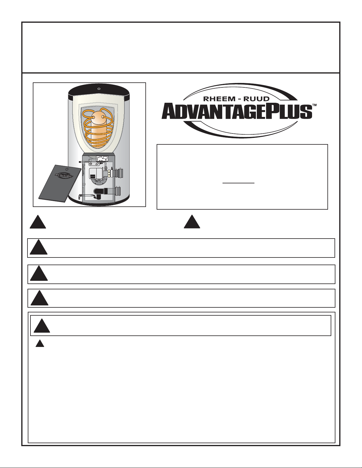
High Efficiency Commercial Gas Water Heater
USE & CARE MANUAL
WITH INSTALLATION INSTRUCTIONS FOR THE CONTRACTOR
This Use & Care Manual covers the following model numbers:
OFF
ON
Recognize this symbol as an Indication of Important
Safety Information!
!
NOTICE: This water heater is designed for use in a commercial application.The installation and
maintenance of it should be performed by qualified, licensed service personnel.
!
WARNING: Read and review this entire manual with special emphasis on the Venting and Operation
Sections prior to any installation work.
!
CALIFORNIA PROPOSITION 65 WARNING: This product contains chemicals known to the State of California
to cause cancer, birth defects or other reproductive harm.
!
WARNING: If the information in these instructions are not followed exactly, a fire or explosion may result
causing property damage, personal injury or death.
!
HE45-100N HE119-130N HE45-199LP
HE45-130N HE119-160N HE80-130LP
HE45-160N HE119-199N HE80-160LP
HE45-199N HE80-199LP
HE80-130N HE45-100LP HE119-130LP
HE80-160N HE45-130LP HE119-160LP
HE80-199N HE45-160LP HE119-199LP
Do Not Destroy this Manual. Please read carefully
and keep in a safe place for Future Reference.
!
FOR YOUR SAFETY!
!
— Do not store or use gasoline or other flammable
vapors or liquids or other combustible materials in
the vicinity of this or any other appliance.To do so
may result in an explosion or fire.
— WHAT TO DO IF YOU SMELL GAS
Do not try to light any appliance.
•
Do not touch any electrical switch; do not use any
•
phone in your building.
Printed in the USA
Immediately call your gas supplier from a neigh-
•
bor's phone. Follow the gas supplier's instructions.
If you cannot reach your gas supplier, call the fire
•
department.
Do not return to your building until authorized by
•
the gas supplier or fire department.
— Improper installation, adjustment, alteration, ser-
vice or maintenance can cause injury, property
damage or death. Refer to this manual. Installation
and service must be performed by a qualified
installer, service agency or the gas supplier.
AP12158-2 (04/05)
Page 2
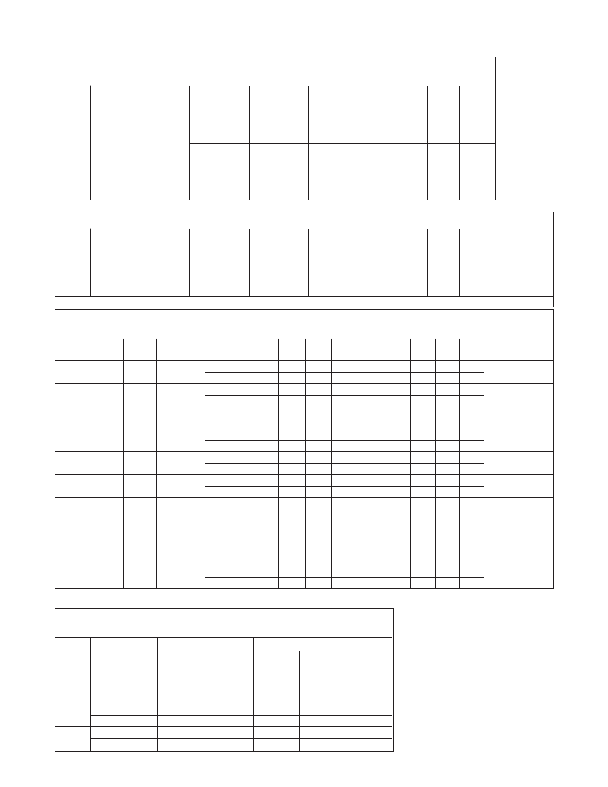
SPECIFICATIONS
RECOVERY CAPACITIES
Recovery in U.S. Gallons/Hr. (GPH) and Liters/Hr. (LPH) at Various Temperature Rises
MODEL INPUT (BTU/HR) THERMAL
NUMBER NAT. & LP EFFICIENCY UNITS
HE45-100
HE45-130
HE80-130
HE119-130
HE80-160
HE119-160
HE80-199
HE119-199
Recovery rating is based on thermal efficiencies obtained in an AGA certified laboratory.
BOOSTER MODELS
MODEL INPUT (BTU/HR) THERMAL
NUMBER NAT. & LP EFFICIENCY UNITS
HE45-160 160,000 95%
HE45-199 199,000 95%
All models exceed the minimum NAECA energy efficiency requirements of ASHRAE 90.1b-1989, 1992 requirements.
100,000 95%
130,000 95%
160,000 95%
199,000 95%
Recovery in U.S. Gallons/Hr. (GPH) and Liters/Hr. (LPH)
MAXIMUM DELIVERY
In U.S. Gallons and Liters
MODEL
NUMBER
HE45-100
HE45-130
HE80-130
HE119-130
HE45-160
HE80-160
HE119-160
HE45-199
HE80-199
HE119-199
All models have a maximum setpoint of 160°F with the exception of the HE45-160 and HE45-199 booster models. The HE45-160 and HE45-199 have a maximum setpoint of 180°F.
* NOTE: The 180º F models are shipped with all necessary components for an approved installation (see Booster Installation Kit for component list.)
GALLONS/
LITERS
MAX.
SETPOINT
45
45
80
45
80
45
80
160º 100,000
160º 130,000
160º 130,000
160º 130,000
180º* 160,000
160º 160,000
160º 160,000
180º* 199,000
160º 199,000
160º 199,000
170 55.6°C LTR. 156 192 228 265 337 446 555 991 1427
170 55.6°C LTR. 166 214 261 308 403 544 686 1253 1819
303 55.6°C LTR. 259 306 354 401 495 637 779 1345 1912
119
450 55.6°C LTR. 363 410 457 504 599 750 882 1449 2015
170 55.6°C LTR. 177 235 294 352 468 642 817 1514 2211
303 55.6°C LTR. 270 328 386 444 561 735 909 1607 2304
119
450 55.6°C LTR. 373 432 490 548 664 838 1013 1710 2408
170 55.6°C LTR. 192 264 336 408 553 770 987 1854 2721
303 55.6°C LTR. 284 357 429 501 646 863 1079 1947 2814
119
450 55.6°C LTR. 338 460 532 604 749 966 1183 2050 2918
(Includes useable storage and recovery for indicated times)
INPUT (BTU/HR)
NAT. & LP
DIMENSIONAL INFORMATION
All dimensions shown in English and Metric
MODEL
NUMBER UNITS
HE45-100
HE45-130
HE45-160
HE45-199
HE80-130
HE80-160
HE80-199
HE119-130
HE119-160
HE119-199
All models require a 120V power source.
* 130,000 Btu models are certified to be installed with 2” venting.
inches 42 23 1/2 32 2 1 1 175 lbs.
inches 42 23 1/2 32 3 1 1 175 lbs.
inches 72 23 1/2 32 3* 1-1/2 1-1/2 235 lbs.
inches 73 27 36 3* 1-1/2 1-1/2 405 lbs.
HEIGHT WIDTH DEPTH VENT
mm 1067 597 813 51 25 25 79 kgs
mm 1067 597 813 76 25 25 79 kgs
mm 1854 597 813 76 38 38 106 kgs
mm 1854 686 914 76 38 38 184 kgs
40°F 50°F 60°F 70°F 80°F 90°F 100°F 110°F 120°F
(22.2°C) (27.8°C) (33.3°C) (38.9°C) (44.4°C) (50.0°C) (55.6°C) (61.1°C) (66.7°C)
GPH 288 230 192 165 144 128 115 105 96
LPH 1090 872 726 623 545 484 436 396 363
GPH 374 299 249 214 187 166 150 136 125
LPH 1417 1133 944 809 708 630 567 515 472
GPH 461 368 307 263 230 205 184 167 154
LPH 1744 1395 1162 996 872 775 697 634 581
GPH 573 458 382 327 286 255 229 208 191
LPH 2169 1735 1446 1239 1084 964 867 789 723
40°F 50°F 60°F 70°F 80°F 90°F 100°F 110°F 120°F 130°F 140°F
(22.2°C) (27.8°C) (33.3°C) (38.9°C) (44.4°C) (50.0°C) (55.6°C) (61.1°C) (66.7°C) (72.2°C) (77.8°C)
GPH 461 368 307 263 230 205 184 167 154 142 132
LPH 1744 1395 1162 996 872 775 697 634 581 536 498
GPH 573 458 382 327 286 255 229 208 191 176 164
LPH 2169 1735 1446 1239 1084 964 867 789 723 667 620
TEMP. 5 10 15 20 30 45 1 2 3 MIN. TO RECOVER
RISE UNITS MIN. MIN. MIN. MIN. MIN. MIN. HR. HR. HR. CONTENTS
100°F GAL. 41 51 60 70 89 118 147 262 377
100°F GAL. 44 56 69 81 106 144 181 331 481
100°F GAL. 68 81 93 106 131 168 206 355 505
100°F GAL. 96 108 121 133 158 196 233 383 532
100°F GAL. 47 62 78 93 124 170 216 400 584
100°F GAL. 71 87 102 117 148 194 240 424 609
100°F GAL. 99 114 129 145 175 221 268 452 636
100°F GAL. 51 70 89 108 146 203 261 490 719
100°F GAL. 75 94 113 132 171 228 285 514 743
GAL. 102 121 141 160 198 255 312 542 771
100°F
WATER CONNECTIONS APPROX
INLET OUTLET
SHIPPING WT.
0" CLEARANCE TO
COMBUSTIBLES ON ALL
ADVANTAGE PLUS UNITS,
HOWEVER, A 24"
CONTROL PANEL SERVICE CLEARANCE IS
RECOMMENDED.
2
23
18
32
48
15
26
39
12
21
31
Page 3
General Safety Precautions
!
Be sure to read and understand the entire Use & Care Manual before attempting to install or operate this water heater.
Pay particular attention to the following General Safety Precautions. Failure to follow these warnings could result in a fire
or explosion, causing property damage, bodily injury or death. Should you have any problems understanding the instructions in this manual, STOP, and get help from a qualified installer or service technician or the gas supplier.
DANGER
WARNING
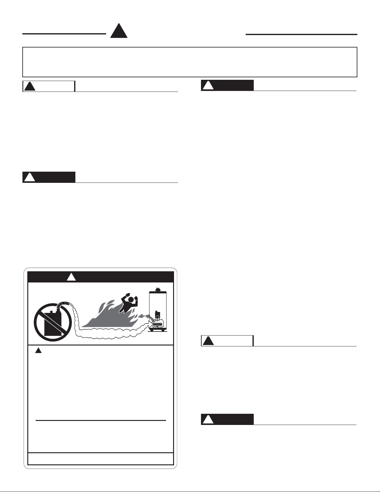
!
Gasoline, as well as other flammable materials and liq-
!
LIQUEFIED PETROLEUM MODELS
uids (adhesives, solvents, etc.), and the vapors they produce, are extremely dangerous. DO NOT handle, use or
store gasoline or other flammable or combustible materials anywhere near or in the vicinity of a water heater. Be
sure to read and follow the warning label pictured below
and other labels on the water heater, as well as the warnings printed in this manual. Failure to do so can result in
property damage, bodily injury, or death.
- Propane, or LP gas, must be used with great caution.
· It is heavier than air and will collect first in lower areas
making it hard to detect at nose level.
· Make sure to look and smell for LP leaks before
attempting to light appliance. Use a soapy solution to
check all gas fittings and connections. Bubbling at a connection indicates a leak that must be corrected. When
smelling to detect an LP leak, be sure to sniff near the
floor.
DANGER
!
· Gas detectors are recommended in LP applications and
their installation should be in accordance with the manuFailure to install and properly vent the water heater to the
outdoors as outlined in the Venting Section of this manual can result in unsafe operation of the water heater. To
avoid the risk of fire, explosion, or asphyxiation from car-
facturer's recommendations and/or local laws, rules, reg-
ulations or customs.
· It is recommended that more than one method be used
to detect leaks in LP applications.
bon monoxide, never operate this water heater unless it
is properly vented and has an adequate air supply for
IF LP GAS IS PRESENT OR SUSPECTED:
proper operation. Be sure to inspect the vent system for
proper installation at initial start-up and at least annually
thereafter. Refer to maintenance section of this manual
for more information regarding vent system inspections.
· DO NOT attempt to find the cause yourself;
· DO NOT try to light any appliance;
· DO NOT touch any electrical switch;
· DO NOT use any phone in your building.
!
DANGER
· Leave the house immediately and make sure your fam-
ily and pets leave also.
· Leave the doors open for ventilation and contact the gas
supplier, a qualified service agency or the fire depart-
ment.
· Keep the area clear until the service call has been
made, the leak is corrected, and a qualified agency has
FLAMMABLES
!
Vapors from flammable
liquids will explode and
catch fire causing death or
severe burns.
Do not use or store flammable
products such as gasoline,
solvents or adhesives in the
same room or area near the
water heater.
Keep flammable products:
1. far away from heater,
2. in approved containers,
3. tightly closed and
4. out of children's reach.
Installation:
Do not install water heater
where flammable products will
be stored or used unless the
main burner and pilot flames
Read and follow water heater warnings and instructions. If owners
manual is missing, contact the retailer or manufacturer.
Flammable Vapors
Water heater has a main
burner and pilot flame.
The pilot flame:
1. which can come on at
2. will ignite flammable
Vapors:
1. cannot be seen,
2. are heavier than air,
3. go a long way on the
4. can be carried from
flame by air currents.
are at least 18" above the
floor. This will reduce, but not
eliminate, the risk of vapors
being ignited by the main
burner or pilot flame.
any time and
vapors.
floor and
other rooms to the pilot
determined the area to be safe.
WARNING
!
Both LP and natural gas have an odorant added to help
detection. Some people may not physically be able to
smell or recognize this odorant. If unsure or unfamiliar
about the smell associated with LP or natural gas, ask
the gas supplier. Other conditions, such as "Odorant
Fade", which causes the odorant to "fade", or diminish in
intensity can also hide or camouflage a gas leak.
DANGER
!
Water heaters utilizing Liquefied Petroleum gas (LP) are
different from natural gas models. A natural gas heater
will not function safely on LP gas and vice versa. No
attempt should ever be made to convert a heater from
natural gas to LP gas. To avoid possible equipment dam-
3
Page 4
General Safety Precautions
!
age, personal injury or fire: DO NOT connect this water
heater to a fuel type not in accordance with unit rating
plate. Propane gas for propane units. Natural gas for
natural gas units. These units are not certified for any
other type fuel.
WARNING
!
LP appliances should not be installed below-grade (for
example, in a basement) if such installation is prohibited
by federal, state and/or local laws, rules, regulations, or
customs.
To meet commercial water use needs, the thermostat on
this water heater is adjustable up to 160
els have a maximum setpoint of 180°F). However, water
temperatures over 125
instantly or death from scalds. This is the preferred starting point for setting the controls for supplying general
purpose hot water.
Safety and energy conservation are factors to be considered when setting the water temperature on the thermostat. The most energy efficient operation will result when
the temperature setting is the lowest that satisfies the
needs consistent with the application.
!
DANGER
0
F can cause severe burns
0
F (Booster mod-
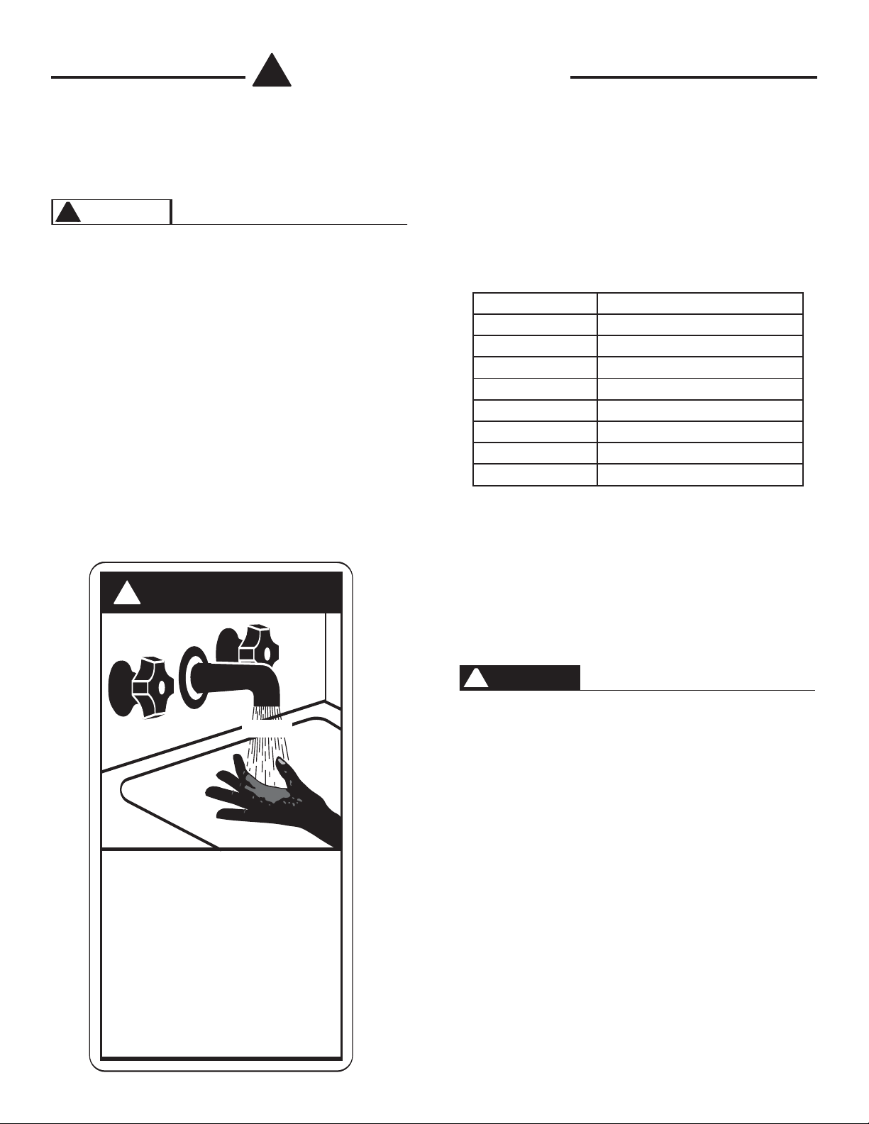
Maximum water temperatures occur just after burner has
shut off. To find temperature of the water being delivered, turn on a hot water faucet and place a thermometer in the hot water stream and read the thermometer.
The following chart details the relationship of water temperature and time with regard to scald injury and may be
used as a guide in determining the safest water temperature for your applications.
TIME / TEMPERATURE RELATIONSHIPS IN SCALDS
Temperature Time to Produce Serious Burn
120˚F More than 5 minutes
125˚F 1½ to 2 minutes
130˚F About 30 seconds
135˚F About 10 seconds
140˚F Less than 5 seconds
145˚F Less than 3 seconds
150˚F About 1½ seconds
155˚F About 1 second
Table courtesy of Shriners Burn Institute
The temperature of the water in the heater can be regulated by setting the temperature on the electronic thermostat. To comply with safety regulations, the thermostat
was set at its lowest setting before the water heater was
shipped from the factory. See the section titled SET
POINT ADJUSTMENT PROCEDURE to set the electronic thermostat.
HOT
BURN
Water temperature over 125°F can
cause severe burns instantly or
death from scalds.
Children, disabled and elderly are
at highest risk of being scalded.
See instruction manual before
setting temperature at water
heater.
Feel water before bathing or
showering.
Temperature limiting valves are
available, see manual.
DANGER
!
There is a Hot Water SCALD Potential if the thermostat is set too high.
NOTE: When this water heater is supplying general purpose hot water requirements for use by individuals, a
thermostatically controlled mixing valve for reducing point
of use water temperatures is recommended to reduce the
risk of scald injury. Contact a licensed plumber or the
local plumbing authority for further information.
4
Page 5

INSTALLATION
WARNING
!
Read and review this entire manual with special
emphasis on the Venting Sections and Operation
Sections prior to any installation work.
LOCAL INSTALLATION REGULATIONS
This water heater must be installed in accordance with
these instructions, local codes, utility company requirements, and/or in the absence of local codes, the latest
edition of the American National Standard / National Fuel
Gas Code, a copy of which can be purchased from either
American Gas Association, 1515 Wilson Blvd., Arlington,
VA 22209 as booklet Z223.1 or National Fire Prevention
Association, 1 Batterymarch Park, Quincy, MA 02269 as
booklet NFPA 54.
The water heater must be located or protected so it is not
subject to physical damage, for example, by moving
objects, area flooding, etc.
CAUTION
!
The water heater should not be located in an area
where leakage of the tank or connections will result
in damage to the area adjacent to it or to lower floors
of the structure. When such areas cannot be avoided, it is recommended that a suitable catch pan, adequately drained, be installed under the water heater.
The pan MUST NOT restrict the flow of combustion
air flow.
NOTE: Auxiliary catch pan installation MUST conform to the applicable local codes
service clearance minimum. This front service may be
achieved by a non-rated or combustible door or access
panel; providing the 24" service clearance is achieved
when the door is opened or panel is removed. This water
heater must not be located near flammable liquids
such as gasoline, adhesives, solvents, paint thinners, butane, liquefied propane, etc. as the controls
of this appliance could ignite those vapors, causing
an explosion.
TEMPERATURE AND PRESSURE RELIEF VALVE
A new combination temperature and pressure relief
valve, complying with the Standard for Relief Valves and
Automatic Gas Shutoff Devices for Hot Water Supply
Systems, ANSI Z21.22, must be installed in the opening
provided on the water heater at the time of installation.
No valve is to be placed between the relief valve and the
water heater. For circulating tank installation, the separate storage tank(s) must have similar protection. The
pressure rating of the relief valve must not exceed the
maximum working pressure as marked on the front of the
water heater. The Btu/h rating of the relief valve must
equal or exceed the Btu/h input of the water heater as
noted on its rating plate. Connect the outlet of the relief
valve to a suitable open drain. The discharge line must
pitch downward from the valve to allow complete draining
(by gravity) of the relief valve and discharge line, and
must be no smaller than the outlet of the relief valve. The
end of the discharge line should not be threaded or concealed and should be protected from freezing. No valve
of any type, restriction or reducer coupling should be
installed in the discharge line. Local codes shall govern
the installation of the relief valves.
LOCATION
Choose a location for your water heater centralized to the
piping system, along with consideration to vent pipe
length. As the length of vent pipe increases, the firing
rate of the appliance decreases. You must also locate
the Advantage Plus where it will not be exposed to below
freezing temperatures. Additionally, you will need to
place the water heater so that the controls, drain,
inlet/outlet, and gas valve are easily accessed. This
appliance must not be installed outdoors, as it is certified
as an indoor appliance, and must be kept vertical and on
a level surface. Also, care must be exercised when
choosing the location of this appliance where leakage
from the relief valve, leakage from related piping, or leakage from the tank or connections, will not result in damage to the surrounding areas or to the lower floors of the
building. A water heater should always be located in
an area with a floor drain or installed in an adequately drained catch pan suitable for water heaters.
Proper clearance must be provided around the
AdvantagePlus as follows: Sides, bottom, top, and back
are 0" (zero clearance). Front of the appliance needs 24"
EXPANSION TANK
A potable hot water expansion tank may be required to
offset the water expansion as the water is heated. In
most city plumbing systems, the water meter has a no
return or back flow device built into the system to prevent
back flowing of water back into city mains. Back flow preventers may be found on all incoming water supplies.
Under these circumst
expansion tank listed for potable water use. The expansion tank should be located on the cold inlet piping close
to the water heater. The expansion tank must be suit-
able for hot potable water.
WARNING
!
The manufacturer’s warranty does not cover any
damage or defect caused by installation or attachment or use of any special attachments such as energy saving devices (other than those authorized by
the manufacturer) into, onto, or in conjunction with
the water heater. The use of such unauthorized
5
ances, you will need a hot water
Page 6
devices may shorten the life of the water heater and
may endanger life and property. The manufacturer
disclaims any responsibility for such loss or injury
resulting from the use of such unauthorized devices.
DOMESTIC WATER CONNECTIONS
The water connections must be installed in accordance
with all national and local plumbing codes, or any prevailing standard. NEVER USE DIELECTRIC UNIONS
OR GALVANIZED STEEL FITTINGS ON ADVANTAGE
PLUS CONNECTIONS. The inlet and outlet connections
are 1" on the 45 gallon models and 1-1/2" on the 80 and
119 gallon models. On the cold inlet, install a 1" brass
tee on the 45 gallon models, or a 1-1/2" brass tee on the
80 and 119 gallon models. On the run of the 1" brass tee
install, with pipe sealant, compound a 1" brass drain cock
or it's equivalent (not supplied). Into the branch of the 1"
or 1-1/2" brass tee install a copper male adapter to match
with the copper plumbing system. For convenience, you
may install a shut off valve and a union in the cold inlet
piping to ease servicing in the future. If there is a back
flow preventer, or any type of a no return valve in the system, then you must install an additional tee for a suitable
potable thermal expansion tank. (See section on
Expansion Tank.) In the hot outlet connection, (top left),
install a suitable adapter to match the copper tubing of
the plumbing system. A thermal trap or heat trap loop
may be installed here to provide additional energy savings and prevent thermal siphoning of domestic hot
water. A domestic hot water tempering/ anti-scald valve
should be installed into the hot water line to prevent the
maximum outlet water temperature from exceeding 125°
Fahrenheit to prevent scald injury.
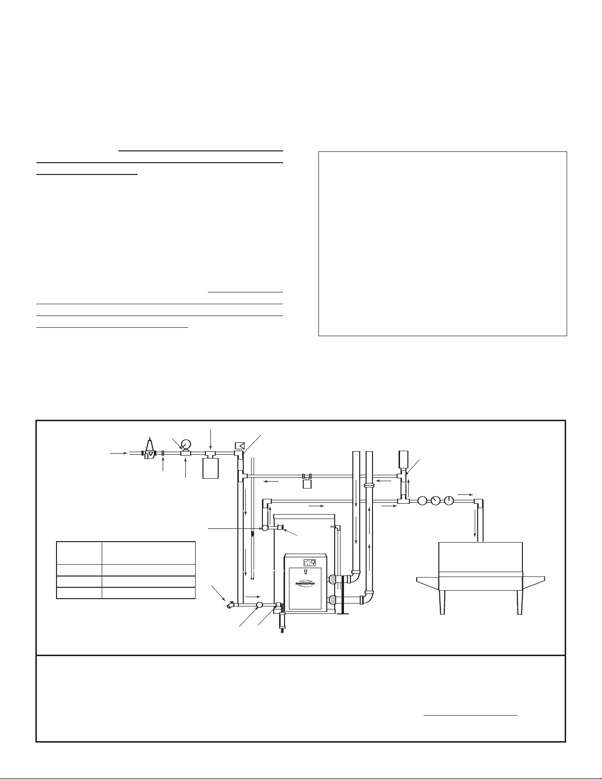
SPECIAL INSTRUCTIONS FOR BOOSTER
INSTALLATIONS
All booster heaters are supplied with the "Booster
Installation" kit. In order to maintain proper temperature,
this kit must be correctly installed. The Booster kit contains the following list of parts:
#01 - Nibco Tee - 1"x 1"x 1/2" (2 pcs.)
#02 - Female Adapter - 1" (2 pcs.)
#03 - Dial Thermometer (2 pcs.)
#04 - Expansion Tank - 4-1/2 Gal.
#05 - Grundfos 3 Speed Pump w/ Check Valve
#06 - Nibco 1.2" x 12" Fitting Air Chamber
#07 - Vacuum Relief Valve
#08 - Pressure Gauge - 0 - 200 PSI
#09 - Nibco Tee 712R - 1"x 1" x 3/4" (2 pcs.)
#10 - Nibco Tee 714RR - 1"x 1/2"x 1"
#11 - Nibco Tee - 1"x 1/2"x 1" Copper
#12 - Reducing Coupling
#13 - Pressure Reducing Valve
#14 - Nibco Male Adapter - 1"
See the following drawing for a typical "Booster" installation. Please note that those items marked with an asterisk in the drawing are not included with the Booster kit,
but are items that should be installed in a typical dishwasher package.
120˚ F TO
140˚ F SUPPLY
1" COPPER
CIRCULATOR
SETTING
1
2
#08
#12
#13
#14
#09
#01
#03
DISTANCE TO DISHWASHER
(ONE WAY)
1 - 19 FT.
20 - 59 FT.
DRAIN
VALV E
#09
#04
1" SUPPLY
#07
#11
3/4" GAS
3/4" RETURN
3 60 - 100 FT.
#01
#02
#03
The booster heater is equipped with a circulating pump to provide the
minimum water flow in the booster and maintain a uniform water temperature in the tank. Depending on the physical distance from the
booster to the dishwasher, and the length of time between washes, it
may be necessary to run an empty rack to purge the supply line of
water that has cooled below 180ºF. For this reason it is best to locate
the booster as close as possible to the dishwasher. The circulator is
equipped with three speeds to increase flow rate and reduce heat
CONDENSATE
DRAIN
1" SUPPLY
3" PVC
180˚F
RETURN
3" ABS MIN.
#06
180˚F
WATER
84" REQ'D
#10
* PRESS. REGULATOR
* PRESS. GAUGE
* THERMOMETER
DISHWASHER
ances should the
3" PVC
#05
#02
INTAKE
EXHAUST
loss. Reference the "Distance" chart to determine the appropriate circulator speed setting.
All piping should be installed with suitable pipe insulation to avoid
temperature loss on the re-circulation line. A minimum of 1" thick pipe
insulation is recommended. Under no circumst
booster be installed without a circulating pump.
6
Page 7
WARNING
!
Tank MUST be full of water before power is turned
on. Heat exchanger coil WILL BE DAMAGED if energized even for a short time while the tank is dry. The
water heater’s warranty does not cover damage or
failure resulting from operation with an empty or partially empty tank. (Reference is made to the limited
warranty for complete terms and conditions)
ELECTRICAL CONNECTION
The electrical connection for the AdvantagePlus is on the
left side of the combustion shroud. There is a 1/2" knockout location for electrical connection. All electrical wiring
must be performed by a qualified licensed electrician,
and in accordance with National Electrical Code, or to the
applicable local codes and standards. The electrical
requirements are for standard 120 volts, 60 Hz., 10 amp
service. It is recommended that an electrical disconnect
switch be placed near the water heater, and that the connection to the AdvantagePlus be made using 3/8" extraflex, or 3/8" greenfield (or equivalent). This unit must be
wired with #14 AWG, and fused for no more than 15
amps.
properly grounded! Ground the water heater by con-
necting the green wire in the electrical access compartment directly to the main building ground system. It is
very important that the building system ground is
inspected by a qualified electrician prior to making
this connection. Once all connections have been
made, the electrical access may be closed. It is very
important that the electrical power is not turned on until
gas and venting connections are completed and the tank
is full of water.
A green LED is provided on the main control board.
This LED must be illuminated when appliance is
turned on for proper operation. Failure to illuminate
means bad or missing ground or reverse polarity.
GAS CONNECTION
Gas supply shall not exceed a maximum inlet pressure of
14" water column (350 mm), 1/2 pound pressure (3.4
kPa), and a minimum of 7" water column (natural and
propane). The entire piping system, gas meter, and regulator must be sized properly to prevent a pressure drop
greater than 0.5" of water column as stated in the
National Fuel Gas Code. Gas pressure information is
listed on the rating plate. It is very important that you
are connected only to the type of gas noted on the
rating plate; "LP" or propane gas or "Nat" natural
gas or city gas. All gas connections must be approved
by the local gas supplier or utility in addition to the governing authority prior to turning the gas supply on. The
nipple provided for the inlet gas connection is 1/2", and it
is mandatory that a 3/4" to 1/2" reducing bushing (provided) is used, threaded into the branch of a 3/4" tee, and
a drip leg fabricated, as per the National Fuel Gas Code.
It is of extreme importance that this unit be
You must ensure that the entire gas line to the reducing bushing connection at the Advantage Plus is no
smaller than 3/4".
CAUTION
!
THE USE OF FLEXIBLE GAS CONNECTORS IS NOT RECOMMENDED. HOWEVER, IF USED, IT IS IMPERATIVE THAT THEY ARE
SIZED CORRECTLY. FLEXIBLE GAS CONNECTORS MUST HAVE A
MINIMUM ID OF 3/4". A MINIMUM 3/4" ID MUST BE MAINTAINED
TO AVOID RESTRICTION OF GAS FLOW! NEVER REDUCE THE
GAS SUPPLY LINE BELOW 3/4"!
Once all the inspections have been performed, the piping
system must be leak tested. If the leak test pressure is
higher than the maximum permissible inlet pressure, you
must isolate the AdvantagePlus from the gas line before
testing. In order to do this, you must disconnect the
union and cap the inlet gas line. In the event the gas
valve is exposed to a pressure greater than 1/2 PSI, 14"
water column, the gas valve must be replaced.
Failure to follow all precautions could result in fire,
explosion or death! It is recommended that a soapy
solution be used to detect leaks. Bubbles will appear and
indicate a leak is present. The gas piping must be sized
for the proper flow and length of pipe to avoid unacceptable pressure drop. Both the gas meter and the gas regulator must be properly sized for the total gas load. If you
experience a pressure drop greater than 1" W.C., the
meter or regulator or gas line may be undersized or in
need of service. On the inlet side of the gas valve, there
is a 1/8" NPT plug. This plug can be removed to attach a
manometer. You can attach a meter to the incoming gas
drip leg by removing the cap and installing the meter. The
gas pressure must remain between 7" and 14" of water
column during stand-by and unit running heat cycle. If an
in-line regulator is used, it must be a minimum of 10 feet
from the AdvantagePlus. It is very important that the
gas line is properly purged by the gas supplier or
utility. Failure to properly purge the lines or improper line sizing, will result in the failure of the
AdvantagePlus lighting off. The gas valve is a special
gas valve which has a Pressure Augmented Regulator
feature, as well as negative outlet pressure. This valve
must not be replaced with a conventional valve under any
circumstances. Make sure valve is in the “OFF” position
prior to turning gas supply on. As an additional safety
feature, this valve has a left hand thread on the outlet
end, and a special tamper resistant electrical connector.
WARNING
!
Never use open flame to test for gas leaks, as
bodily injury or property damage could result.
WARNING
!
DO NOT exceed input shown on water heater rating
plate.
7
Page 8

VENTING WHEN USING 3" VENT PIPE
(ONLY MODELS WITH INPUTS OF 100,000 BTU AND 130,000 BTU
ARE CERTIFIED TO USE 2" VENT PIPE, SEE SPECIAL VENTING
INSTRUCTIONS SECTION)
For inlet air supply, top pipe on the right of the shroud,
use 3" PVC schedule 40. It is very important that you plan
the location properly to eliminate long pipe runs and
excessive fittings. Inlet pipe size must not be reduced.
Do not combine the inlet air with any other inlet pipe
including an inlet to an additional similar appliance.
The joints must be properly cleaned, primed, and
cemented. The piping must also be properly supported
as per local and national standard plumbing codes. It is
important that the piping be clean and free from burs,
debris, ragged ends, and particles of PVC.
For exhaust piping, lower pipe on the right of the shroud,
use only ABS schedule 40 or CPVC schedule 40 or 80,
NON FOAM CORE
, in the first 84" (7 feet) of vent length.
The balance of the inlet and exhaust piping may be PVC
schedule 40, ABS schedule 40 or CPVC schedule 40 or
80, NON FOAM CORE ONL
Y, as required to meet local
venting codes.
Exhaust piping should be sloped back to the connection
on the AdvantagePlus, at least 1/4 inch per foot of pipe,
to remove the condensate that forms within the pipe. The
total combined length of pipe, (inlet air piping plus
exhaust piping) including allowances for elbows, should
not exceed 85 equivalent feet. The total combined length
of pipe, including allowances for elbows, should not be
less than 22 equivalent feet (minimum length of 12 feet of
piping, including allowances for elbows, on the inlet and
the exhaust). Choose your vent termination locations
carefully. You must make certain that exhaust gas does
not re-circulate back into the air inlet pipe. You must
place your vent terminations in an open area, according
to the following guidelines.
V
enting Guidelines
1) Never vent into a walkway or patio area, or an alley,
or otherwise public area less than 7' from the ground.
2) Allow four (4) feet below or four (4) feet horizontally
from any door, window or gravity air inlet to the building
or other appliance.
3) Never install a heat saver or similar product to capture waste heat from exhaust.
4) Always have vent location at least 1' above maximum
snow level.
5) Always have vent 1' above ground level, away from
shrubs and bushes.
6) Follow local gas codes in your region or refer to
National Fuel Gas Code, or Can B149.
7) Always have vent at least 3' from an inside corner of
outside walls.
8) Maintain at least 4' clearance to electric meters, gas
meters and exhaust fans or inlets.
9) Inlet air must be taken from outside of building next
to exhaust outlet, no closer than 8".
10) Always place 1/2 inch x 1/2 inch 16 gauge galvanized steel screen in the intake and exhaust openings to
prevent foreign matter from entering the AdvantagePlus.
11) The vent system must be balanced by friction loss
equivalent (See table on page 10).
12) The same method must be used for both intake and
exhaust termination. DO
NOT terminate one horizontal-
ly and the other vertically.
13) Roof Venting: The vent intake and exhaust must be
properly cleaned and glued, for pressure tight joints.
Several methods for venting the AdvantagePlus can be
found on pages 22 and 23. Use the layout as a guideline. Certain site conditions such as multiple roof
lines/pitches may require venting modifications-consult
factory. The air inlet must be a minimum of 1' vertically
above the maximum snow level or 24" whichever is
greater. The air inlet must also be a minimum of 10' horizontally from the roof and terminated with a tee. The
exhaust must be a minimum of 24" above the air inlet
opening and terminated with a coupling. It is very important that there are no other vents, chimneys, or air inlets
in any direction for at least 4'. All venting must be
properly supported, as the AdvantagePlus is not
intended to support any venting whatsoever. All pip-
ing, glue, solvents, cleaners, fittings, and components
must conform to ASTM (American Society for Testing and
Materials), and ANSI (American National Standard
Institute).
14) It is recommended that you use vent kits specifically
designed for AdvantagePlus installations.
PIPE / FITTINGS WHEN USING 3” VENT PIPE
The first 84" (7’) of exhaust piping, must be of 3" ABS
solid only (provided) or CPVC; (NEVER use cellular
foam core pipe on exhaust piping), and conform to
ASTM D-3965 for ABS or ASTM F-441 for CPVC, and fittings to ASTM D2661 & D3311 for ABS and ASTM F-439
for CPVC. The balance of exhaust piping, and all of
intake piping, use standard 3" PVC schedule 40 or 3"
ABS schedule 40, conforming to ASTM D2665, or ABS
conforming to ASTM D-3965 & ASTM R-441 for ABS; and
fittings conforming to ASTM D-2665 & D331. ABS may
also be used for intake venting as long as pipe conforms
to ASTM D3965 & D2661 and fittings meet ASTM D2661
& D3311.
FOR LONGER VENT LENGTHS WHEN USING 3”
VENT PIPE
All venting must be 3", both intake and exhaust. NEVER
use any piping less than 3", or different size pipe on
the intake and exhaust. You may use 4" venting on
both intake and exhaust to lower the pressure drop and
provide additional venting length. It is imperative when
using 4" venting to follow these instructions very
carefully. For longer venting lengths, the first 10' of
both the intake and exhaust piping are 3". For the
intake, use 10' of 3" PVC plus one 90 degree or two
45 degree elbows. For the exhaust, use 10' of ABS
solid NON FOAM CORE, or CPVC plus one 90 degree
8
Page 9

or two 45 degree elbows. Then use a 4" x 3" PVC or 4"
x 3" ABS reducing coupling. Then proceed with PVC 4"
NON FOAM CORE pipe and fittings for both the intake
and exhaust piping. On 4" piping you may go an additional 125 equivalent feet of pipe and fittings, combined
total length. The 4" fittings have a friction loss allowance
as follows:
4" 90 degree = 3' and a 4" 45 degree = 1'.
The total maximum venting length can be 125', plus the
first 10' of each 3", and a maximum fitting allowance of
the 3", total two 90 degree or four 45 degree before
increasing to 4". Total equivalent would be 30' of 3" plus
125' of 4". Never
use different pipe sizes for intake and
exhaust.
SPECIAL VENTING INSTRUCTIONS USING 2" VENT
PIPE
(ONLY MODELS WITH INPUTS OF 100,000 BTU AND 130,000 BTU
ARE CERTIFIED FOR 2" VENTING) HE45-100, HE45-130, HE80-130,
HE119-130
For inlet air supply, top pipe on the right of the shroud,
use 2 inch PVC schedule 40. It is very important that you
plan the location properly, to eliminate long pipe
runs and excessive fittings. Inlet pipe size must not be
reduced. Do not combine the inlet air with any other inlet
pipe, including an inlet to an additional similar appliance.
The joints must be properly cleaned, primed and cemented. The piping must also be properly supported as per
local and national standard plumbing codes. It is important that the piping be clean and free from burs, debris,
ragged ends and particles of PVC.
For exhaust piping, lower pipe on the right of the shroud,
use 2 inch PVC schedule 40 NON FOAM CORE. Use 2
inch ABS NON FOAM CORE or 2 inch CPVC schedule
40 or 80 only when required to meet local venting codes.
Exhaust piping should be sloped back to the connection
on the AdvantagePlus, at least 1/4 inch per foot of pipe,
to remove the condensate that forms within the pipe. The
total combined length of pipe, (inlet air piping plus
exhaust piping) including allowances for elbows, should
not exceed 85 equivalent feet. The total combined length
of pipe, including allowances for elbows, should not be
less than 22 equivalent feet (minimum length of 12 feet of
piping, including allowances for elbows, on the inlet and
the exhaust). Choose your vent termination locations
carefully. You must make certain that exhaust gas does
not re-circulate back into the air inlet pipe. You must
place your vent terminations in an open area, according
to the venting guidelines section on page 8.
PIPE / FITTINGS WHEN USING 2" VENT PIPE
All inlet air and exhaust venting may use standard PVC
schedule 40 piping, conforming to ASTM D-1785, and fittings conforming to ASTM D-2466, or ABS pipe conforming to ASTM D-3965 and ASTM D-2661, and fittings conforming to ASTM D-3311 and ASTM D-2661. (NEVER
use cellular foam core pipe on exhaust piping)
FOR LONGER VENT LENGTHS WHEN USING
2" VENT PIPE
You may use 3 inch venting on both the intake and
exhaust to lower the pressure drop and provide additional vent length. It is imperative when using 3 inch venting
to follow these instructions carefully. For longer vent
lengths, the first 10 feet of both the intake and exhaust
piping must be 2 inches. For the first 10 foot use 2 inch
PVC schedule 40 NON FOAM CORE, 2 inch ABS NON
FOAM CORE or 2 inch CPVC schedule 40 or 80 plus one
90 degree or two 45 degree elbows. Then use a 2" x 3"
reducing coupling of like material. Then proceed with 3
inch PVC schedule 40 NON FOAM CORE, 3 inch ABS
NON FOAM CORE or 3 inch CPVC schedule 40 or 80
pipe and fittings for both the intake and exhaust piping.
On 3 inch pipe you may go an additional 125 equivalent
feet of pipe and fittings, combined total length. The total
combined equivalent vent length would be 30 equivalent
feet of 2-inch vent and 125 equivalent feet of 3-inch vent,
for a maximum equivalent vent length of 155 feet. Never
use different pipe sizes for intake and exhaust.
CLEANER / CEMENT
Cement for all venting must be ALL PURPOSE Cement,
and must conform to ASTM D-2235, D-2564 and F-493,
and cleaner for the piping and fittings must conform to
ASTM F-656.
NOTE
:
THE METHODS DESCRIBED ARE SUGGESTED
GENERIC METHODS ONLY. SPECIFIC JOB SITE
OBSERVATIONS AND SIZING MAY REQUIRE ALTERNATE INSTALLATION METHODS. CONSULT THE
FACTORY WITH SPECIFIC JOB REQUIREMENTS
FOR ADDITIONAL RECOMMENDATIONS.
VERY IMPORTANT SET-UP INSTRUCTIONS!
IF YOU HAVE A COMBUSTION ANALYZER, THE FOLLOWING RATINGS WILL BE VERY HELPFUL IN SETTING UP YOUR ADVANTAGE PLUS:
FOR NATURAL GAS -
CO2reading should be between (9 1/2% – 10%)
O2reading should be between (3 1/2% – 4 1/2%)
CO reading should be under 10 PPM
FOR PROPANE GAS -
CO2reading should be between (10 1/2% – 11 1/2%)
O2reading should be between (3 1/2% – 4 1/2%)
CO reading should be under 10 PPM
9
Page 10

FRICTION LOSS EQUIVALENCE TABLES
R
3" VENTED MODELS 2" VENTED MODELS
FITTING
DESCRIPTION
3" 90˚ 4" 90˚
3" 45˚
3" Coupling
3" Tee
3" Pipe
3" Concentric vent kit
3" V1000 vent kit
EQUIVALENT
FEET OF PIPE
5'
3'
0'
0'
1' = 1'
3'
0'
FITTING
DESCRIPTION
2" 90˚
2" 45˚
2" Coupling
2" Tee
2" Pipe
2" Concentric vent kit
EQUIVALENT
FEET OF PIPE
5'
3'
0'
0'
1' = 1'
3'
AFTER THE FIRST 10' OF 3" ONLY
4" EQUIVALENT TABLE
FITTING
DESCRIPTION
4" 45˚
4" Coupling
4" Tee
4" Pipe
VENTING EXAMPLES (NOTE: SHOWN AS INTAKE & EXHAUST PIPE FITTINGS ADDED TOGETHE
* = MINIMUM VENT LENGTH ** = MAXIMUN VENT LENGTH
GRAND TOTAL
TOTAL COMBINED
VENT LENGTH
(FEET) INTAKE &
EXHAUST
*12
20
20
20
20
20
20
20
20
20
20
20
20**
30
30
30
30
30
30
30
30
30**
40
40
40
40
40
40
40**
50
50
50
50
50**
60
60
60**
70**
QTY. OF 90˚
ELBOWS
2
2
3
4
5
6
7
8
9
10
11
12
13
3
4
5
6
7
8
9
10
11
3
4
5
6
7
8
9
3
4
5
6
7
3
4
5
3
EQUIVALENT
FRICTION LOSS
(FEET) FOR EACH
ELBOW
5
5
5
5
5
5
5
5
5
5
5
5
5
5
5
5
5
5
5
5
5
5
5
5
5
5
5
5
5
5
5
5
5
5
5
5
5
5
TOTAL FRICTION
LOSS FOR
ELBOWS
10
10
15
20
25
30
35
40
45
50
55
60
65
15
20
25
30
35
40
45
50
55
15
20
25
30
35
40
45
15
20
25
30
35
15
20
25
15
VENT LENGTH
(FEET) WITH
FITTING FRICTION
LOSS ADDED
22
30
35
40
45
50
55
60
65
70
75
80
85**
45
50
55
60
65
70
75
80
85**
55
60
65
70
75
80
85**
65
70
75
80
85**
75
80
85
85
EQUIVALENT
FEET OF PIPE
3'
1'
0'
0'
1' = 1'
10
Page 11

OPERATION
CONTROL DESCRIPTION
The fully integrated water heater control is an all electronic, fully automatic controller which will provide many
years of trouble free service. The control requires no
periodic maintenance and includes a built-in microprocessor which performs a number of diagnostic tests to
verify proper appliance and control operation. Should an
unsafe condition occur, the burner will shut down and the
appropriate status indicators will illuminate indicating the
need for service. Consisting of two printed circuit board
assemblies, the controller's main board is attached to the
inside left of the shroud while the display board is mounted to the front top of the shroud. This arrangement simplifies access for the user adjustments while enhancing
the visibility of the temperature display and status indicators. A power step-down transformer and blower pressure switch are also mounted on the inside left of the
shroud. The controller display functions include a high
visibility three digit LED readout which is used to display
the actual water temperature within the tank along with
the programmed desired water temperature (set point
temperature). Nine individual LED indicators are also
mounted on the display board which are used to determine the operating status of the appliance and provide
assistance when troubleshooting any problems which
may occur. All indicators are of the solid state variety and
should last for the life of the appliance. The controller
has sufficient built-in memory to retain the programmed
temperature set point in the event power is ever interrupted. The final component of the control system
includes a temperature sensing probe which is threaded
into the side of the tank. This probe is of unique construction in that both the temperature sensing/control and
safety limit functions are performed by this single device.
All probe components are of solid state construction to
provide extended operational life.
START UP PROCEDURE
(NEVER APPLY POWER TO AN ADVANTAGEPLUS
UNIT THAT IS NOT COMPLETELY FILLED WITH
WATER)
1. Make sure that the AdvantagePlus has been installed
to these instruction procedures along with all applicable
state and local codes.
2. Make sure all gas piping and connections have been
verified and inspected by all applicable inspectors. Turn
on gas supply. Ensure that the gas line and the LP tank,
if applicable, has been properly purged. Failure to properly purge the gas lines will result in failure to
operate.
3. Make sure that the cold water supply has been turned
on and the AdvantagePlus is completely filled with water.
Verify by opening a hot water faucet, or purging at the
dishwasher, and allowing water to flow until all air is
removed and a clear water flow is present.
.
VALVE.
0
F and
0
F and
NEVER PURGE FROM THE T&P
4. Turn on electrical supply.
5. The control will first display "102", then "88.8", which is
the control test, and finally the actual tank temperature at
the probe.
TEMPERATURE SET POINT ADJUSTMENT
PROCEDURE
WARNING
!
When this water heater is supplying general purpose
hot water requirements for individuals, a thermostatically controlled mixing valve for reducing point of
use water temperature is recommended. Contact a
licensed plumber or the local plumbing authority for
further instructions.
The three digit LED display will illustrate actual water
temperature within the tank under normal operating conditions. However, this display is also used to indicate the
temperature set point when in the programming mode.
The controller has a temperature set point range of 70°F
to 160°F (Booster models have a maximum set point of
180°F), with a factory setting of 120°F.
NOTE: Power must be applied to the controller prior
to any programming operations.
To change or access the programmed temperature set
point value, utilize the red button on the display panel.
Momentarily depressing the button will briefly illustrate
the existing set point value. If the button is held down for
more than one second, the programming mode is
entered and the set point value will begin incrementing by
one degree per second. When the desired set point
value is reached, simply release the button and the controller will automatically retain this value in temporary
memory. After 30 seconds, this new set point will be
retained in permanent memory
NOTE: If power is interrupted during this 30 second
period, the new set point will not be retained in permanent memory. It is a good practice to re-check the
set point value approximately 60 seconds after a new
value has been entered.
If the button is held down, the maximum set point will
reach 160°F (180°F on Booster models) and stop. This is
the maximum value. At this point, if the desired set point
has not been obtained, release the button and depress it
again, the set point will decrement down to 70
stop. The set point value will now restart at 70
once again increase in value for as long as the button is
pressed.
11
Page 12

DANGER
CAUTION
!
!
There is a hot water SCALD POTENTIAL if the
thermostat is set too high.
THERMOSTAT DIFFERENTIAL ADJUSTMENT
PROCEDURE
8. If flame is present, the control will enter the heating
mode where it will continue heating the tank water until
the set point temperature plus 4°F is reached. At this
point, the gas valve is closed and the control enters the
post-purge cycle. The flame can be viewed through a
window on the lower right of combustion blower flange.
To allow proper water heater operation, the control has
an 8°F "window" around the set point. This means that
the burner will be turned on when the water temperature
drops to 4°F below the set point, and it will be turned off
when the water temperature reaches 4°F above the set
point. Thus, if the set point is set to 120°F., the control
will turn on the burner when the water temperature drops
to 116°F., and will continue to heat the water until the
temperature reaches 124°F. The differential is factory set
to 8°F (+ or- 4°F.) If another differential is required, the
value of the differential can be field adjusted by holding
the set point button when power is applied to the control.
Shut off power to the control. Next hold in the set point
button. Now reapply power to the control. Using the set
point button, the value of the differential can be incremented or decremented as above. When the proper
value is reached, release the button and wait for the display to show "00". This indicates the new differential has
been stored into permanent memory. Remove power
and restart control by applying power for normal operation.
OVERALL APPLIANCE AND CONTROL OPERATION
9. The post purge cycle continues to run the combustion
blower for an additional 30 seconds to purge the system
of all combustion gases. After this time period, the blower is de-energized and will coast to a stop.
10. The control will now enter the idle state while continuing to monitor internal tank water temperature. If the
temperature drops to 4°F below the set point value, the
control will automatically return to step 1.
STATUS INDICATORS
Pages 16-20 contain nine individual diagrams which illustrate the various operating states of the appliance and
their relation to the LED status indicators found on the
controller. These diagrams reflect normal water heater
operation.
MAINTENANCE
In unusually dirty or dusty conditions, care must
be taken to keep appliance door in place. Failure
to do so VOIDS WARRANTY!
A normal operating sequence is as follows:
1. The control determines that the actual water temperature inside the tank is 4 degrees F below the programmed temperature set point.
2. The control performs selected system diagnostic
checks.
3. If all checks are successfully passed, the combustion
blower is energized for the 40 second pre-purge cycle.
4. After the pre-purge cycle is complete, power is applied
to the ignitor element for the ignitor warm-up period
(blower should continue to run).
5. The ignitor warm-up period will last for 30 seconds,
then gas valve will be opened, allowing gas to enter the
burner chamber.
6. The ignitor will remain on for an additional 4 seconds,
then it will be turned off.
7. After an additional 2 seconds, the control will verify the
presence of flame. If the flame was not established, the
gas valve will be closed, power will be removed from the
ignitor element, and the control will run the blower for 30
seconds. This removes excess fuel from the combustion
chamber. At this point, the control will return to step 2.
The control system requires no periodic maintenance
under normal conditions. However, in unusually dirty or
dusty conditions, periodic vacuuming of the cover to
maintain visibility of the display and indicators is recommended.
INTERNAL WIRING
For specific wiring information, please refer to the diagrams on pages 21 and 22.
SHUTDOWN PROCEDURE
If the burner is operating, lower the set point value to
70°F and wait for the burner to shut off. Continue to wait
for the combustion blower to stop so all latent
combustion gases are purged from the system.
This should take a maximum of 40 to 90 seconds.
Disconnect the electrical supply. If the burner is not operating, disconnect the electrical supply.
VACATION PROCEDURE
If there is danger of freezing, change the set point to
70°F. DO NOT
danger of freezing, follow the "Shutdown Procedure".
12
turn off electrical power. If there is no
Page 13

FAILURE TO OPERATE
CORROSIVE ATMOSPHERES
Should the burner fail to light, the control will perform two
more ignition trials prior to entering a lockout state (flashing “LOC”). Note that each subsequent ignition trial will
not occur immediately. After a failed ignition trial, the
blower must run for approximately 10 seconds to purge
the system, then the ignitor element must complete a 30
second warm-up period. Therefore, a time period of
approximately 40 to 90 seconds will expire between each
ignition trial. If the burner lights during any one of these
three ignition trials, normal operation will resume. If the
burner lights, but goes off in about 4 seconds, check the
polarity of the wiring. See electrical on page 6. If the
burner does not light after the third ignition trial, the
control will enter a lockout state. This lockout state
indicates that a problem exists with either the appliance, the controls, or the gas supply. Under such cir-
cumstances, a qualified service technician should be
contacted immediately to properly service the appliance
and correct the problem. If a technician is not available,
depressing the red button once will remove the lockout
state so additional trials for ignition can be performed.
Any time flashing double zero’s are shown, you must
look for an LED out, or flashing. The LED that is out
or flashing will assist you in diagnosing lock out condition.
FUEL CONVERSIONS
This product may be converted from L.P. gas (propane)
to Natural gas or from Natural gas to L.P. gas (propane).
For information and requirements about this procedure
call the Technical Service Department at 1-800-432-
8373.
WARNING
!
Should overheating occur or the gas supply fail to shut
off, turn off the manual gas control valve to the appliance.
The heater should not be installed near an air supply containing halogenated hydrocarbons. For example, the air
in beauty salons, dry cleaning establishments, photo processing labs, and storage areas for liquid and powdered
bleaches or swimming pool chemicals often contain
hydrocarbons. The air there may be safe to breathe, but
when it passes through a gas flame, corrosive elements
are released that will shorten the life of any gas burning
appliance. Propellants from common spray cans or gas
leaks from refrigeration equipment are highly corrosive
after passing through a flame. The limited warranty is
voided when failure of water heater is due to a corrosive
atmosphere. (Reference is made to the limited warranty
for complete terms and conditions.)
CONDENSATE
This is a condensing high efficiency appliance, therefore
this unit has a condensate removal system. Condensate
is nothing more than water vapor, derived from the combustion products, similar to an automobile when it is initially started. This condensate does have a low pH and
should be treated with a condensate filter. This filter contains either lime crystals or marble crystals, which will
neutralize the condensate. The outlet of the filter is sized
for 5/8" ID (inside diameter) plastic tubing. It is very
important that the condensate line is sloped away from
and down to a suitable inside drain. If the condensate
outlet on the AdvantagePlus is lower than the drain, you
must use a condensate removal pump. It is also very
important that the condensate line is not exposed to
freezing temperatures, or any other type of blockage.
Plastic tubing should be the only material used for the
condensate line. Steel, brass, copper, or other metals will
be subject to corrosion and deterioration. A second vent
may be necessary to prevent condensate line vacuum
lock if a long horizontal run is used. Also an increase to
1" tubing may be necessary.
WARNING
!
DO NOT use this appliance if any part has been under
water. Immediately call a qualified service technician to
inspect the appliance and to replace the water heater if
the control system or any gas control which has been
under water.
INSTALLATION OF A CONDENSATE NEUTRALIZER AND PUMP (Not Supplied)
CONDENSATE LINE CONDENSATE LINE WITH PUMP
FROM ADVANTAGE PLUS
TO DRAIN
CONDENSATE LINE MUST BE PITCHED AT LEAST 1/4" PER FOOT TO PROPERLY DRAIN.
IF THIS CANNOT BE DONE OR A VERY LONG LENGTH OF CONDENSATE HOSE IS USED
YOU MUST INCREASE THE CONDENSATE HOSE TO A MINIMUM OF 1" I.D. AND PLACE A
TEE IN THE LINE AFTER THE CONDENSATE NEUTRALIZER TO PROPERLY REDUCE
VACUUM LOCK IN THE DRAIN LINE.
NOTE: Always check local codes for proper
evacuation of condensate.
FROM ADVANTAGE PLUS
TO DRAIN
CONTACT YOUR LOCAL WHOLESALE PLUMBING SUPPLY
STORE FOR MORE INFORMATION ON CONDENSATE
NEUTRALIZERS AND PUMPS
13
Page 14

Components of the AdvantagePlus
1. 1/2” NPT x 6” Gas Inlet Nipple
2. Gas Valve
3. Gas Valve Elbow
4. Gas Orifice Union
5. Gas Orifice
6. Union Connector Nipple
7. Main Control PC Board
8. Display PC Board
9. Pressure Switch
10. Transformer
11. ECO / Temperature Probe
12. Carborundum Ignitor
13. Flame Rectification Probe
14. Over Temperature Switch
15. Combustion Blower
16. Glass Sight Window
17. Air Inlet Adapter
18. Air Inlet Connector
19. Air Inlet Manifold
20. Exhaust Outlet Connector
21. Exhaust Elbow and Drain
22. Condensate Connector Hose
23. 1/2” barb x 1/2” M Adapter
24. 15/16” Hose Clamp
25. 90 degree Street Elbow
26. Combination 90 degree Elbow
27. Conduit 1/32” locknut
28. Combination 90 degree Elbow
REPLACEMENT PARTS NOT SHOWN
Low Voltage Cable Assembly
Interconnect Ribbon Cable
Line Cable
Blower Cable
Gasket Burner Mounting Flange
Gasket Blower Outlet Flange
Gasket Air Inlet
Gasket Burner Mounting Flange White
14
Page 15

GAS VALVE ADJUSTMENT
ON
OFF
W
R
Let the unit start to cycle and listen carefully to the ignition. If the ignition was quiet, the valve will need no
adjustment. If it was a loud ignition, the unit rumbles, or
there was no ignition at all, follow these steps:
SEESIDE WARNING
LABEL
M
PRESS
MAX
1/2
PSI
P
C
WR
1
3
2
IF THERE WAS NO IGNITION:
1. Make sure the gas valve is in the "on" position, gas is
on to the unit, and the gas valve wiring harness is
plugged into the gas valve and into the control board.
2. Turn the adjustment screw under the brass cap. Turn
one full turn clockwise with a small flathead screwdriver.
Turning the adjustment screw clockwise increases the
amount of gas.
3. If the unit still does not ignite, turn the adjustment
screw two full turns counterclockwise.
IF IGNITION WAS POOR:
1. Look at the color of the flame through the sight glass
while the unit is running. If it is green or red in color, or
the heater whistles on ignition, turn the adjustment screw
counterclockwise at 1/8” turn intervals until the flame
turns blue/light blue in color or the whistling at ignition
stops. If the flame is very weak or pulsing, turn the
adjustment screw clockwise until the flame steadies.
2. Put the gas valve adjustment screw cover back in
place and tighten.
Gas Valve
Adjustment
Screw
CAUTION
!
PILOT ADJ
THERE ARE NO USER SERVICEABLE PARTS WITHIN THE CONTROL SYSTEM. TO MAINTAIN SAFETY
AND PROPER APPLIANCE PERFORMANCE, REFER
ALL TROUBLESHOOTING TO QUALIFIED SERVICE
PERSONNEL.
TROUBLESHOOTING
The appliance controller has many inherent diagnostic
and fault detection routines built into its operating software and hardware. These routines, along with the three
digit LED display and nine LED status indicators present
on the display panel, can greatly assist the service person in quickly pinpointing the source of problems that
may occur with the appliance. In certain circumstances,
multiple LED's may be lit or flashing to better pinpoint the
problem. The following charts, diagrams, and information can be used during troubleshooting procedures. See
also Trouble Shooting Guides and Sequence of
Operations at the end of this Use and Care Manual.
3. Put the AdvantagePlus cabinet door back into place.
NOTES
________________________________________________________________________________
________________________________________________________________________________
________________________________________________________________________________
________________________________________________________________________________
________________________________________________________________________________
________________________________________________________________________________
________________________________________________________________________________
________________________________________________________________________________
________________________________________________________________________________
________________________________________________________________________________
________________________________________________________________________________
________________________________________________________________________________
________________________________________________________________________________
________________________________________________________________________________
________________________________________________________________________________
________________________________________________________________________________
________________________________________________________________________________
15
Page 16

LINE
K1
COMB
BLOWER
K5
IGNITER
ELEMENT
STATUS INDICATIONS UNDER NORMAL CONDITIONS
K4K3
SWITCH
ELECTRONICS
PRESSURE
SWITCH
CONTROL
GAS
VALVE
RLY 1
GAS
VALVE
GAS
VALVE
RLY 2
K1
K5
K3
K4
24
VAC
ECO/VENT
LINE
K1
COMB
BLOWER
K5
IGNITER
ELEMENT
CONTROL
HEALTH
1. Idle Status
ECO/VENT
24
SWITCH
VAC
ELECTRONICS
CONTROL
HEALTH
2. Call for Heat
WATER
TEMPERATURE
PRESSURE
SWITCH
CONTROL
WATER
TEMPERATURE
GAS
VALVE
RLY 1
GAS
VALVE
K4K3
GAS
VALVE
RLY 2
K1
K5
K3
K4
K4K3
LINE
K1
COMB
BLOWER
K5
IGNITER
ELEMENT
24
VAC
ECO/VENT
SWITCH
ELECTRONICS
CONTROL
HEALTH
PRESSURE
SWITCH
CONTROL
WATER
TEMPERATURE
GAS
VALVE
RLY 1
GAS
VALVE
GAS
VALVE
RLY 2
KEY:
Lamp ON
K1
K5
K3
K4
Lamp OFF
Lamp Flashing
3. Combustion Blower Powered
NOTICE:
If an error message is still indicated after removal of the replaceable 3 amp fuse on the CONTROL,
there is a problem with the transformer. The TRANSFORMER has an internal non-replaceable fuse.
The transformer must be replaced. Please contact your local distributor or service professional.
16
Page 17

LINE
K1
COMB
BLOWER
K5
IGNITER
ELEMENT
24
VAC
ECO/VENT
SWITCH
ELECTRONICS
PRESSURE
SWITCH
CONTROL
GAS
VALVE
RLY 1
GAS
VALVE
K4K3
GAS
VALVE
RLY 2
K4K3
PRESSURE
ECO/VENT
LINE
24
VAC
SWITCH
SWITCH
K1
COMB
K1
K5
K3
K4
BLOWER
K5
IGNITER
ELEMENT
CONTROL
ELECTRONICS
GAS
VALVE
RLY 1
GAS
VALVE
GAS
VALVE
RLY 2
K1
K5
K3
K4
CONTROL
HEALTH
TEMPERATURE
4. Pressure Switch Closes,
Pre-purge Cycle Starts
LINE
24
VAC
SWITCH
SWITCH
PRESSURE
ECO/VENT
K1
COMB
BLOWER
K5
IGNITER
ELEMENT
ELECTRONICS
CONTROL
HEALTH
CONTROL
TEMPERATURE
6. Burner Light-off
WATER
WATER
GAS
VALVE
RLY 1
GAS
VALVE
K4K3
GAS
VALVE
RLY 2
CONTROL
HEALTH
WATER
TEMPERATURE
5. Igniter Element Warmup
K4K3
PRESSURE
ECO/VENT
LINE
24
VAC
SWITCH
SWITCH
VALVE
K1
COMB
K1
K5
K3
K4
BLOWER
K5
IGNITER
ELEMENT
ELECTRONICS
CONTROL
HEALTH
CONTROL
WATER
TEMPERATURE
GAS
RLY 1
GAS
VALVE
GAS
VALVE
RLY 2
K1
K5
K3
K4
7. Water Heating
ECO/VENT
LINE
24
SWITCH
VAC
K1
COMB
BLOWER
K5
IGNITER
ELEMENT
CONTROL
HEALTH
8. End Call for Heat
Start Post-purge Cycle
STATUS INDICATIONS UNDER NORMAL OPERATING CONDITIONS
PRESSURE
SWITCH
CONTROL
ELECTRONICS
WATER
TEMPERATURE
GAS
VALVE
RLY 1
GAS
VALVE
K4K3
GAS
VALVE
RLY 2
K4K3
PRESSURE
ECO/VENT
LINE
24
VAC
SWITCH
SWITCH
VALVE
K1
COMB
K1
K5
K3
K4
BLOWER
K5
IGNITER
ELEMENT
ELECTRONICS
CONTROL
HEALTH
CONTROL
WATER
TEMPERATURE
GAS
RLY 1
GAS
VALVE
GAS
VALVE
RLY 2
K1
K5
K3
K4
9. End of Sequence, Idle State
17
Page 18

LINE
K1
COMB
BLOWER
K5
IGNITER
ELEMENT
LINE
K1
COMB
BLOWER
K5
IGNITER
ELEMENT
VAC
VAC
24
24
ECO/VENT
SWITCH
ELECTRONICS
CONTROL
HEALTH
ECO/VENT
SWITCH
ELECTRONICS
CONTROL
HEALTH
PRESSURE
SWITCH
CONTROL
WATER
TEMPERATURE
PRESSURE
SWITCH
CONTROL
WATER
TEMPERATURE
GAS
VALVE
RLY 1
GAS
VALVE
RLY 1
GAS
VALVE
GAS
VALVE
K4K3
GAS
VALVE
RLY 2
K4K3
GAS
VALVE
RLY 2
NO INCOMING LINE VOLTAGE OR 24 VOLT
Line LED & 24 VAC LED Off
POSSIBLE CAUSE
1. No Input power.
2. Wiring disconnected
3. One or more wiring recep-
K1
K5
K3
K4
tacles disconnected from
control.
4. LED burned out.
5. Defective transformer.
6. Transformer wiring problem.
1. Apply Power
2. Check all wiring
3. Reconnect plugs on control.
Confirm all are fully seated.
4. Replace display board.
5. Replace transformer.
6. Repair transformer wiring.
REMEDY
NOTE:
The transformer is of Class II variety and has an internal nonreplaceable fuse. If blown, a problem may exist with the control
which is affecting the transformer. In such cases, it is recommended the control should be replaced as well.
IGNITOR LOCKOUT
Ignitor Element LED Flashing
POSSIBLE CAUSE
1. Broken ignitor element.
2. Ignitor unplugged.
3. Insufficient ignitor current
K1
K5
K3
K4
draw.
NOTE:
The ignitor current is monitored by pressing the blue button to
1. Replace ignitor element.
2. Plug in ignitor.
3. Monitor ignitor current draw.
See note below.
the left of the LEDs during the ignitor warm-up period or when
the ignitor element LED is illuminated. The 3-segment LED
display will show the actual ignitor current draw. The expected
ignitor current draw is from 2.5 to 4.5 amps.
REMEDY
18
Page 19

LINE
K1
COMB
BLOWER
K5
IGNITER
ELEMENT
VAC
24
ECO/VENT
SWITCH
ELECTRONICS
CONTROL
HEALTH
PRESSURE
SWITCH
CONTROL
WATER
TEMPERATURE
GAS
VALVE
RLY 1
GAS
VALVE
K4K3
GAS
VALVE
RLY 2
IGNITION LOCKOUT
Gas Valve LED Flashing
This condition results from a failure to establish burner ignition
after three successive trials. In such cases:
First - Investigate the possible cause and remedy any
observations.
Second - Momentarily press the red button on the display panel
to reset the lockout condition.
Third - Confirm the proper appliance operation.
POSSIBLE CAUSE
1. Burner ground wire broken
or corroded.
2. Connectors unplugged.
K1
K5
K3
K4
3. Flame probe faulty.
4. Gas shut off.
5. Clogged gas valve.
6. Faulty gas valve.
7. Defective control.
8. Burner improperly adjusted.
9. Dirty burner.
10. Improper line connection.
1. Check wire and connection
at burner.
2. Check connectors.
3. Replace flame probe.
4. Turn on gas supply
5. Replace gas valve.
6. Replace gas valve.
7. Replace control.
8. Adjust burner.
9. Clean burner.
10. Verify green LED on the-
control board is illuminated
when power is applied.
11. Insufficient flame current.
11. Montior flame current.
See note below.
NOTE:
The flame current (flame rectification) is monitored by pressing
the blue button to the left of the LEDs during the heat cycle or
when the gas valve LED is illuminated. The 3-segment LED
display will show the actual flame curent. The expected flame
current draw is 4.0 to 5.1 micro-amps.
REMEDY
LINE
K1
COMB
BLOWER
K5
IGNITER
ELEMENT
VAC
24
ECO/VENT
SWITCH
ELECTRONICS
CONTROL
HEALTH
PRESSURE
SWITCH
CONTROL
WATER
TEMPERATURE
GAS
VALVE
RLY 1
GAS
VALVE
K4K3
GAS
VALVE
RLY 2
ECO SWITCH OPEN
ECO LED Flashing
POSSIBLE CAUSE
1. Temperature probe is
unplugged.
2. Temperature probe wiring
damaged.
K1
K5
K3
K4
3. Water in tank is too hot.
ECO is tripped.
1. Check connectors.
2. Repair wiring.
3. Normal condition when
water temperature exceeds
safety limit. Alow tank to cool
or admit cold water into tank.
Manually reset the control.
Determine cause for overtemp
condition.
4. Low water cutoff device is
tripped.
4. Make sure tank is full of
water.
19
REMEDY
Page 20

LINE
K1
COMB
BLOWER
K5
IGNITER
ELEMENT
VAC
24
ECO/VENT
SWITCH
ELECTRONICS
PRESSURE
SWITCH
CONTROL
GAS
VALVE
RLY 1
GAS
VALVE
K4K3
GAS
VALVE
RLY 2
CONTROL HEALTH
Control Health LED Flashing
POSSIBLE CAUSE
This indicates that the main
control board has failed one or
more of its internal diagnostic
K1
K5
K3
K4
self-tests.
REMEDY
Press red reset button on the
display board to reset the control. If this error occurs repeatedly, replace the main control
board.
LINE
K1
COMB
BLOWER
K5
IGNITER
ELEMENT
VAC
24
CONTROL
HEALTH
ECO/VENT
SWITCH
ELECTRONICS
CONTROL
HEALTH
WATER
TEMPERATURE
PRESSURE
SWITCH
CONTROL
WATER
TEMPERATURE
GAS
VALVE
RLY 1
GAS
VALVE
K4K3
GAS
VALVE
RLY 2
COMBUSTION AIR BLOCKAGE
Pressure Switch LED Flashing
POSSIBLE CAUSE
1. Combustion air blockage.
2. Blower not operating:
K1
K5
K3
K4
3. Defective air switch
a. Blower wiring
b. Blower motor
4. One of the gas valve wiresmay be disconnected during ignition sequence.
5. Poly hose between the
blower and air pressure
switch is blocked or disconnected.
REMEDY
1. Check intake and exhaust
piping for obstructions.
2a. Repair wiring.
2b. Replace blower motor.
3. Replace air switch.
4. Check wires to Gas valve.
Reseat wires into harness.
5. Remove or correct blockage connect hose to blower or air pressure switch.
LINE
K1
COMB
BLOWER
K5
IGNITER
ELEMENT
VAC
24
ECO/VENT
SWITCH
ELECTRONICS
CONTROL
HEALTH
PRESSURE
SWITCH
CONTROL
WATER
TEMPERATURE
GAS
VALVE
RLY 1
GAS
VALVE
K4K3
GAS
VALVE
RLY 2
TEMPERATURE PROBE FAULT
Water Temp LED Flashing
POSSIBLE CAUSE
1. Temp probe wiring open.
2. Defective probe.
3. No water in tank or tank in
freezing conditions.
4. Water level in tank is too low
K1
K5
K3
K4
- probe in steam.
5. Probe wiring shorted.
NOTE:
If the temperature probe housing fractures and allows water into
the sensor section of the probe, this may affect the temperature
display on the display pnael. If the display is showing highly
inconsistent temperature readings, this is an indication the
temperature probe is defective due to water contamination.
Replace probe.
20
REMEDY
1. Repair wiring.
2. Replace probe.
3. Control is recording an “out
of bounds” condition. Turn on
water supply; remove tank
from freezing conditions.
4. Control is recording an “out
of bounds” condition. Fill
tank.
5. Replace probe.
Page 21

21
Page 22

Integrated Water Heater Control
Parts Identification Drawing
22
Page 23

3" PVC
3" PVC
3" PVC
MAINTAIN 12" MIN.
(18" MIN. FOR CANADA)
CLEARANCE ABOVE HIGHEST
ANTICIPATED SNOW LEVEL.
MAXIMUM OF 24" ABOVE ROOF
24"
MIN.
O2 READING SHOULD BE BETWEEN 3 1/2% & 4 1/2 %
CO READING SHOULD BE UNDER 10 PPM
O2 READING SHOULD BE BETWEEN 3 1/2% & 4 1/2 %
CO READING SHOULD BE UNDER 10 PPM
HOT
3" PVC
3" ABS
MIN. 84"
INTAKE
INTAKE
REQ'D
COLD
EXHAUST
FLOOR MOUNTED
PIPE SUPPORT
3" ABS
EXHAUST
MIN. 84"
REQ'D
FIGURE 4
VERTICAL ROOF VENTING W/ CONCENTRIC VENT KIT
WILL BE VERY HELPFUL IN SETTING UP
VERY IMPORTANT SET-UP INSTRUCTIONS!
USING A COMBUSTION ANALYZER, THE FOLLOWING RATINGS
FOR NATURAL GAS - CO2 READING SHOULD BE BETWEEN 9 1/2% & 10 1/2%
12" MIN.
10' - 0" MIN.
FOR PROPANE GAS - CO2 READING SHOULD BE BETWEEN 10 1/2% & 11 1/2%
MAINTAIN 12" MIN.
(18" MIN. FOR CANADA)
CLEARANCE ABOVE HIGHEST
ANTICIPATED SNOW LEVEL.
MAXIMUM OF 24" ABOVE ROOF
8" MIN.
SIDE VIEW
INTAKE
EXHAUST
FLOOR MOUNTED
PIPE SUPPORT
HOT
3" CONCENTRIC
VENT KIT
1" MIN.
FIGURE 1 - SIDE VENTING
FLOOR MOUNTED
COLD
3" ABS
MIN. 84"
PIPE SUPPORT
REQ'D
FRONT VIEW
FIGURE 3 - VERTICAL ROOF VENTING
SIDE VIEW
FIGURE 2 - SIDE VENTING
3" ABS
MIN. 84"
REQ'D
23
INTAKE
EXHAUST
Page 24

HOT
COLD
INTAKE
EXHAUST
3" PVC
MIN. 10'
REQ'D
3" ABS
MIN. 84"
REQ'D
3' TO 4" PVC
REDUCING
COUPLING
Venting Samples
4" PVC
12"
8" MIN.
FLOOR MOUNTED
PIPE SUPPORT
MAINTAIN 12" MIN.
(18" MIN. FOR CANADA)
CLEARANCE ABOVE HIGHEST
ANTICIPATED SNOW LEVEL.
MAXIMUM OF 24" ABOVE ROOF
HOT
COLD
10' - 0" MIN.
3" PVC
MIN. 10'
REQ'D
INTAKE
MIN.
24"
EXHAUST
4" PVC
3' TO 4" PVC
REDUCING
COUPLING
3" ABS
MIN. 84"
REQ'D
HOT
COLD
FIGURE 5 - SIDE WALL VENTING
3" 4" (SIDE VIEW)
3' TO 4" PVC
INTAKE
EXHAUST
FLOOR MOUNTED
PIPE SUPPORT
3" PVC
MIN. 10'
REQ'D
REDUCING
COUPLING
3" ABS
MIN. 84"
REQ'D
FLOOR MOUNTED
PIPE SUPPORT
FIGURE 6 - VERTICAL ROOF VENTING
3" 4" (FRONT VIEW)
4" PVC
MAX. 125'
EQUIVALENT
FEET OF 4"
3' TO 4" PVC REDUCING COUPLING
TO UTILIZE V1000 SIDE WALL VENT TERMINAL
FRESH AIR
FOR
COMBUSTION
OPTIONAL V1000
VENT KIT
(SIDE VIEW)
EXHAUST
V1000 SIDE WALL
VENT KIT
(FRONT VIEW)
FIGURE 7 - SIDE WALL VENTING USING THE V1000 VENT KIT
3" 4" 3" (SIDE VIEW)*
*NOTE: THE ONLY TIME 4" CAN BE REDUCED BACK
TO 3" IS WHEN THE V1000 VENT KIT IS UTILIZED.
24
Page 25

AdvantagePlus with Storage Tank
HOT
OUT
PUMP
COLD
IN
PUMP
CHECK VALVE
Sample Reverse Manifold and Piping Diagram for the AdvantagePlus.
Check Local Codes for specific piping requirements.
3" PVC
3" PVC
GAS
COLD WATER
HOT WATER
CONDENSATE DRAIN
GAS
COLD WATER
HOT WATER HOT WATER
3" ABS MIN 84" REQ'D
CONDENSATE DRAIN CONDENSATE DRAIN
THE INFORMATION CONTAINED IN THIS MANUAL IS FOR GUIDANCE ONLY. THE FACTORY CANNOT BE HELD
RESPONSIBLE FOR ANY PROBLEMS ENCOUNTERED WITH INSTALLATION METHODS SHOWN.
3" PVC
3" PVC
3" ABS MIN 84" REQ'D
GAS
3" PVC
3" PVC
3" ABS MIN 84" REQ'D
If there is a back flow preventer, or any type of a no return valve in the system, then you must install
an additional tee for a suitable potable thermal expansion tank.
25
Page 26

T
Action
Tank is cold, full of water, gas supply is connected to
gas control valve and heater is connected to a
120 VAC circuit. Gas valve is set to the ON position.
YES
Turn electric to main power to ON. The control will
display "00" which is a diagnostic check; then "120"
which is the control voltage; then "08" which means
plus or minus setting is 8˚ (4˚ above and 4˚ below)
from thermostat setting; then "??" where ?? is the
temperature of the water in the tank.
YES
Thermostat calls for heat. Water temperature inside
the tank has dropped more than 4˚ below the
thermostat setting.
YES
Combustion blower is powered for a 40 second pre-
purge cycle.
YES
Once there is sufficient combustion airflow, the
pressure switch activates.
YES
Igniter begins 30 second warm up period.
YES
Sequence of Operations
System Lights (LEDs)
Flashing LED indicates a
problem
None. No power has been
applied.
LINE See Flashing LED table
24 VAC
ECO/VENT SWITCH
CONTROL HEALTH
LINE See Flashing LED table
24 VAC
ECO/VENT SWITCH
CONTROL HEALTH
WATER TEMPERATURE
LINE See Flashing LED table
24 VAC
ECO/VENT SWITCH
CONTROL HEALTH
WATER TEMPERATURE
COMB BLOWER
LINE See Flashing LED table
24 VAC
ECO/VENT SWITCH
CONTROL HEALTH
WATER TEMPERATURE
COMB BLOWER
PRESSURE SWITCH
LINE See Flashing LED table
24 VAC
ECO/VENT SWITCH
CONTROL HEALTH
WATER TEMPERATURE
COMB BLOWER
PRESSURE SWITCH
IGNITER ELEMEN
NO
Fill tank
Ensure gas connections are present and no leaks
Ensure water heater is properly vented
NO
Unit is polarity sensitive. Ensure GREEN polarity LED on
main control board is on.
NO
NO
NO
NO
TROUBLESHOOTING
26
Page 27

Sequence of Operations
System Lights (LEDs)
Action
Power is applied to the gas valve. Gas flows into the
burner chamber.
Igniter remains on for an addition 4 seconds. ECO/VENT SWITCH
Burner lights. WATER TEMPERATURE
Presence of flame is rectified. PRESSURE SWITCH
YES
Water is heating. LINE See Flashing LED table
(Notice igniter element LED is OFF.) ECO/VENT SWITCH
Verify flame presence through sight window. WATER TEMPERATURE
YES
Water reaches thermostat setting - plus 4˚. LINE See Flashing LED table
Gas valve closes. Burner turns off. ECO/VENT SWITCH
Combustion blower runs for an additional 30
seconds to purge the burner chamber of combustion
gases.
YES
Water is heated to thermostat setting. LINE See Flashing LED table
Blower motor stops.
Heater returns to idle state. CONTROL HEALTH
Flashing LED indicates a
TROUBLESHOOTING
problem
LINE See Flashing LED table
24 VAC
CONTROL HEALTH
COMB BLOWER
IGNITER ELEMENT
GAS VALVE
NO
If flame is not rectified, unit will make 2 more ignition
trials. If there is no flame rectification after the third
attempt, unit will go into LOCKOUT (flashing "LOC").
Press the red reset button to clear lockout condition.
Unit will wait approximately 60 minutes; then clear itself;
then make another three attempts for ignition.
NO
24 VAC
CONTROL HEALTH
COMB BLOWER
PRESSURE SWITCH
GAS VALVE
NO
24 VAC
CONTROL HEALTH
COMB BLOWER
PRESSURE SWITCH
NO
24 VAC
ECO/VENT SWITCH
27
Page 28

g
p
g
plugg
(
p
p
p
g
p
g
g
Display Board LEDs
What they mean, controller functions, possible causes and suggested service remedies.
LED Flashing Controlling Function Possible Cause Service Remedy
LINE
Does not have 120 VAC Reseat plugs on control
24 VAC Transformer wiring problem Repair wiring
Does not have 24 VAC Reseat plugs on control
ECO/VENT SWITCH Check connector. Repair wiring
Water in tank too hot
or
Venting has a problem
or
Water in tank too low
Monitors incoming AC line voltage.
ON when line volta
Monitors incoming voltage from the
transformer. ON when secondary 24
VAC is present.
Monitors the ECO switch. ON when
ECO switch is closed (normal
osition).
Monitors water temperature in the
tank and exhaust vent temperature.
To diagnose, must determine which
function is at fault.
e is present.
Check Breaker Turn breaker ON
Wiring disconnected Check wiring
Plugs on module disconnected or
loose
Transformer is defective Replace transformer
Water temp probe unplugged or
ed
dama
Vent temp probe unplugged or
dama
ed
Water in tank is too hot (ECO is
activated). Check water temp in
tank on display board
Vent switch overtemp switch is
open
No or not enough water in tank.
module
module
Check connector. Repair wiring
Normal when water gets too hot.
Cool tank. Determine cause for
over tem
Check venting for obstructions
Check orifices to insure they match
fuel type.
Press reset button and recheck.
Make sure tank is full of water.
erature.
p
PRESSURE SWITCH Combustion air blockage
Combustion air blockage Blower not operating
WATER TEMPERATURE Temp probe wiring is unplugged Check connector or repair wiring
Something is wrong with the
tem
erature probe
or Probe shorted internally Replace probe
no or low water in tank
GAS VALVE Check wire and connection at
Ignition lock out Check and reseat connections
No flame rectification Gas valve shut OFF Turn gas valve ON
BLOWER No power to blower Check for power to blower
Power to blower Blower is bad Repair or replace wiring
IGNITOR No power to ignitor Check for power to ignitor
Power to ignitor Ignitor is bad Repair or replace wiring
CONTROL HEALTH System problem on circuit board
System board OK
GREEN LED ON MAIN
CONTROL BOARD
Proper ground and polarity
Monitors the air pressure switch. ON
when the
Means there is sufficient combustion
airflow.
Monitors water temperature inside
the tank (Thermostat). ON when the
water temp drops below set point
temperature setting).
Monitors the gas valve output. ON
when power is applied to the gas
valve
Unit will make three (3) successive
trials; then lock out.
Monitors the blower motor output.
ON when power is applied to the
blower.
Monitors ignitor element output. ON
when
Monitors the controllers hardware
(circuit boards) and software. ON
when controller is functionin
Monitors polarity and ground circuit.
ON when ground and polarity are
OK.
Attempts to fire for 4-6 seconds; then
ressure switch is closed.
ower is applied to the ignitor
OK
Air switch stuck open or closed Replace air switch
Probe open internally Replace probe
Probe wiring shorted Repair short
Broken or corroded burner ground
wire
Connectors on controlled panel
ed
un
Clogged gas valve Replace gas valve
Faulty gas valve Replace gas valve
Defective control Replace control
Gas valve improperly adjusted Adjust gas valve correctly
Polarity is reversed Correct polarity
Poor or incomplete ground
Check intake and exhaust piping
and flue for obstructions
Check and repair blower wiring;
lace blower motor
re
burner
Replace blower
Ignitor current draw is too low.
nitor lockout on page17
See i
Replace ignitor
Press red reset button. If error
occurs repeatedly, replace main
control board
Ensure adequate grounding to unit
and in electrical circuit
28
Page 29

HOW TTO OOBTAIN SSERVICE AASSISTANCE
p
p
p
g)
Trouble Shooting Guide
NATURE OF TROUBLE POSSIBLE CAUSES SERVICE
No Hot Water Manual switch turned off (if equipped) Turn to ON
Blown service panel fuse or breaker Replace or reset
See flashing LED light on display board
Improper or loose wiring to control board Check and tighten
Electrical polarity is reversed. Green LED on display
board is not on.
Gas Valve turned "OFF" Turn gas valve "ON"
Low gas pressure causes lockout Check gas pressure when unit fires
Not enough gas pressure for demand of system Increase pressure to 7" - 14" w.c. on inlet side of gas valve
Bad gas regulator before heater or gas regulator is
too small for load
Bad gas meter or meter too small for load Replace meter
Supply pipe is less that 3/4 inch diameter Replace with 3/4 inch pipe
Gas regulator too close to heater Must be at least 10 feet from heater
Venting restricted enough to cause lockout Check and clear venting pipes and vent termination
Not Enough Hot Water Thermostat set too low Increase thermostat setting
Heater is undersized Resize and compare
Water Too Hot Thermostat setting too high Lower thermostat setting
Slow Hot Water Recovery Improper gas supply Check gas pressure
Venting restricted - but not enough to cause lockout Check and clear venting pipes and vent termination
Noisy Water Heater Puffing on ignition Adjust gas valve
Loud pop on ignition Adjust gas valve
(Includes banging, huffing and
uffin
Excessive Relief Valve
O
eration
Rusty Water Excessive iron content Have water analyzed. Install filter (if necessary).
Water On Floor Around Unit Condensate removal system is not working Check condensate line for blockage
Water heater is leaking Cold in or hot out joints (connections) Check joints and repair
Huff and puff during operations Adjust gas valve
Intermittent huffing and puffing Check for re-circulation under venting
Excessive water pressure (just a little from the T&P)
Excessive water temperature (approx. 2/3 of tank
volume is on the floor)
Dielectric unions installed Install non-dielectric unions
T&P valve Check, tighten and/or replace
Temperature/ECO probe Check, tighten and/or replace
Inner tank has a pin hole Replace water heater
Rectify problem by diagnosing using the Display Board LED
chart
Reconnect electrical supply in proper polarity
Replace regulator
Check for open or closed system. Install thermal expansion
tank. Install proper expansion tank on cold side.
Check ECO/vent switch LED flashing; lower setting or replace
thermostat/ECO
Check condensate line is directed to floor drain
Condensate pump not working (if equipped)
Drain line is "vapor locked". Install a vent in the condensate
drain line
robe.
ou may also obain technical assistance by calling
Should y
requires adjustment, or routine maintenance, it is suggested that you
first contact your installer, plumbing contractor or previously agreed
upon service agency. In the event that the firm has moved, or is
unavailable, refer to the telephone directory commercial listings or
local utility f
Should your problem not be resolved to your complete satisfaction,
you should then contact the Manufacturer’s National Service
Department at the following address:
ou have any questions about your new water heater, or if it
or qualified service assistance.
RHEEM MANUFACTURING COMPANY
2600 Gunter Park Drive East
Montgomery, Alabama 36109-1413
Y
1-800-432-8373.
When contacting the manufacturer, the following information should
be made available:
1. Model and serial number of the water heater as shown on the rating plate attached to the jacket of the water heater.
2. Address where the water heater is located and can be seen.
3. Name and address of installer and any service agency who performed service on the water heater.
4. Date of original installation and dates any service work was performed.
5. Details of the problems as you can best describe them.
6. List of people, with dates, who have been contacted regarding your
problem.
AP12158 Rev 1 (05/00)
Page 30

MOST COMMON ADVANTAGEPLUS INSTALLATION CONCERNS
VENTING:
GAS SUPPL
ELECTRICAL
PLUMBING
CONDENSA
BURNER
GAS V
VENT LENGTH TOO LONG - OVER 85’
VENTING NOT PITCHED PROPERLY - CONDENSATE BUILD UP IN VENT
EXHAUST GAS RE-CIRCULATION - VENT TERMINALS NOT USED, WRONG FITTINGS USED, SIGHT PROBLEMS
BUSH IN FRONT OF VENT TERMINAL
INSIDE CORNER OF BUILDING FOR VENT LOCATION
OVERHANG WITH VENT UNDERNEATH
COMPOUND ROOF PITCH, OR ABOVE ROOF FIRE WALL
ADDITIONAL FITTINGS INSTALLED INTO TERMINALS
VENT SIZED FROM 3" TO 4" BY USING BUSHINGS - INSTEAD OF REDUCING COUPLING OR REDUCING ELBOW
VENT CHANGED FROM 3" TO 4" - WITHOUT GOING REQUIRED 10’ ON BOTH INTAKE AND EXHAUST
VENTING NOT CLEANED AND GLUED TOGETHER FOR PRESSURE TIGHT JOINTS
INTAKE AIR CONTAINING EXHAUST FROM ANOTHER VENT OR APPLIANCE
Y:
GAS PRESSURE TOO LOW - NEED 7" GAS PRESSURE UP TO 14" GAS PRESSURE
GAS METER TOO LOW IN CAPACITY
GAS REGULATOR NOT SIZED PROPERLY - TOO LOW IN CAPACITY
GAS PIPE TOO SMALL - 3/4" MINIMUM GAS SUPPLY SIZE
GAS REGULATOR TOO CLOSE TO APPLIANCE - NEED 10’ OF PIPE FOR EVERY 200,000 BTU’S PER HOUR
GAS REGULATOR WITH LONG VENT OR BLEED VENT ORIFICE - REGULATOR SLOW TO RESPOND
GAS METER RESTRICTION, OR IN NEED OF REPAIR/REPLACEMENT
GAS SUPPLY PRESSURE DROPS BELOW 3-1/2" WHEN APPLIANCE FIRES
:
APPLIANCE NOT GROUNDED
ELECTRICAL POLARITY REVERSED - FLAME WILL LIGHT BUT GO BACK OUT IN 4-6 SECONDS VOLTAGE TOO LOW OR TOO HIGH
APPLIANCE CYCLES, BUT NO IGNITION - LOOK FOR GLOW FROM IGNITOR, IF NOT, REPLACE IGNITOR
:
DIELECTRIC UNIONS INSTALLED - RUSTY WATER
TE:
CONDENSATE LINE NOT PITCHED TO DRAIN
CONDENSATE LINE NOT DRAINING DUE TO LONG RUN WITHOUT VENT
CONDENSATE PUMP NOT WORKING
CONDENSATE TRAP PLUGGED WITH PVC SHAVINGS
:
EXTREMELY LOUD BANG ON IGNITION - BURNER FAILED OR END CAP OFF
RED BURNER DECK AS SEEN THROUGH VIEW PORT - GAS VALVE NEEDS ADJUSTMENT
ALVE:
PUFFING ON IGNITION - ADJUST GAS VALVE
LOUD POP ON IGNITION, THEN RUNNING SMOOTH - ADJUST GAS VALVE
HUFF AND PUFF DURING OPERATION - ADJUST GAS VALVE
RUNNING GREAT BUT INTERMITTENTLY HUFFING OR POPPING - CHECK FOR RE-CIRCULATION UNDER VENTING
IT IS IMPORTANT TO NOTE FOR MAINTENANCE PURPOSES: THE THREAD ON THE END OF THIS GAS VALVE AND NIPPLE IS A
LEFT HAND THREAD.
SEALING ADVANTAGEPLUS AS PER N.S.F. STANDARD
NUMBER 5
TO SEAL THE BASE OF BOOSTER TO THE FLOOR TO
PREVENT SEEPAGE UNDERNEATH, PER N.S.F.
STANDARD #5 - APPLY A 3/8” BEAD OF RTV SILICONE
(AS SHOWN HERE), COMPLETELY
AROUND TANK.
30
 Loading...