

Page 1
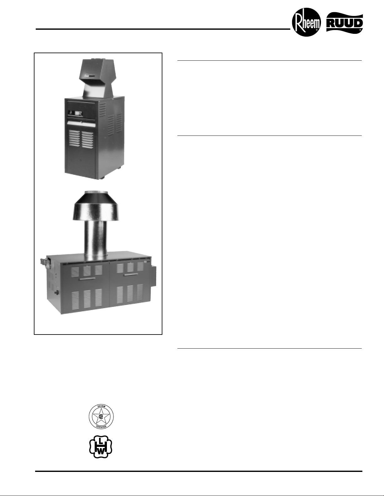
Gas Hot Water Supply Heaters
Available in Indoor and Outdoor Models
136,000 thru 1,826,000 BTU/Hr.
Rheem-Ruud hot water supply heaters are designed to provide hot water service to a variety of commercial applications
when used in conjunction with an appropriately sized storage
tank. These models are particularly suited for applications that
require high inputs and large volumes of stored hot water.
Construction Features:
• Reliable heat exchanger
Design – The all copper
heat exchanger is a single
bank, straight-through
design with a floating
return header immune to
thermal shock.
• Energy saving pump
control – The energy
saving pump control is an
electric device that allows
the operator to set the
desired time for the pump
to run after the water
heater shuts off. With the
energy saving pump control the water heater pump
is programmed to continue running for an optimum
period of time in order to
absorb the residual heat
from the combustion
chamber and use it in the
system.
• Compact design –
The low water heater
mass design offers
substantial savings in
weight and cube over
most cast iron, steel tube
and storage-type water
heaters making it ideal
for rooftop installations
and in tight quarters.
• Minimal heat loss design
– Spark-to-pilot (IID)
system is standard on
all models.
• Glasslined cast iron
headers –
To handle aggressive
water conditions. (Models
GBBP/GBB136 feature
bronze headers.)
Certifications and Ratings:
•
Efficiency – These models have been tested according to ANSI
test procedures, and meet or exceed the 80% thermal efficiency
requirement of current ASHRAE standards (Part of the Federally
mandated Energy Policy Act (EPact)). Also exceeds energy
efficiency codes of all states.
•
Safety and Construction – These products are design certified
by the CSA: a) As a Hot Water Supply Water Heater equipped
with on/off controls for use in conjunction with a storage tank. b)
For operation at 180°F. c) To meet all safety and construction
requirements of ANSI Z21.10.3.c) For installation on combustible
flooring when used with a combustible floor base, and, or e) for
alcove installation. ASME construction is standard on all models.
Certified for a 160 PSI Maximum Working Pressure.
Continued next page.
Indoor and Outdoor
Models
Pump Mounted Models
Available
5 Year Limited Warranty
Indoor Models
Page 2
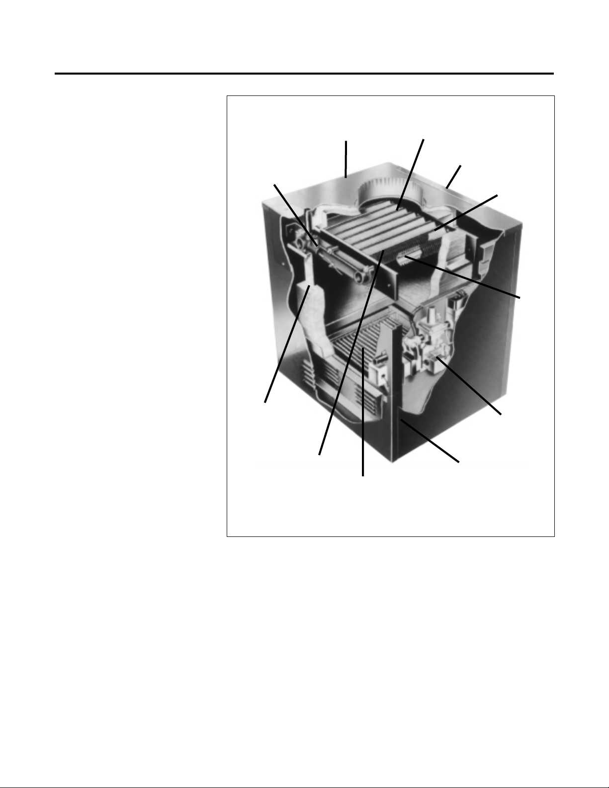
Reliability
• Like all of our water heating products,
Rheem-Ruud hot water supply
heaters are crafted to exacting standards. Each detail of design, engineering and construction must meet
our criteria for performance and durability.
• The heat exchanger (1), for example,
is constructed of 100% copper. High
Velocity hydraulics (2) virtually eliminates problems of scaling and corrosion within its waterways. The cast
iron headers (3) are glass-lined to
assure that the entire heat exchanger
assembly is resistant to corrosion.
• Every Rheem-Ruud hot water supply
heater features titanium stainless
steel burners (4). They operate quietly, will not clog or corrode, and have
far greater temperature resistance
than cast iron. The controls (5) are
factory adjusted and completely
enclosed for reliable, automatic
operation.
• The outer jacket (6) is galvanized
and enamel baked for lasting
aesthetics.
Efficiency
• Today’s demands for volume hot water
must be met economically, so we’ve
attempted to use every fuel saving
technique conceivable. The resulting
82% efficiency will save you money in
fuel costs for years to come.
• The integral finned copper tubing
(7) in the heat exchanger provides
nine times more heat transfer area
than smooth tubing. Efficiency is
boosted even further by V-baffles (8),
which redirect the heat across the
finned tubing. The insulated combus-
tion chamber (9) features corner
sealed and interlocking refractory
panels to minimize chamber radiation
losses.
• Economy is further enhanced with a
special energy saving pump control.
This automatic control continues to
pump operation until all usable heat
has been absorbed from the combustion chamber and stored in the tank.
• Access to water heater for inspection
is simple. All Rheem-Ruud hot water
supply heaters feature a heat
exchanger inspection panel (10)
and a removable door to access the
slide out burner drawer (11).
Flexibility
• You’ll find that Rheem-Ruud hot
water supply heaters are perfectly
suited for many commercial, industrial and special application needs
requiring economical, reliable supplies of hot water. The optional factory supplied pump is designed to
handle nearly all water conditions
• Our standard sized water heaters –
nine models ranging from 136,000 to
825,000 BTU – are designed for hot
water supply in commercial applications. Each model is available for
indoor and outdoor installation. The
outdoor models feature a special
draft system which is wind, rain and
debris-proof.
• Our large sized water heaters –
seven indoor and seven outdoor
models ranging from 926,000 to
1,825,600 BTU – meet the heavier
demand of larger multi-family housing and commercial applications.
They are ideal for use as summer
replacement water heaters, eliminating the need to fire large central
heating water heaters merely to supply domestic hot water.
• All of these Rheem-Ruud hot water
supply heaters are compact and
convenient; they save space, fuel
and installation cost.
1
100% copper
heat exchanger
10
heat exchanger
inspection panel
6
galvanized and
baked enamel jacket
3
cast-iron glasslined headers,
easily removable
8
high efficiency
“V” baffles
7
integral
finned
copper
tubing
5
totally
enclosed
automatic
controls
11
removable door
for access to
slide out
burner drawer
4
precision titanium
stainless steel
burners
2
high velocity
hydraulics
9
corner sealed
and interlocked
combustion
chamber
Three Important Reasons to Choose Hot Water Supply Heaters
from Rheem-Ruud Commercial Water Heaters
Page 3

JACKET INSULATED STORAGE TANKS BY RHEEM-RUUD (All dimensions shown in inches)
Connections Approx. Shipping
Capacity Overall Connection Circulating Relief Valve Weight (Lbs.)
Model Gallons Height Diameter Hot Outlet Line Connection Standard ASME
ST80(A) 80 58-5/16 24-7/16
221
220 260
ST120(A) 115 59-1/4 28-1/4 2 2 1 260 340
ST175(A) 175 67-1/4 32-1/4 2-1/2 2-1/2 1 600 600
ST200A 200 77-1/4 32 2 2-1/2 1 N/A 500
ST260A 257 95-1/2 34 2 3 1-1/4 N/A 1108
ST320A 318 84-1/2 40 2 3 1-1/4 N/A 1290
ST430A 432 84-1/2 46 2 3 1-1/4 N/A 1626
ST500A 504 94-1/2 46 2 3 1-1/4 N/A 1765
ST750A 752 107-1/2 54 2 3 1-1/4 N/A 2330
ST950A 940 131-1/2 54 2 3 1-1/4 N/A 3010
These storage tanks meet standby loss requirements of ASHRAE 90.1b-1992.
(A) ASME code constructed tanks available as an option.
Consult specification sheet for complete details.
RECIRCULATION
PUMP
(BY OTHERS)
RECIRCULATION
DRAIN
OPENING
THERMOMETER
HOT WATER SUPPLY
INDOOR
MODELS
OUTDOOR
MODELS
•• OPTIONAL
INTEGRAL PUMP
ON MODELS 512 - 1826
COLD WATER
A
TANKSTAT
LOCATION
Example System
MINIMUM PIPE SIZE
Model Dimension
Size A
136 1-1/4"
186-399 1-1/2"
512-825 2"
926-1826 2-1/2"
WATER HEATER
SHOWN REPRESENTS VARIOUS
MODELS.
BECAUSE MODELS WILL VARY IN
DRAFT HOOD
DESIGN AND SIZE.
SEE SPECIFIC
WATER HEATER
INFORMATION
FOR DETAILS.
Guaranteed 80% draw without temperature drop,
using Rheem-Ruud water heaters, tanks, sizing tables and hook-up data.
PUMP AND BALL VALVE LOCATION ON
MODELS 136 THRU 399
•• OPTIONAL ON MODELS
512 THRU 1826 WITHOUT INTEGRAL PUMP
PRESSURE
RELIEF VALVE
UNION
BALL VALVE
GATE VALVE
CHECK VALVE
PUMP
KEY
NOTES:
1. PLUMB SWING CHECK VALVE IN GRAVITY CLOSED POSITION.
2. MINIMUM PIPE EQUAL TO WATER HEATER INLET/OUTLET
CONNECTION SIZE BETWEEN WATER HEATER AND TANK(S)
3. PIPE ALL RELIEF VALVES TO DRAIN, OR AS LOCAL CODES
REQUIRE
Page 4

SPECIFICATIONS AND DIMENSIONS
MODEL NUMBER STYLE MBTUH NATURAL GAS (X 1000) DIMENSIONS (INCHES) SHIPPING WEIGHT††
Ref. With- Height Jacket Gas Flue
to out With In- Out- (indoor) (outdoor) Width Overall Height Conn. Dia.
Dwg. Pump Pump door door Input Output Input Output A B C G J K L M N (Indoor) (Outdoor)
1 GBB136* GBBP136* • • 136.0 112.0 136.0 112.0 241⁄8 45.0 301⁄81⁄2 –691⁄4 101⁄4 31⁄2 195 195
GBC186** GBCP186** • • 181.0 148.0 181.0 148.0 18
1
⁄
4 40.0 38
3
⁄
4 12
1
⁄
16 6 – – – 191 200
GBC264** GBCP264** • • 264.0 216.0 264.0 216.0 22
3
⁄8 40.0 38
3
⁄4 111⁄8 7 – – – 214 220
2
GBC331** GBCP331** • • 334.0 274.0 334.0 274.0 25
3
⁄4 40.0 38
3
⁄4 103⁄4 8 – – – 234 240
GBC399** GBCP399** • • 399.0 327.0 399.0 327.0 29
1
⁄
4 40.0 38
3
⁄
4 12
1
⁄
2 9 – – – 253 260
GBC512 GBCP512 • • 511.5 419.4 511.5 419.4 32
3
⁄4 57.0 33 1 – 10 253⁄8 – – 510 535
GBC627 GBCP627 • • 627.0 514.1 627.0 514.1 37
1
⁄2
57.0 33 1 – 12 29
1
⁄2
– – 520 545
3
GBC726 GBCP726 • • 726.0 595.4 726.0 595.4 41
5
⁄8
57.0 33 1 – 12 34
1
⁄4
– – 630 685
GBC825 GBCP825 • • 825.0 676.5 825.0 676.5 45
3
⁄4
57.0 33 1 – 14 38
1
⁄2
– – 660 720
GBC926 GBCP926 – • – – 926.0 759.3 52
3
⁄8
– – 1––––– – 790
GBC962 GBCP962 • – 961.7 788.6 – – 52
3
⁄8
68
3
⁄4
33
1
⁄2
1 18 14 28 – – 760 –
GBC1083 GBCP1083 – • – – 1083.0 888.1 59
1
⁄4
– – 1––––– – 850
GBC1125 GBCP1125 • – 1124.7 922.2 – – 59
1
⁄4
74
1
⁄2
33
1
⁄2
125
5
⁄8
16 32 – – 800 –
GBC1178 GBCP1178 – • – – 1178.0 966.0 63
5
⁄8
– – 1––––– – 910
GBC1223 GBCP1223 • – 1222.5 1002.4 – – 63
5
⁄8
74
1
⁄2
33
1
⁄2
123
5
⁄8
16 32 – – 860 –
GBC1287 GBCP1287 – • – – 1287.0 1055.3 68
5
⁄
8 ––1
1
⁄
4 – – – – – – 975
4
GBC1337 GBCP1337 • – 1336.6 1096.0 – – 68
5
⁄
8 76
1
⁄
2 33
1
⁄
2 1
1
⁄
4 23
5
⁄
8 18 36 – – 930 –
GBC1413 GBCP1413 – • – – 1413.0 1158.7 74
7
⁄8 ––1
1
⁄4 – – – – – – 1065
GBC1467 GBCP1467 • – 1467.0 1202.9 – – 74
7
⁄8 761⁄2 331⁄2 11⁄4 235⁄8 18 36 – – 1000 –
GBC1570 GBCP1570 – • – – 1570.0 1287.4 81
1
⁄
8 ––1
1
⁄
4 – – – – – – 1120
GBC1630 GBCP1630 • – 1630.0 1336.5 – – 81
1
⁄8 791⁄2 361⁄2 11⁄4 235⁄8 18 36 – – 1040 –
GBC1758 GBCP1758 – • – – 1758.0 1441.6 89
3
⁄8 ––1
1
⁄4 – – – – – – 1150
GBC1826 GBCP1826 • – 1825.6 1496.9 – – 89
3
⁄
8 81
1
⁄
2 36
1
⁄
2 1
1
⁄
4 23
5
⁄
8 20 40 – – 1090 –
* Equipped with bronze headers, all other models have glasslined cast iron headers. GBC – cast iron headers. GBB – bronze headers.
†† Subtract 55 lbs. when ordering GBC models.
** Low NOx models add “N” after model number. Outdoor models add “-O” after model number.
Indicate Natural or LP when ordering.
MBTUH PROPANE GAS†
Model
Size Multiplier
136-399 Same as natural gas
512-825 .94
926-1826 .92 Indoor
.955 Outdoor (input)
.92 Outdoor (output)
† Multiplier x Nat. MBTUH = Pro. MBTUH
ELECTRICAL RATINGS
Model
Size With Pump
136-399 3.7 amps @ 120V (1/8 hp pump)
331-399 3.6 amps @ 120V (1/6 hp pump)
512-1826 7.2 amps @ 120V (1/2 hp pump)
MIN. CLEARANCES TO COMBUSTIBLE SURF.
Model Left Right
Top
Size Rear Side Side Indoor Outdoor
136 12" 12" 6" 42" Unobstr.
186-399 12" 12" 12" 39" Unobstr.
512-825 12" 18" 6" 36" Unobstr.
926-1826 24" 24" 24" 24" Unobstr.
For servicing provide 24" minimum unobstructed clearance
in front of unit.
OUTLET
INLET
REAR VIEW
B
L
14
1
/2
10
1
/2
3
1
/4
15
3
/8
7
1
/4
1
1
/4
38
1
/2
24
1
/4
FRONT VIEW
4
7
/8
4
3
/4
C
K
A
G
GAS
ELEC.
CONN.
INDOOR OUTDOOR
UP FRONT
CONTROLS
2
2
OPTIONAL
ON INDOOR
COMBUSTIBLE
FLOOR SHIELD
OUTLET INLET
OUTDOORINDOOR
B
C
28
1
/4
44
1
/8
29
1
/2
11
1
/8
2
1
/4
6
14
3
/4
17
G
GAS
2
K
A
18
14
1
/2
2
1
/4
5
L
A
2
COMBUSTIBLE
FLOOR SHIELD
ELEC
CONN
OPTIONAL
ON INDOOR
K
68-3/4
INDOOR
DRAFT
(B)
STACKLESS
OUTDOOR TOP
PUMP COVER
(OPTIONAL
OUTDOOR
MODELS ONLY)
21-1/4
ELECTRIC
CONNECTION
13-1/4
GAS
CONNECTION
3/4 NPT
GAS
CONNECTION
1-1/2 NPT
WATER
CONNECTION
J
(C)
26-1/2
26-1/2
8-1/2
3-7/8
A
10-1/4
9-7/8
PUMP
(OPTIONAL)
OUTLET
INLET
A
K
B
A
2
18
14
1
/2
11/8
51/8
21/2
273/4
21/2
463/4
321/2
111/4
113/4
111/8
C
J
14
6
G
GAS
5
/8
5
18
OUTDOOR
OPTIONAL
ON INDOOR
OUTLET INLET
COMBUSTIBLE
FLOOR SHIELD
ELEC
CONN
INDOOR
DRAWING 1 DRAWING 2
DRAWING 3 DRAWING 4
Page 5

RECOVERY CAPACITIES
MODEL NUMBER STYLE
INPUT BTU/Hr.
TEMPERATURE RISE – DEGREES F – GALLONS PER HOUR
wo/Pump w/Pump Indoor Outdoor
NATURAL
40° 50° 60° 70° 80° 90° 100° 110° 120° 130° 140°
GBB136 GBBP136 * * 136,000 330 264 220 188 165 147 132 120 110 101 94
GBC186 GBCP186 * * 181,000 440 352 293 251 220 195 176 160 147 135 126
GBC264 GBCP264 * * 264,000 640 512 427 366 320 284 256 233 213 197 183
GBC331 GBCP331 * * 334,000 811 649 541 463 406 360 324 295 270 250 232
GBC399 GBCP399 * * 399,000 967 774 645 553 484 430 387 352 322 298 276
GBC512 GBCP512 * * 511,500 1240 992 827 709 620 551 496 451 413 382 354
GBC627 GBCP627 * * 627,000 1520 1216 1013 869 760 676 608 553 507 468 434
GBC726 GBCP726 * * 726,000 1760 1408 1173 1006 880 782 704 640 587 542 503
GBC825 GBCP825 * * 825,000 2000 1600 1333 1143 1000 889 800 727 667 615 571
GBC926 GBCP926 * 926,000 2245 1796 1497 1283 1122 998 898 816 748 691 641
GBC962 GBCP962 * 961,700 2331 1865 1554 1332 1166 1036 933 848 777 717 665
GBC1083 GBCP1083 * 1,083,000 2625 2100 1750 1500 1313 1167 1050 955 875 808 750
GBC1125 GBCP1125 * 1,124,700 2727 2181 1818 1558 1363 1212 1091 991 909 839 779
GBC1178 GBCP1178 * 1,178,000 2856 2285 1904 1632 1428 1269 1142 1038 952 879 816
GBC1223 GBCP1223 * 1,222,500 2964 2371 1976 1694 1482 1317 1185 1078 988 912 847
GBC1287 GBCP1287 * 1,287,000 3120 2496 2080 1783 1560 1387 1248 1135 1040 960 891
GBC1337 GBCP1337 * 1,336,600 3240 2592 2160 1852 1620 1440 1296 1178 1080 997 926
GBC1413 GBCP1413 * 1,413,000 3425 2740 2284 1957 1713 1522 1370 1246 1142 1054 979
GBC1467 GBCP1467 * 1,467,000 3556 2845 2371 2032 1778 1581 1423 1293 1185 1094 1016
GBC1570 GBCP1570 * 1,570,000 3806 3045 2537 2175 1903 1692 1522 1384 1269 1171 1087
GBC1630 GBCP1630 * 1,630,000 3952 3161 2634 2258 1976 1756 1581 1437 1317 1216 1129
GBC1758 GBCP1758 * 1,758,000 4262 3409 2841 2435 2131 1894 1705 1550 1421 1311 1218
GBC1826 GBCP1826 * 1,825,600 4426 3541 2950 2529 2213 1967 1770 1609 1475 1362 1264
GENERAL FLOW AND PIPING SPECIFICATIONS
Water Hardness
MODELS SOFT MEDIUM HARD
0-4 Grains Per Gallon 5-15 Grains Per Gallon 16 & Over Grains Per Gallon
Indoor Outdoor
T GPMP MPS SHL
T GPMP MPS SHL
T GPMP MPS SHL
136 136 22 10 3.4 1-1/4 5.09 17 13 5.5 1-1/4 8.2 10 22 14.7 1-1/4 22
186 186 15 20 1.82 1-1/2 4.48 11 26 3 1-1/2 7.5 7 40 6.8 1-1/2 17
264 264 21 20 1.85 1-1/2 4.51 16 26 3.1 1-1/2 7.6 10 42 8.3 1-1/2 18.8
331 331 27 20 1.9 1-1/2 4.56 20 26 3.2 1-1/2 7.7 13 42 8.5 1-1/2 19
399 399 30 22 2.1 1-1/2 5.08 25 26 3.3 1-1/2 7.8 15 43 9 1-1/2 19.5
512 512 20 42 1.8 2 4.4 16 52 2.9 2 7 10 84 6.8 2 16.6
627 627 25 41 1.9 2 4.5 19 54 3.1 2 7.2 11 90 8.5 2 20.4
726 726 29 41 2 2 4.6 20 60 4 2 9.3 13 90 9 2 20.8
825 825 30 45 2.5 2 5.7 20 68 5.2 2 11.7 15 90 9.3 2 21.1
962 926 30 53 3.5 2-1/2 4.9 20 79 7.5 2-1/2 10.5 17 90 10.1 2-1/2 14.3
1125 1083 30 61 5.5 2-1/2 7.5 20 90 11.8 2-1/2 16 20 90 11.8 2-1/2 16
1223 1178 30 67 6.5 2-1/2 8.8 22 90 12 2-1/2 16.2 22 90 12 2-1/2 16.2
1337 1287 30 73 8.4 2-1/2 11 24 90 13.3 2-1/2 17.5 24 90 13.3 2-1/2 17.5
1467 1413 30 80 10.8 2-1/2 14.1 26 90 13.8 2-1/2 18 26 90 13.8 2-1/2 18
1630 1570 30 89 13.7 2-1/2 17.6 29 90 14.8 2-1/2 19 29 90 14.8 2-1/2 19
1826 1758 32 90 15.5 2-1/2 19.7 32 90 15.5 2-1/2 19.7 32 90 15.5 2-1/2 19.7
NOTE: Additional pipe fittings will increase the system head loss. Select a pump based on the water hardness, flow and system head loss. If water heater is
more than two stories above the tank, consult the pump manufacturer.
T – Temperature Rise, Degree F @ GPM Flow
GPM – Gallons per Minute Flow
P – Pressure Drop, Ft. thru Heat Exchanger
MPS – Minimum Pipe Size, NPT
SHL – System Head Loss
Sizing based on water heater and tank being placed 5 feet apart. The
equivalent length of pipe valves and fittings in the system is as follows.
1-1/4" NPT = 65 Ft (136)
1-1/2" NPT = 70 Ft (186-399)
2" NPT = 75 Ft (512-825)
2-1/2" NPT = 80 Ft (926-1826)
Page 6

Gas Hot Water Supply Heaters
Heat Exchanger
• Finned Copper Tubes
• ASME Steel Tubesheet
• Silicon O-Rings
• 125 PSIG ASME Pressure Relief Valve
• Glasslined Cast Iron Headers
Controls
• Energy Saving Pump Control
• Flow Switch
• Spark-to-Pilot Ignition System
• High Limit Control
• On/Off Switch
• Flue Gas Spillage Sensor
• Flame Roll-Out Sensor
Gas Control Train
• Manual Gas Shut-Off Cock
• Main Gas Pressure Regulator
• Safety Shut-Off Valve, Redundant
• Control Valve
Construction
• Vent Terminal
• Front Controls Enclosed
• Stainless Steel Burners
• Polytuf Powder Coat Finish
When ordering specify:
■■ wo/Pump (GBC) or ■■ w/Pump (GBCP)
■■ Natural Gas or ■■ L.P.
■■ Indoor or ■■ Outdoor
Hot Water Supply Heater(s) shall be model ________________, manufactured by RHEEM-RUUD,
having gas input of __________ Btu/hr. and recovery rate of _____________ GPH at a 100°F temperature rise when tested and certified at ____________ thermal efficiency. Water heaters(s) shall have the
CSA seal of certification and supplied with a factory installed 125 PSIG ASME pressure relief valve.
Water heater(s) shall meet or exceed the thermal efficiency requirements of ASHRAE. Water heater(s)
shall be ASME inspected and stamped for 160 PSI working pressure complete with manufacturer’s data
report. Water tube heat exchanger shall be constructed of straight integral copper fin tubes with fins
spaced at seven fins per inch. Tube sheets shall be ASME fire box steel. Headers shall be of glasslined
cast iron and joined to the copper tubes and tube sheets by means of silicone “O” rings to form a positive seal between the copper tubes and the headers to 1200 PSI hydrostatic pressure. Headers shall be
secured to the tube sheets by properly spaced bolts and flange nuts. Heat exchanger shall be readily
cleanable from either the right or left sides (or rear) of the water heater by removing header(s), and on
the right side, cleanable without removing external piping. Heat exchanger to be explosion proof on the
water side. Waterways to be 100% copper and glasslined cast iron to prevent galvanic action within the
water heater by positively sealing off water contact between ferrous and non-ferrous metals. Pump, flow
switch, and energy saving pump control are to be factory supplied and units over 400,000 Btu/Hr. must
have electronic intermittent pilot ignition.
Water heater to be equipped with remote bulb electric high limit control adjustable to 200°F. Main
electric gas valve to be 24 volt with 110/24 volt transformer. Gas pressure regulator to be factory set
at 4" W.C. Flame supervision shall be either 60 second thermopilot or 1-4 second electronic shut down.
Burners to be raised port and die formed from stainless steel alloy, mounted on a removable drawer,
capable of quiet ignition and extinction, and equipped with fixed primary air ports.
Models above 330,000 Btu/Hr. shall be CSA design certified for a minimum efficiency of 82% on indoor
and outdoor models.
Limited Warranty
All GB models feature a five year limited warranty on the
copper heat exchanger and glasslined cast iron header.
Please refer to Commercial Warranty Information brochure
for complete limited warranty information.
COMMERCIAL
WATER HEATERS
Rheem Water Heating • 101 Bell Road, Montgomery, Alabama 36117-4305 • www.rheem.com
PRINTED IN U.S.A 10/06 WP FORM NO. RR102C-6 Rev. 11
In keeping with its policy of continuous progress and product improvement, Rheem-Ruud reserves the right to make changes without notice.
Standard Equipment:
Recommended Specifications:
 Loading...