

Page 1

1
INSTALLATION INSTRUCTIONS
SMARTPHONE REMOTE CONTROLLER (Part No. 052310)
This instruction is for installation of Rheem EziSET® with the following Rheem Electronic Continuous Flow Gas water
heater models (refer to the rating plate for model number):
Australia – 876627, 876027, 866627, 866027, 876T26*, 876820*, 876T16* & 876812* Models
(*manufactured since 2018)
New Zealand – 874627, 864627, 874826, 874824, 874820 & 874816 Models
NOTE: Rheem EziSET® must only be installed by a qualified person.
PLEASE NOTE:
1. The Rheem EziSET® module is to be located inside the already-installed Continuous Flow water heater.
2. Rheem EziSET® MUST NOT be used on a Continuous Flow gas water heater installed as a solar booster.
3. Do not install this device when a tempering valve or thermostatic mixing valve is already installed in the hot
water line. The cold water valve inside these valves cannot be fully closed after bath fill function has been
completed, leading to continuous cold water dripping from hot water tap if left open after bath fill.
4. Any installed Rheem wired controllers must be disconnected from the water heater.
5. Should the home electrical power supply be 3-phase, the Rheem EziSET® PLT plug and the water heater MUST
be connected to power outlets supplied by the same phase.
6. Rheem EziSET® communicates between the Continuous Flow water heater and the homeowner’s smartphones
via their home WiFi network connection. No internet or data services are required.
7. The Rheem EziSET® kit includes a PLT plug which has been factory paired. No further set up is required. It
requires an Ethernet socket in the WiFi router and a power outlet. The PLT plug is plugged into a power outlet
adjacent to the home’s WiFi router
8. The Rheem EziSET® smartphone app can be downloaded from App Store or Google Play Store and is
compatible to iOS 8.1 (iPhone 5 or later, excluding iPhone 5C) or Android 4.0 version or later.
The Rheem EziSET® kit contains:
Item
Component Description
Qty
1
Rheem EziSET® module
1
2
Top mounting bracket
1
3
Bottom mounting bracket
1
4
MAC address label
1
5
M4 self tapping screws (required for installation in
some models)
3
6
PLT plug
1
7
Ethernet cable
1
Page 2
2
INSTALLING RHEEM EziSET®
1. Close any hot taps and ensure the
burners are not operating.
2. Turn off the controller(s), if
connected, by pressing the on/off
button. Switch off the
electrical supply at the power outlet
to the water heater and remove the
3 pin plug from the GPO.
3. If remote controllers are NOT
installed, go to Step 7.
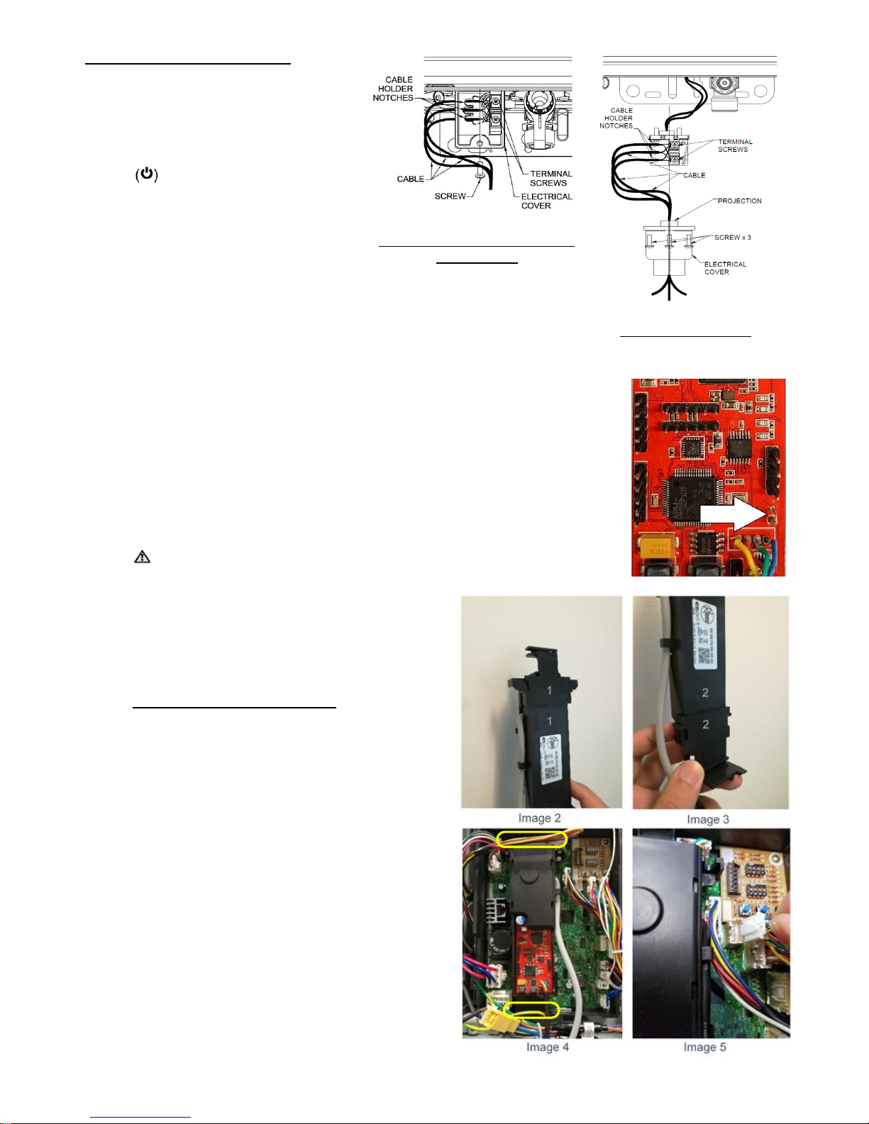
4. Unscrew and open the electrical cover on the underside of the water
heater (refer Diagrams 1 or 2 for respective model).
5. Loosen the terminal screws securing the remote controller cables and
remove the cables.
6. Retighten the terminal screws and secure the electrical cover.
7. For T26, 826, 824, 820, T16, 816 & 812 models only, remove the top and bottom
cover strips to gain access to the front panel screws by pressing on the two ridged
finger points and gently pulling forward.
8. Remove the screws holding the front panel of the jacket.
9. Gently disengage the front panel and remove from the water heater.
Ensure electrical power is turned off (see Step 2 above) as there is
exposed 240V wiring with front panel removed.
NOTE: For New Zealand installations ONLY it is
necessary to cut the resistor wire link indicated in
image 1. This enables setting of the temperature to
55oC in accordance with applicable regulations.
FOR 627 or 027 MODELS ONLY:
10. Assemble Top and Bottom mounting brackets onto
the PCB module housing as shown in images 2 & 3.
Match the markings “1” or “2” stamped on the plastic
parts for the correct fitment.
11. Securely clip the bracket onto the outer edge of the
water heater PCB housing at the location shown in
image 4.
12. Connect the 4-pin plug of the EziSET® module cable
into the socket on the PCB as shown in image 5.
13. Disconnect the yellow power cable connector plug
as shown in image 6 and connect it to the yellow
connectors of the EziSET® module as shown in
image 7.
14. Tuck the power cable away safely to avoid crushing
or damage from the front panel. Go to Step 22.
Image 1
Diagram 1
For T26, 826, 824, 820, T16, 816
& 812 models
Diagram 2
For 627 & 027 models
1
1
Page 3

3
FOR T26, 826, 824, T20, 820, T16, 816 or 812 MODELS:
Note: The Rheem EziSET® module is installed in
these models via 2 screws onto the rear casing of the
water heater as shown in image 8. The Top & Bottom
mounting brackets supplied in the kit are not required.
15. Use an M4 self tapping screw to cut thread in one of
the screw holes on the rear casing, see image 9.
Make 3 turns and leave the screw in place.
16. Repeat Step 15 for the 2nd hole.
17. Insert the EziSET® Module into the space as shown in
image 10.
18. Engage the 2 fixing lugs extending from the sides of
the module onto the screws and fasten both with a
screwdriver, as shown in image 11.
19. Connect the 4-pin plug from the EziSET® module to the
socket on the PCB as shown in image 12.
20. Disconnect the yellow power cable connector shown in
image 13 and connect it with the yellow connectors of
the EziSET® module.
21. Tuck the power cable away safely to avoid crushing
or damage from the front panel.
TESTING WITH PLT PLUG:
22. Plug in the PLT plug to a power outlet adjacent to the
home WiFi router.
23. Connect the Ethernet cable between the PLT plug
and WiFi router. Switch on power to the PLT plug.
Ensure WiFi router is ON and ready.
24. Switch on the power to the water heater. Wait 15
seconds and check for the LED lights below for to
show correct operation.
LEDs on EziSET®
module - image 14
LEDs on PLT
plug - image 15
L2
Green
Ethernet
Green
L3
Blue
Data
Green
L1
Green
Power
Green
L4
Green
L5
Green *
* L5 will be “RED” if the 4-pin plug is not connected to the
water heater PCB. Connect the 4-pin plug, reset power to
the water heater and re-check.
Image 6
Image 7
Image 13
Image 8
Image 12
Image 9
Image 11
Image 10
Page 4

4
25. If homeowner is not home and the home WiFi router
cannot be accessed for Steps 22 & 23, plug the PLT plug
and water heater into a power board. Then observe the
LED lights below to determine correct operation.
# L2 will be “OFF” if the PLT plug is not plugged in or not powered.
* L5 will be “RED” if the 4-pin plug is not connected to the water heater PCB.
Connect the 4-pin plug, reset power to the water heater and re-check.
*** Data light on the PLT plug is “OFF” because Ethernet cable is not connected to WiFi router.
26. Refit the front panel to the water heater.
27. Affix the MAC address label on the underside of the water heater, see image 16.
28. Turn on the cold water and gas isolation valves to the water heater if not already
open.
29. Turn on a hot tap to ensure the water heater operates correctly.
HOMEOWNER INSTALLATION AND CONNECTION OF THE PLT PLUG:
(The following steps can be performed by the Homeowner if installer is unable to gain access to home WiFi router)
30. Plug the PLT plug into a power outlet adjacent to the home WiFi router.
31. Connect the Ethernet cable between the PLT plug and the WiFi router. Switch on the power to the PLT
plug. No configuration or pairing is required. Ensure the WiFi router is ON and ready.
32. Restart the water heater by switching OFF power to water heater. Wait 15 seconds then switch back ON.
Note: Rheem EziSET® is a Plug-n-Play system. It remembers the IP address assigned by the WiFi router so a
secure connection is enabled. Should the WiFi router be replaced or upgraded in the future, Steps 30 to 32
must be performed to re-establish the secure connection with the new router. A new IP address from the router
will be stored in the EziSET module.
RHEEM AUSTRALIA PTY LTD, A.B.N. 21 098 823 511 – for Service Telephone 131 031 AUSTRALIA
RHEEM NEW ZEALAND LTD – for Service Telephone 0800 657 335 NEW ZEALAND
LEDs on EziSET®
module - image 14
LEDs on PLT
plug - image 15
L2
Green #
Ethernet
Green
L3
Blue
Data
OFF ***
L1
Green
Power
Green
L4
Green
L5
Green / Red *
Image 14
Image 15
Image 16
Revision Date: 2018 April
122317A
 Loading...