

Page 1
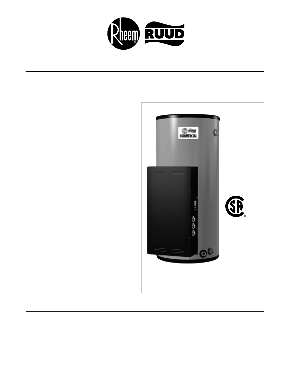
SURFACE MOUNTED ELECTRIC TANK-TYPE
WATER HEATERS 9 KW THRU 36 KW
RHEEM-RUUD line of commercial electric
water heaters come in a broader range of
models. Our completely redesigned single panel
control center with hinged door features ready
access to all controls and elements. With single
or three phase operation, these units provide the
most versatile and dependable operation we’ve
ever offered in a commercial electric water
heater.
Thick, R-Foam
®
insulation completely surrounds
the tank, maximizing heat retention while improving energy costs.
Features the Lifeguard®high-efficiency stainlesssteel clad elements for long element life and
performance.
Seven different inputs from 9 KW to 36 KW to
meet most commercial and industrial needs.
Model Applications
In addition to being suitable for general commercial hot water applications, these units are also
ideal for point-of-use installations, eliminating
costly temperature loss in long piping runs. A
single unit can be used as a booster heater to
satisfy the hot water requirements of commercial
dishwashers. A single temperature storage unit,
when installed with a mixing valve, will supply
two temperatures in food service establishments.
For larger volume hot water requirements, 2, 3 or
4 units can be parallel manifolded, using optional
factory kits.
Energy Information
Rheemglas®commercial electric water heaters are quality engineered to provide the maximum amount of hot
water available from storage capacity of the tank and energy input of heating elements. Surface mounted
thermostat models provide water from 120°F to 160°F (50°C to 71°C). Detailed Engineering Information for
208, 240 and 600 volt models with single or three phase operation will be found in Table A, B or C.
These units have been tested according to procedures specified by CSA and meet or exceed the energy
efficiency requirements of ASHRAE Standard 90.1b 1992 requirements for energy conservation.
50, 85
AND
120 U.S.
GALLON
CAPACITIES
208, 240,
AND 600
VOLTAGES
COMMERCIAL
EGS-SURFACE MOUNTED
THERMOSTAT MODELS
WATER HEATERS
®
Page 2

TANK CAPACITY
50 Gal. (190 L) 85 Gal. (321 L) 120 Gal. (454 L)
EGS50-C-9 EGS85-C-9 EGS120-C-9
EGS50-C-12 EGS85-C-12 EGS120-C-12
EGS50-C-15 EGS85-C-15 EGS120-C-15
EGS50-C-18 EGS85-C-18 EGS120-C-18
EGS50-C-24 EGS85-C-24 EGS120-C-24
EGS50-C-30 EGS85-C-30 EGS120-C-30
EGS50-C-36 EGS85-C-36 EGS120-C-36
INPUT
KW
9
12
15
18
24
30
36
Construction Features
GLASS LINED STORAGE TANK – Heavy
duty steel tank protects with double coating of
exclusive Rheemglas
®
to resist the corrosive
action of hot water. Designed for 150 PSI working
pressure. Each tank is supplied with factory
installed anode rods or cathodic protection.
WATER CONNECTIONS – Hot outlet and
cold inlet are 1-1/2" NPS brass nipples which prevent excessive turbulence of heated water and
result in optimum tank draw.
R-FOAM®INSULATION – A rigid
polyurethane foam insulation provides superior
insulating qualities and improves efficiency.
Exceeds R-16 insulation factor. Our patented
process of injecting R-Foam directly into the insulating cavity adds additional durability and toughness to the heater jacket. Fiberglass insulation
guards against heat loss in the heating element
compartment, and provides easy service access.
SINGLE PANEL CONTROL BOX – With
hinged door, provides immediate access to all
electrical components and elements.
HEATING ELEMENTS – Separate screw-in
type LIFEGUARD
®
elements on 50, 85 and 120
gallon models feature a stainless steel outer
sheath of INCO-LOY
®
800, surrounding a
Nichrome wire filament, to resist water chemical
corrosion and burn-out even in air or sediment…
for long element life and long life performance.
Elements are directly immersed in the water for
efficient transfer of heat, and are easily changed
by simply screwing new ones into the tank.
TERMINAL BLOCK – All models are
equipped with CSA listed terminal blocks for
simplicity of installation. This new terminal block
will accept either copper or aluminum field
connect wire.
ELECTRICAL CONNECTIONS – Pre-wired,
accessible control box with multiple knock-outs on
top and side in size selections to match the
Canadian Electrical Code. Sizes range from 1/2"
to 2". A grounding screw is provided for attaching
an equipment grounding conductor.
AUTOMATIC TEMPERATURE
CONTROL – Temperature is maintained by a
surface mounted thermostat adjustable to provide
water 120°F to 160°F (50°C to 71°C) that insure
instant shut off at the selected temperature for
safety and economy of operation. Over temperature protection is provided by surface mounted
high temperature limit controls, one per heating
element, factory set at 190°F (88°C).
STANDARD EQUIPMENT ASME T&P
RELIEF VALVE – This is a double safety valve
that relieves when temperature or pressure
becomes excessive.
MODEL NUMBERS
Page 3

TABLE A – ELECTRICAL CHARACTERISTICS
INPUTKWNO. OF
ELEMENTS
ELEMENT
WATTAGE
FULL LOAD CURRENT
IN AMPERES
208 VOLTS
PHASE
1 3
240 VOLTS
PHASE
1 3
600 VOLTS
PHASE
1 3
9 3 3000 43 25 38 22 – 9
12 3 4000 58 33 50 29 – 12
15 3 5000 72 42 63 36 – 15
18 3 6000 87 50 75 43 – 18
24 6 4000 116 67 100 58 – 23
30 6 5000 144 84 125 73 – 29
36 6 6000 173 100 150 87 – 35
TABLE B – RECOVERY CAPACITIES
Recovery in U.S. Gallons/Hr. (GPH) and Liters/Hr. (LPH) at Various Temperature Rises
INPUT EQUIVALENT 40°F 50°F 60°F 70°F 80°F 90°F 100°F 110°F 120°F 130°F 140°F
KW BTU/HR. UNITS (22°C) (28°C) (33°C) (39°C) (45°C) (50°C) (56°C) (61°C) (67°C) (72°C) (78°C)
9 30,709 GPH 93 74 62 53 47 41 37 34 31 29 27
LPH 352 282 235 201 176 157 141 128 117 108 101
12 40,946 GPH 124 99 83 71 62 55 50 45 41 38 35
LPH 470 376 313 268 235 209 188 171 157 145 134
15 51,183 GPH 155 124 103 89 78 69 62 56 52 48 44
LPH 587 470 391 335 294 261 235 213 196 181 168
18 61,420 GPH 186 149 124 106 93 83 74 68 62 57 53
LPH 705 564 470 403 352 313 282 256 235 217 201
24 81,893 GPH 248 199 165 142 124 110 99 90 83 76 71
LPH 939 751 626 537 470 417 376 342 313 289 268
30 102,366 GPH 310 248 207 177 155 138 124 113 103 95 89
LPH 1174 939 783 671 587 522 470 427 391 361 335
36 122,839 GPH 372 298 248 213 186 165 149 135 124 115 106
LPH 1409 1127 939 805 705 626 564 512 470 434 403
SAMPLE SPECIFICATIONS (For Trade Reference Only)
Water Heater shall be Rheemglas Commercial Electric Model _____________ having an input of ________KW
and a recovery rate of ______________GPH at a __________° temperature rise, and equipped for ________ volt,
________ phase operation. Tank shall be lined with a double coating of exclusive Rheemglas high temperature
glass formula and furnished with rigidly supported anode rods. Tank shall be designed for 150 PSI working pressure and be approved-listed and constructed in accordance with Canadian Electrical Codes. Tank shall be completely insulated with R-Foam
®
Insulation having a minimum insulation factor of R-16. Water heater shall be
equipped with
”screw-in” immersion elements, surface thermostat, and manual reset high temperature limit control. Large
terminal block that accepts either CU or AL field connect wire, plus grounding screw for attaching an equipment grounding
conductor.
LIMITED WARRANTY
This product features a three year limited warranty against tank leaks. Please refer to Commercial Warranty
Information brochure for complete warranty information.
Page 4

Rheem Manufacturing Company • Water Heater Division
Rheem Canada Ltd./Ltée,128 Barton Street West, Hamilton, Ontario L8N 3P3
Customer Service 1-800-268-6966
Warranty 1-800-263-8342
FORM NO. RR102CE-5CAN Rev. 2 03/05 WP
In keeping with its policy of continuous progress and product improvement, Rheem-Ruud reserves the right to make changes without notice.
EST. 1947
RHEEM
CANADA
LTD/LTÉE
THANKS TO OUR EMPLOYEES
WE ARE
ISO9002
REGISTERED
COMMERCIAL
WATER HEATERS
TABLE C – DIMENSIONAL INFORMATION
All dimensions shown in English and Metric
MODEL APPROX. SHIPPING
NUMBER ABCDE WEIGHT
50 GALS.
inches 43-5/8 26-1/4 36-1/4 32 17-1/4 270 lbs.
mm 1108 667 920 813 438 122 kgs.
85 GALS.
inches 57-11/16 28-1/4 49-1/2 34 18-1/4 350 lbs.
mm 1465 718 1258 864 464 159 kgs.
120 GALS.
inches 67-5/8 30-1/4 58-3/4 36 19-1/4 430 lbs.
mm 1718 768 1493 914 489 185 kgs.
B
D
E
A
43/4"
(121mm)
361/
8
"
(917mm)
3
/4"
T&P
5"
(127mm)
SYSTEM SENTINEL
THERMOSTATS,
ENERGY CUT-OFFS,
HEATING ELEMENTS
& GASKETS (3, 6 OR 9
11/2"
COLD INLET
NIPPLE
1
1
/2"
HOT OUTLET
NIPPLE
C
SYSTEM SENTINEL – All models
employ a diagnostic panel utilizing light
emitting diodes (L.E.D.), corresponding
to the number and location of each
heating element. L.E.D.’s are energized
when the electric elements are operating. An unlit L.E.D. pinpoints the exact
location of a non-functioning element,
making element operation diagnosis
simple and positive.
The minimum distance to provide
adequate clearance for protection of
combustible material is 0 inches from
jacket and 18 inches from access
door. However, additional clearance for
accessibility to permit inspection and
servicing such as removing heating
elements or checking controls must be
provided. All models are approved for
installation on combustible flooring.
 Loading...