

Page 1
Heavy Duty Electric
Commercial Water Heaters
Available in 50, 85 and 120 Gallon Tank-Type Models
6 KW thru 81 KW
Rheem-Ruud Electric Commercial Water Heaters are suitable for general commercial
hot water applications and are also ideal for point-of-use installations. A single unit can
be used as a booster heater to satisfy the hot water requirements of commercial dishwashers. A single temperature storage unit, when installed with a mixing valve, will
supply two temperatures in food service establishments.
Construction Features:
• System Sentinel –
immersion thermostat models employ
an element diagnostic panel, utilizing
light emitting diodes (L.E.D.), corresponding to the number and location
of each heating element. This system
monitors the on-off function of the
electric heating elements.
• Long life ASME tank design –
proprietary steel formulation with
high temperature porcelain enamel to
maximize corrosion resistance resulting in a superior tank design.
• LIFEGUARD heating elements –
separate screw-in type elements feature a stainless steel outer sheath of
INCO-LOY 840, surrounding a
Nichrome wire filament, to resist water
chemical corrosion and burn-out even
in air or sediment…for long element
life and long life performance.
Elements are directly immersed in the
water for maximum recovery efficiency
(98%) and are easily changed by simply screwing new ones into the tank.
LIFEGU
ARD elements feature a three
(3) year limited warranty.
• Full port, full flow brass drain
valve
• Minimal heat loss design –
85% of the tank surface area on all
Rheem-Ruud Commercial Electric
products are insulated with 3" of rigid
polyurethane foam insulation providing
superior insulating qualities. Unlike
other designs, Rheem-Ruud
Commercial Electrics can achieve 85%
because of the unique compact layout
of the heating elements. This results
in heat losses less than the energy
used by a 100 watt light bulb during
a 48 hour standby period!
Certifications and Ratings:
• Efficiency –
in accordance with ANSI test procedures, these models tested
below the maximum allowable standby loss levels of ASHRAE Standard
90.1b-2001 (Part of the Federally mandated Energy Policy Act (EPact)).
Also exceeds energy efficiency codes of all states including California Energy
Commission (CEC).
• Safety and construction –
These products are design certified by Underwriters
Laboratories (UL) to meet UL standard 1453 as electric booster and commercial
storage tank water heaters. All models are North Carolina code compliant.
CERTIFIED FOR A
150 PSI MAXIMUM WORKING PRESSURE
(160 PSI FOR ASME MODELS).
• Optional construction –
ASME construction is available on immersion
thermostat models.
Continued on reverse.
208, 240,
277 and 480
Voltages
Surface Mounted
and Immersioin
Thermostat
Models
(With Optional
Seal Kit)
®
Page 2
Heavy Duty Electric continued.
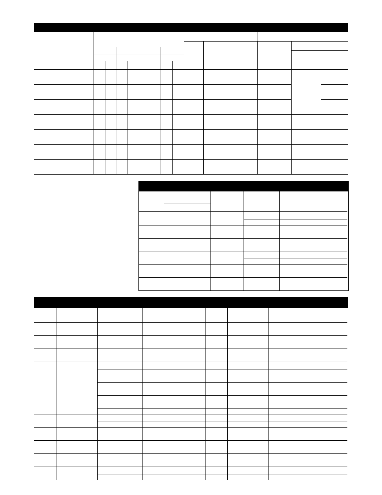
RECOVERY CAPACITIES Recovery in U.S. Gallons/Hr. (GPH) and Liters/Hr. (LPH) at Various Temperature Rises
INPUT EQUIVALENT 40°F 50°F 60°F 70°F 80°F 90°F 100°F 110°F 120°F 130°F 140°F
KW BTU/HR. UNITS (22°C) (28°C) (33°C) (39°C) (45°C) (50°C) (56°C) (61°C) (67°C) (72°C) (78°C)
6 20,473 GPH 62 50 41 35 31 28 25 23 21 19 18
LPH 235 188 157 134 117 104 94 85 78 72 67
9 30,709 GPH 93 74 62 53 47 41 37 34 31 29 27
LPH 352 282 235 201 176 157 141 128 117 108 101
12 40,946 GPH 124 99 83 71 62 55 50 45 41 38 35
LPH 470 376 313 268 235 209 188 171 157 145 134
15 51,183 GPH 155 124 103 89 78 69 62 56 52 48 44
LPH 587 470 391 335 294 261 235 213 196 181 168
18 61,420 GPH 186 149 124 106 93 83 74 68 62 57 53
LPH 705 564 470 403 352 313 282 256 235 217 201
24 81,893 GPH 248 199 165 142 124 110 99 90 83 76 71
LPH 939 751 626 537 470 417 376 342 313 289 268
27 92,129 GPH 279 223 186 160 140 124 112 102 93 86 80
LPH 1057 845 705 604 528 470 423 384 352 325 302
30 102,366 GPH 310 248 207 177 155 138 124 113 103 95 89
LPH 1174 939 783 671 587 522 470 427 391 361 335
36 122,839 GPH 372 298 248 213 186 165 149 135 124 115 106
LPH 1409 1127 939 805 705 626 564 512 470 434 403
45 153,549 GPH 465 372 310 266 233 207 186 169 155 143 133
LPH 1761 1409 1174 1006 881 783 705 640 587 542 503
54 184,259 GPH 558 447 372 319 279 248 223 203 186 172 160
LPH 2114 1691 1409 1208 1057 939 845 769 705 650 604
81 276,388 GPH 838 670 558 479 419 372 335 305 279 258 239
LPH 3174 2540 2116 1814 1587 1410 1270 1154 1058 977 907
INPUT
KW
NO.
OF
ELE-
MENTS
ELE-
MENT
WAT-
TAG E
FULL LOAD CURRENT
IN AMPERES
208V
Phase
1 3
240V
Phase
1 3
277V
Phase
1
480V
Phase
1 3
IMMERSION THERMOSTATS
Number
of
Contactors
Number
of
Fuses
Staged T’Stats
No. of
T’Stats
KW Step
Size
Thermostat Staging –
On all immersion thermostat
models, 24kW and above
(18kW for 208V), additional
thermostats can be provided
so that the maximum element
input will not exceed 18kW 27 kW per step. Temperature
differential between steps can
be set as desired.
Note: Thermostat staging
recommended on 81kW models.
No.
of
T’Stats
Number
of
Fuses
SURFACE MOUNTED
WATER TEMPERATURE RATINGS
Minimum Maximum High
Model
Tank Capacity
Thermostat Delivered Delivered Temperature
Number Gallons Liters Type Temperature Temperature Limit
ES50 50 189 Surface 90°F 160°F 180°F
32.2°C 71.1°C 82.2°C
ES85 85 322 Surface 120°F 160°F 190°F
48.8°C 71.1°C 87.8°C
ES120 119.9 454 Surface 120°F 160°F 190°F
48.8°C 71.1°C 87.8°C
E50 50 189 Immersion 90°F 190°F 200°F
32.2°C 87.8°C 93.3°C
E85 85 322 Immersion 90°F 190°F 200°F
32.2°C 87.8°C 93.3°C
E120 119.9 454 Immersion 90°F 190°F 200°F
32.2°C 87.8°C 93.3°C
N/A
ONE
T’STAT
STD.
6 3 2000 29 17 25 14 22 13 7 1 6 2 6 16
9 3 3000 43 25 38 22 33 19 11 1 6 2 6 19
12 3 4000 58 33 50 29 43 25 15 1 6 2 6 12
15 3 5000 72 42 63 36 54 31 18 1 6 2 6 15
18 3 6000 – – 75 43 65 38 22 1 6 2 6 18
18 6 3000 87 50 – – – – – 1 12 4 12 2 19
24 6 4000 116 67 100 58 87 50 29 1 12 4 12 2 12
27 6 4500 130 75 113 65 98 56 33 1 12 4 12 2 13.5
30 6 5000 144 84 125 73 108 63 36 1 12 4 12 2 15
36 6 6000 – – 150 87 130 75 43 1 12 4 12 2 18
36 9 4000 173 100 – – – – – 1 18 6 18 3 12
45 9 5000 217 125 188 109 163 94 54 1 18 6 18 3 15
54 9 6000 260 150 225 130 195 113 65 1 18 6 18 3 18
81 9 9000 – – – – – 169 98 – – – 18 3 27
ELECTRICAL CHARACTERISTICS
Page 3

• Fuse type –
the “G” in the model number represents Class G fuses.
• Thermostat staging –
E models (Immersion thermostat) 24 kW and above (18 kW for 208V), may be ordered
with additional thermostat(s) for staging. Add “S” after fuse type designation. Recommended on 81kW models.
Example: E85-36-G becomes E85-36-GS.
• ASME construction –
E models (Immersion Thermostat) may be ordered with ASME certified construction.
Add “A” after capacity designation. Example: E85-36-G becomes E85A-36-G.
• UL Sanitation compliance –
all models are UL Sanitation (NSF5) compliant when equipped with the optional
ring seal kits. E(S)50 – AS38355, E(S)85 – AS38356, E(S)120 – AS38357.
• Solid state low water cut-off –
E models (Immersion Thermostat) may be ordered with probe type cut-off for
field installation (AP8408).
SURFACE MOUNTED THERMOSTATS IMMERSION THERMOSTATS
Tank Capacity In Gallons Tank Capacity In Gallons
50 85 120 50 85 120
ES50-6-G ES85-6-G ES120-6-G E50-6-G E85-6-G E120-6-G
ES50-9-G ES85-9-G ES120-9-G E50-9-G E85-9-G E120-9-G
ES50-12-G ES85-12-G ES120-12-G E50-12-G E85-12-G E120-12-G
ES50-15-G ES85-15-G ES120-15-G E50-15-G E85-15-G E120-15-G
ES50-18-G ES85-18-G ES120-18-G E50-18-G E85-18-G E120-18-G
ES50-24-G ES85-24-G ES120-24-G E50-24-G E85-24-G E120-24-G
ES50-27-G ES85-27-G ES120-27-G E50-27-G E85-27-G E120-27-G
ES50-30-G ES85-30-G ES120-30-G E50-30-G E85-30-G E120-30-G
ES50-36-G ES85-36-G ES120-36-G E50-36-G E85-36-G E120-36-G
ES50-45-G ES85-45-G ES120-45-G E50-45-G E85-45-G E120-45-G
ES50-54-G ES85-54-G ES120-54-G E50-54-G E85-54-G E120-54-G
N/A N/A N/A N/A E85A-81-GS E120A-81-GS
INPUT
KW
6
9
12
15
18
24
27
30
36
45
54
81
DIMENSIONAL INFORMATION All dimensions shown in English and Metric
MODEL
APPROX. SHIPPING
WEIGHT (LBS.)
NUMBER UNITS
ABCDE
STD. ASME
E(S)50 inches 43-5/8 26-1/4 36-1/4 32 17-1/4 270 lbs. 320 lbs.
mm 1108 667 920 813 438 122 kgs. 145 kgs.
E(S)85 inches 57-11/16 28-1/4 49-1/2 34 18-1/4 350 lbs. 380 lbs.
mm 1465 718 1258 864 464 159 kgs. 172 kgs.
E(S)120 inches 67-5/8 30-1/4 58-3/4 36 19-1/4 430 lbs. 460 lbs.
mm 1718 768 1493 914 489 185 kgs. 209 kgs.
B
D
E
A
43/4"
(121mm)
361/
8
"
(917mm)
T&P
5"
(127mm)
SYSTEM SENTINEL
AUTOMATIC
TEMPERATURE
CONTROL
(IMMERSION ONLY)
11/2"
COLD INLET
NIPPLE
1
1
/2"
HOT OUTLET
NIPPLE
C
• System Sentinel –
all models employ a diagnostic panel
utilizing light emitting diodes (L.E.D.),
corresponding to the number and
location of each heating element.
L.E.D.’s are energized when the electric elements are operating. An unlit
L.E.D. pinpoints the exact location of
a non-functioning element, making
element operation diagnosis simple
and positive.
The minimum distance to provide
adequate clearance for protection of
combustible material is 0 inches from
jacket and 18 inches from access door.
However, additional clearance for
accessibility to permit inspection and
servicing such as removing heating
elements or checking controls must be
provided. All models are approved for
installation on combustible flooring.
Heavy Duty Electric continued.
MODEL NUMBERS
Page 4

Water heater(s) shall be model ________________, manufactured by RHEEM-RUUD, having electrical input of __________
kW and a recovery rate of _____________ GPH at a 100°F temperature rise. Water heater(s) shall have a storage capacity of
___________ gallons. Water heater(s) shall have the UL seal of certification and be factory equipped with an AGA/ASME rated
temperature and pressure relief valve. Tank(s) shall have a double coating of high temperature porcelain enamel and furnished
with magnesium anode rods rigidly supported. Water heater(s) shall meet or exceed the standby loss requirements of
ASHRAE Standard 90.1b-2001. Tank(s) shall have a working pressure of 150 psi, and shall be completely assembled. Water
heater(s) shall be approved-listed and constructed in accordance with UL Sanitation (NSF5). Water heater(s) shall be equipped
with LIFEGUARD “screw-in” type elements featuring a stainless steel outer sheath of INCO-LOY 840 material. Tank shall be
insulated with 3" of rigid polyurethane foam insulation. Water heater(s) shall be constructed with a SYSTEM SENTINEL
element diagnostic panel utilizing light emitting diodes. Each LED will correspond to the number and location of the heating
elements and monitor their on-off function. Water heater(s) shall be provided with internal power circuit fusing, control circuit
fusing, magnetic contactors, 120 volt control circuit transformer and surface mounted thermostat or immersion thermostat(s)
with manual reset high limit control. 1-1/2" inlet and outlet water connections shall be provided. Water heater(s) shall be
covered by a three year limited warranty against tank leaks.
Add for ASME construction
Water heater(s) shall be constructed in accordance with the requirements of the ASME Boiler and Pressure Vessel Code,
Section IV Part HLW.
This product features a three year limited warranty against tank leaks. Please refer to Commercial Warranty Information
brochure for complete warranty information.
Recommended Specifications:
Limited Warranty:
COMMERCIAL
WATER HEATERS
Rheem Water Heating • 101 Bell Road, Montgomery, Alabama 36117-4305 • www.rheem.com
Rheem Canada Ltd./Ltée,128 Barton Street West, Hamilton, Ontario L8N 3P3
PRINTED IN U.S.A 02/06 WP FORM NO. RR102CE-1 Rev. 12
In keeping with its policy of continuous progress and product improvement, Rheem-Ruud reserves the right to make changes without notice.
Heavy Duty Electric continued.
Other Features:
• Integral Fusing –
all models have integral fusing for each element.
• Anode Rods –
two (2) magnesium anodes are installed in each tank
to ensure long life and corrosion resistance.
• Temperature and Pressure Relief Valve –
AGA/ASME rated and factory installed.
• Electrical Connections –
pre-wired, accessible control box with multiple knockouts on side in size selections to match the National
Electric Code. Sizes range from 1/2" to 2". A grounding screw is provided for attaching an equipment
grounding conductor.
• Single Panel Control Box –
with hinged door, provides immediate access to all
electrical components and elements.
• Terminal Block –
all models are equipped with U.L. listed terminal
blocks for simplicity of installation. The terminal
block will accept either copper or aluminum field
connect wire.
• 120 Volt Control Circuit –
all units are furnished with a fused 120 volt control
circuit. All controls (thermostats, high temperature
limit, etc.) are operated off of this basic 120 volt
control circuit. This circuit is created by an internal
multi-tap transformer of unique design that has four
(4) taps for the primary voltages, 208, 240, 277
and 480.
• Water Connections –
hot outlet and cold inlet are 1-1/2" NPT dielectric
nipples which prevent excessive turbulence of heated
water and results in optimum tank draw.
 Loading...