

Page 1
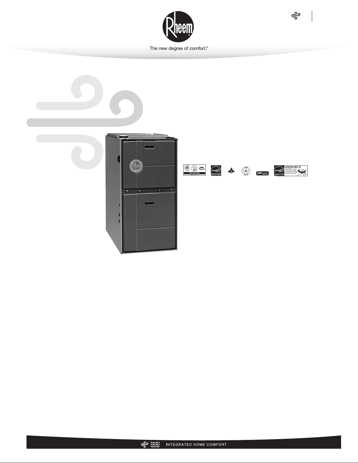
Rheem Classic®Series Two-Stage
Upflow Gas Furnaces
FORM NO. G11-523
RGRM- Series
45K through 105K Models Rated at 95% A.F.U.E.†,
120K Model Rated at 93.3% A.F.U.E.†
Input Rates of 45, 60, 75, 90, 105 & 120 kBTU
[13.19-35.17 kW]
With Dual Comfort Control
™
“The RGRM- 12 gas furnace has earned the ENERGY STAR®in all
U.S. South States.”
✝A.F.U.E. (Annual Fuel Utilization Efficiency) calculated in
accordance with Department of Energy test procedures.
• The Rheem Classic®Series 95% A.F.U.E. with Dual Comfort
Control
™
line of upflow gas furnaces are designed for utility
rooms, closets, alcoves, or attics. Because of the low-profile
34 inch [864 mm] height, the upflow model can also be used
to satisfy most applications. The design is certified by CSA.
• Two stages of operation to save energy and maintain optimal
comfort level.
• Furnace operates at 70% capacity for low-heat and 100%
capacity for high-heat.
• Compatible with single or two-stage thermostat. (For optimal
performance a two-stage thermostat is recommended.)
• Heat exchanger is constructed aluminized steel for maximum
corrosion resistance and thermal fatigue reliability.
• Low profile “34 inch” design is lighter and easier to handle
and leaves room for optional accessories.
• Left or right side gas, electric, and condensate drainage
connections.
• Integrated control board manages all operational functions
and provides hookups for humidifier and electronic air cleaner.
• An insulated blower compartment, a slow-opening gas valve
and a specially designed inducer system make it one of the
quietest furnaces on the market today.
• Variable speed blower motor technology provides ultimate
humidity control, quieter sound levels and year-round energy
savings.
• Optional indoor or outdoor combustion air. In addition, combustion air may be piped to either the top or side of the cabinet on all upflow models. A special molded fitting is provided
to ease installation.
• Solid bottom is standard.
• Control board diagnostics.
• A variety of cooling coils and plenums designed to use with
the Rheem Classic
®
Series 95% A.F.U.E. gas furnaces are
available as optional accessories for air conditioning models.
Air
Gas Furnaces
RGRM Series
Page 2

Air
Table of Contents
RGRM Series
2
TABLE OF CONTENTS
Standard & Optional Equipment ......................................................................3
Physical Data & Specifications ........................................................................4
Model Number Identification ............................................................................5
Dimensional Data............................................................................................6
Blower Performance Data ................................................................................7
Accessories....................................................................................................8
Limited Warranty ............................................................................................9
Page 3
Air
Standard & Optional Equipment
RGRM Series
3
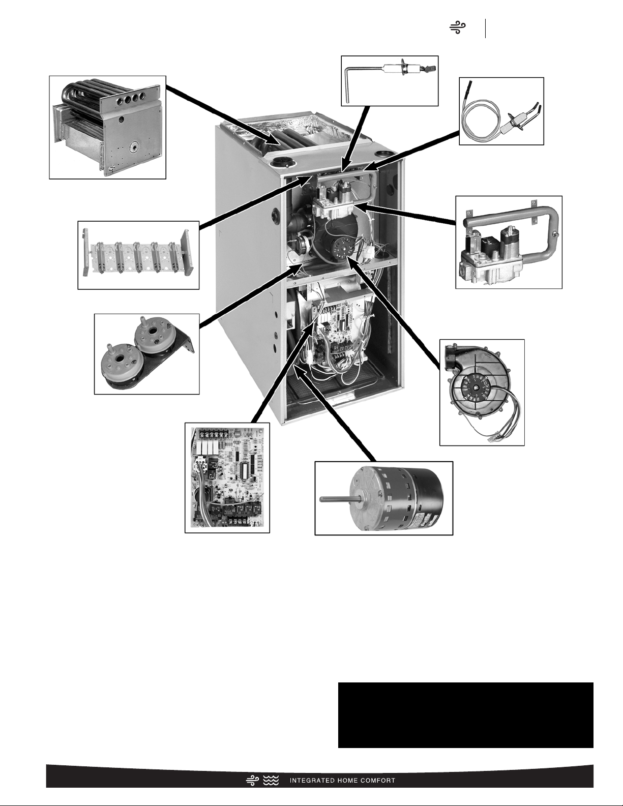
STANDARD EQUIPMENT
Completely assembled and wired; heat exchanger; primary
aluminized steel, secondary: 29-4C stainless steel; induced
draft; pressure switches; redundant main gas control; blower
compartment door safety switch; solid state time on/off
blower control; limit controls; manual shut-off valve; 100%
safety lock out; cool fan off delay; field selectable heat fan off
delay; one hour automatic retry; power and self-test
diagnostics; flame sense current diagnostics; electronic air
cleaner connections; humidifier connections; humidifier on/off
delay; low speed continuous fan option; single speed option
for heating and cooling applications; pressure regulator for
natural and L.P. (propane) gasses; transformer; direct drive,
multi-speed blower motor. (Please note: a thermostat is not
included as standard equipment.)
WARNING
THIS FURNACE IS NOT APPROVED
OR RECOMMENDED
FOR USE IN MOBILE HOMES
PRIMARY AND SECONDARY
HEAT EXCHANGER
REMOTE
SENSOR
IN-SHOT BURNERS
PRESSURE SWITCHES
DRAFT INDUCER
INTEGRATED
FURNACE
CONTROL
GAS VALVE AND
MANIFOLD
DIRECT SPARK IGNITION &
REMOTE SENSOR
ECM MOTOR
OPTIONAL EQUIPMENT
Side and bottom filter racks; return air cabinet for all sizes.
NOTE: Furnace is not listed for use with fuels other than
natural or L.P. (propane) gas.
All models can be converted by a qualified distributor or local
service dealer to use L.P. (propane) gas without changing
burners. Factory approved kits must
be used to convert from natural to L.P. (propane) gas and may
be ordered as optional accessories from a parts distributor.
For L.P. (propane) operation, refer to Conversion Kit Index Form.
Page 4
Air
Physical Data & Specifications
RGRM Series
4
Physical Data and Specifications—Upflow Models
U.S. and Canadian Models
MODEL NUMBERS RGRM-04*MAES RGRM-06*MAES RGRM-09*ZAJS**
HIGH FIRE INPUT BTU/HR [kW] ➀
45,000 [13.19] 60,000 [17.58] 90,000 [26.38]
LOW FIRE INPUT BTU/HR [kW] ➁
31,500 [9.23] 42,000 [12.31] 63,000 [18.46]
HIGH ALTITUDE INPUT 8000' ➁
30,600 [8.97] 40,800 [11.96] 61,200 [17.94]
HIGH ALTITUDE OUTPUT
AT 8000' (HIGH FIRE) [kW] ➁
28,458 [8.34] 37,944 [11.12] 56,916 [16.69]
BLOWER (D x W)
[mm]
11 x 7
[279 x 178]
11 x 7
[279 x 178]
12 x 11**
[305 x 279]
MOTOR H.P. [W]–
SPEEDS–TYPE
1
/2 [373] VAR.
SPEED
1
/2 [373] VAR.
SPEED
1 [746] VAR.
SPEED
MOTOR FULL LOAD AMPS 8.7 8.7 12
MINIMUM EXT. STATIC
PRESSURE (IN. W.C.) [kPa]
.10 [0.25] .12 [.029] .15 [.037]
LOW HEATING CFM @ .2"
[.049 kPa] W.C. E.S.P. [L/s]
850 725 1275
HIGH HEATING CFM @ .2"
[.049 kPa] W.C. E.S.P. [L/s]
780 900 1450
HIGH COOLING CFM @ .8"
[.124 kPa] W.C. E.S.P. [L/s]
A = 1200 A = 1200
A = 2000/900
C = 800 C = 800 C = 1400
TEMPERATURE RISE-HIGH FIRE
RANGE IN DEGREES °F [°C]
30-60
[16.7-33.3]
40-70
[22.2-38.9]
35-65
[19.4-36.1]
APPROX. SHIPPING WEIGHT
(LBS.) [kg]
117
[53.2]
123
[56.0]
148
[67.3]
AFUE ➂
95.0% 95.0% 95.0%
RETURN AIR CABINETS (OPT.)
RXGRFILTER SIZE
[mm]
C17B
(2) 12" x 16"
[305 x 406]
C17B
(2) 12" x 16"
[305 x 406]
C21B
(2) 12" x 20"
[305 x 508]
STANDARD, HIGH VELOCITY
PERMANENT FILTER (IN.)
153/4 x 25 x 1 153/4 x 25 x 1 191/4 x 25 x 1
HEATING CAPACITY BTU/HR [kW] 42,000 [12.31] 56,000 [16.41] 84,000 [24.62]
TEMPERATURE RISE-LOW FIRE
RANGE IN DEGREES °F [°C]
15-45
[8.3-25]
35-65
[19.4-36.1]
25-55
[13.9-30.6]
MAXIMUM EXT. STATIC
PRESSURE (IN. W.C.) [kPa]
.80 [0.2] .80 [0.2] .80 [0.2]
RGRM-07*MAES
153/4 x 25 x 1
75,000 [21.98]
52,500 [15.39]
51,000 [14.95]
70,000 [20.51]
47,430 [13.90]
11 x 7
[279 x 178]
1
/2 [373] VAR.
SPEED
35-65
[19.4-36.1]
8.7
.12 [.029]
.80 [0.2]
765
1080
A = 1200
C = 800
40-70
[22.2-38.9]
128
[58.2]
95.0%
C17B
(2) 12" x 16"
[305 x 406]
RGRM-07*YBGS
153/4 x 25 x 1
75,000 [21.98]
52,500 [15.39]
51,000 [14.95]
70,000 [20.51]
47,430 [13.90]
12 x 7
[305 x 178]
1 [746] VAR.
SPEED
20-50
[11.1-27.8]
12
.12 [.029]
.80 [0.2]
1180
1180
A = 1600
C = 1200
35-65
[19.4-36.1]
139
[63.2]
95.0%
C21B
(2) 12" x 20"
[305 x 508]
RGRM-10*ZAJS**
105,000 [30.77]
191/4 x 25 x 1
73,500 [21.54]
71,400 [20.93]
66,402 [19.46]
97,000 [28.43]
12 x 11**
[305 x 279]
1 [746] VAR.
SPEED
12
30-60
[16.7-33.3]
.20 [.049]
1400
.80 [0.2]
1604
A = 2000/800
C = 1400
40-70
[22.2-38.9]
150
[68.2]
95.0%
C21B
(2) 12" x 20"
[305 x 508]
RGRM-12*RAJS
120,000 [35.17]
223/4 x 25 x 1
84,000 [24.62]
81,600 [23.91]
75,888 [22.24]
113,000 [33.12]
11 x 10
[279 x 254]
1 [746] VAR.
SPEED
12
40-70
[22.2 – 38.9]
.20 [.049]
1250
.80 [0.2]
1450
A = 2000
C = 1400
50-80
[27.8-4.4]
159
[72.3]
93.3%
C24B
(2) 14" x 16"
[609 x 406]
B = 1000 B = 1400 B = 1600B = 1000 B = 1000 B = 1600 B = 1600
D = 600 D = 1000 D = 1200D = 600 D = 600 D = 1200 D = 1200
A = 900
C = 600
A = 1200
C = 900
A = 1500
LOW COOLING CFM @ .8"
[.124 kPa] W.C. E.S.P. [L/s]
A = 900 A = 900
C = 1050
A = 1500
C = 600 C = 600 C = 1050
A = 1500
C = 1050
B = 750 B = 1050 B = 1200B = 750 B = 750 B = 1200 B = 1200
D = 450 D = 750 D = 900D = 450 D = 450 D = 900 D = 900
180MAX. OUTLET AIR TEMPERATURE 160 170 170 165 180 180
NOTES: All models are 115V, 60HZ, 1 phase. Gas connection size for all models is 1/2" [13 mm] N.P.T.
➀ See Conversion Kit Index Form for high altitude derate.
➁ Canadian installations only.
➂ In accordance with D.O.E. test procedures.
*E=Standard
*N=NOx Models
**12 x 11 Housing, 11 x 10 Wheel
[ ] Designates Metric Conversions
WARNING: Some heating airflow values may be higher
than those required for cooling. Be sure to size duct
systems for highest possible airflow value.
Page 5

Air
Model Number Identification
RGRM Series
5
Model Number Identification
R G R M 07E* BY G S
Rheem Gas
Furnace
Upflow
Condensing
Gas Furnace
Design
Series
Heating Input
Designation
Variations
A = Std.
B = Wide
Blower Size
M = 11 x 7
[279 x 178 mm]
R = 11 x 10
[279 x 254 mm]
Z = 12 x 11**
[305 x 279 mm]
Y = 12 x 7
[305 x 178 mm]
Heat/Cool
Designation
E = 1100-1300 CFM
[519-613.5 L/s]
G = 1500-1700 CFM
[707.9-802.3 L/s]
J = 1900-2100 CFM
[896.7-991.1 L/s]
Fuel Code
S = U.S. and
Canadian
Electric
Ignition
04
*
06
*
07
*
09
*
10*
12*
Input
BTU/HR
45,000 [13.19 kW]
60,000 [17.58 kW]
75,000 [22 kW]
90,000 [26.38 kW]
105,000 [30.77 kW]
120,000 [35.17 kW]
278**
Option Code
for
High Altitude
—
Available Models:
RGRM-04EMAES RGRM-07EMAES RGRM-09EZAJS278**
RGRM-04NMAES RGRM-07NMAES RGRM-10EZAJS**
RGRM-04EMAES278 RGRM-07EYBGS RGRM-10NZAJS**
RGRM-06EMAES RGRM-07NYBGS RGRM-12ERAJS
RGRM-06NMAES RGRM-09EZAJS** RGRM-12NRAJS
RGRM-06EMAES278 RGRM-09NZAJS** RGRM-12ERAJS78
[ ] Designates Metric Conversions
NOTES: *E = Standard
*N = NO
x
Models
**12 x 11 Housing, 11 x 10 Wheel
Page 6

Air
Dimensional Data
RGRM Series
6
*
E=Standard
*
N=NO
x
[ ] Designates Metric Conversions
MODEL
RGRM-
A B C D E F
LEFT
SIDE
MINIMUM CLEARANCE (IN.) [mm]
RIGHT
SIDE
BACK TOP FRONT VENT
04*M 17.5 [445] 1611/32 [415] 155/8 [397] 2 [51] 151/2 [422] 1325/32 [352] 0 0 0 1 [25] 2 [51] 0
06*M 17.5 [445] 1611/32 [415] 155/8 [397] 2 [51] 151/2 [422] 1325/32 [352] 0 0 0 1 [25] 2 [51] 0
07*M 17.5 [445] 1611/32 [415] 155/8 [397] 2 [51] 151/2 [422] 1325/32 [352] 0 0 0 1 [25] 2 [51] 0
07*Y 21 [533] 1927/32 [504] 191/8 [487] 2 [51] 181/2 [511] 179/322 [441] 0 0 0 1 [25] 2 [51] 0
09*Z 21 [533] 1927/32 [504] 191/8 [487] 2 [51] 181/2 [511] 179/322 [441] 0 0 0 1 [25] 2 [51] 0
10*Z 21 [533] 1927/32 [504] 191/8 [487] 2 [51] 181/2 [511] 179/322 [441] 0 0 0 1 [25] 2 [51] 0
12*R 24.5 [622]
2311/32 [593] 225/8 [575]
2 [51]
221/2 [600] 2025/32 [530]
0 0 0 1 [25] 2 [51] 0
Page 7

Air
Blower Performance Data
RGRM Series
7
MODEL
RGRM-
BLOWER
SIZE (D x W)
IN. [mm]
ECM
MOTOR
H.P. [W]
BLOWER
SPEED
CFM [L/s] AIR DELIVERY
EXTERNAL STATIC PRESSURE
INCHES WATER COLUMN [kPa]
RGRM-07*M
11 x 7
[279 x 178]
1/2
[373]
HIGH
MED-HI
MED
LOW
1200 [566]
1000 [472]
800 [378]
600 [283]
0.1 [.02] – 0.8 [.20]
RGRM-04*M
11 x 7
[279 x 178]
1/2
[373]
HIGH
MED-HI
MED
LOW
1200 [566]
1000 [472]
800 [378]
600 [283]
RGRM-06*M
11 x 7
[279 x 178]
1/2
[373]
HIGH
MED-HI
MED
LOW
1200 [566]
1000 [472]
800 [378]
600 [283]
RGRM-09*Z**
12 x 11**
[305 x 279]
1
[746]
HIGH
MED-HI
MED
LOW
1900 [887]
1600 [755]
1400 [661]
1200 [566]
RGRM-07*Y
12 x 7
[305 x 279]
1
[746]
HIGH
MED-HI
MED
LOW
1600 [755]
1400 [661]
1200 [566]
1000 [472]
RGRM-10*Z**
12 x 11**
[305 x 279]
1
[746]
HIGH
MED-HI
MED
LOW
1800 [850]
1600 [755]
1400 [661]
1200 [566]
RGRM-12*R
11x 10
[279 x 254]
1
[746]
HIGH
MED-HI
MED
LOW
2000 [944]
1600 [755]
1400 [661]
1200 [566]
*E=Standard
*N=NO
x Models
NOTE: CFM values represent furnace-only airflow ratings.
**12 x 11 Housing, 11 x 10 Wheel
[ ] Designates Metric Conversions
Page 8

Air
Accessories
RGRM Series
8
VENT TERMINATION KITS CONCENTRIC:
HORIZONTAL/VERTICAL =
RXGY-E03A (US & Canadian Installations)
HORIZONTAL TWO PIPE: RXGY-D02, RXGY-D03, RXGY-D04
(US Installations)
RXGY-D02A, RXGY-D03A, RXGY-D04A (Canadian Installations)
RXGY-G02 (US Only)
CONDENSATE PUMP KIT: RXGY-B01
NEUTRALIZER KIT: RXGY-A01
FOSSIL FUEL KIT: RXPF-F01, RXPF-F02 (TVA)
RETURN AIR PLENUM: RXGR-C17B, RXGR-C21B, RXGR-C24B
FILTER RACK FILTER SIZES* INCHES [mm]
MODEL
RGRM-
RXGF-CB
(BOTTOM)
04
153/4 x 25
[400 x 635]
09
191/4 x 25
[489 x 635]
10
191/4 x 25
[489 x 635]
12
223/4 x 25
[578 x 635]
RXGF-CA
(SIDE)
153/4 x 25
[400 x 635]
153/4 x 25
[400 x 635]
153/4 x 25
[400 x 635]
153/4 x 25
[400 x 635]
07EM
07NM
153/4 x 25
[400 x 635]
153/4 x 25
[400 x 635]
06
153/4
x 25
[400 x 635]
153/4
x 25
[400 x 635]
07EY
07NY
191/4 x 25
[489 x 635]
153/4 x 25
[400 x 635]
*Filter racks are shipped without filters.
Filters shipped with furnace may be used or a suitable 1" [25.4 mm] filter.
[ ] Designates Metric Conversions
Option – 278 furnaces are shipped with #51 DMS orifices installed.
This is one drill size smaller than standard furnaces to account for
expected average elevations and heating values typically seen in
these areas.
CAUTION: Always follow National Fuel Gas Code (NFGC) guidelines
when converting for high altitudes.
For all installations above 2000 ft. (including all option – 278 models),
the burner orifice size needs to be recalculated and verified. A burner
orifice change may still be required. See Installation Instructions for
more information.
NOTE: For Canadian installations only, an optional derate (manifold
gas pressure reduction) method may be used to adjust the
furnace for altitude. See Installation Instructions for more
information. This optional method may NOT be used for U.S.
installations.
(U.S. Models—Kit packaged with furnace.
Requires field installation).
LP CONVERSION KITS:
U.S./Canadian RXGJ-FP26 or RXGJ-FP21
EXTERNAL BOTTOM FILTER RACK: RXGF-CB
EXTERNAL SIDE FILTER RACK: RXGF-CA
FOR HIGH ALTITUDES:
HIGH ALTITUDE KIT:
PLENUM DATA FOR “A” COILS
Plenum adapters are required in some instances for use on upflow
applications when plenum and furnace size do not match.
Note: See Form Number C11-206 for MultiFlex®coil data.
FURNACE
WIDTH
IN. [mm]
141/
2 [356]
141/2 [356] 201/4 [514] RXAA-C172 RXAL-B20BU
171/2 [445] 161/4 [413] RXAA-C185 RXAL-B16BU
171/
2 [445]
171/2 [445] 215/8 [549]
171/2 [445] 251/4 [641]
21 [533] 251/
21 [533] 221/4 [565]
21 [533] 215/8 [549] RXAA-C188 RXAL-B21BU
241/
2 [622]
241/2 [622] 215/8 [549] RXAA-C187 RXAL-B21BU
PLENUM
WIDTH
IN. [mm]
161/
4 [413]
201/
4 [514]
4 [641]
251/
4 [641]
PLENUM ADAPTER
UPFLOW
RXAA-C171 RXAL-B16BU
RXAA-C173 RXAL-B20BU
RXAA-C187 RXAL-B21BU
RXAA-C174 RXAL-B25BU
RXAA-C175 RXAL-B25BU
RXAA-C176 RXAL-B22BU
RXAA-C177 RXAL-B25BU
PLENUM
COIL
INPUT BTU/HR [kW] HIGH ALTITUDE KIT NO.
RGRM-04*M RXGY-F18
RGRM-06*M
RGRM-07*M Not Required
RGRM-07*Y Not Required
RGRM-09*Z RXGY-F20
RGRM-10*Z Not Required
RGRM-12*R RXGY-F21
RXGY-F18
Page 9

Air
Limited Warranty
RGRM Series
9
GENERAL TERMS OF LIMITED WARRANTY*
Rheem will furnish a replacement for any part of this product
which fails in normal use and service within the applicable
period stated, in accordance with the terms of the limited
warranty.
*For complete details of the Limited and Conditional Warranties, including
applicable terms and conditions, contact your local contractor or the
Manufacturer for a copy of the product warranty certificate.
Conditional Unit Replacement
(Registration Required)...............................Ten (10) Years
Conditional Parts
(Registration Required)...............................Ten (10) Years
Heat Exchanger .........................................Limited Lifetime
Page 10

Air
Notes
RGRM Series
10
Page 11

Air
Notes
RGRM Series
11
Page 12

The new degree of comfort.
™
Rheem Heating, Cooling & Water Heating • P.O. Box 17010
Fort Smith, Arkansas 72917 • www.rheem.com
In keeping with its policy of continuous progress and product improvement, Rheem reserves the right to make changes without notice.
PRINTED IN U.S.A 05/12 QG FORM NO. G11-523
Rheem Canada Ltd./Ltée • 125 Edgeware Road, Unit 1
Brampton, Ontario • L6Y 0P5
 Loading...