

Rheem CF2414STAMCA, CF2417SEAMCA, CF2417STAMCA, CF2417MTAMCA, CF2421MEAMCA Installation Manual
...Page 1
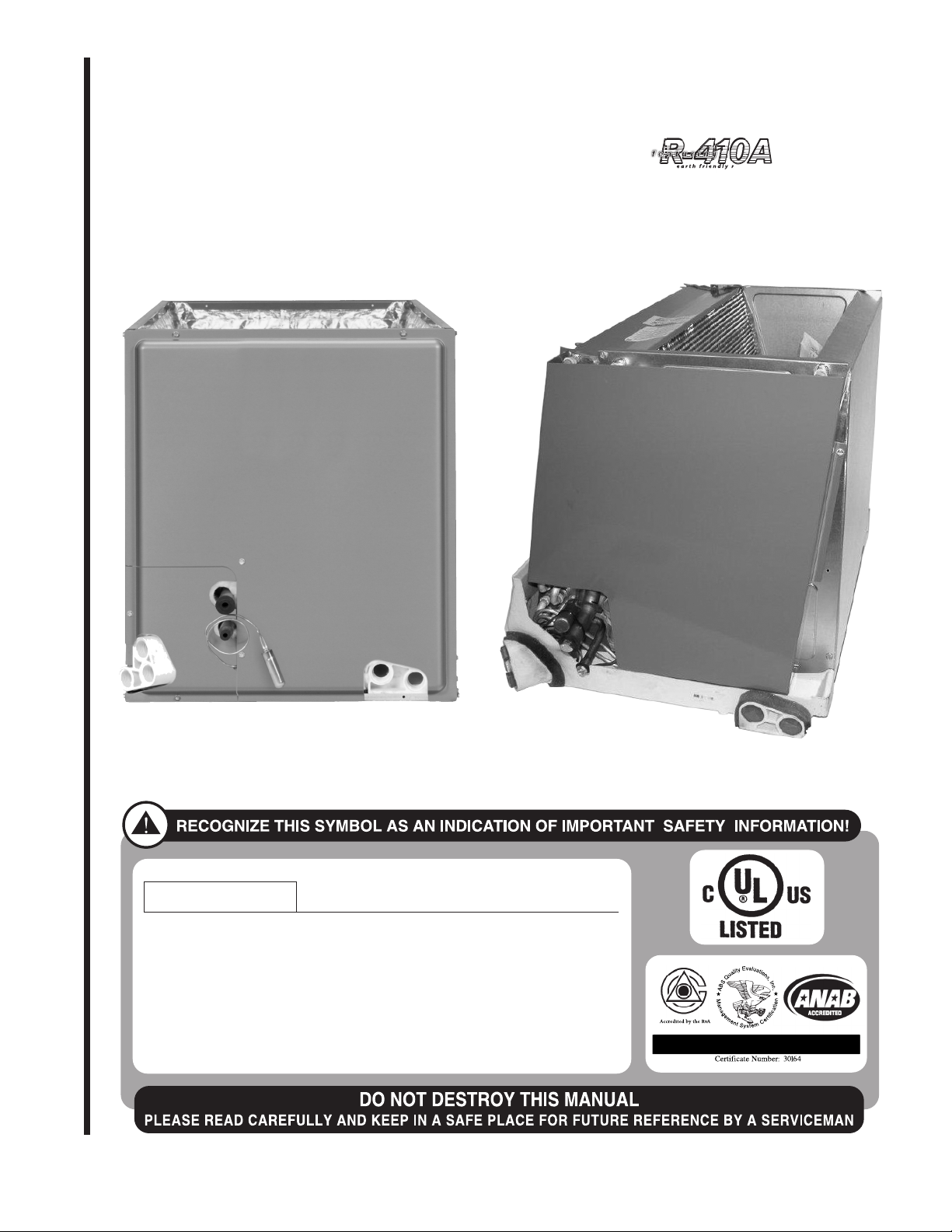
INSTALLATION INSTRUCTIONS
WARNING
ISO 9001:2008
FOR CASED/UNCASED COILS FOR GAS FURNACES:
(-)CF: featuring Industry-Standard R-410A
(-)CF: Refrigerant
!
▲WARNING
These instructions are intended as an aid to qualified licensed
service personnel for proper installation, adjustment and
operation of this unit. Read these instructions thoroughly before
attempting installation or operation. Failure to follow these
instructions may result in improper installation, adjustment,
service or maintenance possibly resulting in fire, electrical
shock, property damage, personal injury or death.
SUPERSEDES 92-100105-13-10
92-100105-13-11
Page 2

TABLE OF CONTENTS
1.0 Safety Information . . . . . . . . . . . . . . . . . . . . . . . . . . . . . . . . . . . . . . . . . . . . . . . . . .3
2.0 General Information . . . . . . . . . . . . . . . . . . . . . . . . . . . . . . . . . . . . . . . . . . . . . . . . .4
.1 Inspection . . . . . . . . . . . . . . . . . . . . . . . . . . . . . . . . . . . . . . . . . . . . . . . . . . . .4
2
2.2 Codes & Regulations . . . . . . . . . . . . . . . . . . . . . . . . . . . . . . . . . . . . . . . . . . .4
2.3 Replacement Parts . . . . . . . . . . . . . . . . . . . . . . . . . . . . . . . . . . . . . . . . . . . . .5
2.4 Model Number Explanation . . . . . . . . . . . . . . . . . . . . . . . . . . . . . . . . . . . . . . .5
2.5 Coil Specifications . . . . . . . . . . . . . . . . . . . . . . . . . . . . . . . . . . . . . . . . . . . . . .6
2.5A Coil Specifications: Dimensions & Weights . . . . . . . . . . . . . . . . . . . . . .6
2.5B Coil Specifications: Airflow Pressure Drop . . . . . . . . . . . . . . . . . . . . . . .7
3.0 Installation . . . . . . . . . . . . . . . . . . . . . . . . . . . . . . . . . . . . . . . . . . . . . . . . . . . . . . . .8
3.1 Applications . . . . . . . . . . . . . . . . . . . . . . . . . . . . . . . . . . . . . . . . . . . . . . . . . . .8
3.2 Refrigerant Connections . . . . . . . . . . . . . . . . . . . . . . . . . . . . . . . . . . . . . . . .10
3.3 TEV Sensing Bulb . . . . . . . . . . . . . . . . . . . . . . . . . . . . . . . . . . . . . . . . . . . . .10
3.4 Electronic Expansion . . . . . . . . . . . . . . . . . . . . . . . . . . . . . . . . . . . . . . . . . .10
3.5 EXV Vapor Line Thermister . . . . . . . . . . . . . . . . . . . . . . . . . . . . . . . . . . . . .10
3.6 Factory Programmed Superheat . . . . . . . . . . . . . . . . . . . . . . . . . . . . . . . . . .12
3.7 Superheat Offset Dip Switch Settings . . . . . . . . . . . . . . . . . . . . . . . . . . . . . .12
3.8 EXV Step Dip Switches . . . . . . . . . . . . . . . . . . . . . . . . . . . . . . . . . . . . . . . .12
3.9 Diagnostics . . . . . . . . . . . . . . . . . . . . . . . . . . . . . . . . . . . . . . . . . . . . . . . . . .12
3.10 EXV Standalone Control Physical Interface . . . . . . . . . . . . . . . . . . . . . . . . .13
3.11 EXV Standalone Control Optional Mounting Locations . . . . . . . . . . . . . . . .13
3.12 EXV Standalone Wiring . . . . . . . . . . . . . . . . . . . . . . . . . . . . . . . . . . . . . . . .14
3.13 Flow Check Piston . . . . . . . . . . . . . . . . . . . . . . . . . . . . . . . . . . . . . . . . . . . .15
3.14 Condensate Drain Tubing . . . . . . . . . . . . . . . . . . . . . . . . . . . . . . . . . . . . . . .16
3.15 Duct Flanges . . . . . . . . . . . . . . . . . . . . . . . . . . . . . . . . . . . . . . . . . . . . . . . . .17
3.16 Coil End Shields . . . . . . . . . . . . . . . . . . . . . . . . . . . . . . . . . . . . . . . . . . . . . .17
4.0 Maintenance . . . . . . . . . . . . . . . . . . . . . . . . . . . . . . . . . . . . . . . . . . . . . . . . . . . . . .17
4.1 Air Filter . . . . . . . . . . . . . . . . . . . . . . . . . . . . . . . . . . . . . . . . . . . . . . . . . . . . . .17
4.2 Indoor Coil - Drain Pan - Drain Line . . . . . . . . . . . . . . . . . . . . . . . . . . . . . . . .17
5.0 Accessories . . . . . . . . . . . . . . . . . . . . . . . . . . . . . . . . . . . . . . . . . . . . . . . . . . . . . .18
5.1 Plenum Adapter Accessory . . . . . . . . . . . . . . . . . . . . . . . . . . . . . . . . . . . . . . .18
5.2 Horizontal Adapter Kit . . . . . . . . . . . . . . . . . . . . . . . . . . . . . . . . . . . . . . . . . . .19
5.3 RXBC- Indoor Coil Casing . . . . . . . . . . . . . . . . . . . . . . . . . . . . . . . . . . . . . . . .19
5.4 Uncased Coil Adapter Kit . . . . . . . . . . . . . . . . . . . . . . . . . . . . . . . . . . . . . . . . .20
5.5 TXV Conversion Kits . . . . . . . . . . . . . . . . . . . . . . . . . . . . . . . . . . . . . . . . . . . .21
2
Page 3
1.0 SAFETY INFORMATION
WARNING
!
These instructions are intended as an aid to qualified licensed service personnel for proper installation, adjustment and operation of this unit. Read these
instructions thoroughly before attempting installation or operation. Failure to
ollow these instructions may result in improper installation, adjustment, serv-
f
ice or maintenance possibly resulting in fire, electrical shock, property damage, personal injury or death.
WARNING
!
PROPOSITION 65: This appliance contains fiberglass insulation. Respirable
particles of fiberglass are known to the State of California to cause cancer.
All manufacturer products meet current Federal OSHA Guidelines for safety.
California Proposition 65 warnings are required for certain products, which are
not covered by the OSHA standards.
California's Proposition 65 requires warnings for products sold in California
that contain or produce any of over 600 listed chemicals known to the State of
California to cause cancer or birth defects such as fiberglass insulation, lead in
brass, and combustion products from natural gas.
All “new equipment” shipped for sale in California will have labels stating that
the product contains and/or produces Proposition 65 chemicals. Although we
have not changed our processes, having the same label on all our products
facilitates manufacturing and shipping. We cannot always know “when, or if”
products will be sold in the California market.
You may receive inquiries from customers about chemicals found in, or produced by, some of our heating and air-conditioning equipment, or found in natural gas used with some of our products. Listed below are those chemicals
and substances commonly associated with similar equipment in our industry
and other manufacturers.
• Glass Wool (Fiberglass) Insulation
• Carbon Monoxide (CO).
• Formaldehyde
• Benzene
More details are available at the websites for OSHA (Occupational Safety and
Health Administration), at www.osha.gov
(Office of Environmental Health Hazard Assessment), at www.oehha.org
Consumer education is important since the chemicals and substances on the
list are found in our daily lives. Most consumers are aware that products present safety and health risks, when improperly used, handled and maintained.
and the State of California’s OEHHA
.
CAUTION
For horizontal applications, the horizontal drain pan must be located under the
indoor coil. Failure to place the pan under the coil can result in property damage.
CAUTION
It is recommended that an auxiliary/secondary drain pan be installed under units
containing evaporator coils that are located in any area of a structure where
damage to the building or building contents may occur as a result of an overflow
of the coil drain pan or a stoppage in the primary condensate drain piping.
3
Page 4

2.0. GENERAL INFORMATION
2.1. INSPECTION
Immediately upon receipt, all cartons, and contents should be inspected for transit dam-
ge. Units with damaged cartons should be opened immediately. If damage is found, it
a
should be noted on the delivery papers and a damage claim filed with the last carrier.
Shipping damage is not covered by the warranty.
• After unit has been delivered to job site, remove carton taking care not to damage
unit.
• Check the unit rating plate to be sure equipment matches what is required for the job
specification.
• Read the entire instructions before starting the installation. This is particularly important if this is the first installation for this specific model series.
• Many installation steps done prior to installing the unit can save time and simplify the
installation.
2.2. CODES/REGULATIONS
Units should be installed in accordance with any local or national codes which may
apply. Latest editions are available from: “National Fire Protection Association, Inc.,
Batterymarch Park, Quincy, MA 02269.”
These publications are:
• ANSI/NFPA Latest Edition (NEC) National Electrical
Code.
• NFPA90A Installation of Air conditioning and
Ventilating Systems.
• NFPA90B Installation of Warm Air Heating and Air
Condition ing Systems.
2.3. REPLACEMENT PARTS
Any replacement part must be the same as or an approved alternate to the original part
supplied. The manufacturer will not be responsible for replacement parts not designed to
physically fit or operate within the design parameters the original parts were selected for.
When ordering replacement parts, it is necessary to order by part number and include
the complete model number and serial number from the coil rating plate. (See parts list
for unit component part numbers. Parts are available through the local distributor.)
4
Page 5
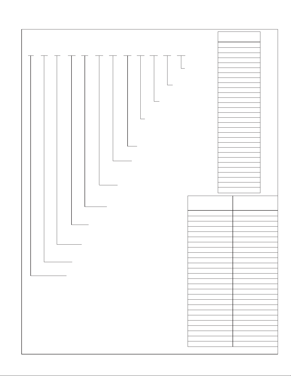
2.4 MODEL NUMBER EXPLANATION
IGURE 1
F
ODEL NUMBER EXPLANATION
M
(-) CF24 17 ST AMUC*
MINOR
SERIES**
CASING
C - CASED
U - UNCASED
ORIENTATION
M - MULTIPOSITION
V - VERTICAL ONLY/
V - CONVERTIBLE**
H - DED. HORIZONTAL ONLY
MAJOR SERIES
A - 1ST DESIGN
METERING DEVICE
T - TXV
E - EEV
P - PISTON
EFFICIENCY
S - STANDARD EFF.
M - MID EFF.
H - HIGH EFF.
WIDTH
14 - 14” 21 - 21”
17 - 17.5” 24 - 24.5”
CAPACITY
24 - 2 TON 48 - 4 TON
36 - 3 TON 60 - 5 TON
TYPE
F - FURN COIL
PRODUCT CATEGORY
C - EVAP COIL
BRAND
TRADEBRAND
**CONVERTIBLE TO HORIZONTAL USING PARTS FROM ORIGINAL
COIL OR USING RXHH KIT.
PTION
O
ODE
C
*TBD
A - 1ST
DESIGN
AVAILABLE UNCASED
REPLACEMENT ORIGINAL
(-)CF2414STAVUA (-)CFL-??2414??
(-)CF2417STAVUA (-)CFL-??2417??
(-)CF2417MTAVUA (-)CFL-??2617??
(-)CF2421MTAVUA (-)CFL-??2621??
(-)CF3617STAVUA (-)CFL-??3617??
(-)CF3621STAVUA (-)CFL-??3621??
(-)CF3621MTAVUA (-)CFL-??3821??
(-)CF3624MTAVUA (-)CFL-??3824??
(-)CF4821STAVUA (-)CFL-??4821??
(-)CF4824STAVUA (-)CFL-??4824??
(-)CF6024STAVUA (-)CFL-??6024??
(-)CF2417HTAVUA (-)CFN-??2417??
(-)CF2421HTAVUA (-)CFN-??2421??
(-)CF3624HTAVUA (-)CFN-??3624??
(-)CF4824HTAVUA (-)CFN-??4824??
(-)CF6024HTAVUA (-)CFN-??6024??
(-)CF2417SPAVUA (-)CFP-??2417??
(-)CF3617SPAVUA (-)CFP-??3617??
(-)CF3621SPAVUA (-)CFP-??3621??
(-)CF4821SPAVUA (-)CFP-??4821??
(-)CF4824SPAVUA (-)CFP-??4824??
(-)CF2417SEAVUA —
(-)CF2421MEAVUA —
(-)CF3621MEAVUA —
(-)CF6021SEAVUA —
(-)CF6024MEAVUA —
?? = ANY LETTER
AVAILABLE CASED
COILS
(-)CF2414STAMCA
(-)CF2417SEAMCA
(-)CF2417STAMCA
(-)CF2417MTAMCA
(-)CF2421MEAMCA
(-)CF2421MTAMCA
(-)CF3617SEAMCA
(-)CF3617STAMCA
(-)CF3621HTAMCA
(-)CF3621MEAMCA
(-)CF3621STAMCA
(-)CF3621MTAMCA
(-)CF3624MTAMCA
(-)CF4821MTAMCA
(-)CF4821STAMCA
(-)CF4824STAMCA
(-)CF6024STAMCA
(-)CF2417HTAMCA
(-)CF2421HTAMCA
(-)CF3624HTAMCA
(-)CF4824HTAMCA
(-)CF6021STAMCA
(-)CF6021SEAMCA
(-)CF6024HTAMCA
(-)CF6024MEAMCA
(-)CF2417SPAMCA
(-)CF3617SPAMCA
(-)CF3621SPAMCA
(-)CF4821SPAMCA
(-)CF4824SPAMCA
COILS COILS
5
Page 6
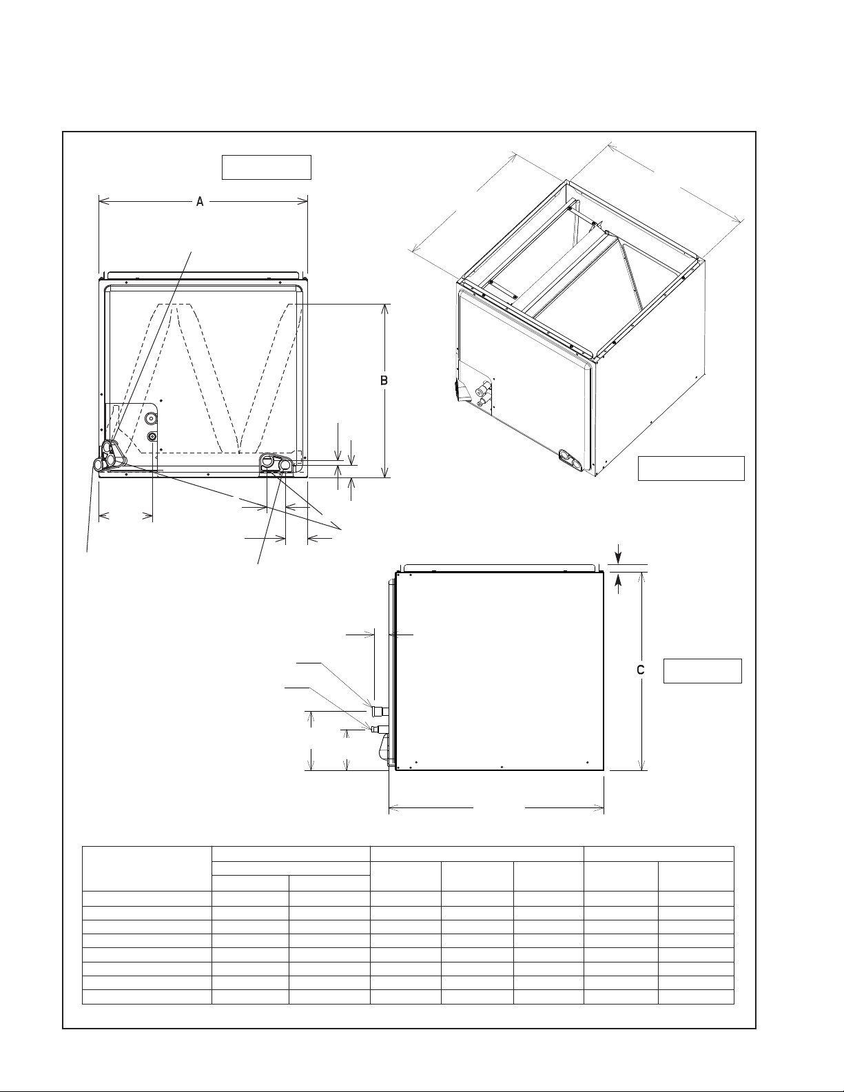
2.5 COIL SPECIFICATIONS
2.5A Coil Specifications: Dimensions & Weights (See Figure 2)
FIGURE 2
DIMENSIONS & WEIGHTS
SECONDARY DRAIN
3/4" N.P.T. (HORIZONTAL)
FRONT VIEW
7
/16”
[11.1 mm]
7
9
1
/8”
505 mm]
[
A MINUS ONE INCH ➀
53/8”
[136.5
mm]
PRIMARY DRAIN
3/4" N.P.T. (VERTICAL
AND HORIZONTAL)
113/16”
[46 mm]
21/4”
[57.1 mm]
PRIMARY DRAIN
3/4" N.P.T. (VERTICAL)
[36.5 mm]
11/4”
[31.7 mm]
SECONDARY DRAIN
3/4" N.P.T. (VERTICAL)
17/16”
SUCTION LINE
LIQUID LINE
515/16”
[150.8 mm]
41/8”
[104.7 mm]
➀ CASING TOP AND BOTTOM OPENINGS
ARE THE SAME DIMENSIONS.
DIMENSIONS AND WEIGHTS DATA
Coil
Model
2414S* 3/8 [9.53] 3/4 [19.05] 14 [356] 20
2417S 3/8 [9.53] 3/4 [19.05] 17
2417M 3617S 2417H 3/8 [9.53] 3/4 [19.05] 17
2421M 3621S 2417H 3/8 [9.53] 3/4 [19.05] 21 [533] 17
3621M 4821S 3/8 [9.53] 7/8 [22.23] 21 [533] 25
3624M 4824S 3/8 [9.53] 7/8 [22.23] 24
3624H 4824H 6024H 6024S 3/8 [9.53] 7/8 [22.23] 24
6021S/4821M/3621H* 3/8 [9.53] 7/8 [22.23] 21 [533] 33 [838] 34
*Coil is part of the “N” Design Series, even though the coil shape resembles an “A” design.
Connections I.D.
Sweat (in) [mm]
Liquid
Suction
ABC
1
/2 [445] 141/2 [368] 20 [508] 43 [19] 48 [21]
1
/2 [445] 177/8 [454] 20 [508] 49 [22] 54 [24]
1
/2 [622] 253/8 [645] 32 [812] 83 [38] 93 [42]
1
/2 [622] 301/4 [768] 32 [812] 100 [45] 110 [50]
PLENUM WIDTH
NOTE: FLANGES ARE PROVIDED
FOR FIELD INSTALLATION
1
/2"
SIDE VIEW
2111/16”
[550.8 mm]
WeightCased Coil Dimensions (in.) [mm]
Coil Weight
(lbs.) [Kg]
1
/16 [535] 233/16 [584] 45 [20] 49 [22]
1
/2 [445] 20 [508] 51 [23] 57 [25]
7
/8 [657] 28 [711] 71 [32] 78 [35]
1
/2 [876] 76 [34] 86 [37]
Shipping Weight
(lbs.) [Kg]
6
Page 7
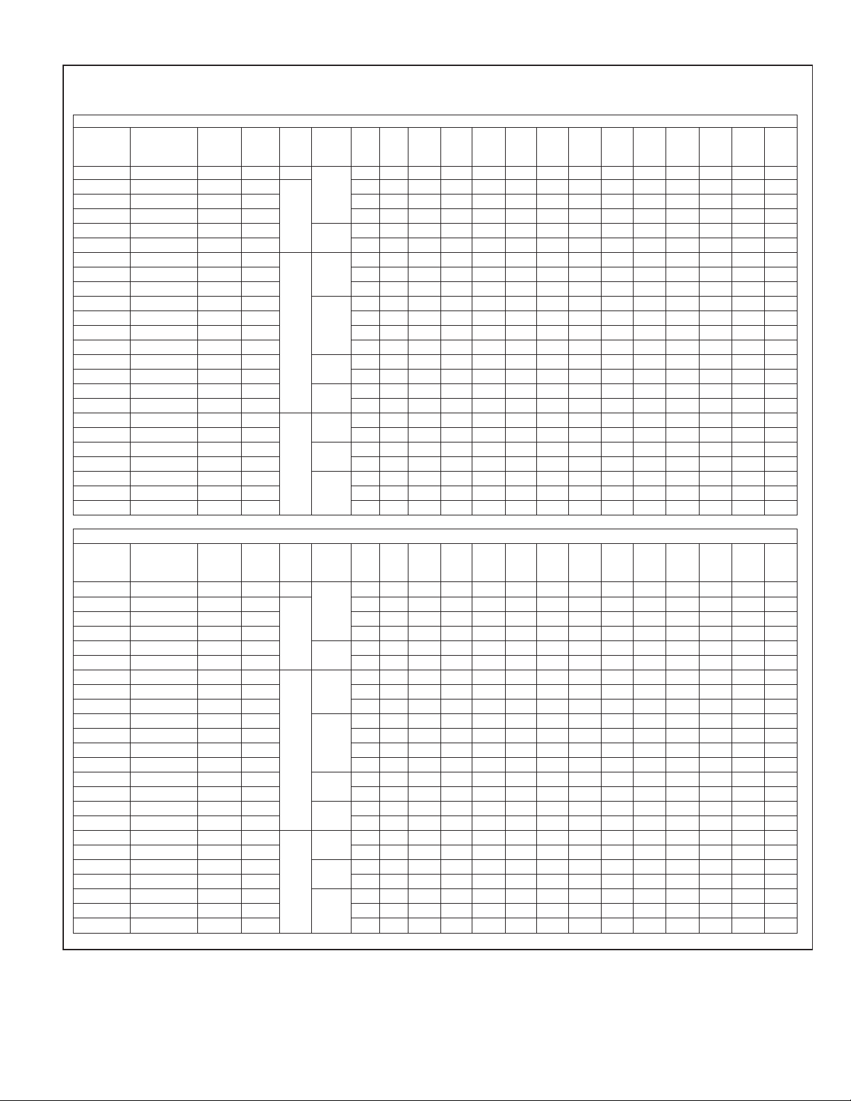
2.5B Coil Specifications: Airflow Pressure Drop
TABLE 1
AIRFLOW PRESSURE DROP
et Coil Static Pressure Drop (Inches W.C.) [kPa] CFM [L/s] - Coil-Only
Width
W
ominal
N
apacity
C
1.5 - 2
2.5 - 3
2
3
3.5 - 4
00
600
700
[283]
[330]
.120 0.157 0.199 0.246 ————————— —
0
.113 0.145 0.181 0.222 0.266 0.315 0.368 ———— —— —
0
.062 0.086 0.112 0.140 0.170 0.202 0.236 ———— —— —
0
.5 - 3
.106 0.125 0.146 0.169 0.194 0.221 0.251 0.282 0.315 0.350 0.386 0.425 0.466 —
0
.5 - 4
.036 0.050 0.065 0.081 0.098 0.117 0.137 0.158 0.180 0.203 0.228 0.254 ——
0
5
.062 0.086 0.112 0.140 0.170 0.202 0.236 0.272 0.309 0.349 0.391 0.434 0.480 —
0
[
8
378]
9
00
000
1100
1200
300
1400
1
425]
[
472]
[519]
[
[566]
[
1
614]
[661]
1500
[708]
1
755]
[
600
1700
[802]
1800
[850]
1
[
897]
Coil Model
(-)CF
-)CF2414STAM 600/900 [283/425] 4.56 [0.42] 16/2 14 0.165 0.209 0.262 0.325 ————————— —
(
-)CF2417STAM 600/900 [283/425] 4.56 [0.42] 16/2
(
-)CF2417SEAM 400/900 [283/425] 4.56 [0.42] 16/2 0.120 0.157 0.199 0.246 ————————— —
(
-)CF2417MTAM 600/900 [283/425] 5.70 [.052] 16/2 17 0.113 0.145 0.181 0.222 ——————————
(
-)CF3617STAM 700/1300 [330/614] 5.70 [0.52] 16/2
(
-)CF3617SEAM 400/1300 [330/614] 5.70 [0.52] 16/2 0.113 0.145 0.181 0.222 0.266 0.315 0.368 ———— —— —
(
-)CF2421MTAM 600/900 [283/425] 5.70 [0.52] 16/2 0.113 0.145 0.181 0.222 ——————————
(
-)CF2421MEAM 300/900 [283/425] 5.70 [0.52] 16/2 1.5-2 0.113 0.145 0.181 0.222 ——————————
(
-)CF2421HTAM 600/900 [283/425] 5.70 [0.52] 16/2 0.113 0.145 0.181 0.222 ——————————
(
-)CF3621STAM 700/1300 [330/614] 5.70 [0.52] 16/2 0.113 0.145 0.181 0.222 0.266 0.315 0.368 ———— — — —
(
-)CF3621MTAM 700/1300 [330/614] 8.55 [0.79] 16/2
(
-)CF3621MEAM 300/1300 [330/614] 8.55 [0.79] 16/2 21 0.062 0.086 0.112 0.140 0.170 0.202 0.236 ———— —— —
(
-)CF3621HTAM 700/1300 [330/614] 7.60 [0.70] 13/3 0.106 0.125 0.146 0.169 0.194 0.221 0.251 ——— — — — —
(
-)CF4821MTAM 1100/1800 [519/850] 7.60 [0.70] 13/3
(
-)CF4821STAM 1100/1800 [519/850] 8.55 [0.79] 16 / 2 0.062 0.086 0.112 0.140 0.170 0.202 0.236 0.272 0.309 0.349 0.391 0.434 0.480 0.527
(
-)CF6021STAM 1400/1600 [661/755] 7.60 [0.70] 13/3
(
-)CF6021SEAM 500/1600 [661/755] 7.60 [0.70] 13/3 0.036 0.050 0.065 0.081 0.098 0.117 0.137 0.158 0.180 0.203 0.228 0.254 ——
(
-)CF3624MTAM 700/1300 [330/614] 8.55 [0.79] 16/2 2.5 - 3 0.062 0.086 0.112 0.140 0.170 0.202 0.236 0.272 0.309 ———— —
(
-)CF3624HTAM 700/1300 [330/614] 9.98 [0.93] 14/3 0.036 0.050 0.065 0.081 0.098 0.117 0.137 0.158 0.180 ———— —
(
-)CF4824STAM 1100/1800 [519/850] 8.55 [0.79] 16/2
(
-)CF4824HTAM 1100/1800 [519/850] 9.98 [0.93] 14/3 24 0.036 0.050 0.065 0.081 0.098 0.117 0.137 0.158 0.180 0.203 0.228 0.254 0.281 —
(
-)CF6024STAM 1400/1800 [661/755] 9.98 [0.93] 14/3 0.036 0.050 0.065 0.081 0.098 0.117 0.137 0.158 0.180 0.203 0.228 0.254 0.281 —
(
-)CF6024HTAM 1400/1800 [661/755] 9.98 [0.93] 14/3 5 0.036 0.050 0.065 0.081 0.098 0.117 0.137 0.158 0.180 0.203 0.228 0.254 0.281 —
(
-)CF6024MEAM 500/1800 [661/755] 9.98 [0.93] 14/3 0.036 0.050 0.065 0.081 0.098 0.117 0.137 0.158 0.180 0.203 0.228 0.254 0.281 —
(
Approx. Design
Cooling Airflow
Range CFM/[L/s]
Face Area
Fins Per
Inch /
2 [m2
]
Ft.
Rows
Deep
900
Coil Model
(-)CF
(-)CF2414STAM 600/1600 [283/755] 4.56 [0.42] 16/2 14 0.118 0.118 0.145 0.176 0.210 0.247 0.288 0.332 0.379 0.429 0.483 —— —
(-)CF2417STAM 600/1500 [283/707] 4.56 [0.42] 16/2
(-)CF2417SEAM 400/1500 [283/707] 4.56 [0.42] 16/2 0.116 0.116 0.151 0.190 0.235 0.284 0.338 0.397 0.461 0.530 ————
(-)CF2417MTAM 600/1600 [283/755] 5.70 [.052] 16/2 17 0.101 0.101 0.129 0.161 0.196 0.235 0.277 0.323 0.373 0.425 0.482 ———
(-)CF3617STAM 600/1600 [283/755] 5.70 [0.52] 16/2 0.101 0.101 0.129 0.161 0.196 0.235 0.277 0.323 0.373 0.425 0.482 ———
(-)CF3617SEAM 400/1600 [283/755] 5.70 [0.52] 16/2
(-)CF2421MTAM 600/1600 [283/755] 5.70 [0.52] 16/2 0.101 0.101 0.129 0.161 0.196 0.235 0.277 0.323 0.373 0.425 0.482 —— —
(-)CF2421MEAM 300/1600 [283/755] 5.70 [0.52] 16/2 15.2 0.101 0.101 0.129 0.161 0.196 0.235 0.277 0.323 0.373 0.425 0.482 —— —
(-)CF2421HTAM 600/1600 [283/755] 5.70 [0.52] 16/2 0.101 0.101 0.129 0.161 0.196 0.235 0.277 0.323 0.373 0.425 0.482 —— —
(-)CF3621STAM 600/1600 [283/755] 5.70 [0.52] 16/2 0.101 0.101 0.129 0.161 0.196 0.235 0.277 0.323 0.373 0.425 0.482 ———
(-)CF3621MTAM 600/1900 [283/896] 8.55 [0.79] 16/2
(-)CF3621MEAM 300/1900 [283/896] 8.55 [0.79] 16/2 21 0.039 0.039 0.056 0.075 0.095 0.117 0.141 0.166 0.193 0.222 0.252 0.284 0.318 0.353
(-)CF3621HTAM 600/1900 [283/896] 7.60 [0.70] 13/3 0.043 0.043 0.053 0.066 0.080 0.096 0.115 0.135 0.158 0.182 0.208 0.237 0.267 0.299
(-)CF4821MTAM 600/1900 [283/896] 7.60 [0.70] 13/3 0.043 0.043 0.053 0.066 0.080 0.096 0.115 0.135 0.158 0.182 0.208 0.237 0.267 0.299
(-)CF4821STAM 600/1900 [283/896] 8.55 [0.79] 16/2
(-)CF6021STAM 600/1900 [283/896] 7.60 [0.70] 13/3
(-)CF6021SEAM 500/1900 [283/896] 7.60 [0.70] 13/3 0.080 0.080 0.092 0.106 0.121 0.136 0.153 0.171 0.190 0.211 0.232 0.254 0.278 0.302
(-)CF3624MTAM 600/1900 [283/896] 8.55 [0.79] 16/2
(-)CF3624HTAM 600/1900 [283/896] 9.98 [0.93] 14/3 0.023 0.023 0.038 0.055 0.074 0.095 0.119 0.144 0.171 0.200 0.231 0.264 0.300 0.337
(-)CF4824STAM 600/1900 [283/896] 8.55 [0.79] 16/2
(-)CF4824HTAM 600/1900 [283/896] 9.98 [0.93] 14/3 24 0.023 0.023 0.038 0.055 0.074 0.095 0.119 0.144 0.171 0.200 0.231 0.264 0.300 0.337
(-)CF6024STAM 600/1900 [283/896] 9.98 [0.93] 14/3 0.023 0.023 0.038 0.055 0.074 0.095 0.119 0.144 0.171 0.200 0.231 0.264 0.300 0.337
(-)CF6024HTAM 600/1900 [283/896] 9.98 [0.93] 14/3 0.023 0.023 0.038 0.055 0.074 0.095 0.119 0.144 0.171 0.200 0.231 0.264 0.300 0.337
(-)CF6024MEAM 500/1900 [283/896] 9.98 [0.93] 14/3 5 0.023 0.023 0.038 0.055 0.074 0.095 0.119 0.144 0.171 0.200 0.231 0.264 0.300 0.337
Approx. Design
Cooling Airflow
Range CFM/[L/s]
Face Area
Fins Per
Inch /
2
[m2]
Ft.
Rows
Deep
Dry Coil Static Pressure Drop (Inches W.C.) [kPa] CFM [L/s] - Coil-Only
00
600
Nominal
idth
W
Capacity
1.5 - 2
2.5 - 3
2.5 - 3
3.5 - 4
5
2.5 - 3
3.5 - 4
700
[283]
[330]
0.116 0.116 0.151 0.190 0.235 0.284 0.338 0.397 0.461 0.530 ——— —
0.101 0.101 0.129 0.161 0.196 0.235 0.277 0.323 0.373 0.425 0.482 ———
0.039 0.039 0.056 0.075 0.095 0.117 0.141 0.166 0.193 0.222 0.252 0.284 0.318 0.353
0.039 0.039 0.056 0.075 0.095 0.117 0.141 0.166 0.193 0.222 0.252 0.284 0.318 0.353
0.080 0.080 0.092 0.106 0.121 0.136 0.153 0.171 0.190 0.211 0.232 0.254 0.278 0.302
0.039 0.039 0.056 0.075 0.095 0.117 0.141 0.166 0.193 0.222 0.252 0.284 0.318 0.353
0.039 0.039 0.056 0.075 0.095 0.117 0.141 0.166 0.193 0.222 0.252 0.284 0.318 0.353
800
[378]
9
[425]
1000
[472]
100
1
[519]
1200
[566]
1300
[614]
400
1
[661]
1500
[708]
1600
[755]
1700
[802]
1800
[850]
900
1
[897]
[ ] Designates Metric Conversion
IMPORTANT NOTE: Gas furnace heating CFM can exceed the design cooling CFM. Ductwork and coil selection must accommodate the higher of the cooling or gas heating CFM to prevent furnace limit tripping, excessive noise, and
coil freeze-up.
7
Page 8
3.0 INSTALLATION
3.1 APPLICATIONS
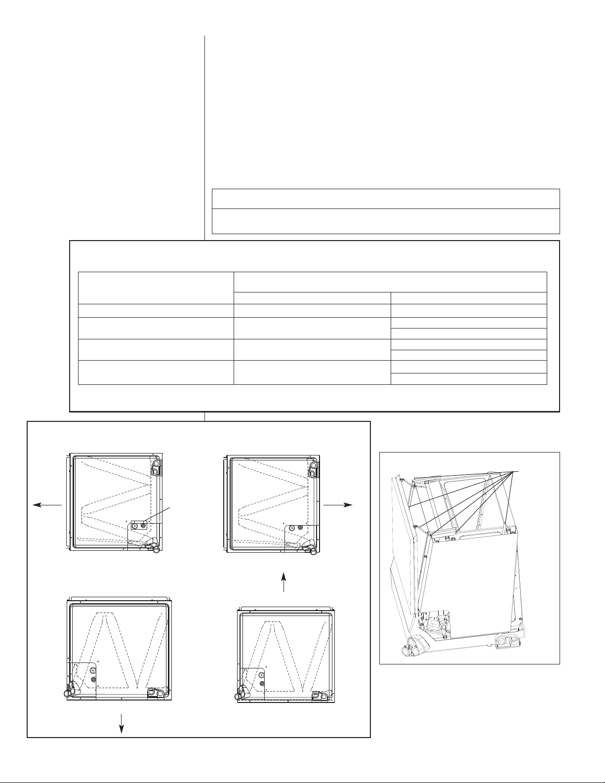
(-)CF cased coils can be applied in upflow, downflow, horizontal right and horizontal left
applications without modifications. (-)CF uncased coils can only be applied in upflow and
ownflow applications as received (see Table 2 and Figure 3). For horizontal applications
d
of uncased replacement coils, installation of a horizontal drip shield and water management parts from old coil is required. (Also see Section 5.2: Horizontal Adapter Kit.)
For coils that are two sizes larger than the furnace, for example, a 21ⴖ wide coil on a 14ⴖ
furnace, a tapered adaptor with a minimum height of 6ⴖ is required to evenly distribute
airflow. See Figure 5. For coils that are one size larger than the furnace; for example a
21ⴖ wide coil on a 17
use the specified adapter kit (RXBA-AC). See Figure 6.
CAUTION
For horizontal applications, the horizontal drain pan must be located under the
indoor coil. Failure to place the pan under the coil can result in property damage.
TABLE 2
COIL APPLICATION
Coil Model (-)CF
2414S 2417S 2417M 3617S 2417H
2417S 2417M 3617S
2417H
2421M 3621S 3621M 4821S
2421H 4821S 3621H 4821M 6021S
3624H 4824H 6024H 3624M
6024S 4824S
*Due to the proximity of the drain pan to the high temperature oil furnace drum, horizontal left application is NOT
permitted on all oil furnaces.
1
⁄2ⴖ furnace, seal the gap between the two units with sheet metal, or
Furnace Width
(In.) [mm]
Oil*
— 14 [356]
17 [431]
21 [533]
1
24
⁄2 [622]
Gas
171⁄2 [444]
14 [356]
21 [533]
171⁄2 [444]
1
⁄2 [622]
24
21 [533]
FIGURE 3
COIL INSTALLATION OPTIONS
AIRFLOW
HORIZONTAL LEFT
DOWNFLOW
AIRFLOW
PRESSURE
SENSITIVE
GASKET
HORIZONTAL RIGHT
IMPORTANT: Coil must be
installed on the supply airflow
side of a gas or oil furnace.
AIRFLOW
UPFLOW
AIRFLOW
FIGURE 4
PARTS
TO BE
REUSED ON
HORIZONTAL
COILS ONLY.
ST-A1213
8
Page 9
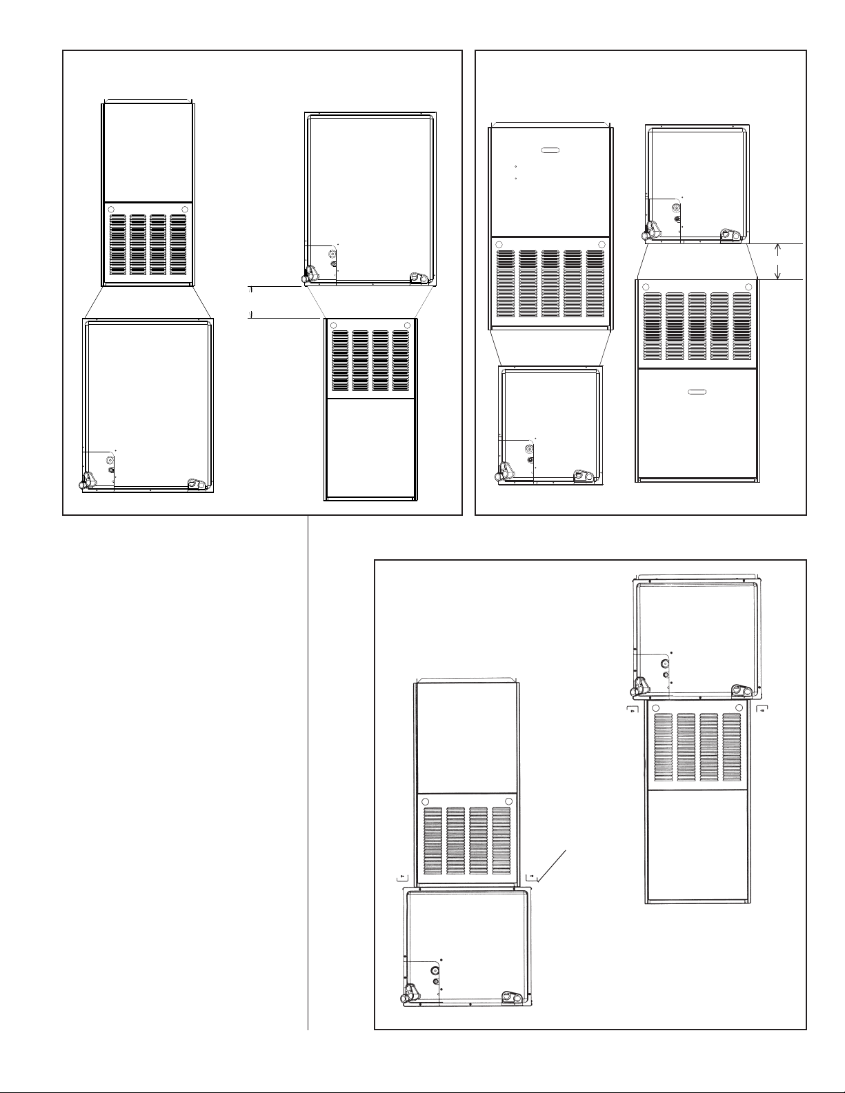
FIGURE 5A
NSTALLATION OF COIL MATCHED WITH A FURNACE TWO SIZES SMALLER
I
6.000
MINIMUM
FIGURE 5B
NSTALLATION OF COIL MATCH WITH A FURNACE ONE SIZE
I
MALLER
S
6” MINIMUM
FIGURE 6
INSTALLATION OF COIL MATCHED WITH
A FURNACE OF SMALLER SIZE
DOWNFLOW OR
HORIZONTAL
RIGHT APPLICATION
RXBA-AC
PLENUM
ADAPTER
UPFLOW OR HORIZONTAL
LEFT APPLICATION
When a cooling coil is matched with a gas furnace of one smaller size, always center coil
over the furnace.
IMPORTANT: Seal the gap between the two
units with appropriate sheet metal parts, or use
the adapter kit RXBA-AC (Upflow/Horizontal).
9
Page 10
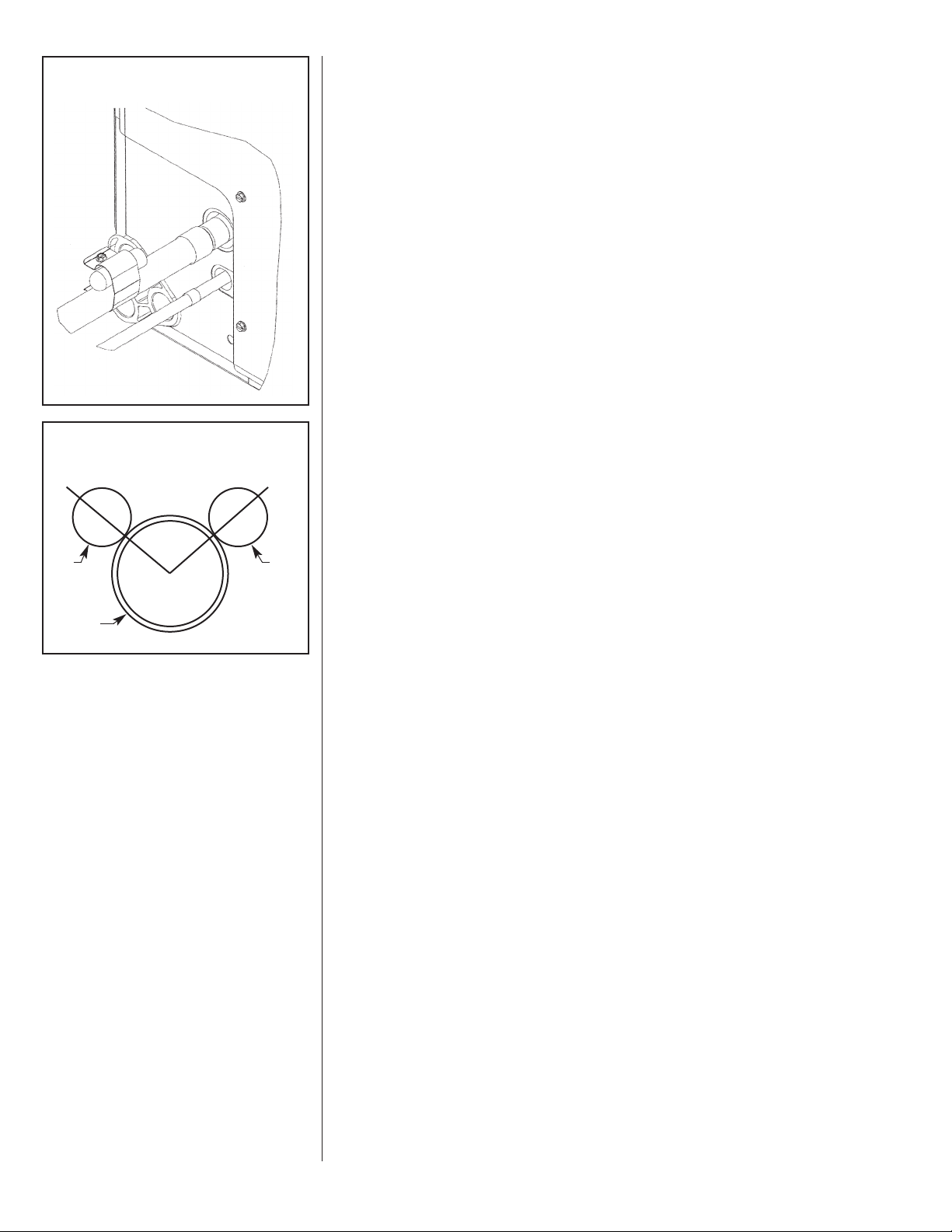
FIGURE 7
ULB LOCATION
B
FIGURE 8
BULB LOCATION
10 O’CLOCK
2 O’CLOCK
3.2 REFRIGERANT CONNECTIONS
Keep the coil connections sealed until refrigerant connections are to be made. See the
Installation Instructions for the outdoor unit for details on line sizing, tubing installation,
and charging information.
Coil is shipped with a low (5 - 10 PSIG) pressure charge of dry nitrogen. Evacuate the
ystem before charging with refrigerant.
s
Install refrigerant tubing so that it does not block service access to the front of the unit.
Nitrogen should flow through the refrigerant lines while brazing.
Use a brazing shield to protect the cabinet’s paint from being damaged by torch flames.
After the refrigerant connections are made, seal the gap around the connections with
pressure sensitive gasket. If necessary, cut the gasket into two pieces for a better seal
(See Figure 3.)
3.3 TEV SENSING BULB
IMPORTANT: DO NOT perform any soldering with the TEV bulb attached to any line.
After soldering operations have been completed, clamp the TEV bulb securely on the
suction line at the 10 to 2 o’clock position with the strap provided in the parts bag.
Insulate the TEV sensing bulb and suction line with the provided pressure sensitive insulation (size 4” x 7”) and secure with provided wire ties.
IMPORTANT: TEV sensing bulb should be located on a horizontal section
of copper suction line, just outside of coil box. The copper sensing bulb
must never be placed on any aluminum tube as this will result in galvanic
corrosion and eventual failure of the aluminum tube.
B
ULB
VAPOR
LINE
3.4 ELECTRONIC EXPANSION
The RCF EXV equipped coils, cased and uncased, are the first Rheem indoor products
ULB
B
to be produced with the noncommunicating, stand-alone EXV control. One of the biggest
advantages of an EXV is the control can intelligently change the EXV position based on
system demands other than just suction line temperature. By the measurement of the
suction pressure via the vapor line pressure transducer (factory installed) and the vapor
line thermister (field connected to the vapor line, but factory provided within the air handler) the EcoNet™ enabled air handler control calculates the suction superheat at the
indoor coil. This calculation permits the air handler control to make decisions for when to
open and close the electronic expansion valve for the purpose of maintaining a predetermined suction superheat. The electronic valve is equipped with a 4-pole removable
external stator, and inlet and outlet Chatleff fittings for optimal serviceability. These
valves also have an internal check valve to provide heat pump compatibility. When operating in heating mode, the air handler control will open the electronic valve completely to
permit the check valve to operate and maximize reverse refrigerant flow.
3.5 EXV VAPOR LINE THERMISTER
IMPORTANT: DO NOT perform any brazing with the vapor line thermister attached to
any line. After brazing operations have been completed, clamp the vapor line thermister
securely on the vapor line at the 10 to 2 o’clock position with the clip provided on the
thermister. Insulate the vapor line thermister and vapor line with the provided pressure
sensitive insulation (size 4” x 7”) and secure with provided wire ties.
Make sure to protect the EXV pressure transducer, vapor thermister, copper to aluminum joint, and service valves from overheating by use of wet rag or some type
of shielding. Double tip torches are not recommended.
IMPORTANT: Vapor line thermister should be located on a horizontal section of
vapor line, just outside of coil box. The copper thermister must never be placed
on any aluminum tube as this will result in galvanic corrosion and eventual failure of the aluminum tube.
IMPORTANT: Never place the thermister on the heat effected zone near the braze
connection, but it should be located within 6” of the indoor unit.
10
Page 11
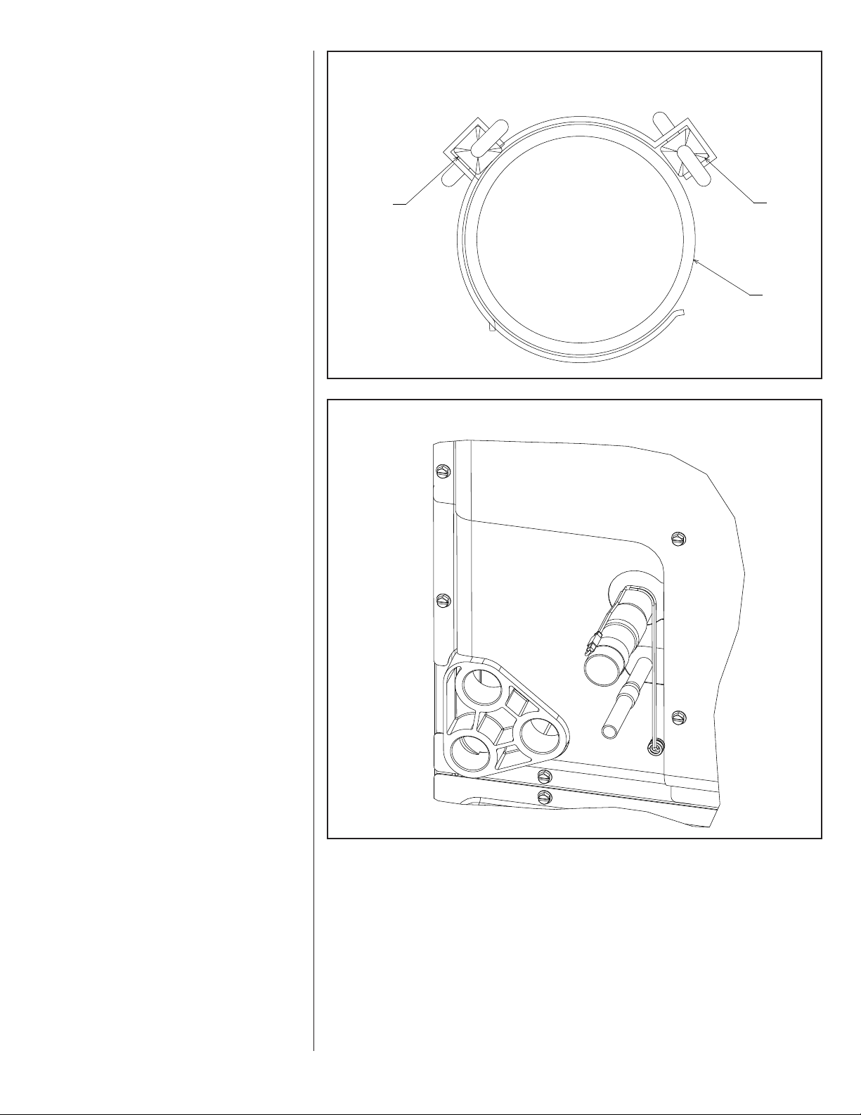
FIGURE 9
1
0 O’CLOCK
2 O’CLOCK
VAPOR LINE
T
HERMISTOR
VAPOR LINE
THERMISTOR
V
APOR LINE
THERMISTER LOCATION
FIGURE 10
THERMISTER LOCATION
11
Page 12
3.6 FACTORY PROGRAMMED SUPERHEAT
2
3
2
3
2
3
2
3
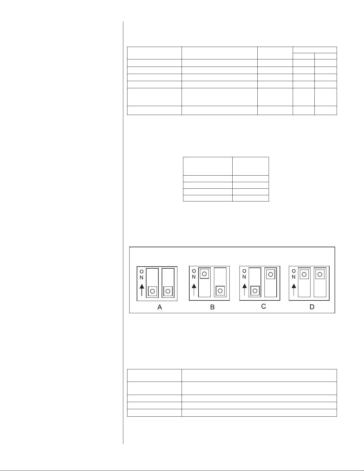
The stand alone EXV control is pre-programmed for 10°F superheat. The following dip
switch settings must be set at the time of coil installation.
Air Handler
RCF2417SE RP1724 6 ON OFF
RCF2421ME RA1724, RA2024, RP2024 6 ON OFF
RCF3617SE RP1736 6 ON OFF
RCF3621ME RA1736 8 OFF ON
RCF6021SE RA2036, RA2048, RA2060 6 ON OFF
RCF6024ME RA1660 6 ON OFF
Outdoor Unit
RA1748
RP2036, RP2048, RP2060
Superheat
(°F)
Dipswitch Settings
2
3
3.7 SUPERHEAT OFFSET DIP SWITCH SETTINGS
Although the above superheat set point is considered to be the most efficient set point
for each air handler, installation conditions can drastically effect the measurement of
superheat by the air handler control. For this reason the following dip switch settings
have been provided to enable flexibility for various installation conditions.
Superheat Offset
Selection Profile
A 10
B6
C8
D 12
Superheat
Setting (°F)
3.8 EXV STEP DIP SWITCH
The EXV dip switch has an optional 500 or 1600 steps setting. This dipswitch should
currently be in the 500 step position only. Rheem does not currently supply 1600 step
EXV’s. The dipswitch makes the control forward compatible with a 1600 step EXV for
possible future use.
3.9 DIAGNOSTICS
There are 2 LEDs (green/yellow) on the standalone EXV control which indicate valve
movement. When the green LED is illuminated, the control is moving the valve in the
open direction. When the yellow LED is illuminated, the control is moving the valve in the
closed direction. When neither LED is illuminated, the valve is not being moved by the
control. In addition to the diagnostic lights on the control, it is possible to feel the coil on
the EXV pulse when the control is attempting to change the EXV position.
12
Status LED
1
2 No Valid Suction Temperature
3 Valve near open position
4 Suction pressure out of range
Only suction temperature valid – suction pressure nor coil
temperature are valid
Board Fault
Page 13
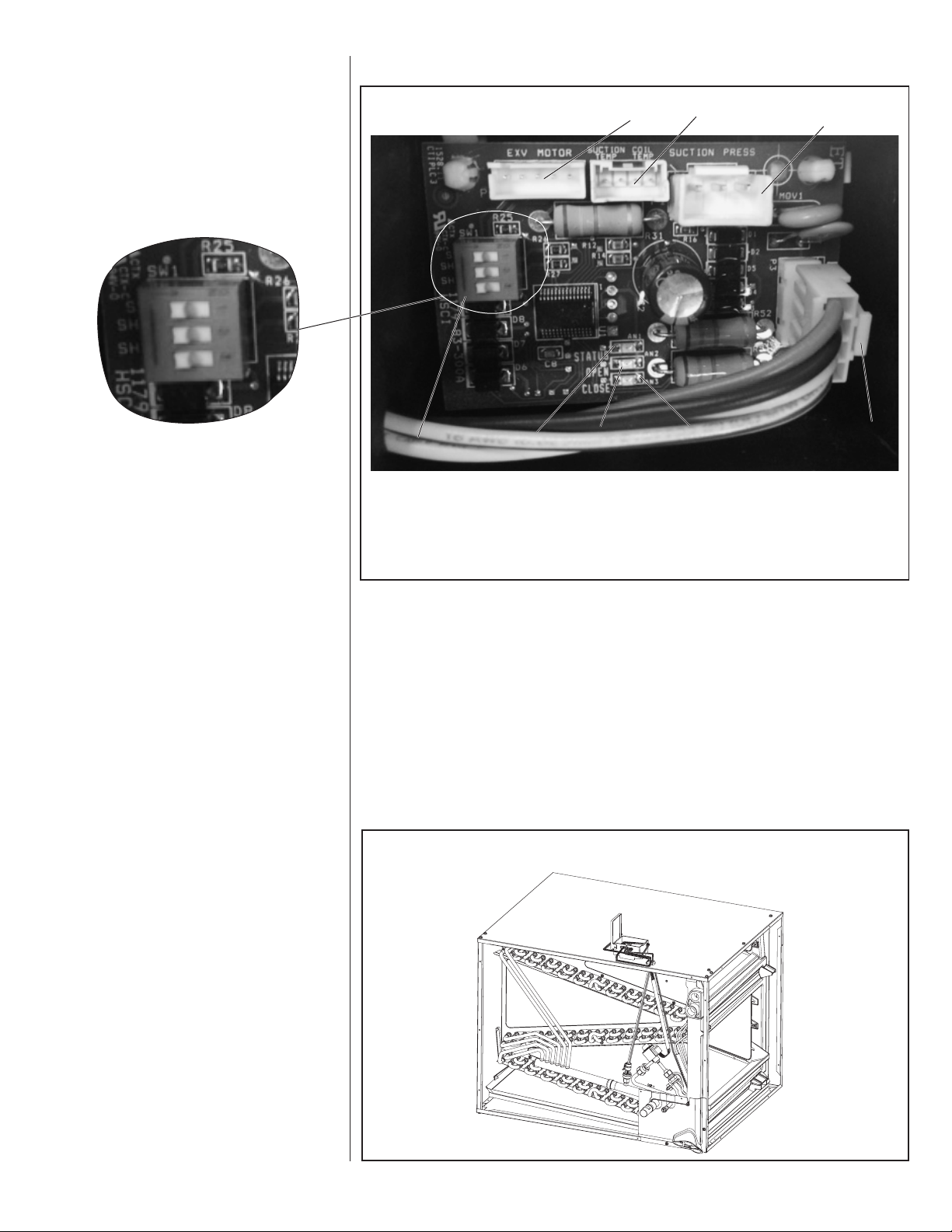
3.10 “EXV STANDALONE CONTROL” PHYSICAL INTERFACE
NOTE: Switches are in “OFF”
position.
FIGURE 11
XV ENABLED COIL WIRING DIAGRAM
E
SWITCHES IN AN “OFF” POSITION
5
1. Thermostat Connection
2. Yellow LED (close)
3. Green LED (open)
4. Red LED (status)
5. Dip Switch (EXV steps, 2 & 3 SH adjustment dip switch)
4
6
3
6. Electronic Expansion Valve Connection
7. Suction and Coil Thermistor Connection
8. Suction Pressure Transducer Connection
7
2
8
1
3.11 EXV STANDALONE CONTROL OPTIONAL MOUNTING
3.11 LOCATIONS
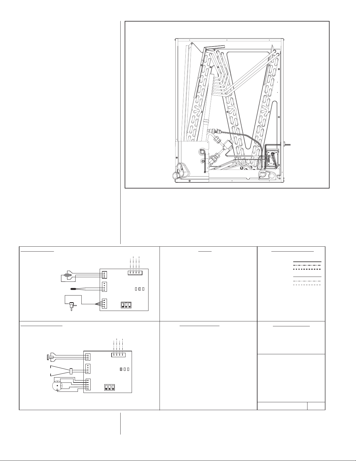
The EXV standalone control and housing is factory installed inside the case on the tube
sheet. This location has been tested and approved for long term operation inside the
highly humid environment. In the event servicing the EXV control without opening the
coil door or to see the operational lights while the system is in operation the following
alternate control and housing location is approved. The mounting location will require
the wiring harnesses to be disconnected from the control, the control removed from the
housing and the housing mounting screws removed. The wires will need to be routed
through the knockout (there is one knockout per side) and then the assembly reassembled externally to the coil case.
IMPORTANT: It is recommended to place aluminum tape over the screw holes in the
tube sheet to prevent bypass air.
FIGURE 12
OPTIONAL CONTROL INSTALLATION LOCATION
ST-A1246-01_S2
13
Page 14
WIRING DIAGRAM
RCY1
Y
2
EXV
MOTOR
SUCTION
PRESSURE
SUCTION
TEMP.
COIL
TEMP.
R
BR
Y
Y/BL
STATUS
OPEN
CLOSE
SS SH1 SH2
RCY1
Y2
EXV
MOTOR
SUCTION
PRESSURE
SUCTION
TEMP.
COIL
TEMP.
R
BR
Y
Y/BL
GND
T M
SCHEMATIC DIAGRAM
STATUS
OPEN
CLOSE
SS SH1 SH2
90-101897-09
REV:PART NO.:
00
WIRING INFORMATION
WARNING
-CABINET MUST BE PERMANENTLY GROUNDED
AND CONFORM TO I.E.C., N.E.C., C.E.C.,
NATIONAL WIRING REGULATIONS, AND LOCAL
CODES AS APPLICABLE.
REPLACEMENT WIRE
-MUST BE THE SAME SIZE AND TYPE
OF INSULATION AS ORIGINAL (105C. MIN.)
-FIELD INSTALLED
-
FACTORY STANDARD
LOW VOLTAGE
-FIELD INSTALLED
-
FACTORY OPTION
-FACTORY STANDARD
LINE VOLTAGE
WIRE COLOR CODE
BK......BLACK
BR......BROWN
BL.......BLUE
G........GREEN
GY......GRAY
O........ORANGE
PR......PURPLE
R........RED
W.......WHITE
Y........YELLOW
NOTES
1.....
2.....
3.....
CONNECTORS SUITABLE FOR USE WITH COPPER CONDUCTORS
ONLY.
LOW VOLTAGE CIRCUIT TO BE N.E.C. CLASS 2 WITH A C LASS 2
TRANSFORMAER 24 VOLT, 50 OR 60 HZ. MIN 18 AWG.
TO THERMOSTAT, REFER TO SYSTEM SCHEMATI CS OR
SCHEMATI CS ON FURNACE FOR LOW VOLTAGE CONTROL
WIRING.
CLOSE..............................YELLOW LED
COIL TEMP........... ............COIL I NLET THERMISTER CONNECTION
COMP...............................COMPRESSOR
EXV (5 PIN).......................ELEC. TX VALVE
ODF...................................OUTDOOR FAN CONNECTION
OPEN................................GREEN LED
SH1...................................SUPERHEAT OFFSET SWITCH 1
SH2....................................SUPERHEAT OFFSET SWITCH 2
SS......................................EXV STEP SELECTION (MUST REMAIN OFF)
STATUS..............................RED LED
SUCTION PRESSURE.......SUCTION PRESS. TRANSDUCER CONN.
SUCTION TEMP. ...............VAPOR LINE THERMISTOR CONN.
TM ......................................THERMISTOR
RVS.......................... ...........REVERSING VALVE CONN.
COMPONENT CODES
ELECTRICAL WIRING
DIAGRAM
NON-COMMUNICATING
STANDALONE
EXV CONTROL W/
PRESSURE TRANSDUCER
FIGURE 13
FACTORY CONTROL INSTALLATION LOCATION
ST-A1246-01_S1
3.12 EXV STANDALONE WIRING
For proper operation the standalone EXV control requires 24VAC power and staged
operation thermostat signals. The following diagram should be used to connect the flying leads provided with the cased coil to the thermostat wiring. When employed with the
Econet™ Communicating System attach the flying leads provided with the cased coil to
the legacy thermostat outputs on the Econet™ compatible IFC.
14
Page 15
3.13 FLOW CHECK PISTON
NOTICE
!
FOR PROPER SYSTEM OPERATION, IT MAY BE NECESSARY TO
REPLACE THE PISTON INSTALLED IN THE INDOOR COIL. CHECK THE
ERVICE VALVES ON THIS UNIT TO SEE IF A NOTICE TAG ALONG WITH A
S
PLASTIC BAG CONTAINING A PISTON IS ATTACHED. IF ONE IS PRESENT
A CHANGE OF THE PISTON IS REQUIRED. FAILURE TO CHANGE THE
PISTON CAN RESULT IN IMPROPER PERFORMANCE OF THE SYSTEM.
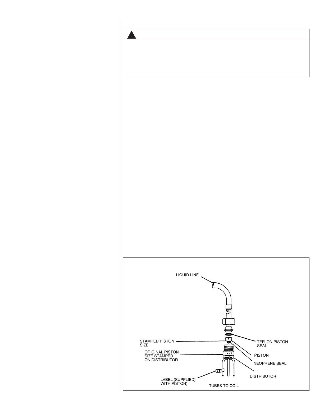
The flow check piston is a multi-purpose device. With flow into the compression nut end
from the liquid line, the piston is in a check position and acts as the expansion device
with flow through the metering orifice in the center of the piston. The “O” ring on the
end of the piston prevents refrigerant from bypassing the metering orifice. Flow from the
metering orifice is centered into a distributor which serves to evenly distribute refrigerant to the evaporator circuits. With flow in the reverse direction (direction of arrows on
the distributor body), the piston is forced off the seat and liquid from the condenser is
allowed to free flow around the piston.
It is essential that the heat pump indoor and outdoor sections be properly matched. Use
only matched components as shown in sales specification sheets.
A piston size that is too small will cause starving and one that is too large will cause
flooding. In either case, system performance, reliability and charge balance (heating
and cooling) will be unacceptable.
Change the piston in the distributor on the indoor coil before installing the coil and
charging the system following the procedure below:
• Using a back-up wrench on the distributor body, loosen the compression nut to gain
access to the piston.
• Using the wire provided with replacement pistons, run (hooked end) through hole in
piston.
• Hook nose end of piston and lift gently from distributor body.
• Replace piston with one of proper size (see Table 4), install piston with gasket end of
piston in distributor. Do not force piston into distributor.
• NOTE: With piston in distributor, seal end should be down and should not be seen
looking in end of distributor. Piston must be free to rotate and move up and down.
Make sure piston is free to move in distributor body.
• Insure distributor gasket is located properly in the distributor body.
• Replace compression nut using back-up wrench on distributor body. Torque compression nut end with 8 to 10 ft. lbs.
FIGURE 14
PISTON AND DISTRIBUTOR ASSEMBLY
15
Page 16
• Original piston size is stamped on outside of distributor body. Remove new piston
size label from poly bag new piston came in and install new size label on outside of
distributor tube.
• Check fittings for leaks after installation, evacuation and charging is complete.
IMPORTANT: Do not attempt to drill pistons to size in the field. Metering holes have a
special chamfered inlet and cannot be modified.
IMPORTANT: Do not replace the neoprene “O” ring on the piston with any type of seal.
ontact the parts department for the exactly replacement of “O” ring.
C
3.14 CONDENSATE DRAIN TUBING
Consult local codes or ordinances for specific requirements.
IMPORTANT: When making drain fitting connections to the drain pan, use a thin layer of
Teflon paste, silicone or Teflon tape and install hand tight.
IMPORTANT: When making drain fitting connections to drain pan, do not overtighten.
Overtightening fittings can split pipe connections on the drain pan.
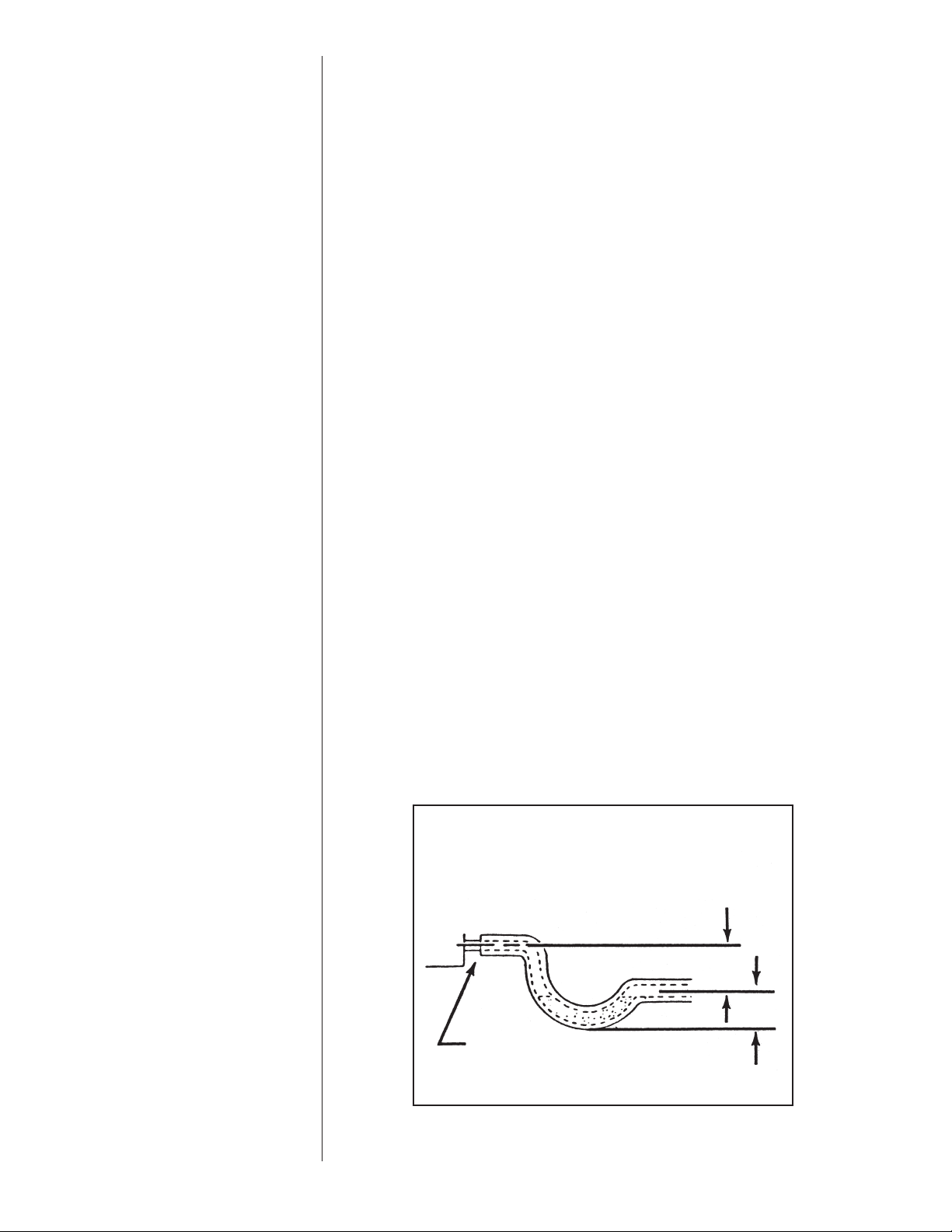
• Install drain lines so they do not block service access to front of the unit. Minimum
clearance of 24 inches is required for filter, coil or blower removal and service access.
• Make sure unit is level or pitched slightly toward primary drain connection so that
water will drain completely from the pan. (See Figure 15.)
• Do not reduce drain line size less than connection size provided on condensate drain
pan.
• All drain lines must be pitched downward away from the unit a minimum of 1/8” per
foot of line to ensure proper drainage.
• Do not connect condensate drain line to a closed or open sewer pipe. Run conden-
sate to an open drain or outdoors.
• The drain line should be insulated where necessary to prevent sweating and damage
due to condensate forming on the outside surface of the line.
• Make provisions for disconnecting and cleaning of the primary drain line should it
become necessary. Install a 3 in. trap in the primary drain line as close to the unit as
possible. Make sure that the top of the trap is below connection to the drain pan to
allow complete drainage of pan (See Figure 14).
• Auxiliary drain line should be run to a place where it will be noticeable if it becomes
operational. Occupant should be warned that a problem exists if water should begin
running from the auxiliary drain line.
• Plug the unused drain connection with the plugs provided in the parts bag, using a
thin layer of teflon paste, silicone or teflon tape to form a water tight seal.
• Test condensate drain pan and drain line after installation is complete. Pour water into
drain pan, enough to fill drain trap and line. Check to make sure drain pan is draining
completely, no leaks are found in drain line fittings, and water is draining from the termination of the primary drain line.
16
FIGURE 15
CONDENSATE DRAIN TRAP
DO NOT OPERATE UNIT WITHOUT
CONDENSATE DRAIN TRAP.
UNIT
3''
3''
DO NOT OVERTIGHTEN DRAIN FITTING
UNIT MUST BE SLIGHTLY INCLINED
TOWARD DRAIN CONNECTION.
Page 17
TABLE 3
HORIZONTAL ADAPTER KIT
Coil Model
(-)CF2414STAVUA RXHH-A01
(-)CF2417STAVUA RXHH-A02
(-)CF2417SEAVUA RXHH-A03
(-)CF2417STAVUA RXHH-A03
(-)CF2421SEAVUA RXHH-A03
(-)CF2421STAVUA RXHH-A03
(-)CF3617SEAVUA RXHH-A03
(-)CF3617STAVUA RXHH-A03
(-)CF3621HTAVUA RXHH-A06
(-)CF3621MEAVUA RXHH-A04
(-)CF3621STAVUA RXHH-A03
(-)CF3621STAVUA RXHH-A04
(-)CF3624STAVUA RXHH-A04
(-)CF4821STAVUA RXHH-A04
(-)CF4824STAVUA RXHH-A04
(-)CF6024STAVUA RXHH-A05
(-)CF2417HTAVUA RXHH-A03
(-)CF2421HTAVUA RXHH-A03
(-)CF3624HTAVUA RXHH-A05
(-)CF4821MTAVUA RXHH-A06
(-)CF4824HTAVUA RXHH-A05
(-)CF6021SEAVUA RXHH-A06
(-)CF6021STAVUA RXHH-A06
(-)CF6024MEAVUA RXHH-A05
(-)CF6024HTAVUA RXHH-A05
(-)CF2417SPAVUA RXHH-A02
(-)CF3617SPAVUA RXHH-A03
(-)CF3621SPAVUA RXHH-A03
(-)CF4821SPAVUA RXHH-A04
(-)CF4824SPAVUA RXHH-A04
Horizontal Adapter
Kit Model No.
3.15 DUCT FLANGES
Field-installed duct flanges (4 pieces) are shipped with units. Install duct flanges as
needed on top or bottom of the coil casing. (See Figure 16.)
CAUTION
It is recommended that an auxiliary/secondary drain pan be installed under units
containing evaporator coils that are located in any area of a structure where
damage to the building or building contents may occur as a result of an overflow
of the coil drain pan or a stoppage in the primary condensate drain piping.
3.16 COIL END SHIELDS
All uncased replacement coils come equipped from the factory with sheet metal shields
at the front and rear of the coil. The purpose of these shields is to isolate the aluminum
tubing from copper residue left on the foil insulation by the original copper tube coil.
Copper residue or copper oxide in contact with the aluminum tubing in the presence of
moisture will result in galvanic corrosion and leaks in the aluminum tube at the contact
point. The shields must be in place on the coil when replacing a copper tube coil to prevent the galvanic corrosion.
4.0 MAINTENANCE
WARNING
!
These instructions are intended as an aid to qualified licensed service personnel for proper installation, adjustment and operation of this unit. Read these
instructions thoroughly before attempting installation or operation. Failure to
follow these instructions may result in improper installation, adjustment,
service or maintenance possibly resulting in fire, electrical shock, property
damage, personal injury or death.
For continuing high performance and to minimize possible equipment failure, it is essential that annual maintenance be performed on this equipment. Consult your local dealer
as to the availability of a maintenance contract.
4.1 AIR FILTER
Check the system filter every ninety days or as often as found to be necessary and if
obstructed, clean or replace at once.
IMPORTANT: Do not operate the system without a filter in place.
4.2 INDOOR COIL - DRAIN PAN - DRAIN LINE
Inspect the indoor coil once each year for cleanliness and clean as necessary. In some
cases, it may be necessary to remove the filter and check the return side of the coil
with a mirror and flashlight.
IMPORTANT: Do not use caustic household drain cleaners or bleach in the condensate
pan or near the indoor coil. Drain cleaners will quickly damage the indoor coil.
17
Page 18
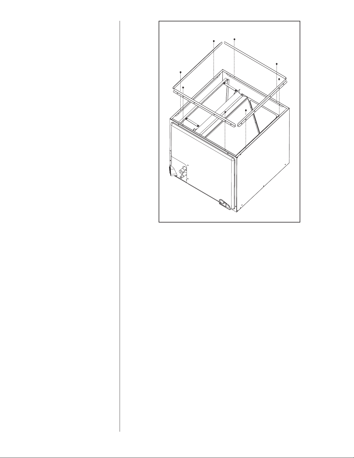
FIGURE 16
FIELD-INSTALLED DUCT FLANGES
5.0 ACCESSORIES
5.1 PLENUM ADAPTER ACCESSORY
RXBA-AE
This plenum adapter accessory is for use with the 24-1/2” wide cased indoor cooling and
heat pump coils. This allows a 24-1/2 wide cased coil to be installed on a 28” wide oil
furnace. This is a field-installed accessory only.
RXBA-AC
This plenum adapter accessory is for installation on cased indoor cooling and heat pump
coils. This allows a nominal size cased coil to be installed on the next smaller size gas or
oil furnace. NOTE: This accessory is for installation on coil casings to fit gas or oil
furnaces only - this accessory must not be used on electric furnaces or heat pump
air handlers. Consult the installation instructions packaged with the accessory for proper
installation.
18
Page 19
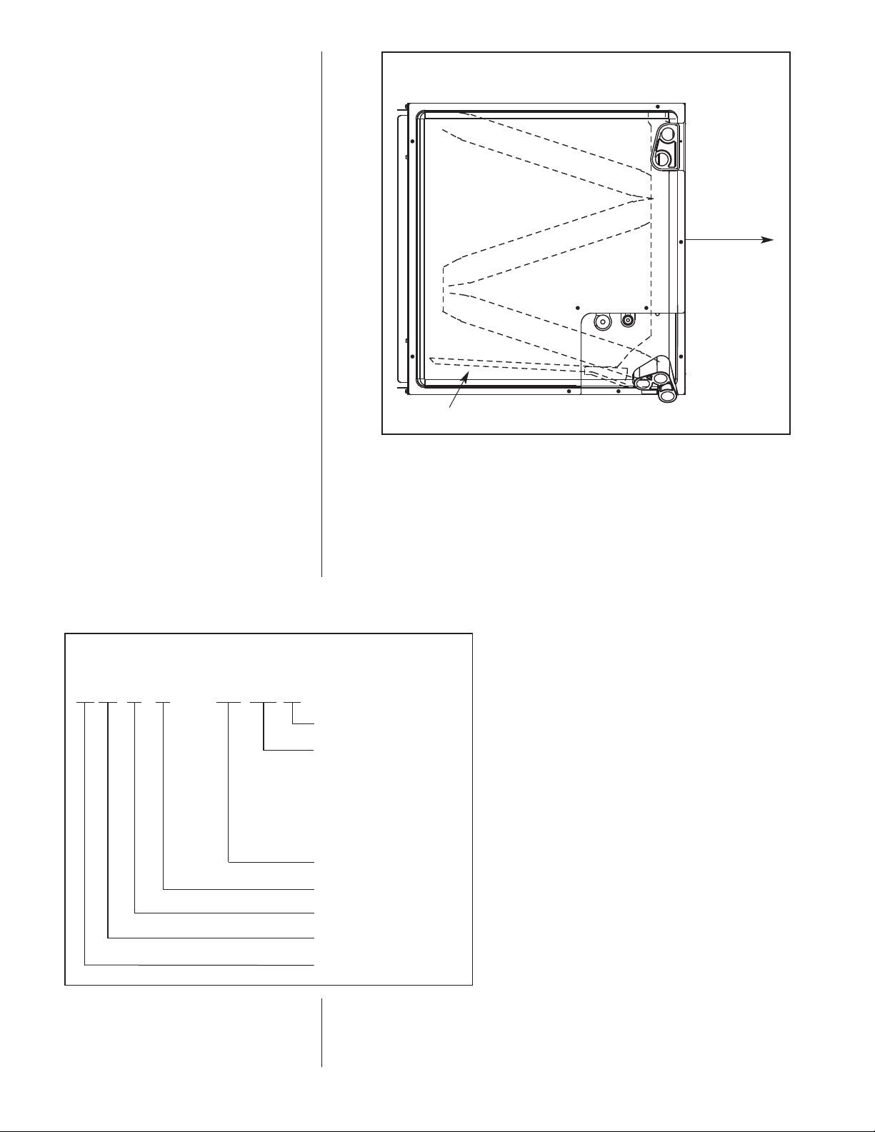
FIGURE 17
ORIZONTAL ADAPTER KIT ILLUSTRATION
H
AIRFLOW:
HORIZONTALDUAL
DIRECTION
HORIZONTAL ADAPTER KIT (RXHH-)
5.2 HORIZONTAL ADAPTER KIT RXHH- (See Figure 17)
This horizontal adapter kit is used to convert an upflow or downflow coil for a horizontal
application. See Table 3 to order the proper horizontal adapter kit.
5.3 INDOOR COIL CASING RXBC - (See Figure 18 & Table 4)
FIGURE 18
MODEL NUMBER EXPLANATION
RX B C — D14A I
INSULATION
CABINET WIDTH
14A = 14.0” 2 TON
17A = 17.5” 2 & 3 TON
21A = 21.0” 3 TON
21B = 210” 4 TON
21C = 21.0” A - COIL (3-5 TON)
24A = 24.5” 4 & 5 TON
DESIGN SERIES
D = 13 SEER COIL
COIL CASING
BLOWER UNIT
ACCESSORY
TRADE NAME
19
Page 20
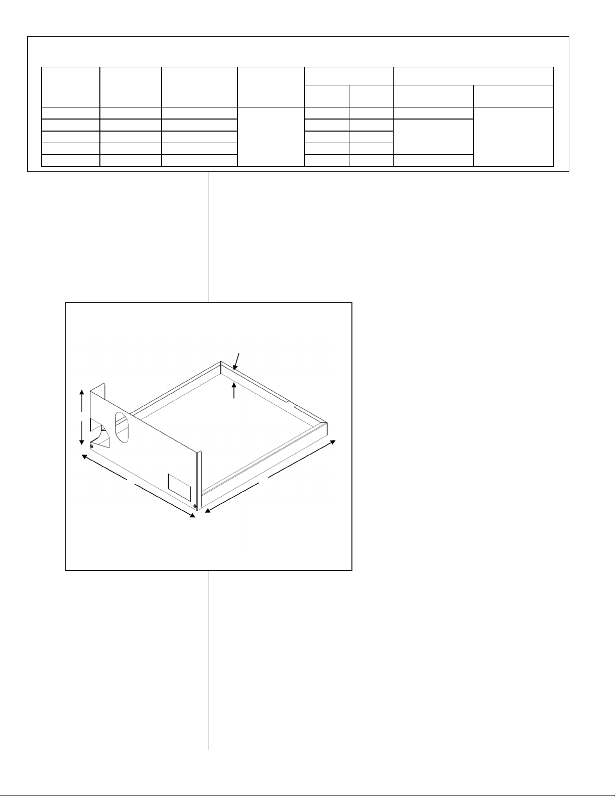
TABLE 4
!"#$%&'
()*+,'-.$/
0%#1'!&'
()*+,'-.$/
!#2&%'(#3,'-44/ 5"1&%'(#3,'-44/
6
789:5;<=> (;<';?@,'-AAB/ (@C,'-BCD/ (;D,'-D/ (@E,'-;C/ (;F';?@,'-A;G/
6789:5@;=> (@;,'-BEE/ (@C,'-BCD/ (@C,'-G/ (@F,'-;@/
6789:5@;8> (@;,'-BEE/ (@D,'-<;;/ (@D,'-FA/ (EA,'-<</
6789:5@;9> (@;,'-BEE/ (EA';?@,'-D<F/ (EE,'-<B/ (EG,'-DD/
6789:5@;=> (@A';?@,'-F@@/ (E@';?@,'-D@F/ (EA,'-;B/ (AA,'-@C/ (@E';?@,'-BG</
(@;''B?D,'-BAG/
(;G'E;?E@,'-BC</
@C'-BCD/
H3#&'!"#$%&
IJ2")'
KL4*"M
!#2&%'(#3,'
-44/
N"#$%&'(#3,'-44/
5"1&%'(#3,'-44/
0L11)O'=#M'?'6"&LM3'=#M'P1"3#3$+
NIT DIMENSIONS & WEIGHTS — RXBC- INDOOR COIL CASINGS
U
5.4 UNCASED COIL ADAPTER KIT
RXBA- (See Figure 19 & 20)
This uncased coil adapter kit is used to adapt the coil to a furnace or ductwork. See
Table 5 to order the proper adapter kit. Each kit contains a quantity of 20 adapters.
FIGURE 19
NCASED COIL ADAPTER KIT ILLUSTRATION
U
7.7
1.6
A
20.3
20
Page 21
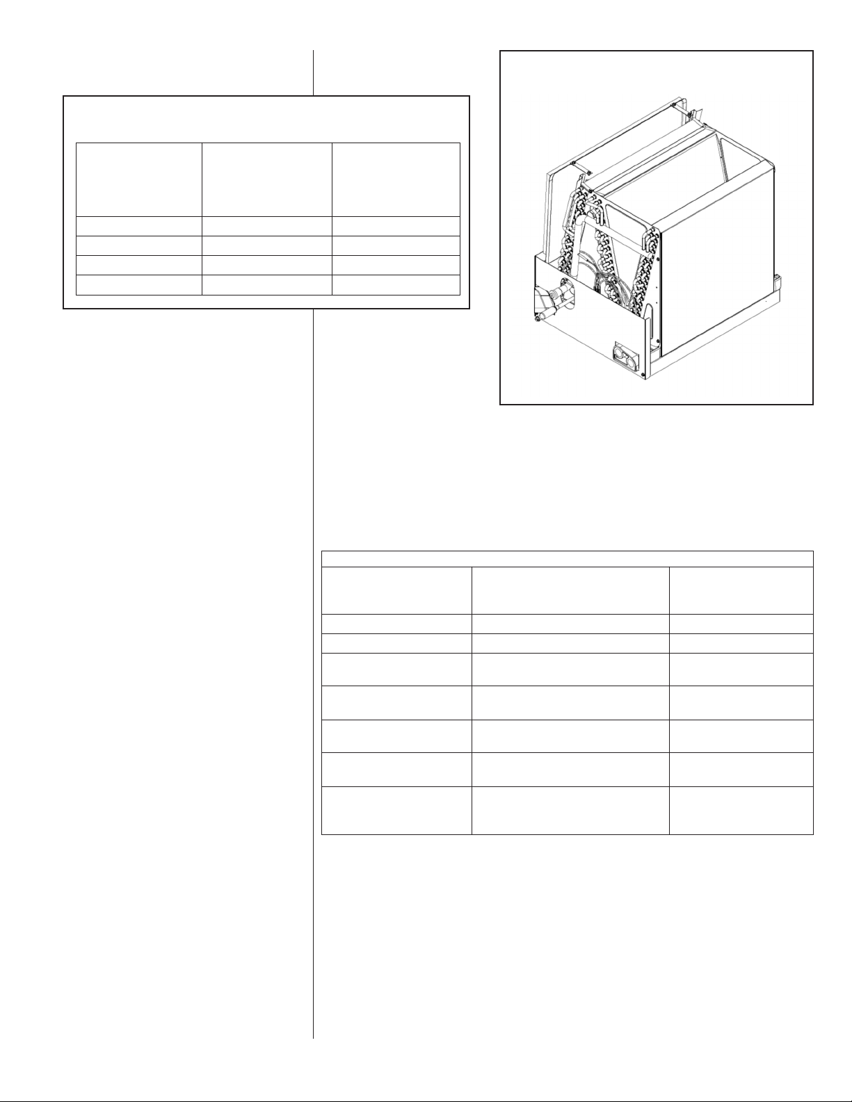
TABLE 5
UNCASED COIL ADAPTER KIT
Uncased Coil
Adapter Uncased
Model A Coil
Number Model
RXBA Width In. (-)CF
B14x20 13.1 **14
17x20 16.6 **17
B
B21x20 20.1 **21
B24x20 23.6 **24
FIGURE 20
NCASED COIL ADAPTER KIT ASSEMBLED
U
NOTE: Sliding the coil into the coil rail before attaching coil rack front.
5.5 R-22 TXV CONVERSION KITS
To be used to convert R-410A coil to operate with R-22
FURNACE COIL CROSS REFERENCE CHART
ORIGINAL COIL ALUMINUM TUBE CONVERSION KIT
(-)CFA-**2414 (-)CF2414STA RXCT-HBA
(-)CFA-**2417 (-)CF2417STA RXCT-HBA
(-)CFA-**3617
(-)CFA-**3621
(-)CFA-**4821 (-)CF4821STA or
(-)CFA-**4824
(-)CFA-**6024 (-)CF4824HTA,
**= AU, HM, OR HU
(-)CF3617STA, (-)CF2417MTA, or
(-)CF3621STA, (-)CF2421MTA, or
RECOMMENDED R-22 TXV
REPLACEMENT COIL MODEL NO.
(-)CF2417HTA/(-)CF3621H
(-)CF2421HTA/(-)CF3621H
(-)CF3621MTA/(-)CF4821M RXCT-HBC
(-)CF4824STA
or (-)CF3624MTA/(-)CF4821M
(-)CF6024STA, (-)CF6024HTA,
or (-)CF3624HTA/(-)CF6021S
RXCT-HBB
RXCT-HBB
RXCT-HBC
RXCT-HBD
21
Page 22

222324 CM 0516
Page 23

Page 24

 Loading...