

Page 1
92-101691-05-02
SUPERSEDES 92-101691-05-01
AIR-COOLED CONDENSING UNITS
(-)ASL-JEC 18 SEER EQUIPPED WITH THE COMFORT CONTROL
2
SYSTEM™ AND FEATURING DUAL DRIVE COMPRESSORS IN
SELECT MODELS
INSTALLATION INSTRUCTIONS
[ ] INDICATES METRIC CONVERSIONS
ISO 9001:2000
Featuring Earth-Friendly
R-410A Refrigerant
Page 2

TABLE OF CONTENTS
1.0 SAFETY INFORMATION . . . . . . . . . . . . . . . . . . . . . . . . . . . . . . . . . . . . . . . . . . . . 3
2.0 GENERAL INFORMATION . . . . . . . . . . . . . . . . . . . . . . . . . . . . . . . . . . . . . . . . . . 5
2.1 Checking Product Received . . . . . . . . . . . . . . . . . . . . . . . . . . . . . . . . . . . . 5
2.2 Application . . . . . . . . . . . . . . . . . . . . . . . . . . . . . . . . . . . . . . . . . . . . . . . . . . 5
2.3 Dimensions . . . . . . . . . . . . . . . . . . . . . . . . . . . . . . . . . . . . . . . . . . . . . . . . . 6
2
.4 Electrical and Physical Data . . . . . . . . . . . . . . . . . . . . . . . . . . . . . . . . . . . . 6
2.5 Proper Installation . . . . . . . . . . . . . . . . . . . . . . . . . . . . . . . . . . . . . . . . . . . . 7
3.0 LOCATING UNIT . . . . . . . . . . . . . . . . . . . . . . . . . . . . . . . . . . . . . . . . . . . . . . . . . . 7
3.1 Corrosive Environment . . . . . . . . . . . . . . . . . . . . . . . . . . . . . . . . . . . . . . . . 7
3.2 Condenser Location. . . . . . . . . . . . . . . . . . . . . . . . . . . . . . . . . . . . . . . . . . . 7
3.3 Operational Issues. . . . . . . . . . . . . . . . . . . . . . . . . . . . . . . . . . . . . . . . . . . . 8
3.4 For Condensers With Space Limitations . . . . . . . . . . . . . . . . . . . . . . . . . . . 8
3.5 Customer Satisfaction Issues . . . . . . . . . . . . . . . . . . . . . . . . . . . . . . . . . . . 8
3.6 Unit Mounting. . . . . . . . . . . . . . . . . . . . . . . . . . . . . . . . . . . . . . . . . . . . . . . . 8
3
.7 Factory-Preferred Tie-Down Method . . . . . . . . . . . . . . . . . . . . . . . . . . . . . . 8
4.0 REFRIGERANT CONNECTIONS . . . . . . . . . . . . . . . . . . . . . . . . . . . . . . . . . . . . . 9
4.1 Tools Required for Installing & Servicing R-410A Models . . . . . . . . . . . . . . 9
4.2 Specifications of R-410A . . . . . . . . . . . . . . . . . . . . . . . . . . . . . . . . . . . . . . 10
4.3 Quick Reference Guide for R-410-A . . . . . . . . . . . . . . . . . . . . . . . . . . . . . 10
5.0 REPLACEMENT UNITS. . . . . . . . . . . . . . . . . . . . . . . . . . . . . . . . . . . . . . . . . . . . 11
6.0 INDOOR COIL . . . . . . . . . . . . . . . . . . . . . . . . . . . . . . . . . . . . . . . . . . . . . . . . . . . 11
6.1 Location . . . . . . . . . . . . . . . . . . . . . . . . . . . . . . . . . . . . . . . . . . . . . . . . . . . 11
7.0 INTERCONNECTING TUBING . . . . . . . . . . . . . . . . . . . . . . . . . . . . . . . . . . . . . . 11
7.1 Vapor and Liquid Lines . . . . . . . . . . . . . . . . . . . . . . . . . . . . . . . . . . . . . . . 11
7.2 Maximum Length of Lines . . . . . . . . . . . . . . . . . . . . . . . . . . . . . . . . . . . . . 12
7.3 Outdoor Unit Installed Above or Below Indoor Coil . . . . . . . . . . . . . . . . . . 12
7.4 Tubing Installation . . . . . . . . . . . . . . . . . . . . . . . . . . . . . . . . . . . . . . . . . . . 12
7.5 Tubing Connections. . . . . . . . . . . . . . . . . . . . . . . . . . . . . . . . . . . . . . . . . . 15
7.6 Leak Testing . . . . . . . . . . . . . . . . . . . . . . . . . . . . . . . . . . . . . . . . . . . . . . . 15
8.0 DUAL DRIVE COMPRESSORS. . . . . . . . . . . . . . . . . . . . . . . . . . . . . . . . . . . . . . 16
8.1 Compressor Identification . . . . . . . . . . . . . . . . . . . . . . . . . . . . . . . . . . . . . 16
8.2 Comfort Control
2
System™ Control Identification . . . . . . . . . . . . . . . . . . . 16
8.3 Comfort Control
2
System™ Control Operation . . . . . . . . . . . . . . . . . . . . . 17
9.0 COMPRESSOR CRANKCASE HEAT (CCH) . . . . . . . . . . . . . . . . . . . . . . . . . . . 17
10.0 HARD START COMPONENTS . . . . . . . . . . . . . . . . . . . . . . . . . . . . . . . . . . . . . . 17
11.0 HIGH AND LOW PRESSURE CONTROLS (HPC AND LPC). . . . . . . . . . . . . . . 17
11.1 Evacuation Procedure . . . . . . . . . . . . . . . . . . . . . . . . . . . . . . . . . . . . . . . . 18
12.0 CONDENSING UNITS EQUIPPED WITH THE COMFORT CONTROL
2
SYSTEM™ . . . . . . . . . . . . . . . . . . . . . . . . . . . . . . . . . . . . . . . . . . . . . . . . . . . . . . 18
12.1 Control Description . . . . . . . . . . . . . . . . . . . . . . . . . . . . . . . . . . . . . . . . . . 18
12.2 Comfort Control
2
Control Wiring . . . . . . . . . . . . . . . . . . . . . . . . . . . . . . . . 20
12.3 Comfort Control
2
Diagnostic Codes in Dual Drive . . . . . . . . . . . . . . . . . . . 20
12.4 Comfort Control
2
ICC Control Operation . . . . . . . . . . . . . . . . . . . . . . . . . . 21
12.5 Active Compressor Protection Mode . . . . . . . . . . . . . . . . . . . . . . . . . . . . . 22
12.6 Test and Fault Recall Modes . . . . . . . . . . . . . . . . . . . . . . . . . . . . . . . . . . . 23
12.7 ICC Diagnostic Codes . . . . . . . . . . . . . . . . . . . . . . . . . . . . . . . . . . . . . . . . 25
12.8 Conventional 24VAC Thermostat Control Wiring . . . . . . . . . . . . . . . . . . . 28
12.9 Typical Non-Communicating Thermostat Wiring Diagrams. . . . . . . . . . . . 29
12.10 Diagnostic Codes in Dual Drive Condensing Units With Conventional
Thermostat Wiring . . . . . . . . . . . . . . . . . . . . . . . . . . . . . . . . . . . . . . . . . . . 30
12.11 ICC Control Operation with Conventional Thermostat Wiring . . . . . . . . . . 30
12.12 Active Compressor Protection Mode . . . . . . . . . . . . . . . . . . . . . . . . . . . . . 31
12.13 Test and Fault Recall Modes . . . . . . . . . . . . . . . . . . . . . . . . . . . . . . . . . . . 33
13.0 ELECTRICAL WIRING. . . . . . . . . . . . . . . . . . . . . . . . . . . . . . . . . . . . . . . . . . . . . 34
13.1 Power Wiring . . . . . . . . . . . . . . . . . . . . . . . . . . . . . . . . . . . . . . . . . . . . . . . 34
13.2 Grounding . . . . . . . . . . . . . . . . . . . . . . . . . . . . . . . . . . . . . . . . . . . . . . . . . 34
13.3 Control Wiring . . . . . . . . . . . . . . . . . . . . . . . . . . . . . . . . . . . . . . . . . . . . . . 34
14.0 START-UP AND PERFORMANCE . . . . . . . . . . . . . . . . . . . . . . . . . . . . . . . . . . . 35
15.0 CHECKING AIRFLOW. . . . . . . . . . . . . . . . . . . . . . . . . . . . . . . . . . . . . . . . . . . . . 35
16.0 CHECKING REFRIGERANT CHARGE . . . . . . . . . . . . . . . . . . . . . . . . . . . . . . . . 35
16.1 Charging Units With R-410A Refrigerant. . . . . . . . . . . . . . . . . . . . . . . . . . 36
16.2 Charging By Liquid Pressure . . . . . . . . . . . . . . . . . . . . . . . . . . . . . . . . . . . 36
16.3 Charging By Weight. . . . . . . . . . . . . . . . . . . . . . . . . . . . . . . . . . . . . . . . . . 36
16.4 Final Leak Testing . . . . . . . . . . . . . . . . . . . . . . . . . . . . . . . . . . . . . . . . . . . 36
17.0 ACCESSORIES . . . . . . . . . . . . . . . . . . . . . . . . . . . . . . . . . . . . . . . . . . . . . . . . . . 37
17.1 Remote Outdoor Temperature Model . . . . . . . . . . . . . . . . . . . . . . . . . . . . 37
18.0 TROUBLESHOOTING . . . . . . . . . . . . . . . . . . . . . . . . . . . . . . . . . . . . . . . . . . . . . 37
18.1 Comfort Control
2
System™ System Initial Startup . . . . . . . . . . . . . . . . . . 37
18.2 Replacement of Comfort Control
2
System™ Control Board . . . . . . . . . . . 38
18.3 Electrical Checks Flow Chart. . . . . . . . . . . . . . . . . . . . . . . . . . . . . . . . . . . 39
18.4 Cooling Mechanical Checks Flow Chart . . . . . . . . . . . . . . . . . . . . . . . . . . 40
18.5 General Trouble Shooting Chart . . . . . . . . . . . . . . . . . . . . . . . . . . . . . . . . 41
18.6 Service Analyzer Charts . . . . . . . . . . . . . . . . . . . . . . . . . . . . . . . . . . . . 42-46
18.7 Subcooling Calculation . . . . . . . . . . . . . . . . . . . . . . . . . . . . . . . . . . . . . . . 47
19.0 WIRING DIAGRAMS. . . . . . . . . . . . . . . . . . . . . . . . . . . . . . . . . . . . . . . . . . . . 48-49
2
Page 3
Continued on next page ➜
3
1.0 SAFETY INFORMATION
!
WARNING
THESE INSTRUCTIONS ARE INTENDED AS AN AID TO QUALIFIED, LICENSED
SERVICE PERSONNEL FOR PROPER INSTALLATION, ADJUSTMENT AND
OPERATION OF THIS UNIT. READ THESE INSTRUCTIONS THOROUGHLY
BEFORE ATTEMPTING INSTALLATION OR OPERATION. FAILURE TO FOLLOW THESE INSTRUCTIONS MAY RESULT IN IMPROPER INSTALLATION,
ADJUSTMENT, SERVICE OR MAINTENANCE POSSIBLY RESULTING IN FIRE,
ELECTRICAL SHOCK, PROPERTY DAMAGE, PERSONAL INJURY OR DEATH.
!
WARNING
THE MANUFACTURER’S WARRANTY DOES NOT COVER ANY DAMAGE OR
DEFECT TO THE AIR CONDITIONER CAUSED BY THE ATTACHMENT OR USE
OF ANY COMPONENTS, ACCESSORIES OR DEVICES (OTHER THAN THOSE
AUTHORIZED BY THE MANUFACTURER) INTO, ONTO OR IN CONJUNCTION
WITH THE AIR CONDITIONER. YOU SHOULD BE AWARE THAT THE USE OF
UNAUT HOR IZ ED CO MPO NENTS , A CC ESS ORIES OR DEV ICE S MAY
ADVERSELY AFFECT THE OPERATION OF THE AIR CONDITIONER AND MAY
ALSO ENDANGER LIFE AND PROPERTY. THE MANUFACTURER DISCLAIMS
ANY RESPONSIBILITY FOR SUCH LOSS OR INJURY RESULTING FROM THE
USE OF SUCH UNAUTHORIZED COMPONENTS, ACCESSORIES OR DEVICES.
!
WARNING
DISCONNECT ALL POWER TO UNIT BEFORE STARTING MAINTENANCE.
FAILURE TO DO SO CAN CA USE ELEC TRICAL SHO CK RESULTI NG IN
SEVERE PERSONAL INJURY OR DEATH.
!
WARNING
DO NOT USE OXYGEN TO PURGE LINES OR PRESSURIZE SYSTEM FOR
LEAK TE ST. OXYGEN REACTS VIOLEN TLY WITH OIL, WHICH CAN
CAUSE AN EXPLOSION RESULTING IN SEVERE PERSONAL INJURY OR
DEATH.
!
WARNING
THE UNIT MUST BE PERMANENTLY GROUNDED. FAILURE TO DO SO
CAN CAUSE ELECTRICAL SHOCK RESULTING IN SEVERE PERSONAL
INJURY OR DEATH.
!
WARNING
TURN OFF ELECTRIC POWER AT THE FUSE BOX OR SERVICE PANEL
BEFORE MAKING ANY ELECTRICAL CONNECTIONS.
ALSO, THE GROUND CONNECTION MUST BE COMPLETED BEFORE
MAKING LINE VOLTAGE CONNEC TIONS. FAILURE TO DO SO CAN
RESULT IN EL ECTRICAL SHOCK, SEVERE PERSONAL INJUR Y OR
DEATH.
Page 4
4
!
CAUTION
UNIT MAY START SUDDENLY AND WITHOUT WARNING
Solid red light indicates a thermostat call for unit operation is present at
the ICC control. ICC control will attempt to start unit after short cycle timer
expires or when in Active Protection mode will attempt to restart unit prior
to Lockout mode.
!
CAUTION
UNIT MAY START SUDDENLY AND WITHOUT WARNING
Solid red light indicates a thermostat call for unit operation is present at the
ICC. ICC will attempt to start unit after short cycle timer expires or when in
Active Protection mode will attempt to restart unit prior to Lockout mode.
!
CAUTION
THE TOP OF THE SCROLL COMPRESSOR SHELL IS HOT. TOUCHING THE
COMPRESSOR TOP MAY RESULT IN SERIOUS PERSONAL INJURY.
!
CAUTION
R-410A PRESSURES ARE APPROXIMATELY 60% HIGHER THAN R-22
PRESSURES. USE APPROPRIATE CARE WHEN USING THIS REFRIGERANT. FAILURE TO EXERCISE CARE MAY RESULT IN EQUIPMENT DAMAGE, OR PERSONAL INJURY.
!
CAUTION
THE COMPRESSOR HAS AN INTERNAL OVERLOAD PROTECTOR. UNDER
SOME CONDITIONS, IT CAN TAKE UP TO 2 HOURS FOR THIS OVERLOAD
TO RESET. MAKE SURE OVERLOAD HAS HAD TIME TO RESET BEFORE
CONDEMNING THE COMPRESSOR.
!
CAUTION
Only use evaporators approved for use on R-410A systems. Use of existing
R-22 evaporators can introduce mineral oil to the R-410A refrigerant forming two different liquids and decreasing oil return to the compressor. This
c
an result in compressor failure.
!
CAUTION
When coil is installed over a finished ceiling and/or living area, it is
rec ommen ded t hat a se con dar y she et me tal c ond ens ate p an be
constructed and installed under entire unit. Failure to do so can result
in property damage.
!
CAUTION
R-410A systems operate at higher pressures than R-22 systems. Do not use
R-22 service equipment or components on R-410A equipment.
Page 5

2.0 GENERAL INFORMATION
The (-)ASL-series of condensing units are designed to operate using the Comfort
Control
2
System™ or traditional 24VAC controls. These units are equipped with the
Comfort Control
2
. Your installation must have these components to use Comfort
Control
2
System™ :
• (-)ASL condensing unit equipped with the Comfort Control
2
System™
•
An air handler or furnace equipped with the Comfort Control
2
S
ystem™
• A Comfort Control
2
thermostat
If your installation does not meet the above requirements, you must use traditional
24VAC controls.
This installation instruction manual contains complete instructions for installation
and setup using Comfort Control
2
or conventional 24VAC controls. Please refer to
the Engineering Specification Sheets for complete performance data, thermostat,
and accessory listings.
The information contained in this manual has been prepared to assist in the proper
installation, operation and maintenance of the air conditioning system. Improper
installation, or installation not made in accordance with these instructions, can
result in unsatisfactory operation and/or dangerous conditions (noise and component failure), and can cause the related warranty not to apply.
Read this manual and any instructions packaged with separate equipment required
to make up the system prior to installation. Retain this manual for future reference.
To achieve optimum efficiency and capacity, the indoor cooling coils listed in the
condensing unit specification sheet should be used.
2.1 CHECKING PRODUCT RECEIVED
Upon receiving unit, inspect it for any shipping damage. Claims for damage, either
apparent or concealed, should be filed immediately with the shipping company.
Check condensing unit model number, electrical characteristics and accessories to
determine if they are correct. Check system components (evaporator coil, condensing unit, evaporator blower, etc.) to make sure they are properly matched.
2.2 APPLICATION
Before specifying any air conditioning equipment, a survey of the structure and a
heat gain calculation must be made. A heat gain calculation begins by measuring
all external surfaces and openings that gain heat from the surrounding air and
quantifying that heat gain. A heat gain calculation also calculates the extra heat
load caused by sunlight and by humidity removal.
Air conditioning systems are sized on the cooling load calculation. There are two
capacities that enable the equipment to provide comfort. The first is sensible capacity.
Sensible heat is the heat energy measured on the dry bulb thermometer as it is
added or removed.
The second form of heat is called latent or hidden heat. This is heat held in the
humidity in the air.
A properly-sized unit removes both forms of heat, producing a comfortable living
space. An oversized system cycles on and off too quickly and does not properly
remove humidity, producing an uncomfortable living space. Select the indoor and
outdoor equipment combination based on the manufacturer’s engineering data.
After the equipment combination has been selected, satisfying both sensible and
latent conditioning requirements, the system must be properly installed. Only then
can the unit provide the comfort the manufacturer intends.
There are several factors that the installers must consider:
• Outdoor unit location • Proper equipment evacuation
• System refrigerant charge • Indoor unit airflow
• Indoor unit blower speed • Supply and return air duct design and sizing
• System air balancing • Diffuser and return air grille location and sizing
!
WARNING
TH E MANUFACTU RE R’ S W AR RANTY DOES NOT COVER ANY
DA MAGE OR D EFECT TO THE
AIR CONDITIONER CAUSED BY
THE ATTACHMENT OR USE OF
ANY CO MPO NEN TS. ACC ESS
ORIES OR DEVICE S (OTHER
THAN THOSE AUTHORIZED BY
THE MANUF ACTUR ER ) IN TO,
ONT O OR I N CON JUNCT ION
WI TH THE AIR COND IT IONER.
YOU SHOULD BE AWARE THAT
THE USE OF UN AUTHO RIZ ED
COMPONENTS, ACCESSORIES
OR DEVICES MAY ADVERSELY
AFF ECT TH E OP ERA TIO N
OF THE AIR CONDITIONER AND
MAY AL SO E NDA NGER L IFE
AND PROPERTY. THE MANUFACTUR ER DIS CLAIM S ANY
RES PONSI BIL ITY FOR SUC H
LO SS OR I NJ UR Y RESULTING
FRO M THE USE OF SU CH
UNAUTHORIZED COMPONENTS,
ACCESSORIES OR DEVICES.
MATCH ALL COMPONENTS:
• OUTDOOR UNIT
• INDOOR COIL/METERING DEVICE
• INDOOR AIR HANDLER/FURNACE
• REFRIGERANT LINES
5
Page 6
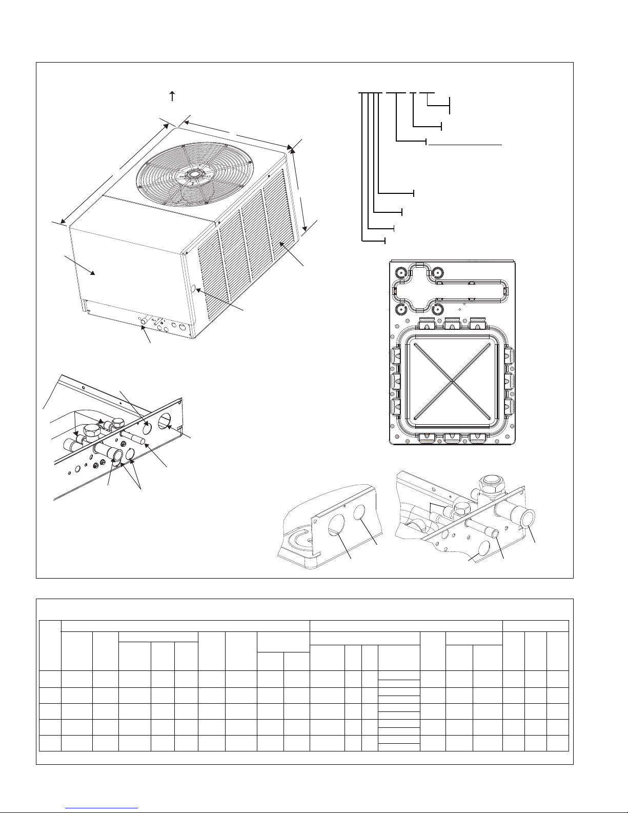
FIGURE 1
DIMENSIONS AND INSTALLATION CLEARANCES
UNIT MODEL NUMBER EXPLANATION
(-)ASL – 036 JEC
E
C = EQUIPPED WITH THE
COMFORT CONTROL
2
SYSTEM™
J
- 208/230-1-60
(
NOMINAL CAPACITY)
024 = 24000 BTU/HR
036 = 36000 BTU/HR
039 = 39000 BTU/HR
048 = 48000 BTU/HR
060 = 60000 BTU/HR
L = DESIGN SERIES (R-410A)
S = 18 SEER
A = REMOTE CONDENSING UNIT
TRADE NAME
A
IR INLETS
(
LOUVERS)
A
LLOW 120 [305 mm]
MIN. CLEARANCE
3 SIDES
AIR DISCHARGE
ALLOW 600 [1524 mm] CLEARANCE
ALLOW 240 [610 mm]
ACCESS CLEARANCE
ACCESS
PANEL
L
W
H
ALTERNATE HIGH VOLTAGE
CONNECTION (KNOCKOUT)
1
1
1
/320[34 mm]
SERVICE
FITTINGS
LOW VOLTAGE
CONNECTION
7
/8"
[22 mm]
HIGH VOLTAGE
CONNECTION
1
11
/32" [34 mm]
LIQUID LINE
CONNECTION
SERVICE ACCESS
TO ELECTRICAL &
VALVES ALLOW
24" [610 mm]
CLEARANCE
ONE SIDE
2
7
/8" [73 mm] DIA.
ACCESSORY
KNOCKOUTS
VAPOR LINE
CONNECTION
A-00002
BASE PAN
ALLOW 24" [610 mm]
ACCESS CLEARANCE
ALTERNATE LINE VOLTAGE
ENTRY (KNOCKOUT)
1
1
1
⁄32" [34 MM]
CONNECT THE LINE
VOLTAGE CONDUIT TO
THE BOTTOM OF THE
CONTROL BOX
AIR INLETS
(LOUVERS)
ALLOW 6” [152 mm]
MIN. CLEARANCE
3
SIDES
ACCESS
PANEL
AIR DISCHARGE
ALLOW 60" [1524 mm] CLEARANCE
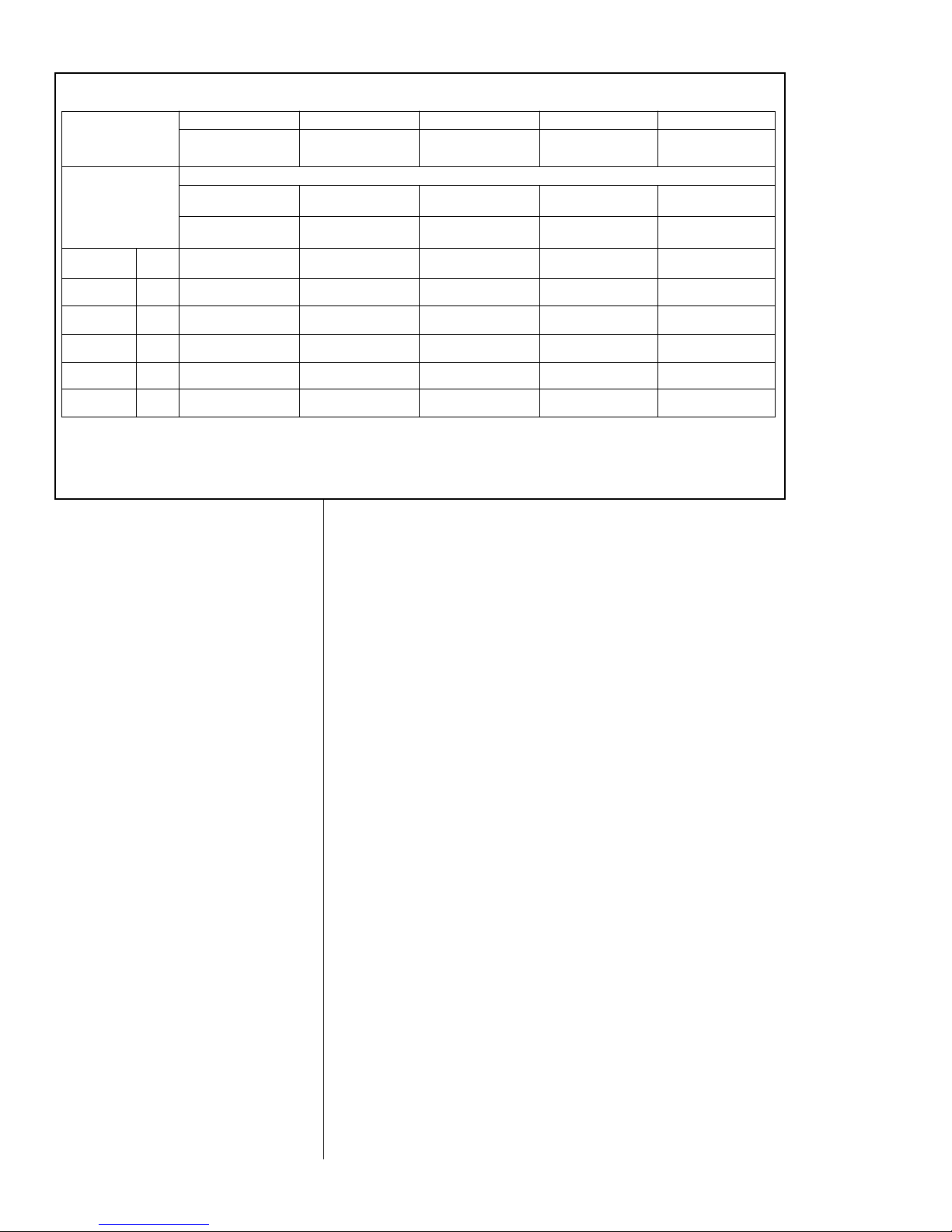
TABLE 1
(-)ASL-JEC ELECTRICAL DATA
Model
Number
(-)ASL
Phase
Frequency
(Hz)
Voltage
(Volts)
Compressor
Fan
Motor
Full
Load
Amperes
(FLA)
Minimum
Circuit
Ampacity
Amperes
Fuse or HACR
Circuit Breaker
Outdoor Coil Weight
Minimum
Amperes
Maximum
Amperes
Face Area
Sq. Ft. [m
2
]
No.
Rows
Fins
Per
Inch
CFM [L/s}
R-410a
Oz. [g]
Net Lbs.
[kg]
Shipping
Lbs. [kg]
Height
“H”
(Inches)
Length
“L”
(Inches)
Width
“W”
(Inches)
ELECTRICAL PHYSICAL DIMENSIONAL DATA
Voltage
Operating
Range
(Volts)
No.
Compressors
Rated
Load
Amperes
(RLA)
Locked
Rotor
Amperes
(LRA)
024JEC 1-60-208/230 197-253 1 10.3/10.3 52 0.5 14/14 20/20 20/20 15.8 [1.47] 1 20 HS* 3400 [1605] 144 [4082] 236 [107] 256 [116.2] 33 44 3/8 31 1/2
LS* 2800 [1322]
036JEC 1-60-208/230 197-253 1 16.7/16.7 82 2.8 24/24 30/30 40/40 23.0 [2.14] 1 22 HS* 3400 [1605] 155 [4394] 251 [113.9] 261 [118.4] 33 44 3/8 31 1/2
LS* 2800 [1322]
039JEC 1-60-208/230 188-253 2 17.9/17.9 96 2.8 26/26 30/30 40/40 23.0 [2.14] 2 20 HS* 3500 [1651] 268 [7598] 326 [147.9] 336 [152.4] 33 44 3/8 31 1/2
LS* 2800 [1322]
048JEC 1-60-208/230 188-253 2 26.9/26.9 117 2.8 37/37 45/45 60/60 23.0 [2.14] 2 20 HS* 3500 [1651] 253 [7172] 326 [147.9] 336 [152.4] 33 44 3/8 31 1/2
LS* 2800 [1322]
060JEC 1-60-208/230 188-253 2 28.2/28.2 146 2.8 39/39 50/50 60/60 23.0 [2.14] 2 20 HS* 3500 [1651] 241 [6832] 328 [148.8] 338 [153.3] 33 44 3/8 31 1/2
LS* 2800 [1322]
*HS = high speed
*LS = low speed
BOTTOM VIEW SHOWING DRAIN OPENINGS
(\\\\\ SHADED AREAS).
LINE VOLTAGE ENTRY
1
11
⁄32" [34 MM]
CONNECT THE LINE
VOLTAGE CONDUIT TO
THE BOTTOM OF THE
CONTROL BOX
2.3 DIMENSIONS
2.4 ELECTRICAL & PHYSICAL DATA
6
LINE VOLTAGE
ENTRY
7
⁄8" [22 MM]
SERVICE ACCESS
FOR 024 & 036 MODELS
SERVICE ACCESS
FOR 039, 048 & 060 MODELS
LOW LINE
VOLTAGE7⁄8"
LOW LINE
VOLTAGE
7
⁄8"
VAPOR LINE
CONNECTION
LIQUID LINE
CONNECTION
SERVICE
FITTING
HIGH LINE
VOLTAGE 1
1
⁄4"
Page 7
2.5 PROPER INSTALLATION
Proper sizing and installation of this equipment is critical to achieve optimal performance. Use the information in this Installation Instruction Manual and reference the
applicable Engineering Specification Sheet when installing this product.
IMPORTANT: This product has been designed and manufactured to meet ENERG
Y STAR
®
c
riteria for energy efficiency when matched with appropriate coil components. However, proper refrigerant charge and proper airflow are critical to achieve
rated capacity and efficiency. Installation of this product should follow the manufacturer’s refrigerant charging and airflow instructions. Failure to confirm proper
charge and airflow may reduce energy efficiency and shorten equipment life.
3.0 LOCATING UNIT
3.1 Corrosive Environment
The metal parts of this unit may be subject to rust or deterioration if exposed to a
corrosive environment. This oxidation could shorten the equipment’s useful life.
Corrosive elements include, but are not limited to, salt spray, fog or mist in seacoast
areas, sulphur or chlorine from lawn watering systems, and various chemical contaminants from industries such as paper mills and petroleum refineries.
If the unit is to be installed in an area where contaminants are likely to be a problem, special attention should be given to the equipment location and exposure.
• Avoid having lawn sprinkler heads spray directly on the unit cabinet.
• In coastal areas, locate the unit on the side of the building away from the water-
front.
• Shielding provided by a fence or shrubs may give some protection, but cannot
violate minimum airflow and service access clearances.
• Elevating the unit off its slab or base enough to allow air circulation will help
avoid holding water against the basepan.
Regular maintenance will reduce the build-up of contaminants and help to protect
the unit’s finish.
• Frequent washing of the cabinet, fan blade and coil with fresh water will remove
most of the salt or other contaminants that build up on the unit.
• Regular cleaning and waxing of the cabinet with a good automobile polish will
provide some protection.
• A good liquid cleaner may be used several times a year to remove matter that
will not wash off with water.
Several different types of protective coatings are offered in some areas. These
coatings may provide some benefit, but the effectiveness of such coating materials
cannot be verified by the equipment manufacturer.
3.2 CONDENSER LOCATION
Consult local and national building codes and ordinances for special installation
requirements. Following location information will provide longer life and simplified
servicing of the outdoor condenser.
NOTE: These units must be installed outdoors. No ductwork can be attached, or
other modifications made, to the discharge grille. Modifications will affect performance or operation.
!
WARNING
DIS CONNE CT A LL P OWE R TO U NIT B EFO RE STA RTI NG
MAINTENANCE. FAILURE TO DO SO CAN CAUSE ELECTRICAL SHOCK
RESULTING IN SEVERE PERSONAL INJURY OR DEATH.
7
Page 8

3.3 Operational Issues
• IMPORTANT: Locate the unit in a manner that will not prevent, impair or compromise the performance of other equipment horizontally installed in proximity
to the unit. Maintain all required minimum distances to gas and electric meters,
d
ryer vents, exhaust and inlet openings. In the absence of National Codes, or
manufacturers’ recommendations, local code recommendations and requirements will take precedence.
• Refrigerant piping and wiring should be properly sized and kept as short as
possible to avoid capacity losses and increased operating costs.
• Locate the unit where water run off will not create a problem with the equipment. Position the unit away from the drip edge of the roof whenever possible.
Units are weatherized, but can be affected by the following:
o Water pouring into the unit from the junction of rooflines, without protective
guttering. Large volumes of water entering the heat pump while in operation
can impact fan blade or motor life, and coil damage may occur to a heat
pump if moisture cannot drain from the unit under freezing conditions.
o Freezing moisture, or sleeting conditions, can cause the cabinet to ice-over
prematurely and prevent heat pump operation, requiring backup heat, which
generally results in less economical operation.
• Closely follow clearance recommendations on Page 6.
o 24” to the service panel access
o 60” above heat pump fan discharge (unit top) to prevent recirculation
o 6” to heat pump coil grille air inlets
3.4 For Units With Space Limitations
FOR CONDENSERS WITH SPACE LIMITATIONS
In the event that a space limitation exists, we will permit the following clearances:
Single Unit Applications: Clearances below 6 inches will reduce unit capacity and
efficiency. Do not reduce the 60-inch discharge, or the 24-inch service clearances.
Multiple Unit Applications: When multiple condenser grille sides are aligned, a 6inch per unit clearance is recommended, for a total of 12” between two units. Two
combined clearances below 12 inches will reduce capacity and efficiency. Do not
reduce the 60-inch discharge, or 24-inch service, clearances.
3.5 Customer Satisfaction Issues
• The condensing unit should be located away from the living, sleeping and
recreational spaces of the owner and those spaces on adjoining property.
• To prevent noise transmission, the mounting pad for the outdoor unit should not
be connected to the structure, and should be located sufficient distance above
grade to prevent ground water from entering the unit.
3.6 Unit Mounting
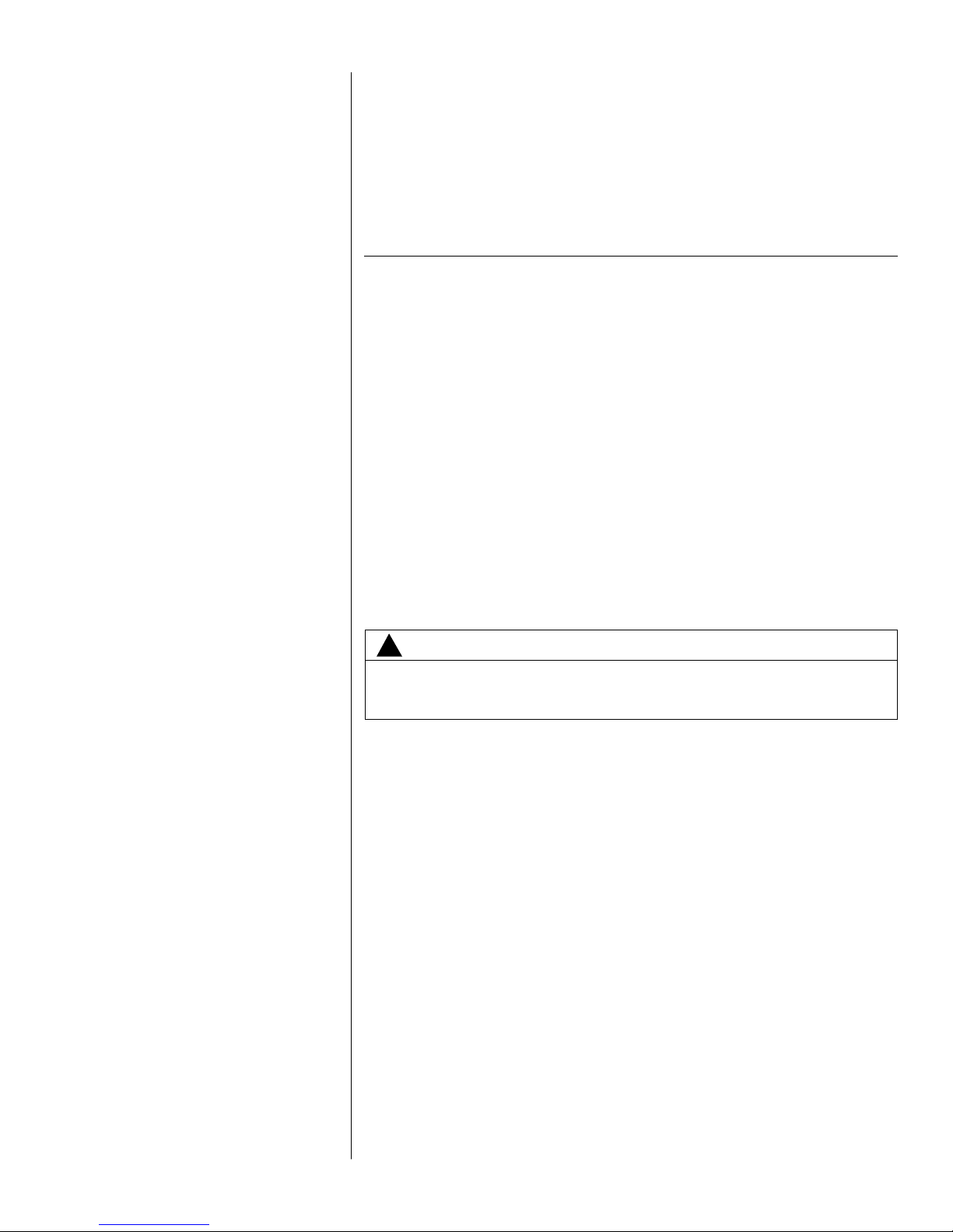
If elevating the condensing unit, either on a flat roof or on a slab, observe the
following guidelines.
• The base pan provided elevates the heat pump 3/4” above the base pad.
• If elevating a unit on a flat roof, use 4” x 4” (or equivalent) stringers positioned
to distribute unit weight evenly and prevent noise and vibration (see Figure 2).
NOTE: Do not block drain openings shown in Figure 1.
3.7 Factory-Preferred Tie-Down Method
INSTRUCTIONS
IMPORTANT: These instructions are intended as a guide to securing equipment for
wind-load ratings of “120 MPH sustained wind load” and “3-second, 150 MPH gust.”
While this procedure is not mandatory, the Manufacturer does recommend that
equipment be properly secured in areas where high wind damage may occur.
STEP 1: Before installing, clear pad of any dirt or debris.
IMPORTANT: The pad must be constructed of industry-approved materials,
and must be thick enough to accommodate the concrete fastener.
STEP 2: Center base pan on pad, ensuring it is level.
8
Page 9
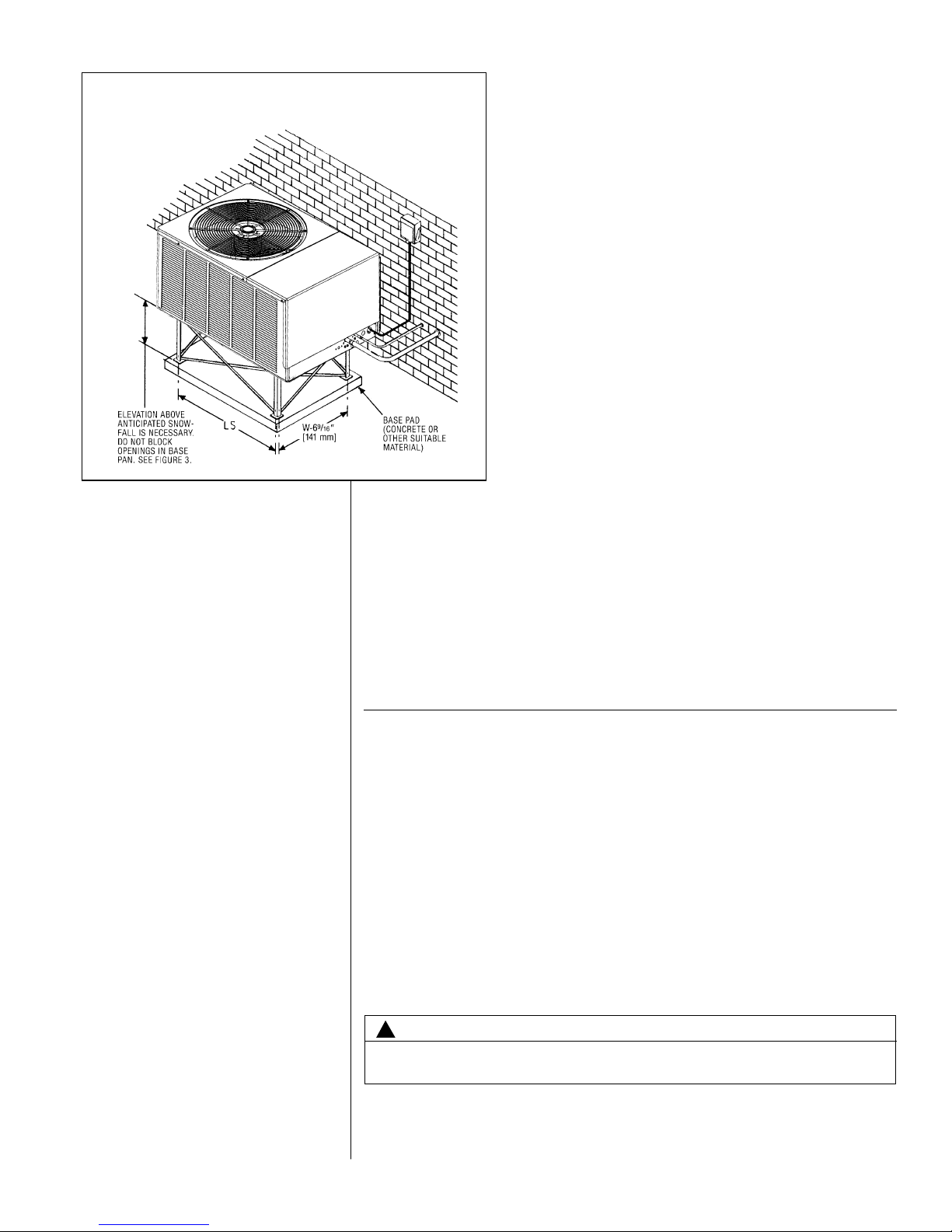
STEP 3: Using basepad as a guide, mark spots on concrete where 4 holes will be
drilled (see Figure 3).
STEP 4: Drill four pilot holes in pad, ensuring that the hole is at least 1/4” deeper
than the concrete screw being used.
STEP 5: Center basepan over pre-drilled holes and insert concrete screws.
STEP 6: Tighten concrete screws.
NOTE: Do not over-tighten the concrete screws. Doing so can weaken the
integrity of the concrete screw and cause it to break.
STEP 7: Finish unit assembly per unit’s installation instructions.
4.0 REFRIGERANT CONNECTIONS
All units are factory charged with Refrigerant 410A. All models are supplied with
service valves. Keep tube ends sealed until connection is to be made to prevent
system contamination.
4.1 Tools Required For Installing & Servicing R-410A Models
Manifold Sets:
-Up to 800 PSIG High side
-Up to 250 PSIG Low Side
-550 PSIG Low Side Retard
Manifold Hoses:
-Service Pressure Rating of 800 PSIG
Recovery Cylinders:
-400 PSIG Pressure Rating
-Dept. of Transportation 4BA400 or BW400
9
!
CAUTION
R-410A systems operate at higher pressures than R-22 systems. Do not use
R-22 service equipment or components on R-410A equipment.
FIGURE 2
R
ECOMMENDED ELEVATED INSTALLATION
Page 10
4.2 Specifications of R-410A:
Application: R-410A is not a drop-in replacement for R-22; equipment designs
must accommodate its higher pressures. It cannot be retrofitted into R-22 heat
pumps.
Physical Properties: R-410A has an atmospheric boiling point of -62.9°F and its
saturation pressure at 77°F is 224.5 psig.
Composition: R-410A is an azeotropic mixture of 50% by weight difluoromethane
(HFC-32) and 50% by weight pentafluoroethane (HFC-125).
Pressure: The pressure of R-410A is approximately 60% (1.6 times) greater
than R-22. Recovery and recycle equipment, pumps, hoses and the like need to
have design pressure ratings appropriate for R-410A. Manifold sets need to range
up to 800 psig high-side and 250 psig low-side with a 550 psig low-side retard.
Hoses need to have a service pressure rating of 800 psig. Recovery cylinders need
to have a 400 psig service pressure rating. DOT 4BA400 or DOT BW400.
Combustibility: At pressures above 1 atmosphere, mixture of R-410A and air can
become combustible. R-410A and air should never be mixed in tanks or supply
lines, or be allowed to accumulate in storage tanks. Leak checking should
never be done with a mixture of R-410A and air. Leak checking can be per-
formed safely with nitrogen or a mixture of R-410A and nitrogen.
4.3 Quick Reference Guide For R-410A
• R-410A refrigerant operates at approximately 60% higher pressure (1.6 times)
than R-22. Ensure that servicing equipment is designed to operate with R-410A.
• R-410A refrigerant cylinders are pink in color.
• R-410A, as with other HFC’s is only compatible with POE oils.
10
FIGURE 3
S
CREW LOCATIONS
TABLE 2
DIMENSIONS
MODEL NUMBER LWABCD
(-)ASL-024/036/039/048/060 41.5 29.813 15 38 3.5 26.5
Page 11
• Vacuum pumps will not remove moisture from oil.
• R-410A systems are to be charged with liquid refrigerants. Prior to March 1999,
R-410A refrigerant cylinders had a dip tube. These cylinders should be kept
upright for equipment charging. Post March 1999 cylinders do not have a dip
tube and should be inverted to ensure liquid charging of the equipment.
• Do not install a suction line filter drier in the liquid line.
• A liquid line filter drier is standard on every unit. Only manufacturer approved liquid line filter driers can be used. These are Sporlan (CW083S) and Alco
(80K083S) driers. These filter driers are rated for minimum working pressure of
600 psig.
• Desiccant (drying agent) must be compatible for POE oils and R-410A.
5.0 REPLACEMENT UNITS
To prevent failure of a new condensing unit, the existing evaporator tubing system
must be correctly sized and cleaned or replaced. Care must be exercised that the
expansion device is not plugged. For new and replacement units, a liquid line filter
drier should be installed and refrigerant tubing should be properly sized. Test the oil
for acid. If positive, a suction line filter drier is mandatory.
IMPORTANT: WHEN REPLACING AN R-22 UNIT WITH AN R-410A UNIT,
EITHER REPLACE THE LINE SET OR ENSURE THAT THE EXISTING LINE SET
IS THOROUGHLY CLEANED OF ANY OLD OIL OR DEBRIS.
6.0 INDOOR COIL
REFER TO INDOOR COIL MANUFACTURER’S INSTALLATION INSTRUCTIONS.
IMPORTANT: The manufacturer is not responsible for the performance and opera-
tion of a mismatched system, or for a match listed with another manufacturer’s coil.
NOTE: All (-)ASL units must be installed with a TXV Evaporator.
The thermostatic expansion valve is specifically designed to operate with R-410A.
DO NOT use an R-22 TXV or evaporator. The existing evaporator must be
replaced with the factory specified TXV evaporator specifically designed for
R-410A.
6.1 Location
Do not install the indoor coil in the return duct system of a gas or oil furnace.
Provide a service inlet to the coil for inspection and cleaning. Keep the coil pitched
toward the drain connection.
7.0 INTERCONNECTING TUBING
7.1 Vapor and Liquid Lines
Keep all lines sealed until connection is made.
Make connections at the indoor coil first.
11
!
CAUTION
Only use evaporators approved for use on R-410A systems. Use of existing R-22
evaporators can introduce mineral oil to the R-410A refrigerant forming two different liquids and decreasing oil return to the compressor. This can result in compressor failure.
!
CAUTION
When coil i s in stall ed o ver a finis hed cei ling and/ or l ivi ng a rea, it is
rec ommen ded t hat a s eco ndary s hee t met al co ndensate p an be
construct ed an d i nstalled under enti re un it. Failure to do so can result
in property damage.
Page 12
12
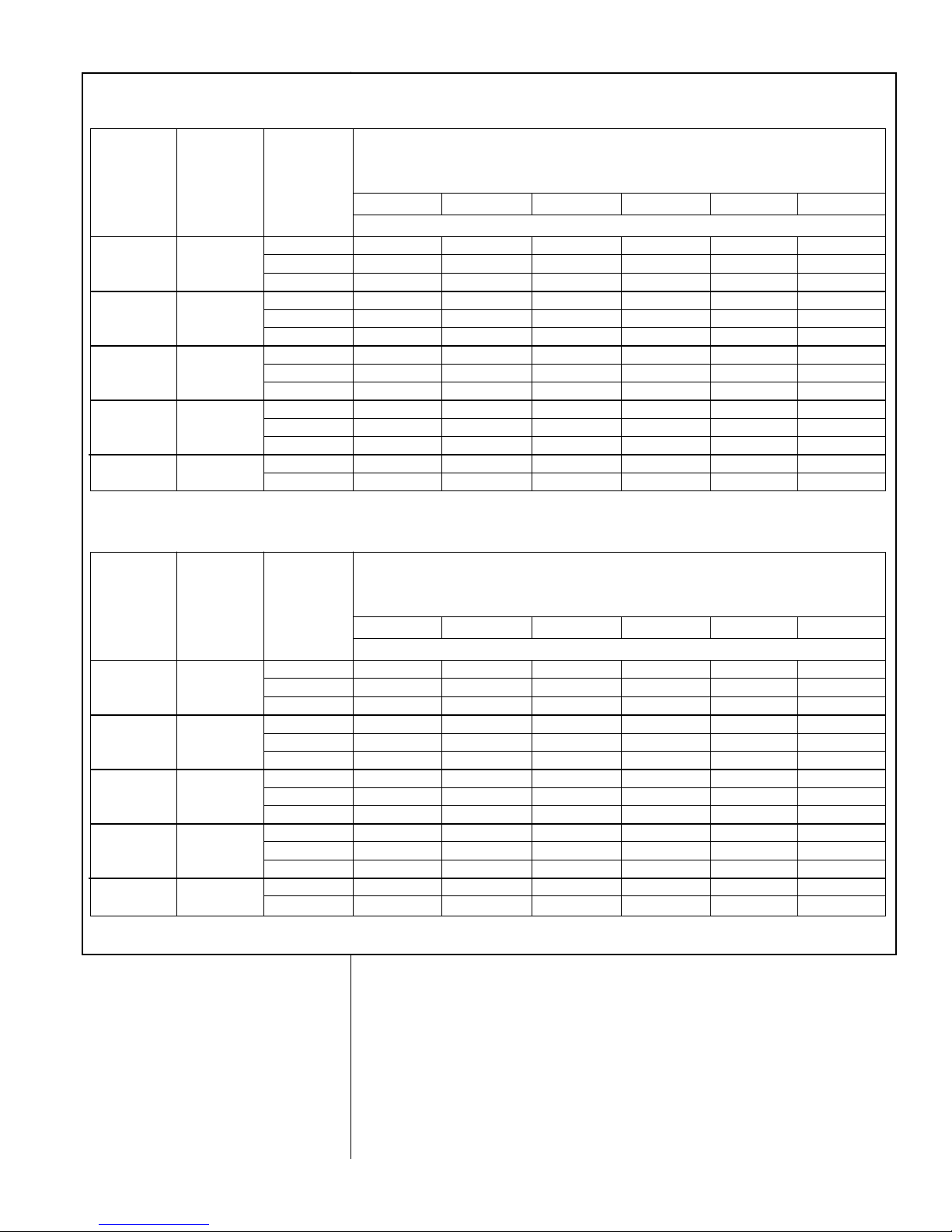
Refer to Line Size Information in Tables 3, 4, 5 and 6 for correct size and multipliers
to be used to determine capacity for various vapor line diameters and lengths of run.
The losses due to the lines being exposed to outdoor conditions are not included.
The factory refrigeration charge in the outdoor unit is sufficient for 15 feet of interconnecting lines. The factory refrigeration charge in the outdoor unit is sufficient for
the unit and 15 feet of standard size interconnecting liquid and vapor lines. For different lengths, adjust the charge as indicated below.
1/4” ± .3 oz. per foot
5/16” ± .4 oz. per foot
3/8” ± .6 oz. per foot
1/2” ± 1.2 oz. per foot
7.2 Maximum Length of Lines
The maximum length of interconnecting line is 150 feet. Always use the shortest
length possible with a minimum number of bends. Additional compressor oil is not
required for any length up to 150 feet.
NOTE: Excessively long refrigerant lines cause loss of equipment capacity.
7.3 Outdoor Unit Installed Above or Below Indoor Coil
Use the following guidelines when installing the unit:
1. Expansion Valve Coil:
a. The vertical separation cannot exceed the value in Tables 4, 5, and 6.
b. No changes are required for expansion valve coils.
2. It is recommended to use the smallest liquid line size permitted to minimize the
system charge.
3. Tables 4, 5, and 6 may be used for sizing horizontal runs.
7.4 Tubing Installation
Observe the following when installing correctly sized type “L” refrigerant tubing
between the condensing unit and evaporator coil:
• If a portion of the liquid line passes through a hot area where liquid refrigerant
can be heated to form vapor, insulating the liquid line is required.
• Use clean, dehydrated, sealed refrigeration grade tubing.
• Always keep tubing sealed until tubing is in place and connections are to be
made.
TABLE 3
VAPOR LINE CAPACITY MULTIPLIER
024
(-)ASL
Unit Vapor Line
Connection Size
(inches I.D.) [mm]
Vapor Line Run
Feet [m]
3/4” [19.05] I.D.
Sweat
7/8” [22.23] I.D.
Sweat
7/8” [22.23] I.D.
Sweat
7/8” [22.23] I.D.
Sweat
7/8” [22.23] I.D.
Sweat
5/8” [15.88]
Optional
5/8” [15.88]
Optional
5/8” [15.88]
Optional
5/8” [15.88]
Optional
3/4” [19.05]
Optional
25‘ [7.62]
50’ [15.24]
75’ [22.86]
100’ [30.48]
125’ [38.10]
150’ [45.72]
Opt.
Std.
Opt.
Std.
Opt.
Std.
Opt.
Std.
Opt.
Std.
Opt.
Std.
3/4” [19.05]
Standard
3/4” [19.05]
Standard
3/4” [19.05]
Standard
3/4” [19.05]
Standard
7/8” [22.23]
Standard
1.00 0.99 0.99 0.98 0.99
1.00 1.00 1.00 1.00 1.00
0.98 0.98 0.97 0.96 0.98
1.00 1.00 0.99 0.99 0.99
0.98 0.96 0.96 0.94 0.96
1.00 0.99 0.99 0.98 0.99
0.98 0.95 0.95 0.92 0.95
N/A N/A N/A N/A N/A
0.96 0.94 0.93 0.90 0.94
N/A N/A N/A N/A N/A
0.96 0.92 0.91 0.88 0.93
N/A N/A N/A N/A N/A
036 039 048 060
Vapor Line Diameter (inches O.D.) [mm]
NOTES:
1. Do NOT exceed the limits in the liquid and suction line sizing charts.
2. Do NOT use 7/8 OD suction lines in 2 or 4-ton applications.
3. Do NOT use 1-1/8 OD suction line in ANY application.
4. Line sets over 75 feet MUST use the optional suction line.
Page 13
13
• Blow out the liquid and vapor lines with dry nitrogen before connecting to the
outdoor unit and indoor coil. Any debris in the line set will end up plugging the
expansion device.
• As an added precaution, a high quality filter drier is standard on R-410A units.
• Do not allow the vapor line and liquid line to be in contact with each other. This
causes an undesirable heat transfer resulting in capacity loss and increased
power consumption. The vapor line must be insulated.
• If tubing has been cut, make sure ends are deburred while holding in a position
to prevent chips from falling into tubing. Burrs such as those caused by tubing
cutters can affect performance dramatically, particularly on small liquid line
sizes.
L
IQUID LINE SIZE - OUTDOOR UNIT ABOVE INDOOR COIL
R-410A
System
Capacity
Model
Line Size
Connection
Size (Inch
I.D.) [mm]
Line Size
(Inch O.D.)
[mm]
Minimum Vertical Separation - Feet [m]
1/4” [6.35]* 0010 [3.05] 34 [10.36] 58 [17.68] 82 [24.99]
-024 3/8” [9.53] 5/16” [7.93] 000000
3/8” [9.52] 000000
5/16” [7.93] 006 [1.83] 14 [4.27] 21 [6.40] 28 [8.53]
-036 3/8” [9.53] 3/8” [9.52]* 00 0000
1/2” [12.70] 00 0000
5/16” [7.93]* 000010 [3.05] 24 [7.32]
-039 3/8” [9.53] 3/8” [9.52] 00 0000
1/2” [12.70] 00 0000
5/16” [7.93]* 00018 [5.49] 40 [12.19] 62 [18.90]
-048 3/8” [9.53]
3/8” [9.52] 000000
1/2” [12.70] 00 0000
-060 3/8” [9.53]
3/8” [9.52]* 000000
1/2” [12.70] 00 0000
25 [7.62] 50 [15.24] 75 [22.86] 100 [30.48] 125 [38.1] 150 [45.72]
Liquid Line Size
Outdoor Unit Above Indoor Coil (Cooling Only - Does not apply to Heat Pumps)
Total Equivalent Length - Feet [m]
L
IQUID LINE SIZE - OUTDOOR UNIT BELOW INDOOR COIL
R-410A
System
Capacity
Model
Line Size
Connection
Size (Inch
I.D.) [mm]
Line Size
(Inch O.D.)
[mm]
Maximum Vertical Separation - Feet [m]
1/4” [6.35]* 25 [11.28] 13 [3.96] N/A N/A N/A N/A
-024 3/8” [9.53] 5/16” [7.93] 25 [14.33] 44 [13.41] 40 [12.19] 36 [10.97] 30 [9.14] 24 [7.32]
3/8” [9.52] 25 [15.24] 48 [14.63] 47 [14.33] 46 [14.02] 45 [13.72] 43 [13.11]
5/16” [7.93] N/A N/A N/A N/A N/A N/A
-036 3/8” [9.53] 3/8” [9.52]* 12 [3.66] 9 [2.74] N/A N/A N/A N/A
1/2” [12.70] 14 [4.27] 13 [3.96] 13 [3.96] 12 [3.66] 12 [3.66] 11 [3.35]
5/16” [7.93]* 15 [4.57] 11 [3.35] N/A N/A N/A N/A
-039 3/8” [9.53] 3/8” [9.52] 18 [5.49] 17 [5.18] 15 [4.57] 13 [3.96] 12 [3.66] 10 [3.05]
1/2” [12.70] 20 [6.10] 19 [5.79] 19 [5.79] 19 [5.79] 18 [5.49] 18 [5.49]
5/16” [7.93]* 25 [10.36] 24 [7.32] N/A N/A N/A N/A
-048 3/8” [9.53] 3/8” [9.52] 25 [11.89] 36 [10.97] 34 [10.36] 32 [9.75] 29 [8.84] 23 [7.01]
1/2” [12.70] 25 [12.50] 40 [12.19] 40 [12.19] 39 [11.89] 39 [11.89] 38 [11.58]
3/8” [9.52]* 25 [11.28] 33 [10.06] 30 [9.14] 25 [7.62] 15 [4.57] N/A
-060 3/8” [9.53]
1/2” [12.70] 25 [11.89] 39 [11.89] 38 [11.58] 37 [11.28] 37 [11.28] 36 [10.97]
25 [7.62] 50 [15.24] 75 [22.86] 100 [30.48] 125 [38.1] 150 [45.72]
Liquid Line Size
Outdoor Unit Below Indoor Coil (Cooling Only - Does not apply to Heat Pumps)
Total Equivalent Length - Feet [m]
TABLE 4
(-)ASL LIQUID LINE SIZING
NOTES: N/A = Application Not Recommended
*Standard Line Size
NOTES: N/A = Application Not Recommended
*Standard Line Size
Page 14
14
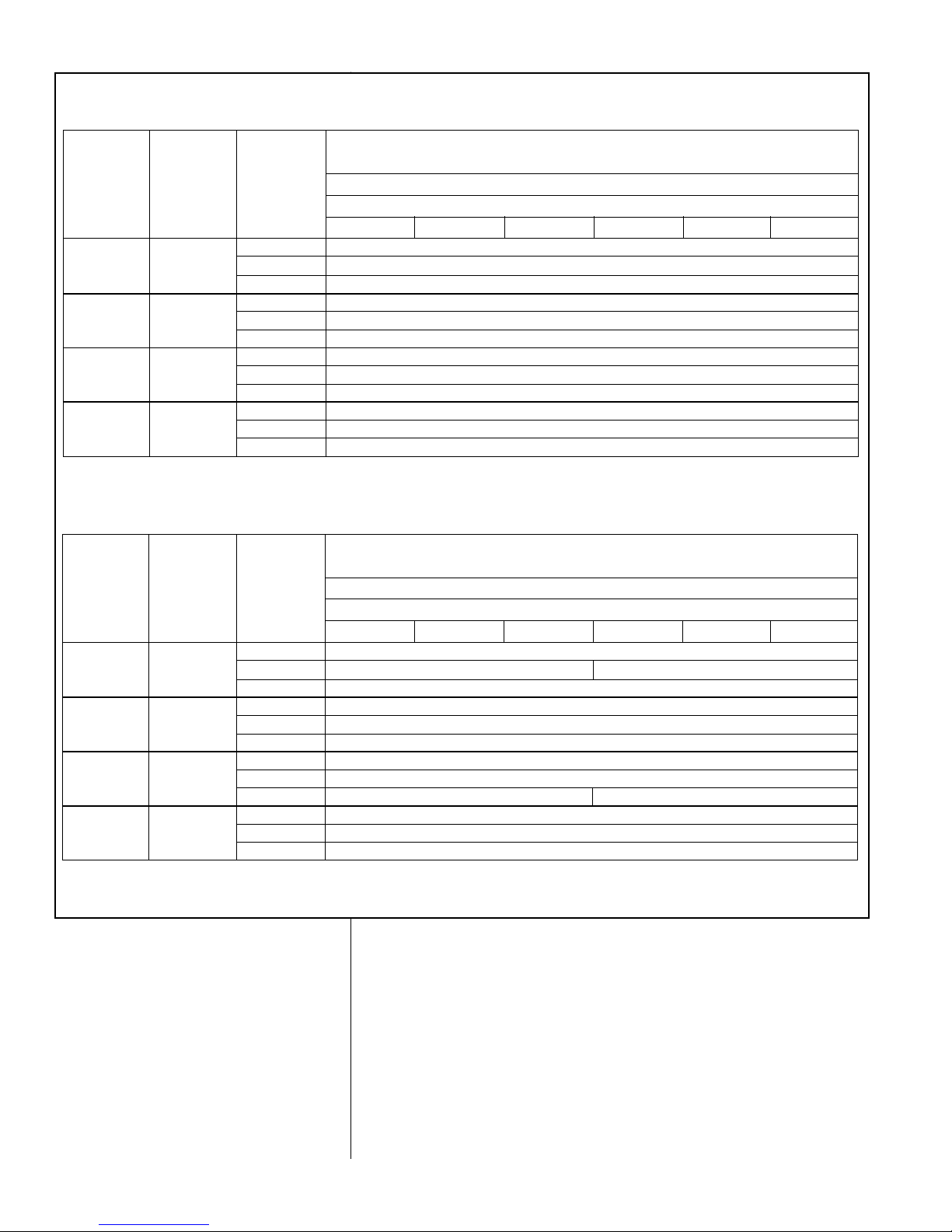
T
ABLE 5
(
-)ASL SUCTION LINE SIZING
SUCTION LINE SIZE - OUTDOOR UNIT ABOVE INDOOR COIL
R-410A
System
Capacity
Model
Line Size
Connection
Size (Inch
I.D.) [mm]
Line Size
(Inch O.D.)
[mm]
Outdoor Unit ABOVE Indoor Coil (Cooling Only - Does not apply to Heat Pumps)
Total Equivalent Length - Feet [m]
5/8” [15.88] Same as Liquid Line Size Table
-024 3/4” [19.05] 3/4” [19.05]* NA
7/8” [22.23] NA
5/8” [15.88] Same as Liquid Line Size Table
-036 & -039 3/4” [19.05] 3/4” [19.05]* NA
7/8” [22.23] NA
5/8” [15.88] Same as Liquid Line Size Table
-048 7/8” [22.22] 3/4” [19.05] Same as Liquid Line Size Table
7/8” [22.23]* NA
3/4” [19.05] Same as Liquid Line Size Table
-060 7/8” [22.22] 7/8” [22.23]* NA
1-1/8” [28.58] NA
25 [7.62] 50 [15.24] 75 [22.86] 100 [30.48] 125 [38.1] 150 [45.72]
Suction Line Size
S
UCTION LINE SIZE - OUTDOOR UNIT BELOW INDOOR COIL
R-410A
System
Capacity
Model
Line Size
Connection
Size
(Inch I.D.)
[mm]
Line Size
(Inch O.D.)
[mm]
Outdoor Unit BELOW Indoor Coil (Cooling Only - Does not apply to Heat Pumps)
Total Equivalent Length - Feet [m]
5/8” [15.88] Same as Liquid Line Size Table
-024 3/4” [19.05] 3/4” [19.05]* Same as Liquid Line Size Table NA
7/8” [22.23] NA
5/8” [15.88] Same as Liquid Line Size Table
-036 & -039 3/4” [19.05] 3/4” [19.05]* Same as Liquid Line Size Table
7/8” [22.23] NA
5/8” [15.88] Same as Liquid Line Size Table
-048 7/8” [22.22] 3/4” [19.05] Same as Liquid Line Size Table
7/8” [22.23]* Same as Liquid Line Size Table NA
3/4” [19.05] Same as Liquid Line Size Table
-060 7/8” [22.22] 7/8” [22.23]* Same as Liquid Line Size Table
1-1/8” [28.58] NA
25 [7.62] 50 [15.24] 75 [22.86] 100 [30.48] 125 [38.1] 150 [45.72]
Suction Line Size
NOTES: Using suction line larger than shown in chart will result in poor oil return.
N/A = Application Not Recommended
*Standard Line Size
NOTES: Using suction line larger than shown in chart will result in poor oil return.
N/A = Application Not Recommended
*Standard Line Size
Page 15
15
• For best operation, keep tubing run as short as possible with a minimum number of elbows or bends.
• Locations where the tubing will be exposed to mechanical damage should be
a
voided. If it is necessary to use such locations, the copper tubing should be
housed to prevent damage.
• If tubing is to be run underground, it must be run in a sealed watertight chase.
•
Use care in routing tubing and do not kink or twist. Use a good tubing bender
on the vapor line to prevent kinking.
• Route the tubing using temporary hangers, then straighten the tubing and
install permanent hangers. Line must be adequately supported.
• The vapor line must be insulated to prevent dripping (sweating) and prevent
performance losses. Armaflex and Rubatex are satisfactory insulations for this
purpose. Use 1/2” minimum insulation thickness, additional insulation may be
required for long runs.
• Check Table 3 for the correct vapor line size. Check Table 4 for the correct liquid line size.
7.5 Tubing Connections
Indoor coils have only a holding charge of dry nitrogen. Keep all tube ends sealed
until connections are to be made.
• Use type “L” copper refrigeration tubing. Braze the connections with the following alloys:
– copper to copper - 5%
– Silver alloy (no flux)
– copper to steel or brass - 35%
– silver alloy (with flux)
• Be certain both refrigerant shutoff valves at the outdoor unit are closed.
• Clean the inside of the fittings and outside of the tubing with steel wool or sand
cloth before soldering. Always keep chips, steel wool, dirt, etc., out of the inside
when cleaning.
• Assemble tubing part way into fitting. Apply flux all around the outside of the
tubing and push tubing into stop. This procedure will keep the flux from getting
inside the system.
• Remove the cap and schrader core from service port to protect seals from heat
damage.
• Use an appropriate heatsink material around the copper stub and the service
valves before applying heat.
• IMPORTANT: Do not braze any fitting with the TEV sensing bulb attached.
• Braze the tubing between the outdoor unit and indoor coil. Flow dry nitrogen
into a service port and through the tubing while brazing.
• After brazing – use an appropriate heatsink material to cool the joint and
remove any flux residue.
• The service valves are not backseating valves. To open the valves, remove the
valve cap with an adjustable wrench. Insert a 3/16” or 5/16” hex wrench into the
stem. Back out counterclockwise.
• Replace the valve cap finger tight then tighten an additional 1/2 hex flat for a
metal-to-metal seal.
7.6 Leak Testing
• Pressurize line set and coil through service fittings with dry nitrogen to 150
PSIG maximum. Leak test all joints using liquid detergent. If a leak is found,
recover pressure and repair.
!
WARNING
DO NOT USE OXYGEN TO PURGE LINES OR PRESSURIZE SYSTEM FOR
LEAK TE ST. OXYGEN REACTS VIOLEN TLY WITH OIL, WHICH CAN
CAUSE AN EXPLOSION RESULTING IN SEVERE PERSONAL INJURY OR
DEATH.
Page 16
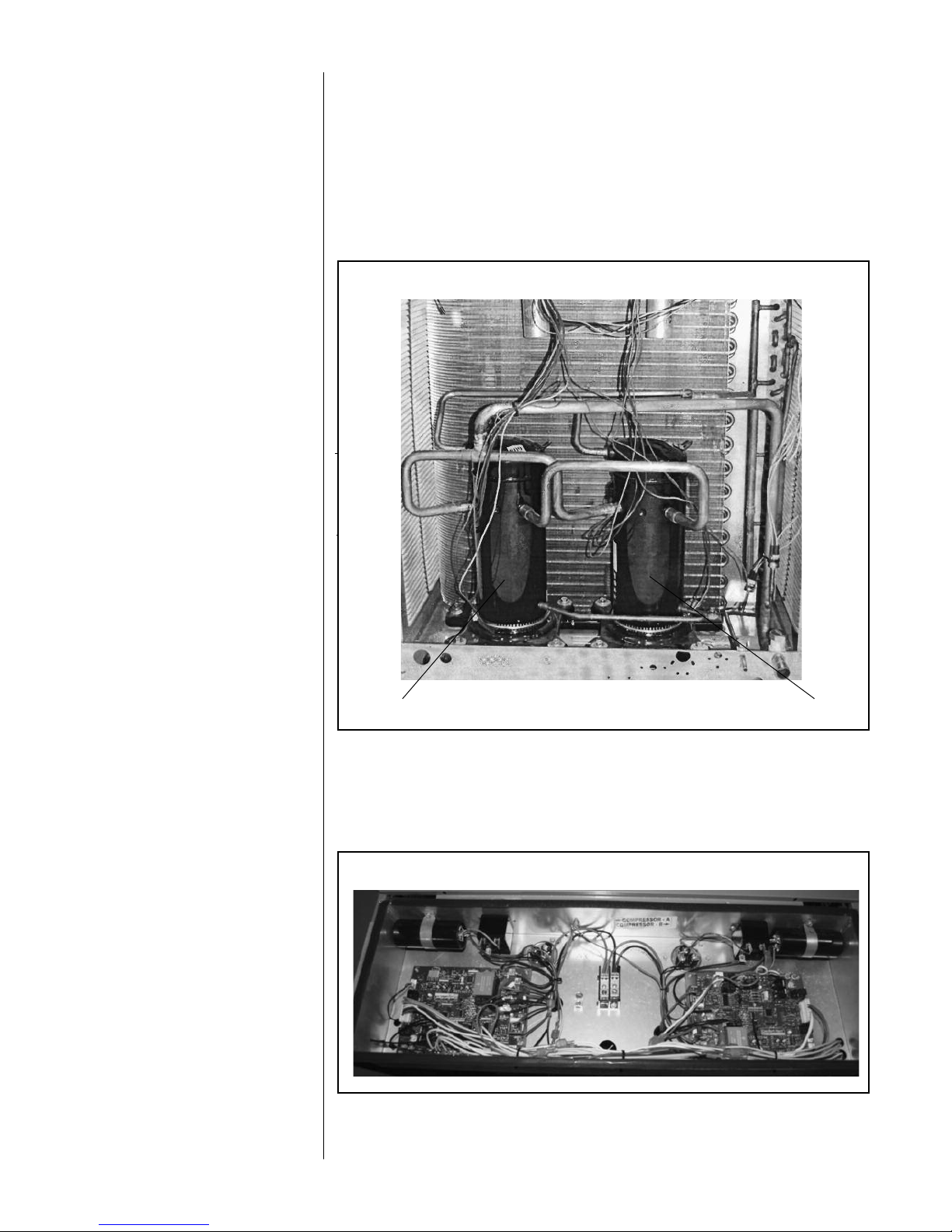
8.0 DUAL DRIVE COMPRESSORS
The -039, -048, & -060 condensing units contain two compressors to deliver maximum efficiency and comfort. The Dual Drive Compressors are sized to increase run
times at first stage operation (partial capacity). When additional capacity is needed,
a two stage thermostat energizes both compressors to deliver full rated capacity.
8.1 Compressor Identification
The individual compressors are identified as Compressor A and Compressor B.
When facing the access panel, Compressor A is on the left and Compressor B is on
the right. (See Figure 4.)
8.2 Comfort Control2System™ Control Identification
The Dual Drive condensing units use one (1) serial communicating control per compressor. There is a label in the control box that identifies each control/compressor
combination. When facing the access panel, Compressor A is controlled by the lefthand board and Compressor B is controlled by the right-hand board.
16
FIGURE 5
FIGURE 4
DUAL DRIVE COMPRESSORS
COMPRESSOR A COMPRESSOR B
Page 17

8.3 Comfort Control2System™ Control Operation
A Dual Drive unit has two controls instead of a single control. A Dual Drive control is
the same as any residential communicating control. Therefore, the features such as
fault recall and the operation of the test button are the same as any JEC control.
The two controls are identical and interchangeable. This allows the controls to be
swapped for troubleshooting if one of the controls is suspected of being defective.
Only one of the controls can be connected to a communicating network. The control
that is connected to the communications network is the primary control. It is located
on the left hand side when facing the unit. The primary control puts out a 24 VAC
signal to the secondary control when second stage is called for.
Each control will have a separate history of faults (up to 6) which can be accessed
b
y pressing the “Test” and “SW2” buttons. Only the primary control fault history can
be accessed by a service tool or the thermostat.
As with any JEC unit, the airflow will be automatically optimized when the system is
used in communicating mode. If a conventional thermostat is used with the system,
the dipswitches in the air handler must be set to provide the correct airflow.
9.0 COMPRESSOR CRANKCASE HEAT (CCH)
CCH is standard on these models due to refrigerant migration during the off cycle
that can result in a noisy start up.
Crankcase Heater Operation:
Supplemental Crankcase heat is required to prevent refrigerant migration in systems with relatively high system refrigerant charges. Each Dual Drive compressor
has its own crankcase heater.
The crankcase heater control is integrated into the Comfort Control
2
System™ and
is designed for maximum energy savings.
Summary of operation:
• The crankcase heater is off whenever the compressor is running.
• Once the compressor turns off, the crankcase heater control (CCH) begins the
two-hour timer countdown.
• If the compressor stays off for two hours, the CCH turns on the crankcase heater.
All heaters are located on the lower half of the compressor shell. Its purpose is to
drive refrigerant from the compressor shell during long off cycles, thus preventing
damage to the compressor during start-up.
At initial start-up or after extended shutdown periods, make sure the heater is energized for at least 12 hours before the compressor is started. (Disconnect switch on
and wall thermostat off.)
10.0 HARD START COMPONENTS
Factory-installed start components are standard on all models.
11.0 HIGH AND LOW PRESSURE CONTROLS
10.0 (HPC AND LPC)
These controls keep the compressor from operating in pressure ranges which can
cause damage to the compressor. Both controls are in the low voltage control circuit.
High pressure control (HPC) is an automatic-reset which opens near 610 PSIG and
closes near 420 PSIG.
The low pressure control (LPC) is an automatic-reset which opens near 50 PSIG
and closes near 95 PSIG.
NOTE: HPC and LPC are monitored by the Comfort Control2System™. See
Section 12.0.
17
Page 18

11.1 Evacuation Procedure
Evacuation is the most important part of the entire service procedure. The life and
efficiency of the equipment is dependent upon the thoroughness exercised by the
s
erviceman when evacuating air and moisture from the system.
Air in the system causes high condensing temperatures and pressure, resulting in
increased power input and non-verifiable performance.
Moisture chemically reacts with the refrigerant and oil to form corrosive hydrofluoric
and hydrochloric acids. These attack motor windings and parts, causing breakdown.
After the system has been leak checked and proven sealed, connect the vacuum
pump and evacuate system to 500 microns. The vacuum pump must be connected
to both the high and low sides of the system through adequate connections. Use
the largest size connections available since restrictive service connections may lead
to false readings because of pressure drop through the fittings.
IMPORTANT: Compressors (especially scroll type) should never be used to evacuate the air conditioning system because internal electrical arcing may result in a
damaged or failed compressor.
With thermostat in the “Off” position, turn the power on to the furnace and the heat
pump. Start the heat pump and the furnace with the thermostat. Make sure the
blower is operating.
12.0 CONDENSING UNITS EQUIPPED WITH THE
11.0 COMFORT CONTROL
2
SYSTEM™
Comfort Control2is the next generation of the Integrated Compressor Control (ICC)
and is an integral part of the Comfort Control
2
System™ with the following features:
12.1 Control Description (see Figure 4)
Dual 7-Segment LED
• Displays status and diagnostic codes (See Status and Diagnostic Description)
• Displays diagnostic/fault recall (See Test Mode/Fault Recall)
Red LED (Y1)
• Y1 red LED (solid on) indicates Y1 call from thermostat is present
Line Voltage Connector
• Line voltage is connected to control board at lug terminals L1 & L2
• Maximum wire size accepted is 6 AWG copper wire
• # 4 – 6 AWG 45 in/lbs
# 8 AWG 40 in/lbs
# 10 – 14 AWG 35 in/lbs
(Check wire terminations annually)
18
!
CAUTION
THE COMPRESSOR HAS AN INTERNAL OVERLOAD PROTECTOR. UNDER
SOME CONDITIONS, IT CAN TAKE UP TO 2 HOURS FOR THIS OVERLOAD
TO RESET. MAKE SURE OVERLOAD HAS HAD TIME TO RESET BEFORE
C
ONDEMNING THE COMPRESSOR.
!
CAUTION
UNIT MAY START SUDDENLY AND WITHOUT WARNING
Solid red light indicates a thermostat call for unit operation is present at
the ICC control. ICC control will attempt to start unit after short cycle timer
expires or when in Active Protection mode will attempt to restart unit prior
to Lockout mode.
COMFORT CONTROL
2
SYSTEM™ CONTROL WIRING
Page 19

Compressor Control (K2)
• Sealed single pole compressor relay switch with optical feedback feature (arc
detection)
Thermostat Connector (E2)
• R – 24VAC from the indoor unit 24VAC transformer (40 VA minimum)
• C – 24VAC Common from the indoor unit 24VAC transformer
• 1-Data: System Communications Line 1
• 2-Data: System Communications Line 2
Low Volt Fuse
• If required replace with 3 A automotive ATC style blade fuse
Low Pressure Control (LPC Input)
• Low-pressure control is factory installed
• Low pressure control is an automatic resetting device
High Pressure Control (HPC Input)
• High-pressure control is factory installed
• High pressure control is an automatic resetting device
Ambient Temperature Sensor (included with all applications)
• Included with all applications
TEST and SW2 Buttons
• TEST and SW2 buttons used to enter Test and Fault Recall Mode
Memory Card
• The memory card stores all unit information.
• The unit information is called shared data.
• The shared data is all the information needed for proper unit operation.
FIGURE 6
COMFORT CONTROL2BOARD
COMPRESSOR
WIRING
CONNECTOR
O.D. FAN (OFM) RELAY
COMPRESSOR
CONTROL (K2)
ICC (INTEGRATED
COMPRESSOR CONTROL)
TEST BUTTON
7-SEGMENT LED
AMBIENT DEFROST
CONTROL
DEFROST SENSOR
SW2 BUTTON
RED LED (Y1)
LOW VOLT FUSE
THERMOSTAT
CONNECTION (E2)
LOW PRESSURE CONTROL INPUT
HIGH PRESSURE CONTROL INPUT
{
MEMORY CARD
LINE VOLTAGE
CONNECTION
19
COMFORT CONTROL
2
SYSTEM™ CONTROL WIRING
Page 20

12.2 Comfort Control2System™ Control Wiring
An HVAC system equipped with Comfort Control2System™ consists of:
• Heat pump or condensing unit equipped with Comfort Control
2
• Air handler or furnace equipped with Comfort Control
2
• Comfort Control2thermostat
The four 18AWG low voltage control wires must be installed from the thermostat to
the indoor unit and from indoor unit to the outdoor unit. The wire length between the
thermostat and indoor unit should not be greater than 100 feet. The wire length
between the indoor unit and outdoor unit should not be greater than 125 feet.
IIMMPPOORRTTAANNTT::
If the installed system does not meet these requirements, the system must be wired using traditional control wiring, reference Section 12.7
Conventional 24VAC Thermostat Control Wiring.
Serial communications require four (4) control wires for unit operation:
R – 24VAC
C – 24VAC common
1 – Data wire 1
2 – Data wire 2
NNoottee::
Comfort Control2System™ requires 18 AWG thermostat wire.
NNoottee::
Term dipswitches should be in ON position.
If the low voltage control wiring is run in conduit with the power supply, Class I insulation is required. Class II insulation is required if run separate. Low voltage wiring
may be run through the insulated bushing provided in the 7/8 hole in the base
panel, up to and attached to the pigtails from the bottom of the control box. Conduit
can be run to the base panel if desired by removing the insulated bushing.
The serial communicating air handler or serial communicating furnace transformer
is equipped with a 24 volt, 50 VA transformer for proper system operation. See the
wiring diagram in Figure 5 for reference.
12.3 Comfort Control2System™ Diagnostic Codes in Dual Drive
12.3 Condensing Units
Comfort Control2System™ for compressor A is connected to the serial communicating network via Data Wire 1 and Data Wire 2. Each Comfort Control
2
System™
Control Board maintains separate fault history for the compressor it controls. Fault
codes for compressor A can be retrieved using a service tool or via the installer
menus. The fault codes for compressor B are accessible by two methods.:
1. Using a service tool plugged directly into the compressor B Comfort Control
2
board.
COMFORT CONTROL
2
SYSTEM™ CONTROL WIRING
20
FIGURE 7
TYPICAL COMFORT CONTROL2SYSTEM™ WIRING DIAGRAM
Indoor Unit
1
2
C
R
WIRING INFORMATION
Line Voltage
–Field Installed - - - - - –Factory Standard
1
2
R
C
1
2
R
C
Communicating Thermostat
Outdoor Unit
Page 21

SERIAL COMMUNICATIONS CONTROL WIRING
COMFORT CONTROL
2
SYSTEM™ CONTROL WIRING
2. Reading the codes directory off the dual 7-segment LEDs on the Comfort
Control
2
board of compressor B.
IMPORTANT: Fault codes for compressor B are NOT accessible via the serial comm
unicating network.
12.4 Comfort Control2ICC Control Operation
IInnssttaallllaattiioonn VVeerriiffii ccaattiioonn
• 24V AC power on R&C must be present at the ICC for it to operate
• Line voltage must be present at the ICC for the compressor and the outdoor fan
to operate
• The ICC displays a “0” for standby mode. Standby mode indicates line voltage
and 24VAC are present at the ICC and there is not a command for unit operation
from the serial communicating thermostat.
Zero (0) displayed
The unit is in standby
CCoommmmaanndd ffoorr CCoommpprreessssoorr OOppeerraattiioo nn ((YY11 LLEEDD))
• If a command for compressor operation is received by the ICC (first stage/second
stage cooling or first stage/second stage heating), the red Y1 LED will illuminate.
• The ICC has an on/off fan delay of one (1) second for each stage of heating or
cooling.
• The ICC ignores the low pressure control for the first 90 seconds of compressor
operation.
• The dual 7-segment LED displays five (5) operational status codes.
11)) FFiirrsstt SSttaaggee CCoooolliinngg OOppeerraattiioonn
– When the ICC receives a command for first
stage cooling operation, a lower case “c” is displayed on the dual 7-segment LEDs.
Lower case “c” indicates first stage cooling operation
22)) SSeeccoo nndd SSttaaggee CCoooo lliinngg OOppeerraattii oonn
– When the ICC receives a command for
second stage cooling operation, an upper case “C” is displayed on the dual 7segment LEDs.
Upper case “C” indicates second stage cooling operation
33--mmii nnuuttee AAnnttii--sshhoo rrtt CCyyccllee TTiimmeerr
• The ICC has a built in 3-minute time delay between compressor operations to
protect the compressor against short cycling. The dual 7-segment LEDs will flash
“c” or “C” while the short cycle timer is active and a command for unit operation is
received.
Flashing lower case c
A command for first stage cooling has been received
Flashing upper case C
A command for second stage cooling has been received
• The 3-minute time delay can be bypassed when a command for compressor
operation is present by pressing the TEST button for 1 second and releasing.
The compressor will begin operation and the dual 7-segment will stop flashing.
21
Figure X – Typical Serial Communication Wiring Diagram
Zero (0) displayed
The unit is in standby
Page 22

3300 SSeeccoonndd MMiinniimmuumm RRuunn TTii mmeerr
• The ICC has a built in 30 second minimum unit run time. If a command for compressor operation is received by the ICC and the command is removed, the compressor will continue to operate for 30 seconds. The dual 7-segment LEDs will
flash “c” or “C” while the minimum run timer is active.
11 SSeeccoonndd CCoommpprreess ssoorr//FFaann DDeellaayy
• The ICC starts/stops the outdoor fan one (1) second after the start/stop of the
compressor upon a command for compressor operation to minimize current
inrush and/or voltage drop.
12.5 Active Compressor Protection Mode
• The ICC actively protects the compressor from harmful operation during a fault
condition.
• When the ICC detects a condition that could damage the compressor, the ICC will
enter active protection mode and lockout compressor operation
• The condition causing active protection must be resolved then the ICC can be
reset to restart the system.
• There are five (5) active protection modes:
11)) LLooww PPrreessss uurree CCoonnttrrooll LLoocckkoo uutt
• The ICC will display a flashing “L” followed by a flashing 21 when a low pressure
control lockout occurs.
• The ICC addresses low pressure control faults differently depending on the mode
of unit operation (cooling or heating mode).
Active Protection – Code L21 – Open low pressure control
CCoooolliinngg MMooddee
• If the LPC opens three (3) times during the same command for cooling operation,
the ICC will lockout the compressor to keep it from continuing to operate and flash
a L” on the dual 7-segment LEDs followed by a “21”.
IIMMPPOORRTTAANNTT::
This mode of active protection must be manually reset.
22)) HHiigg hh PPrreessssuurree CCoonn ttrrooll LLoo cckkoouutt
• If the HPC opens three (3) times during the same command for unit operation, the
ICC will lockout the compressor to keep it from continuing to operate and flash a
L” on the dual 7-segment LEDs followed by a “29”.
Active Protection – Code L29 – Open high pressure control
IIMMPPOORRTTAANNTT::
This mode of active protection must be manually reset.
33)) LLoocckkeedd RRoottoo rr
• The ICC will display a flashing “L” followed by a flashing “04” when a locked rotor
condition occurs.
22
COMFORT CONTROL
2
SYSTEM™ CONTROL WIRING
Page 23

Active Protection – Code L4 – Locked rotor
If the ICC detects the compressor has run less than 15 seconds for four (4) consecutive starts during the same command for unit operation, the ICC will lockout
the compressor to keep it from continuing to operate and flash a “L” on the dual 7segment LEDs followed by a “04”.
IIMMPPOORRTTAANNTT::
This mode of active protection must be manually reset.
44)) CCoommpp rreessssoo rr PPrrootteecctt oorr TTrrii pp
• If ICC detects a protector trip it will display a “P”. If protector doesn’t reset within 4
hours, the ICC display will change to “5”.
Compressor Protector – Code P – Protector Trip
55)) OOppeenn SSttaarrtt CCiirrccuuiitt LL oocckkoouutt
• The ICC will display a flashing “L” followed by a flashing “06” when an open start
circuit condition occurs.
Active Protection – Code L6 – Compressor open start circuit
If the ICC detects current in the run circuit without current present in the start circuit, , the ICC will lockout the compressor to keep it from continuing to operate
and flash a “L” on the dual 7-segment LEDs followed by a “06”.
IIMMPPOORRTTAANNTT::
This mode of active protection must be manually reset.
66)) OOppeenn RRuunn CCiirrccuuiitt LLoocckkoouutt
• The ICC will display a flashing “L” followed by a flashing “07” when an open start
circuit condition occurs.
Active Protection – Code L7 – Compressor open run circuit
If the ICC detects current in the start circuit without current present in the run circuit, , the ICC will lockout the compressor to keep it from continuing to operate
and flash a “L” on the dual 7-segment LEDs followed by a “07”.
IIMMPPOORRTTAANNTT::
This mode of active protection must be manually reset.
EExxiittiinngg AAcc ttiivvee CCoo mmpprreessssoorr PPrrootteeccttii oonn LLoocc kkoouu tt
Three are three methods to reset the ICC after an active protection lockout:
1) Cycle the line voltage to the unit
2) Cycle 24VAC to the ICC (remove the R or C connection to the ICC)
3) Push the TEST button down with an insulated probe for one (1) second and
release
Note: The ICC will attempt to start the unit when the TEST button is pressed
and released
NNoottee::
The preferred method of resetting the ICC is to push the TEST button down
for one (1) second.
12.6 Test and Fault Recall Modes
TTeesstt MMoodd ee ((TTeesstt BBuuttttoonn oonn tthhee IICCCC))
• Enter TEST mode by pressing the TEST button with an insulated probe for one
(1) second and release.
23
COMFORT CONTROL
2
SYSTEM™ CONTROL WIRING
Lower case “d” indicates defrost operation (in heating mode)
3-minute Anti-short Cycle Timer
Page 24

24
• The TEST mode causes the ICC to do the following
1) Resets the ICC from any active protection lockout mode
2) Resets the 3-minute anti-short cycle timer
3) Energizes the unit without a command for unit operation
• If the 3-minute anti-short cycle timer or 30 second minimum run timer is active (a
flashing “c”, “C”, “h”, or “H” is displayed on the dual 7-segment LEDs) and a command for unit operation is present, TEST mode causes:
1) A “t” to display momentarily on the dual 7-segment display
Lower case “t”
2) The compressor will start and the outdoor fan will operate
3) The display will change to a steady “c” or “C” to show the current command for
unit operation.
Note: If a command for unit operation is present at the end of TEST mode will
cause the unit to continue to operate.
• If no command for unit operation is present, TEST mode causes
1) A steady “t” appears on the dual 7-segment LEDs
2) The compressor will start
3) The compressor will turn off after 5-seconds.
Note: Entering TEST mode without a command for unit operation will cause the
compressor to run 5-seconds.
FFaauulltt RReeccaallll MMooddee ((TTEESSTT aanndd SSWW22 BBuuttttoonnss))
• Enter
FFAAUULL TT RREECCAALLLL
mode by pressing the
TTEESSTT
and
SSWW22
buttons at the
same time with insulated probes for one (1) second and release.
• When entering and exiting FAULT RECALL mode the top and bottom segments
of the dual 7-segment LEDs will illuminate.
Fault Recall Mode – the top and bottom segments on the right
side are illuminated
• When entering
FFAAUULLTT RREECCAALLLL
mode, the ICC will automatically scroll through
stored faults on the dual 7-segment LEDs.
• Each fault is displayed one time with the top right hand segment of the dual 7segment display activated between faults.
• Each fault is displayed with the most recent fault displayed first.
• A maximum of six individual faults can be stored
• A maximum of three consecutive identical faults are stored.
• A “0” will be displayed with no faults are stored
• The ICC will automatically exit the
FFAAUULLTT RREECCAALLLL
mode after displaying stored
faults
CClleeaarr FFaauulltt HHiiss ttoorryy ((TTEESSTT aanndd SSWW22 BBuuttttoonnss))
• Clear FAULT HISTORY by pressing both TEST and SW2 button for five (5) seconds with insulated probes and release.
• The top and bottom segments of the dual 7-segment LEDs flash to indicate the
history has been cleared.
Fault history is cleared with the top and bottom LED
segments flash
NOTE: The memory card for the system has specific shared data for this system.
The memory card is attached to the control box with a tether. The tether has an
identification tag that can be used to identify the memory card. For the system data
faults d1 through d8 reference the label on the memory card tether.
Lower case “t”
Fault Recall Mode – the top and bottom segments illuminated
Lower case “t”
Fault Recall Mode – the top and bottom segments illuminated
COMFORT CONTROL
2
SYSTEM™ CONTROL WIRING
Page 25

25
ICC Diagnostic Codes
Descriptions of the ICC diagnostic codes are provided below:
12.7
COMFORT CONTROL2SYSTEM™ CONTROL WIRING
AND
CONVENTIONAL THERMOSTAT WIRING
ICC DIAGNOSTIC CODES
Dual 7-Segment
LEDs Display
Code
Diagnostic Description
0 – Standby
No command for unit operation
Normal operation
c - First Stage Cooling
Unit has received a command for first stage
cooling
Normal operation
c - Anti-short cycle timer (3 minutes) or
Minimum run timer (30 seconds) active
• The unit has received a command for first stage
cooling during an active anti-short cycle timer
or minimum run timer.
• Wait until unit timer has expired or press the
TEST button to defeat short cycle delay.
C - Second Stage Cooling
Unit has received a command for second
stage cooling
Normal operation
C - Anti-short cycle timer (3 minutes) or
Minimum run timer (30 seconds) active
• The unit has received a command for second
stage cooling during an active anti-short cycle
timer or minimum run timer.
• Wait unit timer has expired or press the TEST
button to defeat short cycle delay.
Status/Possible Cause – Troubleshooting
Information
7-Segment
LEDs Display
Code Diagnostic Description
Status/Possible Cause – Troubleshooting
Information
0 – Standby
No command for unit operation
Normal operation
c - First Stage Cooling
Unit has received a command for first stage
cooling
Normal operation
7-Segment
LEDs Display
Code Diagnostic Description
Status/Possible Cause – Troubleshooting
Information
0 – Standby
No command for unit operation
Normal operation
c - First Stage Cooling
Unit has received a command for first stage
cooling
Normal operation
FLASHING
c - Anti-short cycle timer (3 minutes) or
Minimum run timer (30 seconds) active
• The unit has received a command for first stage
cooling during an active anti-short cycle timer
or minimum run timer.
• Wait until unit timer has expired or press the
TEST button to reset timer.
7-Segment
Code Diagnostic Description
Status/Possible Cause – Troubleshooting
Information
0 – Standby
No command for unit operation
Normal operation
c - First Stage Cooling
Unit has received a command for first stage
cooling
Normal operation
FLASHING
c - Anti-short cycle timer (3 minutes) or
Minimum run timer (30 seconds) active
• The unit has received a command for first stage
cooling during an active anti-short cycle timer
or minimum run timer.
• Wait until unit timer has expired or press the
TEST button to reset timer.
C - Second Stage Cooling
Unit has received a command for second
stage cooling
Normal operation
FLASHING
C - Anti-short cycle timer (3 minutes) or
Minimum run timer (30 seconds) active
• The unit has received a command for second
stage cooling during an active anti-short cycle
timer or minimum run timer.
• Wait unit timer has expired or press the TEST
button to reset timer.
t - Test Mode The ICC is in TEST mode
7-Segment
EDs Display
Code Diagnostic Description
S
tatus/Possible Cause – Troubleshooting
Information
0 – Standby
No command for unit operation
Normal operation
c
- First Stage Cooling
Unit has received a command for first stage
cooling
Normal operation
c - Anti-short cycle timer (3 minutes) or
M
inimum run timer (30 seconds) active
• The unit has received a command for first stage
cooling during an active anti-short cycle timer
or minimum run timer.
• Wait until unit timer has expired or press the
TEST button to reset timer.
C - Second Stage Cooling
Unit has received a command for second
stage cooling
N
ormal operation
C - Anti-short cycle timer (3 minutes) or
M
inimum run timer (30 seconds) active
•
The unit has received a command for second
stage cooling during an active anti-short cycle
timer or minimum run timer.
• Wait unit timer has expired or press the TEST
button to reset timer.
h1 - First Stage Heat Pump
Unit has received a command for first stage
heat pump
Normal operation
h1 - Anti-short cycle timer (3 minutes) or
Minimum run timer (30 seconds) active
• The unit has received a command for first stage
heat pump during an active anti-short cycle
timer or minimum run timer.
• Wait unit timer has expired or press the TEST
button to reset timer.
h2 - Second Stage Heat Pump
Unit has received a command for second
stage heat pump
Normal operation
h2 - Anti-short cycle timer (3 minutes) or
Minimum run timer (30 seconds) active
• The unit has received a command for second
stage heat pump during an active anti-short
cycle timer or minimum run timer.
• Wait unit timer has expired or press the TEST
button to reset timer.
d - Defrost Active
The unit is undergoing a defrost cycle
Normal operation
t - Test Mode The ICC is in TEST mode
7-Segment
Code Diagnostic Description
Status/Possible Cause – Troubleshooting
Information
0 – Standby
No command for unit operation
Normal operation
c - First Stage Cooling
Unit has received a command for first stage
cooling
Normal operation
FLASHING
c - Anti-short cycle timer (3 minutes) or
Minimum run timer (30 seconds) active
• The unit has received a command for first stage
cooling during an active anti-short cycle timer
or minimum run timer.
• Wait until unit timer has expired or press the
TEST button to reset timer.
C - Second Stage Cooling
Unit has received a command for second
stage cooling
Normal operation
7-Segment
LEDs Display
Code Diagnostic Description
Status/Possible Cause – Troubleshooting
Information
0 – Standby
No command for unit operation
Normal operation
P – Protector Trip
A command for compressor operation is
present but no current is measured to the
compressor
• Motor protector open
• Line voltage disconnected
d1 – No Shared Data
ELECTRONICS GROUP TO
DESCRIBE
d3 – Airflow CFM Mismatch
The indoor air mover (air handler/furnace)
cannot supply the required airflow for
proper system operation
• Misapplied/wrong indoor air mover – replace
with properly sized air handler/furnace.
P – Protector Trip
A command for compressor operation is
present but no current is measured to the
• Motor protector open
• Line voltage disconnected
01 – Long Run Time (Compressor)
The compressor has continuously run for
more than 18 hours in the cooling mode.
• Low refrigerant charge
• Air ducts have substantial leakage
• Dirty indoor air filter
• Dirty outdoor coil
d1 – No Shared Data
ELECTRONICS GROUP TO
DESCRIBE
d3 – Airflow CFM Mismatch
The indoor air mover (air handler/furnace)
cannot supply the required airflow for
proper system operation
• Misapplied/wrong indoor air mover – replace
with properly sized air handler/furnace.
P – Protector Trip
A command for compressor operation is
present but no current is measured to the
compressor
• Motor protector open
• Line voltage disconnected
01 – Long Run Time (Compressor)
The compressor has continuously run for
more than 18 hours in the cooling mode.
• Low refrigerant charge
• Air ducts have substantial leakage
• Dirty indoor air filter
02 – High Side Fault
Compressor limit has opened four (4) times
within a call for operation
• Outdoor coil is dirty (cooling mode)
• Outdoor fan is not running (cooling mode)
• Dirty indoor coil or filter (heating mode)
• Indoor blower is not running (heating mode)
• Liquid line restriction
• Excessive refrigerant charge
d1 – No Shared Data
ELECTRONICS GROUP TO
DESCRIBE
d3 – Airflow CFM Mismatch
The indoor air mover (air handler/furnace)
cannot supply the required airflow for
proper system operation
• Misapplied/wrong indoor air mover – replace
with properly sized air handler/furnace.
P – Protector Trip
A command for compressor operation is
present but no current is measured to the
compressor
• Motor protector open
• Line voltage disconnected
01 – Long Run Time (Compressor)
The compressor has continuously run for
more than 18 hours in the cooling mode.
• Low refrigerant charge
• Air ducts have substantial leakage
• Dirty indoor air filter
• Dirty outdoor coil
02 – High Pressure Control Open
The ICC detects the HPC is open.
Reference ICC codes:
• 21
• L21
• 29
03 – Short Cycling
The ICC detects the run time for the past
four (4) compressor cycles is less than three
(3) minutes each.
• Check thermostat wire connections (R, C, 1, &
2)
• Check thermostat location in zone (too close to
discharge grill)
d1 – No Shared Data
ELECTRONICS GROUP TO
DESCRIBE
d3 – Airflow CFM Mismatch
The indoor air mover (air handler/furnace)
cannot supply the required airflow for
proper system operation
• Misapplied/wrong indoor air mover – replace
with properly sized air handler/furnace.
P – Protector Trip
A command for compressor operation is
present but no current is measured to the
compressor
• Motor protector open
• Line voltage disconnected
01 – Long Run Time (Compressor)
The compressor has continuously run for
more than 18 hours in the cooling mode.
• Low refrigerant charge
• Air ducts have substantial leakage
• Dirty indoor air filter
• Dirty outdoor coil
02 – High Pressure Control Open
The ICC detects the HPC is open.
Reference ICC codes:
• 21
• L21
• 29
• L29
03 – Short Cycling
The ICC detects the run time for the past
four (4) compressor cycles is less than three
(3) minutes each.
• Check thermostat wire connections (R, C, 1, &
2)
• Check thermostat location in zone (too close to
L4 – Locked Rotor
The ICC detects four (4) consecutive
protector trips have occurred and the
average run time for each trip is less than 15
seconds
• Bad run capacitor
• Low line voltage
• Excessive refrigerant in compressor
• Seized bearings in compressor
Page 26

26
Dual 7-Segment
LEDs Display
Code
Diagnostic Description
Status/Possible Cause – Troubleshooting
Information
06 – Compressor Open Start Circuit
The ICC detects current in the Run
circuit but not in the Start circuit of the
compressor four (4) times in one
compressor call
• Check for damaged, miswired, or wrong
run capacitor
• Check for broken wires, loose connectors,
or miswired compressor
• Check compressor windings for continuity
05 – Open circuit (Compressor will not
Run)
• The ICC has received a command for
unit operation but no current is present in
the start and run circuits
• The ICC will attempt to restart the unit
every five (5) minutes for four (4)
attempts. After that, the ICC will attempt
a restart every twenty (20) minutes for up
to four (4) hours.
• The ICC has had a protector trip for longer
than 4 hours.
• Check for damaged, miswired, or wrong run
c
apacitor
• Check for broken wires, loose connectors, or
miswired compressor
• Check compressor windings for continuity
• Check for open compressor internal protector
d1 – No Shared Data
ELECTRONICS GROUP TO
DESCRIBE
d3 – Airflow CFM Mismatch
T
he indoor air mover (air handler/furnace)
cannot supply the required airflow for
proper system operation
•
Misapplied/wrong indoor air mover – replace
w
ith properly sized air handler/furnace.
P – Protector Trip
A command for compressor operation is
present but no current is measured to the
compressor
•
Motor protector open
•
Line voltage disconnected
0
1 – Long Run Time (Compressor)
The compressor has continuously run for
m
ore than 18 hours in the cooling mode.
• Low refrigerant charge
•
Air ducts have substantial leakage
• Dirty indoor air filter
• Dirty outdoor coil
02 – High Pressure Control Open
The ICC detects the HPC is open.
Reference ICC codes:
• 21
• L21
• 29
• L29
03 – Short Cycling
The ICC detects the run time for the past
four (4) compressor cycles is less than three
(3) minutes each.
•
Check thermostat wire connections (R, C, 1, &
2
)
•
Check thermostat location in zone (too close to
d
ischarge grill)
L4 – Locked Rotor
The ICC detects four (4) consecutive
p
rotector trips have occurred and the
average run time for each trip is less than 15
seconds
• Bad run capacitor
• Low line voltage
• Excessive refrigerant in compressor
• Seized bearings in compressor
05 – Open Circuit (Compressor will not
Run)
• The ICC has received a command for
unit operation but no current is present in
t
he start and run circuits.
• The ICC will attempt to restart the unit
every five (5) minutes for four (4)
attempts. After that, the ICC will attempt
a restart every twenty (20) minutes for up
•
Check for damaged, miswired, or wrong run
capacitor
•
Check for broken wires, loose connectors, or
miswired compressor
•
Check compressor windings for continuity
• Check for open compressor internal protector
06 – Compressor Open Start Circuit
The ICC detects current in the Run circuit
but not in the Start circuit of the compressor
• Check for damaged, miswired, or wrong run
capacitor
• Check for broken wires, loose connectors, or
miswired compressor
• Check compressor windings for continuity
d
1 – No Shared Data
ELECTRONICS GROUP TO
DESCRIBE
d
3 – Airflow CFM Mismatch
The indoor air mover (air handler/furnace)
cannot supply the required airflow for
proper system operation
• Misapplied/wrong indoor air mover – replace
with properly sized air handler/furnace.
P
– Protector Trip
A command for compressor operation is
p
resent but no current is measured to the
compressor
•
Motor protector open
•
Line voltage disconnected
01 – Long Run Time (Compressor)
The compressor has continuously run for
more than 18 hours in the cooling mode.
• Low refrigerant charge
• Air ducts have substantial leakage
• Dirty indoor air filter
•
Dirty outdoor coil
02 – High Pressure Control Open
T
he ICC detects the HPC is open.
Reference ICC codes:
• 21
• L21
• 29
•
L29
03 – Short Cycling
T
he ICC detects the run time for the past
f
our (4) compressor cycles is less than three
(3) minutes each.
• Check thermostat wire connections (R, C, 1, &
2
)
• Check thermostat location in zone (too close to
d
ischarge grill)
L4 – Locked Rotor
T
he ICC detects four (4) consecutive
protector trips have occurred and the
average run time for each trip is less than 15
seconds
• Bad run capacitor
• Low line voltage
• Excessive refrigerant in compressor
•
Seized bearings in compressor
05 – Open Circuit (Compressor will not
Run)
• The ICC has received a command for
u
nit operation but no current is present in
the start and run circuits.
• The ICC will attempt to restart the unit
every five (5) minutes for four (4)
attempts. After that, the ICC will attempt
a restart every twenty (20) minutes for up
to four (4) hours.
• Check for damaged, miswired, or wrong run
capacitor
• Check for broken wires, loose connectors, or
miswired compressor
• Check compressor windings for continuity
• Check for open compressor internal protector
06 – Compressor Open Start Circuit
The ICC detects current in the Run circuit
but not in the Start circuit of the compressor
• Check for damaged, miswired, or wrong run
capacitor
• Check for broken wires, loose connectors, or
miswired compressor
d1 – No Shared Data
E
LECTRONICS GROUP TO
D
ESCRIBE
d3 – Airflow CFM Mismatch
The indoor air mover (air handler/furnace)
cannot supply the required airflow for
p
roper system operation
• Misapplied/wrong indoor air mover – replace
with properly sized air handler/furnace.
P
– Protector Trip
A
command for compressor operation is
present but no current is measured to the
c
ompressor
• Motor protector open
• Line voltage disconnected
01 – Long Run Time (Compressor)
T
he compressor has continuously run for
m
ore than 18 hours in the cooling mode.
•
Low refrigerant charge
•
Air ducts have substantial leakage
• Dirty indoor air filter
•
Dirty outdoor coil
02 – High Pressure Control Open
The ICC detects the HPC is open.
Reference ICC codes:
•
21
•
L21
•
29
• L29
0
3 – Short Cycling
The ICC detects the run time for the past
f
our (4) compressor cycles is less than three
(3) minutes each.
• Check thermostat wire connections (R, C, 1, &
2)
• Check thermostat location in zone (too close to
discharge grill)
L4 – Locked Rotor
The ICC detects four (4) consecutive
protector trips have occurred and the
a
verage run time for each trip is less than 15
seconds
•
Bad run capacitor
• Low line voltage
•
Excessive refrigerant in compressor
• Seized bearings in compressor
05 – Open Circuit (Compressor will not
Run)
• The ICC has received a command for
unit operation but no current is present in
the start and run circuits.
• The ICC will attempt to restart the unit
every five (5) minutes for four (4)
attempts. After that, the ICC will attempt
a restart every twenty (20) minutes for up
to four (4) hours.
• Check for damaged, miswired, or wrong run
capacitor
• Check for broken wires, loose connectors, or
miswired compressor
• Check compressor windings for continuity
• Check for open compressor internal protector
06 – Compressor Open Start Circuit
The ICC detects current in the Run circuit
but not in the Start circuit of the compressor
• Check for damaged, miswired, or wrong run
capacitor
• Check for broken wires, loose connectors, or
miswired compressor
07 – Compressor Open Run Circuit
The ICC detects current in the Start
circuit but not in the Run circuit of the
compressor four (4) times in one
compressor call
• Check for damaged, miswired, or wrong
run capacitor
• Check for broken wires, loose connectors,
or miswired compressor
• Check compressor windings for continuity
d1 – No Shared Data
E
LECTRONICS GROUP TO
D
ESCRIBE
d3 – Airflow CFM Mismatch
The indoor air mover (air handler/furnace)
cannot supply the required airflow for
p
roper system operation
• Misapplied/wrong indoor air mover – replace
with properly sized air handler/furnace.
P
– Protector Trip
A
command for compressor operation is
present but no current is measured to the
c
ompressor
• Motor protector open
• Line voltage disconnected
01 – Long Run Time (Compressor)
T
he compressor has continuously run for
more than 18 hours in the cooling mode.
•
Low refrigerant charge
• Air ducts have substantial leakage
• Dirty indoor air filter
•
Dirty outdoor coil
02 – High Pressure Control Open
The ICC detects the HPC is open.
Reference ICC codes:
•
21
• L21
•
29
• L29
03 – Short Cycling
The ICC detects the run time for the past
f
our (4) compressor cycles is less than three
(3) minutes each.
• Check thermostat wire connections (R, C, 1, &
2)
• Check thermostat location in zone (too close to
discharge grill)
L4 – Locked Rotor
The ICC detects four (4) consecutive
protector trips have occurred and the
average run time for each trip is less than 15
seconds
• Bad run capacitor
• Low line voltage
• Excessive refrigerant in compressor
• Seized bearings in compressor
05 – Open Circuit (Compressor will not
Run)
• The ICC has received a command for
unit operation but no current is present in
the start and run circuits.
• The ICC will attempt to restart the unit
every five (5) minutes for four (4)
attempts. After that, the ICC will attempt
a restart every twenty (20) minutes for up
to four (4) hours.
• Check for damaged, miswired, or wrong run
capacitor
• Check for broken wires, loose connectors, or
miswired compressor
• Check compressor windings for continuity
• Check for open compressor internal protector
06 – Compressor Open Start Circuit
The ICC detects current in the Run circuit
but not in the Start circuit of the compressor
• Check for damaged, miswired, or wrong run
capacitor
• Check for broken wires, loose connectors, or
miswired compressor
• Check compressor windings for continuity
07 – Compressor Open Run Circuit
The ICC detects current in the Start circuit
but not in the Run circuit of the compressor
• Check for damaged, miswired, or wrong run
capacitor
• Check for broken wires, loose connectors, or
miswired compressor
07 – Compressor Open Run Circuit
The ICC detects current in the Start circuit
but not in the Run circuit of the compressor
• Check for damaged, miswired, or wrong run
capacitor
• Check for broken wires, loose connectors, or
miswired compressor
• Check compressor windings for continuity
d1 – No Shared Data
E
LECTRONICS GROUP TO
D
ESCRIBE
d3 – Airflow CFM Mismatch
The indoor air mover (air handler/furnace)
cannot supply the required airflow for
p
roper system operation
• Misapplied/wrong indoor air mover – replace
with properly sized air handler/furnace.
P
– Protector Trip
A command for compressor operation is
p
resent but no current is measured to the
compressor
•
Motor protector open
• Line voltage disconnected
01 – Long Run Time (Compressor)
The compressor has continuously run for
more than 18 hours in the cooling mode.
•
Low refrigerant charge
•
Air ducts have substantial leakage
• Dirty indoor air filter
•
Dirty outdoor coil
02 – High Pressure Control Open
T
he ICC detects the HPC is open.
Reference ICC codes:
•
21
•
L21
• 29
•
L29
0
3 – Short Cycling
The ICC detects the run time for the past
f
our (4) compressor cycles is less than three
(3) minutes each.
• Check thermostat wire connections (R, C, 1, &
2
)
• Check thermostat location in zone (too close to
d
ischarge grill)
L4 – Locked Rotor
T
he ICC detects four (4) consecutive
protector trips have occurred and the
a
verage run time for each trip is less than 15
seconds
• Bad run capacitor
• Low line voltage
•
Excessive refrigerant in compressor
• Seized bearings in compressor
05 – Open Circuit (Compressor will not
Run)
• The ICC has received a command for
unit operation but no current is present in
the start and run circuits.
• The ICC will attempt to restart the unit
every five (5) minutes for four (4)
attempts. After that, the ICC will attempt
a restart every twenty (20) minutes for up
to four (4) hours.
• Check for damaged, miswired, or wrong run
capacitor
• Check for broken wires, loose connectors, or
miswired compressor
• Check compressor windings for continuity
• Check for open compressor internal protector
06 – Compressor Open Start Circuit
The ICC detects current in the Run circuit
but not in the Start circuit of the compressor
• Check for damaged, miswired, or wrong run
capacitor
• Check for broken wires, loose connectors, or
miswired compressor
• Check compressor windings for continuity
07 – Compressor Open Run Circuit
The ICC detects current in the Start circuit
but not in the Run circuit of the compressor
• Check for damaged, miswired, or wrong run
capacitor
• Check for broken wires, loose connectors, or
miswired compressor
09 – Low Secondary Volts
The secondary voltage at R and C is below
18VAC
• Control transformer overloaded
• Low line voltage
d1 – No Shared Data
ELECTRONICS GROUP TO
DESCRIBE
d3 – Airflow CFM Mismatch
T
he indoor air mover (air handler/furnace)
c
annot supply the required airflow for
proper system operation
• Misapplied/wrong indoor air mover – replace
w
ith properly sized air handler/furnace.
P – Protector Trip
A command for compressor operation is
present but no current is measured to the
compressor
• Motor protector open
•
Line voltage disconnected
0
1 – Long Run Time (Compressor)
The compressor has continuously run for
more than 18 hours in the cooling mode.
• Low refrigerant charge
• Air ducts have substantial leakage
• Dirty indoor air filter
• Dirty outdoor coil
02 – High Pressure Control Open
The ICC detects the HPC is open.
Reference ICC codes:
• 21
• L21
• 29
• L29
03 – Short Cycling
The ICC detects the run time for the past
four (4) compressor cycles is less than three
(3) minutes each.
•
Check thermostat wire connections (R, C, 1, &
2)
•
Check thermostat location in zone (too close to
discharge grill)
L4 – Locked Rotor
The ICC detects four (4) consecutive
protector trips have occurred and the
average run time for each trip is less than 15
seconds
• Bad run capacitor
• Low line voltage
• Excessive refrigerant in compressor
• Seized bearings in compressor
05 – Open Circuit (Compressor will not
Run)
• The ICC has received a command for
unit operation but no current is present in
the start and run circuits.
• The ICC will attempt to restart the unit
every five (5) minutes for four (4)
attempts. After that, the ICC will attempt
a restart every twenty (20) minutes for up
to four (4) hours.
• Check for damaged, miswired, or wrong run
capacitor
• Check for broken wires, loose connectors, or
miswired compressor
• Check compressor windings for continuity
• Check for open compressor internal protector
06 – Compressor Open Start Circuit
The ICC detects current in the Run circuit
but not in the Start circuit of the compressor
• Check for damaged, miswired, or wrong run
capacitor
• Check for broken wires, loose connectors, or
miswired compressor
• Check compressor windings for continuity
07 – Compressor Open Run Circuit
The ICC detects current in the Start circuit
but not in the Run circuit of the compressor
• Check for damaged, miswired, or wrong run
capacitor
• Check for broken wires, loose connectors, or
miswired compressor
• Check compressor windings for continuity
09 – Low Secondary Volts
The secondary voltage at R and C is below
18VAC
• Control transformer overloaded
• Low line voltage
21 – Low Pressure Control Open
The ICC detects the LPC is open.
Note: The low pressure control is ignored
for the first 90 seconds of compressor
operation
• Unit has low refrigerant charge
• Indoor coil is frozen (cooling mode)
• Dirty indoor coil or filter (cooling mode)
• Indoor blower is not running (cooling mode)
• Outdoor coil is frozen (heating mode)
• Expansion valve is not operating correctly
21 – Low Pressure Control Open
The ICC detects the LPC is open.
Note: The low pressure control is ignored
for the first 90 seconds of compressor
operation
• Unit has low refrigerant charge
• Indoor coil is frozen (cooling mode)
• Dirty indoor coil or filter (cooling mode)
• Indoor blower is not running (cooling mode)
• Outdoor coil is frozen (heating mode)
• Outdoor fan is not running (heating mode)
L21 – Active Protection Low Pressure
Control Trip
LPC has opened 3 times in the same cooling
operation, the ICC has locked out the compressor
to protect it. ICC alternately flashes L and 21
21 – Low Pressure Control Open
The ICC detects the LPC is open.
Note: The low pressure control is ignored
for the first 90 seconds of compressor
operation
• Unit has low refrigerant charge
• Indoor coil is frozen (cooling mode)
• Dirty indoor coil or filter (cooling mode)
• Indoor blower is not running (cooling mode)
• Outdoor coil is frozen (heating mode)
• Outdoor fan is not running (heating mode)
• Expansion valve is not operating correctly
FLASHING
L21 – Active Protection
Low Pressure
Control Trip
The ICC has locked out the compressor due to
three (3) consecutive LPC trips on the same
command for unit operation
27 – Low Line Voltage or No Line Voltage
Fault
• Check incoming line voltage to the disconnect
and unit
• Check wiring connections
28 – High Line Voltage Fault • Check line voltage
21 – Low Pressure Control Open
The ICC detects the LPC is open.
Note: The low pressure control is ignored
for the first 90 seconds of compressor
operation
• Unit has low refrigerant charge
• Indoor coil is frozen (cooling mode)
• Dirty indoor coil or filter (cooling mode)
• Indoor blower is not running (cooling mode)
• Outdoor coil is frozen (heating mode)
• Outdoor fan is not running (heating mode)
• Expansion valve is not operating correctly
FLASHING
L21 – Active Protection
Low Pressure
Control Trip
The ICC has locked out the compressor due to
three (3) consecutive LPC trips on the same
command for unit operation
27 – Low Line Voltage or No Line Voltage
Fault
• Check incoming line voltage to the disconnect
and unit
• Check wiring connections
28 – High Line Voltage Fault
• Check line voltage
Page 27

27
Dual 7-Segment
LEDs Display
Code
Diagnostic Description
Status/Possible Cause – Troubleshooting
Information
29 – High Pressure Control Open
The ICC detects the HPC is open
• Outdoor coil is dirty (cooling mode)
• Outdoor fan is not running (cooling mode)
• Dirty indoor coil or filter (heating mode)
• Indoor blower is not running (heating mode)
• Liquid line restriction
• Excessive refrigerant charge
21 – Low Pressure Control Open
The ICC detects the LPC is open.
N
ote: The low pressure control is ignored
for the first 90 seconds of compressor
operation
• Unit has low refrigerant charge
•
Indoor coil is frozen (cooling mode)
• Dirty indoor coil or filter (cooling mode)
• Indoor blower is not running (cooling mode)
• Outdoor coil is frozen (heating mode)
• Outdoor fan is not running (heating mode)
• Expansion valve is not operating correctly
FLASHING
L21 – Active Protection
Low Pressure
C
ontrol Trip
T
he ICC has locked out the compressor due to
t
hree (3) consecutive LPC trips on the same
command for unit operation
2
7 – Low Line Voltage or No Line Voltage
Fault
• Check incoming line voltage to the disconnect
and unit
• Check wiring connections
28 – High Line Voltage Fault
• Check line voltage
29 – High Pressure Control Open
The ICC detects the HPC is open
•
Outdoor coil is dirty (cooling mode)
•
Outdoor fan is not running (cooling mode)
• Dirty indoor coil or filter (heating mode)
• Indoor blower is not running (heating mode)
L29 – Active Protection High Pressure
Control Trip
LPC has opened 3 times in the same cooling
operation, the ICC has locked out the compressor
to protect it. ICC alternately flashes L and 29
21 – Low Pressure Control Open
The ICC detects the LPC is open.
N
ote: The low pressure control is ignored
for the first 90 seconds of compressor
operation
• Unit has low refrigerant charge
•
Indoor coil is frozen (cooling mode)
• Dirty indoor coil or filter (cooling mode)
• Indoor blower is not running (cooling mode)
• Outdoor coil is frozen (heating mode)
• Outdoor fan is not running (heating mode)
• Expansion valve is not operating correctly
FLASHING
L21 – Active Protection
Low Pressure
C
ontrol Trip
The ICC has locked out the compressor due to
t
hree (3) consecutive LPC trips on the same
command for unit operation
2
7 – Low Line Voltage or No Line Voltage
Fault
• Check incoming line voltage to the disconnect
and unit
• Check wiring connections
28 – High Line Voltage Fault
• Check line voltage
2
9 – High Pressure Control Open
The ICC detects the HPC is open
•
Outdoor coil is dirty (cooling mode)
•
Outdoor fan is not running (cooling mode)
• Dirty indoor coil or filter (heating mode)
• Indoor blower is not running (heating mode)
•
Liquid line restriction
• Excessive refrigerant charge
FLASHING
L29 – Active Protection High Pressure
Control Trip
The ICC has locked out the compressor due to
three (3) consecutive HPC trips on the same
command for unit operation
80 – Low Air Flow
The ICC detects that the indoor unit is
not providing the minimum airflow
requirements.
• Misapplied/wrong indoor air mover –
replace with properly sized unit.
21 – Low Pressure Control Open
The ICC detects the LPC is open.
Note: The low pressure control is ignored
for the first 90 seconds of compressor
operation
• Unit has low refrigerant charge
• Indoor coil is frozen (cooling mode)
•
Dirty indoor coil or filter (cooling mode)
•
Indoor blower is not running (cooling mode)
•
Outdoor coil is frozen (heating mode)
•
Outdoor fan is not running (heating mode)
•
Expansion valve is not operating correctly
L
21 – Active Protection
Low Pressure
Control Trip
The ICC has locked out the compressor due to
three (3) consecutive LPC trips on the same
command for unit operation
27 – Low Line Voltage or No Line Voltage
Fault
• Check incoming line voltage to the disconnect
a
nd unit
• Check wiring connections
2
8 – High Line Voltage Fault
• Check line voltage
29 – High Pressure Control Open
The ICC detects the HPC is open
• Outdoor coil is dirty (cooling mode)
• Outdoor fan is not running (cooling mode)
• Dirty indoor coil or filter (heating mode)
• Indoor blower is not running (heating mode)
• Liquid line restriction
• Excessive refrigerant charge
L29 – Active Protection High Pressure
Control Trip
The ICC has locked out the compressor due to
three (3) consecutive HPC trips on the same
command for unit operation
30 – Fuse Open
The ICC detects the on-board fuse is open
• The 3-amp fuse on the ICC is open.
• Low voltage wiring at R and C is damaged or
miswired.
21 – Low Pressure Control Open
The ICC detects the LPC is open.
Note: The low pressure control is ignored
for the first 90 seconds of compressor
operation
• Unit has low refrigerant charge
• Indoor coil is frozen (cooling mode)
• Dirty indoor coil or filter (cooling mode)
• Indoor blower is not running (cooling mode)
• Outdoor coil is frozen (heating mode)
• Outdoor fan is not running (heating mode)
• Expansion valve is not operating correctly
L21 – Active Protection
Low Pressure
Control Trip
The ICC has locked out the compressor due to
three (3) consecutive LPC trips on the same
command for unit operation
27 – Low Line Voltage or No Line Voltage
Fault
• Check incoming line voltage to the disconnect
and unit
• Check wiring connections
28 – High Line Voltage Fault
• Check line voltage
83 – Condenser Coil Temperature Fault
The sensor detects an abnormally low or
high coil temperature
• Replace the sensor
• Check sensor is installed correctly on control
21 – Low Pressure Control Open
The ICC detects the LPC is open.
N
ote: The low pressure control is ignored
for the first 90 seconds of compressor
o
peration
•
Unit has low refrigerant charge
•
Indoor coil is frozen (cooling mode)
•
Dirty indoor coil or filter (cooling mode)
• Indoor blower is not running (cooling mode)
• Outdoor coil is frozen (heating mode)
• Outdoor fan is not running (heating mode)
• Expansion valve is not operating correctly
FLASHING
L
21 – Active Protection
Low Pressure
C
ontrol Trip
T
he ICC has locked out the compressor due to
t
hree (3) consecutive LPC trips on the same
command for unit operation
27 – Low Line Voltage or No Line Voltage
F
ault
• Check incoming line voltage to the disconnect
and unit
• Check wiring connections
28 – High Line Voltage Fault
• Check line voltage
2
9 – High Pressure Control Open
The ICC detects the HPC is open
•
Outdoor coil is dirty (cooling mode)
• Outdoor fan is not running (cooling mode)
• Dirty indoor coil or filter (heating mode)
• Indoor blower is not running (heating mode)
• Liquid line restriction
• Excessive refrigerant charge
FLASHING
L29 – Active Protection High Pressure
Control Trip
The ICC has locked out the compressor due to
three (3) consecutive HPC trips on the same
command for unit operation
30 – Fuse Open
The ICC detects the on-board fuse is open
• The 3-amp fuse on the ICC is open.
• Low voltage wiring at R and C is damaged or
miswired.
83 – Condenser Coil Temperature Fault
The sensor detects an abnormally low or
high coil temperature
• Replace the sensor
84 – Outdoor Ambient Temperature Fault
The sensor detects an abnormally low or
high outdoor ambient temperature
• Check unit placement – If the outdoor unit is in
a high temperature area, wait until the ambient
temperature drops and check sensor reading.
• Replace the sensor.
• Check sensor is installed correctly on control
21 – Low Pressure Control Open
The ICC detects the LPC is open.
N
ote: The low pressure control is ignored
for the first 90 seconds of compressor
operation
•
Unit has low refrigerant charge
•
Indoor coil is frozen (cooling mode)
• Dirty indoor coil or filter (cooling mode)
• Indoor blower is not running (cooling mode)
• Outdoor coil is frozen (heating mode)
• Outdoor fan is not running (heating mode)
• Expansion valve is not operating correctly
FLASHING
L21 – Active Protection
Low Pressure
C
ontrol Trip
The ICC has locked out the compressor due to
t
hree (3) consecutive LPC trips on the same
command for unit operation
2
7 – Low Line Voltage or No Line Voltage
Fault
• Check incoming line voltage to the disconnect
and unit
• Check wiring connections
28 – High Line Voltage Fault
• Check line voltage
2
9 – High Pressure Control Open
The ICC detects the HPC is open
•
Outdoor coil is dirty (cooling mode)
• Outdoor fan is not running (cooling mode)
• Dirty indoor coil or filter (heating mode)
• Indoor blower is not running (heating mode)
• Liquid line restriction
• Excessive refrigerant charge
FLASHING
L29 – Active Protection High Pressure
Control Trip
The ICC has locked out the compressor due to
three (3) consecutive HPC trips on the same
command for unit operation
30 – Fuse Open
The ICC detects the on-board fuse is open
• The 3-amp fuse on the ICC is open.
• Low voltage wiring at R and C is damaged or
miswired.
83 – Condenser Coil Temperature Fault
The sensor detects an abnormally low or
high coil temperature
• Replace the sensor
84 – Outdoor Ambient Temperature Fault
The sensor detects an abnormally low or
high outdoor ambient temperature
• Check unit placement – If the outdoor unit is in
a high temperature area, wait until the ambient
temperature drops and check sensor reading.
93 – Internal Control Fault
The control is not functioning
properly.
• Check control for proper system
operation.
• Replace control
21 – Low Pressure Control Open
The ICC detects the LPC is open.
Note: The low pressure control is ignored
for the first 90 seconds of compressor
o
peration
•
Unit has low refrigerant charge
•
Indoor coil is frozen (cooling mode)
•
Dirty indoor coil or filter (cooling mode)
• Indoor blower is not running (cooling mode)
• Outdoor coil is frozen (heating mode)
• Outdoor fan is not running (heating mode)
• Expansion valve is not operating correctly
FLASHING
L
21 – Active Protection
Low Pressure
C
ontrol Trip
The ICC has locked out the compressor due to
t
hree (3) consecutive LPC trips on the same
command for unit operation
27 – Low Line Voltage or No Line Voltage
F
ault
•
Check incoming line voltage to the disconnect
and unit
• Check wiring connections
28 – High Line Voltage Fault
• Check line voltage
29 – High Pressure Control Open
The ICC detects the HPC is open
• Outdoor coil is dirty (cooling mode)
• Outdoor fan is not running (cooling mode)
• Dirty indoor coil or filter (heating mode)
• Indoor blower is not running (heating mode)
• Liquid line restriction
• Excessive refrigerant charge
FLASHING
L29 – Active Protection High Pressure
Control Trip
The ICC has locked out the compressor due to
three (3) consecutive HPC trips on the same
command for unit operation
30 – Fuse Open
The ICC detects the on-board fuse is open
• The 3-amp fuse on the ICC is open.
• Low voltage wiring at R and C is damaged or
miswired.
83 – Condenser Coil Temperature Fault
The sensor detects an abnormally low or
high coil temperature
• Replace the sensor
84 – Outdoor Ambient Temperature Fault
The sensor detects an abnormally low or
high outdoor ambient temperature
• Check unit placement – If the outdoor unit is in
a high temperature area, wait until the ambient
temperature drops and check sensor reading.
• Replace the sensor.
90 – Communication Fault
The ICC detects and internal fault condition
• Replace the ICC.
21 – Low Pressure Control Open
The ICC detects the LPC is open.
N
ote: The low pressure control is ignored
for the first 90 seconds of compressor
operation
• Unit has low refrigerant charge
•
Indoor coil is frozen (cooling mode)
• Dirty indoor coil or filter (cooling mode)
• Indoor blower is not running (cooling mode)
• Outdoor coil is frozen (heating mode)
• Outdoor fan is not running (heating mode)
• Expansion valve is not operating correctly
FLASHING
L21 – Active Protection
Low Pressure
C
ontrol Trip
The ICC has locked out the compressor due to
t
hree (3) consecutive LPC trips on the same
command for unit operation
27 – Low Line Voltage or No Line Voltage
Fault
• Check incoming line voltage to the disconnect
and unit
• Check wiring connections
28 – High Line Voltage Fault
• Check line voltage
29 – High Pressure Control Open
The ICC detects the HPC is open
• Outdoor coil is dirty (cooling mode)
• Outdoor fan is not running (cooling mode)
• Dirty indoor coil or filter (heating mode)
• Indoor blower is not running (heating mode)
• Liquid line restriction
• Excessive refrigerant charge
FLASHING
L29 – Active Protection High Pressure
Control Trip
The ICC has locked out the compressor due to
three (3) consecutive HPC trips on the same
command for unit operation
30 – Fuse Open
The ICC detects the on-board fuse is open
• The 3-amp fuse on the ICC is open.
• Low voltage wiring at R and C is damaged or
miswired.
30 – Fuse Open
The ICC detects the on-board fuse is open
• The 3-amp fuse on the ICC is open.
• Low voltage wiring at R and C is damaged or
miswired.
2
1 – Low Pressure Control Open
The ICC detects the LPC is open.
N
ote: The low pressure control is ignored
for the first 90 seconds of compressor
operation
• Unit has low refrigerant charge
•
Indoor coil is frozen (cooling mode)
• Dirty indoor coil or filter (cooling mode)
• Indoor blower is not running (cooling mode)
• Outdoor coil is frozen (heating mode)
• Outdoor fan is not running (heating mode)
• Expansion valve is not operating correctly
FLASHING
L21 – Active Protection
Low Pressure
Control Trip
T
he ICC has locked out the compressor due to
three (3) consecutive LPC trips on the same
command for unit operation
2
7 – Low Line Voltage or No Line Voltage
Fault
• Check incoming line voltage to the disconnect
and unit
• Check wiring connections
28 – High Line Voltage Fault
•
Check line voltage
29 – High Pressure Control Open
The ICC detects the HPC is open
• Outdoor coil is dirty (cooling mode)
•
Outdoor fan is not running (cooling mode)
• Dirty indoor coil or filter (heating mode)
• Indoor blower is not running (heating mode)
•
Liquid line restriction
• Excessive refrigerant charge
FLASHING
L29 – Active Protection High Pressure
Control Trip
The ICC has locked out the compressor due to
three (3) consecutive HPC trips on the same
command for unit operation
30 – Fuse Open
The ICC detects the on-board fuse is open
• The 3-amp fuse on the ICC is open.
• Low voltage wiring at R and C is damaged or
miswired.
d1 – No Shared Data • Replace memory card with correct system
information.
d1 – No Shared Data
ELECTRONICS GROUP TO
DESCRIBE
d3 – Airflow CFM Mismatch
The indoor air mover (air
handler/furnace) cannot supply the
required airflow for proper system
operation
• Misapplied/wrong indoor air mover –
replace with properly sized air
handler/furnace.
d1 – No Shared Data
ELECTRONICS GROUP TO
DESCRIBE
d3 – Airflow CFM Mismatch
The indoor air mover (air handler/furnace)
cannot supply the required airflow for
• Misapplied/wrong indoor air mover – replace
with properly sized air handler/furnace.
d4 – (Device) Memory Card Invalid for
Device
The data in the memory card inserted
into the control board does not match
the data in the control.
• Check memory card to ensure it matches
device
• Check if memory card is present
d1 – No Shared Data
ELECTRONICS GROUP TO
DESCRIBE
d3 – Airflow CFM Mismatch
The indoor air mover (air handler/furnace)
cannot supply the required airflow for
proper system operation
• Misapplied/wrong indoor air mover – replace
with properly sized air handler/furnace.
P – Protector Trip
A command for compressor operation is
present but no current is measured to the
compressor
• Motor protector open
• Line voltage disconnected
01 – Long Run Time (Compressor)
The compressor has continuously run for
more than 18 hours in the cooling mode.
• Low refrigerant charge
• Air ducts have substantial leakage
• Dirty indoor air filter
• Dirty outdoor coil
02 – High Pressure Control Open
The ICC detects the HPC is open.
Reference ICC codes:
• 21
• L21
• 29
• L29
03 – Short Cycling
The ICC detects the run time for the past
four (4) compressor cycles is less than three
(3) minutes each.
• Check thermostat wire connections (R, C, 1, &
2)
• Check thermostat location in zone (too close to
discharge grill)
L4 – Locked Rotor
The ICC detects four (4) consecutive
protector trips have occurred and the
average run time for each trip is less than 15
• Bad run capacitor
• Low line voltage
• Excessive refrigerant in compressor
• Seized bearings in compressor
d1 – No Shared Data
ELECTRONICS GROUP TO
DESCRIBE
d3 – Airflow CFM Mismatch
The indoor air mover (air handler/furnace)
cannot supply the required airflow for
• Misapplied/wrong indoor air mover – replace
with properly sized air handler/furnace.
d8 – Old Shared Data
System data is obsolete
• If system will not operate, order new
memory card to update system
information.
21 – Low Pressure Control Open
The ICC detects the LPC is open.
Note: The low pressure control is ignored
for the first 90 seconds of compressor
operation
• Unit has low refrigerant charge
• Indoor coil is frozen (cooling mode)
• Dirty indoor coil or filter (cooling mode)
• Indoor blower is not running (cooling mode)
• Outdoor coil is frozen (heating mode)
• Outdoor fan is not running (heating mode)
• Expansion valve is not operating correctly
L21 – Active Protection
Low Pressure
Control Trip
The ICC has locked out the compressor due to
three (3) consecutive LPC trips on the same
command for unit operation
27 – Low Line Voltage or No Line Voltage
Fault
• Check incoming line voltage to the disconnect
and unit
• Check wiring connections
28 – High Line Voltage Fault
• Check line voltage
d1 – No Shared Data
ELECTRONICS GROUP TO
DESCRIBE
d3 – Airflow CFM Mismatch
The indoor air mover (air handler/furnace)
cannot supply the required airflow for
• Misapplied/wrong indoor air mover – replace
with properly sized air handler/furnace.
Page 28

28
CONVENTIONAL THERMOSTAT WIRING
12.8 Conventional 24VAC Thermostat Control Wiring
The (-)ASL series of heat pumps allow the installer to use conventional 24VAC control wiring and a conventional thermostat for proper unit operation.
IIMMPPOORRTTAANNTT::
The preferred method of unit installation and operation is by serial
communications. Serial communications allow access to the fault history of the system. This diagnostic information is not available when the (-)ASL unit is using a
conventional thermostat. Reference section 12.2 Comfort Control
2
Control Wiring.
T
hermostat control wiring requires a minimum of four (4) wires for proper unit oper-
ation:
R – 24VAC
C
– 24VAC common
Y1 – First stage operation
Y2 – Second stage operation
Optional wiring:
L – ICC fault information
If the low voltage control wiring is run in conduit with the power supply, Class I insulation is required. Class II insulation is required if run separate. Low voltage wiring
may be run through the insulated bushing provided in the 7/8 hole in the base
panel, up to and attached to the pigtails from the bottom of the control box. Conduit
can be run to the base panel if desired by removing the insulated bushing.
A thermostat and a 24-volt, 40VA minimum transformer are required for the control
circuit of the condensing unit. The furnace or the air handler transformer may be
used if sufficient. See the wiring diagram for reference. Use Table 6 to size the 24volt control wirings.
L Terminal Output
• Flash 1 – Compressor running extremely long run cycle or low pressure
• Flash 2 – High pressure control trip
• Flash 3 – Unit short cycling
• Flash 4 – Locked rotor
• Flash 5 – Compressor will not run, open circuit
• Flash 6 – Open start circuit
• Flash 7 – Open run circuit
• Flash 8 – Control mis-operation
• Flash 9 – Low control voltage
SOLID COPPER WIRE - AWG.
3.0 16 14 12 10 10 10
2.5 16 14 12 12 10 10
2.0 18 16 14 12 12 10
50 100 150 200 250 300
Length of Run - Feet (1)
Thermostat Load - Amps
(1) Wire length equals twice the run distance.
NOTE: Do not use control wiring smaller than No. 18 AWG between thermostat and outdoor unit.
TABLE 6
FIELD WIRE SIZE FOR 24 VOLT THERMOSTAT CIRCUITS
Page 29

29
W2
W1
C
G
(-)HPN Air
Handler
Y
1
Typical Two-Stage Thermostat
(-)ASL
Condensing
Unit
Y2
C
R
Y
2
F
ield Installed
Line Voltage
-
WIRING INFORMATION
F
actory Standard
-
ODD
R
Y
1
Y
2
G
W2
R
Y1
C
L
Y
Y
/BL
R
B
R
W/R
W1
FIGURE 8
TYPICAL 2-STAGE THERMOSTAT: CONDENSING UNIT WITH
ELECTRIC HEAT
FIGURE 9
TYPICAL TWO-STAGE THERMOSTAT: CONDENSING UNIT WITH
ELECTRIC HEAT USING A HUMIDISTAT FOR DEHUMIDIFICATION*.
W2
W1
C
G
(-)HPN Air
Handler
Y1
Typical Two-Stage Thermostat
(-)ASL
C
ondensing
Unit
Y
2
C
R
Y
2
F
ield Installed
L
ine Voltage
-
WIRING INFORMATION
F
actory Standard
-
ODD
R
Y1
Y2
G
W2
R
Y1
C
L
Y
Y/BL
R
B
R
W/R
Humidistat
W
1
FIGURE 10
TYPICAL TWO-STAGE THERMOSTAT: CONDENSING UNIT WITH
ELECTRIC HEAT USING A TWO-STAGE THERMOSTAT WITH
DEHUMIDIFICATION*
W2
W1
C
G
(-)HPN Air
Handler
Y1
Typical Two-Stage Thermostat
(-)ASL
Condensing
Unit
Y2
C
R
Y2
Field Installed
Line Voltage
-
WIRING INFORMATION
Factory Standard
-
ODD
R
Y1
Y2
G
W2
R
Y1
C
L
Y
Y/BL
R
B
R
W/R
DHM
W1
W2
W1
C
G
(-)HPN Air
Handler
Y1
Typical Two-Stage Thermostat
(-)ASL
Condensing
Unit
Y2
C
R
Y2
Field Installed
Line Voltage
-
WIRING INFORMATION
Factory Standard
-
ODD
R
Y1
Y2
G
W2
R
Y1
C
L
Y
Y
/BL
R
BR
W
/R
DHM
L
W1
FIGURE 11
CONDENSING UNIT WITH ELECTRIC HEAT USING A TWO-STAGE
THERMOSTAT WITH DEHUMIDIFICATION* AND A MALFUNCTION
LIGHT
12.9 Typical Non-Communicating Thermostat Wiring Diagrams
WIRE COLOR CODE
B
K – BLACK G – GREEN PR – PURPLE Y – YELLOW
B
R – BROWN GY – GRAY R – RED
B
L – BLUE O – ORANGE W – WHITE
*See Section 5.11 for proper DIP switch selection.
The following figures show the typical wiring diagrams with (-)HPN air handler and (-)ARL condensing unit. Cooling and heat pump airflows may need to be adjusted for homeowner comfort
once the system is operational.
CONVENTIONAL THERMOSTAT WIRING
Page 30

30
12.10 Diagnostic Codes in Dual Drive Condensing Units With
12.10 Conventional Thermostat Wiring
Each Comfort Control2System™ Control Board maintains separate fault history for
the compressor it controls. Fault codes are accessible by two methods:
1. Using a service tool plugged directly into the compressor Comfort Control
2
board.
2
. Reading the codes directory off the dual 7-segment LEDs on the Comfort
C
ontrol
2
b
oard.
12.11 ICC Control Operation with Conventional Thermostat Wiring
IInnss ttaallllaattiioonn VVeerriiffii ccaattiioonn
• 24V AC power on R&C must be present at the ICC for it to operate
• Line voltage must be present at the ICC for the compressor and the outdoor fan
to operate
• The ICC displays a “0” for standby mode. Standby mode indicates line voltage
and 24VAC are present at the ICC and there is not a call for unit operation from
the thermostat.
Zero (0) displayed
The unit is in standby
CCaallll ffoo rr CCoommpprreess ssoorr OOppeerraattiioonn ((YY11 LLEEDD))
• If a call for compressor operation is received by the ICC (first stage/second stage
cooling or first stage/second stage heating), the red Y1 LED will illuminate.
• The ICC has an on/off fan delay of one (1) second for each stage of heating or
cooling.
• The ICC ignores the lower pressure control for the first 90 seconds of compressor
operation.
• On heat pumps, the ICC ignores the LPC during the defrost cycle.
• The dual 7-segment LED displays five (5) operational status codes:
11)) FFiirrsstt SSttaaggee CCooooll iinngg OOppeerr aattiioonn
– When the ICC receives a call for first stage
cooling operation, a lower case “c” is displayed on the dual 7-segment LEDs.
Lower case “c” indicates first stage cooling operation
22)) SSeeccoonndd SSttaaggee CCooooll iinngg OOppeerraattiioonn
– When the ICC receives a call for second
stage cooling operation, an upper case “C” is displayed on the dual 7-segment
LEDs.
Upper case “C” indicates second stage cooling operation
33--mmii nnuuttee AAnnttii--sshhoo rrtt CCyyccllee TTiimmeerr
• The ICC has a built in 3-minute time delay between compressor operations to
protect the compressor against short cycling. The dual 7-segment LEDs will flash
“c” or “C” while the short cycle timer is active and a call for unit operation is
received.
Flashing lower case c
A call for first stage cooling has been received
– 24VAC common
2 – Second stage operation
SECTION 13.4 HERE!!!!
CONVENTIONAL THERMOSTAT WIRING
Page 31

Flashing upper case C
A call for second stage cooling has be received
• The 3-minute time delay can be bypassed when a call for compressor operation is
present by pressing the TEST button for 1 second and releasing. The compressor will begin operation and the dual 7-segment will stop flashing.
3300 SSeeccoonndd MMiinniimmuumm RRuunn TTii mmeerr
• The ICC has a built in 30 second minimum unit run time. If a call for compressor
operation is received by the ICC and the call is removed, the compressor will continue to operate for 30 seconds. The dual 7-segment LEDs will flash “c” or “C”
while the minimum run timer is active.
11 SSeeccoonndd CCoommpprreess ssoorr//FFaann DDeellaayy
• The ICC starts/stops the outdoor fan one (1) second after the start/stop of the
compressor upon a call for compressor operation to minimize current inrush
and/or voltage drop.
12.12 Active Compressor Protection Mode
• The ICC actively protects the compressor from harmful operation during a fault
condition.
• When the ICC detects a condition that could damage the compressor, the ICC will
enter active protection mode and lockout compressor operation
• The condition causing active protection must be resolved then the ICC can be
reset to restart the system.
• There are five (5) active protection modes:
11)) LLooww PPrreessss uurree CCoonnttrrooll LLoocckkoo uutt
• The ICC will display a flashing “L” followed by a flashing 21 when a low pressure
control lockout occurs.
• The ICC addresses low pressure control faults differently depending on the mode
of unit operation (cooling or heating mode).
Active Protection – Code L21 – Open low pressure control
CCoooolliinngg MMooddee
• If the LPC opens three (3) times during the same call for cooling operation, the
ICC will lockout the compressor to keep it from continuing to operate and flash a
L” on the dual 7-segment LEDs followed by a “21”.
IIMMPPOORRTTAANNTT::
This mode of active protection must be manually reset.
31
CONVENTIONAL THERMOSTAT WIRING
“
h2” indicates second stage heating operation
Lower case “d” indicates defrost operation (in heating mode)
Page 32

32
22)) HHiigg hh PPrreessssuurree CCoonn ttrrooll LLoo cckkoouutt
• If the HPC opens three (3) times during the same call for unit operation, the ICC
will lockout the compressor to keep it from continuing to operate and flash a L” on
t
he dual 7-segment LEDs followed by a “29”.
Active Protection – Code L29 – Open high pressure control
IIMMPPOORRTTAANNTT::
This mode of active protection must be manually reset.
33)) LLoocckkeedd RRoottoo rr
• The ICC will display a flashing “L” followed by a flashing “04” when a locked rotor
condition occurs.
Active Protection – Code L4 – Locked rotor
If the ICC detects the compressor has run less than 15 seconds for four (4) consecutive starts during the same call for unit operation, the ICC will lockout the
compressor to keep it from continuing to operate and flash a “L” on the dual 7segment LEDs followed by a “04”.
IIMMPPOORRTTAANNTT::
This mode of active protection must be manually reset.
44)) OOppeenn SSttaarrtt CCiirrccuuiitt LL oocckkoouutt
• The ICC will display a flashing “L” followed by a flashing “06” when an open start
circuit condition occurs.
Active Protection – Code L6 – Compressor open start circuit
If the ICC detects current in the run circuit without current present in the start circuit, , the ICC will lockout the compressor to keep it from continuing to operate
and flash a “L” on the dual 7-segment LEDs followed by a “06”.
IIMMPPOORRTTAANNTT::
This mode of active protection must be manually reset.
55)) OOppeenn RRuunn CCiirrccuuiitt LLoocckkoouutt
• The ICC will display a flashing “L” followed by a flashing “07” when an open start
circuit condition occurs.
Active Protection – Code L7 – Compressor open run circuit
If the ICC detects current in the start circuit without current present in the run circuit, , the ICC will lockout the compressor to keep it from continuing to operate
and flash a “L” on the dual 7-segment LEDs followed by a “07”.
IIMMPPOORRTTAANNTT::
This mode of active protection must be manually reset.
CONVENTIONAL THERMOSTAT WIRING
Page 33

EExxiittiinngg AAcc ttiivvee CCoo mmpprreessssoorr PPrrootteeccttii oonn LLoocc kkoouu tt
Three are three methods to reset the ICC after an active protection lockout:
1) Cycle the line voltage to the unit
2) Cycle 24VAC to the ICC (remove the R or C connection to the ICC)
3) Push the TEST button down for one (1) second and release
Note: The ICC will attempt to start the unit when the TEST button is pressed and
released
NNoottee::
The preferred method of resetting the ICC is to push the TEST button down
for one (1) second.
12.13 Test and Fault Recall Modes
TTeesstt MMoodd ee ((TTeesstt BBuuttttoonn oonn tthhee IICCCC))
• Enter TEST mode by pressing the TEST button with an insulated probe for one
(1) second and release.
• The TEST mode causes the ICC to do the following
1) Resets the ICC from any active protection lockout mode
2) Resets the 3-minute anti-short cycle timer
3) Energizes the unit without a call for unit operation
• If the 3-minute anti-short cycle timer or 30 second minimum run timer is active (a
flashing “c” or “C” is displayed on the dual 7-segment LEDs) and a call for unit
operation is present, TEST mode causes:
1) A “t” to display momentarily on the dual 7-segment display
Lower case “t”
2) The compressor will start
3) The display will change to a steady “c” or “C” to show the current call for unit
operation.
Note: If a call for unit operation is present at the end of TEST mode will cause the
unit to continue to operate.
• If no call for unit operation is present, TEST mode causes
1) A steady “t” appears on the dual 7-segment LEDs
2) The compressor will start
3) The compressor will turn off after 5-seconds.
Note: Entering TEST mode without a call for unit operation will cause the compressor to run 5-seconds.
FFaauulltt RReeccaallll MMooddee ((TTEESSTT aanndd SSWW22 BBuuttttoonnss))
• Enter
FFAAUULL TT RREECCAALLLL
mode by pressing the
TTEESSTT
and
SSWW22
buttons at the
same time with insulated probes for one (1) second and release.
• When entering and exiting FAULT RECALL mode the top and bottom segments
of the dual 7-segment LEDs will illuminate.
Fault Recall Mode – the top and bottom segments on the
right-hand are illuminated
• When entering
FFAAUULLTT RREECCAALLLL
mode, the ICC will automatically scroll through
stored faults on the dual 7-segment LEDs.
• Each fault is displayed one time with the top right-hand segment of the dual 7segment display activated between faults.
• Each fault is displayed with the most recent fault displayed first.
• A maximum of six individual faults can be stored
• A maximum of three consecutive identical faults are stored.
33
with insulated probes for one (1) second and release.
segment LEDs will illuminate.
Fault Recall Mode – the top and bottom segments illuminated
CONVENTIONAL THERMOSTAT WIRING
Page 34

34
• A “0” will be displayed with no faults are stored
• The ICC will automatically exit the
FFAAUULLTT RREECCAALLL
L
mode after displaying stored
faults
IIMMPPOORRTTAANNTT::
The ICC stores the previous two weeks of history faults. The com-
plete stored fault history cannot be displayed using a conventional thermostat.
CClleeaarr FFaauulltt HHiiss ttoorryy ((TTEESSTT aanndd SSWW22 BBuuttttoonnss))
• Clear FAULT HISTORY by pressing both TEST and SW2 button for five (5) seconds with insulated probes and release.
• The top and bottom segments of the dual 7-segment LEDs flash to indicate the
h
istory has been cleared.
Fault history is cleared with the top and bottom LED
s
egments flash
13.0 ELECTRICAL WIRING
Field wiring must comply with the National Electric Code (C.E.C. in Canada) and
any applicable local code.
13.1 Power Wiring
It is important that proper electrical power from a commercial utility is available at
the condensing unit contactor. Voltage ranges for operation are shown in Table 7.
Install a branch circuit disconnect within sight of the unit and of adequate size to
handle the starting current (see Table 1).
Power wiring must be run in a rain-tight conduit. Conduit must be run through the
connector panel below the access cover (see Figure 1) and attached to the bottom
of the control box.
Connect power wiring to line voltage lug located in outdoor condensing unit electrical box. (See wiring diagram attached to unit access panel.)
Check all electrical connections, including factory wiring within the unit and make
sure all connections are tight.
DO NOT connect aluminum field wire to the contactor terminals.
13.2 Grounding
A grounding lug is provided near the contactor for a ground wire.
13.3 Control Wiring
If the low voltage control wiring is run in conduit with the power supply, Class I insulation is required. Class II insulation is required if run separate. Low voltage wiring
may be run through the insulated bushing provided in the 7/8 hole in the base
panel, up to and attached to the pigtails from the bottom of the control box. Conduit
can be run to the base panel if desired by removing the insulated bushing.
TABLE 7
VOLTAGE RANGES (60 HZ)
Operating Voltage Range
Model Number Nameplate Voltage (VAC)
024/036 197 - 253
039/048/060
208/230 (1 Phase)
188 - 253
!
WARNING
THE UNIT MUST BE PERMANENTLY GROUNDED. FAILURE TO DO SO
CAN CAUSE ELECTRICAL SHOCK RESULTING IN SEVERE PERSONAL
INJURY OR DEATH.
with insulated probes for one (1) second and release.
segment LEDs will illuminate.
Fault Recall Mode – the top and bottom segments illuminated
CONVENTIONAL THERMOSTAT WIRING
Page 35

35
A thermostat and a 24 volt, 40 VA minimum transformer are required for the control
circuit of the condensing unit. The furnace or the air handler transformer may be
used if sufficient. See the wiring diagram for reference. Use Table 6 to size the 24
volt control wiring.
14.0 START-UP AND PERFORMANCE
Even though the unit is factory charged with Refrigerant-410A, the charge must be
c
hecked to the charge table attached to the service panel and adjusted, if required.
Allow a minimum of 5 minutes of run time before analyzing charge.
At initial start-up or after extended shutdown periods, make sure the heater is energized for at least 12 hours before the compressor is started. (Disconnect switch on
and wall thermostat off.) Connect the communicating system per Figure 5. Once all
devices are connected, power up the line and low voltage to the system. When all
devices are powered, the thermostat should detect the indoor and outdoor units
within 45 seconds.
15.0 CHECKING AIRFLOW
The air distribution system has the greatest effect on airflow. The duct system is
totally controlled by the contractor. For this reason, the contractor should use only
industry-recognized procedures.
The correct air quantity is critical to air conditioning systems. Proper operation, efficiency, compressor life, and humidity control depend on the correct balance
between indoor load and outdoor unit capacity. Excessive indoor airflow increases
the possibility of high humidity problems. Low indoor airflow reduces total capacity,
and causes coil icing. Serious harm can be done to the compressor by low airflow,
such as that caused by refrigerant flooding.
Heat pump systems require a specified airflow. Each ton of cooling requires
between 340 and 450 cubic feet of air per minute (CFM).
Duct design and construction should be carefully done. System performance can be
lowered dramatically through bad planning or workmanship.
Air supply diffusers must be selected and located carefully. They must be sized and
positioned to deliver treated air along the perimeter of the space. If they are too
small for their intended airflow, they become noisy. If they are not located properly,
they cause drafts. Return air grilles must be properly sized to carry air back to the
blower. If they are too small, they also cause noise.
The installers should balance the air distribution system to ensure proper quiet airlow to all rooms in the home. This ensures a comfortable living space.
These simple mathematical formulas can be used to determine the CFM in a residential or light commercial system.
Electric resistance heaters can use
CFM =
volts x amps x 3.414
1.08 x temp rise
Gas furnaces can use
CFM =
BTUH
∆T x 1.08
An air velocity meter or airflow hood can give a more accurate reading of the system CFM’s.
16.0 CHECKING REFRIGERANT CHARGE
Charge for all systems should be checked against the Charging Chart inside the
access panel cover. Before using the chart, the indoor conditions must be within
2°F of desired comfort conditions and system must be run until operating conditions
stabilize (15 min. to 30 min.)
Page 36

36
IMPORTANT: Use industry-approved charging methods to ensure proper system
charge.
16.1 Charging Units With R-410A Refrigerant
Charge for all systems should be checked against the Charging Chart inside the
access panel cover.
IMPORTANT: Do not operate the compressor without charge in system.
A
ddition of R-410A will raise pressures (vapor, liquid and discharge).
If adding R-410A raises both vapor pressure and temperature, the unit is overcharged.
IMPORTANT: Use industry-approved charging methods to ensure proper system
charge.
16.2 Charging By Liquid Pressure
Liquid pressure method is used for charging systems in the cooling and heating
mode. The service port on the liquid service valve (small valve) and suction (large
valve) is used for this purpose.
Verify that the outdoor unit is running and the indoor air mover is delivering the
maximum airflow for this system size. Read and record the outdoor ambient temperature. Read and record the liquid and suction pressures at the ports on the liquid
and suction valves. If refrigerant lines are sized using the nameplate charge, the
correct liquid pressure is found at the intersection of the suction pressure and the
outdoor ambient.
1. Remove refrigerant charge if the liquid pressure is above the chart value.
2. Add refrigerant charge if the liquid pressure is below the chart value.
16.3 Charging By Weight
For a new installation, evacuation of interconnecting tubing and indoor coil is adequate; otherwise, evacuate the entire system. Use the factory charge shown in
Table 1 of these instructions or unit data plate. Note that charge value includes
charge required for 15 ft. of standard size interconnecting liquid line. Calculate actual charge required with installed liquid line size and length using:
1/4” O.D. = .3 oz./ft.
5/16” O.D. = .4 oz./ft.
3/8” O.D. = .6 oz./ft.
1/2” O.D. = 1.2 oz./ft.
With an accurate scale (+/– 1 oz.) or volumetric charging device, adjust charge difference between that shown on the unit data plate and that calculated for the new
system installation. If the entire system has been evacuated, add the total calculated charge.
16.4 Final Leak Testing
After the unit has been properly evacuated and charged, a halogen leak detector
should be used to detect leaks in the system. All piping within the condensing unit,
evaporator, and interconnecting tubing should be checked for leaks. If a leak is
detected, the refrigerant should be recovered before repairing the leak. The Clean
Air Act prohibits releasing refrigerant into the atmosphere.
!
CAUTION
R-410A PRESSURES ARE APPROXIMATELY 60% HIGHER THAN R-22
PRESSURES. USE APPROPRIATE CARE WHEN USING THIS REFRIGERANT. FAILURE TO EXERCISE CARE MAY RESULT IN EQUIPMENT DAMAGE, OR PERSONAL INJURY.
!
WARNING
TURN OFF ELECTRIC POWER AT
THE FUSE BO X O R S ERV ICE
PA NE L BEFORE MAKI NG ANY
ELECTRICAL CONNECTIONS.
ALSO, THE GROUND CONNECTIO N MUS T BE COMPL ETE D
BEFORE MAKING LINE VOLTAGE
CONNECTIONS. FAILURE TO DO
SO CAN RESULT IN ELECTRICAL
SHO CK, SEV ERE PER SON AL
INJURY OR DEATH.
!
CAUTION
THE TOP OF THE SCROLL COMPRESSOR SHELL IS HOT. TOUCHING THE
COMPRESSOR TOP MAY RESULT IN SERIOUS PERSONAL INJURY.
Page 37

17.0 ACCESSORIES
17.1 Remote Outdoor Temperature Kit (Part No. 47-102709-03)
T
his is a kit that has a longer remote sensor that can be installed away from the out-
door unit for better thermostat temperature display.
18.0 TROUBLESHOOTING
I
MPORTANT: The JEC series units with the ICC (Integrated Compressor Control)
provide status and diagnostic information that greatly enhances the ability to quickly
diagnose system faults. Use the following troubleshooting guides as another tool in
system diagnostics.
NOTE: In diagnosing common faults in the cooling system, develop a logical
thought pattern as used by experienced technicians. The charts which follow are
not intended to be an answer to all problems but only to guide the technician’s
trouble shooting. Through a series of yes and no answers, follow the logical path to
a likely conclusion.
A novice technician should use these charts like a road map. Remember that the
chart should clarify a logical path to the solution.
18.1 Comfort Control2System™ System Initial Startup
Connect the system.
There are four wires that need to be connected to each unit.
R 24 VAC
C 24 VAC common
1 Communications
2 Communications
Air Handler Air Conditioner
Furnace Heat Pump
Thermostat Indoor Outdoor
R – – – – – – – – – – – – – – – – – – R – – – – – – – – – – – – – R
1 – – – – – – – – – – – – – – – – – – 1 – – – – – – – – – – – – – 1
2 – – – – – – – – – – – – – – – – – – 2 – – – – – – – – – – – – – 2
C – – – – – – – – – – – – – – – – – – C – – – – – – – – – – – – – C
These wires need to be connected to each device thermostat, indoor air handler
and outdoor unit (heat pump or AC).
If the communications wires are wired backwards at any point the greem LED (D52)
will always be on. If this happens check the wires at each point to ensure they are
not reversed.
Once all devices are connected power up the line and low voltage to the system.
When all devices are powered the thermostat should detect the indoor and outdoor
units within 60 seconds. The air handler and outdoor units have a set of bias dipswitches set at a factory default to the ON position. These dipswitches are for future
use DO NOT CHANGE DIP SWITCHES.
Once the system is powered the airflow settings will be configured for all devices.
The outdoor unit will send information to configure indoor airflow. If the indoor unit is
incapable of supplying the required airflow a d3 fault will be displayed on the thermostat and outdoor unit.
All devices have a LEARN button. This button is for future use and has no function
at this time.
IMPORTANT: DO NOT USE A PHONE CORD TO CONNECT INDOOR AND OUTDOOR UNITS. THIS WILL DAMAGE THE CONTROLS.
IMPORTANT: DO NOT CONNECT THE SYSTEM TO A PHONE LINE. THIS WILL
DAMAGE THE CONTROLS.
ADVANCED SETTINGS
All adjustments for airflow are made at the thermostat at this point. Items that can
be changed are Airflow trim adjustment Dehumidification Setpoint and mode of
operation. The thermostat also has a wide range of fault and history information.
The following tables show all of the available options by unit type. To go down into
a menu press Install Config to move back up press the Menu button. See the
Installation Instructions.
37
Page 38

38
18.2 REPLACEMENT OF COMFORT CONTROL2SYSTEM™ CONTROL
18.2 BOARD
Each control board in the Comfort Control2System™ needs information specific to
the unit the control is installed in. This information is called shared data because it
is distributed (shared) on the HVAC network. The shared data for a unit contains
information that allows the unit to operate correctly.
When a control board requires replacement, it is important that the replacement
board gets the shared data from the old control. The primary way the replacement
control gets this information is by the memory card that should be installed on the
old control. Remove the memory card from the old control, but leave it attached to
the unit by the plastic tether, replace the control and reinstall the memory card on
the new control. If for some reason the memory card has been damaged or is missing, the shared data from the network (air handler) will be used by the control. The
network shared data is considered a back up for a lost or missing memory card.
Never remove the memory card from the unit or cut the tether of the memory card
as it is the most effective way to transfer the shared data. If the memory card is
damaged or missing a new memory card can be ordered from Pro Stock. The unit
will operate without the memory card, but a D4 error will be displayed on the seven
segment displays.
The memory card from a different unit should never be used.
FIGURE 12
Page 39

39
18.3 Electrical Checks Flow Chart
No
No
No
No
Yes
Yes
Yes
Yes
Outdoor Unit
Running?
7-Segment display lit?
Flashing Mode Character
Alternating “C” and “##” (Code)
SEE PANEL COVER OR
OTHER DOCUMENTATION
FOR FAULT CODE
TROUBLESHOOTING.
Control in Lockout Mode.
Check fault history and refer to
Diagnostic Chart.
Note: For solid comm LED, check
comm wiring, term/bus switches at
ICC and AH ctrls.
Refer to panel cover/documentation
for Fault Code Troubleshooting.
Check fault history for other faults.
Check control voltage (R and C)
to control
Waiting for Anti-S.C. Delay to clear
Thermostat call
For cooling, no cooling
No
Yes
Y1 LED lit?
No call received.
24V Systems: Check thermostat,
control wiring
Comm Systems: Check comm.
wiring, T-Stat
Page 40

40
Thermostat calling, but unit not cooling
E
lectrical Chart
Pressure problems?
High Head Pressure Low Head Pressure Low Suction Pressure
Dirty Outdoor Coil Low on Charge Dirty Filters
Inoperative Outdoor Fan Open IPR Valve Dirty Indoor Coil
Overcharge Low Ambient Temperature Inadequate Indoor Air Flow
Recirculation of Inoperative Compressor Inoperative Indoor Blower
Outdoor Air Valves
Non-condensibles Outdoor Check Valve Low on Charge
Closed
Higher than Ambient Restricted Indoor
Air Entering Outdoor Coil Metering Device
Restricted Indoor
Wrong Outdoor Fan Rotation Metering Device Restriction in System
Restricted Recirculation of
Filter Drier Indoor Air
Wrong Indoor
Blower Rotation
Inadequate Ducts
Outdoor Check Valve Closed
Restricted Filter Drier
18.4 Cooling Mechanical Checks Flow Chart
Page 41

41
SYMPTOM POSSIBLE CAUSE REMEDY
Unit will not run • Power off or loose electrical connection • Check for correct voltage at contactor in condensing unit
• Thermostat out of calibration-set too high • Reset
• Defective contactor • Check for 24 volts at contactor coil - replace if contacts are
open
• Blown fuses / tripped breaker • Replace fuses / reset breaker
• Transformer defective • Check wiring-replace transformer
• High pressure control open (if provided) • Reset-also see high head pressure remedy-The high pressure
control opens at 450 PSIG
Outdoor fan runs, compressor • Run or start capacitor defective • Replace
doesn’t • Start relay defective • Replace
• Loose connection • Check for correct voltage at compressor check & tighten all connections
• Compressor stuck, grounded or open motor winding, • Wait at least 2 hours for overload to reset.
open internal overload. If still open, replace the compressor.
• Low voltage condition • Add start kit components
Insufficient cooling • Improperly sized unit • Recalculate load
• Improper indoor airflow • Check - should be approximately 400 CFM per ton.
• Incorrect refrigerant charge • Charge per procedure attached to unit service panel
• Air, non-condensibles or moisture in system • Recover refrigerant, evacuate & recharge, add filter drier
Compressor short cycles • Incorrect voltage • At compressor terminals, voltage must be ± 10% of
nameplate marking when unit is operating.
• Defective overload protector • Replace - check for correct voltage
• Refrigerant undercharge • Add refrigerant
Registers sweat • Low indoor airflow • Increase speed of blower or reduce restriction - replace air
filter
High head-low vapor pressures • Restriction in liquid line, expansion device or filter drier • Remove or replace defective component
• Flowcheck piston size too small • Change to correct size piston
• Incorrect capillary tubes • Change coil assembly
High head-high or normal vapor • Dirty outdoor coil • Clean coil
pressure - Cooling mode • Refrigerant overcharge • Correct system charge
• Outdoor fan not running • Repair or replace
• Air or non-condensibles in system • Recover refrigerant, evacuate & recharge
Low head-high vapor pressures • Flowcheck piston size too large • Change to correct size piston
• Defective Compressor valves • Replace compressor
• Incorrect capillary tubes • Replace coil assembly
Low vapor - cool compressor - • Low indoor airflow • Increase speed of blower or reduce restriction - replace air
iced indoor coil filter
• Operating below 65°F outdoors • Add Low Ambient Kit
• Moisture in system • Recover refrigerant - evacuate & recharge - add filter drier
High vapor pressure • Excessive load • Recheck load calculation
• Defective compressor • Replace
Fluctuating head & vapor • TXV hunting • Check TXV bulb clamp - check air distribution on coil - replace
pressures TXV
• Air or non-condensibles in system • Recover refrigerant, evacuate & recharge
Gurgle or pulsing noise at • Air or non-condensibles in system • Recover refrigerant, evacuate & recharge
expansion device or liquid line
Unit will not run • Miswiring of communications (communication light • Check communication wiring
on continuously)
DISCONNECT ALL POWER TO UNIT BEFORE SERVICING. CONTACTOR MAY BREAK ONLY ONE SIDE. FAILURE
TO SHUT OFF POWER CAN CAUSE ELECTRICAL SHOCK RESULTING IN PERSONAL INJURY OR DEATH.
18.5 General Trouble Shooting Chart
WARNING
!
Page 42

42
18.6 Service Analyzer Charts
C
OMPRESSOR OVERHEATING
SYMPTOMS POSSIBLE CAUSE CHECK/REMEDIES
High superheat Low charge Check system charge
Faulty metering device Restricted cap tube, TEV (TXV)
Power element superheat
adjustment
Foreign matter stopping flow
High internal load Hot air (attic) entering return
H
eat source on; mis-wired or
faulty control
Restriction in liquid line Drier plugged
Line kinked
Low head pressure Low charge
Operating in low ambient
temperatures
Suction or liquid line subjected Hot attic
to high heat source
Hot water line
Low voltage Loose wire connections Check wiring
Power company problem, Have problem corrected before
transformer diagnosis continues
Undersized wire feeding unit Correct and complete diagnosis
High voltage Power company problem Have problem corrected
High head pressure Overcharge Check system charge
Dirty heat pump coil Clean coil
Faulty or wrong size Replace fan motor
heat pump fan motor
Faulty fan blade Replace fan blade
or wrong rotation
Replace with correct rotation motor
Recirculation of air Correct installation
Additional Heat Source Check for dryer vent near unit
Check for recirculation from
other equipment
Non-condensibles Recover refrigerant, Evacuate and
recharge system
Equipment not matched Correct mis-match
Short cycling of compressor Faulty pressure control Replace pressure control
Loose wiring Check unit wiring
Thermostat Located in supply air stream
Differential setting too close
Customer misuse
TEV Internal foreign matter
Power element failure
Valve too small
Distributor tube/tubes restricted
Capillary tube Restricted with foreign matter
Kinked
I.D. reduced from previous
compressor failure
Page 43

43
SYMPTOMS POSSIBLE CAUSE CHECK OR REMEDIES
Short cycling of compressor (cont.) Low charge Check system charge
L
ow evaporator air flow Dirty coil
Dirty filter
Duct too small or restricted
Faulty run capacitor Replace
Faulty internal overload Replace compressor
Faulty Compressor Valves Fast equalization/ Replace compressor and examine
Low pressure difference system to locate reason
ELECTRICAL
SYMPTOMS POSSIBLE CAUSE CHECK OR REMEDIES
Voltage present on load side Compressor start components Check start capacitor
of compressor contactor and
compressor won’t run Check potential relay
Run capacitor Check with ohmmeter
Internal overload Allow time to reset
Compressor windings Check for correct ohms
Voltage present on line side of Thermostat Check for control voltage to compressor contactor only contactor coil
Compressor control circuit High pressure switch
Low pressure switch
Ambient thermostat
Solid state protection control or
internal thermal sensors
Compressor timed off/on
control or interlock
No voltage on line side Blown fuses or tripped circuit breaker Check for short in wiring or unit
of compressor contactor
Improper wiring Re-check wiring diagram
Improper voltage High voltage Wrong unit
Power supply problem
Low voltage Wrong unit
Power supply problem
Wiring undersized
Loose connections
Single Phasing (3 phase) Check incoming power and fusing
CONTAMINATION
SYMPTOMS POSSIBLE CAUSE CHECK OR REMEDIES
Moisture Poor evacuation on installation In each case, the cure is the same.
or during service Recover refrigerant. Add filter drier,
evacuate and re-charge
High head pressure Non-condensibles air
Unusual head and suction readings Wrong refrigerant
Foreign Mattercopper filings Copper tubing cuttings
Copper oxide Dirty copper piping
Welding scale Nitrogen not used
Soldering flux Adding flux before seating
copper part way
Excess soft solder Wrong solder material
Page 44

44
LOSS OF LUBRICATION
SYMPTOMS POSSIBLE CAUSE CHECK OR REMEDIES
Compressor failures Line tubing too long Add oil to the recommended level
L
ine tubing too large Reduce pipe size to improve
oil return
Low suction pressure Low charge Check system charge
Refrigerant leaks Repair and recharge
Cold, Noisy compressor - Slugging Dilution of Oil with Refrigerant Observe piping guidelines
Noisy compressor Migration Check crankcase heater
Cold, sweating compressor Flooding Check system charge
Low Load Reduced air flow Dirty filter
D
irty coil
Wrong duct size
Restricted duct
Thermostat setting Advise customer
Short cycling of compressor Faulty pressure control Replace control
Loose wiring Check all control wires
Thermostat In supply air stream,
out of calibration,
Customer misuse
FLOODED STARTS
SYMPTOMS POSSIBLE CAUSES CHECK OR REMEDIES
Liquid in the compressor shell Faulty or missing crankcase heater Replace crankcase heater
Too much liquid in system Incorrect piping Check Piping guidelines
Overcharge Check and adjust charge
SLUGGING
SYMPTOMS POSSIBLE CAUSES CHECK OR REMEDIES
On start up Incorrect piping Review pipe size guidelines
TEV hunting when running Oversized TEV Check TEV application
FLOODING
SYMPTOMS POSSIBLE CAUSES CHECK OR REMEDIES
Poor system control Loose sensing bulb Secure the bulb and insulate
using a TEV
Bulb in wrong location Relocate bulb
Wrong size TEV Use correct replacement
Improper superheat setting Adjust, if possible;
Replace, if not
Poor system control Overcharge Check system charge
using capillary tubes
High head pressures Dirty heat pump
Restricted air flow
Recirculation of air
Evaporator air flow too low Adjust air flow to 400 CFM/Ton
Page 45

45
THERMOSTATIC EXPANSION VALVES
SYMPTOMS POSSIBLE CAUSE CHECK OR REMEDIES
High Superheat, Low Suction Pressure Moisture freezing and blocking valve Recover charge, install filter-drier,
evacuate system, recharge
Dirt or foreign material blocking valve Recover charge, install filter-drier,
evacuate system, recharge
Low refrigerant charge Correct the charge
Vapor bubbles in liquid line Remove restriction in liquid line
Correct the refrigerant charge
R
emove non-condensible gases
Size liquid line correctly
Misapplication of internally equalized Use correct TEV
valve
Plugged external equalizer line Remove external equalizer line
restriction
Undersized TEV Replace with correct valve
Loss of charge from power Replace power head or complete
head sensing bulb TEV
Charge migration from sensing bulb Ensure TEV is warmer than
to power head (Warm power head sensing bulb
with warm, wet cloth. Does valve
operate correctly now?)
Improper superheat adjustment Adjust superheat setting counter(Only applicable to TEV with adjustable clockwise
superheat settings)
Valve feeds too much refrigerant, Moisture causing valve to stick open. Recover refrigerant, replace filterwith low superheat and higher than drier, evacuate system and then normal suction pressure recharge
Dirt or foreign material causing Recover refrigerant, replace filtervalve to stick open drier, evacuate system and
recharge
TEV seat leak (A gurgling or hissing Replace the TEV
sound is heard AT THE TEV during
the off cycle, if this is the cause.)
NOT APPLICABLE TO BLEED
PORT VALVES.
Oversized TEV Install correct TEV
Incorrect sensing bulb location Install bulb with two mounting
straps, in 2:00 or 4:00 position on
suction line, with insulation
Low superheat adjustment Turn superheat adjustment
(only applicable to TEV with clockwise
adjustable superheat setting)
Incorrectly installed, or restricted Remove restriction, or relocate
external equalizer line external equalizer
Compressor flood back upon start up Refrigerant drainage from flooded Install trap riser to the top of the
evaporator evaporator coil
Compressor in cold location Install crankcase heater on
compressor
Any of the causes listed under Any of the solutions listed under
Symptoms of Problem #2 Solutions of Problem #2
Page 46

46
THERMOSTATIC EXPANSION VALVES
SYMPTOMS POSSIBLE CAUSE CHECK OR REMEDIES
Superheat is low to normal Unequal evaporator circuit loading Ensure air flow is equally distributed
with low suction pressure through evaporator
Check for blocked distributor
tubes
Low load or airflow entering Ensure blower is moving proper air
evaporator coil CFM
Remove/Correct any air flow
restriction
Superheat and suction Expansion valve is oversized Install correct TEV
pressure fluctuate (valve is hunting)
Sensing bulb is affected by liquid Relocate sensing bulb in another
refrigerant or refrigerant oil flowing position around the circumference of
t
hrough suction line the suction line
Unequal refrigerant flow through Ensure sensing bulb is located
evaporator circuits properly
Check for blocked distributor
tubes
Improper superheat adjustment Replace TEV or adjust superheat
(only possible with TEV having
superheat adjustment)
Moisture freezing and partially Recover refrigerant, change filterblocking TEV drier, evacuate system and
recharge
Valve does not regulate at all External equalizer line not connected Connect equalizer line in proper
or line plugged location, or remove any blockage
Sensing bulb lost its operating charge Replace TEV
Valve body damaged during soldering Replace TEV
or by improper installation
Page 47

47
TABLE 9
AIR CONDITIONING SYSTEM TROUBLESHOOTING TIPS
AIR CONDITIONING SYSTEM
T
ROUBLESHOOTING TIPS
18.7 Subcooling Calculation
1. Measure the liquid pressure at the liquid line service valve.
2. Convert the liquid line pressure to saturated temperature. See Table 8.
3
. Measure the liquid line temperature at the liquid line service valve.
4. Compare the liquid line temperature to the saturated temperature.
5. The difference between saturated temperature and liquid line temperature is the
subcooling. Subcooling normal range 9° to 12°.
DISCHARGE SUCTION
SUPERHEAT SUBCOOLING
COMPRESSOR
PRESSURE PRESSURE AMPS
Overcharge High High Low High High
Undercharge Low Low High Low Low
Liquid Restriction (Drier) Low Low High High Low
Low Evaporator Airflow Low Low Low Low Low
Dirty Heat Pump High High Low Low High
Low Outside Ambient Temperature Low Low High High Low
Inefficient Compressor Low High High High Low
TXV Feeler Bulb Charge Lost Low Low High High Low
Poorly Insulated Sensing Bulb High High Low Low High
SYSTEM PROBLEM
I
NDICATORS
TABLE 8
T
EMPERATURE PRESSURE CHART
TEMP R-410A
(Deg. F) PSIG
-150 —
-140 —
-130 —
-120 —
-110 —
-100 —
-90 —
-
80 —
-70 —
-60 0.4
-50 5.1
-40 10.9
-35 14.2
-30 17.9
-25 22.0
-20 26.4
-15 31.3
-10 36.5
-5 42.2
0 48.4
5 55.1
10 62.4
15 70.2
20 78.5
25 87.5
30 97.2
35 107.5
40 118.5
45 130.2
50 142.7
55 156.0
60 170.1
65 185.1
70 201.0
75 217.8
80 235.6
85 254.5
90 274.3
95 295.3
100 317.4
105 340.6
110 365.1
115 390.9
120 418.0
125 446.5
130 476.5
135 508.0
140 541.2
145 576.0
150 612.8
Page 48

48
FIGURE 13
W
IRING DIAGRAM FOR (-)ASL-024JEC & 036JEC
19.0 WIRING DIAGRAMS
Page 49

49
FIGURE 14
WIRING DIAGRAM FOR (-)ASL-039JEC, 048JEC, & 060JEC (DUAL DRIVE)
Page 50

50
Page 51

51
Page 52

52
CM 1108
 Loading...