

Rheem RARL-JEC, ARL-JEC Series Installation Instructions Manual
92-101691-04-01
SUPERSEDES 92-101691-04-00
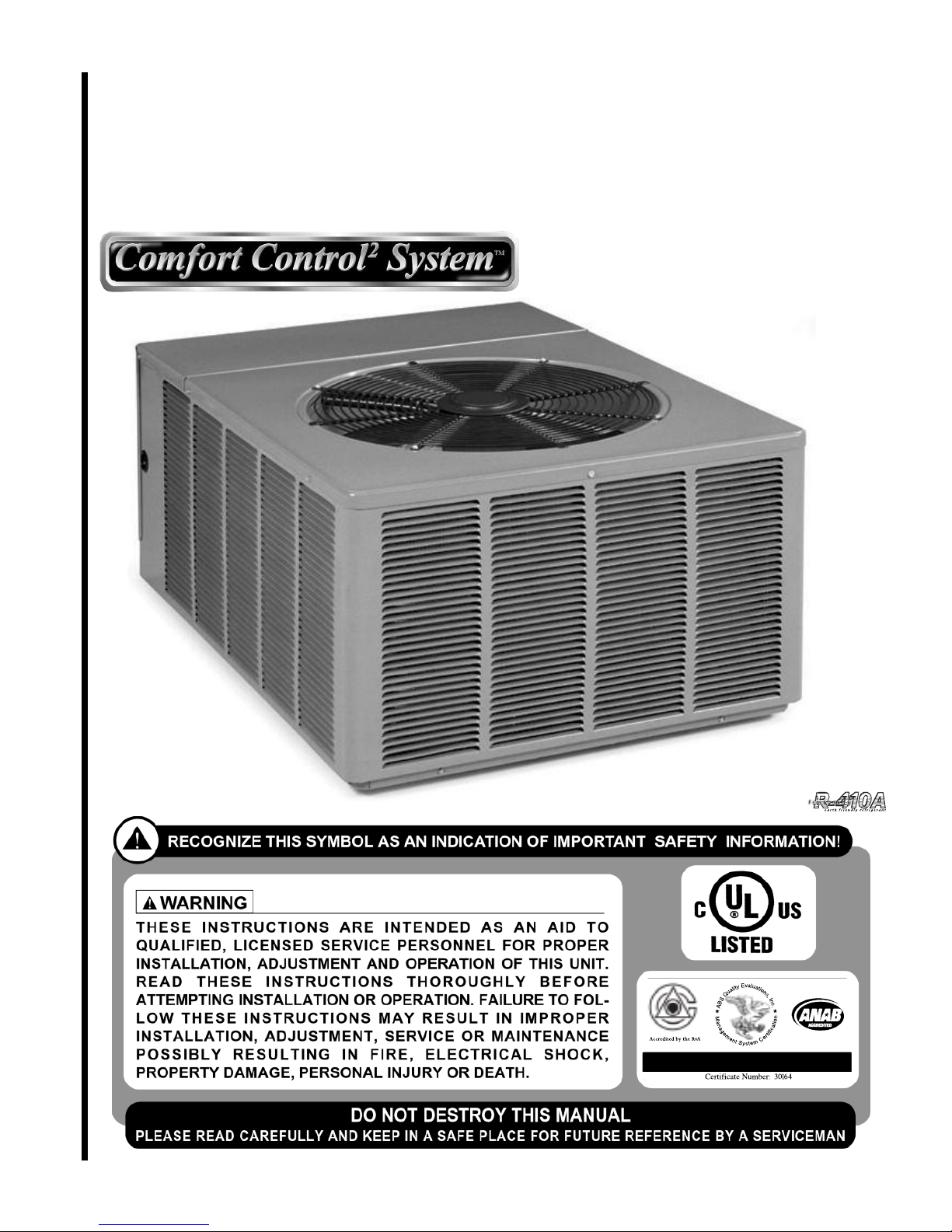
AIR-COOLED CONDENSING UNITS
(-)ARL-JEC 16 SEER
EQUIPPED WITH THE COMFORT CONTROL
2
SYSTEM™
INSTALLATION INSTRUCTIONS
[ ] INDICATES METRIC CONVERSIONS
ISO 9001:2000
Featuring Earth-Friendly
R-410A Refrigerant

TABLE OF CONTENTS
1.0 SAFETY INFORMATION . . . . . . . . . . . . . . . . . . . . . . . . . . . . . . . . . . . . . . . . . . . . 3
2.0 GENERAL INFORMATION . . . . . . . . . . . . . . . . . . . . . . . . . . . . . . . . . . . . . . . . . . 5
2.1 Checking Product Received . . . . . . . . . . . . . . . . . . . . . . . . . . . . . . . . . . . . 5
2.2 Application . . . . . . . . . . . . . . . . . . . . . . . . . . . . . . . . . . . . . . . . . . . . . . . . . . 5
2.3 Dimensions . . . . . . . . . . . . . . . . . . . . . . . . . . . . . . . . . . . . . . . . . . . . . . . . . 6
2
.4 Electrical and Physical Data . . . . . . . . . . . . . . . . . . . . . . . . . . . . . . . . . . . . 6
2.5 Proper Installation . . . . . . . . . . . . . . . . . . . . . . . . . . . . . . . . . . . . . . . . . . . . 7
3.0 LOCATING UNIT . . . . . . . . . . . . . . . . . . . . . . . . . . . . . . . . . . . . . . . . . . . . . . . . . . 7
3.1 Corrosive Environment . . . . . . . . . . . . . . . . . . . . . . . . . . . . . . . . . . . . . . . . 7
3.2 Condenser Location. . . . . . . . . . . . . . . . . . . . . . . . . . . . . . . . . . . . . . . . . . . 7
3.3 Operational Issues . . . . . . . . . . . . . . . . . . . . . . . . . . . . . . . . . . . . . . . . . . . . 8
3.4 For Condensers With Space Limitations . . . . . . . . . . . . . . . . . . . . . . . . . . . 8
3.5 Customer Satisfaction Issues . . . . . . . . . . . . . . . . . . . . . . . . . . . . . . . . . . . 8
3.6 Unit Mounting. . . . . . . . . . . . . . . . . . . . . . . . . . . . . . . . . . . . . . . . . . . . . . . . 8
3
.7 Factory-Preferred Tie-Down Method . . . . . . . . . . . . . . . . . . . . . . . . . . . . . . 8
4.0 REFRIGERANT CONNECTIONS . . . . . . . . . . . . . . . . . . . . . . . . . . . . . . . . . . . . . 9
4.1 Tools Required for Installing & Servicing R-410A Models . . . . . . . . . . . . . . 9
4.2 Specifications of R-410A . . . . . . . . . . . . . . . . . . . . . . . . . . . . . . . . . . . . . . 10
4.3 Quick Reference Guide for R-410-A . . . . . . . . . . . . . . . . . . . . . . . . . . . . . 10
5.0 REPLACEMENT UNITS. . . . . . . . . . . . . . . . . . . . . . . . . . . . . . . . . . . . . . . . . . . . 11
6.0 INDOOR COIL . . . . . . . . . . . . . . . . . . . . . . . . . . . . . . . . . . . . . . . . . . . . . . . . . . . 11
6.1 Location . . . . . . . . . . . . . . . . . . . . . . . . . . . . . . . . . . . . . . . . . . . . . . . . . . . 11
7.0 INTERCONNECTING TUBING . . . . . . . . . . . . . . . . . . . . . . . . . . . . . . . . . . . . . . 11
7.1 Vapor and Liquid Lines . . . . . . . . . . . . . . . . . . . . . . . . . . . . . . . . . . . . . . . 11
7.2 Maximum Length of Lines . . . . . . . . . . . . . . . . . . . . . . . . . . . . . . . . . . . . . 12
7.3 Outdoor Unit Installed Above or Below Indoor Coil . . . . . . . . . . . . . . . . . . 12
7.4 Tubing Installation . . . . . . . . . . . . . . . . . . . . . . . . . . . . . . . . . . . . . . . . . . . 13
7.5 Tubing Connections . . . . . . . . . . . . . . . . . . . . . . . . . . . . . . . . . . . . . . . . . . 15
7.6 Leak Testing . . . . . . . . . . . . . . . . . . . . . . . . . . . . . . . . . . . . . . . . . . . . . . . 15
8.0 COMPRESSOR CRANKCASE HEAT (CCH) . . . . . . . . . . . . . . . . . . . . . . . . . . . 15
9.0 HARD START COMPONENTS . . . . . . . . . . . . . . . . . . . . . . . . . . . . . . . . . . . . . . 16
10.0 HIGH AND LOW PRESSURE CONTROLS (HPC AND LPC) . . . . . . . . . . . . . . . 16
10.1 Evacuation Procedure . . . . . . . . . . . . . . . . . . . . . . . . . . . . . . . . . . . . . . . . 16
11.0 CONDENSING UNITS EQUIPPED WITH THE COMFORT CONTROL
2
SYSTEM™ . . . . . . . . . . . . . . . . . . . . . . . . . . . . . . . . . . . . . . . . . . . . . . . . . . . . . . 17
11.1 Control Description . . . . . . . . . . . . . . . . . . . . . . . . . . . . . . . . . . . . . . . . . . 17
11.2 Comfort Control
2
System™ Control Wiring . . . . . . . . . . . . . . . . . . . . . . . . 18
11.3 Comfort Control
2
System™ ICC Control Operation . . . . . . . . . . . . . . . . . . 18
11.4 Active Compressor Protection Mode . . . . . . . . . . . . . . . . . . . . . . . . . . . . . 20
11.5 Test and Fault Recall Modes . . . . . . . . . . . . . . . . . . . . . . . . . . . . . . . . . . . 22
11.6 ICC Diagnostic Codes . . . . . . . . . . . . . . . . . . . . . . . . . . . . . . . . . . . . . 24-27
11.7 Conventional 24VAC Thermostat Control Wiring . . . . . . . . . . . . . . . . . . . 27
11.8 Typical Non-Communicating Thermostat Wiring Diagrams. . . . . . . . . . . . 28
11.9 ICC Control Operation with Conventional Thermostat Wiring . . . . . . . . . . 29
11.10 Active Compressor Protection Mode . . . . . . . . . . . . . . . . . . . . . . . . . . . . . 30
11.11 Test and Fault Recall Modes . . . . . . . . . . . . . . . . . . . . . . . . . . . . . . . . . . . 31
12.0 ELECTRICAL WIRING . . . . . . . . . . . . . . . . . . . . . . . . . . . . . . . . . . . . . . . . . . . . . 33
12.1 Power Wiring . . . . . . . . . . . . . . . . . . . . . . . . . . . . . . . . . . . . . . . . . . . . . . . 33
12.2 Grounding . . . . . . . . . . . . . . . . . . . . . . . . . . . . . . . . . . . . . . . . . . . . . . . . . 33
12.3 Control Wiring . . . . . . . . . . . . . . . . . . . . . . . . . . . . . . . . . . . . . . . . . . . . . . 33
13.0 START-UP AND PERFORMANCE . . . . . . . . . . . . . . . . . . . . . . . . . . . . . . . . . . . 34
14.0 CHECKING AIRFLOW . . . . . . . . . . . . . . . . . . . . . . . . . . . . . . . . . . . . . . . . . . . . . 34
15.0 CHECKING REFRIGERANT CHARGE . . . . . . . . . . . . . . . . . . . . . . . . . . . . . . . . 34
15.1 Charging Units With R-410A Refrigerant. . . . . . . . . . . . . . . . . . . . . . . . . . 35
15.2 Charging By Liquid Pressure . . . . . . . . . . . . . . . . . . . . . . . . . . . . . . . . . . . 35
15.3 Charging By Weight. . . . . . . . . . . . . . . . . . . . . . . . . . . . . . . . . . . . . . . . . . 35
15.4 Final Leak Testing . . . . . . . . . . . . . . . . . . . . . . . . . . . . . . . . . . . . . . . . . . . 35
16.0 ACCESSORIES . . . . . . . . . . . . . . . . . . . . . . . . . . . . . . . . . . . . . . . . . . . . . . . . . . 36
16.1 Remote Outdoor Temperature Model . . . . . . . . . . . . . . . . . . . . . . . . . . . . 36
17.0 TROUBLESHOOTING . . . . . . . . . . . . . . . . . . . . . . . . . . . . . . . . . . . . . . . . . . . . . 36
17.1 Comfort Control
2
System™ Initial Startup . . . . . . . . . . . . . . . . . . . . . . . . . 36
17.2 Replacement of Comfort Control
2
System™ Control Board . . . . . . . . . . . 37
17.3 Electrical Checks Flow Chart . . . . . . . . . . . . . . . . . . . . . . . . . . . . . . . . . . . 38
17.4 Cooling Mechanical Checks Flow Chart . . . . . . . . . . . . . . . . . . . . . . . . . . 39
17.5 General Trouble Shooting Chart . . . . . . . . . . . . . . . . . . . . . . . . . . . . . . . . 40
17.6 Service Analyzer Charts . . . . . . . . . . . . . . . . . . . . . . . . . . . . . . . . . . . . 41-45
17.7 Subcooling Calculation . . . . . . . . . . . . . . . . . . . . . . . . . . . . . . . . . . . . . . . 46
18.0 WIRING DIAGRAMS . . . . . . . . . . . . . . . . . . . . . . . . . . . . . . . . . . . . . . . . . . . . 47-48
2
Continued on next page ➜
3
1.0 SAFETY INFORMATION
!
WARNING
THESE INSTRUCTIONS ARE INTENDED AS AN AID TO QUALIFIED, LICENSED
SERVICE PERSONNEL FOR PROPER INSTALLATION, ADJUSTMENT AND
OPERATION OF THIS UNIT. READ THESE INSTRUCTIONS THOROUGHLY
BEFORE ATTEMPTING INSTALLATION OR OPERATION. FAILURE TO FOLLOW THESE INSTRUCTIONS MAY RESULT IN IMPROPER INSTALLATION,
ADJUSTMENT, SERVICE OR MAINTENANCE POSSIBLY RESULTING IN FIRE,
ELECTRICAL SHOCK, PROPERTY DAMAGE, PERSONAL INJURY OR DEATH.
!
WARNING
THE MANUFACTURER’S WARRANTY DOES NOT COVER ANY DAMAGE OR
DEFECT TO THE AIR CONDITIONER CAUSED BY THE ATTACHMENT OR USE
OF ANY COMPONENTS, ACCESSORIES OR DEVICES (OTHER THAN THOSE
AUTHORIZED BY THE MANUFACTURER) INTO, ONTO OR IN CONJUNCTION
WITH THE AIR CONDITIONER. YOU SHOULD BE AWARE THAT THE USE OF
UNAUT HOR IZ ED CO MPO NENTS , A CC ESS ORIES OR DEV ICE S MAY
ADVERSELY AFFECT THE OPERATION OF THE AIR CONDITIONER AND MAY
ALSO ENDANGER LIFE AND PROPERTY. THE MANUFACTURER DISCLAIMS
ANY RESPONSIBILITY FOR SUCH LOSS OR INJURY RESULTING FROM THE
USE OF SUCH UNAUTHORIZED COMPONENTS, ACCESSORIES OR DEVICES.
!
WARNING
DISCONNECT ALL POWER TO UNIT BEFORE STARTING MAINTENANCE.
FAILURE TO DO S O CAN CAUSE ELECTR ICAL S HOCK R ESULTING IN
SEVERE PERSONAL INJURY OR DEATH.
!
WARNING
DO NOT USE OXYGEN TO PURGE LINES OR PRESSURIZE SYSTEM FOR
LEAK TEST. OXYGEN REAC TS VIOLENTLY WITH OIL, WHICH CAN
CAUSE AN EXPLOSION RESULTING IN SEVERE PERSONAL INJURY OR
DEATH.
!
WARNING
THE UNIT MUST BE PERMANENTLY GROUNDED. FAILURE TO DO SO
CAN CAUSE ELECTRICAL SHOCK RESULTING IN SEVERE PERSONAL
INJURY OR DEATH.
!
WARNING
TURN OFF ELECTRIC POWER AT THE FUSE BOX OR SERVICE PANEL
BEFORE MAKING ANY ELECTRICAL CONNECTIONS.
ALSO, THE GROUND CONNECTION MUST BE COMPLETED BEFORE
MAKING LINE VOLTAGE CO NNECTIONS. F AILURE TO DO SO CA N
RESULT IN EL ECTRICAL SHOCK, SEVERE P ERSONAL INJURY OR
DEATH.
4
!
CAUTION
UNIT MAY START SUDDENLY AND WITHOUT WARNING
Solid red light indicates a thermostat call for unit operation is present at
the ICC control. ICC control will attempt to start unit after short cycle timer
expires or when in Active Protection mode will attempt to restart unit prior
to Lockout mode.
!
CAUTION
UNIT MAY START SUDDENLY AND WITHOUT WARNING
Solid red light indicates a thermostat call for unit operation is present at the
ICC. ICC will attempt to start unit after short cycle timer expires or when in
Active Protection mode will attempt to restart unit prior to Lockout mode.
!
CAUTION
THE TOP OF THE SCROLL COMPRESSOR SHELL IS HOT. TOUCHING THE
COMPRESSOR TOP MAY RESULT IN SERIOUS PERSONAL INJURY.
!
CAUTION
R-410A PRESSURES ARE APPROXIMATELY 60% HIGHER THAN R-22
PRESSURES. USE APPROPRIATE CARE WHEN USING THIS REFRIGERANT. FAILURE TO EXERCISE CARE MAY RESULT IN EQUIPMENT DAMAGE, OR PERSONAL INJURY.
!
CAUTION
THE COMPRESSOR HAS AN INTERNAL OVERLOAD PROTECTOR. UNDER
SOME CONDITIONS, IT CAN TAKE UP TO 2 HOURS FOR THIS OVERLOAD
TO RESET. MAKE SURE OVERLOAD HAS HAD TIME TO RESET BEFORE
CONDEMNING THE COMPRESSOR.
!
CAUTION
Only use evaporators approved for use on R-410A systems. Use of existing
R-22 evaporators can introduce mineral oil to the R-410A refrigerant forming two different liquids and decreasing oil return to the compressor. This
c
an result in compressor failure.
!
CAUTION
When coil is installed over a finished ceiling and/or living area, it is
rec ommen ded t hat a se con dar y she et m eta l con den sat e pan b e
constructed and installed under entire unit. Failure to do so can result
in property damage.
!
CAUTION
R-410A systems operate at higher pressures than R-22 systems. Do not use
R-22 service equipment or components on R-410A equipment.
2.0 GENERAL INFORMATION
The (-)ARL-series of condensing units are designed to operate using the Comfort
Control
2
or traditional 24VAC controls. These units are equipped with Comfort
Control
2
. To take full advantage of the Comfort Control2System™, the preferred
method of installation is using the Comfort Control
2
. Your installation must have
these components to use the Comfort Control
2
:
•
(-)ARL condensing unit equipped with Comfort Control
2
• An air handler or furnace equipped with Comfort Control
2
• A Comfort Control2thermostat
If your installation does not meet the above requirements, you must use traditional
24VAC controls.
This installation instruction manual contains complete instructions for installation
and setup using Comfort Control
2
or conventional 24VAC controls. Please refer to
the engineering Specification Sheets for complete performance data, thermostat,
and accessory listings.
The information contained in this manual has been prepared to assist in the proper
installation, operation and maintenance of the air conditioning system. Improper
installation, or installation not made in accordance with these instructions, can
result in unsatisfactory operation and/or dangerous conditions (noise and component failure), and can cause the related warranty not to apply.
Read this manual and any instructions packaged with separate equipment required
to make up the system prior to installation. Retain this manual for future reference.
To achieve optimum efficiency and capacity, the indoor cooling coils listed in the
condensing unit specification sheet should be used.
2.1 CHECKING PRODUCT RECEIVED
Upon receiving unit, inspect it for any shipping damage. Claims for damage, either
apparent or concealed, should be filed immediately with the shipping company.
Check condensing unit model number, electrical characteristics and accessories to
determine if they are correct. Check system components (evaporator coil, condensing unit, evaporator blower, etc.) to make sure they are properly matched.
2.2 APPLICATION
Before specifying any air conditioning equipment, a survey of the structure and a
heat gain calculation must be made. A heat gain calculation begins by measuring
all external surfaces and openings that gain heat from the surrounding air and
quantifying that heat gain. A heat gain calculation also calculates the extra heat
load caused by sunlight and by humidity removal.
Air conditioning systems are sized on the cooling load calculation. There are two
capacities that enable the equipment to provide comfort. The first is sensible capacity.
Sensible heat is the heat energy measured on the dry bulb thermometer as it is
added or removed.
The second form of heat is called latent or hidden heat. This is heat held in the
humidity in the air.
A properly-sized unit removes both forms of heat, producing a comfortable living
space. An oversized system cycles on and off too quickly and does not properly
remove humidity, producing an uncomfortable living space. Select the indoor and
outdoor equipment combination based on the manufacturer’s engineering data.
After the equipment combination has been selected, satisfying both sensible and
latent conditioning requirements, the system must be properly installed. Only then
can the unit provide the comfort the manufacturer intends.
There are several factors that the installers must consider:
• Outdoor unit location • Proper equipment evacuation
• System refrigerant charge • Indoor unit airflow
• Indoor unit blower speed • Supply and return air duct design and sizing
• System air balancing • Diffuser and return air grille location and sizing
!
WARNING
TH E MANUFACTURER’S WARRANTY DOES NOT COVER ANY
DA MAGE OR DEFECT T O T HE
AIR CONDITIONER CAUSED BY
THE ATTACHMENT OR USE OF
ANY CO MPO NEN TS. ACC ESS
ORIES OR DEVICES (OTHER
THAN THOSE AUTHORIZED BY
THE MANUF ACTUR ER ) IN TO,
ONT O OR I N CON JUNCT ION
WI TH THE AI R C ON DITIONER.
YOU SHOULD BE AWARE THAT
THE USE OF U NAU THORI ZED
COMPONENTS, ACCESSORIES
OR DEVICES MAY ADVERSELY
AFF ECT TH E OP ERA TIO N
OF THE AIR CONDITIONER AND
MAY AL SO E NDA NGER L IFE
AND PROPERTY. THE MANUFACTUR ER DIS CLAIM S ANY
RES PONSI BIL ITY FOR SUC H
LO SS OR INJURY RESULTING
FRO M THE USE OF SU CH
UNAUTHORIZED COMPONENTS,
ACCESSORIES OR DEVICES.
MATCH ALL COMPONENTS:
• OUTDOOR UNIT
• INDOOR COIL/METERING DEVICE
• INDOOR AIR HANDLER/FURNACE
• REFRIGERANT LINES
5
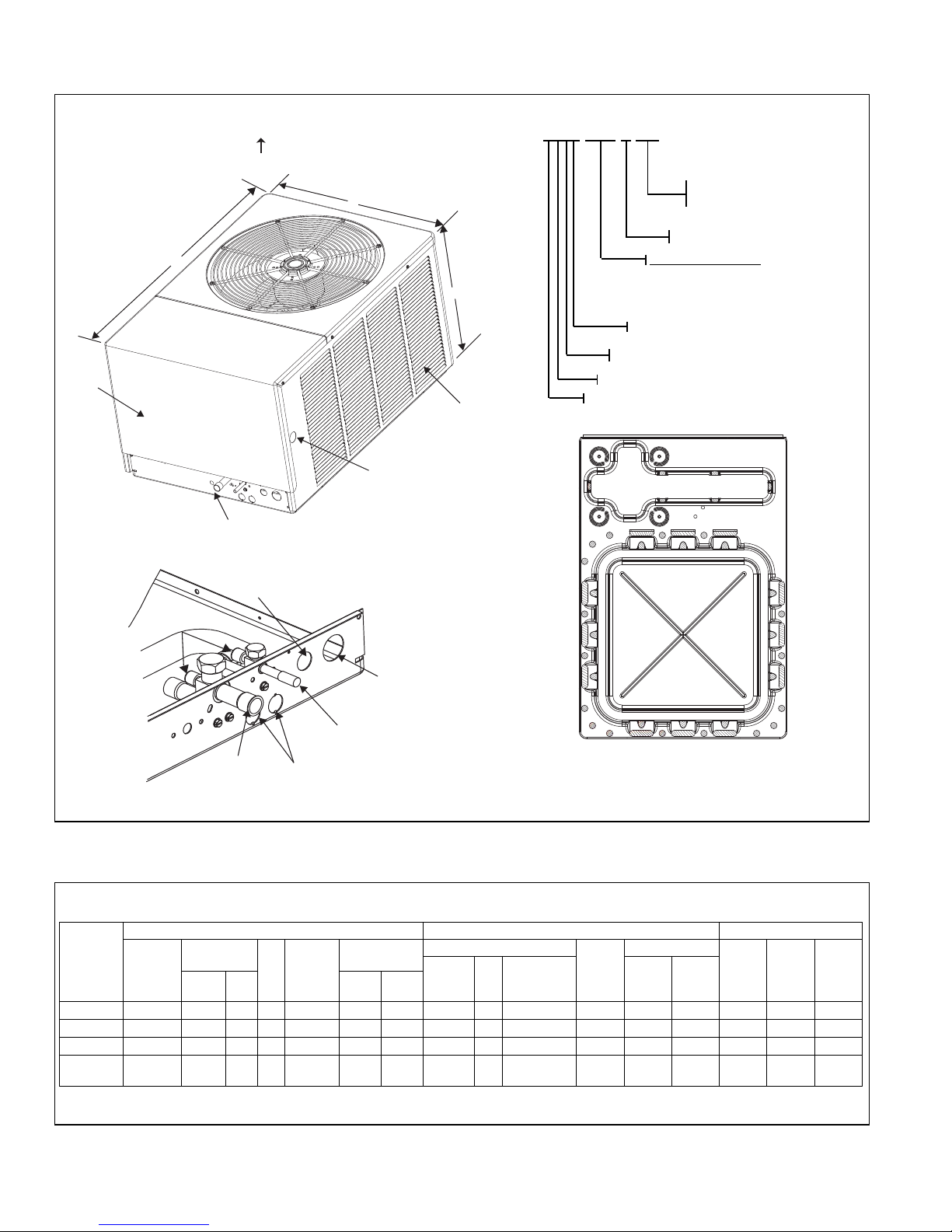
FIGURE 1
DIMENSIONS AND INSTALLATION CLEARANCES
UNIT MODEL NUMBER EXPLANATION
(-)ARL – 036 JEC
E
C = EQUIPPED WITH THE
C
OMFORT CONTROL
2
S
YSTEM™
J-208/230-1-60
(NOMINAL CAPACITY)
0
24 = 24000 BTU/HR
0
36 = 36000 BTU/HR
0
48 = 48000 BTU/HR
0
60 = 60000 BTU/HR
L = DESIGN SERIES (R-410A)
R = 16 SEER
A
= REMOTE CONDENSING UNIT
TRADE NAME
A
IR INLETS
(
LOUVERS)
A
LLOW 120 [305 mm]
MIN. CLEARANCE
3 SIDES
AIR DISCHARGE
ALLOW 600 [1524 mm] CLEARANCE
ALLOW 240 [610 mm]
ACCESS CLEARANCE
ACCESS
PANEL
L
W
H
ALTERNATE HIGH VOLTAGE
CONNECTION (KNOCKOUT)
1
1
1
/320[34 mm]
SERVICE
FITTINGS
LOW VOLTAGE
CONNECTION
7
/8" [22 mm]
HIGH VOLTAGE
CONNECTION
1
11
/32" [34 mm]
LIQUID LINE
CONNECTION
SERVICE ACCESS
TO ELECTRICAL &
VALVES ALLOW
24" [610 mm]
CLEARANCE
ONE SIDE
2
7
/8" [73 mm] DIA.
ACCESSORY
KNOCKOUTS
VAPOR LINE
CONNECTION
A
-00002
BASE PAN
ALLOW 24" [610 mm]
ACCESS CLEARANCE
ALTERNATE LINE VOLTAGE
ENTRY (KNOCKOUT)
1
1
1
⁄32" [34 MM]
CONNECT THE LINE
VOLTAGE CONDUIT TO
THE BOTTOM OF THE
CONTROL BOX
AIR INLETS
(LOUVERS)
ALLOW 6” [152 mm]
MIN. CLEARANCE
3
SIDES
ACCESS
PANEL
AIR DISCHARGE
ALLOW 60" [1524 mm] CLEARANCE
TABLE 1
(-)ARL-JEC ELECTRICAL DATA
Model
Number
Phase
Frequency
(Hz)
Voltage
(Volts)
Compressor
Fan
Motor
(FLA)
Min. Circuit
Ampacity
Amperes
Fuse or HACR
Circuit Breaker
Outdoor Coil Weight
Min.
Amperes
Max.
Amperes
Face Area
Sq. Ft. [m
2
]
No.
Rows
CFM [L/s}
R-410a
Oz. [g]
Net
Lbs. [kg]
Shipping
Lbs. [kg]
Height
“H”
(Inches)
Length
“L”
(Inches)
Width
“W”
(Inches)
ELECTRICAL PHYSICAL DIMENSIONAL DATA
(RLA) (LRA)
(-)ARL-024JEC 1-60-208/230 10.3/10.3 52 0.8 14/14 20/20 20/20 15.8 [1.47] 1 2285 [1078] 117 [3311] 190 [86.2] 200 [90.7] 23 44-3/8 31-1/2
(-)ARL-036JEC 1-60-208/230 16.7/16.7 82 1.0 22/22 30/30 35/35 15.8 [1.47] 1 3900 [1841] 157 [4445] 236 [107] 246 [111.6] 33 44-3/8 31-1/2
(-)ARL-048JEC 1-60-208/230 21.2/21.2 96 1.0 28/28 35/35 45/45 15.8 [1.47] 1 3900 [1841] 154 [4354] 236 [107] 246 [111.6] 33 44-3/8 31-1/2
HS* 3500 [1652]
224 [6250] 305 [138.4] 315 [142.8] 33 44-3/8 31-1/2
(-)ARL-060JEC 1-60-208/230 25.6/25.6 118 2.8 35/35 45/45 60/60 23.0 [2.14] 2
LS* 2800 [1322]
*HS = high speed
*LS = low speed
BOTTOM VIEW SHOWING DRAIN OPENINGS
(\\\\\ SHADED AREAS).
LINE VOLTAGE
ENTRY
111⁄32" [34 MM]
CONNECT THE LINE
VOLTAGE CONDUIT TO
THE BOTTOM OF THE
CONTROL BOX
LINE VOLTAGE
ENTRY
7
⁄8" [22 MM]
2.3 DIMENSIONS
2.4 ELECTRICAL & PHYSICAL DATA
6
2.5 PROPER INSTALLATION
Proper sizing and installation of this equipment is critical to achieve optimal performance. Use the information in this Installation Instruction Manual and reference the
applicable Engineering Specification Sheet when installing this product.
IMPORTANT: This product has been designed and manufactured to meet ENERG
Y STAR
®
c
riteria for energy efficiency when matched with appropriate coil components. However, proper refrigerant charge and proper airflow are critical to achieve
rated capacity and efficiency. Installation of this product should follow the manufacturer’s refrigerant charging and airflow instructions. Failure to confirm proper
charge and airflow may reduce energy efficiency and shorten equipment life.
3.0 LOCATING UNIT
3.1 Corrosive Environment
The metal parts of this unit may be subject to rust or deterioration if exposed to a
corrosive environment. This oxidation could shorten the equipment’s useful life.
Corrosive elements include, but are not limited to, salt spray, fog or mist in seacoast
areas, sulphur or chlorine from lawn watering systems, and various chemical contaminants from industries such as paper mills and petroleum refineries.
If the unit is to be installed in an area where contaminants are likely to be a problem, special attention should be given to the equipment location and exposure.
• Avoid having lawn sprinkler heads spray directly on the unit cabinet.
• In coastal areas, locate the unit on the side of the building away from the water-
front.
• Shielding provided by a fence or shrubs may give some protection, but cannot
violate minimum airflow and service access clearances.
• Elevating the unit off its slab or base enough to allow air circulation will help
avoid holding water against the basepan.
Regular maintenance will reduce the build-up of contaminants and help to protect
the unit’s finish.
• Frequent washing of the cabinet, fan blade and coil with fresh water will remove
most of the salt or other contaminants that build up on the unit.
• Regular cleaning and waxing of the cabinet with a good automobile polish will
provide some protection.
• A good liquid cleaner may be used several times a year to remove matter that
will not wash off with water.
Several different types of protective coatings are offered in some areas. These
coatings may provide some benefit, but the effectiveness of such coating materials
cannot be verified by the equipment manufacturer.
3.2 CONDENSER LOCATION
Consult local and national building codes and ordinances for special installation
requirements. Following location information will provide longer life and simplified
servicing of the outdoor condenser.
NOTE: These units must be installed outdoors. No ductwork can be attached, or
other modifications made, to the discharge grille. Modifications will affect performance or operation.
!
WARNING
DIS CONNE CT ALL P OWE R T O UNI T B EFO RE S TAR TIN G
MAINTENANCE. FAILURE TO DO SO CAN CAUSE ELECTRICAL SHOCK
RESULTING IN SEVERE PERSONAL INJURY OR DEATH.
7

3.3 Operational Issues
• IMPORTANT: Locate the unit in a manner that will not prevent, impair or compromise the performance of other equipment horizontally installed in proximity
to the unit. Maintain all required minimum distances to gas and electric meters,
d
ryer vents, exhaust and inlet openings. In the absence of National Codes, or
manufacturers’ recommendations, local code recommendations and requirements will take precedence.
• Refrigerant piping and wiring should be properly sized and kept as short as
possible to avoid capacity losses and increased operating costs.
• Locate the unit where water run off will not create a problem with the equipment. Position the unit away from the drip edge of the roof whenever possible.
Units are weatherized, but can be affected by the following:
o Water pouring into the unit from the junction of rooflines, without protective
guttering. Large volumes of water entering the heat pump while in operation
can impact fan blade or motor life, and coil damage may occur to a heat
pump if moisture cannot drain from the unit under freezing conditions.
o Freezing moisture, or sleeting conditions, can cause the cabinet to ice-over
prematurely and prevent heat pump operation, requiring backup heat, which
generally results in less economical operation.
• Closely follow clearance recommendations on Page 6.
o 24” to the service panel access
o 60” above heat pump fan discharge (unit top) to prevent recirculation
o 6” to heat pump coil grille air inlets
3.4 For Units With Space Limitations
FOR CONDENSERS WITH SPACE LIMITATIONS
In the event that a space limitation exists, we will permit the following clearances:
Single Unit Applications: Clearances below 6 inches will reduce unit capacity and
efficiency. Do not reduce the 60-inch discharge, or the 24-inch service clearances.
Multiple Unit Applications: When multiple condenser grille sides are aligned, a 6inch per unit clearance is recommended, for a total of 12” between two units. Two
combined clearances below 12 inches will reduce capacity and efficiency. Do not
reduce the 60-inch discharge, or 24-inch service, clearances.
3.5 Customer Satisfaction Issues
• The condensing unit should be located away from the living, sleeping and
recreational spaces of the owner and those spaces on adjoining property.
• To prevent noise transmission, the mounting pad for the outdoor unit should
not be connected to the structure, and should be located sufficient distance
above grade to prevent ground water from entering the unit.
3.6 Unit Mounting
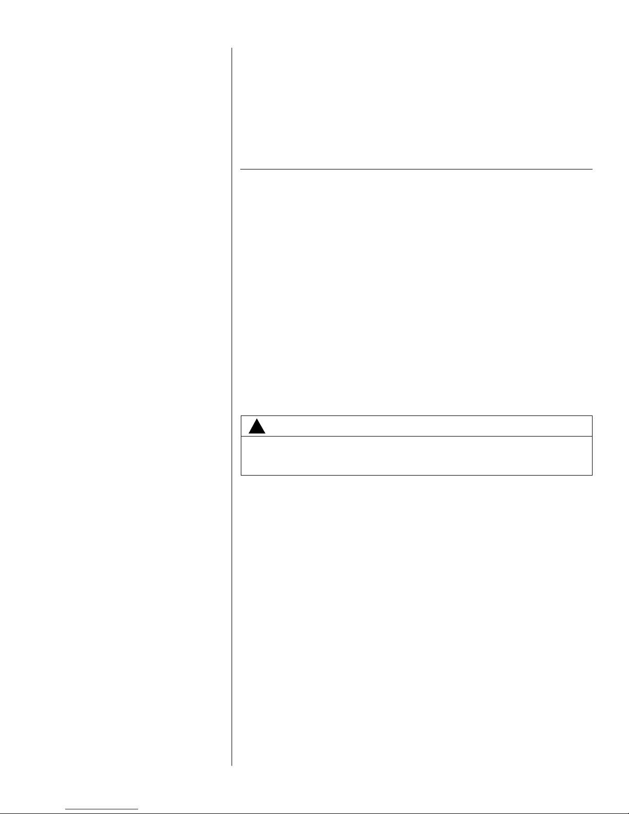
If elevating the condensing unit, either on a flat roof or on a slab, observe the
following guidelines.
• The base pan provided elevates the heat pump 3/4” above the base pad.
• If elevating a unit on a flat roof, use 4” x 4” (or equivalent) stringers positioned
to distribute unit weight evenly and prevent noise and vibration (see Figure 2).
NOTE: Do not block drain openings shown in Figure 1.
3.7 Factory-Preferred Tie-Down Method
INSTRUCTIONS
IMPORTANT: These instructions are intended as a guide to securing equipment for
wind-load ratings of “120 MPH sustained wind load” and “3-second, 150 MPH gust.”
While this procedure is not mandatory, the Manufacturer does recommend that
equipment be properly secured in areas where high wind damage may occur.
STEP 1: Before installing, clear pad of any dirt or debris.
IMPORTANT: The pad must be constructed of industry-approved materials,
and must be thick enough to accommodate the concrete fastener.
STEP 2: Center base pan on pad, ensuring it is level.
8
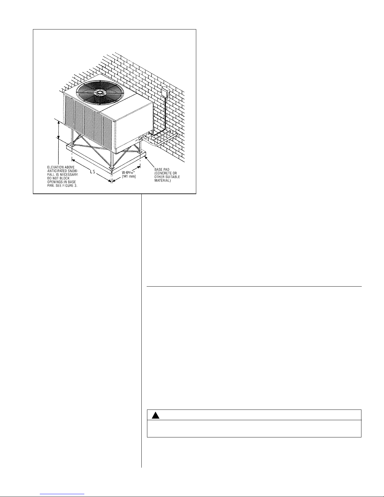
STEP 3: Using basepad as a guide, mark spots on concrete where 4 holes will be
drilled (see Figure 3).
STEP 4: Drill four pilot holes in pad, ensuring that the hole is at least 1/4” deeper
than the concrete screw being used.
STEP 5: Center basepan over pre-drilled holes and insert concrete screws.
STEP 6: Tighten concrete screws.
NOTE: Do not over-tighten the concrete screws. Doing so can weaken the
integrity of the concrete screw and cause it to break.
STEP 7: Finish unit assembly per unit’s installation instructions.
4.0 REFRIGERANT CONNECTIONS
All units are factory charged with Refrigerant 410A. All models are supplied with
service valves. Keep tube ends sealed until connection is to be made to prevent
system contamination.
4.1 Tools Required For Installing & Servicing R-410A Models
Manifold Sets:
-Up to 800 PSIG High side
-Up to 250 PSIG Low Side
-550 PSIG Low Side Retard
Manifold Hoses:
-Service Pressure Rating of 800 PSIG
Recovery Cylinders:
-400 PSIG Pressure Rating
-Dept. of Transportation 4BA400 or BW400
9
!
CAUTION
R-410A systems operate at higher pressures than R-22 systems. Do not use
R-22 service equipment or components on R-410A equipment.
FIGURE 2
R
ECOMMENDED ELEVATED INSTALLATION
4.2 Specifications of R-410A:
Application: R-410A is not a drop-in replacement for R-22; equipment designs
must accommodate its higher pressures. It cannot be retrofitted into R-22 heat
pumps.
Physical Properties: R-410A has an atmospheric boiling point of -62.9°F and its
saturation pressure at 77°F is 224.5 psig.
Composition: R-410A is an azeotropic mixture of 50% by weight difluoromethane
(HFC-32) and 50% by weight pentafluoroethane (HFC-125).
Pressure: The pressure of R-410A is approximately 60% (1.6 times) greater
than R-22. Recovery and recycle equipment, pumps, hoses and the like need to
have design pressure ratings appropriate for R-410A. Manifold sets need to range
up to 800 psig high-side and 250 psig low-side with a 550 psig low-side retard.
Hoses need to have a service pressure rating of 800 psig. Recovery cylinders need
to have a 400 psig service pressure rating. DOT 4BA400 or DOT BW400.
Combustibility: At pressures above 1 atmosphere, mixture of R-410A and air can
become combustible. R-410A and air should never be mixed in tanks or supply
lines, or be allowed to accumulate in storage tanks. Leak checking should
never be done with a mixture of R-410A and air. Leak checking can be per-
formed safely with nitrogen or a mixture of R-410A and nitrogen.
4.3 Quick Reference Guide For R-410A
• R-410A refrigerant operates at approximately 60% higher pressure (1.6 times)
than R-22. Ensure that servicing equipment is designed to operate with R-410A.
• R-410A refrigerant cylinders are pink in color.
• R-410A, as with other HFC’s is only compatible with POE oils.
10
FIGURE 3
S
CREW LOCATIONS
TABLE 2
DIMENSIONS
MODEL NUMBER LWAB CD
(-)ARL-024/036/048/060 41.5 29.813 15 38 3.5 26.5
• Vacuum pumps will not remove moisture from oil.
• R-410A systems are to be charged with liquid refrigerants. Prior to March 1999,
R-410A refrigerant cylinders had a dip tube. These cylinders should be kept
upright for equipment charging. Post March 1999 cylinders do not have a dip
tube and should be inverted to ensure liquid charging of the equipment.
• Do not install a suction line filter drier in the liquid line.
• A liquid line filter drier is standard on every unit. Only manufacturer approved liquid line filter driers can be used. These are Sporlan (CW083S) and Alco
(80K083S) driers. These filter driers are rated for minimum working pressure of
600 psig.
• Desiccant (drying agent) must be compatible for POE oils and R-410A.
5.0 REPLACEMENT UNITS
To prevent failure of a new condensing unit, the existing evaporator tubing system
must be correctly sized and cleaned or replaced. Care must be exercised that the
expansion device is not plugged. For new and replacement units, a liquid line filter
drier should be installed and refrigerant tubing should be properly sized. Test the oil
for acid. If positive, a suction line filter drier is mandatory.
IMPORTANT: WHEN REPLACING AN R-22 U NIT WITH AN R-410A UNIT,
EITHER REPLACE THE LINE SET OR ENSURE THAT THE EXISTING LINE SET
IS THOROUGHLY CLEANED OF ANY OLD OIL OR DEBRIS.
6.0 INDOOR COIL
REFER TO INDOOR COIL MANUFACTURER’S INSTALLATION INSTRUCTIONS.
IMPORTANT: The manufacturer is not responsible for the performance and opera-
tion of a mismatched system, or for a match listed with another manufacturer’s coil.
NOTE: All (-)ARL units must be installed with a TXV Evaporator.
The thermostatic expansion valve is specifically designed to operate with R-410A.
DO NOT use an R-22 TXV or evaporator. The existing evaporator must be
replaced with the factory specified TXV evaporator specifically designed for
R-410A.
6.1 Location
Do not install the indoor coil in the return duct system of a gas or oil furnace.
Provide a service inlet to the coil for inspection and cleaning. Keep the coil pitched
toward the drain connection.
7.0 INTERCONNECTING TUBING
7.1 Vapor and Liquid Lines
Keep all lines sealed until connection is made.
Make connections at the indoor coil first.
11
!
CAUTION
Only use evaporators approved for use on R-410A systems. Use of existing R-22
evaporators can introduce mineral oil to the R-410A refrigerant forming two different liquids and decreasing oil return to the compressor. This can result in compressor failure.
!
CAUTION
When c oil is i nstal led ove r a f inish ed cei lin g an d/or l ivi ng are a, it i s
rec ommen ded t hat a s eco ndary s hee t met al c ond ens ate pan b e
construct ed an d installe d under entire unit. Failure to do so can r esult
in property damage.
12
Refer to Line Size Information in Tables 3, 4 and 5 for correct size and multipliers to
be used to determine capacity for various vapor line diameters and lengths of run.
The losses due to the lines being exposed to outdoor conditions are not included.
The factory refrigeration charge in the outdoor unit is sufficient for 15 feet of interconnecting lines. The factory refrigeration charge in the outdoor unit is sufficient for
the unit and 15 feet of standard size interconnecting liquid and vapor lines. For different lengths, adjust the charge as indicated below.
1/4” ± .3 oz. per foot
5/16” ± .4 oz. per foot
3/8” ± .6 oz. per foot
1/2” ± 1.2 oz. per foot
7.2 Maximum Length of Lines
The maximum length of interconnecting line is 150 feet. Always use the shortest
length possible with a minimum number of bends. Additional compressor oil is not
required for any length up to 150 feet.
NOTE: Excessively long refrigerant lines cause loss of equipment capacity.
7.3 Outdoor Unit Installed Above or Below Indoor Coil
Use the following guidelines when installing the unit:
1. Expansion Valve Coil:
a. The vertical separation cannot exceed the value in Tables 4 and 5.
b. No changes are required for expansion valve coils.
2. It is recommended to use the smallest liquid line size permitted to minimize the
system charge.
3. Tables 4 and 5 may be used for sizing horizontal runs.
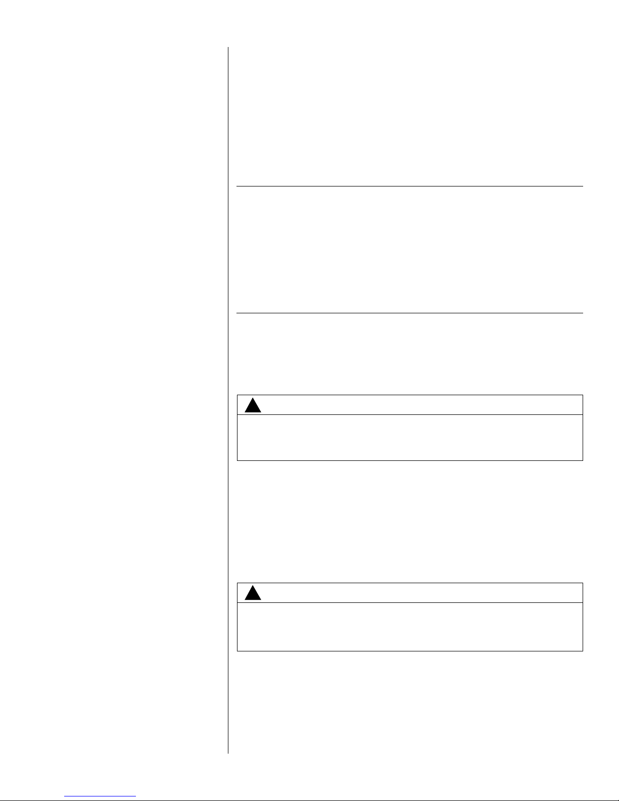
TABLE 3
VAPOR LINE CAPACITY MULTIPLIER
024
(-)ARL
Unit Vapor Line
Connection Size
(inches I.D.) [mm]
Vapor Line Run
Feet [m]
3/4” [19.05] I.D.
Sweat
7/8” [22.23] I.D.
Sweat
7/8” [22.23] I.D.
Sweat
7/8” [22.23] I.D.
Sweat
5/8” [15.88]
Optional
5/8” [15.88]
Optional
5/8” [15.88]
Optional
3/4” [19.05]
Optional
25‘ [7.62]
50’ [15.24]
75’ [22.86]
100’ [30.48]
125’ [38.10]
150’ [45.72]
Opt.
Std.
Opt.
Opt.
Std.
Opt.
Opt.
Std.
Opt.
Opt.
Std.
Opt.
Opt.
Std.
Opt.
Opt.
Std.
Opt.
3/4” [19.05]
Standard
3/4” [19.05]
Standard
3/4” [19.05]
Standard
7/8” [22.23]
Standard
——
7/8” [22.23]
Optional
—
1.00 0.98 0.98 0.99
1.00 1.00 1.00 1.00
N/A N/A 1.02 N/A
0.99 0.96 0.96 0.97
1.00 0.99 0.99 0.99
N/A N/A 1.00 N/A
0.98 0.96 0.94 0.96
0.99 0.98 0.98 0.99
N/A N/A 1.00 N/A
0.97 0.94 0.92 0.95
N/A N/A 0.98 0.98
N/A N/A N/A N/A
0.97 0.93 0.90 0.94
N/A N/A 0.97 0.97
N/A N/A N/A N/A
0.96 0.92 0.88 0.93
N/A N/A 0.96 0.97
N/A N/A N/A N/A
036 048 060
Vapor Line Diameter (inches O.D.) [mm]
NOTES:
1. Do NOT exceed the limits in the liquid and suction line sizing charts.
2. Do NOT use 7/8 OD suction lines in 2 or 3-ton applications.
3. Do NOT use 1-1/8 OD suction line in ANY application.
4. 2 and 3-ton line sets over 75 feet MUST use the optional suction line.
13
7.4 Tubing Installation
Observe the following when installing correctly sized type “L” refrigerant tubing
between the condensing unit and evaporator coil:
• If a portion of the liquid line passes through a hot area where liquid refrigerant
can be heated to form vapor, insulating the liquid line is required.
• Use clean, dehydrated, sealed refrigeration grade tubing.
• Always keep tubing sealed until tubing is in place and connections are to be
made.
• Blow out the liquid and vapor lines with dry nitrogen before connecting to the
outdoor unit and indoor coil. Any debris in the line set will end up plugging the
expansion device.
• As an added precaution, a high quality filter drier is standard on R-410A units.
• Do not allow the vapor line and liquid line to be in contact with each other. This
causes an undesirable heat transfer resulting in capacity loss and increased
power consumption. The vapor line must be insulated.
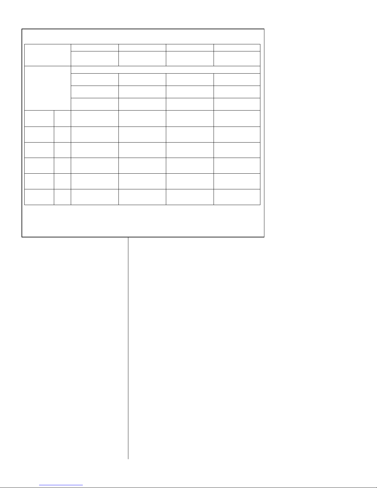
L
IQUID LINE SIZE - OUTDOOR UNIT ABOVE INDOOR COIL
R-410A
System
Capacity
Model
Line Size
Connection
Size (Inch
I.D.) [mm]
Line Size
(Inch O.D.)
[mm]
Minimum Vertical Separation - Feet [m]
1/4” [6.35] 0 1 [0.31] 24 [7.32] 50 [15.24] 76 [23.17] 102 [31.09]
-024 3/8” [9.53] 5/16” [7.93]* 000000
3/8” [9.52] 000000
5/16” [7.93] 0005 [1.52] 13 [3.96] 20 [6.10]
-036 3/8” [9.53] 3/8” [9.52]* 00 0000
1/2” [12.70] 000000
5/16” [7.93] 0007 [2.13] 28 [8.53] 50 [15.24]
-048 3/8” [9.53] 3/8” [9.52]* 00 0000
1/2” [12.70] 000000
3/8” [9.52]* 00 0000
-060 3/8” [9.53]
1/2” [12.70] 000000
25 [7.62] 50 [15.24] 75 [22.86] 100 [30.48] 125 [38.1] 150 [45.72]
Liquid Line Size
Outdoor Unit Above Indoor Coil (Cooling Only - Does not apply to Heat Pumps)
Total Equivalent Length - Feet [m]
LIQUID LINE SIZE - OUTDOOR UNIT BELOW INDOOR COIL
R-410A
System
Capacity
Model
Line Size
Connection
Size (Inch
I.D.) [mm]
Line Size
(Inch O.D.)
[mm]
Maximum Vertical Separation - Feet [m]
1/4” [6.35] 13 [3.96] N/A N/A N/A N/A N/A
-024 3/8” [9.53] 5/16” [7.93]* 25 [7.62] 21 [6.40] 17 [5.18] 13 [3.96] 9 [2.74] N/A
3/8” [9.52] 25 [8.23] 26 [7.93] 25 [7.62] 23 [7.01] 22 [6.71] 20 [6.10]
5/16” [7.93] 15 [4.57] N/A N/A N/A N/A N/A
-036 3/8” [9.53] 3/8” [9.52]* 19 [5.79] 17 [5.18] 15 [4.57] 12 [3.66] 10 [3.05] N/A
1/2” [12.70] 21 [6.40] 21 [6.40] 20 [6.10] 20 [6.10] 19 [5.79] 19 [5.79]
5/16” [7.93] 25 [9.14] 17 [5.18] N/A N/A N/A N/A
-048 3/8” [9.53] 3/8” [9.52]* 25 [11.89] 34 [10.36] 30 [9.14] 25 [7.62] 21 [6.40] 17 [5.18]
1/2” [12.70] 25 [12.80] 41 [12.50] 41 [12.50] 40 [12.19] 39 [11.89] 38 [11.58]
3/8” [9.52]* 25 [17.98] 49 [14.94] 40 [12.19] 30 [9.14] 20 [6.10] 10 [3.05]
-060 3/8” [9.53]
1/2” [12.70] 25 [19.51] 50 [18.90] 61 [18.59] 60 [18.29] 59 [17.98] 57 [17.37]
25 [7.62] 50 [15.24] 75 [22.86] 100 [30.48] 125 [38.1] 150 [45.72]
Liquid Line Size
Outdoor Unit Below Indoor Coil (Cooling Only - Does not apply to Heat Pumps)
Total Equivalent Length - Feet [m]
T
ABLE 4
(
-)ARL LIQUID LINE SIZING
NOTES: N/A = Application Not Recommended
*Standard Line Size
NOTES: N/A = Application Not Recommended
*Standard Line Size
14
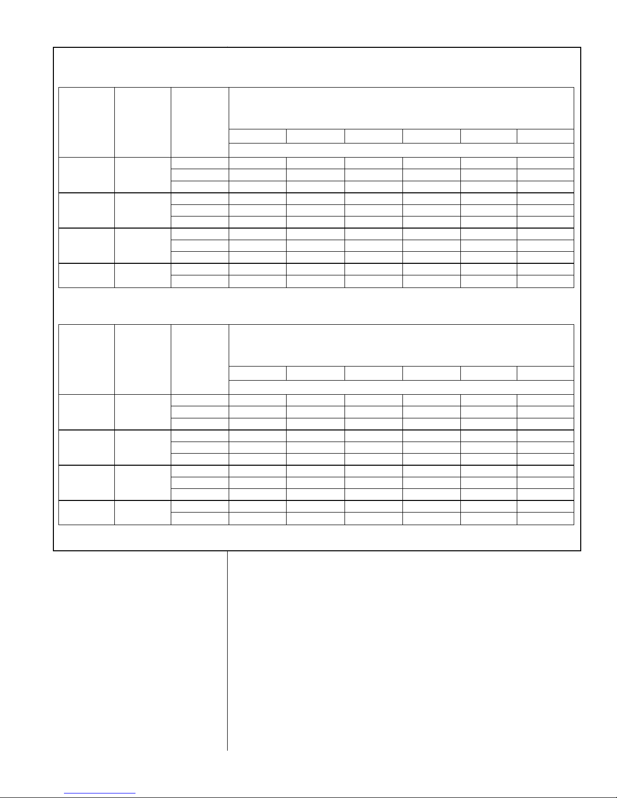
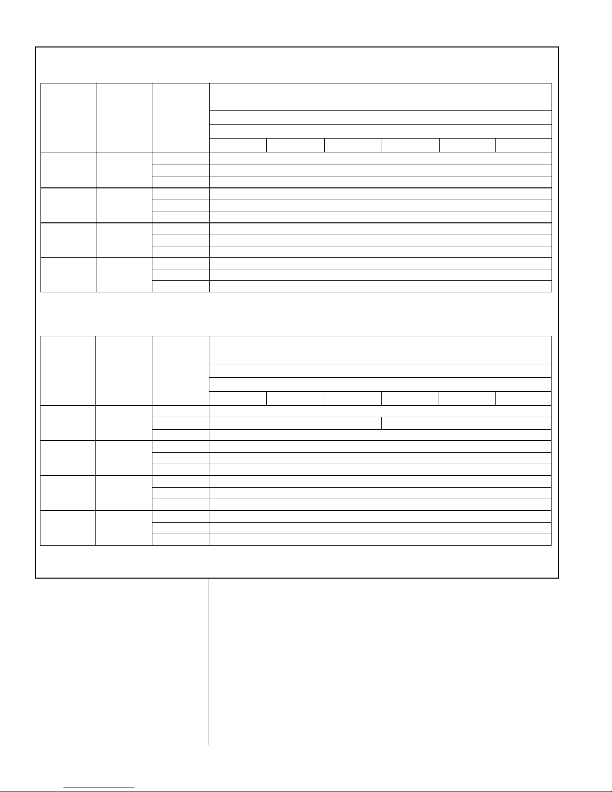
T
ABLE 5
(
-)ARL SUCTION LINE SIZING
SUCTION LINE SIZE - OUTDOOR UNIT ABOVE INDOOR COIL
R-410A
System
Capacity
Model
Line Size
Connection
Size (Inch
I.D.) [mm]
Line Size
(Inch O.D.)
[mm]
Outdoor Unit ABOVE Indoor Coil (Cooling Only - Does not apply to Heat Pumps)
Total Equivalent Length - Feet [m]
5/8” [15.88] Same as Liquid Line Size Table
-024 3/4” [19.05] 3/4” [19.05]* N/A
7/8” [22.23] N/A
5/8” [15.88] Same as Liquid Line Size Table
-036 3/4” [19.05] 3/4” [19.05]* N/A
7/8” [22.23] N/A
5/8” [15.88] Same as Liquid Line Size Table
-048 7/8” [22.22] 3/4” [19.05] Same as Liquid Line Size Table
7/8” [22.23]* Same as Liquid Line Size Table
3/4” [19.05] Same as Liquid Line Size Table
-060 7/8” [22.22] 7/8” [22.23]* Same as Liquid Line Size Table
1-1/8” [28.58] N/A
25 [7.62] 50 [15.24] 75 [22.86] 100 [30.48] 125 [38.1] 150 [45.72]
Suction Line Size
SUCTION LINE SIZE - OUTDOOR UNIT BELOW INDOOR COIL
R-410A
System
Capacity
Model
Line Size
Connection
Size
(Inch I.D.)
[mm]
Line Size
(Inch O.D.)
[mm]
Outdoor Unit BELOW Indoor Coil (Cooling Only - Does not apply to Heat Pumps)
Total Equivalent Length - Feet [m]
5/8” [15.88] Same as Liquid Line Size Table
-024 3/4” [19.05] 3/4” [19.05]* Same as Liquid Line Size Table N/A
7/8” [22.23] N/A
5/8” [15.88] Same as Liquid Line Size Table
-036 3/4” [19.05] 3/4” [19.05]* Same as Liquid Line Size Table
7/8” [22.23] N/A
5/8” [15.88] Same as Liquid Line Size Table
-048 7/8” [22.22] 3/4” [19.05] Same as Liquid Line Size Table
7/8” [22.23]* Same as Liquid Line Size Table
3/4” [19.05] Same as Liquid Line Size Table
-060 7/8” [22.22] 7/8” [22.23]* Same as Liquid Line Size Table
1-1/8” [28.58] N/A
25 [7.62] 50 [15.24] 75 [22.86] 100 [30.48] 125 [38.1] 150 [45.72]
Suction Line Size
• If tubing has been cut, make sure ends are deburred while holding in a position
to prevent chips from falling into tubing. Burrs such as those caused by tubing
cutters can affect performance dramatically, particularly on small liquid line
sizes.
• For best operation, keep tubing run as short as possible with a minimum number of elbows or bends.
• Locations where the tubing will be exposed to mechanical damage should be
avoided. If it is necessary to use such locations, the copper tubing should be
housed to prevent damage.
• If tubing is to be run underground, it must be run in a sealed watertight chase.
• Use care in routing tubing and do not kink or twist. Use a good tubing bender
on the vapor line to prevent kinking.
• Route the tubing using temporary hangers, then straighten the tubing and
install permanent hangers. Line must be adequately supported.
NOTES: Using suction line larger than shown in chart will result in poor oil return.
N/A = Application Not Recommended
*Standard Line Size
NOTES: Using suction line larger than shown in chart will result in poor oil return.
N/A = Application Not Recommended
*Standard Line Size
15
• The vapor line must be insulated to prevent dripping (sweating) and prevent
performance losses. Armaflex and Rubatex are satisfactory insulations for this
purpose. Use 1/2” minimum insulation thickness, additional insulation may be
required for long runs.
• Check Table 3 for the correct vapor line size. Check Table 4 for the correct liq-
uid line size.
7.5 Tubing Connections
Indoor coils have only a holding charge of dry nitrogen. Keep all tube ends sealed
until connections are to be made.
• Use type “L” copper refrigeration tubing. Braze the connections with the follow-
ing alloys:
–
copper to copper - 5%
– Silver alloy (no flux)
– copper to steel or brass - 35%
– silver alloy (with flux)
• Be certain both refrigerant shutoff valves at the outdoor unit are closed.
• Clean the inside of the fittings and outside of the tubing with steel wool or sand
cloth before soldering. Always keep chips, steel wool, dirt, etc., out of the inside
when cleaning.
• Assemble tubing part way into fitting. Apply flux all around the outside of the
tubing and push tubing into stop. This procedure will keep the flux from getting
inside the system.
• Remove the cap and schrader core from service port to protect seals from heat
damage.
• Use an appropriate heatsink material around the copper stub and the service
valves before applying heat.
• IMPORTANT: Do not braze any fitting with the TEV sensing bulb attached.
• Braze the tubing between the outdoor unit and indoor coil. Flow dry nitrogen
into a service port and through the tubing while brazing.
• After brazing – use an appropriate heatsink material to cool the joint and
remove any flux residue.
• The service valves are not backseating valves. To open the valves, remove the
valve cap with an adjustable wrench. Insert a 3/16” or 5/16” hex wrench into the
stem. Back out counterclockwise.
• Replace the valve cap finger tight then tighten an additional 1/2 hex flat for a
metal-to-metal seal.
7.6 Leak Testing
• Pressurize line set and coil through service fittings with dry nitrogen to 150
PSIG maximum. Leak test all joints using liquid detergent. If a leak is found,
recover pressure and repair.
8.0 COMPRESSOR CRANKCASE HEAT (CCH)
CCH is standard on these models due to refrigerant migration during the off cycle
that can result in a noisy start up.
Crankcase Heater Operation:
Supplemental Crankcase heat is required to prevent refrigerant migration in systems with relatively high system refrigerant charges.
The crankcase heater control is integrated into the Comfort Control
2
and is
designed for maximum energy savings.
Summary of operation:
• The crankcase heater is off whenever the compressor is running.
!
WARNING
DO NOT USE OXYGEN TO PURGE LINES OR PRESSURIZE SYSTEM FOR
LEAK TEST. OXYGEN REAC TS VIOLENTLY WITH OIL, WHICH CAN
CAUSE AN EXPLOSION RESULTING IN SEVERE PERSONAL INJURY OR
DEATH.
 Loading...