

Rheem A036CK08, A036CK12, A036CL08, A036CL12, A036CM08 Installation Instructions Manual
...Page 1
ISO 9001:2008
INSTALLATION INSTRUCTIONS
Package Gas Electric Featuring
Industry Standard R-410A Refrigerant
RKNL 13 SEER (3-5 TONS) SERIES
RKPL 14 SEER (3-5 TONS) SERIES
(14 SEER ONLY)
SUPERSEDES 92-23577-75-01
92-23577-75-02
Page 2

I.TABLE OF CONTENTS
. Table of Contents ..................................................................................................2
I
II. Introduction ............................................................................................................3
III. Checking Product Received ..................................................................................3
IV. Specifications.........................................................................................................3
A. General .............................................................................................................3
B. Major Components............................................................................................3
C. R-410A Refrigerant ...........................................................................................3
1. Specifications of R-410A...............................................................................3
2. Quick Reference Guide for R-410A ..............................................................4
. Evaporator Coil/TXV .....................................................................................4
3
4. Tools Required for Installing and Servicing R-410A Models.........................4
V. Safety Information..................................................................................................4
VI. Unit Dimensions.....................................................................................................5
VII. Installation..............................................................................................................7
A. General .............................................................................................................7
1. Pre-Installation Check ..................................................................................7
2. Location Considerations...............................................................................7
B. Outside Installation............................................................................................8
C. Attaching Exhaust and Combustion Air Inlet Hoods .........................................9
D. Cover Panel Installation/Conversion Procedure ...............................................9
E. Clearances ........................................................................................................9
F. Rooftop Installation .........................................................................................10
G. Ductwork .........................................................................................................10
H. Return Air ........................................................................................................11
VIII. Gas Supply, Condensate Drain and Piping .........................................................13
A. Gas Connection ..............................................................................................13
B. LP Conversion.................................................................................................14
C. NOx Models ....................................................................................................14
D. Adjusting or Checking Furnace Input ..............................................................15
E. Condensate Drain ...........................................................................................16
IX. Wiring...................................................................................................................16
A. Power Supply ..................................................................................................16
B. Hook Up ..........................................................................................................18
C. Internal Wiring .................................................................................................18
D. Thermostat ......................................................................................................18
X. Furnace Section Controls and Ignition System....................................................19
Normal Furnace Operating Sequence.................................................................19
Operating Instructions .........................................................................................20
Burners ................................................................................................................21
Manual Reset Overtemperature Control..............................................................21
Pressure Switch...................................................................................................21
Limit Control ........................................................................................................21
XI. System Operating Information .............................................................................21
Advise the Customer ...........................................................................................21
Furnace Section Maintenance.............................................................................22
Lubrication ...........................................................................................................23
Cooling Section Maintenance..............................................................................23
Replacement Parts ..............................................................................................24
Troubleshooting...................................................................................................24
Wiring Diagrams ..................................................................................................24
Charging ..............................................................................................................24
Blower Motor Speed Taps ...................................................................................24
XII. General Data ..................................................................................................27-61
XIII. Miscellaneous ......................................................................................................62
Electrical and Physical Data...........................................................................62-70
Airflow Performance .......................................................................................71-80
Wiring Diagrams.............................................................................................81-88
Charge Charts ................................................................................................89-93
Troubleshooting..............................................................................................94-96
2
Page 3
Recognize this symbol as an indi-
!
cation of Im p o rt a n t Sa f e t y
Information!
WARNING
!
HE MANUFACTURER’S WARRAN-
T
TY DOES NOT COVER ANY DAMAGE OR DEFECT TO THE AIR CONDITIONER CAUSED BY THE
ATTACHMENT OR USE OF ANY
COMPONENTS, ACCESSORIES OR
DEVICES (OTHER THAN THOSE
AUTHORIZED BY THE MANUFACTURER) INTO, ONTO OR IN CON-
UNCTION WITH THE AIR CONDI-
J
TIONER. YOU SHOULD BE AWARE
THAT THE USE OF UNAUTHORIZED COMPONENTS, ACCESSORIES OR DEVICES MAY
ADVERSELY AFFECT THE OPERATION OF THE AIR CONDITIONER
AND MAY ALSO ENDANGER LIFE
AND PROPERTY. THE MANUFACTURER DISCLAIMS ANY RESPONSIBILITY FOR SUCH LOSS OR
INJURY RESULTING FROM THE
USE OF SUCH UNAUTHORIZED
COMPONENTS, ACCESSORIES OR
DEVICES.
WARNING
!
INSTALL THIS UNIT ONLY IN A
LOCATION AND POSITION AS
SPECIFIED IN THE LOCATION
REQUIREMENTS AND CONSIDERATIONS SECTION OF THESE
INSTRUCTIONS. PROVIDE ADEQUATE COMBUSTION AND VENTILATION AIR TO THE UNIT SPACE
AS SPECIFIED IN THE VENTING
SECTION OF THESE INSTRUCTIONS.
WARNING
!
PROVIDE ADEQUATE COMBUSTION AND VENTILATION AIR TO
THE UNIT SPACE AS SPECIFIED IN
THE COMBUSTION AND VENTILATION AIR SECTION OF THESE
INSTRUCTIONS.
II. INTRODUCTION
This booklet contains the installation and operating instructions for your combination gas
heating/electric cooling unit. There are some precautions that should be taken to derive
maximum satisfaction from it. Improper installation can result in unsatisfactory operation
or dangerous conditions.
Read this booklet and any instructions packaged with separate equipment required to
make up the system prior to installation. Give this booklet to the owner and explain its
provisions. The owner should retain this booklet for future reference.
III. CHECKING PRODUCT RECEIVED
Upon receiving the unit, inspect it for any damage from shipment. Claims for damage,
ither shipping or concealed, should be filed immediately with the shipping company.
e
IMPORTANT: Check the unit model number, heating size, electrical characteristics, and
accessories to determine if they are correct.
IV. SPECIFICATIONS
A. GENERAL
The Combination Gas Heating/Electric Cooling Rooftop is available in 80,000, 100,000,
120,000 and 135,000 BTU/Hr. heating inputs and cooling capacities of 3, 3
nominal tons of cooling. Units are convertible from bottom supply and return to side supply and return by relocation of supply and return air access panels. See cover installation detail.
The units are weatherized for mounting outside of the building.
WARNING
!
UNITS ARE NOT DESIGN CERTIFIED TO BE INSTALLED INSIDE THE STRUCTURE. DOING SO CAN CAUSE INADEQUATE UNIT PERFORMANCE AS WELL
AS PROPERTY DAMAGE AND CARBON MONOXIDE POISONING RESULTING
IN PERSONAL INJURY OR DEATH.
The information on the rating plate is in compliance with the FTC and DOE rating for single phase units. The following information is for three phase units which are not covered
under the DOE certification program.
1. The energy consumption of the ignition system used with this unit is 9 watts.
2. The efficiency rating of this unit is a product thermal efficiency rating determined
under continuous operating conditions independent of any installed system.
B. MAJOR COMPONENTS
The unit includes a hermetically-sealed refrigerating system (consisting of a scroll compressor, condenser coil, evaporator coil with thermostatic expansion valve), a circulation
air blower, a condenser fan, a heat exchanger assembly, gas burner and control assembly, combustion air motor and fan, and all necessary internal electrical wiring. The cooling system of these units is factory-evacuated, charged with R-410A refrigerant and performance tested. Refrigerant amount and type are indicated on rating plate.
C. R410A REFRIGERANT
All units are factory charged with R-410A refrigerant.
1
⁄2, 4, and 5
1. Specification of R-410A:
Application: R-410A is not a drop-in replacement for R-22; equipment designs must
accommodate its higher pressures. It cannot be retrofitted into R-22 units.
Pressure: The pressure of R-410A is approximately 60% (1.6 times) greater than R-
22. Recovery and recycle equipment, pumps, hoses and the like need to have design
pressure ratings appropriate for R-410A. Manifold sets need to range up to 800 psig
high-side and 250 psig low-side with a 550 psig low-side retard. Hoses need to have a
service pressure rating of 800 psig. Recovery cylinders need to have a 400 psig service
pressure rating. DOT 4BA400 or DOT BW400.
Combustibility: At pressures above 1 atmosphere, mixture of R-410A and air can
become combustible. R-410A and air should never be mixed in tanks or supply
3
Page 4
lines, or be allowed to accumulate in storage tanks. Leak checking should never
be done with a mixture of R-410A and air. Leak checking can be performed safely
with nitrogen or a mixture of R-410A and nitrogen.
2. Quick Reference Guide For R-410A
• R-410A refrigerant operates at approximately 60% higher pressure (1.6 times) than R-
22. Ensure that servicing equipment is designed to operate with R-410A.
• R-410A refrigerant cylinders are pink.
• R-410A, as with other HFC’s is only compatible with POE oils.
• Vacuum pumps will not remove moisture from POE oil.
• R-410A systems are to be charged with liquid refrigerants. Prior to March 1999, R10A refrigerant cylinders had a dip tube. These cylinders should be kept upright for
4
equipment charging. Post March 1999 cylinders do not have a dip tube and should
be inverted to ensure liquid charging of the equipment.
• Do not install a suction line filter drier in the liquid line.
• A liquid line filter drier is standard on every unit.
• Desiccant (drying agent) must be compatible for POE oils and R-410A
3. Evaporator Coil / TXV
The thermostatic expansion valve is specifically designed to operate with R-410A. DO
NOT use an R-22 TXV. The existing evaporator must be replaced with the factory
specified TXV evaporator specifically designed for R-410A.
4. Tools Required For Installing & Servicing R-410A Models
Manifold Sets:
-Up to 800 PSIG High side
-Up to 250 PSIG Low Side
-550 PSIG Low Side Retard
Manifold Hoses:
-Service Pressure Rating of 800 PSIG
Recovery Cylinders:
-400 PSIG Pressure Rating
-Dept. of Transportation 4BA400 or BW400
!
CAUTION
R-410A systems operate at higher pressures than R-22 systems. Do not use
R-22 service equipment or components on R-410A equipment.
V. SAFETY INFORMATION
WARNING
!
USE ONLY WITH TYPE OF GAS APPROVED FOR THIS UNIT. REFER TO THE
UNIT RATING PLATE.
4
Page 5
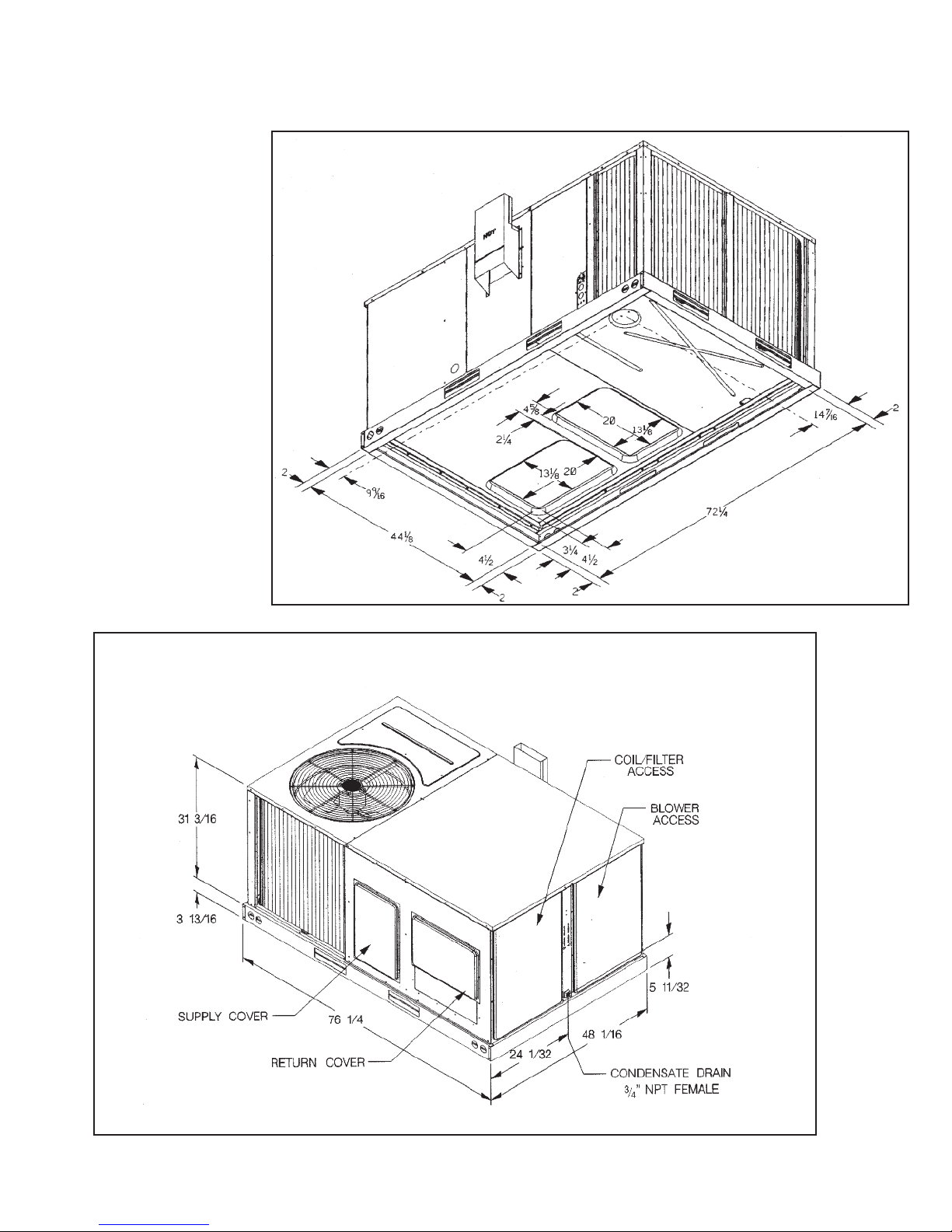
VI. UNIT DIMENSIONS
FOR CLEARANCES
SEE FIGURE 7.
IMPORTANT: THIS UNIT
MUST BE MOUNTED
LEVEL IN BOTH DIRECTIONS TO ALLOW WATER
TO DRAIN FROM THE CONDENSER SECTION AND
CONDENSATE PAN.
FIGURE 1
OTTOM VIEW
B
FIGURE 2
CABINET DIMENSIONS AND ACCESS LOCATIONS
I316
I281
5
Page 6
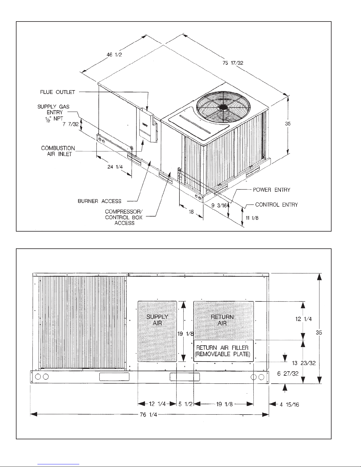
IGURE 3
F
ABINET DIMENSIONS AND ACCESS LOCATIONS
C
FIGURE 4
SUPPLY AND RETURN DIMENSIONS
I282
6
I288
Page 7
WARNING
!
NEVER TEST FOR GAS LEAKS
ITH AN OPEN FLAME. USE A
W
COMMERCIALLY AVAILABLE SOAP
SOLUTION MADE SPECIFICALLY
FOR THE DETECTION OF LEAKS
TO CHECK ALL CONNECTIONS, AS
SPECIFIED IN GAS SUPPLY AND
PIPING SECTION OF THESE
INSTRUCTIONS.
WARNING
!
ALWAYS INSTALL UNIT TO OPERATE WITHIN THE UNIT'S INTENDED TEMPERATURE-RISE RANGE
WITH A DUCT SYSTEM WHICH
HAS AN EXTERNAL STATIC PRESSURE WITHIN THE ALLOWABLE
RANGE, AS SPECIFIED IN DUCTING SECTION OF THESE INSTRUCTIONS. SEE ALSO UNIT RATING
PLATE.
WARNING
!
WHEN A UNIT IS INSTALLED SO
THAT SUPPLY DUCTS CARRY AIR
CIRCULATED BY THE UNIT TO
AREAS OUTSIDE THE SPACE CONTAINING THE UNIT, THE RETURN
AIR SHALL ALSO BE HANDLED BY
DUCT(S) SEALED TO THE UNIT
CASING AND TERMINATING OUTSIDE THE SPACE CONTAINING
THE UNIT.
VII.INSTALLATION
A. GENERAL
Install this unit in accordance with The American National Standard Z223.1-latest edition
booklet entitled “National Fuel Gas Code,” and the requirements or codes of the local
tility or other authority having jurisdiction.
u
Additional helpful publications available from the “National Fire Protection Association”
are: NFPA-90A - Installation of Air Conditioning and Ventilating Systems 1985 or latest
edition. NFPA-90B - Warm Air Heating and Air Conditioning Systems 1984.
These publications are available from:
National Fire Protection Association, Inc.
1 Batterymarch Park
Quincy, MA 02169-7471
www.nfpa.org
1. PRE-INSTALLATION CHECK-POINTS — Before attempting any installation, carefully consider the following points:
Structural strength of supporting members
(Rooftop Installation)
Clearances and provision for servicing
Power supply and wiring
Gas supply and piping
Air duct connections and sizing
Drain facilities and connections
Location for minimum noise and
vibration - away from bedroom
windows
2. LOCATION CONSIDERATIONS
The metal parts of this unit may be subject to rust or deterioration in adverse environmental conditions. This oxidation could shorten the equipment’s useful life. Salt
spray, fog or mist in seacoast areas, sulphur or chlorine from lawn watering systems,
and various chemical contaminants from industries such as paper mills and petroleum refineries are especially corrosive.
If the unit is to be installed in an area where contaminants are likely to be a
problem, give special attention to the equipment location and exposure.
1. Avoid having lawn sprinkler heads spray directly on the unit cabinet.
2. In coastal areas locate the unit on the side of the building away from the waterfront.
3. Shielding by a fence or shrubs may give some protection.
WARNING
!
DISCONNECT ALL POWER TO UNIT BEFORE STARTING MAINTENANCE.
FAILURE TO DO SO CAN CAUSE ELECTRICAL SHOCK RESULTING IN PERSONAL INJURY OR DEATH. REGULAR MAINTENANCE WILL REDUCE THE
BUILDUP OF CONTAMINANTS AND HELP TO PROTECT THE UNIT’S FINISH.
1. Frequent washing of the cabinet, fan blade and coil with fresh water will remove
most of the salt or other contaminants that build up on the unit.
2. Regular cleaning and waxing of the cabinet with a good automobile polish will provide some protection.
3. A good liquid cleaner may be used several times a year to remove matter that will
not wash off with water.
Several different types of protective coatings are offered in some areas. These coatings
may provide some benefit, but the effectiveness of such coating materials cannot be verified by the equipment manufacturer.
The best protection is frequent cleaning, maintenance and minimal exposure to
contaminants.
7
Page 8
WARNING
!
THIS UNIT MAY BE USED TO HEAT
HE BUILDING OR STRUCTURE
T
DURING CONSTRUCTION IF THE
FOLLOWING INSTALLATION
REQUIREMENTS ARE MET.
INSTALLATION MUST COMPLY
WITH ALL INSTALLATION
INSTRUCTIONS INCLUDING:
• PROPER VENT INSTALLATION;
• FURNACE OPERATING UNDER
THERMOSTATIC CONTROL;
• RETURN AIR DUCT SEALED TO
THE FURNACE;
• AIR FILTERS IN PLACE;
• SET FURNACE INPUT RATE AND
TEMPERATURE RISE PER RATING PLATE MARKING;
• MEANS OF PROVIDING OUTDOOR AIR REQUIRED FOR COMBUSTION;
• RETURN AIR TEMPERATURE
MAINTAINED BETWEEN 55°F
(13°C) AND 80°F (27°C); AND
• INSTALLATION OF EXHAUST
AND COMBUSTION AIR INLET
HOODS COMPLETED;
• CLEAN FURNACE, DUCT WORK
AND COMPONENTS UPON SUBSTANTIAL COMPLETION OF THE
CONSTRUCTION PROCESS, AND
VERIFY FURNACE OPERATING
CONDITIONS INCLUDING IGNITION, INPUT RATE, TEMPERATURE RISE AND VENTING,
ACCORDING TO THE INSTRUCTIONS.
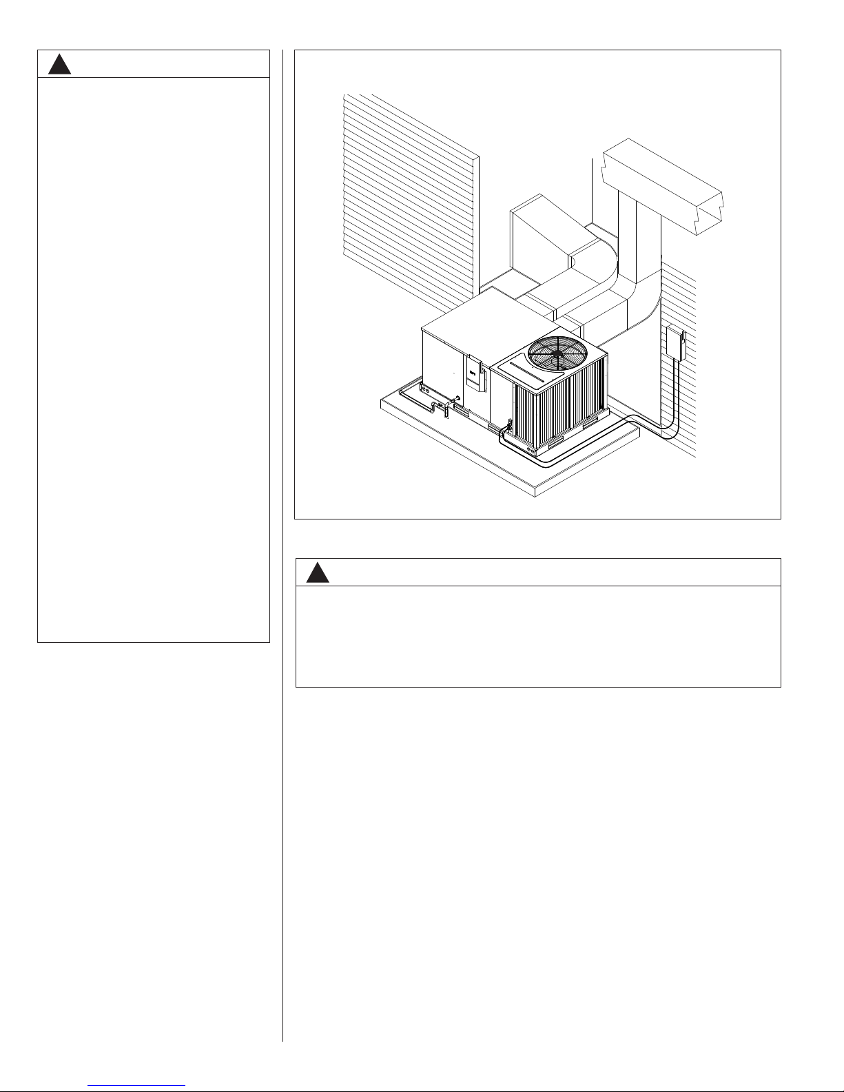
FIGURE 5
UTSIDE SLAB INSTALLATION. CLOSET DISTRIBUTION SYSTEM. SLAB FLOOR CONSTRUCTION.
O
B. OUTSIDE SLAB INSTALLATION
WARNING
!
THESE UNITS ARE DESIGNED CERTIFIED FOR OUTDOOR INSTALLATION
ONLY. INSTALLATION INSIDE ANY PART OF A STRUCTURE CAN RESULT IN
INADEQUATE UNIT PERFORMANCE AS WELL AS PROPERTY DAMAGE.
INSTALLATION INSIDE CAN ALSO CAUSE RECIRCULATION OF FLUE PRODUCTS INTO THE CONDITIONED SPACE RESULTING IN PERSONAL INJURY
OR DEATH.
I298
8
(Typical outdoor slab installation is shown in Figure 5.)
1. Select a location where external water drainage cannot collect around unit.
2. Provide a level slab sufficiently high enough above grade to prevent surface water
from entering the unit
3. The location of the unit should be such as to provide proper access for inspection
and servicing as shown in Figure 7.
4. Locate unit where operating sounds will not disturb owner or neighbors.
5. Locate unit so roof runoff water does not pour directly on the unit. Provide gutter or
other shielding at roof level. Do not locate unit in an area where excessive snow
drifting may occur or accumulate.
6. Where snowfall is anticipated, the height of the unit above the ground level must be
considered. Mount unit high enough to be above anticipated maximum area snowfall
and to allow combustion air to enter the combustion air inlet.
7. Select an area which will keep the areas of the vent, air intake, and A/C condenser
fins free and clear of obstructions such as weeds, shrubs, vines, snow, etc. Inform
the user accordingly.
8. Remove compressor shipping supports (if so equipped) after installation.
Page 9
C. ATTACHING EXHAUST AND COMBUSTION AIR INLET HOODS
IMPORTANT: Do not operate this unit without the exhaust/combustion air inlet hood
properly installed. This hood is shipped in a carton in the blower compartment inside
the unit and must be attached when the unit is installed. See Figure 3.
To attach exhaust/combustion air inlet hood:
1. Remove screws securing blower access panel and remove access panel. For location of
blower access panel, see Figure 2.
2. Remove exhaust/combustion air inlet hood from the carton, located inside the blower
compartment.
3. Attach blower access panel.
4. Attach the combustion air inlet/exhaust hood with screws. Reference Figure 3 for proper
location. Screws are in carton with the hood.
5. Vent the unit using the flue exhaust hood, as supplied from the factory, without alteration
or addition.
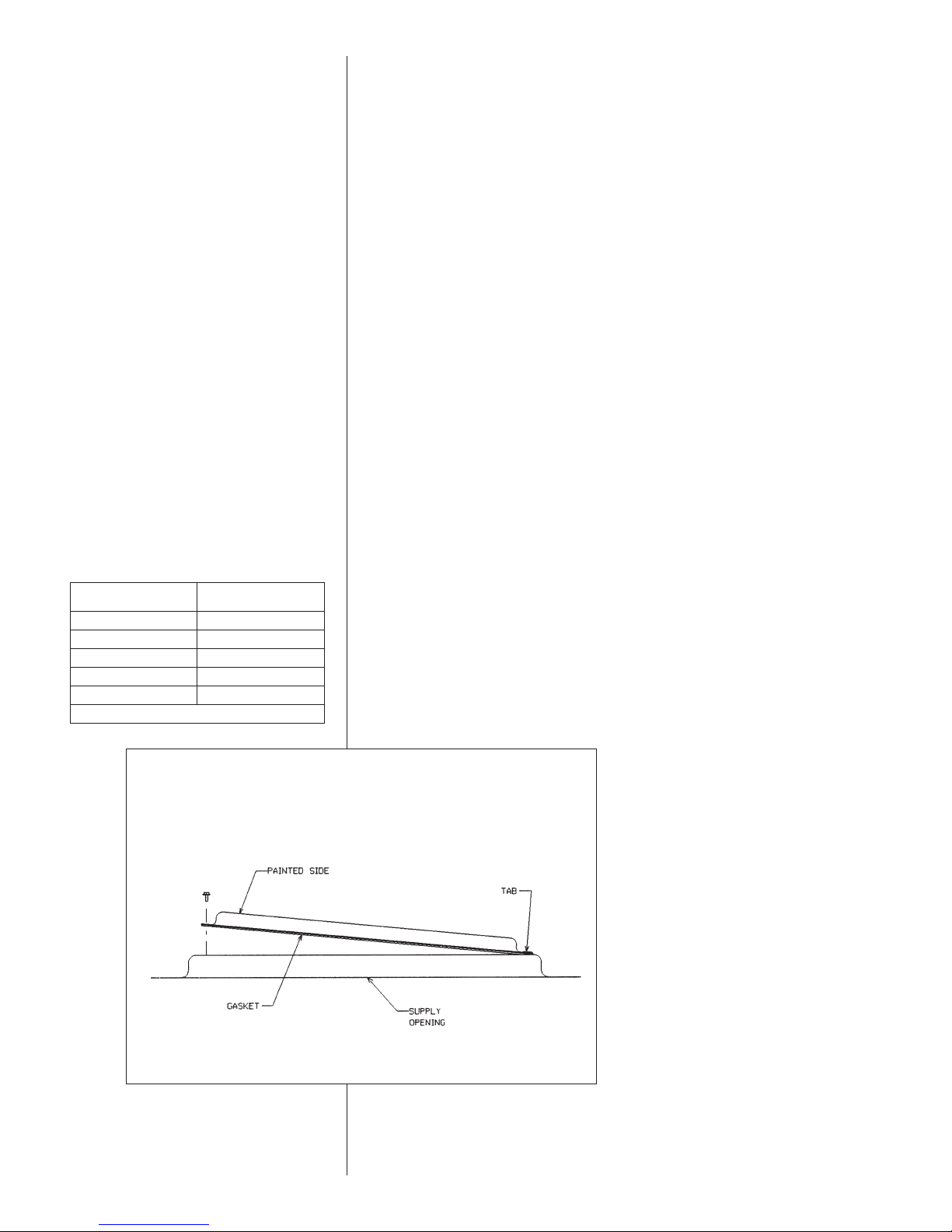
D. COVER PANEL INSTALLATION/CONVERSION PROCEDURE
DOWNFLOW TO HORIZONTAL
1. Remove the screws and covers from the outside of the supply and return sections.
2. Install the covers in the bottom supply and return openings with the painted side up.
See Figure 6. Use the existing gasket to seal the covers.
3. Secure the supply cover to the base of the unit with 1 screw, engaging prepunched
tab in unit base.
4. Secure the return cover to the base of the unit with screws engaging prepunched
holes in the unit base.
This unit is provided with 2 - 25 X 16 X 1 disposable filters. When replacing filters,
ensure they are inserted fully to the back to prevent bypass.
Recommended
Clearance
48 A - Front
18 B - Condenser Coil
12* C - Duct Side
36 D - Evaporator End
60 E - Above
*Without Economizer. 57 With Economizer
Location
FIGURE 6
COVER GASKET DETAIL FOR UNITS SHIPPED FOR DOWNFLOW APPLICATION
BEING CONVERTED TO HORIZONTAL
E. CLEARANCES
The following minimum clearances must be observed for proper unit performance and
serviceability. Reference Figure 7.
NOTE: Supply duct may be installed with “0’ inch clearance to combustible materials,
provided 1 minimum Fiberglass insulation is applied either inside or on the outside of
the duct.
I631
9
Page 10
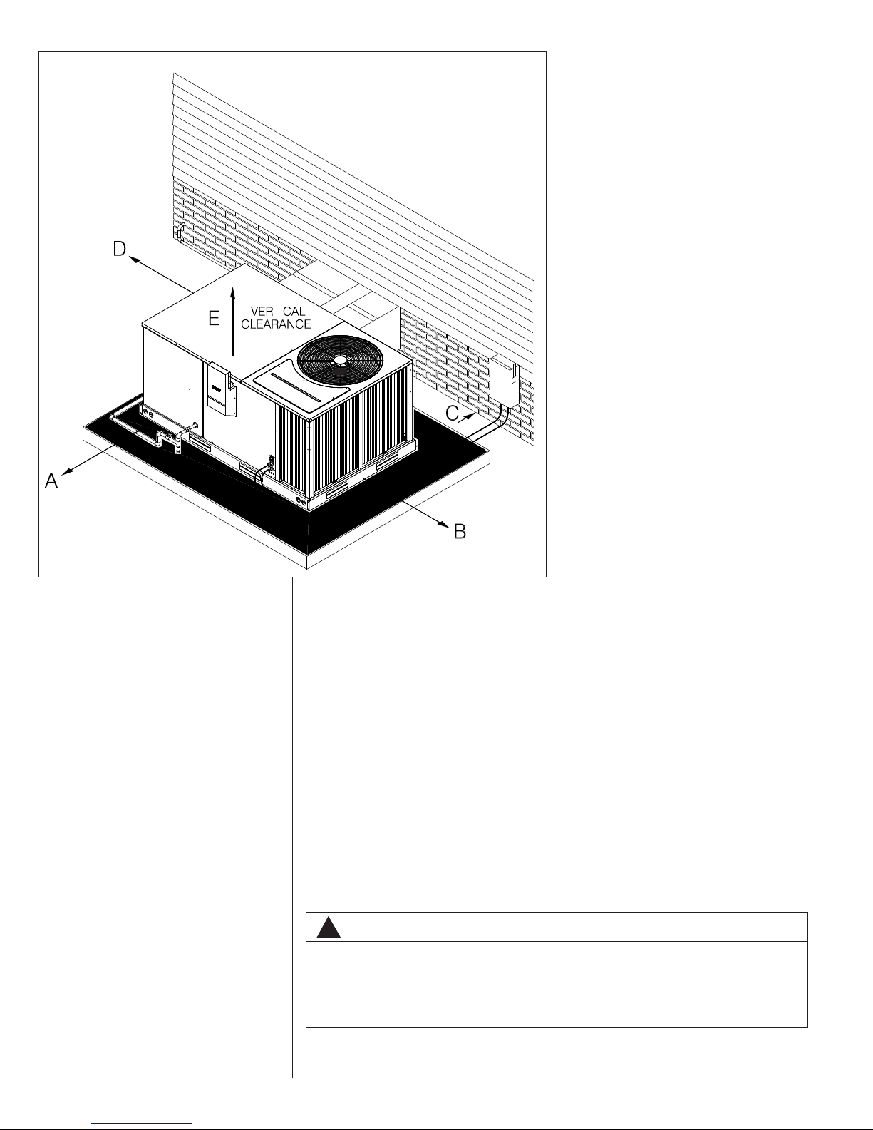
FIGURE 7
LEARANCES
C
I297
F. ROOFTOP INSTALLATION
1. Before locating the unit on the roof, make sure that the roof structure is adequate to
support the weight involved. (See Electrical & Physical Tables in this manual.) THIS
IS VERY IMPORTANT AND THE INSTALLER’S RESPONSIBILITY.
2. For rigging and roofcurb details, see Figures 8, 9, 10 and 11.
3. The location of the unit on the roof should be such as to provide proper access for
inspection and servicing.
4. Remove compressor shipping supports (if so equipped) after installation.
IMPORTANT: If unit will not be put into service immediately, block off supply and return
air openings to prevent excessive condensation.
G. DUCTWORK
The installing contractor should fabricate ductwork in accordance with local codes. Use
industry manuals as a guide when sizing and designing the duct system. Contact Air
Conditioning Contractors of America, 2800 Shirlington Road, Suite 300, Arlington, VA
22206, http://www.acca.org.
WARNING
!
DO NOT, UNDER ANY CIRCUMSTANCES, CONNECT RETURN DUCTWORK
TO ANY OTHER HEAT PRODUCING DEVICE SUCH AS FIREPLACE INSERT,
STOVE, ETC. UNAUTHORIZED USE OF SUCH DEVICES MAY RESULT IN FIRE,
CARBON MONOXIDE POISONING, EXPLOSION, PERSONAL INJURY, PROPERTY DAMAGE OR DEATH.
10
Page 11
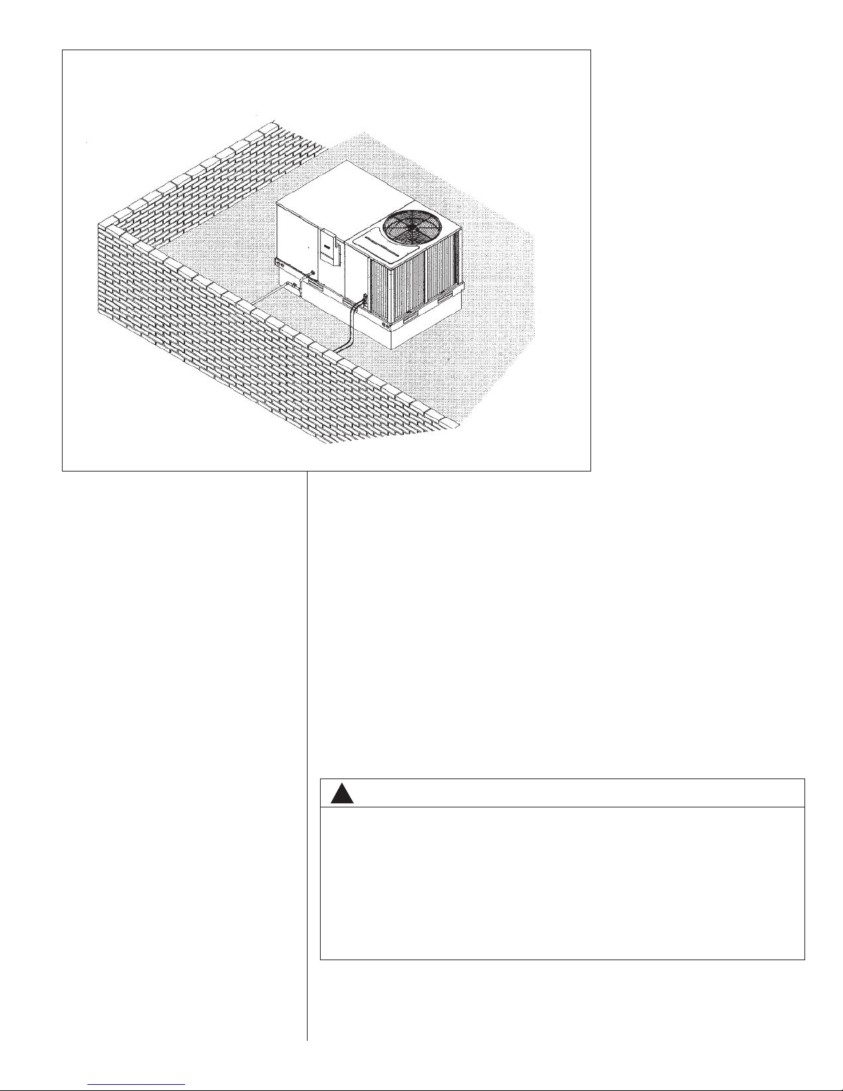
FIGURE 8
FLA T ROO FT OP IN ST ALLATION, ATTI C OR DRO P CEI LI NG DI ST RI BUTING SYSTE M. MO UN TE D ON
OOFCURB. CURB MUST BE LEVEL.
R
I299
Place the unit as close to the conditioned space as possible allowing clearances as indicated. Run ducts as directly as possible to supply and return outlets. Use of non-flammable weatherproof flexible connectors on both supply and return connections at unit to
reduce noise transmission is recommended.
On ductwork exposed to outside temperature and humidity, use a minimum of 2 of
insulation and a vapor barrier. Distribution system in attic, furred space or crawl space
should be insulated with at least 2 of insulation.
cient for ductwork inside the air conditioned space.
Provide balancing dampers for each branch duct in the supply system. Properly support
ductwork from the structure.
IMPORTANT: In the event that the return air ducts must be run through an “unconfined”
space containing other fuel burning equipment, it is imperative that the user/homeowner
must be informed against future changes in construction which might change this to a
“confined space.” Also, caution the user/homeowner against any future installation of
additional equipment (such as power ventilators, clothes dryers, etc., within the existing
unconfined and/or confined space which might create a negative pressure within the
vicinity of other solid, liquid, or gas fueled appliances.
1
⁄2 to 1 thick insulation is usually suffi-
H. RETURN AIR
WARNING
!
NEVER ALLOW PRODUCTS OF COMBUSTION OR THE FLUE PRODUCTS TO
ENTER THE RETURN AIR DUCTWORK, OR THE CIRCULATING AIR SUPPLY.
ALL RETURN DUCTWORK MUST BE ADEQUATELY SEALED AND SECURED
TO THE FURNACE WITH SHEET METAL SCREWS, AND JOINTS TAPED. ALL
OTHER DUCT JOINTS MUST BE SECURED WITH APPROVED CONNECTIONS
AND SEALED AIRTIGHT.
FAILURE TO PREVENT PRODUCTS OF COMBUSTION FROM BEING CIRCULATED INTO THE LIVING SPACE CAN CREATE POTENTIALLY HAZARDOUS
CONDITIONS, INCLUDING CARBON MONOXIDE POISONING THAT COULD
RESULT IN PERSONAL INJURY OR DEATH.
11
Page 12
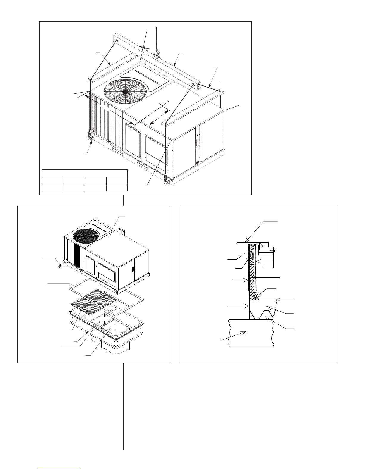
ROOFTOP UNI
COUNTER FLA
GASKET
NAILER STRIP
DUCT*
INSULATION*
CANT STRIP*
ROOF FE
INSULATI
ROOF DE
TURAL
RETURN DUCT*
SUPPLY DUCT*
NAILING STRIP
INSULATION PANELS
(2) SUPPLIED
GASKET
(FULL PERIMETER
AND ON DIVIDERS,
MUST BE ABOVE DUCT
AND INSULATION
PANEL FLANGES.)
HOLD
DOWN
BRACKET
T
YP. (4) PLCS.
U
NIT
FIGURE 9
LIFTING DETAIL
PREADER BAR
S
A
3
/8 SHACKLE
5
EACH CORNER)
(
ORNER WEIGHTS BY PERCENTAGE
C
A
22% 27% 23% 28%
BCD
B
LIFTING BEAM
ABLE OR CHAIN
C
C
.
G
8
.
2
5
C
.
2
5
.
7
5
D
296
I
FIGURE 10
ROOFCURB
SUPPLY
RETURN
ST-A0801-19-01
FIGURE 11
ROOFCURB
GASKET
NAILER STRIP
ROOFCURB
ROOF
STRUCTURAL
MEMBER*
DUCT*
*BY CONTRACTOR
ROOFTOP UNIT
COUNTER FLASHING*
INSULATION*
CANT STRIP*
ROOF FELT*
INSULATION*
ROOF DECK*
ST-A0801-19-01
12
Page 13
VIII. GAS SUPPLY, CONDENSATE DRAIN AND
VIII. PIPING
A. GAS CONNECTION
IMPORTANT: Connect this unit only to gas supplied by a commercial utility.
1. Install gas piping in accordance with local codes and regulations of the local utility
company. In the absence of local codes, the installation must conform to the specifications of the National Fuel Gas Code, ANSI Z223.1 - latest edition.
NOTE: The use of flexible gas connectors is not permitted. If local codes allow the
use of a corrugated stainless steel flexible gas appliance connector, always use a
new listed connector. Do not use a connector which has previously serviced another
gas appliance.
NOTE: The Commonwealth of Massachusetts requires the gas shut-off valve to be a
T-handle gas cock.
2. Connect the gas line to the gas pipe inlet opening provided into the 1/2 inlet valve.
See Figure 5 or 8 for typical piping.
3. Size the gas line to the furnace adequate enough to prevent undue pressure drop
and never less than 1/2 nominal pipe size.
4. Install a drip leg or sediment trap in the gas supply line as close to the unit as possible.
5. Install an outside ground joint union to connect the gas supply to the control assembly at the burner tray.
6. Gas valves have been factory installed. Install a manual gas valve where local codes
specify a shut-off valve outside the unit casing. (See Figure 13.)
7. Make sure piping is tight. A pipe compound resistant to the action of liquefied
petroleum gases must be used at all threaded pipe connections.
8. IMPORTANT: any additions, changes or conversions required for the furnace to satisfactorily meet the application should be made by a qualified installer, service
agency or the gas supplier, using factory-specified or approved parts. In the commonwealth of Massachusetts, installation must be performed by a licensed plumber
or gas fitter for appropriate fuel.
IMPORTANT: Disconnect the furnace and its individual shutoff valve from the gas supply piping during any pressure testing of that system at test pressures in excess of 1/2
pound per square inch gauge or isolate the system from the gas supply piping system
by closing its individual manual shutoff valve during any pressure testing of this gas supply system at pressures equal to or less than 1/2 PSIG.
TO CHECK FOR GAS LEAKS, USE A SOAP AND WATER SOLUTION OR OTHER
APPROVED METHOD. DO NOT USE AN OPEN FLAME.
FIGURE 13
SUGGESTED GAS PIPING
ROOF OR GROUND LEVEL INSTALLATION
FROM GAS
METER
MANUAL GAS
SHUT-OFF
VALVE
Factory supplied grommet must be utilized.
*
UNIT GAS SUPPLY
CONNECTION
WARNING
!
CHECK FOR LEAKS. THE USE OF AN OPEN FLAME CAN RESULT IN FIRE,
EXPLOSION, PROPERTY DAMAGE, PERSONAL INJURY OR DEATH.
IMPORTANT: Check the rating plate to make certain the appliance is equipped to burn
the type of gas supplied. Care should be taken after installation of this equipment that
the gas control valve not be subjected to high gas supply line pressure.
TABLE 1
NATURAL GAS PIPE CAPACITY TABLE (CU. FT./HR.)
Nominal
Iron Pipe
*
Size,
Inches
1
⁄2 132 92 73 63 56 50 46 43
3
⁄4 278 190 152 130 115 105 96 90
1 520 350 285 245 215 195 180 170
11⁄4 1,050 730 590 500 440 400 370 350
11⁄2 1,600 1,100 890 760 670 610 560 530
10 20 30 40 50 60 70 80
Equivalent Length of Pipe, Feet
13
Page 14
In making gas connections, avoid strains as they may cause noise and damage the controls. A backup wrench is required to be used on the valve to avoid damage.
The capacities of gas pipe of different diameters and lengths in cu. ft. per hr. with pressure drop of 0.3 in. and specific gravity of 0.60 (natural gas) are shown in Table 1.
After determining the pipe length, select the pipe size which will provide the minimum
cubic feet per hour required for the gas input rating of the furnace. By formula:
Gas Input of Furnace
Cu. Ft. Per Hr. Required =
The gas input of the furnace is marked on the furnace rating plate. The heating value of
the gas (BTU/FT
(BTU/HR)
eating Value of Gas
H
3
)
BTU/FT
(
3
) may be determined by consulting the local natural gas utility or the
L.P. gas supplier.
B. LP CONVERSION
WARNING
!
FACTORY FOR USE ON NATURAL GAS ONLY. CONVERSION TO LP GAS
REQUIRES A SPECIAL KIT SUPPLIED BY THE DISTRIBUTOR OR MANUFACTURER. MAILING ADDRESSES ARE LISTED ON THE FURNACE RATING PLATE,
PARTS LIST AND WARRANTY. FAILURE TO USE THE PROPER CONVERSION
KIT CAN CAUSE FIRE, CARBON MONOXIDE POISONING, EXPLOSION, PERSONAL INJURY, PROPERTY DAMAGE OR DEATH.
Convert the valve to use liquefied petroleum (LP) gas by replacing the pressure regulator
spring with the conversion kit spring. This LP kit spring allows the regulator to maintain the
proper manifold pressure for LP gas. The correct burner LP orifices are included in the kit.
See Figure 14.
IMPORTANT: To remove the gas valve, remove the four screws securing the manifold pipe
to the burner tray. Remove the manifold pipe with gas valve attached. See Figure 15.
NOTE: Order the correct LP conversion kit from the furnace manufacturer. See Conversion
Kit Index shipped with unit for proper LP kit number. Furnace conversion to LP gas
must be performed by a qualified technician.
C. NOx MODELS
When converting units equipped with NOx inserts to LP gas, the stainless steel screen
mesh inserts in the entrance of the tubular exchangers are not required to meet SCAQMD
NOx emission levels. These inserts and 1/8 diameter retaining rod should be carefully
removed before firing this furnace on LP gas. IMPORTANT: This furnace is not designed to
operate on LP gas with the NOx inserts in place.
Step by step instructions on removing the NOx inserts and retaining rod are included in the
Conversion Kit Installation Instructions.
TABLE 2
LP GAS PIPE CAPACITY TABLE (CU. FT./HR.)
Maximum capacity of pipe in thousands of BTU per hour of undiluted liquefied petroleum
gases (at 11 inches water column inlet pressure).
(Based on a Pressure Drop of 0.5 Inch Water Column)
Nominal
Iron Pipe
Size, Inches
1/2
3/4
1-1/4
1-1/2
Example (LP): Input BTU requirement of unit, 150,000
10 20 30 40 50 60 70 80 90 100 125 150
275 189 152 129 114 103 96 89 83 78 69 63
567 393 315 267 237 217 196 182 173 162 146 132
1,071 732 590 504 448 409 378 346 322 307 275 252
1
2,205 1,496 1,212 1,039 913 834 771 724 677 630 567 511
3,307 2,299 1,858 1,559 1,417 1,275 1,181 1,086 1,023 976 866 787
6,221 4,331 3,465 2,992 2,646 2,394 2,205 2,047 1,921 1,811 1,606 1,496
2
Equivalent length of pipe, 60 ft. = 3/4 IPS required.
Length of Pipe, Feet
14
Page 15
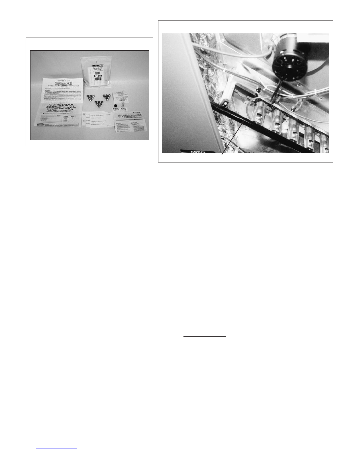
FIGURE 14
FIGURE 15
ANIFOLD PIPE
M
D. ADJUSTING OR CHECKING FURNACE INPUT
– Natural Gas Line Pressure 5- 10.5W.C.
– LP Gas Line Pressure 11
– Natural Gas Manifold Pressure 3.5
– LP Gas Manifold Pressure - 10
Supply and manifold pressure taps are located on the gas valve body 1/8 N.P.T. and on
the manifold.
Use a properly calibrated manometer gauge for accurate gas pressure readings.
Only small variations in the gas flow should be made by means of the pressure regulator
adjustment. Furnaces functioning on LP gas must be set by means of the tank or branch
supply regulators. The furnace manifold pressure should be set at 10 W.C. at the gas control valve.
To adjust the pressure regulator, remove the regulator cap and turn the adjustment screw
clockwise to increase pressure or counterclockwise to decrease pressure. Then replace
the regulator cap securely.
Any necessary major changes in the gas flow rate should be made by changing the size of
the burner orifices. To change orifice spuds, shut off the manual main gas valve and
remove the gas manifold.
For elevations up to 2,000 feet, rating plate input ratings apply. For high altitudes (elevations
over 2,000 ft.), see conversion kit index 92-21519-XX for derating and orifice spud sizes.
Check of input is important to prevent over-firing of the furnace beyond its designrated input. NEVER SET INPUT ABOVE THAT SHOWN ON THE RATING PLATE. Use
the following table or formula to determine input rate.
Cu. Ft. Per Hr. Required =
Start the furnace and measure the time required to burn one cubic foot of gas. Prior to
checking the furnace input, make certain that all other gas appliances are shut off, with
the exception of pilot burners. Time the meter with only the furnace in operation.
IMPORTANT NOTE FOR ALTITUDES ABOVE 2,000 FEET (610 METERS): The main
burner orifices in your furnace and in these kits are sized for the nameplate input and
intended for installations at elevations up to 2,000 feet in the USA or Canada, or for elevations of 2,000 - 4,500 feet (610 -1,373 meters) in Canada if the unit has been derated
at the factory. For elevations above 2,000 feet (610 meters) IN THE USA ONLY (see
ANSI-Z223.1), the burner orifices must be sized to reduce the input 4% for each 1,000
feet (305 meters) above sea level.
- 13W.C.
W.C
W.C.
Heating Value of Gas
(BTU/Cu. Ft.) x 3600
Time in Seconds
(for 1 Cu. Ft.) of Gas
15
Page 16
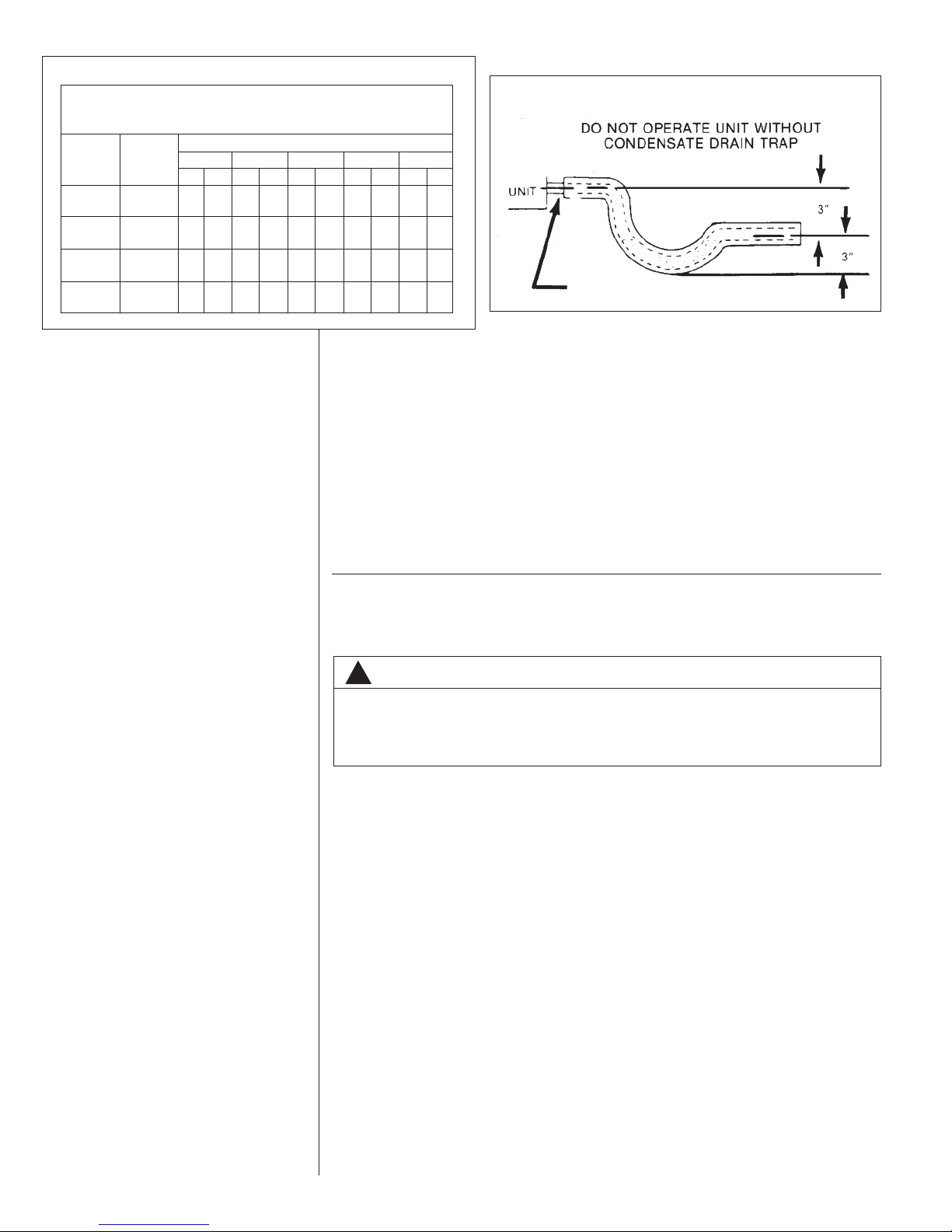
TABLE 3
INPUT
BTU/HR
40,000
60,000
80,000
100,000
METER TIME IN MINUTES AND SECONDS FOR NORMAL
INPUT RATING OF FURNACES EQUIPPED FOR NATURAL
METER
SIZE
CU. FT.
MIN. SEC. MIN. SEC. MIN. SEC. MIN. SEC. MIN. SEC.
ONE 1 21 1 30 1 34 1 39 3 45
TEN 13 30 15 0 15 36 16 30 37 30
ONE 0 54 1 01 31 6 230
TEN 9010 0 10 24 11 0 25 0
ONE 0 41 0 45 0 47 0 50 1 53
TEN 6 45 7 30 7 48 8 15 18 45
ONE 0 33 0 36 0 38 0 40 1 30
TEN 5 24 60615 6 36 15 0
OR LP GAS
HEATING VALUE OF GAS BTU PER CU. FT.
900 1000 1040 1100 2500
NOTICE: DERATING OF THE HEATING INPUT FOR HIGH ALTITUDE IN THE FIELD
IS UNLAWFUL IN CANADA (REFER TO CAN/CGA 2.17). UNITS INSTALLED IN
ALTITUDES GREATER THAN 2,000 FEET (610 METERS) MUST BE SHIPPED FROM
THE FACTORY OR FROM A FACTORY AUTHORIZED CONVERSION STATION
WITH THE HEATING INPUT DERATED BY 10% SO AS TO OPERATE PROPERLY IN
ALTITUDES FROM 2,000 - 4,500 FEET (610 - 1,373 METERS).
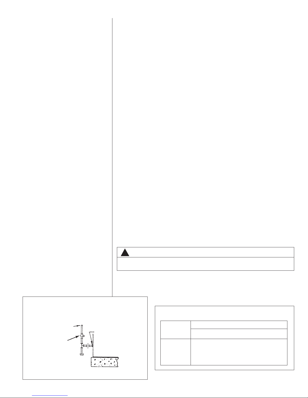
E.CONDENSATE DRAIN
The condensate drain connection of the evaporator is threaded 3/4 nominal P.V.C.
pipe. IMPORTANT: Install a condensate trap to ensure proper condensate drainage.
See Figure 16.
IGURE 16
F
ONDENSATE DRAIN
C
DO NOT OVERTIGHTEN DRAIN FITTING
IX. WIRING
A. POWER SUPPLY
WARNING
!
TURN OFF THE MAIN ELECTRICAL POWER AT THE BRANCH CIRCUIT DISCONNECT CLOSEST TO THE UNIT BEFORE ATTEMPTING ANY WIRING. FAILURE TO DO SO CAN CAUSE ELECTRICAL SHOCK RESULTING IN PERSONAL
INJURY OR DEATH.
1. All wiring should be made in accordance with the National Electrical Code.
Consult the local power company to determine the availability of sufficient power to
operate the unit. Check the voltage at power supply to make sure it corresponds to
the unit’s RATED VOLTAGE REQUIREMENT. Install a branch circuit disconnect
near the rooftop, in accordance with the N.E.C., C.E.C. or local codes. A bracket is
provided with the unit for mounting of the disconnect. See Figure 17.
2. It is important that proper electrical power is available at the unit. Voltage should not
vary more than 10% from that stamped on the unit nameplate. On three phase units,
phases must be balanced within 3%.
3. For branch circuit wiring (main power supply to unit disconnect), the minimum wire size
for the length of run can be determined from Table 3 using the circuit ampacity found on
the unit rating plate. Use the smallest wire size allowable in Table 4 from the unit disconnect to unit.
NOTE: A bracket is provided with the unit for mounting the branch circuit disconnect to
the unit. This is the recommended location for the disconnect. See Figure 17.
4. For through the base wiring entry reference Figure 18. All fittings and conduit are field
supplied for this application. Reference the chart with Figure 18 for proper hole and
conduit size.
16
Page 17
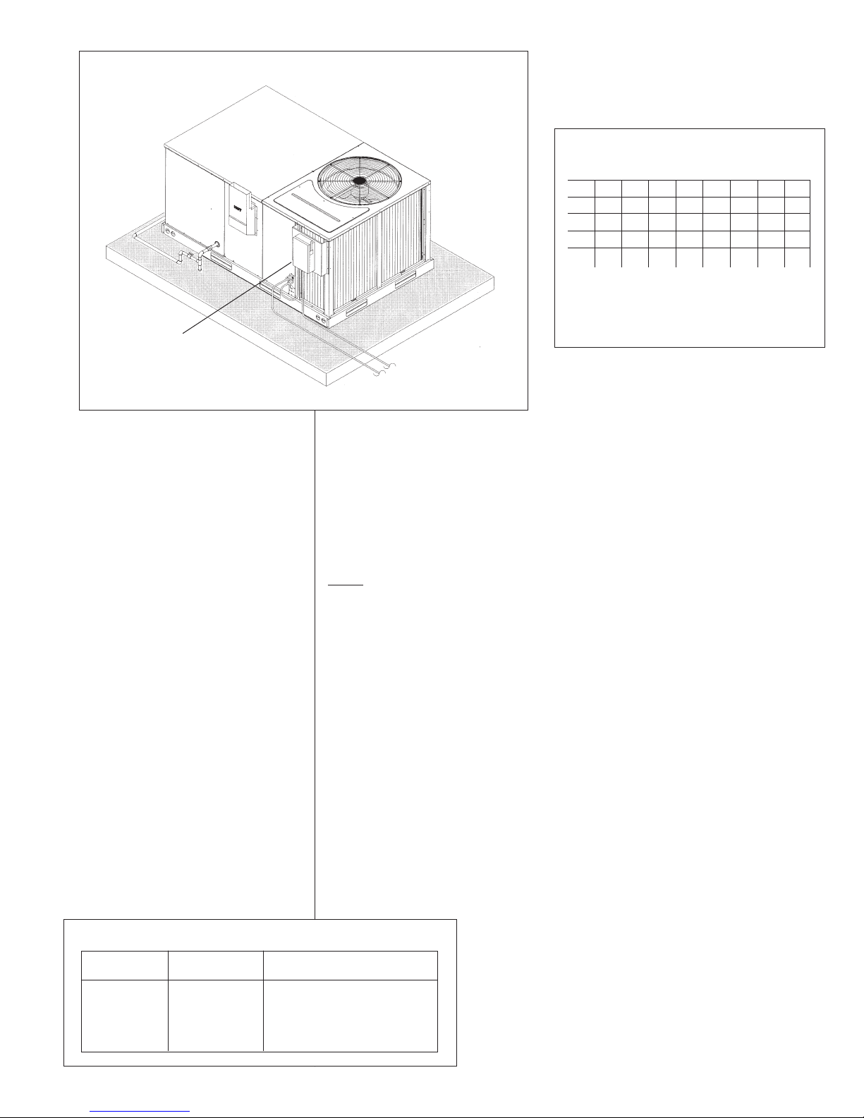
FIGURE 17
ECOMMENDED BRANCH CIRCUIT DISCONNECT LOCATION
R
BRANCH
IRCUIT
C
DISCONNECT
NOTES:
1. Wire size based on 60°C rated wire insulation and 30°C Ambient Temp. (86°F).
2. For more than 3 conductors in a raceway or cable, see the N.E.C. for derating the
ampacity of each conductor.
When installed, the unit must be electrically grounded in accordance with local
codes or, in the absence of local codes, with the National Electrical Code,
ANSI/NFPA 70, if an external electrical source is utilized.
IMPORTANT: THIS UNIT IS AP PROVED FOR USE WITH COPPER CONDUCTORS
ONLY
WARRANTY MAY BE JEOPARDIZED IF ALUMINUM WIRE IS CONNECTED TO
UNIT CONTACTOR.
Special instructions apply for power wiring with aluminum conductors: Warranty
is void if connections are not made per instructions.
Attach a length (6 or more) of recommended size copper wire to the unit contactor terminals L1 and L3 for single phase, L1, L2 and L3 for three phase.
Select the equivalent aluminum wire size from the tabulation below:
Splice copper wire pigtails to aluminum wire with U.L. recognized connectors for copperaluminum splices. Please exercise the following instructions very carefully to obtain a
positive and lasting connection:
1. Strip insulation from aluminum conductor.
2. Coat the stripped end of the aluminum wire with the recommended inhibitor, and
wire brush the aluminum surface through inhibitor. INHIBITORS: Brundy-Pentex “A”;
Alcoa-No. 2EJC; T & B-KPOR Shield.
3. Clean and recoat aluminum conductor with inhibitor.
4. Make the splice using the above listed wire nuts or split bolt connectors.
5. Coat the entire connection with inhibitor and wrap with electrical insulating tape.
O POWER
T
O THERMOSTAT
T
I317A
CONNECTED TO UNIT CONTACTOR.
TABLE 4
RANCH CIRCUIT COPPER WIRE SIZE
B
Based on 1% Voltage Drop)*
(
200 64443322
150 86644433
100 10 8866644
50 14 12 10 10 8866
15 20 25 30 35 40 45 50
BRANCH CIRCUIT AMPACITY
SUPPLY WIRE
LENGTH-FEET
*Taken from National Electric Code
TABLE 5
AWG Copper AWG Aluminum Connector Type and Size
Wire Size Wire Size (or equivalent)
#12 #10 T & B Wire Nut PT2
#10 # 8 T & B Wire Nut PT3
# 8 # 6 Sherman Split Bolt TSP6
# 6 # 4 Sherman Split Bolt TSP4
# 4 # 2 Sherman Split Bolt TSP2
17
Page 18
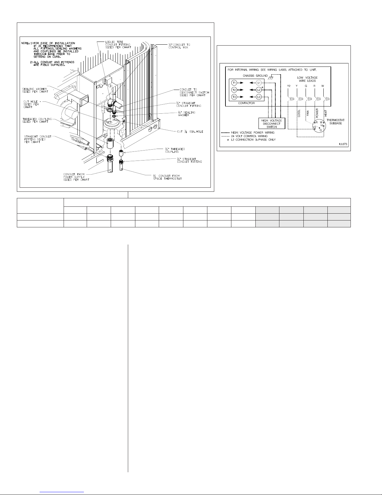
FIGURE 18
FIGURE 19
TYPICAL THERMOSTAT WIRING
I658
WIRE SIZE, AWG
14
CONDUIT SIZE
HOLE SIZE
NOTES: 1. DETERMINE REQUIRED WIRE SIZE FROM MINIMUM CIRCUIT AMPACITY SHOWN IN INSTALLATION & OPERATING INSTRUCTION.
2. BOTTOM POWER ENTRY WILL NOT ACCOMMODATE WIRE LARGER THAN #2 AWG (SHADED AREA).
1/2
7/8
12
1/2
7/8
10
1/2
7/8
8
3/4
1-31/32
6
1
1-23/64
4
1
1-23/64
3
1-1/4
1-23/32
2
1-1/4
1-23/32
1
1-1/2
1-31/32
0
1-1/2
1-31/32
2-15/32
00
000
2
2
2-15/32
B. HOOK-UP
To wire unit, refer to the following hook-up diagram.
Refer to Figures 3 and 18 for location of wiring entrances.
Wiring to be done in the field between the unit and devices not attached to the unit, or
between separate devices which are field installed and located, shall conform with the
temperature limitation for Type T wire [63°F rise (35°C)] when installed in accordance
with the manufacturer’s instructions.
C. INTERNAL WIRING
IMPORTANT: Some single phase units are equipped with a single pole contactor.
Caution must be exercised when servicing as only one leg of the power supply is broken
with the contactor.
Some models are equipped with electronically commutated blower motors which are
constantly energized, unless the main unit disconnect is in the off position.
A diagram of the internal wiring of this unit is located under the electrical box cover and
this manual. If any of the original wire as supplied with the appliance must be replaced,
the wire gauge and insulation must be same as original wiring.
Transformer is factory wired for 230 volts on 208/230 volt models and must be changed
for 208 volt applications. See unit wiring diagram for 208 volt wiring.
D. THERMOSTAT
The room thermostat must be compatible with the spark ignition control on the unit.
Generally, all thermostats that are not of the “current robbing” type are compatible with
the integrated furnace control. The low voltage wiring should be sized as shown in Table
6.
Install the room thermostat in accordance with the instruction sheet packed in the box
with the thermostat. Run the thermostat lead wires inside the compressor access panel
compartment and connect to low voltage terminals as shown on the wiring diagram.
Never install the thermostat on an outside wall or where it will be influenced by drafts,
concealed hot or cold water pipes or ducts, lighting fixtures, radiation from fireplace, sun
18
Page 19
TABLE 6
FIELD WIRE SIZE FOR 24 VOLT THERMOSTAT CIRCUITS
SOLID COPPER WIRE - AWG.
3.0 16 14 12 10 10 10
2.5 16 14 12 12 12 10
2.0 18 16 14 12 12 10
Amps
Thermostat Load -
(1) The total wire length is the distance from the furnace to the thermostat and back to the furnace.
NOTE: DO NOT USE CONTROL WIRING SMALLER THAN NO. 18
AWG.
50 100 150 200 250 300
Length of Run – Feet (1)
rays, lamps, televisions, radios or air streams from registers. Refer to instructions
packed with the thermostat for “heater” selection or adjustment.
The following are the recommended thermostats available through the manufacturer to
be used:
W/O Economizer W/Economizer
(-)HC-TST101GESS (-)HC-TST103UNMS
(-)HC-TST103UNMS (-)HC-TST203UNMS
(-)HC-TST201GESS (-)HC-TST302UNMS
(-)HC-TST203UNMS (-)HC-TST303UNMS
(-)HC-TST301GESS (-)HC-TST304UNMS
(-)HC-TST302UNMS
(-)HC-TST303UNMS
(-)HC-TST304UNMS
X. FURNACE SECTION CONTROLS AND
IGNITION SYSTEM
NORMAL FURNACE OPERATING SEQUENCE
This unit is equipped with an integrated direct spark ignition control.
1. The thermostat calls for heat.
2. The control board will run a self check to verify that the limit control and manual reset
overtemperature control are closed and that the pressure switch is open.
3. Upon closure of the pressure switch, the control board energizes the induced draft
blower for a 15 second prepurge.
4. After the 15 second prepurge, the gas valve opens and the spark is initiated for 7 second trial for ignition.
5. Burners ignite and flame sensor proves all burners have lit.
6. The circulating air blower is energized after 30 seconds.
7. The control board enters a normal operation loop in which all safety controls are monitored continuously.
8. Thermostat is satisfied and opens.
9. The gas valve is de-energized and closes, shutting down the burner flame.
10. The control board will de-energize the inducer after a five second post purge.
11. The circulating air blower is de-energized after 90 seconds.
The integrated control is a three ignition system.
After a total of three cycles without sensing main burner flame, the system goes into a
100% lockout mode. After one hour, the ignition control repeats the prepurge and ignition
cycles for 3 tries and then go into 100% lockout mode again. It continues this sequence of
cycles and lockout each hour until ignition is successful or power is interrupted. During the
lockout mode, neither the ignitor or gas valve will be energized until the system is reset by
turning the thermostat to the “OFF” position or interrupting the electrical power to the unit
for 3 seconds or longer. The induced draft blower and main burner will shut off when the
thermostat is satisfied.
The circulating air blower will start and run on the heating speed if the thermostat fan
switch is in the “ON” position.
The integrated furnace control is equipped with diagnostic LED. The LED is lit continuously
when there is power to the control, with or without a call for heat. If the LED is not lit, there
19
Page 20
is either no power to the control or there is an internal component failure within the control,
and the control should be replaced.
If the control detects the following failures, the LED will flash on for approximately 1/4 second, then off for 3/4 second for designated failure detections.
1 Flash: Failed to detect flame within the three tries for ignition.
2 Flash: Pressure switch or induced draft blower problem detected.
3 Flash: High limit or auxiliary limit open.
4 Flash: Flame sensed and gas valve not energized or flame sensed with no “W” signal.
5 Flash: Overtemperature switch open.
OPERATING INSTRUCTIONS
This appliance is equipped with integrated furnace control. This device lights the main
burners each time the room thermostat (closes) calls for heat. See operating instructions
on the back of the furnace/controls access panel.
WARNING
!
DO NOT ATTEMPT TO MANUALLY LIGHT THIS FURNACE WITH A MATCH OR
ANY OPEN FLAME. ATTEMPTING TO DO SO CAN CAUSE AN EXPLOSION OR
FIRE RESULTING IN PROPERTY DAMAGE, PERSONAL INJURY OR DEATH.
TO START THE FURNACE
1. STOP! Read the safety information on the Operating Instructions label located on this
appliance.
WARNING
!
IF YOU DO NOT FOLLOW THESE INSTRUCTIONS EXACTLY, A FIRE OR EXPLOSION MAY RESULT CAUSING PROPERTY DAMAGE, PERSONAL INJURY OR
LOSS OF LIFE.
2. Set the thermostat to its lowest setting.
3. Turn off all electric power to the appliance.
4. This appliance does not have a pilot. It is equipped with an ignition device which automatically lights the burner. Do NOT
5. Remove control door/access panel.
6. Move switch to the “OFF” position.
7. Wait five (5) minutes to clear out any gas. Then smell for gas, including near the floor.
If you smell gas, STOP!
• Do not try to light any appliance.
• Do not touch any electric switch; do not use any phone in your building.
• Immediately call your gas supplier from a neighbor’s phone. Follow the gas supplier’s instructions.
• If you cannot reach your gas supplier, call the fire department.
If you don’t smell gas, go to the next step.
8. Move “OFF” position to “ON” position.
9. Replace the control door.
10. Turn on all electric power to the appliance.
11. Set the thermostat to the desired setting.
12. If the appliance will not operate, follow the instructions below on how to shut down the
furnace.
WARNING
!
THE SPARK IGNITOR AND IGNITION LEAD FROM THE IGNITION CONTROL
ARE HIGH VOLTAGE. KEEP HANDS OR TOOLS AWAY TO PREVENT ELECTRICAL SHOCK. SHUT OFF ELECTRICAL POWER BEFORE SERVICING ANY OF
THE CONTROLS. FAILURE TO ADHERE TO THIS WARNING CAN RESULT IN
PERSONAL INJURY OR DEATH.
try to light the burner by hand.
20
The initial start-up on a new installation may require the control system to be energized for
some time until air has bled through the system and fuel gas is available at the burners.
TO SHUT DOWN FURNACE
1. Set the thermostat to the lowest setting.
2. Turn off all electric power to the appliance if service is to be performed.
3. Remove control door.
4. Move switch to the “OFF” position.
5. Replace control door.
Page 21
WARNING
!
SHOULD OVERHEATING OCCUR OR THE GAS SUPPLY FAIL TO SHUT OFF,
SHUT OFF THE MANUAL GAS VALVE TO THE APPLIANCE BEFORE SHUTTING
FF THE ELECTRICAL SUPPLY. FAILURE TO DO SO CAN RESULT IN AN
O
EXPLOSION OR FIRE CAUSING PROPERTY DAMAGE, SEVERE PERSONAL
INJURY OR DEATH!
BURNERS
urners for these units have been designed so that field adjustment is not required.
B
Burners are tray-mounted and accessible for easy cleaning when required.
MANUAL RESET OVERTEMPERATURE CONTROL
Two manual reset overtemperature controls (one on 80,000 BTUH) are located on the
burner shield. These devices senses blockage in the heat exchanger or insufficient combustion air. This shuts off the main burners if excessive temperatures occur in the burner
compartment.
Operation of this control indicates an abnormal condition. Therefore, the unit should be
examined by a qualified installer, service agency, or the gas supplier before being placed
back into operation.
WARNING
!
DO NOT JUMPER THIS DEVICE! DO NOT reset the over temperature control
without taking corrective action to assure that an adequate supply of combustion air is maintained under all conditions of operation. Failure to do so can
result in carbon monoxide poisoning or death. Replace this control only with the
identical replacement part.
PRESSURE SWITCH
This furnace has a pressure switch for sensing a blocked exhaust or a failed induced draft
blower. It is normally open and closes when the induced draft blower starts, indicating air
flow through the combustion chamber.
LIMIT CONTROL
The supply air high temperature limit cut-off is set at the factory and cannot be adjusted. It
is calibrated to prevent the air temperature leaving the furnace from exceeding the maximum outlet air temperature.
WARNING
!
DO NOT JUMPER THIS DEVICE! DOING SO CAN CAUSE A FIRE OR EXPLOSION
RESULTING IN PROPERTY DAMAGE, PERSONAL INJURY OR DEATH.
IMPORTANT: Replace this control only with the identical replacement part.
XI. SYSTEM OPERATING INFORMATION
ADVISE THE CUSTOMER
1. Change the air filters regularly. The heating system operates better, more efficiently
and more economically.
2. Arrange the furniture and drapes so that the supply air registers and the return air
grilles are unobstructed.
3. Close doors and windows. This reduces the heating and cooling load on the system.
4. Avoid excessive use of exhaust fans.
5. Do not permit the heat generated by television, lamps or radios to influence the thermostat operation.
6. Except for the mounting platform, keep all combustible articles three feet from the unit
and exhaust system.
21
Page 22
7. IMPORTANT: Replace all blower doors and compartment cover after servicing the
unit. Do not operate the unit without all panels and doors securely in place.
8. Do not allow snow or other debris to accumulate in the vicinity of the appliance.
FURNACE SECTION MAINTENANCE
The unit’s furnace should operate for many years without excessive scale build-up in flue
passageways; however, it is recommended that a qualified installer, service agency, or the
gas supplier annually inspect the flue passageways, the exhaust system and the burners
or continued safe operation, paying particular attention to deterioration from corrosion or
f
other sources.
If during inspection the flue passageways and exhaust system are determined to require
cleaning, the following procedures should be followed (by a qualified installer, service
agency, or gas supplier):
1. Turn off the electrical power to the unit and set the thermostat to the lowest
temperature.
2. Shut off the gas supply to the unit either at the meter or at manual valve in the
supply piping.
WARNING
!
LABEL ALL WIRES PRIOR TO DISCONNECTION WHEN SERVICING CONTROLS.
WIRING ERRORS CAN CAUSE IMPROPER AND DANGEROUS OPERATION
RESULTING IN FIRE, ELECTRICAL SHOCK, PROPERTY DAMAGE, PERSONAL
INJURY OR DEATH.
3. Remove the furnace controls access panel and the control box cover.
4. Disconnect the gas supply piping from the gas valve.
5. Disconnect the wiring to the induced draft blower motor, gas valve, flame sensor, and
flame roll-out control, and ignitor cable. Mark all wires disconnected for proper
reconnection.
6. Remove the screws (4) connecting the burner tray to the heat exchanger mounting
panel.
7. Remove the burner tray and the manifold assembly from the unit.
8. Remove the screws (5) connecting the induced draft blower to the collector box and
screws (18) connecting the collector box to the heat exchanger center panel. Remove
the induced draft blower and the collector box from the unit.
9. Remove the screws (3) connecting the divider plate to the heat exchanger center
panel.
10. Remove the turbulators from inside the heat exchangers by inserting the blade of a
screwdriver under the locking tabs. Pop the tabs out of the expanded grooves of the
heat exchanger. Slide the turbulators out of the heat exchangers.
11. Direct a water hose into the outlet of the heat exchanger top. Flush the inside of each
heat exchanger tube with water. Blow out each tube with air to remove excessive
moisture.
12. Reassemble (steps 1 through 10 in reverse order). Be careful not to strip out the
screw holes used to mount the collector box and inducer blower. Replace
inducer blower gasket and collector box gasket with factory replacements if
damaged.
22
WARNING
!
HOLES IN THE EXHAUST TRANSITION OR HEAT EXCHANGER CAN CAUSE
TOXIC FUMES TO ENTER THE HOME. THE EXHAUST TRANSITION OR HEAT
EXCHANGER MUST BE REPLACED IF THEY HAVE HOLES OR CRACKS IN
THEM. FAILURE TO DO SO CAN CAUSE CARBON MONOXIDE POISONING
RESULTING IN PERSONAL INJURY OR DEATH.
The manufacturer recommends that a qualified installer, service agency or the gas supplier visually inspect the burner flames for the desired flame appearance at the beginning of
the heating season and approximately midway in heating season.
The manufacturer also recommends that a qualified installer, service agency or the gas
supplier clean the flame sensor with steel wool at the beginning of the heating season.
Page 23

WARNING
!
DISCONNECT MAIN ELECTRICAL POWER TO THE UNIT BEFORE ATTEMPTING MAINTENANCE. FAILURE TO DO SO MAY RESULT IN ELECTRICAL
HOCK OR SEVERE PERSONAL INJURY OR DEATH.
S
LUBRICATION
IMPORTANT: DO NOT attempt to lubricate the bearings on the blower motor or the
nduced draft blower motor. Addition of lubricants can reduce the motor life and void the
i
warranty.
The blower motor and induced draft blower motor are prelubricated by the manufacturer
and do not require further attention.
A qualified installer, service agency or the gas supplier must periodically clean the
motors to prevent the possibility of overheating due to an accumulation of dust and dirt
on the windings or on the motor exterior. And, as suggested elsewhere in these instructions, the air filters should be kept clean because dirty filters can restrict air flow and the
motor depends upon sufficient air flowing across and through it to prevent overheating.
COOLING SECTION MAINTENANCE
WARNING
!
DISCONNECT MAIN ELECTRICAL POWER TO THE UNIT BEFORE ATTEMPTING MAINTENANCE. FAILURE TO DO SO CAN CAUSE ELECTRICAL SHOCK
RESULTING IN SEVERE PERSONAL INJURY OR DEATH.
It is recommended that at the beginning of each cooling season a qualified installer or
service agency inspect and clean the cooling section of this unit. The following areas
should be addressed: evaporator coil. condenser coil, condenser fan motor and venturi
area.
To inspect the evaporator coil:
1. Remove the filter access panel and the blower/evaporator coil access panel.
Remove the filters.
WARNING
!
LABEL ALL WIRES PRIOR TO DISCONNECTION WHEN SERVICING THE UNIT.
WIRING ERRORS CAN CAUSE IMPROPER AND DANGEROUS OPERATION
RESULTING IN FIRE, ELECTRICAL SHOCK, PROPERTY DAMAGE, SEVERE
PERSONAL INJURY OR DEATH.
2. Shine a flashlight on the evaporator coil (both sides) and inspect for accumulation of
lint, insulation, etc.
3. If coil requires cleaning, follow the steps shown below.
Cleaning Evaporator Coil
1. The coil should be cleaned when it is dry. If the coil is coated with dirt or lint, vacuum
it with a soft brush attachment. Be careful not to bend the coil fins.
2. If the coil is coated with oil or grease, clean it with a mild detergent-and-water solution. Rinse the coil thoroughly with water. IMPORTANT: Do not
water pressure. Excessive water pressure can bend the fins and tubing of the coil
and lead to inadequate unit performance. Be careful not to splash water excessively
into unit.
3. Inspect the drain pan and condensate drain at the same time the evaporator coil is
checked. Clean the drain pan by flushing with water and removing any matters of
obstructions which may be present.
4. Go to next section for cleaning the condenser coil.
Cleaning Condenser Coil, Condenser Fan, Circulation Air Blower and Venturi
1. Remove the compressor access panel. Disconnect the wires to the condenser fan
motor in the control box (see wiring diagram). Remove the wires from the opening in
the bottom of the control box.
2. Remove the screws securing the condenser top panel and remove the panel with
condenser fan motor and grille attached.
3. The coil should be cleaned when it is dry. If the coil is coated with dirt or lint, vacuum
it with a soft brush attachment. Be careful not to bend the coil fins.
use excessive
23
Page 24

4. If the coil is coated with oil or grease, clean it with a mild detergent-and-water solution. Rinse the coil thoroughly with water. IMPORTANT: Do not
water pressure. Excessive water pressure can bend the fins and tubing of the coil
and lead to inadequate unit performance. Be careful not to splash water excessively
nto unit.
i
. The venturi should also be inspected for items of obstruction such as collections of
5
grass, dirt or spider webs. Remove any that are present.
6. Inspect the circulating air blower wheel and motor for accumulation of lint, dirt or
other obstruction and clean it necessary. Inspect the blower motor mounts and the
blower housing for loose mounts or other damage. Repair or replace if necessary.
Re-assembly
1. Place the condenser top panel back on the unit and replace all screws.
2. Run the fan motor wires through the hole in the bottom of the control box. Reconnect
fan motor wires per the wiring diagram attached to the back of the cover.
3. Replace the filter and blower/evaporator coil access panels.
4. Replace the control box cover and controls access panel.
5. Restore electrical power to the unit and check for proper operation, especially the
condenser fan motor.
use excessive
REPLACEMENT PARTS
Contact your local distributor for a complete parts list.
TROUBLESHOOTING
Refer to Troubleshooting Chart included in this manual.
WIRING DIAGRAMS
Refer to the appropriate wiring diagram included in this manual.
CHARGING
Refer to the appropriate charge chart included in this manual.
BLOWER MOTOR SPEED TAPS
After determining necessary CFM and speed tap data from the Airflow Performance
Data, follow the steps below to change speeds.
1. Remove the blower access panel.
2. Reference Figure 20 for location of the speed tap block on the blower.
3. Remove the furnace control access panel.
4. Remove the control box cover. See Figure 21 for location of the integrated furnace
control board.
5. Reference Figure 22 for the proper location of the red and black wires on the speed
tap block and on the furnace integrated control board to obtain the speed tap you
have chosen.
6. After adjusting the wires accordingly, attach the control box cover, furnace control
access panel and the blower access panel to the unit.
24
Page 25
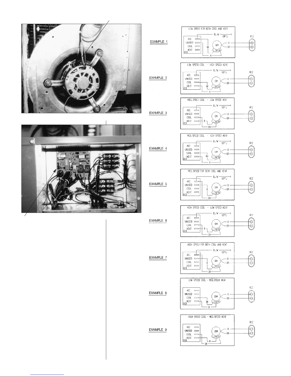
FIGURE 20
PEED TAP BLOCK
S
FIGURE 22
INTEGRATED FURNACE
CONTROL
FIGURE 21
25
Page 26
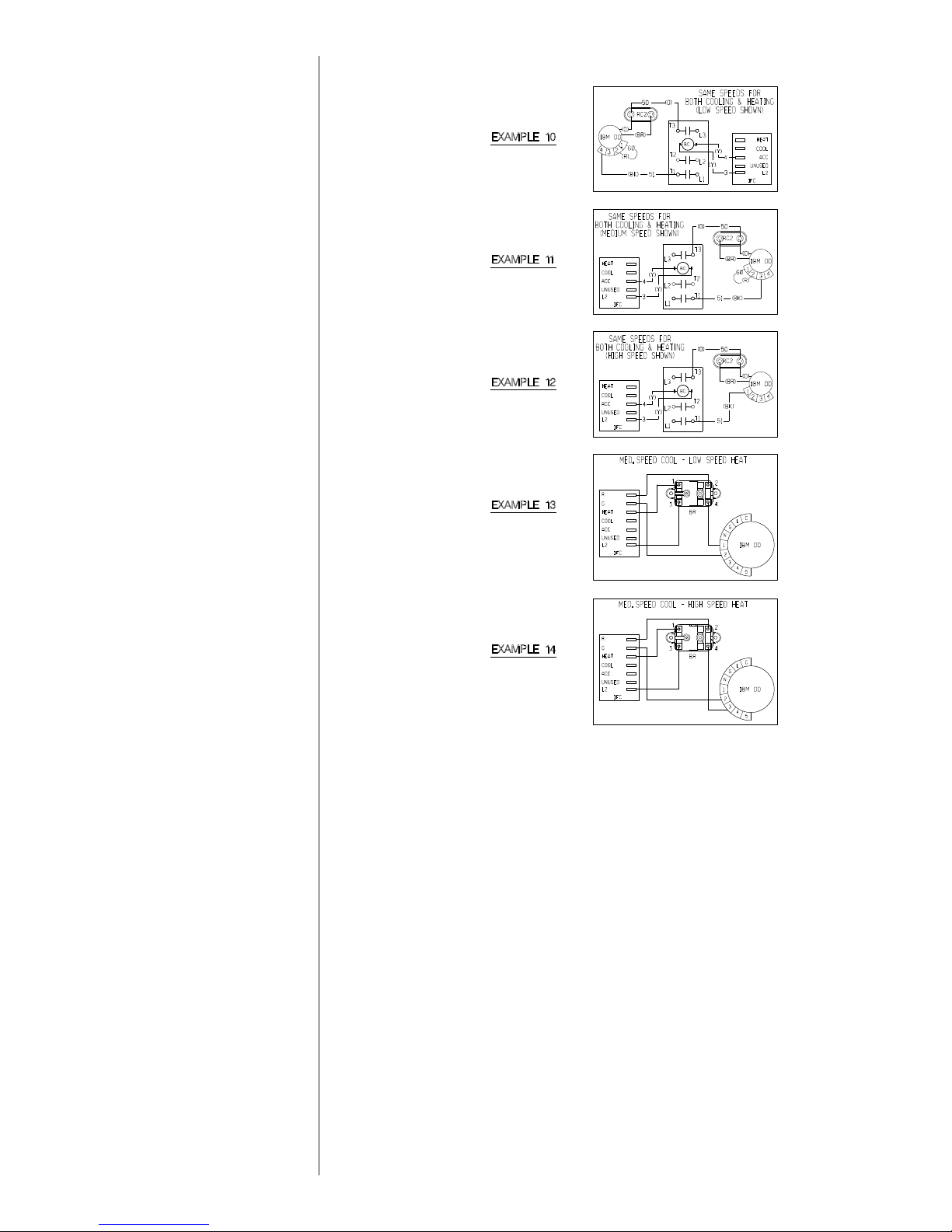
FIGURE 22 (Continued)
26
Page 27

XII. GENERAL DATA - RKNL MODELS
M
odel RKNL- Series A036CK0
8
A
036CK1
2
A
036CL0
8
A
036CL1
2
Cooling Performance
1
C
ontinued ->
Gross Cooling Capacity Btu [kW] 36,800 [10.78] 36,800 [10.78] 36,800 [10.78] 36,800 [10.78]
EER/SEER
2
1
1.4/13 11.4/13 11.4/13 11.4/13
Nominal CFM/AHRI Rated CFM [L/s] 1200/1200 [566/566
]
1200/1200 [566/566
]
1200/1200 [566/566
]
1200/1200 [566/566
]
AHRI Net Cooling Capacity Btu [kW] 35,400 [10.37] 35,400 [10.37] 35,400 [10.37] 35,400 [10.37]
Net Sensible Capacity Btu [kW] 26,200 [7.68] 26,200 [7.68] 26,200 [7.68] 26,200 [7.68]
Net Latent Capacity Btu [kW] 9,200 [2.7] 9,200 [2.7] 9,200 [2.7] 9,200 [2.7]
Net System Power kW 3.1 3.1 3.1 3.1
H
eating Performance (Gas)
4
Heating Input Btu [kW] 80,000 [23.44] 120,000 [35.16] 80,000 [23.44] 120,000 [35.16]
Heating Output Btu [kW] 64,800 [18.99] 97,200 [28.48] 64,800 [18.99] 97,200 [28.48]
Temperature Rise Range ºF [ºC] 30-60 [16.7/33.3] 50-80 [27.8/44.4] 30-60 [16.7/33.3] 50-80 [27.8/44.4]
AFUE % 80 80 80 80
Steady State Efficiency (%) 81 81 81 81
No. Burner
s
4646
No. Stages 1 1 1 1
Gas Connection Pipe Size in. [mm] 0.5 [12.7] 0.5 [12.7] 0.5 [12.7] 0.5 [12.7]
Compressor
No./Type 1/Scroll 1/Scroll 1/Scroll 1/Scroll
Outdoor Sound Rating (dB)
5
78 78 78 78
Outdoor Coil - Fin Type Louvered Louvered Louvered Louvered
Tube Type Rifled Rifled Rifled Rifled
Tube Size in. [mm] O
D
0.375 [9.5] 0.375 [9.5] 0.375 [9.5] 0.375 [9.5]
Face Area sq. ft. [sq. m] 16.91 [1.57] 16.91 [1.57] 16.91 [1.57] 16.91 [1.57]
Rows / FPI [FPcm] 1 / 22 [9] 1 / 22 [9] 1 / 22 [9] 1 / 22 [9]
Indoor Coil - Fin Type Corrugated Corrugated Corrugated Corrugated
Tube Type Rifled Rifled Rifled Rifled
Tube Size in. [mm] 0.375 [9.5] 0.375 [9.5] 0.375 [9.5] 0.375 [9.5]
Face Area sq. ft. [sq. m] 5.17 [0.48] 5.17 [0.48] 5.17 [0.48] 5.17 [0.48]
Rows / FPI [FPcm] 2 / 17 [7] 2 / 17 [7] 2 / 17 [7] 2 / 17 [7]
Refrigerant Control TX Valves TX Valves TX Valves TX Valves
Drain Connection No./Size in. [mm
]
1/0.75 [19.05] 1/0.75 [19.05] 1/0.75 [19.05] 1/0.75 [19.05]
Outdoor Fan - Type Propelle
r
Propelle
r
Propelle
r
Propelle
r
No. Used/Diameter in. [mm] 1/24 [609.6] 1/24 [609.6] 1/24 [609.6] 1/24 [609.6]
Drive Type/No. Speeds Direct/1 Direct/1 Direct/1 Direct/1
CFM [L/s] 3680 [1737] 3680 [1737] 3680 [1737] 3680 [1737]
No. Motors/HP 1 at 1/3 HP 1 at 1/3 HP 1 at 1/3 HP 1 at 1/3 HP
Motor RPM 1075 1075 1075 1075
Indoor Fan - Type FC Centrifugal FC Centrifugal FC Centrifugal FC Centrifugal
No. Used/Diameter in. [mm] 1/10x10 [254x254] 1/10x10 [254x254] 1/10x10 [254x254] 1/10x10 [254x254]
Drive Type/No. Speeds Direct/3 Direct/3 Belt/Variabl
e
Belt/Variabl
e
No. Motors 1 1 1 1
Motor HP 1/2 1/2 1/2 1/2
Motor RPM 1075 1075 1725 1725
Motor Frame Size 48 48 48 48
Filter - Type Disposable Disposable Disposable Disposable
Furnished Yes Yes Yes Yes
(NO.) Size Recommended in. [mm x mm x mm] (1)1x16x25 [25x406x635](1)1x16x25 [25x406x635](1)1x16x25 [25x406x635](1)1x16x25 [25x406x635
]
(1)1x16x25 [25x406x635](1)1x16x25 [25x406x635](1)1x16x25 [25x406x635](1)1x16x25 [25x406x635
]
Refrigerant Charge Oz. [g] 96 [2722] 96 [2722] 96 [2722] 96 [2722]
Weights
Net Weight lbs. [kg] 543 [246] 543 [246] 543 [246] 543 [246]
Ship Weight lbs. [kg] 550 [249] 550 [249] 550 [249] 550 [249]
NOMINAL SIZES 3-5 TONS [10.6-17.6 kW]
NOTES:
1. Cooling Performance is rated at 95° F ambient, 80° F entering dry bulb, 67° F entering wet bulb. Gross capacity does not include the effect of fan motor heat. AHRI capacity is net and includes the effect of fan motor heat. Units are suitable for operation to ±20% of nominal cfm. Units are certified in accordance with the Unitary Air Conditioner
Equipment certification program, which is based on AHRI Standard 210/240 or 360.
2. EER and/or SEER are rated at AHRI conditions and in accordance with DOE test procedures.
3. Heating Performance limit settings and rating data were established and approved under laboratory test conditions using American National Standard Institute standards.
Ratings shown are for elevations up to 2000 feet. For elevations above 2000 feet, ratings should be reduced at the rate of 4% for each 1000 feet above sea level.
4. Outdoor Sound Rating shown is tested in accordance with AHRI Standard 270.
27
Page 28

GENERAL DATA - RKNL MODELS
M
odel RKNL- Series A036CM0
8
A
036CM1
2
A
036DK0
8
A
036DK12
C
ooling Performance
1
Continued ->
Gross Cooling Capacity Btu [kW] 36,800 [10.78] 36,800 [10.78] 36,800 [10.78] 36,800 [10.78]
EER/SEER
2
11.4/13 11.4/13 11.4/13 11.4/13
Nominal CFM/AHRI Rated CFM [L/s] 1200/1200 [566/566
]
1
200/1200 [566/566
]
1
200/1200 [566/566
]
1
200/1200 [566/566
]
AHRI Net Cooling Capacity Btu [kW] 35,400 [10.37] 35,400 [10.37] 35,400 [10.37] 35,400 [10.37]
Net Sensible Capacity Btu [kW] 26,200 [7.68] 26,200 [7.68] 26,200 [7.68] 26,200 [7.68]
Net Latent Capacity Btu [kW] 9,200 [2.7] 9,200 [2.7] 9,200 [2.7] 9,200 [2.7]
Net System Power kW 3.1 3.1 3.1 3.1
Heating Performance (Gas)
4
Heating Input Btu [kW] 80,000 [23.44] 120,000 [35.16] 80,000 [23.44] 120,000 [35.16]
Heating Output Btu [kW] 64,800 [18.99] 97,200 [28.48] 64,800 [18.99] 97,200 [28.48]
Temperature Rise Range ºF [ºC] 30-60 [16.7/33.3] 50-80 [27.8/44.4] 30-60 [16.7/33.3] 50-80 [27.8/44.4]
AFUE % 80 80 80 80
Steady State Efficiency (%) 81 81 81 81
No. Burner
s
4
646
No. Stages 1 1 1 1
Gas Connection Pipe Size in. [mm] 0.5 [12.7] 0.5 [12.7] 0.5 [12.7] 0.5 [12.7]
C
ompressor
No./Type 1/Scroll 1/Scroll 1/Scroll 1/Scroll
Outdoor Sound Rating (dB)
5
78 78 78 78
Outdoor Coil - Fin Type Louvered Louvered Louvered Louvered
Tube Type Rifled Rifled Rifled Rifled
Tube Size in. [mm] O
D
0.375 [9.5] 0.375 [9.5] 0.375 [9.5] 0.375 [9.5]
Face Area sq. ft. [sq. m] 16.91 [1.57] 16.91 [1.57] 16.91 [1.57] 16.91 [1.57]
Rows / FPI [FPcm] 1 / 22 [9] 1 / 22 [9] 1 / 22 [9] 1 / 22 [9]
Indoor Coil - Fin Type Corrugated Corrugated Corrugated Corrugated
Tube Type Rifled Rifled Rifled Rifled
Tube Size in. [mm] 0.375 [9.5] 0.375 [9.5] 0.375 [9.5] 0.375 [9.5]
Face Area sq. ft. [sq. m] 5.17 [0.48] 5.17 [0.48] 5.17 [0.48] 5.17 [0.48]
Rows / FPI [FPcm] 2 / 17 [7] 2 / 17 [7] 2 / 17 [7] 2 / 17 [7]
Refrigerant Control TX Valves TX Valves TX Valves TX Valves
Drain Connection No./Size in. [mm
]
1/0.75 [19.05] 1/0.75 [19.05] 1/0.75 [19.05] 1/0.75 [19.05]
Outdoor Fan - Type Propelle
r
Propelle
r
Propelle
r
Propelle
r
No. Used/Diameter in. [mm] 1/24 [609.6] 1/24 [609.6] 1/24 [609.6] 1/24 [609.6]
Drive Type/No. Speeds Direct/1 Direct/1 Direct/1 Direct/1
CFM [L/s] 3680 [1737] 3680 [1737] 3680 [1737] 3680 [1737]
No. Motors/HP 1 at 1/3 HP 1 at 1/3 HP 1 at 1/3 HP 1 at 1/3 HP
Motor RPM 1075 1075 1075 1075
Indoor Fan - Type FC Centrifugal FC Centrifugal FC Centrifugal FC Centrifugal
No. Used/Diameter in. [mm] 1/10x10 [254x254] 1/10x10 [254x254] 1/10x10 [254x254] 1/10x10 [254x254]
Drive Type/No. Speeds Belt/Variabl
e
Belt/Variabl
e
Direct/3 Direct/3
No. Motors 1 1 1 1
Motor HP 1/2 1/2 1/2 1/2
Motor RPM 1725 1725 1075 1075
Motor Frame Size 48 48 48 48
Filter - Type Disposable Disposable Disposable Disposable
Furnished Yes Yes Yes Yes
(NO.) Size Recommended in. [mm x mm x mm] (1)1x16x25 [25x406x635](1)1x16x25 [25x406x635](1)1x16x25 [25x406x635](1)1x16x25 [25x406x635
]
(1)1x16x25 [25x406x635](1)1x16x25 [25x406x635](1)1x16x25 [25x406x635](1)1x16x25 [25x406x635
]
Refrigerant Charge Oz. [g] 96 [2722] 96 [2722] 96 [2722] 96 [2722]
Weights
Net Weight lbs. [kg] 543 [246] 543 [246] 543 [246] 543 [246]
Ship Weight lbs. [kg] 550 [249] 550 [249] 550 [249] 550 [249]
NOMINAL SIZES 3-5 TONS [10.6-17.6 kW]
NOTES:
1. Cooling Performance is rated at 95° F ambient, 80° F entering dry bulb, 67° F entering wet bulb. Gross capacity does not include the effect of fan motor heat. AHRI capacity is net and includes the effect of fan motor heat. Units are suitable for operation to ±20% of nominal cfm. Units are certified in accordance with the Unitary Air Conditioner
Equipment certification program, which is based on AHRI Standard 210/240 or 360.
2. EER and/or SEER are rated at AHRI conditions and in accordance with DOE test procedures.
3. Heating Performance limit settings and rating data were established and approved under laboratory test conditions using American National Standard Institute standards.
Ratings shown are for elevations up to 2000 feet. For elevations above 2000 feet, ratings should be reduced at the rate of 4% for each 1000 feet above sea level.
4. Outdoor Sound Rating shown is tested in accordance with AHRI Standard 270.
28
Page 29
GENERAL DATA - RKNL MODELS
M
odel RKNL- Series A036DL0
8
A
036DL12 A036DM08 A036DM12
Cooling Performance
1
Continued ->
Gross Cooling Capacity Btu [kW] 36,800 [10.78] 36,800 [10.78] 36,800 [10.78] 36,800 [10.78]
EER/SEER
2
1
1.4/13 11.4/13 11.4/13 11.4/13
Nominal CFM/AHRI Rated CFM [L/s] 1200/1200 [566/566
]
1200/1200 [566/566
]
1200/1200 [566/566
]
1200/1200 [566/566
]
AHRI Net Cooling Capacity Btu [kW] 35,400 [10.37] 35,400 [10.37] 35,400 [10.37] 35,400 [10.37]
Net Sensible Capacity Btu [kW] 26,200 [7.68] 26,200 [7.68] 26,200 [7.68] 26,200 [7.68]
Net Latent Capacity Btu [kW] 9,200 [2.7] 9,200 [2.7] 9,200 [2.7] 9,200 [2.7]
Net System Power kW 3.1 3.1 3.1 3.1
H
eating Performance (Gas)
4
Heating Input Btu [kW] 80,000 [23.44] 120,000 [35.16] 80,000 [23.44] 120,000 [35.16]
Heating Output Btu [kW] 64,800 [18.99] 97,200 [28.48] 64,800 [18.99] 97,200 [28.48]
Temperature Rise Range ºF [ºC] 30-60 [16.7/33.3] 50-80 [27.8/44.4] 30-60 [16.7/33.3] 50-80 [27.8/44.4]
AFUE % 80 80 80 80
Steady State Efficiency (%) 81 81 81 81
No. Burner
s
4646
No. Stages 1 1 1 1
Gas Connection Pipe Size in. [mm] 0.5 [12.7] 0.5 [12.7] 0.5 [12.7] 0.5 [12.7]
Compressor
No./Type 1/Scroll 1/Scroll 1/Scroll 1/Scroll
Outdoor Sound Rating (dB)
5
78 78 78 78
Outdoor Coil - Fin Type Louvered Louvered Louvered Louvered
Tube Type Rifled Rifled Rifled Rifled
Tube Size in. [mm] O
D
0.375 [9.5] 0.375 [9.5] 0.375 [9.5] 0.375 [9.5]
Face Area sq. ft. [sq. m] 16.91 [1.57] 16.91 [1.57] 16.91 [1.57] 16.91 [1.57]
Rows / FPI [FPcm] 1 / 22 [9] 1 / 22 [9] 1 / 22 [9] 1 / 22 [9]
Indoor Coil - Fin Type Corrugated Corrugated Corrugated Corrugated
Tube Type Rifled Rifled Rifled Rifled
Tube Size in. [mm] 0.375 [9.5] 0.375 [9.5] 0.375 [9.5] 0.375 [9.5]
Face Area sq. ft. [sq. m] 5.17 [0.48] 5.17 [0.48] 5.17 [0.48] 5.17 [0.48]
Rows / FPI [FPcm] 2 / 17 [7] 2 / 17 [7] 2 / 17 [7] 2 / 17 [7]
Refrigerant Control TX Valves TX Valves TX Valves TX Valves
Drain Connection No./Size in. [mm
]
1/0.75 [19.05] 1/0.75 [19.05] 1/0.75 [19.05] 1/0.75 [19.05]
Outdoor Fan - Type Propelle
r
Propelle
r
Propelle
r
Propelle
r
No. Used/Diameter in. [mm] 1/24 [609.6] 1/24 [609.6] 1/24 [609.6] 1/24 [609.6]
Drive Type/No. Speeds Direct/1 Direct/1 Direct/1 Direct/1
CFM [L/s] 3680 [1737] 3680 [1737] 3680 [1737] 3680 [1737]
No. Motors/HP 1 at 1/3 HP 1 at 1/3 HP 1 at 1/3 HP 1 at 1/3 HP
Motor RPM 1075 1075 1075 1075
Indoor Fan - Type FC Centrifugal FC Centrifugal FC Centrifugal FC Centrifugal
No. Used/Diameter in. [mm] 1/10x10 [254x254] 1/10x10 [254x254] 1/10x10 [254x254] 1/10x10 [254x254]
Drive Type/No. Speeds Belt/Variabl
e
Belt/Variabl
e
Belt/Variabl
e
Belt/Variabl
e
No. Motors 1 1 1 1
Motor HP 1/2 1/2 1/2 1/2
Motor RPM 1725 1725 1725 1725
Motor Frame Size 48 48 48 48
Filter - Type Disposable Disposable Disposable Disposable
Furnished Yes Yes Yes Yes
(NO.) Size Recommended in. [mm x mm x mm] (1)1x16x25 [25x406x635](1)1x16x25 [25x406x635](1)1x16x25 [25x406x635](1)1x16x25 [25x406x635
]
(1)1x16x25 [25x406x635](1)1x16x25 [25x406x635](1)1x16x25 [25x406x635](1)1x16x25 [25x406x635
]
Refrigerant Charge Oz. [g] 96 [2722] 96 [2722] 96 [2722] 96 [2722]
Weights
Net Weight lbs. [kg] 543 [246] 543 [246] 543 [246] 543 [246]
Ship Weight lbs. [kg] 550 [249] 550 [249] 550 [249] 550 [249]
NOMINAL SIZES 3-5 TONS [10.6-17.6 kW]
NOTES:
1. Cooling Performance is rated at 95° F ambient, 80° F entering dry bulb, 67° F entering wet bulb. Gross capacity does not include the effect of fan motor heat. AHRI capacity is net and includes the effect of fan motor heat. Units are suitable for operation to ±20% of nominal cfm. Units are certified in accordance with the Unitary Air Conditioner
Equipment certification program, which is based on AHRI Standard 210/240 or 360.
2. EER and/or SEER are rated at AHRI conditions and in accordance with DOE test procedures.
3. Heating Performance limit settings and rating data were established and approved under laboratory test conditions using American National Standard Institute standards.
Ratings shown are for elevations up to 2000 feet. For elevations above 2000 feet, ratings should be reduced at the rate of 4% for each 1000 feet above sea level.
4. Outdoor Sound Rating shown is tested in accordance with AHRI Standard 270.
29
Page 30

GENERAL DATA - RKNL MODELS
M
odel RKNL- Series A036JK08(E/X) A036JK12(E/X) A036YL0
8
A
036YL1
2
C
ooling Performance
1
C
ontinued ->
Gross Cooling Capacity Btu [kW] 36,800 [10.78] 36,800 [10.78] 36,800 [10.78] 36,800 [10.78]
EER/SEER
2
11.4/13 11.4/13 11.4/13 11.4/13
Nominal CFM/AHRI Rated CFM [L/s] 1200/1200 [566/566
]
1
200/1200 [566/566
]
1
200/1200 [566/566
]
1
200/1200 [566/566
]
AHRI Net Cooling Capacity Btu [kW] 35,400 [10.37] 35,400 [10.37] 35,400 [10.37] 35,400 [10.37]
Net Sensible Capacity Btu [kW] 26,200 [7.68] 26,200 [7.68] 26,200 [7.68] 26,200 [7.68]
Net Latent Capacity Btu [kW] 9,200 [2.7] 9,200 [2.7] 9,200 [2.7] 9,200 [2.7]
Net System Power kW 3.1 3.1 3.1 3.1
Heating Performance (Gas)
4
Heating Input Btu [kW] 80,000 [23.44] 120,000 [35.16] 80,000 [23.44] 120,000 [35.16]
Heating Output Btu [kW] 62,500 [18.31] 94,500 [27.69] 64,800 [18.99] 97,200 [28.48]
Temperature Rise Range ºF [ºC] 30-60 [16.7/33.3] 50-80 [27.8/44.4] 30-60 [16.7/33.3] 50-80 [27.8/44.4]
AFUE % 80 80 80 80
Steady State Efficiency (%) 81 81 81 81
No. Burner
s
4
646
No. Stages 1 1 1 1
Gas Connection Pipe Size in. [mm] 0.5 [12.7] 0.5 [12.7] 0.5 [12.7] 0.5 [12.7]
Compressor
No./Type 1/Scroll 1/Scroll 1/Scroll 1/Scroll
O
utdoor Sound Rating (dB)
5
78 78 78 78
Outdoor Coil - Fin Type Louvered Louvered Louvered Louvered
Tube Type Rifled Rifled Rifled Rifled
Tube Size in. [mm] O
D
0.375 [9.5] 0.375 [9.5] 0.375 [9.5] 0.375 [9.5]
Face Area sq. ft. [sq. m] 16.91 [1.57] 16.91 [1.57] 16.91 [1.57] 16.91 [1.57]
Rows / FPI [FPcm] 1 / 22 [9] 1 / 22 [9] 1 / 22 [9] 1 / 22 [9]
Indoor Coil - Fin Type Corrugated Corrugated Corrugated Corrugated
Tube Type Rifled Rifled Rifled Rifled
Tube Size in. [mm] 0.375 [9.5] 0.375 [9.5] 0.375 [9.5] 0.375 [9.5]
Face Area sq. ft. [sq. m] 5.17 [0.48] 5.17 [0.48] 5.17 [0.48] 5.17 [0.48]
Rows / FPI [FPcm] 2 / 17 [7] 2 / 17 [7] 2 / 17 [7] 2 / 17 [7]
Refrigerant Control TX Valves TX Valves TX Valves TX Valves
Drain Connection No./Size in. [mm
]
1/0.75 [19.05] 1/0.75 [19.05] 1/0.75 [19.05] 1/0.75 [19.05]
Outdoor Fan - Type Propelle
r
Propelle
r
Propelle
r
Propelle
r
No. Used/Diameter in. [mm] 1/24 [609.6] 1/24 [609.6] 1/24 [609.6] 1/24 [609.6]
Drive Type/No. Speeds Direct/1 Direct/1 Direct/1 Direct/1
CFM [L/s] 3680 [1737] 3680 [1737] 3680 [1737] 3680 [1737]
No. Motors/HP 1 at 1/3 HP 1 at 1/3 HP 1 at 1/3 HP 1 at 1/3 HP
Motor RPM 1075 1075 1075 1075
Indoor Fan - Type FC Centrifugal FC Centrifugal FC Centrifugal FC Centrifugal
No. Used/Diameter in. [mm] 1/10x10 [254x254] 1/10x10 [254x254] 1/10x10 [254x254] 1/10x10 [254x254]
Drive Type/No. Speeds Direct/3 Direct/3 Belt/Variabl
e
Belt/Variabl
e
No. Motors 1 1 1 1
Motor HP 1/2 1/2 3/4 3/4
Motor RPM 1075 1075 1725 1725
Motor Frame Size 48 48 56 56
Filter - Type Disposable Disposable Disposable Disposable
Furnished Yes Yes Yes Yes
(NO.) Size Recommended in. [mm x mm x mm] (1)1x16x25 [25x406x635](1)1x16x25 [25x406x635](1)1x16x25 [25x406x635](1)1x16x25 [25x406x635
]
(1)1x16x25 [25x406x635](1)1x16x25 [25x406x635](1)1x16x25 [25x406x635](1)1x16x25 [25x406x635
]
Refrigerant Charge Oz. [g] 96 [2722] 96 [2722] 96 [2722] 96 [2722]
Weights
Net Weight lbs. [kg] 543 [246] 543 [246] 543 [246] 543 [246]
Ship Weight lbs. [kg] 550 [249] 550 [249] 550 [249] 550 [249]
NOMINAL SIZES 3-5 TONS [10.6-17.6 kW]
NOTES:
1. Cooling Performance is rated at 95° F ambient, 80° F entering dry bulb, 67° F entering wet bulb. Gross capacity does not include the effect of fan motor heat. AHRI capaci-
2. EER and/or SEER are rated at AHRI conditions and in accordance with DOE test procedures.
3. Heating Performance limit settings and rating data were established and approved under laboratory test conditions using American National Standard Institute standards.
4. Outdoor Sound Rating shown is tested in accordance with AHRI Standard 270.
30
ty is net and includes the effect of fan motor heat. Units are suitable for operation to ±20% of nominal cfm. Units are certified in accordance with the Unitary Air Conditioner
Equipment certification program, which is based on AHRI Standard 210/240 or 360.
Ratings shown are for elevations up to 2000 feet. For elevations above 2000 feet, ratings should be reduced at the rate of 4% for each 1000 feet above sea level.
Page 31

GENERAL DATA - RKNL MODELS
M
odel RKNL- Series A036YM0
8
A
036YM12 A042CK0
8
A
042CK1
2
C
ooling Performance
1
Continued ->
Gross Cooling Capacity Btu [kW] 36,800 [10.78] 36,800 [10.78] 42,500 [12.45] 42,500 [12.45]
EER/SEER
2
11.4/13 11.4/13 11.2/13 11.2/13
Nominal CFM/AHRI Rated CFM [L/s] 1200/1200 [566/566
]
1
200/1200 [566/566
]
1
400/1450 [661/684
]
1
400/1450 [661/684
]
AHRI Net Cooling Capacity Btu [kW] 35,400 [10.37] 35,400 [10.37] 40,500 [11.87] 40,500 [11.87]
Net Sensible Capacity Btu [kW] 26,200 [7.68] 26,200 [7.68] 30,600 [8.97] 30,600 [8.97]
Net Latent Capacity Btu [kW] 9,200 [2.7] 9,200 [2.7] 9,900 [2.9] 9,900 [2.9]
Net System Power kW 3.1 3.1 3.62 3.62
Heating Performance (Gas)
4
Heating Input Btu [kW] 80,000 [23.44] 120,000 [35.16] 80,000 [23.44] 120,000 [35.16]
Heating Output Btu [kW] 64,800 [18.99] 97,200 [28.48] 64,800 [18.99] 97,200 [28.48]
Temperature Rise Range ºF [ºC] 30-60 [16.7/33.3] 50-80 [27.8/44.4] 30-60 [16.7/33.3] 50-80 [27.8/44.4]
AFUE % 80 80 80 80
Steady State Efficiency (%) 81 81 81 81
No. Burner
s
4
646
No. Stages 1 1 1 1
Gas Connection Pipe Size in. [mm] 0.5 [12.7] 0.5 [12.7] 0.5 [12.7] 0.5 [12.7]
Compressor
No./Type 1/Scroll 1/Scroll 1/Scroll 1/Scroll
O
utdoor Sound Rating (dB)
5
7
8 78 78 78
Outdoor Coil - Fin Type Louvered Louvered Louvered Louvered
Tube Type Rifled Rifled Rifled Rifled
Tube Size in. [mm] O
D
0.375 [9.5] 0.375 [9.5] 0.375 [9.5] 0.375 [9.5]
Face Area sq. ft. [sq. m] 16.91 [1.57] 16.91 [1.57] 16.91 [1.57] 16.91 [1.57]
Rows / FPI [FPcm] 1 / 22 [9] 1 / 22 [9] 1.53 / 22 [9] 1.53 / 22 [9]
Indoor Coil - Fin Type Corrugated Corrugated Corrugated Corrugated
Tube Type Rifled Rifled Rifled Rifled
Tube Size in. [mm] 0.375 [9.5] 0.375 [9.5] 0.375 [9.5] 0.375 [9.5]
Face Area sq. ft. [sq. m] 5.17 [0.48] 5.17 [0.48] 5.17 [0.48] 5.17 [0.48]
Rows / FPI [FPcm] 2 / 17 [7] 2 / 17 [7] 3 / 13 [5] 3 / 13 [5]
Refrigerant Control TX Valves TX Valves TX Valves TX Valves
Drain Connection No./Size in. [mm
]
1/0.75 [19.05] 1/0.75 [19.05] 1/0.75 [19.05] 1/0.75 [19.05]
Outdoor Fan - Type Propelle
r
Propelle
r
Propelle
r
Propelle
r
No. Used/Diameter in. [mm] 1/24 [609.6] 1/24 [609.6] 1/24 [609.6] 1/24 [609.6]
Drive Type/No. Speeds Direct/1 Direct/1 Direct/1 Direct/1
CFM [L/s] 3680 [1737] 3680 [1737] 3680 [1737] 3680 [1737]
No. Motors/HP 1 at 1/3 HP 1 at 1/3 HP 1 at 1/3 HP 1 at 1/3 HP
Motor RPM 1075 1075 1075 1075
Indoor Fan - Type FC Centrifugal FC Centrifugal FC Centrifugal FC Centrifugal
No. Used/Diameter in. [mm] 1/10x10 [254x254] 1/10x10 [254x254] 1/10x10 [254x254] 1/10x10 [254x254]
Drive Type/No. Speeds Belt/Variabl
e
Belt/Variabl
e
Direct/3 Direct/3
No. Motors 1 1 1 1
Motor HP 3/4 3/4 1/2 1/2
Motor RPM 1725 1725 1075 1075
Motor Frame Size 56 56 48 48
Filter - Type Disposable Disposable Disposable Disposable
Furnished Yes Yes Yes Yes
(NO.) Size Recommended in. [mm x mm x mm] (1)1x16x25 [25x406x635](1)1x16x25 [25x406x635](1)1x16x25 [25x406x635](1)1x16x25 [25x406x635
]
(1)1x16x25 [25x406x635](1)1x16x25 [25x406x635](1)1x16x25 [25x406x635](1)1x16x25 [25x406x635
]
Refrigerant Charge Oz. [g] 96 [2722] 96 [2722] 125 [3544] 125 [3544]
Weights
Net Weight lbs. [kg] 543 [246] 543 [246] 570 [259] 579 [263]
Ship Weight lbs. [kg] 550 [249] 550 [249] 577 [262] 586 [266]
NOMINAL SIZES 3-5 TONS [10.6-17.6 kW]
NOTES:
1. Cooling Performance is rated at 95° F ambient, 80° F entering dry bulb, 67° F entering wet bulb. Gross capacity does not include the effect of fan motor heat. AHRI capacity is net and includes the effect of fan motor heat. Units are suitable for operation to ±20% of nominal cfm. Units are certified in accordance with the Unitary Air Conditioner
Equipment certification program, which is based on AHRI Standard 210/240 or 360.
2. EER and/or SEER are rated at AHRI conditions and in accordance with DOE test procedures.
3. Heating Performance limit settings and rating data were established and approved under laboratory test conditions using American National Standard Institute standards.
Ratings shown are for elevations up to 2000 feet. For elevations above 2000 feet, ratings should be reduced at the rate of 4% for each 1000 feet above sea level.
4. Outdoor Sound Rating shown is tested in accordance with AHRI Standard 270.
31
Page 32

GENERAL DATA - RKNL MODELS
M
odel RKNL- Series A042CL0
8
A
042CL1
2
A
042CM0
8
A
042CM1
2
Cooling Performance
1
Continued ->
Gross Cooling Capacity Btu [kW] 42,500 [12.45] 42,500 [12.45] 42,500 [12.45] 42,500 [12.45]
EER/SEER
2
1
1.2/13 11.2/13 11.2/13 11.2/13
Nominal CFM/AHRI Rated CFM [L/s] 1400/1450 [661/684
]
1
400/1450 [661/684
]
1
400/1450 [661/684
]
1
400/1450 [661/684
]
AHRI Net Cooling Capacity Btu [kW] 40,500 [11.87] 40,500 [11.87] 40,500 [11.87] 40,500 [11.87]
Net Sensible Capacity Btu [kW] 30,600 [8.97] 30,600 [8.97] 30,600 [8.97] 30,600 [8.97]
Net Latent Capacity Btu [kW] 9,900 [2.9] 9,900 [2.9] 9,900 [2.9] 9,900 [2.9]
Net System Power kW 3.62 3.62 3.62 3.62
H
eating Performance (Gas)
4
Heating Input Btu [kW] 80,000 [23.44] 120,000 [35.16] 80,000 [23.44] 120,000 [35.16]
Heating Output Btu [kW] 64,800 [18.99] 97,200 [28.48] 64,800 [18.99] 97,200 [28.48]
Temperature Rise Range ºF [ºC] 30-60 [16.7/33.3] 50-80 [27.8/44.4] 30-60 [16.7/33.3] 50-80 [27.8/44.4]
AFUE % 80 80 80 80
Steady State Efficiency (%) 81 81 81 81
No. Burner
s
4646
No. Stages 1 1 1 1
Gas Connection Pipe Size in. [mm] 0.5 [12.7] 0.5 [12.7] 0.5 [12.7] 0.5 [12.7]
Compressor
No./Type 1/Scroll 1/Scroll 1/Scroll 1/Scroll
Outdoor Sound Rating (dB)
5
7
8 78 78 78
Outdoor Coil - Fin Type Louvered Louvered Louvered Louvered
Tube Type Rifled Rifled Rifled Rifled
Tube Size in. [mm] O
D
0.375 [9.5] 0.375 [9.5] 0.375 [9.5] 0.375 [9.5]
Face Area sq. ft. [sq. m] 16.91 [1.57] 16.91 [1.57] 16.91 [1.57] 16.91 [1.57]
Rows / FPI [FPcm] 1.53 / 22 [9] 1.53 / 22 [9] 1.53 / 22 [9] 1.53 / 22 [9]
Indoor Coil - Fin Type Corrugated Corrugated Corrugated Corrugated
Tube Type Rifled Rifled Rifled Rifled
Tube Size in. [mm] 0.375 [9.5] 0.375 [9.5] 0.375 [9.5] 0.375 [9.5]
Face Area sq. ft. [sq. m] 5.17 [0.48] 5.17 [0.48] 5.17 [0.48] 5.17 [0.48]
Rows / FPI [FPcm] 3 / 13 [5] 3 / 13 [5] 3 / 13 [5] 3 / 13 [5]
Refrigerant Control TX Valves TX Valves TX Valves TX Valves
Drain Connection No./Size in. [mm
]
1/0.75 [19.05] 1/0.75 [19.05] 1/0.75 [19.05] 1/0.75 [19.05]
Outdoor Fan - Type Propelle
r
Propelle
r
Propelle
r
Propelle
r
No. Used/Diameter in. [mm] 1/24 [609.6] 1/24 [609.6] 1/24 [609.6] 1/24 [609.6]
Drive Type/No. Speeds Direct/1 Direct/1 Direct/1 Direct/1
CFM [L/s] 3680 [1737] 3680 [1737] 3680 [1737] 3680 [1737]
No. Motors/HP 1 at 1/3 HP 1 at 1/3 HP 1 at 1/3 HP 1 at 1/3 HP
Motor RPM 1075 1075 1075 1075
Indoor Fan - Type FC Centrifugal FC Centrifugal FC Centrifugal FC Centrifugal
No. Used/Diameter in. [mm] 1/10x10 [254x254] 1/10x10 [254x254] 1/10x10 [254x254] 1/10x10 [254x254]
Drive Type/No. Speeds Belt/Variabl
e
Belt/Variabl
e
Belt/Variabl
e
Belt/Variabl
e
No. Motors 1 1 1 1
Motor HP 1/2 1/2 1/2 1/2
Motor RPM 1725 1725 1725 1725
Motor Frame Size 48 48 48 48
Filter - Type Disposable Disposable Disposable Disposable
Furnished Yes Yes Yes Yes
(NO.) Size Recommended in. [mm x mm x mm] (1)1x16x25 [25x406x635](1)1x16x25 [25x406x635](1)1x16x25 [25x406x635](1)1x16x25 [25x406x635
]
(1)1x16x25 [25x406x635](1)1x16x25 [25x406x635](1)1x16x25 [25x406x635](1)1x16x25 [25x406x635
]
Refrigerant Charge Oz. [g] 125 [3544] 125 [3544] 125 [3544] 125 [3544]
Weights
Net Weight lbs. [kg] 570 [259] 579 [263] 570 [259] 570 [259]
Ship Weight lbs. [kg] 577 [262] 586 [266] 577 [262] 577 [262]
NOMINAL SIZES 3-5 TONS [10.6-17.6 kW]
NOTES:
1. Cooling Performance is rated at 95° F ambient, 80° F entering dry bulb, 67° F entering wet bulb. Gross capacity does not include the effect of fan motor heat. AHRI capaci-
2. EER and/or SEER are rated at AHRI conditions and in accordance with DOE test procedures.
3. Heating Performance limit settings and rating data were established and approved under laboratory test conditions using American National Standard Institute standards.
4. Outdoor Sound Rating shown is tested in accordance with AHRI Standard 270.
32
ty is net and includes the effect of fan motor heat. Units are suitable for operation to ±20% of nominal cfm. Units are certified in accordance with the Unitary Air Conditioner
Equipment certification program, which is based on AHRI Standard 210/240 or 360.
Ratings shown are for elevations up to 2000 feet. For elevations above 2000 feet, ratings should be reduced at the rate of 4% for each 1000 feet above sea level.
Page 33

GENERAL DATA - RKNL MODELS
Model RKNL- Series A042DK0
8
A042DK12 A042DL0
8
A042DL12
C
ooling Performance
1
C
ontinued ->
Gross Cooling Capacity Btu [kW] 42,500 [12.45] 42,500 [12.45] 42,500 [12.45] 42,500 [12.45]
EER/SEER
2
11.2/13 11.2/13 11.2/13 11.2/13
Nominal CFM/AHRI Rated CFM [L/s] 1400/1450 [661/684
]
1
400/1450 [661/684
]
1
400/1450 [661/684
]
1
400/1450 [661/684
]
AHRI Net Cooling Capacity Btu [kW] 40,500 [11.87] 40,500 [11.87] 40,500 [11.87] 40,500 [11.87]
Net Sensible Capacity Btu [kW] 30,600 [8.97] 30,600 [8.97] 30,600 [8.97] 30,600 [8.97]
Net Latent Capacity Btu [kW] 9,900 [2.9] 9,900 [2.9] 9,900 [2.9] 9,900 [2.9]
Net System Power kW 3.62 3.62 3.62 3.62
Heating Performance (Gas)
4
Heating Input Btu [kW] 80,000 [23.44] 120,000 [35.16] 80,000 [23.44] 120,000 [35.16]
Heating Output Btu [kW] 64,800 [18.99] 97,200 [28.48] 64,800 [18.99] 97,200 [28.48]
Temperature Rise Range ºF [ºC] 30-60 [16.7/33.3] 50-80 [27.8/44.4] 30-60 [16.7/33.3] 50-80 [27.8/44.4]
AFUE % 80 80 80 80
Steady State Efficiency (%) 81 81 81 81
No. Burner
s
4
646
No. Stages 1 1 1 1
Gas Connection Pipe Size in. [mm] 0.5 [12.7] 0.5 [12.7] 0.5 [12.7] 0.5 [12.7]
C
ompressor
No./Type 1/Scroll 1/Scroll 1/Scroll 1/Scroll
Outdoor Sound Rating (dB)
5
7
8 78 78 78
Outdoor Coil - Fin Type Louvered Louvered Louvered Louvered
Tube Type Rifled Rifled Rifled Rifled
Tube Size in. [mm] O
D
0.375 [9.5] 0.375 [9.5] 0.375 [9.5] 0.375 [9.5]
Face Area sq. ft. [sq. m] 16.91 [1.57] 16.91 [1.57] 16.91 [1.57] 16.91 [1.57]
Rows / FPI [FPcm] 1.53 / 22 [9] 1.53 / 22 [9] 1.53 / 22 [9] 1.53 / 22 [9]
Indoor Coil - Fin Type Corrugated Corrugated Corrugated Corrugated
Tube Type Rifled Rifled Rifled Rifled
Tube Size in. [mm] 0.375 [9.5] 0.375 [9.5] 0.375 [9.5] 0.375 [9.5]
Face Area sq. ft. [sq. m] 5.17 [0.48] 5.17 [0.48] 5.17 [0.48] 5.17 [0.48]
Rows / FPI [FPcm] 3 / 13 [5] 3 / 13 [5] 3 / 13 [5] 3 / 13 [5]
Refrigerant Control TX Valves TX Valves TX Valves TX Valves
Drain Connection No./Size in. [mm
]
1/0.75 [19.05] 1/0.75 [19.05] 1/0.75 [19.05] 1/0.75 [19.05]
Outdoor Fan - Type Propelle
r
Propelle
r
Propelle
r
Propelle
r
No. Used/Diameter in. [mm] 1/24 [609.6] 1/24 [609.6] 1/24 [609.6] 1/24 [609.6]
Drive Type/No. Speeds Direct/1 Direct/1 Direct/1 Direct/1
CFM [L/s] 3680 [1737] 3680 [1737] 3680 [1737] 3680 [1737]
No. Motors/HP 1 at 1/3 HP 1 at 1/3 HP 1 at 1/3 HP 1 at 1/3 HP
Motor RPM 1075 1075 1075 1075
Indoor Fan - Type FC Centrifugal FC Centrifugal FC Centrifugal FC Centrifugal
No. Used/Diameter in. [mm] 1/10x10 [254x254] 1/10x10 [254x254] 1/10x10 [254x254] 1/10x10 [254x254]
Drive Type/No. Speeds Direct/3 Direct/3 Belt/Variabl
e
Belt/Variabl
e
No. Motors 1 1 1 1
Motor HP 1/2 1/2 1/2 1/2
Motor RPM 1075 1075 1725 1725
Motor Frame Size 48 48 48 48
Filter - Type Disposable Disposable Disposable Disposable
Furnished Yes Yes Yes Yes
(NO.) Size Recommended in. [mm x mm x mm] (1)1x16x25 [25x406x635](1)1x16x25 [25x406x635](1)1x16x25 [25x406x635](1)1x16x25 [25x406x635
]
(1)1x16x25 [25x406x635](1)1x16x25 [25x406x635](1)1x16x25 [25x406x635](1)1x16x25 [25x406x635
]
Refrigerant Charge Oz. [g] 125 [3544] 125 [3544] 125 [3544] 125 [3544]
Weights
Net Weight lbs. [kg] 570 [259] 579 [263] 570 [259] 570 [259]
Ship Weight lbs. [kg] 577 [262] 586 [266] 577 [262] 577 [262]
NOMINAL SIZES 3-5 TONS [10.6-17.6 kW]
NOTES:
1. Cooling Performance is rated at 95° F ambient, 80° F entering dry bulb, 67° F entering wet bulb. Gross capacity does not include the effect of fan motor heat. AHRI capacity is net and includes the effect of fan motor heat. Units are suitable for operation to ±20% of nominal cfm. Units are certified in accordance with the Unitary Air Conditioner
Equipment certification program, which is based on AHRI Standard 210/240 or 360.
2. EER and/or SEER are rated at AHRI conditions and in accordance with DOE test procedures.
3. Heating Performance limit settings and rating data were established and approved under laboratory test conditions using American National Standard Institute standards.
Ratings shown are for elevations up to 2000 feet. For elevations above 2000 feet, ratings should be reduced at the rate of 4% for each 1000 feet above sea level.
4. Outdoor Sound Rating shown is tested in accordance with AHRI Standard 270.
33
Page 34

GENERAL DATA - RKNL MODELS
M
odel RKNL- Series A042DM08 A042DM12 A042JK08(E/X) A042JK12(E/X)
C
ooling Performance
1
Continued ->
Gross Cooling Capacity Btu [kW] 42,500 [12.45] 42,500 [12.45] 42,500 [12.45] 42,500 [12.45]
EER/SEER
2
11.2/13 11.2/13 11.2/13 11.2/13
Nominal CFM/AHRI Rated CFM [L/s] 1400/1450 [661/684
]
1
400/1450 [661/684
]
1
400/1450 [661/684
]
1
400/1450 [661/684
]
AHRI Net Cooling Capacity Btu [kW] 40,500 [11.87] 40,500 [11.87] 40,500 [11.87] 40,500 [11.87]
Net Sensible Capacity Btu [kW] 30,600 [8.97] 30,600 [8.97] 30,600 [8.97] 30,600 [8.97]
Net Latent Capacity Btu [kW] 9,900 [2.9] 9,900 [2.9] 9,900 [2.9] 9,900 [2.9]
Net System Power kW 3.62 3.62 3.62 3.62
Heating Performance (Gas)
4
Heating Input Btu [kW] 80,000 [23.44] 120,000 [35.16] 80,000 [23.44] 120,000 [35.16]
Heating Output Btu [kW] 64,800 [18.99] 97,200 [28.48] 62,500 [18.31] 94,500 [27.69]
Temperature Rise Range ºF [ºC] 30-60 [16.7/33.3] 50-80 [27.8/44.4] 30-60 [16.7/33.3] 50-80 [27.8/44.4]
AFUE % 80 80 80 80
Steady State Efficiency (%) 81 81 81 81
No. Burner
s
4
646
No. Stages 1 1 1 1
Gas Connection Pipe Size in. [mm] 0.5 [12.7] 0.5 [12.7] 0.5 [12.7] 0.5 [12.7]
Compressor
No./Type 1/Scroll 1/Scroll 1/Scroll 1/Scroll
O
utdoor Sound Rating (dB)
5
7
8 78 78 78
Outdoor Coil - Fin Type Louvered Louvered Louvered Louvered
Tube Type Rifled Rifled Rifled Rifled
Tube Size in. [mm] O
D
0.375 [9.5] 0.375 [9.5] 0.375 [9.5] 0.375 [9.5]
Face Area sq. ft. [sq. m] 16.91 [1.57] 16.91 [1.57] 16.91 [1.57] 16.91 [1.57]
Rows / FPI [FPcm] 1.53 / 22 [9] 1.53 / 22 [9] 1.53 / 22 [9] 1.53 / 22 [9]
Indoor Coil - Fin Type Corrugated Corrugated Corrugated Corrugated
Tube Type Rifled Rifled Rifled Rifled
Tube Size in. [mm] 0.375 [9.5] 0.375 [9.5] 0.375 [9.5] 0.375 [9.5]
Face Area sq. ft. [sq. m] 5.17 [0.48] 5.17 [0.48] 5.17 [0.48] 5.17 [0.48]
Rows / FPI [FPcm] 3 / 13 [5] 3 / 13 [5] 3 / 13 [5] 3 / 13 [5]
Refrigerant Control TX Valves TX Valves TX Valves TX Valves
Drain Connection No./Size in. [mm
]
1/0.75 [19.05] 1/0.75 [19.05] 1/0.75 [19.05] 1/0.75 [19.05]
Outdoor Fan - Type Propelle
r
Propelle
r
Propelle
r
Propelle
r
No. Used/Diameter in. [mm] 1/24 [609.6] 1/24 [609.6] 1/24 [609.6] 1/24 [609.6]
Drive Type/No. Speeds Direct/1 Direct/1 Direct/1 Direct/1
CFM [L/s] 3680 [1737] 3680 [1737] 3680 [1737] 3680 [1737]
No. Motors/HP 1 at 1/3 HP 1 at 1/3 HP 1 at 1/3 HP 1 at 1/3 HP
Motor RPM 1075 1075 1075 1075
Indoor Fan - Type FC Centrifugal FC Centrifugal FC Centrifugal FC Centrifugal
No. Used/Diameter in. [mm] 1/10x10 [254x254] 1/10x10 [254x254] 1/10x10 [254x254] 1/10x10 [254x254]
Drive Type/No. Speeds Belt/Variabl
e
Belt/Variabl
e
Direct/3 Direct/3
No. Motors 1 1 1 1
Motor HP 1/2 1/2 1/2 1/2
Motor RPM 1725 1725 1075 1725
Motor Frame Size 48 48 48 48
Filter - Type Disposable Disposable Disposable Disposable
Furnished Yes Yes Yes Yes
(NO.) Size Recommended in. [mm x mm x mm] (1)1x16x25 [25x406x635](1)1x16x25 [25x406x635](1)1x16x25 [25x406x635](1)1x16x25 [25x406x635
]
(1)1x16x25 [25x406x635](1)1x16x25 [25x406x635](1)1x16x25 [25x406x635](1)1x16x25 [25x406x635
]
Refrigerant Charge Oz. [g] 125 [3544] 125 [3544] 125 [3544] 125 [3544]
Weights
Net Weight lbs. [kg] 570 [259] 570 [259] 570 [259] 579 [263]
Ship Weight lbs. [kg] 577 [262] 577 [262] 577 [262] 586 [266]
NOMINAL SIZES 3-5 TONS [10.6-17.6 kW]
NOTES:
1. Cooling Performance is rated at 95° F ambient, 80° F entering dry bulb, 67° F entering wet bulb. Gross capacity does not include the effect of fan motor heat. AHRI capacity is net and includes the effect of fan motor heat. Units are suitable for operation to ±20% of nominal cfm. Units are certified in accordance with the Unitary Air Conditioner
Equipment certification program, which is based on AHRI Standard 210/240 or 360.
2. EER and/or SEER are rated at AHRI conditions and in accordance with DOE test procedures.
3. Heating Performance limit settings and rating data were established and approved under laboratory test conditions using American National Standard Institute standards.
Ratings shown are for elevations up to 2000 feet. For elevations above 2000 feet, ratings should be reduced at the rate of 4% for each 1000 feet above sea level.
4. Outdoor Sound Rating shown is tested in accordance with AHRI Standard 270.
34
1075
Page 35

GENERAL DATA - RKNL MODELS
Model RKNL- Series A048CK0
8
A048CK1
0
A048CK1
3
A048CL0
8
Cooling Performance
1
C
ontinued ->
Gross Cooling Capacity Btu [kW] 50,000 [14.65] 50,000 [14.65] 50,000 [14.65] 50,000 [14.65]
EER/SEER
2
1
1.45/13 11.45/13 11.45/13 11.45/13
Nominal CFM/AHRI Rated CFM [L/s] 1600/1600 [755/755
]
1600/1600 [755/755
]
1600/1600 [755/755
]
1600/1600 [755/755
]
AHRI Net Cooling Capacity Btu [kW] 48,000 [14.06] 48,000 [14.06] 48,000 [14.06] 48,000 [14.06]
Net Sensible Capacity Btu [kW] 35,600 [10.43] 35,600 [10.43] 35,600 [10.43] 35,600 [10.43]
Net Latent Capacity Btu [kW] 12,400 [3.63] 12,400 [3.63] 12,400 [3.63] 12,400 [3.63]
Net System Power kW 4.19 4.19 4.19 4.19
H
eating Performance (Gas)
4
Heating Input Btu [kW] 80,000 [23.44] 100,000 [29.3] 135,000 [39.55] 80,000 [23.44]
Heating Output Btu [kW] 64,800 [18.99] 81,000 [23.73] 109,400 [32.05] 64,800 [18.99]
Temperature Rise Range ºF [ºC] 30-60 [16.7/33.3] 40-70 [22.2/38.9] 50-80 [27.8/44.4] 30-60 [16.7/33.3]
AFUE % 80 80 80 80
Steady State Efficiency (%) 81 81 81 81
No. Burner
s
4564
No. Stages 1 1 1 1
Gas Connection Pipe Size in. [mm] 0.5 [12.7] 0.5 [12.7] 0.5 [12.7] 0.5 [12.7]
C
ompressor
No./Type 1/Scroll 1/Scroll 1/Scroll 1/Scroll
O
utdoor Sound Rating (dB)
5
7
8 78 78 78
Outdoor Coil - Fin Type Louvered Louvered Louvered Louvered
Tube Type Rifled Rifled Rifled Rifled
Tube Size in. [mm] O
D
0.375 [9.5] 0.375 [9.5] 0.375 [9.5] 0.375 [9.5]
Face Area sq. ft. [sq. m] 16.56 [1.54] 16.56 [1.54] 16.56 [1.54] 16.56 [1.54]
Rows / FPI [FPcm] 2 / 22 [9] 2 / 22 [9] 2 / 22 [9] 2 / 22 [9]
Indoor Coil - Fin Type Corrugated Corrugated Corrugated Corrugated
Tube Type Rifled Rifled Rifled Rifled
Tube Size in. [mm] 0.375 [9.5] 0.375 [9.5] 0.375 [9.5] 0.375 [9.5]
Face Area sq. ft. [sq. m] 5.17 [0.48] 5.17 [0.48] 5.17 [0.48] 5.17 [0.48]
Rows / FPI [FPcm] 3 / 15 [6] 3 / 15 [6] 3 / 15 [6] 3 / 15 [6]
Refrigerant Control TX Valves TX Valves TX Valves TX Valves
Drain Connection No./Size in. [mm
]
1/0.75 [19.05] 1/0.75 [19.05] 1/0.75 [19.05] 1/0.75 [19.05]
Outdoor Fan - Type Propelle
r
Propelle
r
Propelle
r
Propelle
r
No. Used/Diameter in. [mm] 1/24 [609.6] 1/24 [609.6] 1/24 [609.6] 1/24 [609.6]
Drive Type/No. Speeds Direct/1 Direct/1 Direct/1 Direct/1
CFM [L/s] 3680 [1737] 3680 [1737] 3680 [1737] 3680 [1737]
No. Motors/HP 1 at 1/3 HP 1 at 1/3 HP 1 at 1/3 HP 1 at 1/3 HP
Motor RPM 1075 1075 1075 1075
Indoor Fan - Type FC Centrifugal FC Centrifugal FC Centrifugal FC Centrifugal
No. Used/Diameter in. [mm] 1/10x10 [254x254] 1/10x10 [254x254] 1/10x10 [254x254] 1/10x10 [254x254]
Drive Type/No. Speeds Direct/3 Direct/3 Direct/3 Belt/Variabl
e
No. Motors 1 1 1 1
Motor HP 1/2 1/2 1/2 1/2
Motor RPM 1075 1075 1075 1725
Motor Frame Size 48 48 48 48
Filter - Type Disposable Disposable Disposable Disposable
Furnished Yes Yes Yes Yes
(NO.) Size Recommended in. [mm x mm x mm] (1)1x16x25 [25x406x635](1)1x16x25 [25x406x635](1)1x16x25 [25x406x635](1)1x16x25 [25x406x635
]
(1)1x16x25 [25x406x635](1)1x16x25 [25x406x635](1)1x16x25 [25x406x635](1)1x16x25 [25x406x635
]
Refrigerant Charge Oz. [g] 165 [4678] 165 [4678] 165 [4678] 165 [4678]
Weights
Net Weight lbs. [kg] 580 [263] 580 [263] 585 [265] 580 [263]
Ship Weight lbs. [kg] 587 [266] 587 [266] 592 [269] 587 [266]
NOMINAL SIZES 3-5 TONS [10.6-17.6 kW]
NOTES:
1. Cooling Performance is rated at 95° F ambient, 80° F entering dry bulb, 67° F entering wet bulb. Gross capacity does not include the effect of fan motor heat. AHRI capacity is net and includes the effect of fan motor heat. Units are suitable for operation to ±20% of nominal cfm. Units are certified in accordance with the Unitary Air Conditioner
Equipment certification program, which is based on AHRI Standard 210/240 or 360.
2. EER and/or SEER are rated at AHRI conditions and in accordance with DOE test procedures.
3. Heating Performance limit settings and rating data were established and approved under laboratory test conditions using American National Standard Institute standards.
Ratings shown are for elevations up to 2000 feet. For elevations above 2000 feet, ratings should be reduced at the rate of 4% for each 1000 feet above sea level.
4. Outdoor Sound Rating shown is tested in accordance with AHRI Standard 270.
35
Page 36

GENERAL DATA - RKNL MODELS
M
odel RKNL- Series A048CL1
0
A
048CL1
3
A
048CM0
8
A
048CM1
0
C
ooling Performance
1
Continued ->
Gross Cooling Capacity Btu [kW] 50,000 [14.65] 50,000 [14.65] 50,000 [14.65] 50,000 [14.65]
EER/SEER
2
1
1.45/13 11.45/13 11.45/13 11.45/13
Nominal CFM/AHRI Rated CFM [L/s] 1600/1600 [755/755
]
1
600/1600 [755/755
]
1
600/1600 [755/755
]
1
600/1600 [755/755
]
AHRI Net Cooling Capacity Btu [kW] 48,000 [14.06] 48,000 [14.06] 48,000 [14.06] 48,000 [14.06]
Net Sensible Capacity Btu [kW] 35,600 [10.43] 35,600 [10.43] 35,600 [10.43] 35,600 [10.43]
Net Latent Capacity Btu [kW] 12,400 [3.63] 12,400 [3.63] 12,400 [3.63] 12,400 [3.63]
Net System Power kW 4.19 4.19 4.19 4.19
Heating Performance (Gas)
4
Heating Input Btu [kW] 100,000 [29.3] 135,000 [39.55] 80,000 [23.44] 100,000 [29.3]
Heating Output Btu [kW] 81,000 [23.73] 109,400 [32.05] 64,800 [18.99] 81,000 [23.73]
Temperature Rise Range ºF [ºC] 30-60 [16.7/33.3] 50-80 [27.8/44.4] 30-60 [16.7/33.3] 30-60 [16.7/33.3]
AFUE % 80 80 80 80
Steady State Efficiency (%) 81 81 81 81
No. Burner
s
5645
No. Stages 1 1 1 1
Gas Connection Pipe Size in. [mm] 0.5 [12.7] 0.5 [12.7] 0.5 [12.7] 0.5 [12.7]
Compressor
No./Type 1/Scroll 1/Scroll 1/Scroll 1/Scroll
O
utdoor Sound Rating (dB)
5
7
8 78 78 78
Outdoor Coil - Fin Type Louvered Louvered Louvered Louvered
Tube Type Rifled Rifled Rifled Rifled
Tube Size in. [mm] O
D
0.375 [9.5] 0.375 [9.5] 0.375 [9.5] 0.375 [9.5]
Face Area sq. ft. [sq. m] 16.56 [1.54] 16.56 [1.54] 16.56 [1.54] 16.56 [1.54]
Rows / FPI [FPcm] 2 / 22 [9] 2 / 22 [9] 2 / 22 [9] 2 / 22 [9]
Indoor Coil - Fin Type Corrugated Corrugated Corrugated Corrugated
Tube Type Rifled Rifled Rifled Rifled
Tube Size in. [mm] 0.375 [9.5] 0.375 [9.5] 0.375 [9.5] 0.375 [9.5]
Face Area sq. ft. [sq. m] 5.17 [0.48] 5.17 [0.48] 5.17 [0.48] 5.17 [0.48]
Rows / FPI [FPcm] 3 / 15 [6] 3 / 15 [6] 3 / 15 [6] 3 / 15 [6]
Refrigerant Control TX Valves TX Valves TX Valves TX Valves
Drain Connection No./Size in. [mm
]
1/0.75 [19.05] 1/0.75 [19.05] 1/0.75 [19.05] 1/0.75 [19.05]
Outdoor Fan - Type Propelle
r
Propelle
r
Propelle
r
Propelle
r
No. Used/Diameter in. [mm] 1/24 [609.6] 1/24 [609.6] 1/24 [609.6] 1/24 [609.6]
Drive Type/No. Speeds Direct/1 Direct/1 Direct/1 Direct/1
CFM [L/s] 3680 [1737] 3680 [1737] 3680 [1737] 3680 [1737]
No. Motors/HP 1 at 1/3 HP 1 at 1/3 HP 1 at 1/3 HP 1 at 1/3 HP
Motor RPM 1075 1075 1075 1075
Indoor Fan - Type FC Centrifugal FC Centrifugal FC Centrifugal FC Centrifugal
No. Used/Diameter in. [mm] 1/10x10 [254x254] 1/10x10 [254x254] 1/10x10 [254x254] 1/10x10 [254x254]
Drive Type/No. Speeds Belt/Variabl
e
Belt/Variabl
e
Belt/Variabl
e
Belt/Variabl
e
No. Motors 1 1 1 1
Motor HP 1/2 1/2 3/4 3/4
Motor RPM 1725 1725 1725 1725
Motor Frame Size 48 48 56 56
Filter - Type Disposable Disposable Disposable Disposable
Furnished Yes Yes Yes Yes
(NO.) Size Recommended in. [mm x mm x mm] (1)1x16x25 [25x406x635](1)1x16x25 [25x406x635](1)1x16x25 [25x406x635](1)1x16x25 [25x406x635
]
(1)1x16x25 [25x406x635](1)1x16x25 [25x406x635](1)1x16x25 [25x406x635](1)1x16x25 [25x406x635
]
Refrigerant Charge Oz. [g] 165 [4678] 165 [4678] 165 [4678] 165 [4678]
Weights
Net Weight lbs. [kg] 580 [263] 585 [265] 580 [263] 580 [263]
Ship Weight lbs. [kg] 587 [266] 592 [269] 587 [266] 587 [266]
NOMINAL SIZES 3-5 TONS [10.6-17.6 kW]
NOTES:
1. Cooling Performance is rated at 95° F ambient, 80° F entering dry bulb, 67° F entering wet bulb. Gross capacity does not include the effect of fan motor heat. AHRI capacity is net and includes the effect of fan motor heat. Units are suitable for operation to ±20% of nominal cfm. Units are certified in accordance with the Unitary Air Conditioner
Equipment certification program, which is based on AHRI Standard 210/240 or 360.
2. EER and/or SEER are rated at AHRI conditions and in accordance with DOE test procedures.
3. Heating Performance limit settings and rating data were established and approved under laboratory test conditions using American National Standard Institute standards.
Ratings shown are for elevations up to 2000 feet. For elevations above 2000 feet, ratings should be reduced at the rate of 4% for each 1000 feet above sea level.
4. Outdoor Sound Rating shown is tested in accordance with AHRI Standard 270.
36
Page 37

GENERAL DATA - RKNL MODELS
M
odel RKNL- Series A048CM1
3
A
048DK0
8
A
048DK1
0
A
048DK13
Cooling Performance
1
Continued ->
Gross Cooling Capacity Btu [kW] 50,000 [14.65] 50,000 [14.65] 50,000 [14.65] 50,000 [14.65]
EER/SEER
2
1
1.45/13 11.45/13 11.45/13 11.45/13
Nominal CFM/AHRI Rated CFM [L/s] 1600/1600 [755/755
]
1600/1600 [755/755
]
1600/1600 [755/755
]
1600/1600 [755/755
]
AHRI Net Cooling Capacity Btu [kW] 48,000 [14.06] 48,000 [14.06] 48,000 [14.06] 48,000 [14.06]
Net Sensible Capacity Btu [kW] 35,600 [10.43] 35,600 [10.43] 35,600 [10.43] 35,600 [10.43]
Net Latent Capacity Btu [kW] 12,400 [3.63] 12,400 [3.63] 12,400 [3.63] 12,400 [3.63]
Net System Power kW 4.19 4.19 4.19 4.19
H
eating Performance (Gas)
4
Heating Input Btu [kW] 135,000 [39.55] 80,000 [23.44] 100,000 [29.3] 135,000 [39.55]
Heating Output Btu [kW] 109,400 [32.05] 64,800 [18.99] 81,000 [23.73] 109,400 [32.05]
Temperature Rise Range ºF [ºC] 50-80 [27.8/44.4] 30-60 [16.7/33.3] 30-60 [16.7/33.3] 50-80 [27.8/44.4]
AFUE % 80 80 80 80
Steady State Efficiency (%) 81 81 81 81
No. Burner
s
6456
No. Stages 1 1 1 1
Gas Connection Pipe Size in. [mm] 0.5 [12.7] 0.5 [12.7] 0.5 [12.7] 0.5 [12.7]
Compressor
No./Type 1/Scroll 1/Scroll 1/Scroll 1/Scroll
O
utdoor Sound Rating (dB)
5
7
8 78 78 78
Outdoor Coil - Fin Type Louvered Louvered Louvered Louvered
Tube Type Rifled Rifled Rifled Rifled
Tube Size in. [mm] O
D
0.375 [9.5] 0.375 [9.5] 0.375 [9.5] 0.375 [9.5]
Face Area sq. ft. [sq. m] 16.56 [1.54] 16.56 [1.54] 16.56 [1.54] 16.56 [1.54]
Rows / FPI [FPcm] 2 / 22 [9] 2 / 22 [9] 2 / 22 [9] 2 / 22 [9]
Indoor Coil - Fin Type Corrugated Corrugated Corrugated Corrugated
Tube Type Rifled Rifled Rifled Rifled
Tube Size in. [mm] 0.375 [9.5] 0.375 [9.5] 0.375 [9.5] 0.375 [9.5]
Face Area sq. ft. [sq. m] 5.17 [0.48] 5.17 [0.48] 5.17 [0.48] 5.17 [0.48]
Rows / FPI [FPcm] 3 / 15 [6] 3 / 15 [6] 3 / 15 [6] 3 / 15 [6]
Refrigerant Control TX Valves TX Valves TX Valves TX Valves
Drain Connection No./Size in. [mm
]
1/0.75 [19.05] 1/0.75 [19.05] 1/0.75 [19.05] 1/0.75 [19.05]
Outdoor Fan - Type Propelle
r
Propelle
r
Propelle
r
Propelle
r
No. Used/Diameter in. [mm] 1/24 [609.6] 1/24 [609.6] 1/24 [609.6] 1/24 [609.6]
Drive Type/No. Speeds Direct/1 Direct/1 Direct/1 Direct/1
CFM [L/s] 3680 [1737] 3680 [1737] 3680 [1737] 3680 [1737]
No. Motors/HP 1 at 1/3 HP 1 at 1/3 HP 1 at 1/3 HP 1 at 1/3 HP
Motor RPM 1075 1075 1075 1075
Indoor Fan - Type FC Centrifugal FC Centrifugal FC Centrifugal FC Centrifugal
No. Used/Diameter in. [mm] 1/10x10 [254x254] 1/10x10 [254x254] 1/10x10 [254x254] 1/10x10 [254x254]
Drive Type/No. Speeds Belt/Variabl
e
Direct/3 Direct/3 Direct/3
No. Motors 1 1 1 1
Motor HP 3/4 1/2 1/2 1/2
Motor RPM 1725 1075 1075 1075
Motor Frame Size 56 48 48 48
Filter - Type Disposable Disposable Disposable Disposable
Furnished Yes Yes Yes Yes
(NO.) Size Recommended in. [mm x mm x mm] (1)1x16x25 [25x406x635](1)1x16x25 [25x406x635](1)1x16x25 [25x406x635](1)1x16x25 [25x406x635
]
(1)1x16x25 [25x406x635](1)1x16x25 [25x406x635](1)1x16x25 [25x406x635](1)1x16x25 [25x406x635
]
Refrigerant Charge Oz. [g] 165 [4678] 165 [4678] 165 [4678] 165 [4678]
Weights
Net Weight lbs. [kg] 580 [263] 580 [263] 580 [263] 585 [265]
Ship Weight lbs. [kg] 587 [266] 587 [266] 587 [266] 592 [269]
NOMINAL SIZES 3-5 TONS [10.6-17.6 kW]
NOTES:
1. Cooling Performance is rated at 95° F ambient, 80° F entering dry bulb, 67° F entering wet bulb. Gross capacity does not include the effect of fan motor heat. AHRI capacity is net and includes the effect of fan motor heat. Units are suitable for operation to ±20% of nominal cfm. Units are certified in accordance with the Unitary Air Conditioner
Equipment certification program, which is based on AHRI Standard 210/240 or 360.
2. EER and/or SEER are rated at AHRI conditions and in accordance with DOE test procedures.
3. Heating Performance limit settings and rating data were established and approved under laboratory test conditions using American National Standard Institute standards.
Ratings shown are for elevations up to 2000 feet. For elevations above 2000 feet, ratings should be reduced at the rate of 4% for each 1000 feet above sea level.
4. Outdoor Sound Rating shown is tested in accordance with AHRI Standard 270.
37
Page 38

GENERAL DATA - RKNL MODELS
M
odel RKNL- Series A048DL0
8
A
048DL1
0
A
048DL13 A048DM08
C
ooling Performance
1
Continued ->
Gross Cooling Capacity Btu [kW] 50,000 [14.65] 50,000 [14.65] 50,000 [14.65] 50,000 [14.65]
EER/SEER
2
1
1.45/13 11.45/13 11.45/13 11.45/13
Nominal CFM/AHRI Rated CFM [L/s] 1600/1600 [755/755
]
1
600/1600 [755/755
]
1
600/1600 [755/755
]
1
600/1600 [755/755
]
AHRI Net Cooling Capacity Btu [kW] 48,000 [14.06] 48,000 [14.06] 48,000 [14.06] 48,000 [14.06]
Net Sensible Capacity Btu [kW] 35,600 [10.43] 35,600 [10.43] 35,600 [10.43] 35,600 [10.43]
Net Latent Capacity Btu [kW] 12,400 [3.63] 12,400 [3.63] 12,400 [3.63] 12,400 [3.63]
Net System Power kW 4.19 4.19 4.19 4.19
Heating Performance (Gas)
4
Heating Input Btu [kW] 80,000 [23.44] 100,000 [29.3] 135,000 [39.55] 80,000 [23.44]
Heating Output Btu [kW] 64,800 [18.99] 81,000 [23.73] 109,400 [32.05] 64,800 [18.99]
Temperature Rise Range ºF [ºC] 30-60 [16.7/33.3] 30-60 [16.7/33.3] 50-80 [27.8/44.4] 30-60 [16.7/33.3]
AFUE % 80 80 80 80
Steady State Efficiency (%) 81 81 81 81
No. Burner
s
4564
No. Stages 1 1 1 1
Gas Connection Pipe Size in. [mm] 0.5 [12.7] 0.5 [12.7] 0.5 [12.7] 0.5 [12.7]
Compressor
No./Type 1/Scroll 1/Scroll 1/Scroll 1/Scroll
O
utdoor Sound Rating (dB)
5
7
8 78 78 78
Outdoor Coil - Fin Type Louvered Louvered Louvered Louvered
Tube Type Rifled Rifled Rifled Rifled
Tube Size in. [mm] O
D
0.375 [9.5] 0.375 [9.5] 0.375 [9.5] 0.375 [9.5]
Face Area sq. ft. [sq. m] 16.56 [1.54] 16.56 [1.54] 16.56 [1.54] 16.56 [1.54]
Rows / FPI [FPcm] 2 / 22 [9] 2 / 22 [9] 2 / 22 [9] 2 / 22 [9]
Indoor Coil - Fin Type Corrugated Corrugated Corrugated Corrugated
Tube Type Rifled Rifled Rifled Rifled
Tube Size in. [mm] 0.375 [9.5] 0.375 [9.5] 0.375 [9.5] 0.375 [9.5]
Face Area sq. ft. [sq. m] 5.17 [0.48] 5.17 [0.48] 5.17 [0.48] 5.17 [0.48]
Rows / FPI [FPcm] 3 / 15 [6] 3 / 15 [6] 3 / 15 [6] 3 / 15 [6]
Refrigerant Control TX Valves TX Valves TX Valves TX Valves
Drain Connection No./Size in. [mm
]
1/0.75 [19.05] 1/0.75 [19.05] 1/0.75 [19.05] 1/0.75 [19.05]
Outdoor Fan - Type Propelle
r
Propelle
r
Propelle
r
Propelle
r
No. Used/Diameter in. [mm] 1/24 [609.6] 1/24 [609.6] 1/24 [609.6] 1/24 [609.6]
Drive Type/No. Speeds Direct/1 Direct/1 Direct/1 Direct/1
CFM [L/s] 3680 [1737] 3680 [1737] 3680 [1737] 3680 [1737]
No. Motors/HP 1 at 1/3 HP 1 at 1/3 HP 1 at 1/3 HP 1 at 1/3 HP
Motor RPM 1075 1075 1075 1075
Indoor Fan - Type FC Centrifugal FC Centrifugal FC Centrifugal FC Centrifugal
No. Used/Diameter in. [mm] 1/10x10 [254x254] 1/10x10 [254x254] 1/10x10 [254x254] 1/10x10 [254x254]
Drive Type/No. Speeds Belt/Variabl
e
Belt/Variabl
e
Belt/Variabl
e
Belt/Variabl
e
No. Motors 1 1 1 1
Motor HP 1/2 1/2 1/2 3/4
Motor RPM 1725 1725 1725 1725
Motor Frame Size 48 48 48 56
Filter - Type Disposable Disposable Disposable Disposable
Furnished Yes Yes Yes Yes
(NO.) Size Recommended in. [mm x mm x mm] (1)1x16x25 [25x406x635](1)1x16x25 [25x406x635](1)1x16x25 [25x406x635](1)1x16x25 [25x406x635
]
(1)1x16x25 [25x406x635](1)1x16x25 [25x406x635](1)1x16x25 [25x406x635](1)1x16x25 [25x406x635
]
Refrigerant Charge Oz. [g] 165 [4678] 165 [4678] 165 [4678] 165 [4678]
Weights
Net Weight lbs. [kg] 580 [263] 580 [263] 585 [265] 580 [263]
Ship Weight lbs. [kg] 587 [266] 587 [266] 592 [269] 587 [266]
NOMINAL SIZES 3-5 TONS [10.6-17.6 kW]
NOTES:
1. Cooling Performance is rated at 95° F ambient, 80° F entering dry bulb, 67° F entering wet bulb. Gross capacity does not include the effect of fan motor heat. AHRI capaci-
2. EER and/or SEER are rated at AHRI conditions and in accordance with DOE test procedures.
3. Heating Performance limit settings and rating data were established and approved under laboratory test conditions using American National Standard Institute standards.
4. Outdoor Sound Rating shown is tested in accordance with AHRI Standard 270.
38
ty is net and includes the effect of fan motor heat. Units are suitable for operation to ±20% of nominal cfm. Units are certified in accordance with the Unitary Air Conditioner
Equipment certification program, which is based on AHRI Standard 210/240 or 360.
Ratings shown are for elevations up to 2000 feet. For elevations above 2000 feet, ratings should be reduced at the rate of 4% for each 1000 feet above sea level.
Page 39

GENERAL DATA - RKNL MODELS
Model RKNL- Series A048DM10 A048DM13 A048JK08(E/X) A048JK10(E/X)
C
ooling Performance
1
C
ontinued ->
Gross Cooling Capacity Btu [kW] 50,000 [14.65] 50,000 [14.65] 50,000 [14.65] 50,000 [14.65]
EER/SEER
2
11.45/13 11.45/13 11.45/13 11.45/13
Nominal CFM/AHRI Rated CFM [L/s] 1600/1600 [755/755
]
1
600/1600 [755/755
]
1
600/1600 [755/755
]
1
600/1600 [755/755
]
AHRI Net Cooling Capacity Btu [kW] 48,000 [14.06] 48,000 [14.06] 48,000 [14.06] 48,000 [14.06]
Net Sensible Capacity Btu [kW] 35,600 [10.43] 35,600 [10.43] 35,600 [10.43] 35,600 [10.43]
Net Latent Capacity Btu [kW] 12,400 [3.63] 12,400 [3.63] 12,400 [3.63] 12,400 [3.63]
Net System Power kW 4.19 4.19 4.19 4.19
Heating Performance (Gas)
4
Heating Input Btu [kW] 100,000 [29.3] 135,000 [39.55] 80,000 [23.44] 100,000 [29.3]
Heating Output Btu [kW] 81,000 [23.73] 109,400 [32.05] 62,500 [18.31] 78,500 [23]
Temperature Rise Range ºF [ºC] 30-60 [16.7/33.3] 50-80 [27.8/44.4] 30-60 [16.7/33.3] 40-70 [22.2/38.9]
AFUE % 80 80 80 80
Steady State Efficiency (%) 81 81 81 81
No. Burner
s
5
645
No. Stages 1 1 1 1
Gas Connection Pipe Size in. [mm] 0.5 [12.7] 0.5 [12.7] 0.5 [12.7] 0.5 [12.7]
C
ompressor
No./Type 1/Scroll 1/Scroll 1/Scroll 1/Scroll
O
utdoor Sound Rating (dB)
5
78 78 78 78
Outdoor Coil - Fin Type Louvered Louvered Louvered Louvered
Tube Type Rifled Rifled Rifled Rifled
Tube Size in. [mm] O
D
0.375 [9.5] 0.375 [9.5] 0.375 [9.5] 0.375 [9.5]
Face Area sq. ft. [sq. m] 16.56 [1.54] 16.56 [1.54] 16.56 [1.54] 16.56 [1.54]
Rows / FPI [FPcm] 2 / 22 [9] 2 / 22 [9] 2 / 22 [9] 2 / 22 [9]
Indoor Coil - Fin Type Corrugated Corrugated Corrugated Corrugated
Tube Type Rifled Rifled Rifled Rifled
Tube Size in. [mm] 0.375 [9.5] 0.375 [9.5] 0.375 [9.5] 0.375 [9.5]
Face Area sq. ft. [sq. m] 5.17 [0.48] 5.17 [0.48] 5.17 [0.48] 5.17 [0.48]
Rows / FPI [FPcm] 3 / 15 [6] 3 / 15 [6] 3 / 15 [6] 3 / 15 [6]
Refrigerant Control TX Valves TX Valves TX Valves TX Valves
Drain Connection No./Size in. [mm
]
1/0.75 [19.05] 1/0.75 [19.05] 1/0.75 [19.05] 1/0.75 [19.05]
Outdoor Fan - Type Propelle
r
Propelle
r
Propelle
r
Propelle
r
No. Used/Diameter in. [mm] 1/24 [609.6] 1/24 [609.6] 1/24 [609.6] 1/24 [609.6]
Drive Type/No. Speeds Direct/1 Direct/1 Direct/1 Direct/1
CFM [L/s] 3680 [1737] 3680 [1737] 3680 [1737] 3680 [1737]
No. Motors/HP 1 at 1/3 HP 1 at 1/3 HP 1 at 1/3 HP 1 at 1/3 HP
Motor RPM 1075 1075 1075 1075
Indoor Fan - Type FC Centrifugal FC Centrifugal FC Centrifugal FC Centrifugal
No. Used/Diameter in. [mm] 1/10x10 [254x254] 1/10x10 [254x254] 1/10x10 [254x254] 1/10x10 [254x254]
Drive Type/No. Speeds Belt/Variabl
e
Belt/Variabl
e
Direct/3 Direct/3
No. Motors 1 1 1 1
Motor HP 3/4 3/4 1/2 1/2
Motor RPM 1725 1725 1075 1075
Motor Frame Size 56 56 48 48
Filter - Type Disposable Disposable Disposable Disposable
Furnished Yes Yes Yes Yes
(NO.) Size Recommended in. [mm x mm x mm] (1)1x16x25 [25x406x635](1)1x16x25 [25x406x635](1)1x16x25 [25x406x635](1)1x16x25 [25x406x635
]
(1)1x16x25 [25x406x635](1)1x16x25 [25x406x635](1)1x16x25 [25x406x635](1)1x16x25 [25x406x635
]
Refrigerant Charge Oz. [g] 165 [4678] 165 [4678] 165 [4678] 165 [4678]
Weights
Net Weight lbs. [kg] 580 [263] 580 [263] 580 [263] 580 [263]
Ship Weight lbs. [kg] 587 [266] 587 [266] 587 [266] 587 [266]
NOMINAL SIZES 3-5 TONS [10.6-17.6 kW]
NOTES:
1. Cooling Performance is rated at 95° F ambient, 80° F entering dry bulb, 67° F entering wet bulb. Gross capacity does not include the effect of fan motor heat. AHRI capacity is net and includes the effect of fan motor heat. Units are suitable for operation to ±20% of nominal cfm. Units are certified in accordance with the Unitary Air Conditioner
Equipment certification program, which is based on AHRI Standard 210/240 or 360.
2. EER and/or SEER are rated at AHRI conditions and in accordance with DOE test procedures.
3. Heating Performance limit settings and rating data were established and approved under laboratory test conditions using American National Standard Institute standards.
Ratings shown are for elevations up to 2000 feet. For elevations above 2000 feet, ratings should be reduced at the rate of 4% for each 1000 feet above sea level.
4. Outdoor Sound Rating shown is tested in accordance with AHRI Standard 270.
39
Page 40

GENERAL DATA - RKNL MODELS
M
odel RKNL- Series A048JK13(E/X) A048YL1
0
A
048YL13 A048YM1
0
Cooling Performance
1
Continued ->
Gross Cooling Capacity Btu [kW] 50,000 [14.65] 50,000 [14.65] 50,000 [14.65] 50,000 [14.65]
EER/SEER
2
1
1.45/13 11.45/13 11.45/13 11.45/13
Nominal CFM/AHRI Rated CFM [L/s] 1600/1600 [755/755
]
1
600/1600 [755/755
]
1
600/1600 [755/755
]
1
600/1600 [755/755
]
AHRI Net Cooling Capacity Btu [kW] 48,000 [14.06] 48,000 [14.06] 48,000 [14.06] 48,000 [14.06]
Net Sensible Capacity Btu [kW] 35,600 [10.43] 35,600 [10.43] 35,600 [10.43] 35,600 [10.43]
Net Latent Capacity Btu [kW] 12,400 [3.63] 12,400 [3.63] 12,400 [3.63] 12,400 [3.63]
Net System Power kW 4.19 4.19 4.19 4.19
H
eating Performance (Gas)
4
Heating Input Btu [kW] 135,000 [39.55] 100,000 [29.3] 135,000 [39.55] 100,000 [29.3]
Heating Output Btu [kW] 106,500 [31.2] 81,000 [23.73] 109,400 [32.05] 81,000 [23.73]
Temperature Rise Range ºF [ºC] 50-80 [27.8/44.4] 30-60 [16.7/33.3] 50-80 [27.8/44.4] 30-60 [16.7/33.3]
AFUE % 80 80 80 80
Steady State Efficiency (%) 81 81 81 81
No. Burner
s
6565
No. Stages 1 1 1 1
Gas Connection Pipe Size in. [mm] 0.5 [12.7] 0.5 [12.7] 0.5 [12.7] 0.5 [12.7]
Compressor
No./Type 1/Scroll 1/Scroll 1/Scroll 1/Scroll
O
utdoor Sound Rating (dB)
5
78 78 78 78
Outdoor Coil - Fin Type Louvered Louvered Louvered Louvered
Tube Type Rifled Rifled Rifled Rifled
Tube Size in. [mm] O
D
0.375 [9.5] 0.375 [9.5] 0.375 [9.5] 0.375 [9.5]
Face Area sq. ft. [sq. m] 16.56 [1.54] 16.56 [1.54] 16.56 [1.54] 16.56 [1.54]
Rows / FPI [FPcm] 2 / 22 [9] 2 / 22 [9] 2 / 22 [9] 2 / 22 [9]
Indoor Coil - Fin Type Corrugated Corrugated Corrugated Corrugated
Tube Type Rifled Rifled Rifled Rifled
Tube Size in. [mm] 0.375 [9.5] 0.375 [9.5] 0.375 [9.5] 0.375 [9.5]
Face Area sq. ft. [sq. m] 5.17 [0.48] 5.17 [0.48] 5.17 [0.48] 5.17 [0.48]
Rows / FPI [FPcm] 3 / 15 [6] 3 / 15 [6] 3 / 15 [6] 3 / 15 [6]
Refrigerant Control TX Valves TX Valves TX Valves TX Valves
Drain Connection No./Size in. [mm
]
1/0.75 [19.05] 1/0.75 [19.05] 1/0.75 [19.05] 1/0.75 [19.05]
Outdoor Fan - Type Propelle
r
Propelle
r
Propelle
r
Propelle
r
No. Used/Diameter in. [mm] 1/24 [609.6] 1/24 [609.6] 1/24 [609.6] 1/24 [609.6]
Drive Type/No. Speeds Direct/1 Direct/1 Direct/1 Direct/1
CFM [L/s] 3680 [1737] 3680 [1737] 3680 [1737] 3680 [1737]
No. Motors/HP 1 at 1/3 HP 1 at 1/3 HP 1 at 1/3 HP 1 at 1/3 HP
Motor RPM 1075 1075 1075 1075
Indoor Fan - Type FC Centrifugal FC Centrifugal FC Centrifugal FC Centrifugal
No. Used/Diameter in. [mm] 1/10x10 [254x254] 1/10x10 [254x254] 1/10x10 [254x254] 1/10x10 [254x254]
Drive Type/No. Speeds Direct/3 Belt/Variabl
e
Belt/Variabl
e
Belt/Variabl
e
No. Motors 1 1 1 1
Motor HP 1/2 3/4 3/4 3/4
Motor RPM 1075 1725 1725 1725
Motor Frame Size 48 56 56 56
Filter - Type Disposable Disposable Disposable Disposable
Furnished Yes Yes Yes Yes
(NO.) Size Recommended in. [mm x mm x mm] (1)1x16x25 [25x406x635](1)1x16x25 [25x406x635](1)1x16x25 [25x406x635](1)1x16x25 [25x406x635
]
(1)1x16x25 [25x406x635](1)1x16x25 [25x406x635](1)1x16x25 [25x406x635](1)1x16x25 [25x406x635
]
Refrigerant Charge Oz. [g] 165 [4678] 165 [4678] 165 [4678] 165 [4678]
Weights
Net Weight lbs. [kg] 585 [265] 580 [263] 585 [265] 580 [263]
Ship Weight lbs. [kg] 592 [269] 587 [266] 592 [269] 587 [266]
NOMINAL SIZES 3-5 TONS [10.6-17.6 kW]
NOTES:
1. Cooling Performance is rated at 95° F ambient, 80° F entering dry bulb, 67° F entering wet bulb. Gross capacity does not include the effect of fan motor heat. AHRI capaci-
2. EER and/or SEER are rated at AHRI conditions and in accordance with DOE test procedures.
3. Heating Performance limit settings and rating data were established and approved under laboratory test conditions using American National Standard Institute standards.
4. Outdoor Sound Rating shown is tested in accordance with AHRI Standard 270.
40
ty is net and includes the effect of fan motor heat. Units are suitable for operation to ±20% of nominal cfm. Units are certified in accordance with the Unitary Air Conditioner
Equipment certification program, which is based on AHRI Standard 210/240 or 360.
Ratings shown are for elevations up to 2000 feet. For elevations above 2000 feet, ratings should be reduced at the rate of 4% for each 1000 feet above sea level.
Page 41

GENERAL DATA - RKNL MODELS
M
odel RKNL- Series A048YM13 A060CK1
0
A
060CK1
3
A
060CL1
0
Cooling Performance
1
Continued ->
Gross Cooling Capacity Btu [kW] 50,000 [14.65] 61,000 [17.87] 61,000 [17.87] 61,000 [17.87]
EER/SEER
2
1
1.45/13 11.1/13 11.1/13 11.1/13
Nominal CFM/AHRI Rated CFM [L/s] 1600/1600 [755/755
]
2
000/1900 [944/897
]
2
000/1900 [944/897
]
2
000/1900 [944/897
]
AHRI Net Cooling Capacity Btu [kW] 48,000 [14.06] 59,000 [17.29] 59,000 [17.29] 59,000 [17.29]
Net Sensible Capacity Btu [kW] 35,600 [10.43] 42,000 [12.31] 42,000 [12.31] 42,000 [12.31]
Net Latent Capacity Btu [kW] 12,400 [3.63] 17,000 [4.98] 17,000 [4.98] 17,000 [4.98]
Net System Power kW 4.19 5.32 5.32 5.32
H
eating Performance (Gas)
4
Heating Input Btu [kW] 135,000 [39.55] 100,000 [29.3] 135,000 [39.55] 100,000 [29.3]
Heating Output Btu [kW] 109,400 [32.05] 81,000 [23.73] 109,400 [32.05] 81,000 [23.73]
Temperature Rise Range ºF [ºC] 50-80 [27.8/44.4] 25-55 [13.9/30.6] 40-70 [22.2/38.9] 25-55 [13.9/30.6]
AFUE % 80 80 80 80
Steady State Efficiency (%) 81 81 81 81
No. Burner
s
6565
No. Stages 1 1 1 1
Gas Connection Pipe Size in. [mm] 0.5 [12.7] 0.5 [12.7] 0.5 [12.7] 0.5 [12.7]
Compressor
No./Type 1/Scroll 1/Scroll 1/Scroll 1/Scroll
Outdoor Sound Rating (dB)
5
78 83 83 83
Outdoor Coil - Fin Type Louvered Louvered Louvered Louvered
Tube Type Rifled Rifled Rifled Rifled
Tube Size in. [mm] O
D
0.375 [9.5] 0.375 [9.5] 0.375 [9.5] 0.375 [9.5]
Face Area sq. ft. [sq. m] 16.56 [1.54] 16.56 [1.54] 16.56 [1.54] 16.56 [1.54]
Rows / FPI [FPcm] 2 / 22 [9] 2 / 22 [9] 2 / 22 [9] 2 / 22 [9]
Indoor Coil - Fin Type Corrugated Corrugated Corrugated Corrugated
Tube Type Rifled Rifled Rifled Rifled
Tube Size in. [mm] 0.375 [9.5] 0.375 [9.5] 0.375 [9.5] 0.375 [9.5]
Face Area sq. ft. [sq. m] 5.17 [0.48] 5.17 [0.48] 5.17 [0.48] 5.17 [0.48]
Rows / FPI [FPcm] 3 / 15 [6] 3 / 15 [6] 3 / 15 [6] 3 / 15 [6]
Refrigerant Control TX Valves TX Valves TX Valves TX Valves
Drain Connection No./Size in. [mm
]
1/0.75 [19.05] 1/0.75 [19.05] 1/0.75 [19.05] 1/0.75 [19.05]
Outdoor Fan - Type Propelle
r
Propelle
r
Propelle
r
Propelle
r
No. Used/Diameter in. [mm] 1/24 [609.6] 1/24 [609.6] 1/24 [609.6] 1/24 [609.6]
Drive Type/No. Speeds Direct/1 Direct/1 Direct/1 Direct/1
CFM [L/s] 3680 [1737] 3930 [1855] 3930 [1855] 3930 [1855]
No. Motors/HP 1 at 1/3 HP 1 at 1/3 HP 1 at 1/3 HP 1 at 1/3 HP
Motor RPM 1075 1075 1075 1075
Indoor Fan - Type FC Centrifugal FC Centrifugal FC Centrifugal FC Centrifugal
No. Used/Diameter in. [mm] 1/10x10 [254x254] 1/10x10 [254x254] 1/10x10 [254x254] 1/10x10 [254x254]
Drive Type/No. Speeds Belt/Variabl
e
Direct/3 Direct/3 Belt/Variabl
e
No. Motors 1 1 1 1
Motor HP 3/4 1 1 3/4
Motor RPM 1725 1075 1075 1725
Motor Frame Size 56 48 48 56
Filter - Type Disposable Disposable Disposable Disposable
Furnished Yes Yes Yes Yes
(NO.) Size Recommended in. [mm x mm x mm] (1)1x16x25 [25x406x635](1)1x16x25 [25x406x635](1)1x16x25 [25x406x635](1)1x16x25 [25x406x635
]
(1)1x16x25 [25x406x635](1)1x16x25 [25x406x635](1)1x16x25 [25x406x635](1)1x16x25 [25x406x635
]
Refrigerant Charge Oz. [g] 165 [4678] 160 [4536] 160 [4536] 160 [4536]
Weights
Net Weight lbs. [kg] 580 [263] 590 [268] 597 [271] 590 [268]
Ship Weight lbs. [kg] 587 [266] 597 [271] 604 [274] 597 [271]
NOMINAL SIZES 3-5 TONS [10.6-17.6 kW]
NOTES:
1. Cooling Performance is rated at 95° F ambient, 80° F entering dry bulb, 67° F entering wet bulb. Gross capacity does not include the effect of fan motor heat. AHRI capacity is net and includes the effect of fan motor heat. Units are suitable for operation to ±20% of nominal cfm. Units are certified in accordance with the Unitary Air Conditioner
Equipment certification program, which is based on AHRI Standard 210/240 or 360.
2. EER and/or SEER are rated at AHRI conditions and in accordance with DOE test procedures.
3. Heating Performance limit settings and rating data were established and approved under laboratory test conditions using American National Standard Institute standards.
Ratings shown are for elevations up to 2000 feet. For elevations above 2000 feet, ratings should be reduced at the rate of 4% for each 1000 feet above sea level.
4. Outdoor Sound Rating shown is tested in accordance with AHRI Standard 270.
41
Page 42

GENERAL DATA - RKNL MODELS
M
odel RKNL- Series A060CL1
3
A
060CM1
0
A
060CM1
3
A
060DK1
0
C
ooling Performance
1
Continued ->
Gross Cooling Capacity Btu [kW] 61,000 [17.87] 61,000 [17.87] 61,000 [17.87] 61,000 [17.87]
EER/SEER
2
1
1.1/13 11.1/13 11.1/13 11.1/13
Nominal CFM/AHRI Rated CFM [L/s] 2000/1900 [944/897
]
2
000/1900 [944/897
]
2
000/1900 [944/897
]
2
000/1900 [944/897
]
AHRI Net Cooling Capacity Btu [kW] 59,000 [17.29] 59,000 [17.29] 59,000 [17.29] 59,000 [17.29]
Net Sensible Capacity Btu [kW] 42,000 [12.31] 42,000 [12.31] 42,000 [12.31] 42,000 [12.31]
Net Latent Capacity Btu [kW] 17,000 [4.98] 17,000 [4.98] 17,000 [4.98] 17,000 [4.98]
Net System Power kW 5.32 5.32 5.32 5.32
Heating Performance (Gas)
4
Heating Input Btu [kW] 135,000 [39.55] 100,000 [29.3] 135,000 [39.55] 100,000 [29.3]
Heating Output Btu [kW] 109,400 [32.05] 81,000 [23.73] 109,400 [32.05] 81,000 [23.73]
Temperature Rise Range ºF [ºC] 40-70 [22.2/38.9] 25-55 [13.9/30.6] 40-70 [22.2/38.9] 25-55 [13.9/30.6]
AFUE % 80 80 80 80
Steady State Efficiency (%) 81 81 81 81
No. Burner
s
6565
No. Stages 1 1 1 1
Gas Connection Pipe Size in. [mm] 0.5 [12.7] 0.5 [12.7] 0.5 [12.7] 0.5 [12.7]
Compressor
No./Type 1/Scroll 1/Scroll 1/Scroll 1/Scroll
O
utdoor Sound Rating (dB)
5
8
3 83 83 83
Outdoor Coil - Fin Type Louvered Louvered Louvered Louvered
Tube Type Rifled Rifled Rifled Rifled
Tube Size in. [mm] O
D
0.375 [9.5] 0.375 [9.5] 0.375 [9.5] 0.375 [9.5]
Face Area sq. ft. [sq. m] 16.56 [1.54] 16.56 [1.54] 16.56 [1.54] 16.56 [1.54]
Rows / FPI [FPcm] 2 / 22 [9] 2 / 22 [9] 2 / 22 [9] 2 / 22 [9]
Indoor Coil - Fin Type Corrugated Corrugated Corrugated Corrugated
Tube Type Rifled Rifled Rifled Rifled
Tube Size in. [mm] 0.375 [9.5] 0.375 [9.5] 0.375 [9.5] 0.375 [9.5]
Face Area sq. ft. [sq. m] 5.17 [0.48] 5.17 [0.48] 5.17 [0.48] 5.17 [0.48]
Rows / FPI [FPcm] 3 / 15 [6] 3 / 15 [6] 3 / 15 [6] 3 / 15 [6]
Refrigerant Control TX Valves TX Valves TX Valves TX Valves
Drain Connection No./Size in. [mm
]
1/0.75 [19.05] 1/0.75 [19.05] 1/0.75 [19.05] 1/0.75 [19.05]
Outdoor Fan - Type Propelle
r
Propelle
r
Propelle
r
Propelle
r
No. Used/Diameter in. [mm] 1/24 [609.6] 1/24 [609.6] 1/24 [609.6] 1/24 [609.6]
Drive Type/No. Speeds Direct/1 Direct/1 Direct/1 Direct/1
CFM [L/s] 3930 [1855] 3930 [1855] 3930 [1855] 3930 [1855]
No. Motors/HP 1 at 1/3 HP 1 at 1/3 HP 1 at 1/3 HP 1 at 1/3 HP
Motor RPM 1075 1075 1075 1075
Indoor Fan - Type FC Centrifugal FC Centrifugal FC Centrifugal FC Centrifugal
No. Used/Diameter in. [mm] 1/10x10 [254x254] 1/10x10 [254x254] 1/10x10 [254x254] 1/10x10 [254x254]
Drive Type/No. Speeds Belt/Variabl
e
Belt/Variabl
e
Belt/Variabl
e
Direct/3
No. Motors 1 1 1 1
Motor HP 3/4 1 1 1
Motor RPM 1725 1725 1725 1075
Motor Frame Size 56 56 56 48
Filter - Type Disposable Disposable Disposable Disposable
Furnished Yes Yes Yes Yes
(NO.) Size Recommended in. [mm x mm x mm] (1)1x16x25 [25x406x635](1)1x16x25 [25x406x635](1)1x16x25 [25x406x635](1)1x16x25 [25x406x635
]
(1)1x16x25 [25x406x635](1)1x16x25 [25x406x635](1)1x16x25 [25x406x635](1)1x16x25 [25x406x635
]
Refrigerant Charge Oz. [g] 160 [4536] 160 [4536] 160 [4536] 160 [4536]
Weights
Net Weight lbs. [kg] 597 [271] 590 [268] 590 [268] 590 [268]
Ship Weight lbs. [kg] 604 [274] 597 [271] 597 [271] 597 [271]
NOMINAL SIZES 3-5 TONS [10.6-17.6 kW]
NOTES:
1. Cooling Performance is rated at 95° F ambient, 80° F entering dry bulb, 67° F entering wet bulb. Gross capacity does not include the effect of fan motor heat. AHRI capacity is net and includes the effect of fan motor heat. Units are suitable for operation to ±20% of nominal cfm. Units are certified in accordance with the Unitary Air Conditioner
Equipment certification program, which is based on AHRI Standard 210/240 or 360.
2. EER and/or SEER are rated at AHRI conditions and in accordance with DOE test procedures.
3. Heating Performance limit settings and rating data were established and approved under laboratory test conditions using American National Standard Institute standards.
Ratings shown are for elevations up to 2000 feet. For elevations above 2000 feet, ratings should be reduced at the rate of 4% for each 1000 feet above sea level.
4. Outdoor Sound Rating shown is tested in accordance with AHRI Standard 270.
42
Page 43

GENERAL DATA - RKNL MODELS
M
odel RKNL- Series A060DK13 A060DL1
0
A
060DL13 A060DM10
C
ooling Performance
1
Continued ->
Gross Cooling Capacity Btu [kW] 61,000 [17.87] 61,000 [17.87] 61,000 [17.87] 61,000 [17.87]
EER/SEER
2
1
1.1/13 11.1/13 11.1/13 11.1/13
Nominal CFM/AHRI Rated CFM [L/s] 2000/1900 [944/897
]
2
000/1900 [944/897
]
2
000/1900 [944/897
]
2
000/1900 [944/897
]
AHRI Net Cooling Capacity Btu [kW] 59,000 [17.29] 59,000 [17.29] 59,000 [17.29] 59,000 [17.29]
Net Sensible Capacity Btu [kW] 42,000 [12.31] 42,000 [12.31] 42,000 [12.31] 42,000 [12.31]
Net Latent Capacity Btu [kW] 17,000 [4.98] 17,000 [4.98] 17,000 [4.98] 17,000 [4.98]
Net System Power kW 5.32 5.32 5.32 5.32
Heating Performance (Gas)
4
Heating Input Btu [kW] 135,000 [39.55] 100,000 [29.3] 135,000 [39.55] 100,000 [29.3]
Heating Output Btu [kW] 109,400 [32.05] 81,000 [23.73] 109,400 [32.05] 81,000 [23.73]
Temperature Rise Range ºF [ºC] 40-70 [22.2/38.9] 25-55 [13.9/30.6] 40-70 [22.2/38.9] 25-55 [13.9/30.6]
AFUE % 80 80 80 80
Steady State Efficiency (%) 81 81 81 81
No. Burner
s
6565
No. Stages 1 1 1 1
Gas Connection Pipe Size in. [mm] 0.5 [12.7] 0.5 [12.7] 0.5 [12.7] 0.5 [12.7]
Compressor
No./Type 1/Scroll 1/Scroll 1/Scroll 1/Scroll
O
utdoor Sound Rating (dB)
5
8
3 83 83 83
Outdoor Coil - Fin Type Louvered Louvered Louvered Louvered
Tube Type Rifled Rifled Rifled Rifled
Tube Size in. [mm] O
D
0.375 [9.5] 0.375 [9.5] 0.375 [9.5] 0.375 [9.5]
Face Area sq. ft. [sq. m] 16.56 [1.54] 16.56 [1.54] 16.56 [1.54] 16.56 [1.54]
Rows / FPI [FPcm] 2 / 22 [9] 2 / 22 [9] 2 / 22 [9] 2 / 22 [9]
Indoor Coil - Fin Type Corrugated Corrugated Corrugated Corrugated
Tube Type Rifled Rifled Rifled Rifled
Tube Size in. [mm] 0.375 [9.5] 0.375 [9.5] 0.375 [9.5] 0.375 [9.5]
Face Area sq. ft. [sq. m] 5.17 [0.48] 5.17 [0.48] 5.17 [0.48] 5.17 [0.48]
Rows / FPI [FPcm] 3 / 15 [6] 3 / 15 [6] 3 / 15 [6] 3 / 15 [6]
Refrigerant Control TX Valves TX Valves TX Valves TX Valves
Drain Connection No./Size in. [mm
]
1/0.75 [19.05] 1/0.75 [19.05] 1/0.75 [19.05] 1/0.75 [19.05]
Outdoor Fan - Type Propelle
r
Propelle
r
Propelle
r
Propelle
r
No. Used/Diameter in. [mm] 1/24 [609.6] 1/24 [609.6] 1/24 [609.6] 1/24 [609.6]
Drive Type/No. Speeds Direct/1 Direct/1 Direct/1 Direct/1
CFM [L/s] 3930 [1855] 3930 [1855] 3930 [1855] 3930 [1855]
No. Motors/HP 1 at 1/3 HP 1 at 1/3 HP 1 at 1/3 HP 1 at 1/3 HP
Motor RPM 1075 1075 1075 1075
Indoor Fan - Type FC Centrifugal FC Centrifugal FC Centrifugal FC Centrifugal
No. Used/Diameter in. [mm] 1/10x10 [254x254] 1/10x10 [254x254] 1/10x10 [254x254] 1/10x10 [254x254]
Drive Type/No. Speeds Direct/3 Belt/Variabl
e
Belt/Variabl
e
Belt/Variabl
e
No. Motors 1 1 1 1
Motor HP 1 3/4 3/4 1
Motor RPM 1075 1725 1725 1725
Motor Frame Size 48 56 56 56
Filter - Type Disposable Disposable Disposable Disposable
Furnished Yes Yes Yes Yes
(NO.) Size Recommended in. [mm x mm x mm] (1)1x16x25 [25x406x635](1)1x16x25 [25x406x635](1)1x16x25 [25x406x635](1)1x16x25 [25x406x635
]
(1)1x16x25 [25x406x635](1)1x16x25 [25x406x635](1)1x16x25 [25x406x635](1)1x16x25 [25x406x635
]
Refrigerant Charge Oz. [g] 160 [4536] 160 [4536] 160 [4536] 160 [4536]
Weights
Net Weight lbs. [kg] 597 [271] 590 [268] 597 [271] 590 [268]
Ship Weight lbs. [kg] 604 [274] 597 [271] 604 [274] 597 [271]
NOMINAL SIZES 3-5 TONS [10.6-17.6 kW]
NOTES:
1. Cooling Performance is rated at 95° F ambient, 80° F entering dry bulb, 67° F entering wet bulb. Gross capacity does not include the effect of fan motor heat. AHRI capacity is net and includes the effect of fan motor heat. Units are suitable for operation to ±20% of nominal cfm. Units are certified in accordance with the Unitary Air Conditioner
Equipment certification program, which is based on AHRI Standard 210/240 or 360.
2. EER and/or SEER are rated at AHRI conditions and in accordance with DOE test procedures.
3. Heating Performance limit settings and rating data were established and approved under laboratory test conditions using American National Standard Institute standards.
Ratings shown are for elevations up to 2000 feet. For elevations above 2000 feet, ratings should be reduced at the rate of 4% for each 1000 feet above sea level.
4. Outdoor Sound Rating shown is tested in accordance with AHRI Standard 270.
43
Page 44

GENERAL DATA - RKNL MODELS
M
odel RKNL- Series A060DM13 A060JK10(E/X) A060JK13(E/X) A060YL1
0
C
ooling Performance
1
Continued ->
Gross Cooling Capacity Btu [kW] 61,000 [17.87] 61,000 [17.87] 61,000 [17.87] 61,000 [17.87]
EER/SEER
2
1
1.1/13 11.1/13 11.1/13 11.1/13
Nominal CFM/AHRI Rated CFM [L/s] 2000/1900 [944/897
]
2
000/1900 [944/897
]
2
000/1900 [944/897
]
2
000/1900 [944/897
]
AHRI Net Cooling Capacity Btu [kW] 59,000 [17.29] 59,000 [17.29] 59,000 [17.29] 59,000 [17.29]
Net Sensible Capacity Btu [kW] 42,000 [12.31] 42,000 [12.31] 42,000 [12.31] 42,000 [12.31]
Net Latent Capacity Btu [kW] 17,000 [4.98] 17,000 [4.98] 17,000 [4.98] 17,000 [4.98]
Net System Power kW 5.32 5.32 5.32 5.32
Heating Performance (Gas)
4
Heating Input Btu [kW] 135,000 [39.55] 100,000 [29.3] 135,000 [39.55] 100,000 [29.3]
Heating Output Btu [kW] 109,400 [32.05] 78,500 [23] 106,500 [31.2] 81,000 [23.73]
Temperature Rise Range ºF [ºC] 40-70 [22.2/38.9] 25-55 [13.9/30.6] 40-70 [22.2/38.9] 25-55 [13.9/30.6]
AFUE % 80 80 80 80
Steady State Efficiency (%) 81 81 81 81
No. Burner
s
6565
No. Stages 1 1 1 1
Gas Connection Pipe Size in. [mm] 0.5 [12.7] 0.5 [12.7] 0.5 [12.7] 0.5 [12.7]
Compressor
No./Type 1/Scroll 1/Scroll 1/Scroll 1/Scroll
O
utdoor Sound Rating (dB)
5
8
3 83 83 83
Outdoor Coil - Fin Type Louvered Louvered Louvered Louvered
Tube Type Rifled Rifled Rifled Rifled
Tube Size in. [mm] O
D
0.375 [9.5] 0.375 [9.5] 0.375 [9.5] 0.375 [9.5]
Face Area sq. ft. [sq. m] 16.56 [1.54] 16.56 [1.54] 16.56 [1.54] 16.56 [1.54]
Rows / FPI [FPcm] 2 / 22 [9] 2 / 22 [9] 2 / 22 [9] 2 / 22 [9]
Indoor Coil - Fin Type Corrugated Corrugated Corrugated Corrugated
Tube Type Rifled Rifled Rifled Rifled
Tube Size in. [mm] 0.375 [9.5] 0.375 [9.5] 0.375 [9.5] 0.375 [9.5]
Face Area sq. ft. [sq. m] 5.17 [0.48] 5.17 [0.48] 5.17 [0.48] 5.17 [0.48]
Rows / FPI [FPcm] 3 / 15 [6] 3 / 15 [6] 3 / 15 [6] 3 / 15 [6]
Refrigerant Control TX Valves TX Valves TX Valves TX Valves
Drain Connection No./Size in. [mm
]
1/0.75 [19.05] 1/0.75 [19.05] 1/0.75 [19.05] 1/0.75 [19.05]
Outdoor Fan - Type Propelle
r
Propelle
r
Propelle
r
Propelle
r
No. Used/Diameter in. [mm] 1/24 [609.6] 1/24 [609.6] 1/24 [609.6] 1/24 [609.6]
Drive Type/No. Speeds Direct/1 Direct/1 Direct/1 Direct/1
CFM [L/s] 3930 [1855] 3930 [1855] 3930 [1855] 3930 [1855]
No. Motors/HP 1 at 1/3 HP 1 at 1/3 HP 1 at 1/3 HP 1 at 1/3 HP
Motor RPM 1075 1075 1075 1075
Indoor Fan - Type FC Centrifugal FC Centrifugal FC Centrifugal FC Centrifugal
No. Used/Diameter in. [mm] 1/10x10 [254x254] 1/10x10 [254x254] 1/10x10 [254x254] 1/10x10 [254x254]
Drive Type/No. Speeds Belt/Variabl
e
Direct/3 Direct/3 Belt/Variabl
e
No. Motors 1 1 1 1
Motor HP 1 1 1 3/4
Motor RPM 1725 1075 1075 1725
Motor Frame Size 56 48 48 56
Filter - Type Disposable Disposable Disposable Disposable
Furnished Yes Yes Yes Yes
(NO.) Size Recommended in. [mm x mm x mm] (1)1x16x25 [25x406x635](1)1x16x25 [25x406x635](1)1x16x25 [25x406x635](1)1x16x25 [25x406x635
]
(1)1x16x25 [25x406x635](1)1x16x25 [25x406x635](1)1x16x25 [25x406x635](1)1x16x25 [25x406x635
]
Refrigerant Charge Oz. [g] 160 [4536] 160 [4536] 160 [4536] 160 [4536]
Weights
Net Weight lbs. [kg] 590 [268] 590 [268] 597 [271] 590 [268]
Ship Weight lbs. [kg] 597 [271] 597 [271] 604 [274] 597 [271]
NOMINAL SIZES 3-5 TONS [10.6-17.6 kW]
NOTES:
1. Cooling Performance is rated at 95° F ambient, 80° F entering dry bulb, 67° F entering wet bulb. Gross capacity does not include the effect of fan motor heat. AHRI capacity is net and includes the effect of fan motor heat. Units are suitable for operation to ±20% of nominal cfm. Units are certified in accordance with the Unitary Air Conditioner
Equipment certification program, which is based on AHRI Standard 210/240 or 360.
2. EER and/or SEER are rated at AHRI conditions and in accordance with DOE test procedures.
3. Heating Performance limit settings and rating data were established and approved under laboratory test conditions using American National Standard Institute standards.
Ratings shown are for elevations up to 2000 feet. For elevations above 2000 feet, ratings should be reduced at the rate of 4% for each 1000 feet above sea level.
4. Outdoor Sound Rating shown is tested in accordance with AHRI Standard 270.
44
Page 45

GENERAL DATA - RKNL MODELS
M
odel RKNL- Series A060YL13 A060YM1
0
A
060YM13 B036CK0
C
ooling Performance
1
Continued ->
Gross Cooling Capacity Btu [kW] 61,000 [17.87] 61,000 [17.87] 61,000 [17.87] 36,800 [10.78]
EER/SEER
2
1
1.1/13 11.1/13 11.1/13 11.4/13
Nominal CFM/AHRI Rated CFM [L/s] 2000/1900 [944/897
]
2
000/1900 [944/897
]
2
000/1900 [944/897
]
1
200/1200 [566/566
AHRI Net Cooling Capacity Btu [kW] 59,000 [17.29] 59,000 [17.29] 59,000 [17.29] 35,400 [10.37]
Net Sensible Capacity Btu [kW] 42,000 [12.31] 42,000 [12.31] 42,000 [12.31] 26,200 [7.68]
Net Latent Capacity Btu [kW] 17,000 [4.98] 17,000 [4.98] 17,000 [4.98] 9,200 [2.7]
Net System Power kW 5.32 5.32 5.32 3.1
Heating Performance (Gas)
4
Heating Input Btu [kW] 135,000 [39.55] 100,000 [29.3] 135,000 [39.55] 80,000 [23.44]
Heating Output Btu [kW] 109,400 [32.05] 81,000 [23.73] 109,400 [32.05] 64,800 [18.99]
Temperature Rise Range ºF [ºC] 40-70 [22.2/38.9] 25-55 [13.9/30.6] 40-70 [22.2/38.9] 30-60 [16.7/33.3]
AFUE % 80 80 80 80
Steady State Efficiency (%) 81 81 81 81
No. Burner
s
6564
No. Stages 1 1 1 1
Gas Connection Pipe Size in. [mm] 0.5 [12.7] 0.5 [12.7] 0.5 [12.7] 0.5 [12.7]
Compressor
No./Type 1/Scroll 1/Scroll 1/Scroll 1/Scroll
O
utdoor Sound Rating (dB)
5
8
3 83 83 78
Outdoor Coil - Fin Type Louvered Louvered Louvered Louvered
Tube Type Rifled Rifled Rifled Rifled
Tube Size in. [mm] O
D
0.375 [9.5] 0.375 [9.5] 0.375 [9.5] 0.375 [9.5]
Face Area sq. ft. [sq. m] 16.56 [1.54] 16.56 [1.54] 16.56 [1.54] 16.91 [1.57]
Rows / FPI [FPcm] 2 / 22 [9] 2 / 22 [9] 2 / 22 [9] 1 / 22 [9]
Indoor Coil - Fin Type Corrugated Corrugated Corrugated Corrugated
Tube Type Rifled Rifled Rifled Rifled
Tube Size in. [mm] 0.375 [9.5] 0.375 [9.5] 0.375 [9.5] 0.375 [9.5]
Face Area sq. ft. [sq. m] 5.17 [0.48] 5.17 [0.48] 5.17 [0.48] 5.17 [0.48]
Rows / FPI [FPcm] 3 / 15 [6] 3 / 15 [6] 3 / 15 [6] 2 / 17 [7]
Refrigerant Control TX Valves TX Valves TX Valves TX Valves
Drain Connection No./Size in. [mm
]
1/0.75 [19.05] 1/0.75 [19.05] 1/0.75 [19.05] 1/0.75 [19.05]
Outdoor Fan - Type Propelle
r
Propelle
r
Propelle
r
Propelle
No. Used/Diameter in. [mm] 1/24 [609.6] 1/24 [609.6] 1/24 [609.6] 1/24 [609.6]
Drive Type/No. Speeds Direct/1 Direct/1 Direct/1 Direct/1
CFM [L/s] 3930 [1855] 3930 [1855] 3930 [1855] 3680 [1737]
No. Motors/HP 1 at 1/3 HP 1 at 1/3 HP 1 at 1/3 HP 1 at 1/3 HP
Motor RPM 1075 1075 1075 1075
Indoor Fan - Type FC Centrifugal FC Centrifugal FC Centrifugal FC Centrifugal
No. Used/Diameter in. [mm] 1/10x10 [254x254] 1/10x10 [254x254] 1/10x10 [254x254] 1/10x10 [254x254]
Drive Type/No. Speeds Belt/Variabl
e
Belt/Variabl
e
Belt/Variabl
e
Direct/3
No. Motors 1 1 1 1
Motor HP 3/4 1 1 1/2
Motor RPM 1725 1725 1725 1075
Motor Frame Size 56 56 56 48
Filter - Type Disposable Disposable Disposable Disposable
Furnished Yes Yes Yes Yes
(NO.) Size Recommended in. [mm x mm x mm] (1)1x16x25 [25x406x635](1)1x16x25 [25x406x635](1)1x16x25 [25x406x635](1)1x16x25 [25x406x635
(1)1x16x25 [25x406x635](1)1x16x25 [25x406x635](1)1x16x25 [25x406x635](1)1x16x25 [25x406x635
Refrigerant Charge Oz. [g] 160 [4536] 160 [4536] 160 [4536] 96 [2722]
Weights
Net Weight lbs. [kg] 597 [271] 590 [268] 590 [268] 543 [246]
Ship Weight lbs. [kg] 604 [274] 597 [271] 597 [271] 550 [249]
NOMINAL SIZES 3-5 TONS [10.6-17.6 kW]
NOTES:
1. Cooling Performance is rated at 95° F ambient, 80° F entering dry bulb, 67° F entering wet bulb. Gross capacity does not include the effect of fan motor heat. AHRI capacity is net and includes the effect of fan motor heat. Units are suitable for operation to ±20% of nominal cfm. Units are certified in accordance with the Unitary Air Conditioner
Equipment certification program, which is based on AHRI Standard 210/240 or 360.
2. EER and/or SEER are rated at AHRI conditions and in accordance with DOE test procedures.
3. Heating Performance limit settings and rating data were established and approved under laboratory test conditions using American National Standard Institute standards.
Ratings shown are for elevations up to 2000 feet. For elevations above 2000 feet, ratings should be reduced at the rate of 4% for each 1000 feet above sea level.
4. Outdoor Sound Rating shown is tested in accordance with AHRI Standard 270.
45
Page 46

GENERAL DATA - RKPL MODELS
M
odel RKPL- Series A036CK0
8
A
036CK1
2
A
036CL0
8
A
036CL1
2
C
ooling Performance
1
Continued ->
Gross Cooling Capacity Btu [kW] 36,600 [10.72] 36,600 [10.72] 36,600 [10.72] 36,600 [10.72]
EER/SEER
2
1
2.05/14 12.05/14 12.05/14 12.05/14
Nominal CFM/AHRI Rated CFM [L/s] 1200/1200 [566/566
]
1
200/1200 [566/566
]
1
200/1200 [566/566
]
1
200/1200 [566/566
]
AHRI Net Cooling Capacity Btu [kW] 35,800 [10.49] 35,800 [10.49] 35,800 [10.49] 35,800 [10.49]
Net Sensible Capacity Btu [kW] 27,000 [7.91] 27,000 [7.91] 27,000 [7.91] 27,000 [7.91]
Net Latent Capacity Btu [kW] 8,800 [2.58] 8,800 [2.58] 8,800 [2.58] 8,800 [2.58]
Net System Power kW 2.97 2.97 2.97 2.97
Heating Performance (Gas)
4
Heating Input Btu [kW] 80,000 [23.44] 120,000 [35.16] 80,000 [23.44] 120,000 [35.16]
Heating Output Btu [kW] 64,800 [18.99] 97,200 [28.48] 64,800 [18.99] 97,200 [28.48]
Temperature Rise Range ºF [ºC] 30-60 [16.7/33.3] 50-80 [27.8/44.4] 30-60 [16.7/33.3] 50-80 [27.8/44.4]
AFUE % 80 80 80 80
Steady State Efficiency (%) 81 81 81 81
No. Burner
s
4646
No. Stages 1 1 1 1
Gas Connection Pipe Size in. [mm] 0.5 [12.7] 0.5 [12.7] 0.5 [12.7] 0.5 [12.7]
Compressor
No./Type 1/Scroll 1/Scroll 1/Scroll 1/Scroll
O
utdoor Sound Rating (dB)
5
7
8 78 78 78
Outdoor Coil - Fin Type Louvered Louvered Louvered Louvered
Tube Type Rifled Rifled Rifled Rifled
Tube Size in. [mm] O
D
0.375 [9.5] 0.375 [9.5] 0.375 [9.5] 0.375 [9.5]
Face Area sq. ft. [sq. m] 16.91 [1.57] 16.91 [1.57] 16.91 [1.57] 16.91 [1.57]
Rows / FPI [FPcm] 1 / 22 [9] 1 / 22 [9] 1 / 22 [9] 1 / 22 [9]
Indoor Coil - Fin Type Corrugated Corrugated Corrugated Corrugated
Tube Type Rifled Rifled Rifled Rifled
Tube Size in. [mm] 0.375 [9.5] 0.375 [9.5] 0.375 [9.5] 0.375 [9.5]
Face Area sq. ft. [sq. m] 5.17 [0.48] 5.17 [0.48] 5.17 [0.48] 5.17 [0.48]
Rows / FPI [FPcm] 2 / 17 [7] 2 / 17 [7] 2 / 17 [7] 2 / 17 [7]
Refrigerant Control TX Valves TX Valves TX Valves TX Valves
Drain Connection No./Size in. [mm
]
1/0.75 [19.05] 1/0.75 [19.05] 1/0.75 [19.05] 1/0.75 [19.05]
Outdoor Fan - Type Propelle
r
Propelle
r
Propelle
r
Propelle
r
No. Used/Diameter in. [mm] 1/24 [609.6] 1/24 [609.6] 1/24 [609.6] 1/24 [609.6]
Drive Type/No. Speeds Direct/1 Direct/1 Direct/1 Direct/1
CFM [L/s] 3680 [1737] 3680 [1737] 3680 [1737] 3680 [1737]
No. Motors/HP 1 at 1/3 HP 1 at 1/3 HP 1 at 1/3 HP 1 at 1/3 HP
Motor RPM 1075 1075 1075 1075
Indoor Fan - Type FC Centrifugal FC Centrifugal FC Centrifugal FC Centrifugal
No. Used/Diameter in. [mm] 1/10x10 [254x254] 1/10x10 [254x254] 1/10x10 [254x254] 1/10x10 [254x254]
Drive Type/No. Speeds Direct/4 Direct/4 Belt/Variabl
e
Belt/Variabl
e
No. Motors 1 1 1 1
Motor HP 1/2 1/2 1/2 1/2
Motor RPM 1075 1075 1725 1725
Motor Frame Size 48 48 48 48
Filter - Type Disposable Disposable Disposable Disposable
Furnished Yes Yes Yes Yes
(NO.) Size Recommended in. [mm x mm x mm] (1)1x16x25 [25x406x635](1)1x16x25 [25x406x635](1)1x16x25 [25x406x635](1)1x16x25 [25x406x635
]
(1)1x16x25 [25x406x635](1)1x16x25 [25x406x635](1)1x16x25 [25x406x635](1)1x16x25 [25x406x635
]
Refrigerant Charge Oz. [g] 96 [2722] 96 [2722] 96 [2722] 96 [2722]
Weights
Net Weight lbs. [kg] 543 [246] 543 [246] 543 [246] 543 [246]
Ship Weight lbs. [kg] 550 [249] 550 [249] 550 [249] 550 [249]
NOMINAL SIZES 3-5 TONS [10.6-17.6 kW]
NOTES:
1. Cooling Performance is rated at 95° F ambient, 80° F entering dry bulb, 67° F entering wet bulb. Gross capacity does not include the effect of fan motor heat. AHRI capacity is net and includes the effect of fan motor heat. Units are suitable for operation to ±20% of nominal cfm. Units are certified in accordance with the Unitary Air Conditioner
Equipment certification program, which is based on AHRI Standard 210/240 or 360.
2. EER and/or SEER are rated at AHRI conditions and in accordance with DOE test procedures.
3. Heating Performance limit settings and rating data were established and approved under laboratory test conditions using American National Standard Institute standards.
Ratings shown are for elevations up to 2000 feet. For elevations above 2000 feet, ratings should be reduced at the rate of 4% for each 1000 feet above sea level.
4. Outdoor Sound Rating shown is tested in accordance with AHRI Standard 270.
46
Page 47

GENERAL DATA - RKPL MODELS
M
odel RKPL- Series A036CM0
8
A
036CM1
2
A
036DK0
8
A
036DK12
C
ooling Performance
1
Continued ->
Gross Cooling Capacity Btu [kW] 36,600 [10.72] 36,600 [10.72] 36,600 [10.72] 36,600 [10.72]
EER/SEER
2
1
2.05/14 12.05/14 12.05/14 12.05/14
Nominal CFM/AHRI Rated CFM [L/s] 1200/1200 [566/566
]
1
200/1200 [566/566
]
1
200/1200 [566/566
]
1
200/1200 [566/566
]
AHRI Net Cooling Capacity Btu [kW] 35,800 [10.49] 35,800 [10.49] 35,800 [10.49] 35,800 [10.49]
Net Sensible Capacity Btu [kW] 27,000 [7.91] 27,000 [7.91] 27,000 [7.91] 27,000 [7.91]
Net Latent Capacity Btu [kW] 8,800 [2.58] 8,800 [2.58] 8,800 [2.58] 8,800 [2.58]
Net System Power kW 2.97 2.97 2.97 2.97
Heating Performance (Gas)
4
Heating Input Btu [kW] 80,000 [23.44] 120,000 [35.16] 80,000 [23.44] 120,000 [35.16]
Heating Output Btu [kW] 64,800 [18.99] 97,200 [28.48] 64,800 [18.99] 97,200 [28.48]
Temperature Rise Range ºF [ºC] 30-60 [16.7/33.3] 50-80 [27.8/44.4] 30-60 [16.7/33.3] 50-80 [27.8/44.4]
AFUE % 80 80 80 80
Steady State Efficiency (%) 81 81 81 81
No. Burner
s
4646
No. Stages 1 1 1 1
Gas Connection Pipe Size in. [mm] 0.5 [12.7] 0.5 [12.7] 0.5 [12.7] 0.5 [12.7]
Compressor
No./Type 1/Scroll 1/Scroll 1/Scroll 1/Scroll
O
utdoor Sound Rating (dB)
5
7
8 78 78 78
Outdoor Coil - Fin Type Louvered Louvered Louvered Louvered
Tube Type Rifled Rifled Rifled Rifled
Tube Size in. [mm] O
D
0.375 [9.5] 0.375 [9.5] 0.375 [9.5] 0.375 [9.5]
Face Area sq. ft. [sq. m] 16.91 [1.57] 16.91 [1.57] 16.91 [1.57] 16.91 [1.57]
Rows / FPI [FPcm] 1 / 22 [9] 1 / 22 [9] 1 / 22 [9] 1 / 22 [9]
Indoor Coil - Fin Type Corrugated Corrugated Corrugated Corrugated
Tube Type Rifled Rifled Rifled Rifled
Tube Size in. [mm] 0.375 [9.5] 0.375 [9.5] 0.375 [9.5] 0.375 [9.5]
Face Area sq. ft. [sq. m] 5.17 [0.48] 5.17 [0.48] 5.17 [0.48] 5.17 [0.48]
Rows / FPI [FPcm] 2 / 17 [7] 2 / 17 [7] 2 / 17 [7] 2 / 17 [7]
Refrigerant Control TX Valves TX Valves TX Valves TX Valves
Drain Connection No./Size in. [mm
]
1/0.75 [19.05] 1/0.75 [19.05] 1/0.75 [19.05] 1/0.75 [19.05]
Outdoor Fan - Type Propelle
r
Propelle
r
Propelle
r
Propelle
r
No. Used/Diameter in. [mm] 1/24 [609.6] 1/24 [609.6] 1/24 [609.6] 1/24 [609.6]
Drive Type/No. Speeds Direct/1 Direct/1 Direct/1 Direct/1
CFM [L/s] 3680 [1737] 3680 [1737] 3680 [1737] 3680 [1737]
No. Motors/HP 1 at 1/3 HP 1 at 1/3 HP 1 at 1/3 HP 1 at 1/3 HP
Motor RPM 1075 1075 1075 1075
Indoor Fan - Type FC Centrifugal FC Centrifugal FC Centrifugal FC Centrifugal
No. Used/Diameter in. [mm] 1/10x10 [254x254] 1/10x10 [254x254] 1/10x10 [254x254] 1/10x10 [254x254]
Drive Type/No. Speeds Belt/Variabl
e
Belt/Variabl
e
Direct/4 Direct/4
No. Motors 1 1 1 1
Motor HP 1/2 1/2 1/2 1/2
Motor RPM 1725 1725 1075 1075
Motor Frame Size 48 48 48 48
Filter - Type Disposable Disposable Disposable Disposable
Furnished Yes Yes Yes Yes
(NO.) Size Recommended in. [mm x mm x mm] (1)1x16x25 [25x406x635](1)1x16x25 [25x406x635](1)1x16x25 [25x406x635](1)1x16x25 [25x406x635
]
(1)1x16x25 [25x406x635](1)1x16x25 [25x406x635](1)1x16x25 [25x406x635](1)1x16x25 [25x406x635
]
Refrigerant Charge Oz. [g] 96 [2722] 96 [2722] 96 [2722] 96 [2722]
Weights
Net Weight lbs. [kg] 543 [246] 543 [246] 543 [246] 543 [246]
Ship Weight lbs. [kg] 550 [249] 550 [249] 550 [249] 550 [249]
NOMINAL SIZES 3-5 TONS [10.6-17.6 kW]
NOTES:
1. Cooling Performance is rated at 95° F ambient, 80° F entering dry bulb, 67° F entering wet bulb. Gross capacity does not include the effect of fan motor heat. AHRI capacity is net and includes the effect of fan motor heat. Units are suitable for operation to ±20% of nominal cfm. Units are certified in accordance with the Unitary Air Conditioner
Equipment certification program, which is based on AHRI Standard 210/240 or 360.
2. EER and/or SEER are rated at AHRI conditions and in accordance with DOE test procedures.
3. Heating Performance limit settings and rating data were established and approved under laboratory test conditions using American National Standard Institute standards.
Ratings shown are for elevations up to 2000 feet. For elevations above 2000 feet, ratings should be reduced at the rate of 4% for each 1000 feet above sea level.
4. Outdoor Sound Rating shown is tested in accordance with AHRI Standard 270.
47
Page 48

GENERAL DATA - RKPL MODELS
M
odel RKPL- Series A036DL0
8
A
036DL12 A036DM08 A036DM12
C
ooling Performance
1
Continued ->
Gross Cooling Capacity Btu [kW] 36,600 [10.72] 36,600 [10.72] 36,600 [10.72] 36,600 [10.72]
EER/SEER
2
1
2.05/14 12.05/14 12.05/14 12.05/14
Nominal CFM/AHRI Rated CFM [L/s] 1200/1200 [566/566
]
1
200/1200 [566/566
]
1
200/1200 [566/566
]
1
200/1200 [566/566
]
AHRI Net Cooling Capacity Btu [kW] 35,800 [10.49] 35,800 [10.49] 35,800 [10.49] 35,800 [10.49]
Net Sensible Capacity Btu [kW] 27,000 [7.91] 27,000 [7.91] 27,000 [7.91] 27,000 [7.91]
Net Latent Capacity Btu [kW] 8,800 [2.58] 8,800 [2.58] 8,800 [2.58] 8,800 [2.58]
Net System Power kW 2.97 2.97 2.97 2.97
Heating Performance (Gas)
4
Heating Input Btu [kW] 80,000 [23.44] 120,000 [35.16] 80,000 [23.44] 120,000 [35.16]
Heating Output Btu [kW] 64,800 [18.99] 97,200 [28.48] 64,800 [18.99] 97,200 [28.48]
Temperature Rise Range ºF [ºC] 30-60 [16.7/33.3] 50-80 [27.8/44.4] 30-60 [16.7/33.3] 50-80 [27.8/44.4]
AFUE % 80 80 80 80
Steady State Efficiency (%) 81 81 81 81
No. Burner
s
4646
No. Stages 1 1 1 1
Gas Connection Pipe Size in. [mm] 0.5 [12.7] 0.5 [12.7] 0.5 [12.7] 0.5 [12.7]
Compressor
No./Type 1/Scroll 1/Scroll 1/Scroll 1/Scroll
O
utdoor Sound Rating (dB)
5
7
8 78 78 78
Outdoor Coil - Fin Type Louvered Louvered Louvered Louvered
Tube Type Rifled Rifled Rifled Rifled
Tube Size in. [mm] O
D
0.375 [9.5] 0.375 [9.5] 0.375 [9.5] 0.375 [9.5]
Face Area sq. ft. [sq. m] 16.91 [1.57] 16.91 [1.57] 16.91 [1.57] 16.91 [1.57]
Rows / FPI [FPcm] 1 / 22 [9] 1 / 22 [9] 1 / 22 [9] 1 / 22 [9]
Indoor Coil - Fin Type Corrugated Corrugated Corrugated Corrugated
Tube Type Rifled Rifled Rifled Rifled
Tube Size in. [mm] 0.375 [9.5] 0.375 [9.5] 0.375 [9.5] 0.375 [9.5]
Face Area sq. ft. [sq. m] 5.17 [0.48] 5.17 [0.48] 5.17 [0.48] 5.17 [0.48]
Rows / FPI [FPcm] 2 / 17 [7] 2 / 17 [7] 2 / 17 [7] 2 / 17 [7]
Refrigerant Control TX Valves TX Valves TX Valves TX Valves
Drain Connection No./Size in. [mm
]
1/0.75 [19.05] 1/0.75 [19.05] 1/0.75 [19.05] 1/0.75 [19.05]
Outdoor Fan - Type Propelle
r
Propelle
r
Propelle
r
Propelle
r
No. Used/Diameter in. [mm] 1/24 [609.6] 1/24 [609.6] 1/24 [609.6] 1/24 [609.6]
Drive Type/No. Speeds Direct/1 Direct/1 Direct/1 Direct/1
CFM [L/s] 3680 [1737] 3680 [1737] 3680 [1737] 3680 [1737]
No. Motors/HP 1 at 1/3 HP 1 at 1/3 HP 1 at 1/3 HP 1 at 1/3 HP
Motor RPM 1075 1075 1075 1075
Indoor Fan - Type FC Centrifugal FC Centrifugal FC Centrifugal FC Centrifugal
No. Used/Diameter in. [mm] 1/10x10 [254x254] 1/10x10 [254x254] 1/10x10 [254x254] 1/10x10 [254x254]
Drive Type/No. Speeds Belt/Variabl
e
Belt/Variabl
e
Belt/Variabl
e
Belt/Variabl
e
No. Motors 1 1 1 1
Motor HP 1/2 1/2 1/2 1/2
Motor RPM 1725 1725 1725 1725
Motor Frame Size 48 48 48 48
Filter - Type Disposable Disposable Disposable Disposable
Furnished Yes Yes Yes Yes
(NO.) Size Recommended in. [mm x mm x mm] (1)1x16x25 [25x406x635](1)1x16x25 [25x406x635](1)1x16x25 [25x406x635](1)1x16x25 [25x406x635
]
(1)1x16x25 [25x406x635](1)1x16x25 [25x406x635](1)1x16x25 [25x406x635](1)1x16x25 [25x406x635
]
Refrigerant Charge Oz. [g] 96 [2722] 96 [2722] 96 [2722] 96 [2722]
Weights
Net Weight lbs. [kg] 543 [246] 543 [246] 543 [246] 543 [246]
Ship Weight lbs. [kg] 550 [249] 550 [249] 550 [249] 550 [249]
NOMINAL SIZES 3-5 TONS [10.6-17.6 kW]
NOTES:
1. Cooling Performance is rated at 95° F ambient, 80° F entering dry bulb, 67° F entering wet bulb. Gross capacity does not include the effect of fan motor heat. AHRI capacity is net and includes the effect of fan motor heat. Units are suitable for operation to ±20% of nominal cfm. Units are certified in accordance with the Unitary Air Conditioner
Equipment certification program, which is based on AHRI Standard 210/240 or 360.
2. EER and/or SEER are rated at AHRI conditions and in accordance with DOE test procedures.
3. Heating Performance limit settings and rating data were established and approved under laboratory test conditions using American National Standard Institute standards.
Ratings shown are for elevations up to 2000 feet. For elevations above 2000 feet, ratings should be reduced at the rate of 4% for each 1000 feet above sea level.
4. Outdoor Sound Rating shown is tested in accordance with AHRI Standard 270.
48
Page 49

GENERAL DATA - RKPL MODELS
M
odel RKPL- Series A036JK08(E/X) A036JK12(E/X) A042CK0
8
A
042CK1
2
C
ooling Performance
1
Continued ->
Gross Cooling Capacity Btu [kW] 36,600 [10.72] 36,600 [10.72] 43,000 [12.6] 43,000 [12.6]
EER/SEER
2
1
2.05/14 12.05/14 12/14 12/14
Nominal CFM/AHRI Rated CFM [L/s] 1200/1200 [566/566
]
1
200/1200 [566/566
]
1
400/1450 [661/684
]
1
400/1450 [661/684
]
AHRI Net Cooling Capacity Btu [kW] 35,800 [10.49] 35,800 [10.49] 41,500 [12.16] 41,500 [12.16]
Net Sensible Capacity Btu [kW] 27,000 [7.91] 27,000 [7.91] 31,200 [9.14] 31,200 [9.14]
Net Latent Capacity Btu [kW] 8,800 [2.58] 8,800 [2.58] 10,300 [3.02] 10,300 [3.02]
Net System Power kW 2.97 2.97 3.5 3.5
Heating Performance (Gas)
4
Heating Input Btu [kW] 80,000 [23.44] 120,000 [35.16] 80,000 [23.44] 120,000 [35.16]
Heating Output Btu [kW] 62,500 [18.31] 94,500 [27.69] 64,800 [18.99] 97,200 [28.48]
Temperature Rise Range ºF [ºC] 30-60 [16.7/33.3] 50-80 [27.8/44.4] 30-60 [16.7/33.3] 50-80 [27.8/44.4]
AFUE % 80 80 80 80
Steady State Efficiency (%) 81 81 81 81
No. Burner
s
4646
No. Stages 1 1 1 1
Gas Connection Pipe Size in. [mm] 0.5 [12.7] 0.5 [12.7] 0.5 [12.7] 0.5 [12.7]
Compressor
No./Type 1/Scroll 1/Scroll 1/Scroll 1/Scroll
O
utdoor Sound Rating (dB)
5
7
8 78 78 78
Outdoor Coil - Fin Type Louvered Louvered Louvered Louvered
Tube Type Rifled Rifled Rifled Rifled
Tube Size in. [mm] O
D
0.375 [9.5] 0.375 [9.5] 0.375 [9.5] 0.375 [9.5]
Face Area sq. ft. [sq. m] 16.91 [1.57] 16.91 [1.57] 16.91 [1.57] 16.91 [1.57]
Rows / FPI [FPcm] 1 / 22 [9] 1 / 22 [9] 1.53 / 22 [9] 1.53 / 22 [9]
Indoor Coil - Fin Type Corrugated Corrugated Corrugated Corrugated
Tube Type Rifled Rifled Rifled Rifled
Tube Size in. [mm] 0.375 [9.5] 0.375 [9.5] 0.375 [9.5] 0.375 [9.5]
Face Area sq. ft. [sq. m] 5.17 [0.48] 5.17 [0.48] 5.17 [0.48] 5.17 [0.48]
Rows / FPI [FPcm] 2 / 17 [7] 2 / 17 [7] 3 / 13 [5] 3 / 13 [5]
Refrigerant Control TX Valves TX Valves TX Valves TX Valves
Drain Connection No./Size in. [mm
]
1/0.75 [19.05] 1/0.75 [19.05] 1/0.75 [19.05] 1/0.75 [19.05]
Outdoor Fan - Type Propelle
r
Propelle
r
Propelle
r
Propelle
r
No. Used/Diameter in. [mm] 1/24 [609.6] 1/24 [609.6] 1/24 [609.6] 1/24 [609.6]
Drive Type/No. Speeds Direct/1 Direct/1 Direct/1 Direct/1
CFM [L/s] 3680 [1737] 3680 [1737] 3680 [1737] 3680 [1737]
No. Motors/HP 1 at 1/3 HP 1 at 1/3 HP 1 at 1/3 HP 1 at 1/3 HP
Motor RPM 1075 1075 1075 1075
Indoor Fan - Type FC Centrifugal FC Centrifugal FC Centrifugal FC Centrifugal
No. Used/Diameter in. [mm] 1/10x10 [254x254] 1/10x10 [254x254] 1/10x10 [254x254] 1/10x10 [254x254]
Drive Type/No. Speeds Direct/4 Direct/4 Direct/4 Direct/4
No. Motors 1 1 1 1
Motor HP 1/2 1/2 3/4 3/4
Motor RPM 1075 1075 1075 1075
Motor Frame Size 48 48 48 48
Filter - Type Disposable Disposable Disposable Disposable
Furnished Yes Yes Yes Yes
(NO.) Size Recommended in. [mm x mm x mm] (1)1x16x25 [25x406x635
]
(1)1x16x25 [25x406x635](1)1x16x25 [25x406x635](1)1x16x25 [25x406x635
]
(1)1x16x25 [25x406x635](1)1x16x25 [25x406x635](1)1x16x25 [25x406x635](1)1x16x25 [25x406x635
]
Refrigerant Charge Oz. [g] 96 [2722] 96 [2722] 125 [3544] 125 [3544]
Weights
Net Weight lbs. [kg] 543 [246] 543 [246] 570 [259] 579 [263]
Ship Weight lbs. [kg] 550 [249] 550 [249] 577 [262] 586 [266]
NOMINAL SIZES 3-5 TONS [10.6-17.6 kW]
NOTES:
1. Cooling Performance is rated at 95° F ambient, 80° F entering dry bulb, 67° F entering wet bulb. Gross capacity does not include the effect of fan motor heat. AHRI capacity is net and includes the effect of fan motor heat. Units are suitable for operation to ±20% of nominal cfm. Units are certified in accordance with the Unitary Air Conditioner
Equipment certification program, which is based on AHRI Standard 210/240 or 360.
2. EER and/or SEER are rated at AHRI conditions and in accordance with DOE test procedures.
3. Heating Performance limit settings and rating data were established and approved under laboratory test conditions using American National Standard Institute standards.
Ratings shown are for elevations up to 2000 feet. For elevations above 2000 feet, ratings should be reduced at the rate of 4% for each 1000 feet above sea level.
4. Outdoor Sound Rating shown is tested in accordance with AHRI Standard 270.
49
Page 50

GENERAL DATA - RKPL MODELS
M
odel RKPL- Series A042CL0
8
A
042CL1
2
A
042CM0
8
A
042CM1
2
C
ooling Performance
1
Continued ->
Gross Cooling Capacity Btu [kW] 43,000 [12.6] 43,000 [12.6] 43,000 [12.6] 43,000 [12.6]
EER/SEER
2
1
2/14 12/14 12/14 12/14
Nominal CFM/AHRI Rated CFM [L/s] 1400/1450 [661/684
]
1
400/1450 [661/684
]
1
400/1450 [661/684
]
1
400/1450 [661/684
]
AHRI Net Cooling Capacity Btu [kW] 41,500 [12.16] 41,500 [12.16] 41,500 [12.16] 41,500 [12.16]
Net Sensible Capacity Btu [kW] 31,200 [9.14] 31,200 [9.14] 31,200 [9.14] 31,200 [9.14]
Net Latent Capacity Btu [kW] 10,300 [3.02] 10,300 [3.02] 10,300 [3.02] 10,300 [3.02]
Net System Power kW 3.5 3.5 3.5 3.5
Heating Performance (Gas)
4
Heating Input Btu [kW] 80,000 [23.44] 120,000 [35.16] 80,000 [23.44] 120,000 [35.16]
Heating Output Btu [kW] 64,800 [18.99] 97,200 [28.48] 64,800 [18.99] 97,200 [28.48]
Temperature Rise Range ºF [ºC] 30-60 [16.7/33.3] 50-80 [27.8/44.4] 30-60 [16.7/33.3] 50-80 [27.8/44.4]
AFUE % 80 80 80 80
Steady State Efficiency (%) 81 81 81 81
No. Burner
s
4646
No. Stages 1 1 1 1
Gas Connection Pipe Size in. [mm] 0.5 [12.7] 0.5 [12.7] 0.5 [12.7] 0.5 [12.7]
Compressor
No./Type 1/Scroll 1/Scroll 1/Scroll 1/Scroll
O
utdoor Sound Rating (dB)
5
7
8 78 78 78
Outdoor Coil - Fin Type Louvered Louvered Louvered Louvered
Tube Type Rifled Rifled Rifled Rifled
Tube Size in. [mm] O
D
0.375 [9.5] 0.375 [9.5] 0.375 [9.5] 0.375 [9.5]
Face Area sq. ft. [sq. m] 16.91 [1.57] 16.91 [1.57] 16.91 [1.57] 16.91 [1.57]
Rows / FPI [FPcm] 1.53 / 22 [9] 1.53 / 22 [9] 1.53 / 22 [9] 1.53 / 22 [9]
Indoor Coil - Fin Type Corrugated Corrugated Corrugated Corrugated
Tube Type Rifled Rifled Rifled Rifled
Tube Size in. [mm] 0.375 [9.5] 0.375 [9.5] 0.375 [9.5] 0.375 [9.5]
Face Area sq. ft. [sq. m] 5.17 [0.48] 5.17 [0.48] 5.17 [0.48] 5.17 [0.48]
Rows / FPI [FPcm] 3 / 13 [5] 3 / 13 [5] 3 / 13 [5] 3 / 13 [5]
Refrigerant Control TX Valves TX Valves TX Valves TX Valves
Drain Connection No./Size in. [mm
]
1/0.75 [19.05] 1/0.75 [19.05] 1/0.75 [19.05] 1/0.75 [19.05]
Outdoor Fan - Type Propelle
r
Propelle
r
Propelle
r
Propelle
r
No. Used/Diameter in. [mm] 1/24 [609.6] 1/24 [609.6] 1/24 [609.6] 1/24 [609.6]
Drive Type/No. Speeds Direct/1 Direct/1 Direct/1 Direct/1
CFM [L/s] 3680 [1737] 3680 [1737] 3680 [1737] 3680 [1737]
No. Motors/HP 1 at 1/3 HP 1 at 1/3 HP 1 at 1/3 HP 1 at 1/3 HP
Motor RPM 1075 1075 1075 1075
Indoor Fan - Type FC Centrifugal FC Centrifugal FC Centrifugal FC Centrifugal
No. Used/Diameter in. [mm] 1/10x10 [254x254] 1/10x10 [254x254] 1/10x10 [254x254] 1/10x10 [254x254]
Drive Type/No. Speeds Belt/Variabl
e
Belt/Variabl
e
Belt/Variabl
e
Belt/Variabl
e
No. Motors 1 1 1 1
Motor HP 1/2 1/2 1/2 1/2
Motor RPM 1725 1725 1725 1725
Motor Frame Size 48 48 48 48
Filter - Type Disposable Disposable Disposable Disposable
Furnished Yes Yes Yes Yes
(NO.) Size Recommended in. [mm x mm x mm] (1)1x16x25 [25x406x635](1)1x16x25 [25x406x635](1)1x16x25 [25x406x635](1)1x16x25 [25x406x635
]
(1)1x16x25 [25x406x635](1)1x16x25 [25x406x635](1)1x16x25 [25x406x635](1)1x16x25 [25x406x635
]
Refrigerant Charge Oz. [g] 125 [3544] 125 [3544] 125 [3544] 125 [3544]
Weights
Net Weight lbs. [kg] 570 [259] 579 [263] 570 [259] 570 [259]
Ship Weight lbs. [kg] 577 [262] 586 [266] 577 [262] 577 [262]
NOMINAL SIZES 3-5 TONS [10.6-17.6 kW]
NOTES:
1. Cooling Performance is rated at 95° F ambient, 80° F entering dry bulb, 67° F entering wet bulb. Gross capacity does not include the effect of fan motor heat. AHRI capacity is net and includes the effect of fan motor heat. Units are suitable for operation to ±20% of nominal cfm. Units are certified in accordance with the Unitary Air Conditioner
Equipment certification program, which is based on AHRI Standard 210/240 or 360.
2. EER and/or SEER are rated at AHRI conditions and in accordance with DOE test procedures.
3. Heating Performance limit settings and rating data were established and approved under laboratory test conditions using American National Standard Institute standards.
Ratings shown are for elevations up to 2000 feet. For elevations above 2000 feet, ratings should be reduced at the rate of 4% for each 1000 feet above sea level.
4. Outdoor Sound Rating shown is tested in accordance with AHRI Standard 270.
50
Page 51

GENERAL DATA - RKPL MODELS
M
odel RKPL- Series A042DK0
8
A
042DK12 A042DL0
8
A
042DL12
C
ooling Performance
1
Continued ->
Gross Cooling Capacity Btu [kW] 43,000 [12.6] 43,000 [12.6] 43,000 [12.6] 43,000 [12.6]
EER/SEER
2
1
2/14 12/14 12/14 12/14
Nominal CFM/AHRI Rated CFM [L/s] 1400/1450 [661/684
]
1
400/1450 [661/684
]
1
400/1450 [661/684
]
1
400/1450 [661/684
]
AHRI Net Cooling Capacity Btu [kW] 41,500 [12.16] 41,500 [12.16] 41,500 [12.16] 41,500 [12.16]
Net Sensible Capacity Btu [kW] 31,200 [9.14] 31,200 [9.14] 31,200 [9.14] 31,200 [9.14]
Net Latent Capacity Btu [kW] 10,300 [3.02] 10,300 [3.02] 10,300 [3.02] 10,300 [3.02]
Net System Power kW 3.5 3.5 3.5 3.5
Heating Performance (Gas)
4
Heating Input Btu [kW] 80,000 [23.44] 120,000 [35.16] 80,000 [23.44] 120,000 [35.16]
Heating Output Btu [kW] 64,800 [18.99] 97,200 [28.48] 64,800 [18.99] 97,200 [28.48]
Temperature Rise Range ºF [ºC] 30-60 [16.7/33.3] 50-80 [27.8/44.4] 30-60 [16.7/33.3] 50-80 [27.8/44.4]
AFUE % 80 80 80 80
Steady State Efficiency (%) 81 81 81 81
No. Burner
s
4646
No. Stages 1 1 1 1
Gas Connection Pipe Size in. [mm] 0.5 [12.7] 0.5 [12.7] 0.5 [12.7] 0.5 [12.7]
Compressor
No./Type 1/Scroll 1/Scroll 1/Scroll 1/Scroll
O
utdoor Sound Rating (dB)
5
7
8 78 78 78
Outdoor Coil - Fin Type Louvered Louvered Louvered Louvered
Tube Type Rifled Rifled Rifled Rifled
Tube Size in. [mm] O
D
0.375 [9.5] 0.375 [9.5] 0.375 [9.5] 0.375 [9.5]
Face Area sq. ft. [sq. m] 16.91 [1.57] 16.91 [1.57] 16.91 [1.57] 16.91 [1.57]
Rows / FPI [FPcm] 1.53 / 22 [9] 1.53 / 22 [9] 1.53 / 22 [9] 1.53 / 22 [9]
Indoor Coil - Fin Type Corrugated Corrugated Corrugated Corrugated
Tube Type Rifled Rifled Rifled Rifled
Tube Size in. [mm] 0.375 [9.5] 0.375 [9.5] 0.375 [9.5] 0.375 [9.5]
Face Area sq. ft. [sq. m] 5.17 [0.48] 5.17 [0.48] 5.17 [0.48] 5.17 [0.48]
Rows / FPI [FPcm] 3 / 13 [5] 3 / 13 [5] 3 / 13 [5] 3 / 13 [5]
Refrigerant Control TX Valves TX Valves TX Valves TX Valves
Drain Connection No./Size in. [mm
]
1/0.75 [19.05] 1/0.75 [19.05] 1/0.75 [19.05] 1/0.75 [19.05]
Outdoor Fan - Type Propelle
r
Propelle
r
Propelle
r
Propelle
r
No. Used/Diameter in. [mm] 1/24 [609.6] 1/24 [609.6] 1/24 [609.6] 1/24 [609.6]
Drive Type/No. Speeds Direct/1 Direct/1 Direct/1 Direct/1
CFM [L/s] 3680 [1737] 3680 [1737] 3680 [1737] 3680 [1737]
No. Motors/HP 1 at 1/3 HP 1 at 1/3 HP 1 at 1/3 HP 1 at 1/3 HP
Motor RPM 1075 1075 1075 1075
Indoor Fan - Type FC Centrifugal FC Centrifugal FC Centrifugal FC Centrifugal
No. Used/Diameter in. [mm] 1/10x10 [254x254] 1/10x10 [254x254] 1/10x10 [254x254] 1/10x10 [254x254]
Drive Type/No. Speeds Direct/4 Direct/4 Belt/Variabl
e
Belt/Variabl
e
No. Motors 1 1 1 1
Motor HP 3/4 3/4 1/2 1/2
Motor RPM 1075 1075 1725 1725
Motor Frame Size 48 48 48 48
Filter - Type Disposable Disposable Disposable Disposable
Furnished Yes Yes Yes Yes
(NO.) Size Recommended in. [mm x mm x mm] (1)1x16x25 [25x406x635](1)1x16x25 [25x406x635](1)1x16x25 [25x406x635](1)1x16x25 [25x406x635
]
(1)1x16x25 [25x406x635](1)1x16x25 [25x406x635](1)1x16x25 [25x406x635](1)1x16x25 [25x406x635
]
Refrigerant Charge Oz. [g] 125 [3544] 125 [3544] 125 [3544] 125 [3544]
Weights
Net Weight lbs. [kg] 570 [259] 579 [263] 570 [259] 570 [259]
Ship Weight lbs. [kg] 577 [262] 586 [266] 577 [262] 577 [262]
NOMINAL SIZES 3-5 TONS [10.6-17.6 kW]
NOTES:
1. Cooling Performance is rated at 95° F ambient, 80° F entering dry bulb, 67° F entering wet bulb. Gross capacity does not include the effect of fan motor heat. AHRI capacity is net and includes the effect of fan motor heat. Units are suitable for operation to ±20% of nominal cfm. Units are certified in accordance with the Unitary Air Conditioner
Equipment certification program, which is based on AHRI Standard 210/240 or 360.
2. EER and/or SEER are rated at AHRI conditions and in accordance with DOE test procedures.
3. Heating Performance limit settings and rating data were established and approved under laboratory test conditions using American National Standard Institute standards.
Ratings shown are for elevations up to 2000 feet. For elevations above 2000 feet, ratings should be reduced at the rate of 4% for each 1000 feet above sea level.
4. Outdoor Sound Rating shown is tested in accordance with AHRI Standard 270.
51
Page 52

GENERAL DATA - RKPL MODELS
M
odel RKPL- Series A042DM08 A042DM12 A042JK08(E/X) A042JK12(E/X)
C
ooling Performance
1
Continued ->
Gross Cooling Capacity Btu [kW] 43,000 [12.6] 43,000 [12.6] 43,000 [12.6] 43,000 [12.6]
EER/SEER
2
1
2/14 12/14 12/14 12/14
Nominal CFM/AHRI Rated CFM [L/s] 1400/1450 [661/684
]
1
400/1450 [661/684
]
1
400/1450 [661/684
]
1
400/1450 [661/684
]
AHRI Net Cooling Capacity Btu [kW] 41,500 [12.16] 41,500 [12.16] 41,500 [12.16] 41,500 [12.16]
Net Sensible Capacity Btu [kW] 31,200 [9.14] 31,200 [9.14] 31,200 [9.14] 31,200 [9.14]
Net Latent Capacity Btu [kW] 10,300 [3.02] 10,300 [3.02] 10,300 [3.02] 10,300 [3.02]
Net System Power kW 3.5 3.5 3.5 3.5
Heating Performance (Gas)
4
Heating Input Btu [kW] 80,000 [23.44] 120,000 [35.16] 80,000 [23.44] 120,000 [35.16]
Heating Output Btu [kW] 64,800 [18.99] 97,200 [28.48] 62,500 [18.31] 94,500 [27.69]
Temperature Rise Range ºF [ºC] 30-60 [16.7/33.3] 50-80 [27.8/44.4] 30-60 [16.7/33.3] 50-80 [27.8/44.4]
AFUE % 80 80 80 80
Steady State Efficiency (%) 81 81 81 81
No. Burner
s
4646
No. Stages 1 1 1 1
Gas Connection Pipe Size in. [mm] 0.5 [12.7] 0.5 [12.7] 0.5 [12.7] 0.5 [12.7]
Compressor
No./Type 1/Scroll 1/Scroll 1/Scroll 1/Scroll
O
utdoor Sound Rating (dB)
5
7
8 78 78 78
Outdoor Coil - Fin Type Louvered Louvered Louvered Louvered
Tube Type Rifled Rifled Rifled Rifled
Tube Size in. [mm] O
D
0.375 [9.5] 0.375 [9.5] 0.375 [9.5] 0.375 [9.5]
Face Area sq. ft. [sq. m] 16.91 [1.57] 16.91 [1.57] 16.91 [1.57] 16.91 [1.57]
Rows / FPI [FPcm] 1.53 / 22 [9] 1.53 / 22 [9] 1.53 / 22 [9] 1.53 / 22 [9]
Indoor Coil - Fin Type Corrugated Corrugated Corrugated Corrugated
Tube Type Rifled Rifled Rifled Rifled
Tube Size in. [mm] 0.375 [9.5] 0.375 [9.5] 0.375 [9.5] 0.375 [9.5]
Face Area sq. ft. [sq. m] 5.17 [0.48] 5.17 [0.48] 5.17 [0.48] 5.17 [0.48]
Rows / FPI [FPcm] 3 / 13 [5] 3 / 13 [5] 3 / 13 [5] 3 / 13 [5]
Refrigerant Control TX Valves TX Valves TX Valves TX Valves
Drain Connection No./Size in. [mm
]
1/0.75 [19.05] 1/0.75 [19.05] 1/0.75 [19.05] 1/0.75 [19.05]
Outdoor Fan - Type Propelle
r
Propelle
r
Propelle
r
Propelle
r
No. Used/Diameter in. [mm] 1/24 [609.6] 1/24 [609.6] 1/24 [609.6] 1/24 [609.6]
Drive Type/No. Speeds Direct/1 Direct/1 Direct/1 Direct/1
CFM [L/s] 3680 [1737] 3680 [1737] 3680 [1737] 3680 [1737]
No. Motors/HP 1 at 1/3 HP 1 at 1/3 HP 1 at 1/3 HP 1 at 1/3 HP
Motor RPM 1075 1075 1075 1075
Indoor Fan - Type FC Centrifugal FC Centrifugal FC Centrifugal FC Centrifugal
No. Used/Diameter in. [mm] 1/10x10 [254x254] 1/10x10 [254x254] 1/10x10 [254x254] 1/10x10 [254x254]
Drive Type/No. Speeds Belt/Variabl
e
Belt/Variabl
e
Direct/4 Direct/4
No. Motors 1 1 1 1
Motor HP 1/2 1/2 3/4 3/4
Motor RPM 1725 1725 1075 1725
Motor Frame Size 48 48 48 48
Filter - Type Disposable Disposable Disposable Disposable
Furnished Yes Yes Yes Yes
(NO.) Size Recommended in. [mm x mm x mm] (1)1x16x25 [25x406x635](1)1x16x25 [25x406x635](1)1x16x25 [25x406x635](1)1x16x25 [25x406x635
]
(1)1x16x25 [25x406x635](1)1x16x25 [25x406x635](1)1x16x25 [25x406x635](1)1x16x25 [25x406x635
]
Refrigerant Charge Oz. [g] 125 [3544] 125 [3544] 125 [3544] 125 [3544]
Weights
Net Weight lbs. [kg] 570 [259] 570 [259] 570 [259] 579 [263]
Ship Weight lbs. [kg] 577 [262] 577 [262] 577 [262] 586 [266]
NOMINAL SIZES 3-5 TONS [10.6-17.6 kW]
NOTES:
1. Cooling Performance is rated at 95° F ambient, 80° F entering dry bulb, 67° F entering wet bulb. Gross capacity does not include the effect of fan motor heat. AHRI capacity is net and includes the effect of fan motor heat. Units are suitable for operation to ±20% of nominal cfm. Units are certified in accordance with the Unitary Air Conditioner
Equipment certification program, which is based on AHRI Standard 210/240 or 360.
2. EER and/or SEER are rated at AHRI conditions and in accordance with DOE test procedures.
3. Heating Performance limit settings and rating data were established and approved under laboratory test conditions using American National Standard Institute standards.
Ratings shown are for elevations up to 2000 feet. For elevations above 2000 feet, ratings should be reduced at the rate of 4% for each 1000 feet above sea level.
4. Outdoor Sound Rating shown is tested in accordance with AHRI Standard 270.
52
1075
Page 53

GENERAL DATA - RKPL MODELS
M
odel RKPL- Series A048CK0
8
A
048CK1
0
A
048CK1
3
A
048CL0
8
C
ooling Performance
1
Continued ->
Gross Cooling Capacity Btu [kW] 50,500 [14.8] 50,500 [14.8] 50,500 [14.8] 50,500 [14.8]
EER/SEER
2
1
2.15/14 12.15/14 12.15/14 12.15/14
Nominal CFM/AHRI Rated CFM [L/s] 1600/1600 [755/755
]
1
600/1600 [755/755
]
1
600/1600 [755/755
]
1
600/1600 [755/755
]
AHRI Net Cooling Capacity Btu [kW] 49,000 [14.36] 49,000 [14.36] 49,000 [14.36] 49,000 [14.36]
Net Sensible Capacity Btu [kW] 36,400 [10.67] 36,400 [10.67] 36,400 [10.67] 36,400 [10.67]
Net Latent Capacity Btu [kW] 12,600 [3.69] 12,600 [3.69] 12,600 [3.69] 12,600 [3.69]
Net System Power kW 4.03 4.03 4.03 4.03
Heating Performance (Gas)
4
Heating Input Btu [kW] 80,000 [23.44] 100,000 [29.3] 135,000 [39.55] 80,000 [23.44]
Heating Output Btu [kW] 64,800 [18.99] 81,000 [23.73] 109,400 [32.05] 64,800 [18.99]
Temperature Rise Range ºF [ºC] 30-60 [16.7/33.3] 40-70 [22.2/38.9] 50-80 [27.8/44.4] 30-60 [16.7/33.3]
AFUE % 80 80 80 80
Steady State Efficiency (%) 81 81 81 81
No. Burner
s
4564
No. Stages 1 1 1 1
Gas Connection Pipe Size in. [mm] 0.5 [12.7] 0.5 [12.7] 0.5 [12.7] 0.5 [12.7]
Compressor
No./Type 1/Scroll 1/Scroll 1/Scroll 1/Scroll
O
utdoor Sound Rating (dB)
5
7
8 78 78 78
Outdoor Coil - Fin Type Louvered Louvered Louvered Louvered
Tube Type Rifled Rifled Rifled Rifled
Tube Size in. [mm] O
D
0.375 [9.5] 0.375 [9.5] 0.375 [9.5] 0.375 [9.5]
Face Area sq. ft. [sq. m] 16.56 [1.54] 16.56 [1.54] 16.56 [1.54] 16.56 [1.54]
Rows / FPI [FPcm] 2 / 22 [9] 2 / 22 [9] 2 / 22 [9] 2 / 22 [9]
Indoor Coil - Fin Type Corrugated Corrugated Corrugated Corrugated
Tube Type Rifled Rifled Rifled Rifled
Tube Size in. [mm] 0.375 [9.5] 0.375 [9.5] 0.375 [9.5] 0.375 [9.5]
Face Area sq. ft. [sq. m] 5.17 [0.48] 5.17 [0.48] 5.17 [0.48] 5.17 [0.48]
Rows / FPI [FPcm] 3 / 15 [6] 3 / 15 [6] 3 / 15 [6] 3 / 15 [6]
Refrigerant Control TX Valves TX Valves TX Valves TX Valves
Drain Connection No./Size in. [mm
]
1/0.75 [19.05] 1/0.75 [19.05] 1/0.75 [19.05] 1/0.75 [19.05]
Outdoor Fan - Type Propelle
r
Propelle
r
Propelle
r
Propelle
r
No. Used/Diameter in. [mm] 1/24 [609.6] 1/24 [609.6] 1/24 [609.6] 1/24 [609.6]
Drive Type/No. Speeds Direct/1 Direct/1 Direct/1 Direct/1
CFM [L/s] 3680 [1737] 3680 [1737] 3680 [1737] 3680 [1737]
No. Motors/HP 1 at 1/3 HP 1 at 1/3 HP 1 at 1/3 HP 1 at 1/3 HP
Motor RPM 1075 1075 1075 1075
Indoor Fan - Type FC Centrifugal FC Centrifugal FC Centrifugal FC Centrifugal
No. Used/Diameter in. [mm] 1/10x10 [254x254] 1/10x10 [254x254] 1/10x10 [254x254] 1/10x10 [254x254]
Drive Type/No. Speeds Direct/4 Direct/4 Direct/4 Belt/Variabl
e
No. Motors 1 1 1 1
Motor HP 3/4 3/4 3/4 1/2
Motor RPM 1075 1075 1075 1725
Motor Frame Size 48 48 48 48
Filter - Type Disposable Disposable Disposable Disposable
Furnished Yes Yes Yes Yes
(NO.) Size Recommended in. [mm x mm x mm] (1)1x16x25 [25x406x635](1)1x16x25 [25x406x635](1)1x16x25 [25x406x635](1)1x16x25 [25x406x635
]
(1)1x16x25 [25x406x635](1)1x16x25 [25x406x635](1)1x16x25 [25x406x635](1)1x16x25 [25x406x635
]
Refrigerant Charge Oz. [g] 165 [4678] 165 [4678] 165 [4678] 165 [4678]
Weights
Net Weight lbs. [kg] 580 [263] 580 [263] 585 [265] 580 [263]
Ship Weight lbs. [kg] 587 [266] 587 [266] 592 [269] 587 [266]
NOMINAL SIZES 3-5 TONS [10.6-17.6 kW]
NOTES:
1. Cooling Performance is rated at 95° F ambient, 80° F entering dry bulb, 67° F entering wet bulb. Gross capacity does not include the effect of fan motor heat. AHRI capacity is net and includes the effect of fan motor heat. Units are suitable for operation to ±20% of nominal cfm. Units are certified in accordance with the Unitary Air Conditioner
Equipment certification program, which is based on AHRI Standard 210/240 or 360.
2. EER and/or SEER are rated at AHRI conditions and in accordance with DOE test procedures.
3. Heating Performance limit settings and rating data were established and approved under laboratory test conditions using American National Standard Institute standards.
Ratings shown are for elevations up to 2000 feet. For elevations above 2000 feet, ratings should be reduced at the rate of 4% for each 1000 feet above sea level.
4. Outdoor Sound Rating shown is tested in accordance with AHRI Standard 270.
53
Page 54

GENERAL DATA - RKPL MODELS
M
odel RKPL- Series A048CL1
0
A
048CL1
3
A
048CM0
8
A
048CM1
0
C
ooling Performance
1
Continued ->
Gross Cooling Capacity Btu [kW] 50,500 [14.8] 50,500 [14.8] 50,500 [14.8] 50,500 [14.8]
EER/SEER
2
1
2.15/14 12.15/14 12.15/14 12.15/14
Nominal CFM/AHRI Rated CFM [L/s] 1600/1600 [755/755
]
1
600/1600 [755/755
]
1
600/1600 [755/755
]
1
600/1600 [755/755
]
AHRI Net Cooling Capacity Btu [kW] 49,000 [14.36] 49,000 [14.36] 49,000 [14.36] 49,000 [14.36]
Net Sensible Capacity Btu [kW] 36,400 [10.67] 36,400 [10.67] 36,400 [10.67] 36,400 [10.67]
Net Latent Capacity Btu [kW] 12,600 [3.69] 12,600 [3.69] 12,600 [3.69] 12,600 [3.69]
Net System Power kW 4.03 4.03 4.03 4.03
Heating Performance (Gas)
4
Heating Input Btu [kW] 100,000 [29.3] 135,000 [39.55] 80,000 [23.44] 100,000 [29.3]
Heating Output Btu [kW] 81,000 [23.73] 109,400 [32.05] 64,800 [18.99] 81,000 [23.73]
Temperature Rise Range ºF [ºC] 30-60 [16.7/33.3] 50-80 [27.8/44.4] 30-60 [16.7/33.3] 30-60 [16.7/33.3]
AFUE % 80 80 80 80
Steady State Efficiency (%) 81 81 81 81
No. Burner
s
5645
No. Stages 1 1 1 1
Gas Connection Pipe Size in. [mm] 0.5 [12.7] 0.5 [12.7] 0.5 [12.7] 0.5 [12.7]
Compressor
No./Type 1/Scroll 1/Scroll 1/Scroll 1/Scroll
O
utdoor Sound Rating (dB)
5
7
8 78 78 78
Outdoor Coil - Fin Type Louvered Louvered Louvered Louvered
Tube Type Rifled Rifled Rifled Rifled
Tube Size in. [mm] O
D
0.375 [9.5] 0.375 [9.5] 0.375 [9.5] 0.375 [9.5]
Face Area sq. ft. [sq. m] 16.56 [1.54] 16.56 [1.54] 16.56 [1.54] 16.56 [1.54]
Rows / FPI [FPcm] 2 / 22 [9] 2 / 22 [9] 2 / 22 [9] 2 / 22 [9]
Indoor Coil - Fin Type Corrugated Corrugated Corrugated Corrugated
Tube Type Rifled Rifled Rifled Rifled
Tube Size in. [mm] 0.375 [9.5] 0.375 [9.5] 0.375 [9.5] 0.375 [9.5]
Face Area sq. ft. [sq. m] 5.17 [0.48] 5.17 [0.48] 5.17 [0.48] 5.17 [0.48]
Rows / FPI [FPcm] 3 / 15 [6] 3 / 15 [6] 3 / 15 [6] 3 / 15 [6]
Refrigerant Control TX Valves TX Valves TX Valves TX Valves
Drain Connection No./Size in. [mm
]
1/0.75 [19.05] 1/0.75 [19.05] 1/0.75 [19.05] 1/0.75 [19.05]
Outdoor Fan - Type Propelle
r
Propelle
r
Propelle
r
Propelle
r
No. Used/Diameter in. [mm] 1/24 [609.6] 1/24 [609.6] 1/24 [609.6] 1/24 [609.6]
Drive Type/No. Speeds Direct/1 Direct/1 Direct/1 Direct/1
CFM [L/s] 3680 [1737] 3680 [1737] 3680 [1737] 3680 [1737]
No. Motors/HP 1 at 1/3 HP 1 at 1/3 HP 1 at 1/3 HP 1 at 1/3 HP
Motor RPM 1075 1075 1075 1075
Indoor Fan - Type FC Centrifugal FC Centrifugal FC Centrifugal FC Centrifugal
No. Used/Diameter in. [mm] 1/10x10 [254x254] 1/10x10 [254x254] 1/10x10 [254x254] 1/10x10 [254x254]
Drive Type/No. Speeds Belt/Variabl
e
Belt/Variabl
e
Belt/Variabl
e
Belt/Variabl
e
No. Motors 1 1 1 1
Motor HP 1/2 1/2 3/4 3/4
Motor RPM 1725 1725 1725 1725
Motor Frame Size 48 48 56 56
Filter - Type Disposable Disposable Disposable Disposable
Furnished Yes Yes Yes Yes
(NO.) Size Recommended in. [mm x mm x mm] (1)1x16x25 [25x406x635](1)1x16x25 [25x406x635](1)1x16x25 [25x406x635](1)1x16x25 [25x406x635
]
(1)1x16x25 [25x406x635](1)1x16x25 [25x406x635](1)1x16x25 [25x406x635](1)1x16x25 [25x406x635
]
Refrigerant Charge Oz. [g] 165 [4678] 165 [4678] 165 [4678] 165 [4678]
Weights
Net Weight lbs. [kg] 580 [263] 585 [265] 580 [263] 580 [263]
Ship Weight lbs. [kg] 587 [266] 592 [269] 587 [266] 587 [266]
NOMINAL SIZES 3-5 TONS [10.6-17.6 kW]
NOTES:
1. Cooling Performance is rated at 95° F ambient, 80° F entering dry bulb, 67° F entering wet bulb. Gross capacity does not include the effect of fan motor heat. AHRI capacity is net and includes the effect of fan motor heat. Units are suitable for operation to ±20% of nominal cfm. Units are certified in accordance with the Unitary Air Conditioner
Equipment certification program, which is based on AHRI Standard 210/240 or 360.
2. EER and/or SEER are rated at AHRI conditions and in accordance with DOE test procedures.
3. Heating Performance limit settings and rating data were established and approved under laboratory test conditions using American National Standard Institute standards.
Ratings shown are for elevations up to 2000 feet. For elevations above 2000 feet, ratings should be reduced at the rate of 4% for each 1000 feet above sea level.
4. Outdoor Sound Rating shown is tested in accordance with AHRI Standard 270.
54
Page 55

GENERAL DATA - RKPL MODELS
M
odel RKPL- Series A048CM1
3
A
048DK0
8
A
048DK1
0
A
048DK13
C
ooling Performance
1
Continued ->
Gross Cooling Capacity Btu [kW] 50,500 [14.8] 50,500 [14.8] 50,500 [14.8] 50,500 [14.8]
EER/SEER
2
1
2.15/14 12.15/14 12.15/14 12.15/14
Nominal CFM/AHRI Rated CFM [L/s] 1600/1600 [755/755
]
1
600/1600 [755/755
]
1
600/1600 [755/755
]
1
600/1600 [755/755
]
AHRI Net Cooling Capacity Btu [kW] 49,000 [14.36] 49,000 [14.36] 49,000 [14.36] 49,000 [14.36]
Net Sensible Capacity Btu [kW] 36,400 [10.67] 36,400 [10.67] 36,400 [10.67] 36,400 [10.67]
Net Latent Capacity Btu [kW] 12,600 [3.69] 12,600 [3.69] 12,600 [3.69] 12,600 [3.69]
Net System Power kW 4.03 4.03 4.03 4.03
Heating Performance (Gas)
4
Heating Input Btu [kW] 135,000 [39.55] 80,000 [23.44] 100,000 [29.3] 135,000 [39.55]
Heating Output Btu [kW] 109,400 [32.05] 64,800 [18.99] 81,000 [23.73] 109,400 [32.05]
Temperature Rise Range ºF [ºC] 50-80 [27.8/44.4] 30-60 [16.7/33.3] 40-70 [22.2/38.9] 50-80 [27.8/44.4]
AFUE % 80 80 80 80
Steady State Efficiency (%) 81 81 81 81
No. Burner
s
6456
No. Stages 1 1 1 1
Gas Connection Pipe Size in. [mm] 0.5 [12.7] 0.5 [12.7] 0.5 [12.7] 0.5 [12.7]
Compressor
No./Type 1/Scroll 1/Scroll 1/Scroll 1/Scroll
O
utdoor Sound Rating (dB)
5
7
8 78 78 78
Outdoor Coil - Fin Type Louvered Louvered Louvered Louvered
Tube Type Rifled Rifled Rifled Rifled
Tube Size in. [mm] O
D
0.375 [9.5] 0.375 [9.5] 0.375 [9.5] 0.375 [9.5]
Face Area sq. ft. [sq. m] 16.56 [1.54] 16.56 [1.54] 16.56 [1.54] 16.56 [1.54]
Rows / FPI [FPcm] 2 / 22 [9] 2 / 22 [9] 2 / 22 [9] 2 / 22 [9]
Indoor Coil - Fin Type Corrugated Corrugated Corrugated Corrugated
Tube Type Rifled Rifled Rifled Rifled
Tube Size in. [mm] 0.375 [9.5] 0.375 [9.5] 0.375 [9.5] 0.375 [9.5]
Face Area sq. ft. [sq. m] 5.17 [0.48] 5.17 [0.48] 5.17 [0.48] 5.17 [0.48]
Rows / FPI [FPcm] 3 / 15 [6] 3 / 15 [6] 3 / 15 [6] 3 / 15 [6]
Refrigerant Control TX Valves TX Valves TX Valves TX Valves
Drain Connection No./Size in. [mm
]
1/0.75 [19.05] 1/0.75 [19.05] 1/0.75 [19.05] 1/0.75 [19.05]
Outdoor Fan - Type Propelle
r
Propelle
r
Propelle
r
Propelle
r
No. Used/Diameter in. [mm] 1/24 [609.6] 1/24 [609.6] 1/24 [609.6] 1/24 [609.6]
Drive Type/No. Speeds Direct/1 Direct/1 Direct/1 Direct/1
CFM [L/s] 3680 [1737] 3680 [1737] 3680 [1737] 3680 [1737]
No. Motors/HP 1 at 1/3 HP 1 at 1/3 HP 1 at 1/3 HP 1 at 1/3 HP
Motor RPM 1075 1075 1075 1075
Indoor Fan - Type FC Centrifugal FC Centrifugal FC Centrifugal FC Centrifugal
No. Used/Diameter in. [mm] 1/10x10 [254x254] 1/10x10 [254x254] 1/10x10 [254x254] 1/10x10 [254x254]
Drive Type/No. Speeds Belt/Variabl
e
Direct/4 Direct/4 Direct/4
No. Motors 1 1 1 1
Motor HP 3/4 3/4 3/4 3/4
Motor RPM 1725 1075 1075 1075
Motor Frame Size 56 48 48 48
Filter - Type Disposable Disposable Disposable Disposable
Furnished Yes Yes Yes Yes
(NO.) Size Recommended in. [mm x mm x mm] (1)1x16x25 [25x406x635](1)1x16x25 [25x406x635](1)1x16x25 [25x406x635](1)1x16x25 [25x406x635
]
(1)1x16x25 [25x406x635](1)1x16x25 [25x406x635](1)1x16x25 [25x406x635](1)1x16x25 [25x406x635
]
Refrigerant Charge Oz. [g] 165 [4678] 165 [4678] 165 [4678] 165 [4678]
Weights
Net Weight lbs. [kg] 580 [263] 580 [263] 580 [263] 585 [265]
Ship Weight lbs. [kg] 587 [266] 587 [266] 587 [266] 592 [269]
NOMINAL SIZES 3-5 TONS [10.6-17.6 kW]
NOTES:
1. Cooling Performance is rated at 95° F ambient, 80° F entering dry bulb, 67° F entering wet bulb. Gross capacity does not include the effect of fan motor heat. AHRI capacity is net and includes the effect of fan motor heat. Units are suitable for operation to ±20% of nominal cfm. Units are certified in accordance with the Unitary Air Conditioner
Equipment certification program, which is based on AHRI Standard 210/240 or 360.
2. EER and/or SEER are rated at AHRI conditions and in accordance with DOE test procedures.
3. Heating Performance limit settings and rating data were established and approved under laboratory test conditions using American National Standard Institute standards.
Ratings shown are for elevations up to 2000 feet. For elevations above 2000 feet, ratings should be reduced at the rate of 4% for each 1000 feet above sea level.
4. Outdoor Sound Rating shown is tested in accordance with AHRI Standard 270.
55
Page 56

GENERAL DATA - RKPL MODELS
M
odel RKPL- Series A048DL0
8
A
048DL1
0
A
048DL13 A048DM08
C
ooling Performance
1
Continued ->
Gross Cooling Capacity Btu [kW] 50,500 [14.8] 50,500 [14.8] 50,500 [14.8] 50,500 [14.8]
EER/SEER
2
1
2.15/14 12.15/14 12.15/14 12.15/14
Nominal CFM/AHRI Rated CFM [L/s] 1600/1600 [755/755
]
1
600/1600 [755/755
]
1
600/1600 [755/755
]
1
600/1600 [755/755
]
AHRI Net Cooling Capacity Btu [kW] 49,000 [14.36] 49,000 [14.36] 49,000 [14.36] 49,000 [14.36]
Net Sensible Capacity Btu [kW] 36,400 [10.67] 36,400 [10.67] 36,400 [10.67] 36,400 [10.67]
Net Latent Capacity Btu [kW] 12,600 [3.69] 12,600 [3.69] 12,600 [3.69] 12,600 [3.69]
Net System Power kW 4.03 4.03 4.03 4.03
Heating Performance (Gas)
4
Heating Input Btu [kW] 80,000 [23.44] 100,000 [29.3] 135,000 [39.55] 80,000 [23.44]
Heating Output Btu [kW] 64,800 [18.99] 81,000 [23.73] 109,400 [32.05] 64,800 [18.99]
Temperature Rise Range ºF [ºC] 30-60 [16.7/33.3] 30-60 [16.7/33.3] 50-80 [27.8/44.4] 30-60 [16.7/33.3]
AFUE % 80 80 80 80
Steady State Efficiency (%) 81 81 81 81
No. Burner
s
4564
No. Stages 1 1 1 1
Gas Connection Pipe Size in. [mm] 0.5 [12.7] 0.5 [12.7] 0.5 [12.7] 0.5 [12.7]
Compressor
No./Type 1/Scroll 1/Scroll 1/Scroll 1/Scroll
O
utdoor Sound Rating (dB)
5
7
8 78 78 78
Outdoor Coil - Fin Type Louvered Louvered Louvered Louvered
Tube Type Rifled Rifled Rifled Rifled
Tube Size in. [mm] O
D
0.375 [9.5] 0.375 [9.5] 0.375 [9.5] 0.375 [9.5]
Face Area sq. ft. [sq. m] 16.56 [1.54] 16.56 [1.54] 16.56 [1.54] 16.56 [1.54]
Rows / FPI [FPcm] 2 / 22 [9] 2 / 22 [9] 2 / 22 [9] 2 / 22 [9]
Indoor Coil - Fin Type Corrugated Corrugated Corrugated Corrugated
Tube Type Rifled Rifled Rifled Rifled
Tube Size in. [mm] 0.375 [9.5] 0.375 [9.5] 0.375 [9.5] 0.375 [9.5]
Face Area sq. ft. [sq. m] 5.17 [0.48] 5.17 [0.48] 5.17 [0.48] 5.17 [0.48]
Rows / FPI [FPcm] 3 / 15 [6] 3 / 15 [6] 3 / 15 [6] 3 / 15 [6]
Refrigerant Control TX Valves TX Valves TX Valves TX Valves
Drain Connection No./Size in. [mm
]
1/0.75 [19.05] 1/0.75 [19.05] 1/0.75 [19.05] 1/0.75 [19.05]
Outdoor Fan - Type Propelle
r
Propelle
r
Propelle
r
Propelle
r
No. Used/Diameter in. [mm] 1/24 [609.6] 1/24 [609.6] 1/24 [609.6] 1/24 [609.6]
Drive Type/No. Speeds Direct/1 Direct/1 Direct/1 Direct/1
CFM [L/s] 3680 [1737] 3680 [1737] 3680 [1737] 3680 [1737]
No. Motors/HP 1 at 1/3 HP 1 at 1/3 HP 1 at 1/3 HP 1 at 1/3 HP
Motor RPM 1075 1075 1075 1075
Indoor Fan - Type FC Centrifugal FC Centrifugal FC Centrifugal FC Centrifugal
No. Used/Diameter in. [mm] 1/10x10 [254x254] 1/10x10 [254x254] 1/10x10 [254x254] 1/10x10 [254x254]
Drive Type/No. Speeds Belt/Variabl
e
Belt/Variabl
e
Belt/Variabl
e
Belt/Variabl
e
No. Motors 1 1 1 1
Motor HP 1/2 1/2 1/2 3/4
Motor RPM 1725 1725 1725 1725
Motor Frame Size 48 48 48 56
Filter - Type Disposable Disposable Disposable Disposable
Furnished Yes Yes Yes Yes
(NO.) Size Recommended in. [mm x mm x mm] (1)1x16x25 [25x406x635](1)1x16x25 [25x406x635](1)1x16x25 [25x406x635](1)1x16x25 [25x406x635
]
(1)1x16x25 [25x406x635](1)1x16x25 [25x406x635](1)1x16x25 [25x406x635](1)1x16x25 [25x406x635
]
Refrigerant Charge Oz. [g] 165 [4678] 165 [4678] 165 [4678] 165 [4678]
Weights
Net Weight lbs. [kg] 580 [263] 580 [263] 585 [265] 580 [263]
Ship Weight lbs. [kg] 587 [266] 587 [266] 592 [269] 587 [266]
NOMINAL SIZES 3-5 TONS [10.6-17.6 kW]
NOTES:
1. Cooling Performance is rated at 95° F ambient, 80° F entering dry bulb, 67° F entering wet bulb. Gross capacity does not include the effect of fan motor heat. AHRI capacity is net and includes the effect of fan motor heat. Units are suitable for operation to ±20% of nominal cfm. Units are certified in accordance with the Unitary Air Conditioner
Equipment certification program, which is based on AHRI Standard 210/240 or 360.
2. EER and/or SEER are rated at AHRI conditions and in accordance with DOE test procedures.
3. Heating Performance limit settings and rating data were established and approved under laboratory test conditions using American National Standard Institute standards.
Ratings shown are for elevations up to 2000 feet. For elevations above 2000 feet, ratings should be reduced at the rate of 4% for each 1000 feet above sea level.
4. Outdoor Sound Rating shown is tested in accordance with AHRI Standard 270.
56
Page 57

GENERAL DATA - RKPL MODELS
M
odel RKPL- Series A048DM10 A048DM13 A048JK08(E/X) A048JK10(E/X)
C
ooling Performance
1
Continued ->
Gross Cooling Capacity Btu [kW] 50,500 [14.8] 50,500 [14.8] 50,500 [14.8] 50,500 [14.8]
EER/SEER
2
1
2.15/14 12.15/14 12.15/14 12.15/14
Nominal CFM/AHRI Rated CFM [L/s] 1600/1600 [755/755
]
1
600/1600 [755/755
]
1
600/1600 [755/755
]
1
600/1600 [755/755
]
AHRI Net Cooling Capacity Btu [kW] 49,000 [14.36] 49,000 [14.36] 49,000 [14.36] 49,000 [14.36]
Net Sensible Capacity Btu [kW] 36,400 [10.67] 36,400 [10.67] 36,400 [10.67] 36,400 [10.67]
Net Latent Capacity Btu [kW] 12,600 [3.69] 12,600 [3.69] 12,600 [3.69] 12,600 [3.69]
Net System Power kW 4.03 4.03 4.03 4.03
Heating Performance (Gas)
4
Heating Input Btu [kW] 100,000 [29.3] 135,000 [39.55] 80,000 [23.44] 100,000 [29.3]
Heating Output Btu [kW] 81,000 [23.73] 109,400 [32.05] 62,500 [18.31] 78,500 [23]
Temperature Rise Range ºF [ºC] 30-60 [16.7/33.3] 50-80 [27.8/44.4] 30-60 [16.7/33.3] 40-70 [22.2/38.9]
AFUE % 80 80 80 80
Steady State Efficiency (%) 81 81 81 81
No. Burner
s
5645
No. Stages 1 1 1 1
Gas Connection Pipe Size in. [mm] 0.5 [12.7] 0.5 [12.7] 0.5 [12.7] 0.5 [12.7]
Compressor
No./Type 1/Scroll 1/Scroll 1/Scroll 1/Scroll
O
utdoor Sound Rating (dB)
5
7
8 78 78 78
Outdoor Coil - Fin Type Louvered Louvered Louvered Louvered
Tube Type Rifled Rifled Rifled Rifled
Tube Size in. [mm] O
D
0.375 [9.5] 0.375 [9.5] 0.375 [9.5] 0.375 [9.5]
Face Area sq. ft. [sq. m] 16.56 [1.54] 16.56 [1.54] 16.56 [1.54] 16.56 [1.54]
Rows / FPI [FPcm] 2 / 22 [9] 2 / 22 [9] 2 / 22 [9] 2 / 22 [9]
Indoor Coil - Fin Type Corrugated Corrugated Corrugated Corrugated
Tube Type Rifled Rifled Rifled Rifled
Tube Size in. [mm] 0.375 [9.5] 0.375 [9.5] 0.375 [9.5] 0.375 [9.5]
Face Area sq. ft. [sq. m] 5.17 [0.48] 5.17 [0.48] 5.17 [0.48] 5.17 [0.48]
Rows / FPI [FPcm] 3 / 15 [6] 3 / 15 [6] 3 / 15 [6] 3 / 15 [6]
Refrigerant Control TX Valves TX Valves TX Valves TX Valves
Drain Connection No./Size in. [mm
]
1/0.75 [19.05] 1/0.75 [19.05] 1/0.75 [19.05] 1/0.75 [19.05]
Outdoor Fan - Type Propelle
r
Propelle
r
Propelle
r
Propelle
r
No. Used/Diameter in. [mm] 1/24 [609.6] 1/24 [609.6] 1/24 [609.6] 1/24 [609.6]
Drive Type/No. Speeds Direct/1 Direct/1 Direct/1 Direct/1
CFM [L/s] 3680 [1737] 3680 [1737] 3680 [1737] 3680 [1737]
No. Motors/HP 1 at 1/3 HP 1 at 1/3 HP 1 at 1/3 HP 1 at 1/3 HP
Motor RPM 1075 1075 1075 1075
Indoor Fan - Type FC Centrifugal FC Centrifugal FC Centrifugal FC Centrifugal
No. Used/Diameter in. [mm] 1/10x10 [254x254] 1/10x10 [254x254] 1/10x10 [254x254] 1/10x10 [254x254]
Drive Type/No. Speeds Belt/Variabl
e
Belt/Variabl
e
Direct/4 Direct/4
No. Motors 1 1 1 1
Motor HP 3/4 3/4 3/4 3/4
Motor RPM 1725 1725 1075 1075
Motor Frame Size 56 56 48 48
Filter - Type Disposable Disposable Disposable Disposable
Furnished Yes Yes Yes Yes
(NO.) Size Recommended in. [mm x mm x mm] (1)1x16x25 [25x406x635](1)1x16x25 [25x406x635](1)1x16x25 [25x406x635](1)1x16x25 [25x406x635
]
(1)1x16x25 [25x406x635](1)1x16x25 [25x406x635](1)1x16x25 [25x406x635](1)1x16x25 [25x406x635
]
Refrigerant Charge Oz. [g] 165 [4678] 165 [4678] 165 [4678] 165 [4678]
Weights
Net Weight lbs. [kg] 580 [263] 580 [263] 580 [263] 580 [263]
Ship Weight lbs. [kg] 587 [266] 587 [266] 587 [266] 587 [266]
NOMINAL SIZES 3-5 TONS [10.6-17.6 kW]
NOTES:
1. Cooling Performance is rated at 95° F ambient, 80° F entering dry bulb, 67° F entering wet bulb. Gross capacity does not include the effect of fan motor heat. AHRI capacity is net and includes the effect of fan motor heat. Units are suitable for operation to ±20% of nominal cfm. Units are certified in accordance with the Unitary Air Conditioner
Equipment certification program, which is based on AHRI Standard 210/240 or 360.
2. EER and/or SEER are rated at AHRI conditions and in accordance with DOE test procedures.
3. Heating Performance limit settings and rating data were established and approved under laboratory test conditions using American National Standard Institute standards.
Ratings shown are for elevations up to 2000 feet. For elevations above 2000 feet, ratings should be reduced at the rate of 4% for each 1000 feet above sea level.
4. Outdoor Sound Rating shown is tested in accordance with AHRI Standard 270.
57
Page 58

GENERAL DATA - RKPL MODELS
M
odel RKPL- Series A048JK13(E/X) A060CK1
0
A
060CK1
3
A
060CL1
0
C
ooling Performance
1
Continued ->
Gross Cooling Capacity Btu [kW] 50,500 [14.8] 61,500 [18.02] 61,500 [18.02] 61,500 [18.02]
EER/SEER
2
1
2.15/14 12.25/14 12.25/14 12.25/14
Nominal CFM/AHRI Rated CFM [L/s] 1600/1600 [755/755
]
2
000/1850 [944/873
]
2
000/1850 [944/873
]
2
000/1850 [944/873
]
AHRI Net Cooling Capacity Btu [kW] 49,000 [14.36] 60,000 [17.58] 60,000 [17.58] 60,000 [17.58]
Net Sensible Capacity Btu [kW] 36,400 [10.67] 42,500 [12.45] 42,500 [12.45] 42,500 [12.45]
Net Latent Capacity Btu [kW] 12,600 [3.69] 17,500 [5.13] 17,500 [5.13] 17,500 [5.13]
Net System Power kW 4.03 4.9 4.9 4.9
Heating Performance (Gas)
4
Heating Input Btu [kW] 135,000 [39.55] 100,000 [29.3] 135,000 [39.55] 100,000 [29.3]
Heating Output Btu [kW] 106,500 [31.2] 81,000 [23.73] 109,400 [32.05] 81,000 [23.73]
Temperature Rise Range ºF [ºC] 50-80 [27.8/44.4] 25-55 [13.9/30.6] 40-70 [22.2/38.9] 25-55 [13.9/30.6]
AFUE % 80 80 80 80
Steady State Efficiency (%) 81 81 81 81
No. Burner
s
6565
No. Stages 1 1 1 1
Gas Connection Pipe Size in. [mm] 0.5 [12.7] 0.5 [12.7] 0.5 [12.7] 0.5 [12.7]
Compressor
No./Type 1/Scroll 1/Scroll 1/Scroll 1/Scroll
O
utdoor Sound Rating (dB)
5
7
8 83 83 83
Outdoor Coil - Fin Type Louvered Louvered Louvered Louvered
Tube Type Rifled Rifled Rifled Rifled
Tube Size in. [mm] O
D
0.375 [9.5] 0.375 [9.5] 0.375 [9.5] 0.375 [9.5]
Face Area sq. ft. [sq. m] 16.56 [1.54] 16.56 [1.54] 16.56 [1.54] 16.56 [1.54]
Rows / FPI [FPcm] 2 / 22 [9] 2 / 22 [9] 2 / 22 [9] 2 / 22 [9]
Indoor Coil - Fin Type Corrugated Corrugated Corrugated Corrugated
Tube Type Rifled Rifled Rifled Rifled
Tube Size in. [mm] 0.375 [9.5] 0.375 [9.5] 0.375 [9.5] 0.375 [9.5]
Face Area sq. ft. [sq. m] 5.17 [0.48] 5.17 [0.48] 5.17 [0.48] 5.17 [0.48]
Rows / FPI [FPcm] 3 / 15 [6] 3 / 15 [6] 3 / 15 [6] 3 / 15 [6]
Refrigerant Control TX Valves TX Valves TX Valves TX Valves
Drain Connection No./Size in. [mm
]
1/0.75 [19.05] 1/0.75 [19.05] 1/0.75 [19.05] 1/0.75 [19.05]
Outdoor Fan - Type Propelle
r
Propelle
r
Propelle
r
Propelle
r
No. Used/Diameter in. [mm] 1/24 [609.6] 1/24 [609.6] 1/24 [609.6] 1/24 [609.6]
Drive Type/No. Speeds Direct/1 Direct/1 Direct/1 Direct/1
CFM [L/s] 3680 [1737] 3930 [1855] 3930 [1855] 3930 [1855]
No. Motors/HP 1 at 1/3 HP 1 at 1/3 HP 1 at 1/3 HP 1 at 1/3 HP
Motor RPM 1075 1075 1075 1075
Indoor Fan - Type FC Centrifugal FC Centrifugal FC Centrifugal FC Centrifugal
No. Used/Diameter in. [mm] 1/10x10 [254x254] 1/10x10 [254x254] 1/10x10 [254x254] 1/11x10 [279x254]
Drive Type/No. Speeds Direct/4 Direct/3 Direct/3 Belt/Variabl
e
No. Motors 1 1 1 1
Motor HP 3/4 1 1 3/4
Motor RPM 1075 1075 1075 1725
Motor Frame Size 48 48 48 56
Filter - Type Disposable Disposable Disposable Disposable
Furnished Yes Yes Yes Yes
(NO.) Size Recommended in. [mm x mm x mm] (1)1x16x25 [25x406x635](1)1x16x25 [25x406x635](1)1x16x25 [25x406x635](1)1x16x25 [25x406x635
]
(1)1x16x25 [25x406x635](1)1x16x25 [25x406x635](1)1x16x25 [25x406x635](1)1x16x25 [25x406x635
]
Refrigerant Charge Oz. [g] 165 [4678] 147 [4167] 147 [4167] 147 [4167]
Weights
Net Weight lbs. [kg] 585 [265] 590 [268] 597 [271] 590 [268]
Ship Weight lbs. [kg] 592 [269] 597 [271] 604 [274] 597 [271]
NOMINAL SIZES 3-5 TONS [10.6-17.6 kW]
NOTES:
1. Cooling Performance is rated at 95° F ambient, 80° F entering dry bulb, 67° F entering wet bulb. Gross capacity does not include the effect of fan motor heat. AHRI capacity is net and includes the effect of fan motor heat. Units are suitable for operation to ±20% of nominal cfm. Units are certified in accordance with the Unitary Air Conditioner
Equipment certification program, which is based on AHRI Standard 210/240 or 360.
2. EER and/or SEER are rated at AHRI conditions and in accordance with DOE test procedures.
3. Heating Performance limit settings and rating data were established and approved under laboratory test conditions using American National Standard Institute standards.
Ratings shown are for elevations up to 2000 feet. For elevations above 2000 feet, ratings should be reduced at the rate of 4% for each 1000 feet above sea level.
4. Outdoor Sound Rating shown is tested in accordance with AHRI Standard 270.
58
Page 59

GENERAL DATA - RKPL MODELS
M
odel RKPL- Series A060CL1
3
A
060CM1
0
A
060CM1
3
A
060DK1
0
C
ooling Performance
1
Continued ->
Gross Cooling Capacity Btu [kW] 61,500 [18.02] 61,500 [18.02] 61,500 [18.02] 61,500 [18.02]
EER/SEER
2
1
2.25/14 12.25/14 12.25/14 12.25/14
Nominal CFM/AHRI Rated CFM [L/s] 2000/1850 [944/873
]
2
000/1850 [944/873
]
2
000/1850 [944/873
]
2
000/1850 [944/873
]
AHRI Net Cooling Capacity Btu [kW] 60,000 [17.58] 60,000 [17.58] 60,000 [17.58] 60,000 [17.58]
Net Sensible Capacity Btu [kW] 42,500 [12.45] 42,500 [12.45] 42,500 [12.45] 42,500 [12.45]
Net Latent Capacity Btu [kW] 17,500 [5.13] 17,500 [5.13] 17,500 [5.13] 17,500 [5.13]
Net System Power kW 4.9 4.9 4.9 4.9
Heating Performance (Gas)
4
Heating Input Btu [kW] 135,000 [39.55] 100,000 [29.3] 135,000 [39.55] 100,000 [29.3]
Heating Output Btu [kW] 109,400 [32.05] 81,000 [23.73] 109,400 [32.05] 81,000 [23.73]
Temperature Rise Range ºF [ºC] 40-70 [22.2/38.9] 25-55 [13.9/30.6] 40-70 [22.2/38.9] 25-55 [13.9/30.6]
AFUE % 80 80 80 80
Steady State Efficiency (%) 81 81 81 81
No. Burner
s
6565
No. Stages 1 1 1 1
Gas Connection Pipe Size in. [mm] 0.5 [12.7] 0.5 [12.7] 0.5 [12.7] 0.5 [12.7]
Compressor
No./Type 1/Scroll 1/Scroll 1/Scroll 1/Scroll
O
utdoor Sound Rating (dB)
5
8
3 83 83 83
Outdoor Coil - Fin Type Louvered Louvered Louvered Louvered
Tube Type Rifled Rifled Rifled Rifled
Tube Size in. [mm] O
D
0.375 [9.5] 0.375 [9.5] 0.375 [9.5] 0.375 [9.5]
Face Area sq. ft. [sq. m] 16.56 [1.54] 16.56 [1.54] 16.56 [1.54] 16.56 [1.54]
Rows / FPI [FPcm] 2 / 22 [9] 2 / 22 [9] 2 / 22 [9] 2 / 22 [9]
Indoor Coil - Fin Type Corrugated Corrugated Corrugated Corrugated
Tube Type Rifled Rifled Rifled Rifled
Tube Size in. [mm] 0.375 [9.5] 0.375 [9.5] 0.375 [9.5] 0.375 [9.5]
Face Area sq. ft. [sq. m] 5.17 [0.48] 5.17 [0.48] 5.17 [0.48] 5.17 [0.48]
Rows / FPI [FPcm] 3 / 15 [6] 3 / 15 [6] 3 / 15 [6] 3 / 15 [6]
Refrigerant Control TX Valves TX Valves TX Valves TX Valves
Drain Connection No./Size in. [mm
]
1/0.75 [19.05] 1/0.75 [19.05] 1/0.75 [19.05] 1/0.75 [19.05]
Outdoor Fan - Type Propelle
r
Propelle
r
Propelle
r
Propelle
r
No. Used/Diameter in. [mm] 1/24 [609.6] 1/24 [609.6] 1/24 [609.6] 1/24 [609.6]
Drive Type/No. Speeds Direct/1 Direct/1 Direct/1 Direct/1
CFM [L/s] 3930 [1855] 3930 [1855] 3930 [1855] 3930 [1855]
No. Motors/HP 1 at 1/3 HP 1 at 1/3 HP 1 at 1/3 HP 1 at 1/3 HP
Motor RPM 1075 1075 1075 1075
Indoor Fan - Type FC Centrifugal FC Centrifugal FC Centrifugal FC Centrifugal
No. Used/Diameter in. [mm] 1/11x10 [279x254] 1/11x10 [279x254] 1/11x10 [279x254] 1/10x10 [254x254]
Drive Type/No. Speeds Belt/Variabl
e
Belt/Variabl
e
Belt/Variabl
e
Direct/3
No. Motors 1 1 1 1
Motor HP 3/4 1 1 1
Motor RPM 1725 1725 1725 1075
Motor Frame Size 56 56 56 48
Filter - Type Disposable Disposable Disposable Disposable
Furnished Yes Yes Yes Yes
(NO.) Size Recommended in. [mm x mm x mm] (1)1x16x25 [25x406x635](1)1x16x25 [25x406x635](1)1x16x25 [25x406x635](1)1x16x25 [25x406x635
]
(1)1x16x25 [25x406x635](1)1x16x25 [25x406x635](1)1x16x25 [25x406x635](1)1x16x25 [25x406x635
]
Refrigerant Charge Oz. [g] 147 [4167] 147 [4167] 147 [4167] 147 [4167]
Weights
Net Weight lbs. [kg] 597 [271] 590 [268] 590 [268] 590 [268]
Ship Weight lbs. [kg] 604 [274] 597 [271] 597 [271] 597 [271]
NOMINAL SIZES 3-5 TONS [10.6-17.6 kW]
NOTES:
1. Cooling Performance is rated at 95° F ambient, 80° F entering dry bulb, 67° F entering wet bulb. Gross capacity does not include the effect of fan motor heat. AHRI capacity is net and includes the effect of fan motor heat. Units are suitable for operation to ±20% of nominal cfm. Units are certified in accordance with the Unitary Air Conditioner
Equipment certification program, which is based on AHRI Standard 210/240 or 360.
2. EER and/or SEER are rated at AHRI conditions and in accordance with DOE test procedures.
3. Heating Performance limit settings and rating data were established and approved under laboratory test conditions using American National Standard Institute standards.
Ratings shown are for elevations up to 2000 feet. For elevations above 2000 feet, ratings should be reduced at the rate of 4% for each 1000 feet above sea level.
4. Outdoor Sound Rating shown is tested in accordance with AHRI Standard 270.
59
Page 60

GENERAL DATA - RKPL MODELS
M
odel RKPL- Series A060DK13 A060DL1
0
A
060DL13 A060DM10
C
ooling Performance
1
Continued ->
Gross Cooling Capacity Btu [kW] 61,500 [18.02] 61,500 [18.02] 61,500 [18.02] 61,500 [18.02]
EER/SEER
2
1
2.25/14 12.25/14 12.25/14 12.25/14
Nominal CFM/AHRI Rated CFM [L/s] 2000/1850 [944/873
]
2
000/1850 [944/873
]
2
000/1850 [944/873
]
2
000/1850 [944/873
]
AHRI Net Cooling Capacity Btu [kW] 60,000 [17.58] 60,000 [17.58] 60,000 [17.58] 60,000 [17.58]
Net Sensible Capacity Btu [kW] 42,500 [12.45] 42,500 [12.45] 42,500 [12.45] 42,500 [12.45]
Net Latent Capacity Btu [kW] 17,500 [5.13] 17,500 [5.13] 17,500 [5.13] 17,500 [5.13]
Net System Power kW 4.9 4.9 4.9 4.9
Heating Performance (Gas)
4
Heating Input Btu [kW] 135,000 [39.55] 100,000 [29.3] 135,000 [39.55] 100,000 [29.3]
Heating Output Btu [kW] 109,400 [32.05] 81,000 [23.73] 109,400 [32.05] 81,000 [23.73]
Temperature Rise Range ºF [ºC] 40-70 [22.2/38.9] 25-55 [13.9/30.6] 40-70 [22.2/38.9] 25-55 [13.9/30.6]
AFUE % 80 80 80 80
Steady State Efficiency (%) 81 81 81 81
No. Burner
s
6565
No. Stages 1 1 1 1
Gas Connection Pipe Size in. [mm] 0.5 [12.7] 0.5 [12.7] 0.5 [12.7] 0.5 [12.7]
Compressor
No./Type 1/Scroll 1/Scroll 1/Scroll 1/Scroll
O
utdoor Sound Rating (dB)
5
8
3 83 83 83
Outdoor Coil - Fin Type Louvered Louvered Louvered Louvered
Tube Type Rifled Rifled Rifled Rifled
Tube Size in. [mm] O
D
0.375 [9.5] 0.375 [9.5] 0.375 [9.5] 0.375 [9.5]
Face Area sq. ft. [sq. m] 16.56 [1.54] 16.56 [1.54] 16.56 [1.54] 16.56 [1.54]
Rows / FPI [FPcm] 2 / 22 [9] 2 / 22 [9] 2 / 22 [9] 2 / 22 [9]
Indoor Coil - Fin Type Corrugated Corrugated Corrugated Corrugated
Tube Type Rifled Rifled Rifled Rifled
Tube Size in. [mm] 0.375 [9.5] 0.375 [9.5] 0.375 [9.5] 0.375 [9.5]
Face Area sq. ft. [sq. m] 5.17 [0.48] 5.17 [0.48] 5.17 [0.48] 5.17 [0.48]
Rows / FPI [FPcm] 3 / 15 [6] 3 / 15 [6] 3 / 15 [6] 3 / 15 [6]
Refrigerant Control TX Valves TX Valves TX Valves TX Valves
Drain Connection No./Size in. [mm
]
1/0.75 [19.05] 1/0.75 [19.05] 1/0.75 [19.05] 1/0.75 [19.05]
Outdoor Fan - Type Propelle
r
Propelle
r
Propelle
r
Propelle
r
No. Used/Diameter in. [mm] 1/24 [609.6] 1/24 [609.6] 1/24 [609.6] 1/24 [609.6]
Drive Type/No. Speeds Direct/1 Direct/1 Direct/1 Direct/1
CFM [L/s] 3930 [1855] 3930 [1855] 3930 [1855] 3930 [1855]
No. Motors/HP 1 at 1/3 HP 1 at 1/3 HP 1 at 1/3 HP 1 at 1/3 HP
Motor RPM 1075 1075 1075 1075
Indoor Fan - Type FC Centrifugal FC Centrifugal FC Centrifugal FC Centrifugal
No. Used/Diameter in. [mm] 1/10x10 [254x254] 1/11x10 [279x254] 1/11x10 [279x254] 1/11x10 [279x254]
Drive Type/No. Speeds Direct/3 Belt/Variabl
e
Belt/Variabl
e
Belt/Variabl
e
No. Motors 1 1 1 1
Motor HP 1 3/4 3/4 1
Motor RPM 1075 1725 1725 1725
Motor Frame Size 48 56 56 56
Filter - Type Disposable Disposable Disposable Disposable
Furnished Yes Yes Yes Yes
(NO.) Size Recommended in. [mm x mm x mm] (1)1x16x25 [25x406x635](1)1x16x25 [25x406x635](1)1x16x25 [25x406x635](1)1x16x25 [25x406x635
]
(1)1x16x25 [25x406x635](1)1x16x25 [25x406x635](1)1x16x25 [25x406x635](1)1x16x25 [25x406x635
]
Refrigerant Charge Oz. [g] 147 [4167] 147 [4167] 147 [4167] 147 [4167]
Weights
Net Weight lbs. [kg] 597 [271] 590 [268] 597 [271] 590 [268]
Ship Weight lbs. [kg] 604 [274] 597 [271] 604 [274] 597 [271]
NOMINAL SIZES 3-5 TONS [10.6-17.6 kW]
NOTES:
1. Cooling Performance is rated at 95° F ambient, 80° F entering dry bulb, 67° F entering wet bulb. Gross capacity does not include the effect of fan motor heat. AHRI capacity is net and includes the effect of fan motor heat. Units are suitable for operation to ±20% of nominal cfm. Units are certified in accordance with the Unitary Air Conditioner
Equipment certification program, which is based on AHRI Standard 210/240 or 360.
2. EER and/or SEER are rated at AHRI conditions and in accordance with DOE test procedures.
3. Heating Performance limit settings and rating data were established and approved under laboratory test conditions using American National Standard Institute standards.
Ratings shown are for elevations up to 2000 feet. For elevations above 2000 feet, ratings should be reduced at the rate of 4% for each 1000 feet above sea level.
4. Outdoor Sound Rating shown is tested in accordance with AHRI Standard 270.
60
Page 61

GENERAL DATA - RKPL MODELS
M
odel RKPL- Series A060DM13 A060JK10(E/X) A060JK13(E/X) B036CK0
C
ooling Performance
1
Continued ->
Gross Cooling Capacity Btu [kW] 61,500 [18.02] 61,500 [18.02] 61,500 [18.02] 36,600 [10.72]
EER/SEER
2
1
2.25/14 12.25/14 12.25/14 12.05/14
Nominal CFM/AHRI Rated CFM [L/s] 2000/1850 [944/873
]
2
000/1850 [944/873
]
2
000/1850 [944/873
]
1
200/1200 [566/566
AHRI Net Cooling Capacity Btu [kW] 60,000 [17.58] 60,000 [17.58] 60,000 [17.58] 35,800 [10.49]
Net Sensible Capacity Btu [kW] 42,500 [12.45] 42,500 [12.45] 42,500 [12.45] 27,000 [7.91]
Net Latent Capacity Btu [kW] 17,500 [5.13] 17,500 [5.13] 17,500 [5.13] 8,800 [2.58]
Net System Power kW 4.9 4.9 4.9 2.97
Heating Performance (Gas)
4
Heating Input Btu [kW] 135,000 [39.55] 100,000 [29.3] 135,000 [39.55] 80,000 [23.44]
Heating Output Btu [kW] 109,400 [32.05] 78,500 [23] 106,500 [31.2] 64,800 [18.99]
Temperature Rise Range ºF [ºC] 40-70 [22.2/38.9] 25-55 [13.9/30.6] 40-70 [22.2/38.9] 30-60 [16.7/33.3]
AFUE % 80 80 80 80
Steady State Efficiency (%) 81 81 81 81
No. Burner
s
6564
No. Stages 1 1 1 1
Gas Connection Pipe Size in. [mm] 0.5 [12.7] 0.5 [12.7] 0.5 [12.7] 0.5 [12.7]
Compressor
No./Type 1/Scroll 1/Scroll 1/Scroll 1/Scroll
O
utdoor Sound Rating (dB)
5
8
3 83 83 78
Outdoor Coil - Fin Type Louvered Louvered Louvered Louvered
Tube Type Rifled Rifled Rifled Rifled
Tube Size in. [mm] O
D
0.375 [9.5] 0.375 [9.5] 0.375 [9.5] 0.375 [9.5]
Face Area sq. ft. [sq. m] 16.56 [1.54] 16.56 [1.54] 16.56 [1.54] 16.91 [1.57]
Rows / FPI [FPcm] 2 / 22 [9] 2 / 22 [9] 2 / 22 [9] 1 / 22 [9]
Indoor Coil - Fin Type Corrugated Corrugated Corrugated Corrugated
Tube Type Rifled Rifled Rifled Rifled
Tube Size in. [mm] 0.375 [9.5] 0.375 [9.5] 0.375 [9.5] 0.375 [9.5]
Face Area sq. ft. [sq. m] 5.17 [0.48] 5.17 [0.48] 5.17 [0.48] 5.17 [0.48]
Rows / FPI [FPcm] 3 / 15 [6] 3 / 15 [6] 3 / 15 [6] 2 / 17 [7]
Refrigerant Control TX Valves TX Valves TX Valves TX Valves
Drain Connection No./Size in. [mm
]
1/0.75 [19.05] 1/0.75 [19.05] 1/0.75 [19.05] 1/0.75 [19.05]
Outdoor Fan - Type Propelle
r
Propelle
r
Propelle
r
Propelle
No. Used/Diameter in. [mm] 1/24 [609.6] 1/24 [609.6] 1/24 [609.6] 1/24 [609.6]
Drive Type/No. Speeds Direct/1 Direct/1 Direct/1 Direct/1
CFM [L/s] 3930 [1855] 3930 [1855] 3930 [1855] 3680 [1737]
No. Motors/HP 1 at 1/3 HP 1 at 1/3 HP 1 at 1/3 HP 1 at 1/3 HP
Motor RPM 1075 1075 1075 1075
Indoor Fan - Type FC Centrifugal FC Centrifugal FC Centrifugal FC Centrifugal
No. Used/Diameter in. [mm] 1/11x10 [279x254] 1/10x10 [254x254] 1/10x10 [254x254] 1/10x10 [254x254]
Drive Type/No. Speeds Belt/Variabl
e
Direct/3 Direct/3 Direct/4
No. Motors 1 1 1 1
Motor HP 1 1 1 1/2
Motor RPM 1725 1075 1075 1075
Motor Frame Size 56 48 48 48
Filter - Type Disposable Disposable Disposable Disposable
Furnished Yes Yes Yes Yes
(NO.) Size Recommended in. [mm x mm x mm] (1)1x16x25 [25x406x635](1)1x16x25 [25x406x635](1)1x16x25 [25x406x635](1)1x16x25 [25x406x635
(1)1x16x25 [25x406x635](1)1x16x25 [25x406x635](1)1x16x25 [25x406x635](1)1x16x25 [25x406x635
Refrigerant Charge Oz. [g] 147 [4167] 147 [4167] 147 [4167] 96 [2722]
Weights
Net Weight lbs. [kg] 590 [268] 590 [268] 597 [271] 543 [246]
Ship Weight lbs. [kg] 597 [271] 597 [271] 604 [274] 550 [249]
NOMINAL SIZES 3-5 TONS [10.6-17.6 kW]
NOTES:
1. Cooling Performance is rated at 95° F ambient, 80° F entering dry bulb, 67° F entering wet bulb. Gross capacity does not include the effect of fan motor heat. AHRI capacity is net and includes the effect of fan motor heat. Units are suitable for operation to ±20% of nominal cfm. Units are certified in accordance with the Unitary Air Conditioner
Equipment certification program, which is based on AHRI Standard 210/240 or 360.
2. EER and/or SEER are rated at AHRI conditions and in accordance with DOE test procedures.
3. Heating Performance limit settings and rating data were established and approved under laboratory test conditions using American National Standard Institute standards.
Ratings shown are for elevations up to 2000 feet. For elevations above 2000 feet, ratings should be reduced at the rate of 4% for each 1000 feet above sea level.
4. Outdoor Sound Rating shown is tested in accordance with AHRI Standard 270.
61
Page 62

XIII. MISCELLANEOUS
A036CK08E -A036CK12E -A036CL08E -A036CL12E -A036CM08E -A036CM12E -A036DK08E -A036DK12E -A036DL08E
-
Unit Operating
Voltage Range
inimum Circuit
M
mpacity
A
Minimum Overcurrent
Protection Device Size
Unit Information
aximum Overcurrent
M
rotection Device Size
P
Volts
Phase
RPM
mps (RLA)
Compressor Motor
Condenser Motor
Evaporator Fan
A
mps (LRA)
A
Volts
Phase
Amps (FLA)
Amps (LRA)
Volts
Phase
Amps (FLA)
Amps (LRA)
N
HP
No.
HP
N
HP
o.
o.
87-253 187-253 187-253 187-253 187-253 187-253 414-506 414-506 414-506
1
19/19 19/19 18/18 18/18 18/18 18/18 11 11 10
5/25 25/25 20/20 20/20 20/20 20/20 15 15 15
2
5/25 25/25 25/25 25/25 25/25 25/25 15 15 15
2
111 1 11 1 11
208/230 208/230 208/230 208/230 208/230 208/230 460 460 460
3
3
450 3450 3450 3450 3450 3450 3450 3450 3450
3
0.4/10.4 10.4/10.4 10.4/10.4 10.4/10.4 10.4/10.4 10.4/10.4 5.8 5.8 5.8
1
8/88 88/88 88/88 88/88 88/88 88/88 38 38 38
8
1
08/230 208/230 208/230 208/230 208/230 208/230 460 460 460
2
1
/3 1/3 1/3 1/3 1/3 1/3 1/3 1/3 1/3
1
1.5 1.5 1.5 1.5 1.5 1.5 111
333 3 331.9 1.9 1.9
111 1 11 1 11
208/230 208/230 208/230 208/230 208/230 208/230 460 460 460
113 3 33 1 13
1/2 1/2 1/2 1/2 1/2 1/2 1/2 1/2 1/2
442.8 2.8 2.8 2.8 221.4
6.7 6.7 11.3 11.3 11.3 11.3 3.6 3.6 6.2
ELECTRICAL DATA – RKNL SERIES
33 3 33 3 33
33 3 33 3 33
11 1 11 1 11
11 1 11 1 11
Unit Operating
Voltage Range
Minimum Circuit
Ampacity
Minimum Overcurrent
Protection Device Size
Unit InformationCompressor MotorCondenser Motor
Maximum Overcurrent
Protection Device Size
Volts
Phase
RPM
Amps (RLA)
Amps (LRA)
Volts
Phase
Amps (FLA)
Amps (LRA)
Volts
Phase
Evaporator Fan
Amps (FLA)
Amps (LRA)
No.
HP
No.
HP
No.
HP
ELECTRICAL DATA – RKNL SERIES
-A036DL12E -A036DM08E -A036DM12E -A036JK08E -A036JK08X -A036JK12E -A036JK12X -A036YL08E -A036YL12E
414-506 414-506 414-506 187-253 187-253 187-253 187-253 517-633 517-633
10 10 10 27/27 27/27 27/27 27/27 77
15 15 15 35/35 35/35 35/35 35/35 15 15
15 15 15 40/40 40/40 40/40 40/40 15 15
111 1 11 1 11
460 460 460 208/230 208/230 208/230 208/230 575 575
333 1 11 1 33
333 3 33 3 33
3450 3450 3450 3450 3450 3450 3450 3450 3450
5.8 5.8 5.8 16.7/16.7 16.7/16.7 16.7/16.7 16.7/16.7 3.8 3.8
38 38 38 79/79 79/79 79/79 79/79 36.5 36.5
111 1 11 1 11
460 460 460 208/230 208/230 208/230 208/230 575 575
111 1 11 1 11
1/3 1/3 1/3 1/3 1/3 1/3 1/3 1/3 1/3
1111.5 1.5 1.5 1.5 0.8 0.8
1.9 1.9 1.9 333 31.9 1.9
111 1 11 1 11
460 460 460 208/230 208/230 208/230 208/230 575 575
333 1 11 1 33
1/2 1/2 1/2 1/2 1/2 1/2 1/2 3/4 3/4
1.4 1.4 1.4 444 41.3 1.3
6.2 6.2 6.2 6.7 6.7 6.7 6.7 66
62
Page 63

Unit Operating
Voltage Range
inimum Circuit
M
mpacity
A
inimum Overcurrent
M
rotection Device Size
P
Unit Information
Maximum Overcurrent
Protection Device Size
Phase
mps (RLA)
Compressor Motor
Condenser Motor
Evaporator Fan
A
mps (LRA)
A
Phase
Amps (FLA)
Amps (LRA)
P
Amps (FLA)
Amps (LRA)
No.
olts
V
H
RPM
No.
olts
V
H
N
olts
V
hase
HP
ELECTRICAL DATA – RKNL SERIES
-A036YM08E -A036YM12E -A042CK08E -A042CK12E
517-633 517-633 187-253 187-253
7
15 15 30/30 30/30
5 15 35/35 35/35
1
1
75 575 208/230 208/230
5
3
P
P
o.
3 3 3 1/2 3 1/2
3450 3450 3450 3450
.8 3.8 13.5/13.5 13.5/13.5
3
36.5 36.5 88/88 88/88
111 1
575 575 208/230 208/230
111 1
/3 1/3 1/3 1/3
1
0.8 0.8 1.5 1.5
1.9 1.9 33
1
75 575 208/230 208/230
5
3
3/4 3/4 1/2 1/2
1.3 1.3 44
666.7 6.7
7 23/23 23/23
11 1
33 3
11 1
31 1
-A042CL08E -A042CL12E -A042CM08E -A042CM12E -A042DK08E
187-253 187-253 187-253 187-253 414-506
2/22 22/22 22/22 22/22 11
2
25/25 25/25 25/25 25/25 15
0/30 30/30 30/30 30/30 15
3
1
08/230 208/230 208/230 208/230 460
2
333 3 3
3 1/2 3 1/2 3 1/2 3 1/2 3 1/2
3450 3450 3450 3450 3450
13.5/13.5 13.5/13.5 13.5/13.5 13.5/13.5 6
88/88 88/88 88/88 88/88 44
111 1 1
208/230 208/230 208/230 208/230 460
1
/3 1/3 1/3 1/3 1/3
1
1.5 1.5 1.5 1.5 1
3
1
08/230 208/230 208/230 208/230 460
2
333 3 1
1/2 1/2 1/2 1/2 1/2
2.8 2.8 2.8 2.8 2
11.3 11.3 11.3 11.3 3.6
11 1 1
11 1 1
33 31.9
11 1 1
Unit Operating
Voltage Range
Minimum Circuit
Ampacity
Minimum Overcurrent
Protection Device Size
Unit Information
Maximum Overcurrent
Protection Device Size
Phase
Compressor Motor
Condenser Motor
Evaporator Fan
Amps (RLA)
Amps (LRA)
Phase
Amps (FLA)
Amps (LRA)
Phase
Amps (FLA)
Amps (LRA)
No.
Volts
HP
RPM
No.
Volts
HP
No.
Volts
HP
ELECTRICAL DATA – RKNL SERIES
-A042DK12E -A042DL08E -A042DL12E -A042DM08E
414-506 414-506 414-506 414-506
11 10 10 10
15 15 15 15
15 15 15 15
111 1
460 460 460 460
333 3
3 1/2 3 1/2 3 1/2 3 1/2
3450 3450 3450 3450
666 6
44 44 44 44
111 1
460 460 460 460
111 1
1/3 1/3 1/3 1/3
111 1
1.9 1.9 1.9 1.9
111 1
460 460 460 460
133 3
1/2 1/2 1/2 1/2
2 1.4 1.4 1.4
3.6 6.2 6.2 6.2
-A042DM12E -A042JK08E -A042JK08X -A042JK12E -A042JK12X
414-506 187-253 187-253 187-253 187-253
10 28/28 28/28 28/28 28/28
15 35/35 35/35 35/35 35/35
15 45/45 45/45 45/45 45/45
111 1 1
460 208/230 208/230 208/230 208/230
311 1 1
3 1/2 3 1/2 3 1/2 3 1/2 3 1/3
3450 3450 3450 3450 3450
6 17.9/17.9 17.9/17.9 17.9/17.9 17.9/17.9
44 112/112 112/112 112/112 112/112
111 1 1
460 208/230 208/230 208/230 208/230
111 1 1
1/3 1/3 1/3 1/3 1/3
1 1.5 1.5 1.5 1.5
1.9 33 3 3
111 1 1
460 208/230 208/230 208/230 208/230
311 1 1
1/2 1/2 1/2 1/2 1/2
1.4 44 4 4
6.2 6.7 6.7 6.7 6.7
63
Page 64

Unit Operating
Voltage Range
inimum Circuit
M
mpacity
A
inimum Overcurrent
M
rotection Device Size
P
Unit Information
Maximum Overcurrent
Protection Device Size
Phase
mps (RLA)
Compressor Motor
Condenser Motor
Evaporator Fan
A
mps (LRA)
A
Phase
Amps (FLA)
Amps (LRA)
P
Amps (FLA)
Amps (LRA)
No.
olts
V
P
H
RPM
No.
olts
V
P
H
o.
N
olts
V
hase
HP
ELECTRICAL DATA – RKNL SERIES
-A048CK08E -A048CK10E -A048CK13E -A048CL08E
187-253 187-253 187-253 187-253
3/23 23/23 23/23 22/22
2
30/30 30/30 30/30 25/25
5/35 35/35 35/35 35/35
3
1
08/230 208/230 208/230 208/230
2
3
444 4
3450 3450 3450 3450
3.7/13.7 13.7/13.7 13.7/13.7 13.7/13.7
1
83.1/83.1 83.1/83.1 83.1/83.1 83.1/83.1
111 1
208/230 208/230 208/230 208/230
111 1
/3 1/3 1/3 1/3
1
1.5 1.5 1.5 1.5
333 3
1
08/230 208/230 208/230 208/230
2
1
1/2 1/2 1/2 1/2
4442.8
6.7 6.7 6.7 11.3
11 1
33 3
11 1
11 3
-A048CL10E -A048CL13E -A048CM08E -A048CM10E -A048CM13E
187-253 187-253 187-253 187-253 187-253
2/22 22/22 23/23 23/23 23/23
2
25/25 25/25 30/30 30/30 30/30
5/35 35/35 35/35 35/35 35/35
3
1
08/230 208/230 208/230 208/230 208/230
2
3
444 4 4
3450 3450 3450 3450 3450
3.7/13.7 13.7/13.7 13.7/13.7 13.7/13.7 13.7/13.7
1
83.1/83.1 83.1/83.1 83.1/83.1 83.1/83.1 83.1/83.1
111 1 1
208/230 208/230 208/230 208/230 208/230
111 1 1
/3 1/3 1/3 1/3 1/3
1
1.5 1.5 1.5 1.5 1.5
333 3 3
1
08/230 208/230 208/230 208/230 208/230
2
3
1/2 1/2 3/4 3/4 3/4
2.8 2.8 3.4 3.4 3.4
11.3 11.3 16.8 16.8 16.8
11 1 1
33 3 3
11 1 1
33 3 3
Unit Operating
Voltage Range
Minimum Circuit
Ampacity
Minimum Overcurrent
Protection Device Size
Unit Information
Maximum Overcurrent
Protection Device Size
Phase
Compressor Motor
Condenser Motor
Evaporator Fan
Amps (RLA)
Amps (LRA)
Phase
Amps (FLA)
Amps (LRA)
Phase
Amps (FLA)
Amps (LRA)
No.
Volts
HP
RPM
No.
Volts
HP
No.
Volts
HP
ELECTRICAL DATA – RKNL SERIES
-A048DK08E -A048DK10E -A048DK13E -A048DL08E
414-506 414-506 414-506 414-506
12 12 12 11
15 15 15 15
15 15 15 15
111 1
460 460 460 460
333 3
444 4
3450 3450 3450 3450
6.2 6.2 6.2 6.2
41 41 41 41
111 1
460 460 460 460
111 1
1/3 1/3 1/3 1/3
111 1
1.9 1.9 1.9 1.9
111 1
460 460 460 460
111 3
3/4 3/4 3/4 1/2
3.2 3.2 3.2 1.4
0006.2
-A048DL10E -A048DL13E -A048DM08E -A048DM10E -A048DM13E
414-506 414-506 414-506 414-506 414-506
11 11 11 11 11
15 15 15 15 15
15 15 15 15 15
111 1 1
460 460 460 460 460
333 3 3
444 4 4
3450 3450 3450 3450 3450
6.2 6.2 6.2 6.2 6.2
41 41 41 41 41
111 1 1
460 460 460 460 460
111 1 1
1/3 1/3 1/3 1/3 1/3
111 1 1
1.9 1.9 1.9 1.9 1.9
111 1 1
460 460 460 460 460
333 3 3
1/2 1/2 3/4 3/4 3/4
1.4 1.4 1.6 1.6 1.6
6.2 6.2 8.4 8.4 8.4
64
Page 65

Unit Operating
Voltage Range
inimum Circuit
M
mpacity
A
inimum Overcurrent
M
rotection Device Size
P
Unit Information
Maximum Overcurrent
Protection Device Size
Phase
mps (RLA)
Compressor Motor
Condenser Motor
Evaporator Fan
A
mps (LRA)
A
Phase
Amps (FLA)
Amps (LRA)
P
Amps (FLA)
Amps (LRA)
No.
olts
V
H
RPM
No.
olts
V
H
N
olts
V
hase
HP
ELECTRICAL DATA – RKNL SERIES
-A048JK08E -A048JK08X -A048JK10E -A048JK10X
187-253 187-253 187-253 187-253
3/33 33/33 33/33 33/33
3
40/40 40/40 40/40 40/40
5 15 15 15
1
1
60 460 460 460
4
333 3
P
P
o.
444 4
3450 3450 3450 3450
6.2 6.2 6.2 6.2
41 41 41 41
111 1
460 460 460 460
1
/3 1/3 1/3 1/3
1
111 1
.9 1.9 1.9 1.9
1
1
60 460 460 460
4
333 3
1/2 1/2 3/4 3/4
1.4 1.4 1.6 1.6
6.2 6.2 8.4 8.4
11 1
11 1
11 1
-A048JK13E -A048JK13X -A048YL10E -A048YL13E -A0487M10E
187-253 187-253 517-633 517-633 517-633
3/33 33/33 999
3
40/40 40/40 15 15 15
0/50 50/50 15 15 15
5
1
08/230 208/230 575 575 575
2
1
444 4 4
3450 3450 3450 3450 3450
1.8/21.8 21.8/21.8 4.8 4.8 4.8
2
117/117 117/117 33 33 33
111 1 1
208/230 208/230 575 575 575
111 1 1
/3 1/3 1/3 1/3 1/3
1
1.5 1.5 0.8 0.8 0.8
331.9 1.9 1.9
1
08/230 208/230 575 575 575
2
1
1/2 1/2 3/4 3/4 3/4
441.3 1.3 1.3
6.7 6.7 666
11 1 1
13 3 3
11 1 1
13 3 3
Unit Operating
Voltage Range
Minimum Circuit
Ampacity
Minimum Overcurrent
Protection Device Size
Unit Information
Maximum Overcurrent
Protection Device Size
Phase
Compressor MotorCondenser Motor
Evaporator Fan
Amps (RLA)
Amps (LRA)
Phase
Amps (FLA)
Amps (LRA)
Phase
Amps (FLA)
Amps (LRA)
No.
Volts
HP
RPM
No.
Volts
HP
No.
Volts
HP
ELECTRICAL DATA – RKNL SERIES
-A048YM13E -A060CK10E -A060CK13E -A060CL10E -A060CL13E -A060CM10E -A060CM13E -A060DK10E -A060DL10E -A060DL13E
517-633 187-253 187-253 187-253 187-253 187-253 187-253 414-506 414-506 414-506
9 30/30 30/30 26/26 26/26 26/26 26/26 15 13 13
15 35/35 35/35 30/30 30/30 30/30 30/30 20 15 15
15 40/40 40/40 40/40 40/40 40/40 40/40 20 20 20
11 1 11 1 11 1 1
575 208/230 208/230 208/230 208/230 208/230 208/230 460 460 460
33 3 33 3 33 3 3
45 5 55 5 55 5 5
3450 3450 3450 3450 3450 3450 3450 3450 3450 3450
4.8 15.6/15.6 15.6/15.6 15.6/15.6 15.6/15.6 15.6/15.6 15.6/15.6 7.8 7.8 7.8
33 110/110 110/110 110/110 110/110 110/110 110/110 52 52 52
11 1 11 1 11 1 1
575 208/230 208/230 208/230 208/230 208/230 208/230 460 460 460
11 1 11 1 11 1 1
1/3 1/3 1/3 1/3 1/3 1/3 1/3 1/3 1/3 1/3
0.8 2.2 2.2 2.2 2.2 2.2 2.2 111
1.9 4.9 4.9 4.9 4.9 4.9 4.9 1.9 1.9 1.9
11 1 11 1 11 1 1
575 208/230 208/230 208/230 208/230 208/230 208/230 460 460 460
11 1 33 3 31 3 3
31 13/4 3/4 1113/4 3/4
3/4 7.6 7.6 3.4 3.4 3.8 3.8 4.0 1.6 1.6
60 016.8 16.8 24 24 0 8.4 8.4
65
Page 66

Unit Operating
Voltage Range
inimum Circuit
M
mpacity
A
inimum Overcurrent
M
rotection Device Size
P
Unit Information
Maximum Overcurrent
Protection Device Size
No.
olts
V
Phase
P
H
RPM
mps (RLA)
A
Compressor Motor
mps (LRA)
A
No.
olts
V
Phase
P
H
Amps (FLA)
Condenser MotorEvaporator Fan
Amps (LRA)
o.
N
olts
V
hase
P
HP
Amps (FLA)
Amps (LRA)
ELECTRICAL DATA – RKNL SERIES
-A060DM10E -A060DM13E -A060JK10E -A060JK10X -A060JK13E -A060JK13X -A060YL10E -A060YL13E -A060YM10E -A060YM13E
414-506 414-506 187-253 187-253 187-253 187-253 517-633 517-633 517-633 517-633
3
15 15 50/50 50/50 50/50 50/50 15 15 15 15
0 20 60/60 60/60 60/60 60/60 15 15 15 15
2
1
60 460 208/230 208/230 208/230 208/230 575 575 575 575
4
3
5555555555
3450 3450 3450 3450 3450 3450 3450 3450 3450 3450
.8 7.8 26.3/26.3 26.3/26.3 26.3/26.3 26.3/26.3 5.8 5.8 5.8 5.8
7
52 52 134/134 134/134 134/134 134/134 38.9 38.9 38.9 38.9
1111111111
460 460 208/230 208/230 208/230 208/230 575 575 575 575
1111111111
/3 1/3 1/3 1/3 1/3 1/3 1/3 1/3 1/3 1/3
1
112.2 2.2 2.2 2.2 0.8 0.8 0.8 O.8
1.9 1.9 4.9 4.9 4.9 4.9 1.9 1.9 1.9 1.9
1
60 460 208/230 208/230 208/230 208/230 575 575 575 575
4
3
1111113/4 3/4 11
1.9 1.9 7.6 7.6 7.6 7.6 1.3 1.3 1.4 1.4
12 12 00 00 6 67.2 7.2
13 43/43 43/43 43/43 43/43 10 10 10 10
111111111
311113333
111111111
311113333
66
Page 67

Unit Operating
Voltage Range
inimum Circuit
M
mpacity
A
inimum Overcurrent
M
rotection Device Size
P
Unit Information
Maximum Overcurrent
Protection Device Size
Phase
mps (RLA)
Compressor Motor
Condenser Motor
Evaporator Fan
A
mps (LRA)
A
Phase
Amps (FLA)
Amps (LRA)
P
Amps (FLA)
Amps (LRA)
No.
olts
V
H
RPM
No.
olts
V
H
N
olts
V
hase
HP
ELECTRICAL DATA – RKPL SERIES
-A036CK08E -A036CK12E -A036CL08E -A036CL12E -A036CM08E -A036CM12E -A036DK08E -A036DK12E -A036DL08E -A036DL12E -A036DM08E
187-253 187-253 187-253 187-253 187-253 187-253 414-506 414-506 414-506 414-506 414-506
9/19 19/19 18/18 18/18 18/18 18/18 11 11 10 10 10
1
25/25 25/25 20/20 20/20 20/20 20/20 15 15 15 15 15
5/25 25/25 25/25 25/25 25/25 25/25 15 15 15 15 15
2
1
08/230 208/230 208/230 208/230 208/230 208/230 460 460 460 460 460
2
3
P
P
o.
33333333333
3450 3450 3450 3450 3450 3450 3450 3450 3450 3450 3450
0.4/10.4 10.4/10.4 10.4/10.4 10.4/10.4 10.4/10.4 10.4/10.4 5.8 5.8 5.8 5.8 5.8
1
88/88 88/88 88/88 88/88 88/88 88/88 38 38 38 38 38
11111111111
208/230 208/230 208/230 208/230 208/230 208/230 460 460 460 460 460
11111111111
/3 1/3 1/3 1/3 1/3 1/3 1/3 1/3 1/3 1/3 1/3
1
1.5 1.5 1.5 1.5 1.5 1.5 11111
3333331.9 1.9 1.9 1.9 1.9
1
08/230 208/230 208/230 208/230 208/230 208/230 460 460 460 460 460
2
1
1/2 1/2 1/2 1/2 1/2 1/2 1/2 1/2 1/2 1/2 1/2
4.1 4.1 2.8 2.8 2.8 2.8 2.1 2.1 1.4 1.4 1.4
0011.3 11.3 11.3 11.3 006.2 6.2 6.2
11 1 1 1 1 11 11
33 3 3 3 3 33 33
11 1 1 1 1 11 11
13 3 3 3 1 13 33
Unit Operating
Voltage Range
Minimum Circuit
Ampacity
Minimum Overcurrent
Protection Device Size
Unit Information
Maximum Overcurrent
Protection Device Size
Phase
Compressor Motor
Condenser Motor
Evaporator Fan
Amps (RLA)
Amps (LRA)
Phase
Amps (FLA)
Amps (LRA)
Phase
Amps (FLA)
Amps (LRA)
No.
Volts
HP
RPM
No.
Volts
HP
No.
Volts
HP
ELECTRICAL DATA – RKPL SERIES
-A036DM12E -A036JK08E -A036JK08X -A036JK12E -A036JK12X -A042CK08E -A042CK12E -A042CL08E -A042CL12E
414-506 187-253 187-253 187-253 187-253 187-253 187-253 187-253 187-253
10 27/27 27/27 27/27 27/27 25/25 25/25 22/22 22/22
15 35/35 35/35 35/35 35/35 30/30 30/30 25/25 25/25
15 40/40 40/40 40/40 40/40 35/35 35/35 30/30 30/30
111 1 11 1 11
460 208/230 208/230 208/230 208/230 208/230 208/230 208/230 208/230
311 1 13 3 33
333 3 33 1/2 3 1/2 3 1/2 3 1/2
3450 3450 3450 3450 3450 3450 3450 3450 3450
5.8 16.7/16.7 16.7/16.7 16.7/16.7 16.7/16.7 13.5/13.5 13.5/13.5 13.5/13.5 13.5/13.5
38 79/79 79/79 79/79 79/79 88/88 88/88 88/88 88/88
111 1 11 1 11
460 208/230 208/230 208/230 208/230 208/230 208/230 208/230 208/230
111 1 11 1 11
1/3 1/3 1/3 1/3 1/3 1/3 1/3 1/3 1/3
1 1.5 1.5 1.5 1.5 1.5 1.5 1.5 1.5
1.9 33 3 33 3 33
111 1 11 1 11
460 208/230 208/230 208/230 208/230 208/230 208/230 208/230 208/230
311 1 11 1 33
1/2 1/2 1/2 1/2 1/2 3/4 3/4 1/2 1/2
1.4 4.1 4.1 4.1 4.1 662.8 2.8
6.2 00 0 00 011.3 11.3
67
Page 68

Unit Operating
Voltage Range
inimum Circuit
M
mpacity
A
inimum Overcurrent
M
rotection Device Size
P
Unit Information
Maximum Overcurrent
Protection Device Size
V
Phase
RPM
mps (RLA)
Compressor Motor
Condenser MotorEvaporator Fan
A
mps (LRA)
A
V
Phase
Amps (FLA)
Amps (LRA)
V
P
Amps (FLA)
Amps (LRA)
No.
olts
H
No.
olts
H
o.
N
olts
hase
HP
ELECTRICAL DATA – RKPL SERIES
-A042CM08E -A042CM12E -A042DK08E -A042DK12E -A042DL08E -A042DL12E -A042DM08E -A042DM12E -A042JK08E -A042JK08X -A042JK12E
187-253 187-253 414-506 414-506 414-506 414-506 414-506 414-506 187-253 187-253 187-253
2/22 22/22 12 12 10 10 10 10 30/30 30/30 30/30
2
25/25 25/25 15 15 15 15 15 15 35/35 35/35 35/35
0/30 30/30 15 15 15 15 15 15 45/45 45/45 45/45
3
1
08/230 208/230 460 460 460 460 460 460 208/230 208/230 208/230
2
3
P
P
3 1/2 3 1/2 3 1/2 3 1/2 3 1/2 3 1/2 3 1/2 3 1/2 3 1/2 3 1/2 3 1/2
3450 3450 3450 3450 3450 3450 3450 3450 3450 3450 3450
3.5/13.5 13.5/13.5 66666617.9/17.9 17.9/17.9 17.9/17.9
1
88/88 88/88 44 44 44 44 44 44 112/112 112/112 112/112
1111111 11 11
208/230 208/230 460 460 460 460 460 460 208/230 208/230 208/230
1111111 11 11
/3 1/3 1/3 1/3 1/3 1/3 1/3 1/3 1/3 1/3 1/3
1
1.5 1.5 1111111.5 1.5 1.5
331.9 1.9 1.9 1.9 1.9 1.9 333
1
08/230 208/230 460 460 460 460 460 460 208/230 208/230 208/230
2
3
1/2 1/2 3/4 3/4 1/2 1/2 1/2 1/2 3/4 3/4 3/4
2.8 2.8 3.2 3.2 1.4 1.4 1.4 1.4 666
11.3 11.3 006.2 6.2 6.2 6.2 000
1111111111
3333333111
1111111111
3113333111
Unit Operating
Voltage Range
Minimum Circuit
Ampacity
Minimum Overcurrent
Protection Device Size
Unit Information
Maximum Overcurrent
Protection Device Size
Volts
Phase
RPM
Compressor Motor
Condenser Motor
Evaporator Fan
Amps (RLA)
Amps (LRA)
Volts
Phase
Amps (FLA)
Amps (LRA)
Volts
Phase
Amps (FLA)
Amps (LRA)
No.
HP
No.
HP
No.
HP
ELECTRICAL DATA – RKPL SERIES
-A042JK12X -A048CK08E -A048CK10E -A048CK13E -A048CL08E -A048CL10E -A048CL13E -A048CM08E -A048CM10E
187-253 187-253 187-253 187-253 187-253 187-253 187-253 187-253 187-253
30/30 25/25 25/25 25/25 22/22 22/22 22/22 23/23 23/23
35/35 30/30 30/30 30/30 25/25 25/25 25/25 30/30 30/30
45/45 35/35 35/35 35/35 35/35 35/35 35/35 35/35 35/35
111 1 11 1 11
208/230 208/230 208/230 208/230 208/230 208/230 208/230 208/230 208/230
133 3 33 3 33
3 1/3 44 444 4 4 4
3450 3450 3450 3450 3450 3450 3450 3450 3450
17.9/17.9 13.7/13.7 13.7/13.7 13.7/13.7 13.7/13.7 13.7/13.7 13.7/13.7 13.7/13.7 13.7/13.7
112/112 83.1/83.1 83.1/83.1 83.1/83.1 83.1/83.1 83.1/83.1 83.1/83.1 83.1/83.1 83.1/83.1
111 1 11 1 11
208/230 208/230 208/230 208/230 208/230 208/230 208/230 208/230 208/230
111 1 11 1 11
1/3 1/3 1/3 1/3 1/3 1/3 1/3 1/3 1/3
1.5 1.5 1.5 1.5 1.5 1.5 1.5 1.5 1.5
333 3 33 3 33
111 1 11 1 11
208/230 208/230 208/230 208/230 208/230 208/230 208/230 208/230 208/230
111 1 33 3 33
3/4 3/4 3/4 3/4 1/2 1/2 1/2 3/4 3/4
666 62.8 2.8 2.8 3.4 3.4
000 011.3 11.3 11.3 16.8 16.8
68
Page 69

Unit Operating
Voltage Range
inimum Circuit
M
mpacity
A
inimum Overcurrent
M
rotection Device Size
P
Unit Information
Maximum Overcurrent
Protection Device Size
Phase
mps (RLA)
Compressor Motor
Condenser Motor
Evaporator Fan
A
mps (LRA)
A
Phase
Amps (FLA)
Amps (LRA)
P
Amps (FLA)
Amps (LRA)
No.
olts
V
H
RPM
No.
olts
V
H
N
olts
V
hase
HP
ELECTRICAL DATA – RKPL SERIES
-A048CM13E -A048DK08E -A048DK10E -A048DK13E -A048DL08E -A048DL10E -A048DL13E -A048DM08E -A048DM10E -A048DM13E -A048JK08E
187-253 414-506 414-506 414-506 414-506 414-506 414-506 414-506 414-506 414-506 187-253
3/23 12 12 12 11 11 11 11 11 11 35/35
2
30/30 15 15 15 15 15 15 15 15 15 45/45
5/35 15 15 15 15 15 15 15 15 15 50/50
3
1
08/230 460 460 460 460 460 460 460 460 460 208/230
2
3
P
P
o.
444444 444 44
3450 3450 3450 3450 3450 3450 3450 3450 3450 3450 3450
3.7/13.7 6.2 6.2 6.2 6.2 6.2 6.2 6.2 6.2 6.2 21.8/21.8
1
83.1/83.1 41 41 41 41 41 41 41 41 41 117/117
111111 111 11
208/230 460 460 460 460 460 460 460 460 460 208/230
111111 111 11
/3 1/3 1/3 1/3 1/3 1/3 1/3 1/3 1/3 1/3 1/3
1
1.5 11111 111 11.5
3 1.9 1.9 1.9 1.9 1.9 1.9 1.9 1.9 1.9 3
1
08/230 460 460 460 460 460 460 460 460 460 208/230
2
3
3/4 3/4 3/4 3/4 1/2 1/2 1/2 3/4 3/4 3/4 3/4
3.4 3.2 3.2 3.2 1.4 1.4 1.4 1.6 1.6 1.6 6
16.8 0006.2 6.2 6.2 8.4 8.4 8.4 0
11111 111 11
33333 333 31
11111 111 11
11133 333 31
Unit Operating
Voltage Range
Minimum Circuit
Ampacity
Minimum Overcurrent
Protection Device Size
Unit Information
Maximum Overcurrent
Protection Device Size
Phase
Compressor MotorCondenser MotorEvaporator Fan
Amps (RLA)
Amps (LRA)
Phase
Amps (FLA)
Amps (LRA)
Phase
Amps (FLA)
Amps (LRA)
No.
Volts
HP
RPM
No.
Volts
HP
No.
Volts
HP
ELECTRICAL DATA – RKPL SERIES
-A048JK08X -A048JK10E -A048JK10X -A048JK13E -A048JK13X -A060CK10E -A060CK13E -A060CL10E -A060CL13E -A060CM10E
187-253 187-253 187-253 187-253 187-253 187-253 187-253 187-253 187-253 187-253
35/35 35/35 35/35 35/35 35/35 30/30 30/30 26/26 26/26 26/26
45/45 45/45 45/45 45/45 45/45 35/35 35/35 30/30 30/30 35/35
50/50 50/50 50/50 50/50 50/50 45/45 45/45 40/40 40/40 40/40
1 11 11 11111
208/230 208/230 208/230 208/230 208/230 208/230 208/230 208/230 208/230 208/230
1 11 11 33333
4 44 44 55555
3450 3450 3450 3450 3450 3450 3450 3450 3450 3450
21.8/21.8 21.8/21.8 21.8/21.8 21.8/21.8 21.8/21.8 16/16 16/16 16/16 16/16 16/16
117/117 117/117 117/117 117/117 117/117 110/110 110/110 110/110 110/110 110/110
1 11 11 11111
208/230 208/230 208/230 208/230 208/230 208/230 208/230 208/230 208/230 208/230
1 11 11 11111
1/3 1/3 1/3 1/3 1/3 1/3 1/3 1/3 1/3 1/3
1.5 1.5 1.5 1.5 1.5 2.2 2.2 2.2 2.2 2.2
333 334.9 4.9 4.9 4.9 4.9
1 11 11 11111
208/230 208/230 208/230 208/230 208/230 208/230 208/230 208/230 208/230 208/230
1 11 11 11333
3/4 3/4 3/4 3/4 3/4 113/4 3/4 1
666 667.6 7.6 3.4 3.4 3.8
000 000016.8 16.8 24
69
Page 70

Unit Operating
Voltage Range
inimum Circuit
M
mpacity
A
inimum Overcurrent
M
rotection Device Size
P
Unit Information
Maximum Overcurrent
Protection Device Size
V
Phase
RPM
mps (RLA)
Compressor Motor
Condenser MotorEvaporator Fan
A
mps (LRA)
A
V
Phase
Amps (FLA)
Amps (LRA)
V
P
Amps (FLA)
Amps (LRA)
No.
olts
H
No.
olts
H
o.
N
olts
hase
HP
ELECTRICAL DATA – RKPL SERIES
-A060CM13E -A060DK10E -A060DK13E -A060DL10E -A060DL13E -A060DM10E -A060DM13E -A060JK10E -A060JK10X -A060JK13E -A060JK13X
187-253 414-506 414-506 414-506 414-506 414-506 414-506 187-253 187-253 187-253 187-253
6/26 15 15 13 13 13 13 43/43 43/43 43/43 43/43
2
35/35 20 20 15 15 15 15 50/50 50/50 50/50 50/50
0/40 20 20 20 20 20 20 60/60 60/60 60/60 60/60
4
1
08/230 460 460 460 460 460 460 208/230 208/230 208/230 208/230
2
3
P
P
555555 555 55
3450 3450 3450 3450 3450 3450 3450 3450 3450 3450 3450
6/16 7.8 7.8 7.8 7.8 7.8 7.8 26.4/26.4 26.4/26.4 26.4/26.4 26.4/26.4
1
110/110 52 52 52 52 52 52 134/134 134/134 134/134 134/134
111111 111 11
208/230 460 460 460 460 460 460 208/230 208/230 208/230 208/230
111111 111 11
/3 1/3 1/3 1/3 1/3 1/3 1/3 1/3 1/3 1/3 1/3
1
2.2 1111112.2 2.2 2.2 2.2
4.9 1.9 1.9 1.9 1.9 1.9 1.9 4.9 4.9 4.9 4.9
1
08/230 460 460 460 460 460 460 208/230 208/230 208/230 208/230
2
3
1113/4 3/4 1111 11
3.8 4.0 4.0 1.6 1.6 1.9 1.9 7.6 7.6 7.6 7.6
24 008.4 8.4 12 12 00 0 0
11111111 11
33333311 11
11111111 11
11333311 11
70
Page 71

INDOOR AIRFLOW PERFORMANCE FOR 3-5 TON PACKAGE GAS ELECTRIC UNITS – RKNL
DIRECT DRIVE
External Static Pressure-Inches W.C.
CFM Air Delivery/RPM/Watts-208 VOLTS
0.1 0.2 0.3 0.4 0.5 0.6 0.7 0.8
CFM 2431 2372 2306 2228 2138 2032 1907 1762
CFM 1985 1954 1919 1876 1824 1759 1679 1581
CFM 1575 1536 1496 1457 1417 1377 1338 1298
CFM 1680 1650 1625 1580 1530 1460 1390 1280
CFM 1515 1500 1475 1450 1405 1350 1275 1180
CFM 1210 1193 1175 1155 1125 1075 1015 925
CFM 1680 1650 1625 1580 1530 1460 1390 1280
CFM 1515 1500 1475 1450 1405 1350 1275 1180
CFM 1210 1193 1175 1155 1125 1075 1015 925
CFM 1680 1650 1625 1580 1530 1460 1390 1280
CFM 1515 1500 1475 1450 1405 1350 1275 1180
CFM 1210 1193 1175 1155 1125 1075 1015 925
Motor
Speed
of Speeds
Motor HP #
Blower Size/
Manufacturer
Recommended
Air-Flow Range
(Min / Max) CFM
[kW]
Input
BTU/hr
Heating
Heat
Watts 525 515 510 505 490 475 460 445
Watts 450 400 395 385 380 375 370 360
Low
Med
1/2
(PSC)
10x10
3 Speed
1050 / 1350
80,000
[23.45]
120,000
Low
Med
Watts 450 400 395 385 380 375 370 360
Watts 650 640 630 610 580 560 545 515
Low
High
10x10
[23.45]
80,000
[35.17]
Low
Watts 650 640 630 610 580 560 545 515
Watts 525 515 510 505 490 475 460 445
Med
High
1/2
(PSC)
3 Speed
1225 / 1575
[35.17]
120,000
Med
Watts 525 515 510 505 490 475 460 445
Watts 450 400 395 385 380 375 370 360
Low
Med
1/2
(PSC)
10x10
3 Speed
1400 / 1800
[29.31]
[23.45]
80,000
100,000
Low
Med
Watts 297 314 330 347 364 381 397 414
Watts 650 640 630 610 580 560 545 515
Low
High
10x10
[29.31]
[39.56]
100,000
135,000
Low
High
Watts 970 981 964 926 872 806 736 665
Watts 535 553 574 593 606 609 599 572
Med
High
1
(X-13)
3 Speed
1750 / 2250
[39.56]
135,000
High
Motor Speed
From Factory
Unit Model
DIRECT-DRIVE BLOWER 208 AIRFLOW PERFORMANCE
Cool
Low
RKNL-A036
Med
RKNL-A042
Med
RKNL-A048
Med
RKNL-A060
71
Page 72

INDOOR AIRFLOW PERFORMANCE FOR 3-5 TON PACKAGE GAS ELECTRIC UNITS – RKNL
DIRECT DRIVE
External Static Pressure-Inches W.C.
CFM Air Delivery/RPM/Watts-230 VOLTS
0.1 0.2 0.3 0.4 0.5 0.6 0.7 0.8
CFM 2431 2372 2306 2228 2138 2032 1907 1762
CFM 1985 1954 1919 1876 1824 1759 1679 1581
CFM 1575 1536 1496 1457 1417 1377 1338 1298
CFM 1870 1830 1790 1730 1660 1580 1500 1375
CFM 1685 1620 1580 1550 1500 1430 1350 1230
CFM 1400 1375 1360 1335 1305 1255 1210 1100
CFM 1870 1830 1790 1730 1660 1580 1500 1375
CFM 1685 1620 1580 1550 1500 1430 1350 1230
CFM 1400 1375 1360 1335 1305 1255 1210 1100
CFM 1870 1830 1790 1730 1660 1580 1500 1375
CFM 1685 1620 1580 1550 1500 1430 1350 1230
CFM 1400 1375 1360 1335 1305 1255 1210 1100
Motor
Speed
of Speeds
Motor HP #
Blower Size/
Manufacturer
Recommended
Air-Flow Range
(Min / Max) CFM
[kW]
Input
BTU/hr
Heating
Heat
Watts 635 600 580 570 550 535 505 475
Watts 470 460 455 450 440 435 425 410
Low
Med
1/2
(PSC)
10x10
3 Speed
1050 / 1350
[35.17]
80,000
[23.45]
120,000
Low
Med
Watts 470 460 455 450 440 435 425 410
Watts 780 760 740 700 660 635 600 555
Low
High
10x10
[23.45]
80,000
Low
Watts 780 760 740 700 660 635 600 555
Watts 635 600 580 570 550 535 505 475
Med
High
1/2
(PSC)
3 Speed
1225 / 1575
[35.17]
120,000
Med
Watts 635 600 580 570 550 535 505 475
Watts 470 460 455 450 440 435 425 410
Low
Med
1/2
(PSC)
10x10
3 Speed
1400 / 1800
[23.45]
[29.31]
80,000
100,000
Low
Med
Watts 297 314 330 347 364 381 397 414
Watts 780 760 740 700 660 635 600 555
Low
High
10x10
[29.31]
[39.56]
100,000
135,000
Low
High
Watts 970 981 964 926 872 806 736 665
Watts 535 553 574 593 606 609 599 572
Med
High
1
(X-13)
3 Speed
1750 / 2250
[39.56]
135,000
High
Motor Speed
From Factory
Unit Model
DIRECT-DRIVE 230 AIRFLOW PERFORMANCE
72
Cool
Low
RKNL-A036
Med
RKNL-A042
Med
RKNL-A048
Med
RKNL-A060
Page 73

INDOOR AIRFLOW PERFORMANCE FOR 3-5 TON PACKAGE GAS ELECTRIC UNITS – RKNL
DIRECT DRIVE
External Static Pressure-Inches W.C.
CFM Air Delivery/RPM/Watts-460 VOLTS
0.1 0.2 0.3 0.4 0.5 0.6 0.7 0.8
CFM 1400 1375 1360 1335 1305 1255 1210 1100
Motor
Speed
of Speeds
Motor HP #
Blower Size/
Manufacturer
Recommended
Air-Flow Range
(Min / Max) CFM
[kW]
Input
80,000
BTU/hr
Heating
Heat
CFM 1685 1620 1580 1550 1500 1430 1350 1230
Watts 470 460 455 450 440 435 425 410
Low
10x10
[23.45]
[35.17]
120,000
Low
CFM 1870 1830 1790 1730 1660 1580 1500 1375
Watts 635 600 580 570 550 535 505 475
Med
1/2
(PSC)
3 Speed
1050 / 1350
CFM 1400 1375 1360 1335 1305 1255 1210 1100
Watts 780 760 740 700 660 635 600 555
High
CFM 1685 1620 1580 1550 1500 1430 1350 1230
Watts 470 460 455 450 440 435 425 410
Low
10x10
80,000
CFM 1870 1830 1790 1730 1660 1580 1500 1375
Watts 635 600 580 570 550 535 505 475
Med
1/2
(PSC)
3 Speed
1225 / 1575
[23.45]
[35.17]
120,000
Med
CFM 1400 1375 1360 1335 1305 1255 1210 1100
Watts 780 760 740 700 660 635 600 555
High
CFM 1685 1620 1580 1550 1500 1430 1350 1230
Watts 470 460 455 450 440 435 425 410
Low
10x10
CFM 1870 1830 1790 1730 1660 1580 1500 1375
Watts 635 600 580 570 550 535 505 475
Med
1/2
(PSC)
3 Speed
1400 / 1800
80,000
CFM 1757 1536 1496 1457 1417 1377 1338 1298
Watts 780 760 740 700 660 635 600 555
High
[23.45]
[39.56]
135,000
High
CFM 1985 1954 1919 1876 1824 1759 1679 1581
Watts 297 314 330 347 364 381 397 414
Low
10x10
[29.31]
100,000
Low
CFM 2431 2372 2306 2228 2138 2032 1907 1762
Watts 535 553 574 593 606 609 599 572
Med
1
3 Speed
1750 / 2250
Watts 970 981 964 926 872 806 736 665
High
(X-13)
[39.56]
135,000
High
Cool
Motor Speed
From Factory
Unit Model
DIRECT-DRIVE 460 AIRFLOW PERFORMANCE
Low
RKNL-A036
Med
RKNL-A042
High
RKNL-A048
Med
RKNL-A060
73
Page 74

INDOOR AIRFLOW PERFORMANCE FOR 3-5 TON PACKAGE GAS ELECTRIC UNITS – RKPL
Heating
Input
BTU/hr
Cool Heat [kW] 0.10 0.20 0.30 0.40 0.50 0.60 0.70 0.80
CFM 1381 1339 1291 1236 1193 1144 1079 1004
RPM 675 717 766 808 855 903 961 1016
Watts 200 214 225 233 248 262 275 289
CFM 1479 1432 1385 1346 1304 1256 1201 1137
RPM 706 751 795 835 874 919 970 1024
Watts 242 254 266 282 291 306 319 336
CFM 1669 1626 1585 1544 1500 1460 1418 1376
RPM 788 827 868 908 941 978 1015 1052
Watts 356 370 385 401 411 426 438 442
CFM 1444 1396 1347 1306 1265 1225 1185 1108
RPM 681 731 780 827 873 920 966 1038
Watts 208 223 237 253 268 281 293 317
CFM 1643 1605 1567 1523 1479 1441 1403 1365
RPM 768 805 842 887 932 971 1009 1048
Watts 304 319 333 350 366 381 395 410
CFM 1643 1605 1567 1523 1479 1441 1403 1365
RPM 768 805 842 887 932 971 1009 1048
Watts 304 319 333 350 366 381 395 410
CFM 1875 1837 1799 1755 1711 1673 1635 1597
RPM 842 880 918 955 991 1025 1058 1092
Watts 435 452 468 487 505 519 532 546
CFM 1457 1410 1363 1322 1280 1235 1190 1106
RPM 710 763 816 858 900 951 1002 1061
Watts 229 241 252 267 282 299 315 330
CFM 1717 1676 1635 1596 1556 1514 1471 1425
RPM 817 854 890 931 971 1012 1052 1092
Watts 360 374 387 402 417 433 449 461
CFM 1717 1676 1635 1596 1556 1514 1471 1425
RPM 817 854 890 931 971 1012 1052 1092
Watts 360 374 387 402 417 433 449 461
CFM 1875 1837 1799 1757 1714 1674 1633 1548
RPM 877 911 944 979 1014 1053 1091 1113
Watts 458 473 488 503 517 534 550 535
CFM 1575 1536 1496 1457 1417 1377 1338 1298
RPM
Watts 297 314 330 347 364 381 397 414
CFM 1985 1954 1919 1876 1824 1759 1679 1581
RPM
Watts 535 553 574 593 606 609 599 572
CFM 2431 2372 2306 2228 2138 2032 1907 1762
RPM 1076 1089 1102 1114 1125 1133 1142 1151
Watts 970 981 964 926 872 806 736 665
Med
(Tap 3)
Med
(Tap 3)
120,000
[35.17]
10x10
4 Speed
Low
(Tap 1)
Med
(Tap 2)
High
(Tap 4)
10x10
3 Speed
Low
(Tap 2)
100,000
[29.31]
10x10
3 Speed
Low
(Tap 1)
Med
(Tap 2)
High
(Tap 3)
RKPL-A060
5.0 [17.59]
Med
(Tap 2)
1750 / 2250
Low
(Tap 1)
High
(Tap 3)
100,000
[29.31]
135,000
[39.56]
10x10
4 Speed
Low
(Tap 1)
Med
(Tap 2)
High
(Tap 4)
Med
(Tap 3)
(Tap 2)
1400 / 1800
Low
(Tap 1)
80,000
[23.45]
High
(Tap 4)
135,000
[39.56]
Med
(Tap 3)
Med
1225 / 1575
Low
(Tap 1)
80,000
[23.45]
Low
(Tap 2)
1050 / 1350
Med 80,000
[23.45]
High
(Tap 4)
120,000
[35.17]
Motor
S
p
eed
CFM Air Delivery/RPM/Watts-208 Volts
External Static Pressure-Inches W.C.
Med
(Tap 3)
High
(Tap 4)
Unit Model Cooling
[
kW
]
Motor Speed
From Factory
Manufacturer
Recommended
Air-Flow Range
(
Min / Max
)
CFM
Blower Size/
Motor HP [W] #
of S
p
eeds
1/2 HP [249 W]
(X-
13 Motor)
(X-
13 Motor)
3/4 HP [559 W]
3/4 HP [559 W]
(X-13 Motor)
1 HP [746 W]
(X-13 Motor)
Capacity Tons
3.0 [10.55]
(Tap 3)
RKPL-A036
3.5 [12.31] (Tap 2)
RKPL-A042
4.0 [14.07]
Med RKPL-A048
DIRECT DRIVE
1032
1096 1119
907 949 990
866
824
741 783
1040 1071
1013
979
942
902
74
Page 75

INDOOR AIRFLOW PERFORMANCE FOR 3-5 TON PACKAGE GAS ELECTRIC UNITS – RKPL
Heating
Input
BTU/hr
Cool Heat [kW] 0.10 0.20 0.30 0.40 0.50 0.60 0.70 0.80
CFM 1381 1339 1291 1236 1193 1144 1079 1004
RPM 675 717 766 808 855 903 961 1016
Watts 200 214 225 233 248 262 275 289
CFM 1479 1432 1385 1346 1304 1256 1201 1137
RPM 706 751 795 835 874 919 970 1024
Watts 242 254 266 282 291 306 319 336
CFM 1669 1626 1585 1544 1500 1460 1418 1376
RPM 788 827 868 908 941 978 1015 1052
Watts 356 370 385 401 411 426 438 442
CFM 1444 1396 1347 1306 1265 1225 1185 1108
RPM 681 731 780 827 873 920 966 1038
Watts 208 223 237 253 268 281 293 317
CFM 1643 1605 1567 1523 1479 1441 1403 1365
RPM 768 805 842 887 932 971 1009 1048
Watts 304 319 333 350 366 381 395 410
CFM 1643 1605 1567 1523 1479 1441 1403 1365
RPM 768 805 842 887 932 971 1009 1048
Watts 304 319 333 350 366 381 395 410
CFM 1875 1837 1799 1755 1711 1673 1635 1597
RPM 842 880 918 955 991 1025 1058 1092
Watts 435 452 468 487 505 519 532 546
CFM 1457 1410 1363 1322 1280 1235 1190 1106
RPM 710 763 816 858 900 951 1002 1061
Watts 229 241 252 267 282 299 315 330
CFM 1717 1676 1635 1596 1556 1514 1471 1425
RPM 817 854 890 931 971 1012 1052 1092
Watts 360 374 387 402 417 433 449 461
CFM 1717 1676 1635 1596 1556 1514 1471 1425
RPM 817 854 890 931 971 1012 1052 1092
Watts 360 374 387 402 417 433 449 461
CFM 1875 1837 1799 1757 1714 1674 1633 1548
RPM 877 911 944 979 1014 1053 1091 1113
Watts 458 473 488 503 517 534 550 535
CFM 1575 1536 1496 1457 1417 1377 1338 1298
RPM
Watts 297 314 330 347 364 381 397 414
CFM 1985 1954 1919 1876 1824 1759 1679 1581
RPM
Watts 535 553 574 593 606 609 599 572
CFM 2431 2372 2306 2228 2138 2032 1907 1762
RPM 1076 1089 1102 1114 1125 1133 1142 1151
Watts 970 981 964 926 872 806 736 665
Med
(Tap 3)
Med
(Tap 3)
120,000
[35.17]
10x10
4 Speed
Low
(Tap 1)
Med
(Tap 2)
High
(Tap 4)
10x10
3 Speed
Low
(Tap 2)
100,000
[29.31]
10x10
3 Speed
Low
(Tap 1)
Med
(Tap 2)
High
(Tap 3)
RKPL-A060
5.0 [17.59]
Med
(Tap 2)
1750 / 2250
Low
(Tap 1)
High
(Tap 3)
100,000
[29.31]
135,000
[39.56]
10x10
4 Speed
Low
(Tap 1)
Med
(Tap 2)
High
(Tap 4)
Med
(Tap 3)
(Tap 2)
1400 / 1800
Low
(Tap 1)
80,000
[23.45]
High
(Tap 4)
135,000
[39.56]
Med
(Tap 3)
Med
1225 / 1575
Low
(Tap 1)
80,000
[23.45]
Low
(Tap 2)
1050 / 1350
Med 80,000
[23.45]
High
(Tap 4)
120,000
[35.17]
Motor
S
p
eed
CFM Air Delivery/RPM/Watts-208 Volts
External Static Pressure-Inches W.C.
Med
(Tap 3)
High
(Tap 4)
Unit Model Cooling
[
kW
]
Motor Speed
From Factory
Manufacturer
Recommended
Air-Flow Range
(
Min / Max
)
CFM
Blower Size/
Motor HP [W] #
of S
p
eeds
1/2 HP [249 W]
(X-
13 Motor)
(X-
13 Motor)
3/4 HP [559 W]
3/4 HP [559 W]
(X-13 Motor)
1 HP [746 W]
(X-13 Motor)
Capacity Tons
3.0 [10.55]
(Tap 3)
RKPL-A036
3.5 [12.31] (Tap 2)
RKPL-A042
4.0 [14.07]
Med RKPL-A048
DIRECT DRIVE
1032
907 949 990
866
CFM Air Delivery/RPM/Watts-230/460 Volts
783 824
741
1119
1096
1071
1040
1013
979
942
902
75
Page 76

INDOOR AIRFLOW PERFORMANCE FOR 3-5 TON PACKAGE GAS ELECTRIC UNITS – RKNL/RKPL
BELT DRIVE
RPM WATTS
1240 645
RPM WATTS
1215 625
RPM WATTS
1170 580
RPM WATTS
1140 555
RPM WATTS
1095 525
RPM WATTS
1055 490
RPM WATTS
1010 470
1290 780
1270 730
1260 715
1245 730
1235 690
1225 650
1210 690
1190 640
1180 605
1180 655
1170 615
1155 575
1130 605
1120 575
1105 540
1095 580
1085 540
1075 515
1045 540
1035 505
1025 485
1330 940
1320 880
1300 825
“N”
1290 905
1270 840
1255 780
1240 850
1230 810
1220 730
1225 820
1215 775
1195 680
1185 760
1170 705
1155 630
“M”
1135 700
1125 650
1115 610
1090 660
1080 590
1060 575
RESISTANCE - INCHES WATER
STANDARD INDOOR AIRFLOW - CFM
3 TON - 13 & 14 SEER MODELS
RPM WATTS
EXTERNAL STATIC PRESSURE
905 400
RPM WATTS
845 340
RPM WATTS
780 290
RPM WATTS
715 260
RPM WATTS
650 230
RPM WATTS
— —
RPM WATTS
1005 495
925 425
940 435
955 475
900 415
885 390
860 375
800 320
820 345
835 370
740 280
760 310
775 340
670 255
700 275
720 305
615 225
630 255
655 270
1050 615
1035 560
1025 530
970 505
990 520
1005 565
955 535
940 480
920 455
COMPONENT 1000 1200 1400 1600 1800 2000 2200 2400 2600 2800
COMPONENT AIR RESISTANCE
855 400
880 440
910 490
805 375
825 395
845 425
“L”
750 340
775 375
800 405
675 300
710 340
745 370
.05 .06 .07 .08 .09 .10 .11 .12 .13 .15
746
WET COIL .035 .040 .060 .070 .085 .100 .110 .120 .125 .130
DOWNFLOW .055 .060 .066 .072 .080 .086 .093 .100 .107 .115
R. A. DAMPER
ECONOMIZER
NOTES:
4. BHP = WATTS X MOTOR EFF.
3. MOTOR EFFICIENCY = 80%
2. STANDARD CFM @ .075 LBS./CU. FT.
1. PERFORMANCE SHOWN WITH DRY COIL & STANDARD 1 FILTERS
5. ADD COMPONENT RESISTANCE TO DUCT STATIC TO DETERMINE TOTAL E.S.P.
995 485
980 470
960 455
CAPACITY: 3 TON - 13 & 14 SEER
0.1 0.2 0.3 0.4 0.5 0.6 0.7 0.8 0.9 1.0 1.10 1.20 1.30 1.40 1.50
VOLTAGE: 208/230 - 460
AIR
FLOW
— —
— —
— —
RPM WATTS
900
CFM
605 250
1000
1100
1200
76
620 275
640 305
680 340
RANGE – 1030 - 1330
MOTOR – 1/2 H.P. - 1750 RPM
MOTOR SHEAVE– 3.4 - 4.4 PITCH DIAMETER
“N” DRIVE ( FIELD SUPPLIED)
1300
1400
1500
DRIVE PACKAGE “L” “M”
NOTE: Bold lines separate L, M and N drives respectively.
RPM 920 855 800 750 705 665 605 1230 1180 1130 1090 1045 1000 940
TURNS OPEN 0 1 2 3 4 5 6 0 1 2 3 4 5 6
NOTE: Factory sheave settings are shown in bold print.
MOTOR SHEAVE 2.4 - 3.4 PITCH DIAMETER 3.6 - 4.4 PITCH DIAMETER
BLOWER SHEAVE 6.9 PITCH DIAMETER 6.4 PITCH DIAMETER
MOTOR H.P. 1/2 1/2
BLOWER SHEAVE – 5.7 PITCH DIAMETER
Page 77

INDOOR AIRFLOW PERFORMANCE FOR 3-5 TON PACKAGE GAS ELECTRIC UNITS – RKNL/RKPL
BELT DRIVE
— —
RPM WATTS
1265 630
1275 700
1290 760
1305 815
1325 900
1335 980
— —
1350 1040
“N”
RPM WATTS
1220 590
1240 640
1255 710
1270 790
1290 850
1310 920
RPM WATTS
1185 550
1195 590
1215 650
1230 710
1245 790
1260 860
RPM WATTS
1145 520
1160 560
1170 600
1180 650
1190 710
1205 765
RPM WATTS
1105 490
1120 520
1130 580
1140 610
1150 665
1170 720
RPM WATTS
1060 455
1075 500
1090 540
1105 590
1120 640
1135 690
995 420
RPM WATTS
1010 450
1030 500
1050 550
1065 600
1090 650
985 450
965 415
945 400
RPM WATTS
1005 510
1015 560
1030 610
— —
1325 1005
1340 —
1275 915
1290 1005
1315 1110
1225 860
1240 940
1270 1020
1185 800
1205 865
1225 960
“M”
1145 745
1165 810
1185 900
1105 700
1125 760
1145 835
1055 660
1075 740
1100 790
RESISTANCE - INCHES WATER
STANDARD INDOOR AIRFLOW - CFM
3.5 TON - 13 & 14 SEER MODELS
EXTERNAL STATIC PRESSURE
895 380
915 400
RPM WATTS
870 380
850 360
RPM WATTS
965 510
955 465
935 440
885 410
1000 590
1015 640
1020 690
1045 750
975 570
950 540
925 490
905 445
1000 650
1010 710
COMPONENT 1000 1200 1400 1600 1800 2000 2200 2400 2600 2800
COMPONENT AIR RESISTANCE
980 650
945 600
825 540
905 495
880 460
860 415
835 380
810 355
790 325
RPM WATTS
925 605
900 550
875 510
855 480
830 420
800 395
770 350
750 320
735 305
RPM WATTS
“L”
— —
— —
RPM WATTS
RPM WATTS
0.1 0.2 0.3 0.4 0.5 0.6 0.7 0.8 0.9 1.0 1.10 1.20 1.30 1.40 1.50
VOLTAGE: 208/230 - 460
CAPACITY: 3.5 TON - 13 & 14 SEER
RPM WATTS
725 335
— —
— —
— —
— —
— —
— —
795 440
765 395
745 360
— —
740 410
725 375
— —
— —
— —
875 570
850 520
820 470
825 535
795 495
765 445
770 500
740 460
725 410
.05 .06 .07 .08 .09 .10 .11 .12 .13 .15
746
WET COIL .035 .040 .060 .070 .065 .100 .110 .120 .125 .130
DOWNFLOW .055 .060 .066 .072 .080 .086 .093 .100 .107 .115
R. A. DAMPER
ECONOMIZER
NOTES:
4. BHP = WATTS X MOTOR EFF.
3. MOTOR EFFICIENCY = 80%
2. STANDARD CFM @ .075 LBS./CU. FT.
1. PERFORMANCE SHOWN WITH DRY COIL & STANDARD 1 FILTERS
5. ADD COMPONENT RESISTANCE TO DUCT STATIC TO DETERMINE TOTAL E.S.P.
AIR
CFM
FLOW
1000
1300
1200
1100
RANGE – 1090 - 1365
MOTOR – 1/2 H.P. - 1750 RPM
MOTOR SHEAVE– 4.0 - 5.0 PITCH DIAMETER
“N” DRIVE ( FIELD SUPPLIED)
1800
1700
1600
1500
1400
DRIVE PACKAGE “L” “M”
NOTE: Bold lines separate L, M and N drives respectively.
RPM 958 945 905 865 820 770 725 1225 1185 1145 1100 1060 1020 1000
TURNS OPEN 0 1 2 3 4 5 6 0 1 2 3 4 5 6
NOTE: Factory sheave settings are shown in bold print.
MOTOR SHEAVE 2.8 - 3.8 PITCH DIAMETER 4.0 - 5.0 PITCH DIAMETER
BLOWER SHEAVE 6.9 PITCH DIAMETER 6.9 PITCH DIAMETER
MOTOR H.P. 1/2 1/2
BLOWER SHEAVE – 6.4 PITCH DIAMETER
77
Page 78

INDOOR AIRFLOW PERFORMANCE FOR 3-5 TON PACKAGE GAS ELECTRIC UNITS – RKNL/RKPL
BELT DRIVE
— —
— —
RPM WATTS
1320 705
1335 775
1345 825
1355 855
1370 935
1385 1000
— —
“N”
RPM WATTS
RPM WATTS
RPM WATTS
RPM WATTS
RPM WATTS
RPM WATTS
RPM WATTS
1300 770
1285 730
1265 655
1220 635
1235 685
1245 730
1200 700
1185 640
1170 600
1155 650
1135 610
1120 570
1105 615
1085 590
1070 550
1050 600
1030 545
1015 505
990 510
975 475
1010 550
1350 940
1330 890
1315 825
1270 780
1285 845
1305 915
1270 870
1235 800
1220 745
1215 810
1195 755
1175 700
1165 770
1145 710
1125 670
1120 735
1095 680
1075 640
1075 715
1050 660
1025 600
— —
1385 1115
1365 1020
1330 985
1350 1070
1375 1160
1330 1105
1305 1010
1280 930
1295 1060
1260 955
1235 890
“M”
1240 1010
1220 920
1190 840
1200 950
1175 870
1150 800
1180 900
1130 840
1100 760
4 TON - 13 & 14 SEER MODELS
EXTERNAL STATIC PRESSURE
VOLTAGE: 208/230 - 460
CAPACITY: 4 TON - 13 & 14 SEER
AIR
FLOW
935 440
RPM WATTS
885 410
RPM WATTS
835 390
RPM WATTS
780 360
RPM WATTS
— —
RPM WATTS
— —
RPM WATTS
0.1 0.2 0.3 0.4 0.5 0.6 0.7 0.8 0.9 1.0 1.10 1.20 1.30 1.40 1.50
— —
RPM WATTS
CFM
1200
980 550
960 510
950 470
925 480
910 450
855 410
870 445
825 425
805 390
— —
770 385
— —
— —
— —
— —
1300
1400
1025 655
1005 605
980 605
960 580
940 515
900 490
920 530
940 560
900 540
870 495
850 475
850 505
815 455
790 425
— —
795 470
775 425
— —
— —
— —
1500
1600
1700
78
1115 860
1075 800
1050 740
1065 840
1035 755
1010 680
960 625
995 700
1020 790
970 710
955 650
930 600
“L”
940 670
910 610
875 555
885 640
855 560
820 515
830 595
800 525
775 470
MOTOR SHEAVE 2.8 - 3.8 PITCH DIAMETER 3.4 - 4.4 PITCH DIAMETER
BLOWER SHEAVE 6.4 PITCH DIAMETER 5.7 PITCH DIAMETER
MOTOR H.P. 1/2 3/4
1800
1900
2000
DRIVE PACKAGE “L” “M”
NOTE: Bold lines separate L, M and N drives respectively.
RPM 1060 1000 955 910 865 825 770 1385 1330 1280 1225 1175 1120 1060
TURNS OPEN 0 1 2 3 4 5 6 0 1 2 3 4 5 6
COMPONENT AIR RESISTANCE
NOTE: Factory sheave settings are shown in bold print.
RESISTANCE - INCHES WATER
STANDARD INDOOR AIRFLOW - CFM
.05 .06 .07 .08 .09 .10 .11 .12 .13 .15
746
COMPONENT 1000 1200 1400 1600 1800 2000 2200 2400 2600 2800
WET COIL .035 .040 .060 .070 .085 .100 .110 .120 .125 .130
DOWNFLOW .055 .060 .066 .072 .080 .086 .093 .100 .107 .115
R. A. DAMPER
ECONOMIZER
2. STANDARD CFM @ .075 LBS./CU. FT.
NOTES:
1. PERFORMANCE SHOWN WITH DRY COIL & STANDARD 1 FILTERS
5. ADD COMPONENT RESISTANCE TO DUCT STATIC TO DETERMINE TOTAL E.S.P.
4. BHP = WATTS X MOTOR EFF.
3. MOTOR EFFICIENCY = 80%
Page 79

INDOOR AIRFLOW PERFORMANCE FOR 3-5 TON PACKAGE GAS ELECTRIC UNITS – RKNL
BELT DRIVE
— —
— —
— —
— —
— —
RPM WATTS
1340 745
1355 805
1365 880
1375 940
1390 1020
1405 1100
RPM WATTS
1300 705
1320 775
1340 840
1355 905
1365 985
1375 1050
RPM WATTS
1235 660
1255 735
1275 790
1300 855
1320 930
1335 1000
— —
1385 1120
1400 1200
1350 1075
1370 1150
1385 1225
— —
— —
— —
— —
— —
— —
1405 1320
5 TON - 13 SEER MODELS
RPM WATTS
1195 645
1215 700
1225 750
1245 815
1260 880
1290 960
1320 1035
1335 1100
1360 1180
RPM WATTS
1150 615
1165 675
1180 730
1200 790
1225 850
1245 915
1260 980
1290 1060
1320 1140
RPM WATTS
1105 595
1135 650
1145 705
1160 755
1175 810
1200 890
1225 950
1250 1020
1275 1100
RPM WATTS
1065 570
1080 615
1105 680
1120 725
1140 785
1160 850
1180 910
1210 995
1240 1055
RPM WATTS
1030 540
1045 595
1060 640
1075 680
1100 760
1120 810
1145 875
1170 950
1195 1020
EXTERNAL STATIC PRESSURE
970 490
995 540
RPM WATTS
RPM WATTS
1015 600
1035 640
1055 710
1070 775
1105 830
1130 910
1155 980
990 605
965 560
945 500
930 460
1010 660
1035 720
1055 790
1090 870
1120 940
— —
1375 1260
1400 1375
— —
1350 1230
1370 1315
1310 1175
1340 1255
1400 1390
1265 1125
1225 1095
1180 1050
1150 1050
“M”
1300 1210
1360 1350
1260 1175
1305 1270
1225 1140
1260 1215
1175 1085
1200 1175
965 615
940 570
915 510
895 440
875 425
RPM WATTS
915 560
895 530
870 470
840 415
815 385
RPM WATTS
870 540
840 490
805 425
795 405
780 370
RPM WATTS
— —
— —
RPM WATTS
0.1 0.2 0.3 0.4 0.5 0.6 0.7 0.8 0.9 1.0 1.10 1.20 1.30 1.40 1.50
VOLTAGE: 208/230 - 460
CAPACITY: 5 TON - 13 SEER
AIR
FLOW
— —
— —
RPM WATTS
CFM
1500
1400
815 470
795 450
780 390
— —
— —
780 455
1800
1700
1600
995 675
1015 730
970 700
945 640
930 655
895 590
880 605
850 530
830 550
800 485
2000
1900
1100 965
1145 1055
1060 880
1040 820
1030 830
1005 760
995 780
955 705
945 735
915 655
895 680
860 615
2200
2100
1170 1140
1065 910
1100 1005
1145 1100
1015 830
1040 925
1095 1040
975 795
940 755
2300
“L”
1015 880
1040 935
970 825
1015 910
MOTOR SHEAVE 2.8 - 3.8 PITCH DIAMETER - ADJ. 3.4 - 4.4 PITCH DIAMETER - ADJ.
BLOWER SHEAVE 6.4 PITCH DIAMETER 6.4 PITCH DIAMETER
MOTOR H.P. 3/4 1
2400
2500
DRIVE PACKAGE “L” “M”
NOTE: Bold lines separate L, M and N drives respectively.
RPM 1095 1040 995 940 890 835 780 1405 1360 1305 1250 1195 1145 1095
TURNS OPEN 0 1 2 3 4 5 6 0 1 2 3 4 5 6
COMPONENT AIR RESISTANCE
NOTE: Factory sheave settings are shown in bold print.
RESISTANCE - INCHES WATER
STANDARD INDOOR AIRFLOW - CFM
.05 .06 .07 .08 .09 .10 .11 .12 .13 .15
746
COMPONENT 1000 1200 1400 1600 1800 2000 2200 2400 2600 2800
WET COIL .035 .040 .060 .070 .085 .100 .110 .120 .125 .130
DOWNFLOW .055 .060 .066 .072 .080 .086 .093 .100 .107 .115
R. A. DAMPER
ECONOMIZER
2. STANDARD CFM @ .075 LBS./CU. FT.
NOTES:
1. PERFORMANCE SHOWN WITH DRY COIL & STANDARD 1 FILTERS
5. ADD COMPONENT RESISTANCE TO DUCT STATIC TO DETERMINE TOTAL E.S.P.
4. BHP = WATTS X MOTOR EFF.
3. MOTOR EFFICIENCY = 80%
79
Page 80

AIRFLOW PERFORMANCE - 5 TON [17.6 kW] BELT DRIVE
0.1 [0.02] 0.2 [0.05] 0.3 [0.07] 0.4 [0.10] 0.5 [0.12] 0.6 [0.15] 0.7 [0.17] 0.8 [0.20] 0.9 [0.22] 1.0 [0.25] 1.1 [0.27] 1.2 [0.30] 1.3 [0.32] 1.4 [0.35] 1.5 [0.37]
RPM
W
RPM
W
RPM
W
RPM
W
RPM
W
RPM
W
RPM
W
RPM
W
RPM
W
RPM
W
RPM
W
RPM
W
RPM
W
RPM
W
RPM
W
1400 [661] — — — — — — 794 395 835 433 877 467 918 499 962 528 1011 556 1085 610 1118 668 1152 723 1187 776 1220 827 1250 876
1500 [708] — — — — — — 810 440 851 478 892 512 934 544 978 573 1026 601 1087 666 1120 724 1154 779 1189 832 1222 883 1252 932
1600 [755] — — — — 789 446 830 489 871 527 913 562 954 593 998 623 1059 668 1090 729 1123 786 1158 842 1193 894 1226 945 1255 995
1700 [802] — — — — 813 501 854 544 896 582 937 616 979 648 1023 677 1065 736 1096 797 1129 855 1164 910 1199 963 1232 1014 1262 1063
1800 [849] — — 799 470 840 560 882 604 923 642 964 676 1006 708 1044 747 1074 811 1105 872 1139 930 1173 985 1208 1038 1241 1089 1271 1138
1900 [897] 788 507 828 574 869 625 910 668 952 706 993 741 1035 772 1057 828 1087 892 1118 953 1151 1011 1186 1066 1221 1119 1254 1170 1283 1219
2000 [944] 817 578 857 644 898 695 939 739 981 777 1022 811 1044 848 1073 916 1103 980 1134 1041 1168 1099 1202 1154 1237 1207 1270 1258 1300 1307
2100 [991] 845 653 885 720 927 771 968 814 1009 852 1035 869 1064 943 1093 1011 1123 1075 1154 1136 1187 1194 1222 1249 1256 1302 1290 1353 — —
2200 [1038] 873 734 913 801 955 852 996 896 1037 934 1057 971 1086 1044 1115 1113 1145 1177 1176 1238 1210 1295 1244 1350 1279 1403 — — — —
2300 [1085] 902 821 942 888 983 939 1024 983 1049 1000 1081 1080 1111 1153 1140 1222 1169 1286 1201 1347 1234 1404 1269 1459 — — — — — —
2400 [1133] 933 914 973 981 1014 1032 1036 1028 1075 1116 1107 1196 1137 1270 1165 1338 1195 1402 1227 1463 — — — — — — — — — —
2500 [1180] 970 1013 1010 1080 1035 1052 1062 1152 1101 1240 1133 1320 1163 1393 1191 1462 — — — — — — — — — — — — — —
NOTE: L-Drive left of bold line, M-Drive right of bold line.
0 1 2 3 4 5 0 1 2 3 4 5
1007 963 922 880 833 785 1272 1242 1210 1172 1130 1089
NOTE: Factory sheave settings are shown in bold print.
[ ] Designates Metric Conversions
C
apac
i
ty
5
T
on
[17
.
6kW]
—
14
SEER
External Static Pressure — Inches of Water [kPa]
Voltage 208/230-460 — 3 phaseAir
CFM [L/s]
Flow
Drive Package
Motor H.P. [W]
Blower Sheave
Motor Sheave
Turns Open
RPM
L
¾ [559]
6.9" Pitch Diameter
2.8"-3.8" Pitch Diameter - Adj.
M
1 [746]
6.9" Pitch Diameter
4.0"-5.0" Pitch Diameter - Adj.
INDOOR AIRFLOW PERFORMANCE FOR 3-5 TON PACKAGE GAS ELECTRIC UNITS – RKPL
BELT DRIVE
5 TON - 14 SEER MODELS
RESISTANCE - INCHES WATER
STANDARD INDOOR AIRFLOW - CFM
80
.05 .06 .07 .08 .09 .10 .11 .12 .13 .15
746
COMPONENT 1000 1200 1400 1600 1800 2000 2200 2400 2600 2800
WET COIL .035 .040 .060 .070 .085 .100 .110 .120 .125 .130
DOWNFLOW .055 .060 .066 .072 .080 .086 .093 .100 .107 .115
R. A. DAMPER
COMPONENT AIR RESISTANCE
ECONOMIZER
2. STANDARD CFM @ .075 LBS./CU. FT.
NOTES:
1. PERFORMANCE SHOWN WITH DRY COIL & STANDARD 1 FILTERS
5. ADD COMPONENT RESISTANCE TO DUCT STATIC TO DETERMINE TOTAL E.S.P.
4. BHP = WATTS X MOTOR EFF.
3. MOTOR EFFICIENCY = 80%
Page 81

FIGURE 23
IRING DIAGRAM
W
81
Page 82

FIGURE 24
IRING DIAGRAM
W
82
Page 83

FIGURE 25
IRING DIAGRAM
W
83
Page 84

FIGURE 26
IRING DIAGRAM
W
84
Page 85

FIGURE 27
IRING DIAGRAM
W
85
Page 86

FIGURE 28
IRING DIAGRAM
W
86
Page 87

FIGURE 29
IRING DIAGRAM
W
87
Page 88

FIGURE 30
IRING DIAGRAM
W
88
Page 89

FIGURE 31
175
200
225
250
275
300
325
350
375
400
425
450
4
75
500
5
25
120 125 130 135 140 145 150 155 160 165 170
55
65
75
85
95
105
115
92-102259-01-01
YSTEM CHARGE CHARTS
S
3 TON COOLING - 13 & 14 SEER
89
Page 90

FIGURE 32
YSTEM CHARGE CHARTS
S
3.5 TON COOLING - 13 & 14 SEER
90
Page 91

FIGURE 33
YSTEM CHARGE CHARTS
S
4 TON COOLING - 13 & 14 SEER
91
Page 92

FIGURE 34
YSTEM CHARGE CHARTS
S
5 TON COOLING - 13 SEER
92
Page 93

FIGURE 35
92-102259-05-00
SYSTEM CHARGE CHART - REFRIGERANT 410A
5 TON, 14 SEER
55
65
75
85
95
105
115
175
200
225
250
275
300
325
350
375
400
425
450
475
500
525
120 125 130 135 140 145 150 155 160 165 170
YSTEM CHARGE CHARTS
S
5 TON COOLING - 14 SEER
93
Page 94

COOLING TROUBLE SHOOTING CHART
!
WARNING
DISCONNECT ALL POWER TO UNIT BEFORE SERVICING. CONTACTOR MAY BREAK ONLY ONE SIDE. FAILURE
O SHUT OFF POWER CAN CAUSE ELECTRICAL SHOCK RESULTING IN PERSONAL INJURY OR DEATH.
T
SYMPTOM POSSIBLE CAUSE REMEDY
nit will not run • Power off or loose electrical connection • Check for correct voltage at compressor contactor in control
U
Thermostat out of calibration-set too high • Reset
•
Failed contactor • Check for 24 volts at contactor coil - replace if contacts are
•
Blown fuses • Replace fuses
•
Transformer defective • Check wiring-replace transformer
•
High pressure control open (if provided) • Reset-also see high head pressure remedy-The high pressure
•
Interconnecting low voltage wiring damaged • Replace thermostat wiring
•
ondenser fan runs, compressor • Run or start capacitor failed (single phase only) • Replace
C
oesn’t • Start relay defective 9single phase only) • Replace
d
Loose connection • Check for correct voltage at compressor -
•
• Compressor stuck, grounded or open motor winding • Wait at least 2 hours for overload to reset.
open internal overload. If still open, replace the compressor.
• Low voltage condition At compressor terminals, voltage must be within 10% of rating
• Low voltage condition • Add start kit components
ox
b
pen
o
ontrol opens at 610 PSIG
c
heck & tighten all connections
c
plate volts when unit is operating.
Insufficient cooling • Improperly sized unit • Recalculate load
Compressor short cycles • Incorrect voltage • At compressor terminals, voltage must be ± 10% of
Registers sweat • Low evaporator airflow • Increase speed of blower or reduce restriction - replace air
High head-low vapor pressures • Restriction in liquid line, expansion device or filter drier • Remove or replace defective component
High head-high or normal vapor • Dirty condenser coil • Clean coil
pressure - Cooling mode • Refrigerant overcharge • Correct system charge
Low head-high vapor pressures • Defective Compressor valves • Replace compressor
Low vapor - cool compressor - • Low evaporator airflow • Increase speed of blower or reduce restriction - replace air
iced evaporator coil filter
High vapor pressure • Excessive load • Recheck load calculation
• Improper airflow • Check - should be approximately 400 CFM per ton.
• Incorrect refrigerant charge • Charge per procedure attached to unit service panel.
• Air, non-condensibles or moisture in system • Recover refrigerant, evacuate & recharge, add filter drier
• Incorrect voltage • At compressor terminals, voltage must be within 10% of rating
plate volts when unit is operating.
nameplate marking when unit is operating.
• Defective overload protector • Replace - check for correct voltage
• Refrigerant undercharge • Add refrigerant
filter
• Flow check piston size too small • Change to correct size piston
• Incorrect capillary tubes • Change coil assembly
• TXV does not open • Replace TXV
• Condenser fan not running • Repair or replace
• Air or non-condensibles in system • Recover refrigerant, evacuate & recharge
• Incorrect capillary tubes • Replace coil assembly
• Operating below 65°F outdoors • Add Low Ambient Kit
• Moisture in system • Recover refrigerant - evacuate & recharge - add filter drier
• Defective compressor • Replace
Fluctuating head & vapor • TXV hunting • Check TXV bulb clamp - check air distribution on coil - replace
pressures TXV
Gurgle or pulsing noise at • Air or non-condensibles in system • Recover refrigerant, evacuate & recharge
expansion device or liquid line
Circulating air blower & inducer • Manual reset overtemperature control • Reset or replace
run continuously, • tripped
compressor will not start • Wire loose in limit circuit • Check wiring
• Air or non-condensibles in system • Recover refrigerant, evacuate & recharge
94
Page 95

FURNACE TROUBLESHOOTING GUIDE
(COMBINATION HEATING AND COOLING UNITS WITH DIRECT SPARK IGNITION)
WARNING
!
TART
S
SET THERMOSTAT TO
CALL FOR HEAT
ET FAN SWITCH TO AUTO
S
YES
NDUCED DRAFT BLOWER
I
MOTOR STARTS
YES
15 SECOND PREPURGE
HAZARDOUS VOLTAGE
LINE VOLTAGE CON-
NECTIONS
CHECK LINE VOLTAGE TO CONTROL BOARD
NO
•
• CHECK LOW VOLTAGE TRANSFORMER
CHECK WIRING
•
CHECK FOR 208-230 VAC TO IOM MOTOR
•
DISCONNECT POWER BEFORE
SERVICING.
SERVICE MUST BE BY A TRAINED,
QUALIFIED SERVICE TECHNICIAN.
YES
EPLACE INDUCED
R
DRAFT BLOWER
EPLACE INTEGRATED
R
CONTROL BOARD (IFC)
O
N
REPLACE IGNITOR/
CABLE ASSEMBLY
YES
IGNITOR SPARKS
YES
MAIN BURNER LIGHTS
YES
NO
NO
• CHECK IGNITOR CABLE
• CHECK SPARK IGNITOR POSITION AND CONDITION
• IS NEGATIVE PRESSURE SWITCH CLOSED?
• CHECK FOR OPEN ROLL-OUT CONTROL
• CHECK FOR OPEN LIMIT
• CHECK IGNITION CONTROL CHASSIS GROUND WIRE
• CHECK WIRING
NO
REPLACE IGNITION CON-
TROL
NOTE: THE SYSTEM WILL ATTEMPT TO LIGHT 3 TIMES WITH A 60 SECOND INTER-
PURGE BETWEEN TRIES. IF AFTER THE THIRD TIME THE BURNERS
DO NOT LIGHT, THE SYSTEM WILL LOCK OUT. IF THE UNIT IS EQUIPPED WITH
A UNITED TECH. OR JOHNSON CONTROLS IGNITION CONTROL, THE SYSTEM
WILL ATTEMPT TO LIGHT 3 TIMES EACH HOUR UNTIL THE BURNERS LIGHT OR
THE THERMOSTAT IS RESET.
• CHECK INLET GAS PRESSURE
• CHECK 24 VOLTS TO GAS VALVE
• CHECK FOR GAS FLOW TO AND FROM VALVE
• CHECK BURNER CARRYOVER
YES
NO
YES
YES
NO
• CHECK NEGATIVE PRESSURE
SWITCH SENSING TUBE
• CHECK FOR EXHAUST
BLOCKAGE
REPLACE NEGATIVE
PRESSURE SWITCH
CHECK FOR EXHAUST,
INTAKE OR HEAT
EXCHANGER BLOCKAGE
AND RESET CONTROL
REPLACE LIMIT
IF UNIT IS COLD
REPLACE INTEGRATED
CONTROL BOARD (IFC)
NO
IF WIRING IS OK
FLOW CHART CONTINUED ON NEXT PAGE
YES
REPLACE VALVE
95
Page 96

MAIN BURNER FLAME SUSTAINED
YES
NO
OTE: IF THE SYSTEM GOES INTO LOCKOUT, WAIT
N
30 SECONDS AND RESET THE SYSTEM.
CHECK FLAME SENSOR POSITION AND CONDITION
•
CLEAN FLAME SENSOR WITH STEEL WOOL
•
CHECK FLAME SENSOR WIRES AND CONNECTIONS
•
NO
ES
Y
REPLACE SENSOR
INDOOR BLOWER MOTOR STARTS
FTER 30 SECONDS
A
YES
SYSTEM RUNS UNTIL
CALL FOR HEAT ENDS
YES
TURN THERMOSTAT OFF
VALVE SHUTS OFF
FLAME SHUTS OFF
YES
INDUCED DRAFT MOTOR STOPS
AFTER 5 SECOND POSTPURGE
YES
N
NO
NO
NO
REPLACE IGNITION CON-
O
• CHECK FOR 208-230 VAC ACROSS BLOWER
OTOR TERMINALS ON CONTROL BOARD
M
• CHECK CAPACITOR
• CHECK FOR OPEN LIMIT
• CHECK FOR OPEN ROLL-OUT CONTROL
• CHECK FOR PROPER THERMOSTAT OPERATION
• REMOVE VALVE LEAD AT GAS VALVE
IF VALVE CLOSES, RECHECK THE THERMOSTAT
AND WIRING. IF OK, THEN REPLACE VALVE
ROL
T
YES
REPLACE BLOWER
MOTOR
N
YES
YES
O
EPLACE INTEGRATED
R
CONTROL BOARD (IFC)
• CHECK FOR DIRTY FILTERS
• CHECK FOR RESTRICTED
AIR-FLOW
CHECK FOR EXHAUST,
INTAKE OR HEAT EXCHANG-
ER BLOCKAGE
CLEAR BLOCKAGE AND
RESET CONTROL
INDOOR BLOWER MOTOR STOPS
AFTER 90 SECONDS
YES
TROUBLESHOOTING ENDS
REPEAT PROCEDURE UNTIL TROUBLE FREE
OPERATION IS OBTAINED.
NO
96
• CHECK FOR OPEN LIMIT OR ROLL-OUT CONTROL
YES
• CHECK FOR EXHAUST OR INTAKE BLOCKAGE.
CLEAR BLOCKAGE AND RESET CONTROL
• CHECK FOR DIRTY FILTERS
• CHECK FOR RESTRICTED AIRFLOW
NO
REPLACE INTEGRATED
CONTROL BOARD (IFC)
CM 0510
 Loading...