

Page 1
RECOGNIZE THIS SYMBOL AS AN INDICATION OF IMPORTANT SAFETY INFORMATION!
!
DO NOT DESTROY THIS MANUAL
PLEASE READ CAREFULLY AND KEEP IN A SAFE PLACE FOR FUTURE REFERENCE BY A SERVICEMAN
THESE INSTRUCTIONS ARE INTENDED AS AN AID TO
QUALIFIED, LICENSED SERVICE PERSONNEL FOR
PROPER INSTALLATION, ADJUSTMENT AND OPERATION
OF TH IS UN IT. READ THESE INSTRUCTIONS THOROUGHLY
BEFORE ATTEMPTING INSTALLATION OR OPERATION.
FAILURE TO FOLLOW THESE INSTRUCTIONS MAY RESULT
IN IMPROPER INSTALLATION, ADJUSTMENT, SERVICE OR
MAINTENANCE POSSIBLY RESULTING IN FIRE, ELECTRICAL
SHOCK, PROPERTY DAMAGE, PERSONAL INJURY OR
DEATH.
WARNING
!
ISO 9001:2008
INSTALLATION INSTRUCTIONS
13 & 14.5 SEER SERIES
HEAT PUMPS
11⁄2 - 5 TONS FEATURING
NEW INDUSTRY STANDARD
R-410A REFRIGERANT R-410
(IN CERTAIN
MATCHED SYSTEMS)
SUPERSEDES 92-20522-75-08
92-20522-75-09
Page 2

TABLE OF CONTENTS
1.0 SAFETY INFORMATION . . . . . . . . . . . . . . . . . . . . . . . . . . . . . . . . . . . . . . . . . . . . 3
2.0 GENERAL INFORMATION . . . . . . . . . . . . . . . . . . . . . . . . . . . . . . . . . . . . . . . . . . 4
2.1 Checking Product Received. . . . . . . . . . . . . . . . . . . . . . . . . . . . . . . . . . . . . . 4
2.2 Applications . . . . . . . . . . . . . . . . . . . . . . . . . . . . . . . . . . . . . . . . . . . . . . . . . . 4
.3 Dimensions . . . . . . . . . . . . . . . . . . . . . . . . . . . . . . . . . . . . . . . . . . . . . . . . . . 5
2
2.4 Electrical and Physical Data . . . . . . . . . . . . . . . . . . . . . . . . . . . . . . . . . . . . . 6
3.0 LOCATING UNIT . . . . . . . . . . . . . . . . . . . . . . . . . . . . . . . . . . . . . . . . . . . . . . . . . . 6
3.1 Corrosive Environment . . . . . . . . . . . . . . . . . . . . . . . . . . . . . . . . . . . . . . . . . 6
3.2 Heat Pump Location . . . . . . . . . . . . . . . . . . . . . . . . . . . . . . . . . . . . . . . . . . . 7
3.3 Operational Issues. . . . . . . . . . . . . . . . . . . . . . . . . . . . . . . . . . . . . . . . . . . . . 7
3.4 For Units With Space Limitations. . . . . . . . . . . . . . . . . . . . . . . . . . . . . . . . . . 7
3.5 Customer Satisfaction Issues . . . . . . . . . . . . . . . . . . . . . . . . . . . . . . . . . . . . 8
.6 Unit Mounting. . . . . . . . . . . . . . . . . . . . . . . . . . . . . . . . . . . . . . . . . . . . . . . . . 8
3
3.7 Factory-Preferred Tie-Down Method . . . . . . . . . . . . . . . . . . . . . . . . . . . . . . . 8
4.0 REFRIGERANT CONNECTIONS . . . . . . . . . . . . . . . . . . . . . . . . . . . . . . . . . . . . . 9
5.0 REPLACEMENT UNITS. . . . . . . . . . . . . . . . . . . . . . . . . . . . . . . . . . . . . . . . . . . . . 9
6.0 INDOOR COIL . . . . . . . . . . . . . . . . . . . . . . . . . . . . . . . . . . . . . . . . . . . . . . . . . . . . 9
6.1 Location . . . . . . . . . . . . . . . . . . . . . . . . . . . . . . . . . . . . . . . . . . . . . . . . . . . . . 9
7.0 INTERCONNECTING TUBING . . . . . . . . . . . . . . . . . . . . . . . . . . . . . . . . . . . . . . . 9
7.1 Vapor & Liquid Lines . . . . . . . . . . . . . . . . . . . . . . . . . . . . . . . . . . . . . . . . . . . 9
7.2 Maximum Length of Lines . . . . . . . . . . . . . . . . . . . . . . . . . . . . . . . . . . . . . . 10
7.3 Vertical Separation . . . . . . . . . . . . . . . . . . . . . . . . . . . . . . . . . . . . . . . . . . . 10
7.4 Tubing Installation . . . . . . . . . . . . . . . . . . . . . . . . . . . . . . . . . . . . . . . . . . . . 10
7.5 Tubing Connections. . . . . . . . . . . . . . . . . . . . . . . . . . . . . . . . . . . . . . . . . . . 11
7.6 Leak Testing . . . . . . . . . . . . . . . . . . . . . . . . . . . . . . . . . . . . . . . . . . . . . . . . 11
8.0 DEMAND DEFROST CONTROL . . . . . . . . . . . . . . . . . . . . . . . . . . . . . . . . . . . . . 16
8.1 Defrost Initiation. . . . . . . . . . . . . . . . . . . . . . . . . . . . . . . . . . . . . . . . . . . . . . 16
8.2 Defrost Termination . . . . . . . . . . . . . . . . . . . . . . . . . . . . . . . . . . . . . . . . . . . 16
8.3 Temperature Sensors . . . . . . . . . . . . . . . . . . . . . . . . . . . . . . . . . . . . . . . . . 16
8.4 Test Mode . . . . . . . . . . . . . . . . . . . . . . . . . . . . . . . . . . . . . . . . . . . . . . . . . . 16
8.5 Trouble Shooting Demand Defrost Operation . . . . . . . . . . . . . . . . . . . . . . . 16
8.6 High/Low Pressure Control Monitoring . . . . . . . . . . . . . . . . . . . . . . . . . . . . 17
8.7 Enhanced Feature Defrost Control Diagnostic Codes. . . . . . . . . . . . . . . . . 17
9.0 START-UP – CHECKING AIRFLOW. . . . . . . . . . . . . . . . . . . . . . . . . . . . . . . . . . 17
10.0 EVACUATION AND LEAK TESTING . . . . . . . . . . . . . . . . . . . . . . . . . . . . . . . . . 18
10.1 Evacuation Procedure . . . . . . . . . . . . . . . . . . . . . . . . . . . . . . . . . . . . . . . . . 18
10.2 Final Leak Testing . . . . . . . . . . . . . . . . . . . . . . . . . . . . . . . . . . . . . . . . . . . . 18
11.0 CHECKING REFRIGERANT CHARGE . . . . . . . . . . . . . . . . . . . . . . . . . . . . . . . . 19
11.1 Charging Units With R-410A Refrigerant . . . . . . . . . . . . . . . . . . . . . . . . . . . 19
11.2 Measurement Device Setup. . . . . . . . . . . . . . . . . . . . . . . . . . . . . . . . . . . . . 20
11.3 Charging By Weight . . . . . . . . . . . . . . . . . . . . . . . . . . . . . . . . . . . . . . . . . . . 20
11.4 Gross Charging By Pressures . . . . . . . . . . . . . . . . . . . . . . . . . . . . . . . . . . . 21
11.5 Final Charge By Sub-Cooling . . . . . . . . . . . . . . . . . . . . . . . . . . . . . . . . . . . 21
11.6 Finishing Up Installation. . . . . . . . . . . . . . . . . . . . . . . . . . . . . . . . . . . . . . . . 22
12.0 ELECTRICAL WIRING. . . . . . . . . . . . . . . . . . . . . . . . . . . . . . . . . . . . . . . . . . . . . 23
12.1 Power Wiring . . . . . . . . . . . . . . . . . . . . . . . . . . . . . . . . . . . . . . . . . . . . . . . . 23
12.2 Grounding . . . . . . . . . . . . . . . . . . . . . . . . . . . . . . . . . . . . . . . . . . . . . . . . . . 23
12.3 Control Wiring . . . . . . . . . . . . . . . . . . . . . . . . . . . . . . . . . . . . . . . . . . . . . . . 23
13.0 FIELD INSTALLED ACCESSORIES . . . . . . . . . . . . . . . . . . . . . . . . . . . . . . . . . . 24
13.1 Compressor Crankcase Heat. . . . . . . . . . . . . . . . . . . . . . . . . . . . . . . . . . . . 24
13.2 Low Ambient Control . . . . . . . . . . . . . . . . . . . . . . . . . . . . . . . . . . . . . . . . . . 25
13.3 High Pressure Control . . . . . . . . . . . . . . . . . . . . . . . . . . . . . . . . . . . . . . . . . 25
13.4 Heat Pump Thermostat Warning Light Kit RXPX-D01. . . . . . . . . . . . . . . . . 25
14.0 SERVICE . . . . . . . . . . . . . . . . . . . . . . . . . . . . . . . . . . . . . . . . . . . . . . . . . . . . . . . 25
14.1 Single Pole Compressor Contactor . . . . . . . . . . . . . . . . . . . . . . . . . . . . . . . 25
15.0 TROUBLESHOOTING . . . . . . . . . . . . . . . . . . . . . . . . . . . . . . . . . . . . . . . . . . . . . 26
15.1 Electrical Checks Flow Chart . . . . . . . . . . . . . . . . . . . . . . . . . . . . . . . . . . . . 26
15.2 Cooling Mechanical Checks Flow Chart . . . . . . . . . . . . . . . . . . . . . . . . . . . 27
15.3 Heating Mechanical Checks Flow Chart . . . . . . . . . . . . . . . . . . . . . . . . . . . 28
15.4 Defrost Mechanical Checks Flow Chart. . . . . . . . . . . . . . . . . . . . . . . . . . . . 29
15.5 General Troubleshooting Chart . . . . . . . . . . . . . . . . . . . . . . . . . . . . . . . . . . 31
15.6 Service Analyzer Chart . . . . . . . . . . . . . . . . . . . . . . . . . . . . . . . . . . . . . . 32-36
16.0 WIRING DIAGRAMS . . . . . . . . . . . . . . . . . . . . . . . . . . . . . . . . . . . . . . . . . . . . . . 38
16.1 Enhanced Defrost Control - PSC Motor. . . . . . . . . . . . . . . . . . . . . . . . . . . . 38
16.2 Enhanced Defrost Control - ECM Motor . . . . . . . . . . . . . . . . . . . . . . . . . . . 39
2
Page 3
1.0 SAFETY INFORMATION
WARNING
!
Disconnect all power to unit before starting maintenance. Failure to do so
can cause electrical shock resulting in severe personal injury or death.
WARNING
!
Turn off electric power at the fuse box or service panel before making any
electrical connections.
Also, the ground connection must be completed before making line voltage connections. Failure to do so can result in electrical shock, severe
personal injury or death.
WARNING
!
These instructions are intended as an aid to qualified licensed service
personnel for proper installation, adjustment and operation of this unit.
Read these instructions thoroughly before attempting installation or operation. Failure to follow these instructions may result in improper installation, adjustment, service or maintenance possibly resulting in fire, electrical shock, property damage, personal injury or death.
WARNING
!
The unit must be permanently grounded. Failure to do so can cause electrical shock resulting in severe personal injury or death.
WARNING
!
The manufacturer’s warranty does not cover any damage or defect to the
heat pump caused by the attachment or use of any components.
Accessories or devices (other than those authorized by the manufacturer) into, onto or in conjunction with the heat pump. You should be aware
that the use of unauthorized components, accessories or devices may
adversely affect the operation of the heat pump and may also endanger
life and property. The manufacturer disclaims any responsibility for such
loss or injury resulting from the use of such unauthorized components,
accessories or devices.
CAUTION
When coil is installed over a finished ceiling and/or living area, it is
recommended that a seconda ry sheet metal conden sa te p an be
constructed and installed under entire unit. Failure to do so can result
in property damage.
CAUTION
Single-pole contactors are used on all standard single-phase units up
through 5 tons. Caution must be exercised when servicing as only one leg
of the power supply is broken with the contactor.
3
Page 4
2.0 GENERAL
WARNING
!
The manufacturer’s warranty does not cover any damage or defect to the
heat pump caused by the attachment or use of any components.
ccessories or devices (other than those authorized by the manufactur-
A
er) into, onto or in conjunction with the heat pump. You should be aware
that the use of unauthorized components, accessories or devices may
adversely affect the operation of the heat pump and may also endanger
life and property. The manufacturer disclaims any responsibility for such
loss or injury resulting from the use of such unauthorized components,
accessories or devices.
2.1 CHECKING PRODUCT RECEIVED
Upon receiving unit, inspect it for any shipping damage. Claims for damage, either
apparent or concealed, should be filed immediately with the shipping company.
Check heat pump model number, electrical characteristics and accessories to
determine if they are correct. Check system components (evaporator coil, condensing unit, evaporator blower, etc.) to make sure they are properly matched.The information contained in this manual has been prepared to assist in the proper installation, operation and maintenance of the heat pump system. Improper installation, or
installation not made in accordance with these instructions, can result in unsatisfactory operation and/or dangerous conditions, and can cause the related warranty not
to apply.
Read this manual and any instructions packaged with separate equipment required
to make up the system prior to installation. Retain this manual for future reference.
To achieve optimum efficiency and capacity, the indoor cooling coils listed in the
heat pump specification sheet should be used.
MATCH ALL COMPONENTS:
• OUTDOOR UNIT
• INDOOR COIL/METERING DEVICE
• INDOOR AIR HANDLER/FURNACE
• REFRIGERANT LINES
2.2 APPLICATION
Before installing any heat pump equipment, a duct analysis of the structure and a
heat gain calculation must be made. A heat gain calculation begins by measuring all
external surfaces and openings that gain heat from the surrounding air and quantifying that heat gain. A heat gain calculation also calculates the extra heat load
caused by sunlight and by humidity removal.
There are several factors that the installers must consider:
• Outdoor unit location • Proper equipment evacuation
• System refrigerant charge • Indoor unit airflow
• Indoor unit blower speed • Supply and return air duct design and sizing
• System air balancing • Diffuser and return air grille location and sizing
4
Page 5

2.3 DIMENSIONS (SEE FIGURE 1)
L
H
SEE DETAIL A
w
A-00008
IGURE 1
F
DIMENSIONS
*
AIR DISCHARGE: ALLOW
60” [1524 mm] MINIMUM
CLEARANCE.
AIR INLETS
(LOUVERED PANELS) ALLOW 6”
[152.4 mm]
MINIMUM
CLEARANCE
SERVICE ACCESS
ALLOW 24” [609.6 mm]
CLEARANCE
2"
[50.8 mm]
BASERAIL*
*The 3, 31⁄2, 4 & 5 ton
models do not feature
a baserail.
DIMENSIONAL DATA
NOTE: GRILLE APPEARANCE
MAY VARY.
BASE PAN (BOTTOM VIEW)
DO NOT OBSTRUCT DRAIN HOLES
(SHADED).
13 SEER 18, 24 —
14.5 SEER
Height “H” (in.) [mm]
Length “L” (in.) [mm]
Width “W” (in.) [mm]
30 36
— 18, 24
—
261/4 [666.7] 261/4 [666.7] 261/4 [666.7]
5
/8 [600] 275/8 [701.6] 275/8 [701.6]
23
23
5
/8 [600]
5
/8 [701.6]
27
5
27
/8 [701.6]
30 36, 42, 48, 60
273/8 [695.3] 353/8 [898.5]
315/8 [803.2] 315/8 [803.2]
315/8 [803.2] 315/8 [803.2]
42, 48, 60
*NOTE: “H” dimension
includes baserails
and/or basepan.
5
Page 6
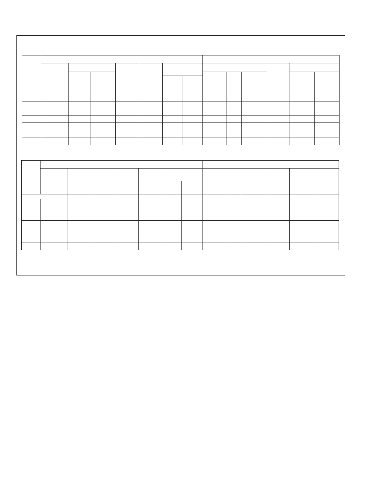
2.4 ELECTRICAL & PHYSICAL DATA (SEE TABLE 1)
TABLE 1
LECTRICAL AND PHYSICAL DATA – 13 SEER
E
LECTRICAL DATA PHYSICAL DATA
E
use or HACR
an Motor
odel
M
Number
Rev.7/29/2009
18 1-60-208-230 9/9 48 0.6 12/12 15/15 20/20 11.06 [1.03] 1 1700 [802] 91 [2580] 144 [65.3] 152 [68.9]
4 1-60-208-230 12.8/12.8 58.3 0.6 17/17 20/20 25/25 11.06 [1.03] 1 2370 [1118] 91 [2580] 130 [59] 138 [62.6]
2
0 1-60-208-230 14.1/14.1 73 0.8 19/19 25/25 30/30 13.72 [1.27] 1 2800 [1321] 101 [2863] 198 [89.8] 208 [94.3]
3
6 1-60-208-230 17/17 96.7 1.2 23/23 30/30 35/35 16.39 [1.52] 1 3575 [1687] 109 [3090] 215 [97.5] 227 [103]
3
2 1-60-208-230 21.8/21.8 112 1.2 29/29 35/35 50/50 21.85 [2.03] 1 3575 [1687] 150 [4252] 202 [91.6] 214 [97.1]
4
8 1-60-208-230 21.8/21.8 117 1.2 29/29 35/35 50/50 21.85 [2.03] 1 3575 [1687] 141 [3997] 205 [93] 217 [98.4]
4
60 1-60-208-230 26.3/26.3 134 1.2 35/35 45/45 60/60 21.85 [2.03] 1 3575 [1687] 228 [6464] 209 [94.8] 221 [100.2]
ELECTRICAL AND PHYSICAL DATA – 14.5 SEER
odel
M
Number
Rev. 7/29/2009
18 1-60-208/230 9/9 48 0.08 13/13 15/15 20/20 13.72 [1.27] 1 2590 [1222] 101.6 [2880] 154 [69.9] 164 [74.4]
24 1-60-208/230 12.8/12.8 58.3 0.08 17/17 25/25 25/25 13.72 [1.27] 1 2590 [1222] 100.8 [2858] 155 [70.3] 165 [74.8]
30 1-60-208/230 14.1/14.1 73 1.23 19/19 25/25 30/30 16.39 [1.52] 1 2595 [1225] 117.8 [3340] 118.5 [53.8] 181 [82.1]
36 1-60-208/230 16.7/16.7 79 1.3 23/23 30/30 35/35 21.85 [2.03] 1 3575 [1687] 136.5 [3870] 193 [87.5] 207 [93.9]
42 1-60-208/230 17.9/17.9 112 1.33 24/24 30/30 40/40 21.85 [2.03] 1 3575 [1687] 162.4 [4604] 193 [87.5] 208 [94.3]
48 1-60-208/230 21.8/21.8 117 2.8 31/31 40/40 50/50 21.85 [2.03] 2 3360 [1586] 258.4 [7326] 265 [120.2] 280 [127]
60 1-60-208/230 26.4/26.4 134 2.8 36/36 45/45 60/60 21.85 [2.03] 2 3360 [1586] 284 [8051] 265 [120.2] 280 [127]
NOTES:
➀ 20 Fins per inch [mm]
➁ Factory charged for 15 ft. [4.6 m] of line set
Phase
requency (Hz)
F
Voltage (Volts)
Phase
Frequency (Hz)
oltage (Volts)
V
ated Load
R
Amperes
RLA)
(
Rated Load
Amperes
RLA)
(
ocked Rotor
L
Amperes
LRA)
(
Locked Rotor
Amperes
LRA)
(
F
ull Load
F
Amperes
FLA)
(
LECTRICAL DATA PHYSICAL DATA
E
Fan Motor
ull Load
F
Amperes
FLA)
(
inimum
M
ircuit
C
Ampacity
mperes
A
Minimum
ircuit
C
Ampacity
mperes
A
F
Circuit Breaker
Minimum
mperes
A
Fuse or HACR
Circuit Breaker
inimum
M
Amperes
Maximum
mperes
A
aximum
M
Amperes
ace Area
F
Face Area
Sq. Ft.
Sq. Ft.
m
[
2
m
[
utdoor Coil WeightCompressor
O
No.
ows
R
2
]
utdoor Coil WeightCompressor
O
N
Rows
]
CFM
L/s]
[
o.
FM
C
[L/s]
efrig.
R
er
P
Circuit
z. [g]
O
Refrig.
er
P
Circuit
z. [g]
O
Net
bs. [kg]
L
et
N
Lbs. [kg]
Shipping
bs. [kg]
L
hipping
S
Lbs. [kg]
3.0 LOCATING UNIT
3.1 CORROSIVE ENVIRONMENT
The metal parts of this unit may be subject to rust or deterioration if exposed to a
corrosive environment. This oxidation could shorten the equipment’s useful life.
Corrosive elements include, but are not limited to, salt spray, fog or mist in seacoast
areas, sulphur or chlorine from lawn watering systems, and various chemical contaminants from industries such as paper mills and petroleum refineries.
If the unit is to be installed in an area where contaminants are likely to be a problem, special attention should be given to the equipment location and exposure.
• Avoid having lawn sprinkler heads spray directly on the unit cabinet.
• In coastal areas, locate the unit on the side of the building away from the waterfront.
• Shielding provided by a fence or shrubs may give some protection, but cannot
violate minimum airflow and service access clearances.
• Elevating the unit off its slab or base enough to allow air circulation will help
avoid holding water against the basepan.
Regular maintenance will reduce the build-up of contaminants and help to protect
the unit’s finish.
6
Page 7
!
WARNING
Disconnect all power to unit before starting maintenance. Failure to do so
can cause electrical shock resulting in severe personal injury or death.
• Frequent washing of the cabinet, fan blade and coil with fresh water will remove
most of the salt or other contaminants that build up on the unit.
Regular cleaning and waxing of the cabinet with an automobile polish will pro-
•
vide some protection.
• A liquid cleaner may be used several times a year to remove matter that will not
wash off with water.
Several different types of protective coil coatings are offered in some areas. These
coatings may provide some benefit, but the effectiveness of such coating materials
cannot be verified by the equipment manufacturer.
3.2 HEAT PUMP LOCATION
Consult local and national building codes and ordinances for special installation
requirements. Following location information will provide longer life and simplified
servicing of the outdoor heat pump.
NOTE: These units must be installed outdoors. No ductwork can be attached, or
other modifications made, to the discharge grille. Modifications will affect performance or operation.
3.3 OPERATIONAL ISSUES
• IMPORTANT: Locate the unit in a manner that will not prevent, impair or com-
promise the performance of other equipment horizontally installed in proximity
to the unit. Maintain all required minimum distances to gas and electric meters,
dryer vents, exhaust and inlet openings. In the absence of National Codes, or
manufacturers’ recommendations, local code recommendations and requirements will take presidence.
• Refrigerant piping and wiring should be properly sized and kept as short as
possible to avoid capacity losses and increased operating costs.
• Locate the unit where water run off will not create a problem with the equip-
ment. Position the unit away from the drip edge of the roof whenever possible.
Units are weatherized, but can be affected by the following:
o Water pouring into the unit from the junction of rooflines, without protective
guttering. Large volumes of water entering the heat pump while in operation
can impact fan blade or motor life, and coil damage may occur to a heat
pump if moisture cannot drain from the unit under freezing conditions.
o Freezing moisture, or sleeting conditions, can cause the cabinet to ice-over
prematurely and prevent heat pump operation, requiring backup heat, which
generally results in less economical operation.
• Closely follow clearance recommendations (See Figure 1).
o 24” [609.6 mm] to the service panel access
o 60” [1524 mm] above heat pump fan discharge (unit top) to prevent recircula-
tion
o 6” [152.4 mm] to heat pump coil grille air inlets (per heat pump).
IMPORTANT: Remove attached shipping strap. Failure to remove strap could result
in internal tubing stress. Plastic strap can be cut off from exterior of the unit and left
inside of unit. See page 30.
3.4 FOR UNITS WITH SPACE LIMITATIONS
In the event that a space limitation exists, we will permit the following clearances:
Single Unit Applications: Clearances below 6 inches [152.4 mm] will reduce unit
capacity and efficiency. Do not reduce the 60-inch [1524 mm] discharge, or the 24inch [609.6 mm] service clearances.
Multiple Unit Applications: When multiple heat pump grille sides are aligned, a 6inch [152.4 mm] per unit clearance is recommended, for a total of 12" [304.8 mm]
between two units. Two combined clearances below 12 inches [304.8 mm] will
reduce capacity and efficiency. Do not reduce the 60-inch [1524 mm] discharge, or
24-inch [609.6 mm] service, clearances.
7
Page 8
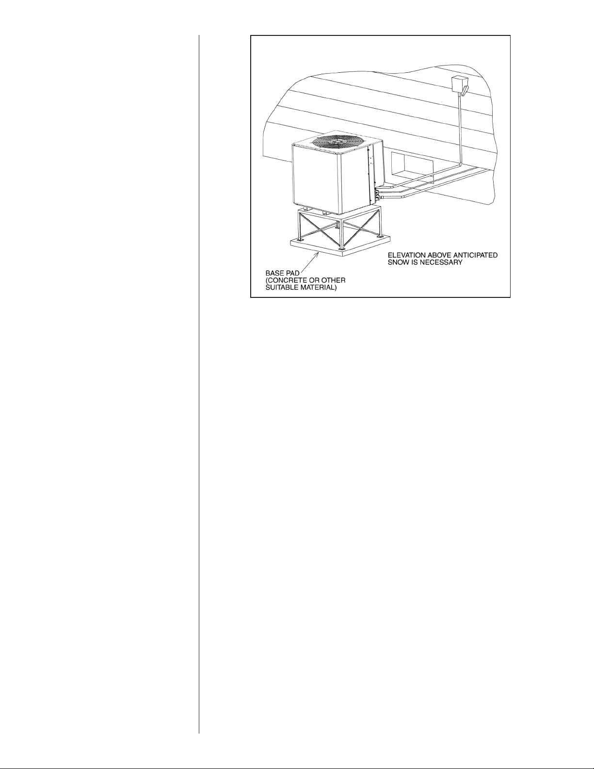
FIGURE 2
ECOMMENDED ELEVATED INSTALLATION
R
• Do not obstruct the bottom drain opening in the heat pump base pan. It is
essential to provide defrost condensate drainage to prevent possible refreezing
of the condensation. Provide a base pad for mounting the unit, which is slightly
pitched away from the structure. Route condensate off the base pad to an area
which will not become slippery and result in personal injury.
• Where snowfall is anticipated, the heat pump must be elevated above the base
pad to prevent ice buildup that may crush the tubing of the heat pump coil or
cause fin damage. Heat pump units should be mounted above the average
expected accumulated snowfall for the area.
3.5 CUSTOMER SATISFACTION ISSUES
• The heat pump should be located away from the living, sleeping and recreational spaces of the owner and those spaces on adjoining property.
• To prevent noise transmission, the mounting pad for the outdoor unit should
not be connected to the structure, and should be located sufficient distance
above grade to prevent ground water from entering the unit.
3.6 UNIT MOUNTING
If elevating the heat pump, either on a flat roof or on a slab, observe the
following guidelines.
• The base pan provided elevates the heat pump 2” [50.8 mm] above the base
pad.
• If elevating a unit on a flat roof, use 4” x 4” [101.6 mm x 101.6 mm] (or equivalent) stringers positioned to distribute unit weight evenly and prevent noise and
vibration (see Figure 2).
NOTE: Do not block drain openings shown in Figure 1.
• If unit must be elevated because of anticipated snow fall, secure unit and elevating stand such that unit and/or stand will not tip over or fall off. Keep in mind
that someone may try to climb on unit.
3.7 FACTORY-PREFERRED TIE-DOWN METHOD FOR OUTDOOR UNITS
IMPORTANT: The Manufacturers approved/recommended method is a guide to securing equipment for wind and seismic loads. Other methods might provide the same result,
but the Manufacturer’s method is the only one endorsed by the Manufacturer for securing equipment where wind or earthquake damage can occur. Additional information is
available in the PTS (Product Technical Support) section of the Manufacturer’s website
Rheemote.net and can be found as a listing under each outdoor model. If you do not
have access to this site, your Distributor can offer assistance.
8
Page 9

4.0 REFRIGERANT CONNECTIONS
All units are factory charged with Refrigerant 410A for 15 ft. [4.6 m] of line set. All
models are supplied with service valves. Keep tube ends sealed until connection is
to be made to prevent system contamination.
5.0 REPLACEMENT UNITS
To prevent failure of a new heat pump unit, the existing tubing system must be correctly sized and cleaned or replaced. Care must be exercised that the expansion
device is not plugged. For new and replacement units, a liquid line filter drier should
be installed and refrigerant tubing should be properly sized. Test the oil for acid. If
positive, a liquid line filter drier is mandatory.
6.0 INDOOR COIL
REFER TO INDOOR COIL MANUFACTURER’S INSTALLATION INSTRUCTIONS.
IMPORTANT: The manufacturer is not responsible for the performance and opera-
tion of a mismatched system, or for a match listed with another manufacturer’s coil.
6.1 LOCATION
Do not install the indoor coil in the return duct system of a gas or oil furnace.
Provide a service inlet to the coil for inspection and cleaning. Keep the coil pitched
toward the drain connection.
CAUTION
When coil is installed over a finished ceiling and/or living area, it is
recommended that a seconda ry sheet metal conden sa te p an be
constructed and installed under entire unit. Failure to do so can result
in property damage.
7.0 INTERCONNECTING TUBING
7.1 VAPOR AND LIQUID LINES
Keep all lines sealed until connection is made.
Make connections at the indoor coil first.
Refer to Line Size Information in Tables 2 and 3 for correct size and multipliers to be
used to determine capacity for various vapor line diameters and lengths of run. The
losses due to the lines being exposed to outdoor conditions are not included.
The factory refrigeration charge in the outdoor unit is sufficient for 15 feet [4.6 m] of
interconnecting lines. The factory refrigeration charge in the outdoor unit is sufficient
for the unit and 15 feet [4.6 m] of standard size interconnecting liquid and vapor
lines. For different lengths, adjust the charge as indicated below.
1/4” ± .3 oz. per foot [6.35 mm ± 8.5 g]
5/16” ± .4 oz. per foot [7.9 mm ± 11.3 g]
3/8” ± .6 oz. per foot [9.5 mm ± 17 g]
1/2” ± 1.2 oz. per foot [12.7 mm ± 34 g]
9
Page 10

7.2 MAXIMUM LENGTH OF LINES
The maximum length of interconnecting line is 150 feet [45.7 m]. Always use the
shortest length possible with a minimum number of bends. Additional compressor
oil is not required for any length up to 150 feet [45.7 m].
NOTE: Excessively long refrigerant lines cause loss of equipment capacity.
7.3 VERTICAL SEPARATION
eep the vertical separation to a minimum. Use the following guidelines when
K
installing the unit:
1. DO NOT exceed the vertical separations as indicated on Table 3.
2. It is recommended to use the smallest liquid line size permitted to minimize system charge which will maximize compressor reliability.
3. Table 3 may be used for sizing horizontal runs.
7.4 TUBING INSTALLATION
Observe the following when installing correctly sized type “L” refrigerant tubing
between the condensing unit and evaporator coil:
• If a portion of the liquid line passes through a hot area where liquid refrigerant
can be heated to form vapor, insulating the liquid line is required.
• Use clean, dehydrated, sealed refrigeration grade tubing.
• Always keep tubing sealed until tubing is in place and connections are to be
made.
• Blow out the liquid and vapor lines with dry nitrogen before connecting to the
outdoor unit and indoor coil. Any debris in the line set will end up plugging the
expansion device.
• As an added precaution it is recommended that a high quality, bi-directional filter drier is installed in the liquid line.
• Do not allow the vapor line and liquid line to be in contact with each other. This
causes an undesirable heat transfer resulting in capacity loss and increased
power consumption. The vapor line must be insulated.
• If tubing has been cut, make sure ends are deburred while holding in a position
to prevent chips from falling into tubing. Burrs such as those caused by tubing
cutters can affect performance dramatically, particularly on small liquid line
sizes.
• For best operation, keep tubing run as short as possible with a minimum number of elbows or bends.
• Locations where the tubing will be exposed to mechanical damage should be
avoided. If it is necessary to use such locations, the copper tubing should be
housed to prevent damage.
• If tubing is to be run underground, it must be run in a sealed watertight chase.
• Use care in routing tubing and do not kink or twist. Use a tubing bender on the
vapor line to prevent kinking.
• Route the tubing using temporary hangers, then straighten the tubing and
install permanent hangers. Line must be adequately supported.
• The vapor line must be insulated to prevent dripping (sweating) and prevent
performance losses. Armaflex and Rubatex are satisfactory insulations for this
purpose. Use 1/2” [12.7 mm] minimum insulation thickness, additional insulation may be required for long runs.
• Check Table 2 for the correct vapor line size. Check Table 3 for the correct liquid line size.
10
Page 11

7.5 TUBING CONNECTIONS
Indoor coils have only a holding charge of dry nitrogen. Keep all tube ends sealed
until connections are to be made.
• Use type “L” copper refrigeration tubing. Braze the connections with accepted
industry practices.
• Be certain both refrigerant shutoff valves at the outdoor unit are closed.
• Clean the inside of the fittings before brazing.
• Remove the cap and schrader core from service port to protect seals from heat
damage.
• Use an appropriate heatsink material around the copper stub and the service
valves before applying heat.
• IMPORTANT: Do not braze any fitting with the TEV sensing bulb attached.
• Braze the tubing between the outdoor unit and indoor coil. Flow dry nitrogen
into a service port and through the tubing while brazing.
• The service valves are not backseating valves. To open the valves, remove the
valve cap with an adjustable wrench. Insert a 3/16” [4.7 mm] or 5/16” [7.9 mm] hex
wrench into the stem. Back out counterclockwise.
• Replace the valve cap finger tight then tighten an additional 1/2 hex flat for a
metal-to-metal seal.
7.6 LEAK TESTING
• Pressurize line set and coil through service fittings with dry nitrogen to 150
PSIG [1034.2 kPa] maximum. Leak test all joints using liquid detergent. If a
leak is found, relieve pressure and repair.
11
Page 12
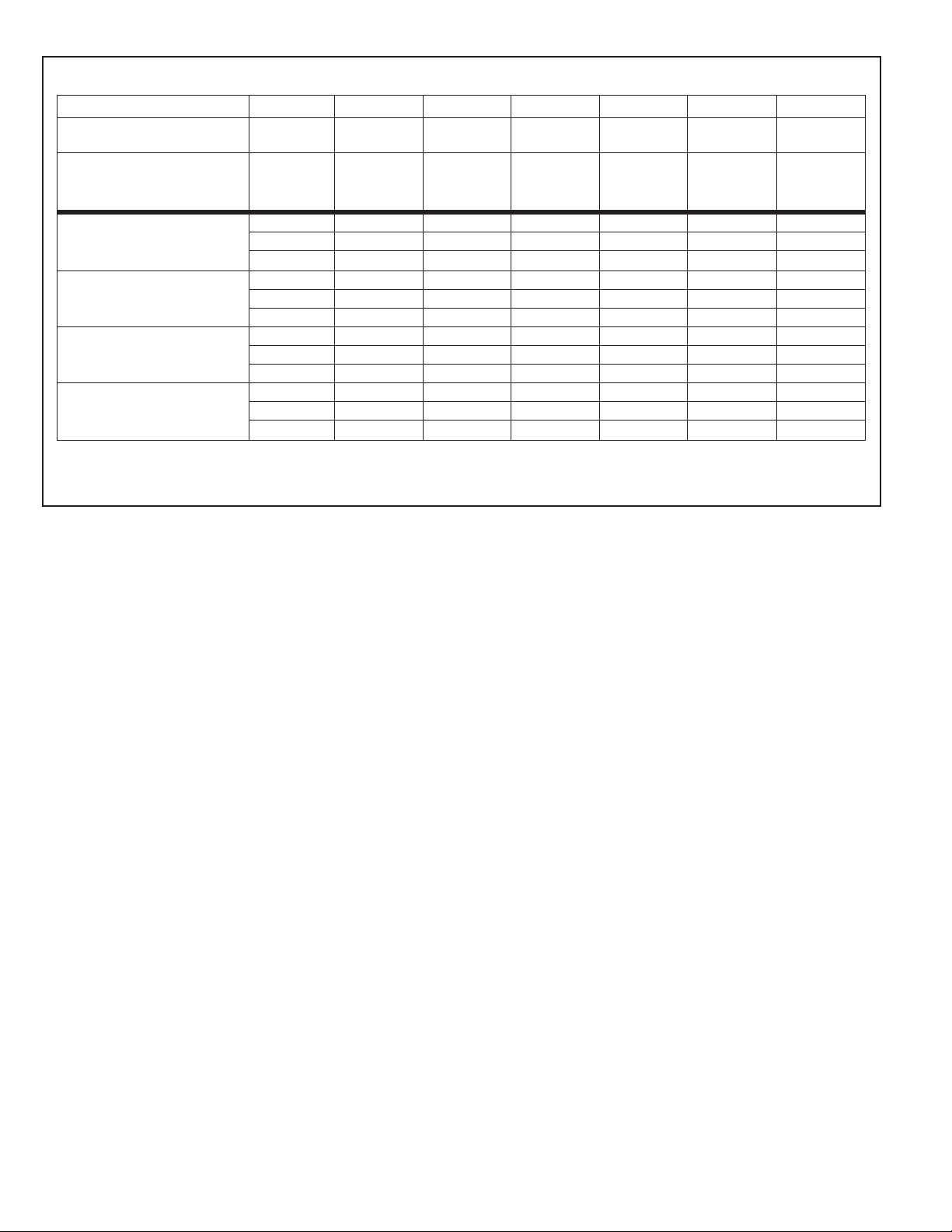
TABLE 2
SUCTION LINE LENGTH/SIZE VS CAPACITY MULTIPLIER (R-410A)
Unit Size
Suction Line Connection Size
Suction Line Run - Feet [m]
ptional
O
25’ [7.6] Standard
— Optional
Optional
50’ [15.24] Standard
— Optional
Optional
100’ [30.5] Standard
— Optional
Optional
150’ [45.7] Standard
— Optional
NOTES:
*Standard line size
Using suction line larger than shown in chart will result in poor oil return and is not recommended.
1 1/2 Ton 2 Ton 2 1/2 Ton 3 Ton 3 1/2 Ton 4 Ton 5 Ton
3/4”
[19] I.D.
5/8 [15.9] Opt.
3/4* [19] Std.
—
3/4”
[19] I.D.
5/8 [15.9] Opt.
3/4* [19] Std.
—
3/4”
[19] I.D.
5/8 [15.9] Opt.
3/4* [19] Std.
7/8 [22.2] Opt.
[19] I.D.
5/8 [15.9] Opt.
3/4* [19] Std.
7/8 [22.2] Opt.
1.00 1.00 1.00 1.00 1.00 1.00 1.00
1.00 1.00 1.00 1.00 1.00 1.00 1.00
——1.00 —— ——
0.98 0.98 0.96 0.98 0.99 0.99 0.99
0.99 0.99 0.98 0.99 0.99 0.99 0.99
——0.99 —— ——
0.95 0.95 0.94 0.96 0.96 0.96 0.97
0.96 0.96 0.96 0.97 0.98 0.98 0.98
——0.97 —— ——
0.92 0.92 0.91 0.94 0.94 0.95 0.94
0.93 0.94 0.93 0.95 0.96 0.96 0.97
——0.95 —— ——
3/4”
7/8”
[22.2] I.D.
3/4 [19] Opt.
7/8* [22.2] Opt.
—
7/8”
[22.2] I.D.
7/8 [22.2] Opt.
1 1/8* [28.6] Std.
—
7/8”
[22.2] I.D.
7/8 [22.2] Opt.
1 1/8* [28.6] Std.
—
12
Page 13

TABLE 3
25 [7.62] 50 [15.24] 75 [22.86] 100 [30.48] 125 [45.72] 150 [45.72]
1/4" [6.35] 25 [7.62] 50 [15.24] 75 [22.86] 77 [23.47] 62 [18.90] 46 [14.02]
5
/16" [7.93] 25 [7.62] 50 [15.24] 75 [22.86] 100 [30.48] 119 [36.27] 115 [35.05]
3/8" [9.52]* 25 [7.62] 50 [15.24] 75 [22.86] 100 [30.48] 125 [38.10] 131 [39.93]
1/4" [6.35] 25 [7.62] 50 [15.24] 35 [10.67] 9 [2.74] N/A N/A
5/16" [7.93] 25 [7.62] 50 [15.24] 75 [22.86] 87 [26.52] 80 [24.38] 74 [22.56]
3/8" [9.52]* 25 [7.62] 50 [15.24] 75 [22.86] 100 [30.48] 102 [31.09] 100 [30.48]
1/4" [6.35] 20 [6.10] N/A N/A N/A N/A N/A
5/16" [7.93] 25 [7.62] 39 [11.89] 29 [8.84] 20 [6.10] 10 [3.05] N/A
3/8" [9.52]* 25 [7.62] 50 [15.24] 48 [14.63] 45 [13.72] 41 [12.50] 38 [11.58]
5/16" [7.93] 25 [7.62] 28 [8.53] 14 [4.27] N/A N/A N/A
3/8" [9.52]* 25 [7.62] 45 [13.72] 41 [12.50] 36 [10.97] 31 [9.45] 27 [8.23]
1/2" [12.70] 25 [7.62] 50 [15.24] 52 [15.85] 51 [15.55] 50 [15.24] 49 [14.94]
5/16" [7.93] 25 [7.62] 50 [15.24] 40 [12.19] 22 [6.71] N/A N/A
3/8" [9.52]* 25 [7.62] 50 [15.24] 65 [19.81] 61 [18.59] 57 [17.37] 54 [16.46]
1/2" [12.70] 25 [7.62] 50 [15.24] 73 [22.25] 73 [22.25] 72 [21.95] 71 [21.64]
5/16" [7.93] N/A N/A N/A N/A N/A N/A
3/8" [9.52]* 15 [4.57] 10 [3.05] N/A N/A N/A N/A
1/2" [12.70] 19 [5.79] 18 [5.49] 17 [5.18] 16 [4.88] 15 [4.57] 14 [4.27]
3/8" [9.52]* 25 [7.62] 24 [7.32] 17 [5.18] 11 [3.35] N/A N/A
1/2" [12.70] 25 [7.62] 35 [10.67] 34 [10.36] 32 [9.75] 31 [9.45] 30 [9.14]
1/4" [6.35] 25 [7.62] 19 [5.79] N/A N/A N/A N/A
5/16" [7.93] 25 [7.62] 43 [13.11] 39 [11.89] 35 [10.67] 31 [9.45] 26 [7.93]
3/8" [9.52]* 25 [7.62] 48 [14.63] 47 [14.33] 46 [14.02] 44 [13.41] 43 [13.11]
1/4" [6.35] 25 [7.62] N/A N/A N/A N/A N/A
5/16" [7.93] 25 [7.62] 43 [13.11] 36 [10.97] 30 [9.14] 23 [7.01] 16 [4.88]
3/8" [9.52]* 25 [7.62] 50 [15.24] 49 [14.94] 47 [14.33] 45 [13.72] 42 [12.80]
1/4" [6.35] 18 [5.49] N/A N/A N/A N/A N/A
5/16" [7.93] 25 [7.62] 37 [11.28] 27 [8.23] 18 [5.49] N/A N/A
3/8" [9.52]* 25 [7.62] 49 [14.94] 46 [14.02] 43 [13.11] 39 [11.89] 36 [10.97]
5/16" [7.93] 25 [7.62] 33 [10.06] 19 [5.79] N/A N/A N/A
3/8" [9.52]* 25 [7.62] 50 [15.24] 46 [14.02] 41 [12.50] 36 [10.97] 32 [9.75]
1/2" [12.70] 25 [7.62] 50 [15.24] 57 [17.37] 56 [17.07] 55 [16.76] 54 [16.46]
5/16" [7.93] 25 [7.62] 50 [15.24] 33 [10.06] 16 [4.88] N/A N/A
3/8" [9.52]* 25 [7.62] 50 [15.24] 66 [20.12] 60 [18.29] 55 [16.76] 49 [14.94]
1/2" [12.70] 25 [7.62] 50 [15.24] 75 [22.86] 74 [22.56] 74 [22.56] 73 [22.25]
5/16" [7.93] 20 [6.10] N/A N/A N/A N/A N/A
3/8" [9.52]* 25 [7.62] 27 [8.23] 19 [5.79] 12 [3.66] N/A N/A
1/2" [12.70] 25 [7.62] 40 [12.19] 38 [11.58] 37 [11.28] 35 [10.67] 33 [10.06]
3/8" [9.52]* 25 [7.62] 37 [11.28] 25 [7.62] 13 [3.96] N/A N/A
1/2" [12.70] 25 [7.62] 50 [15.24] 54 [16.46] 51 [15.55] 49 [14.94] 46 [14.02]
Line Size
(Inch O.D.)
[mm]
Liquid Line Size
Outdoor unit Above or Below Indoor Coil
(Heat Pump Only)
To ta l Equivalent Length - Feet [m]
Maximum Vertical Separation - Feet [m]
3/8" [9.53]
2 1/2 Ton
3/8" [9.53]
R-410A
System
C
apacity
Model
Line Size
Connection
S
ize (Inch
I.D.) [mm]
!"#$%%&
1 1/2 Ton
3/8" [9.53]
2 Ton
3/8" [9.53]
5 Ton
3/8" [9.53]
3 Ton
3/8" [9.53]
3 1/2 Ton
3/8" [9.53]
4 Ton
3/8" [9.53]
1
1/2 Ton
3
/8" [9.53]
2 Ton
4 Ton
3/8" [9.53]
5 Ton
3/8" [9.53]
!'()#$%%&
2 1/2 Ton
3/8" [9.53]
3 Ton
3/8" [9.53]
3 1/2 Ton
3/8" [9.53]
LIQUID LINE SIZING (R-410A)
NOTES:
*Standard line size
N/A - Application not recommended.
13
Page 14

TABLE 4
25 [7.62] 50 [15.24] 75 [22.86] 100 [30.48] 125 [45.72] 150 [45.72]
5/8" [15.88]
3
/4" [19.05]*
7/8" [22.23]
5/8" [15.88]
3/4" [19.05]*
7/8" [22.23]
5/8" [15.88]
3/4" [19.05]*
7/8" [22.23]
5/8" [15.88]
3/4" [19.05]
7/8" [22.23]*
5/8" [15.88]
3/4" [19.05]
7/8" [22.23]*
5/8" [15.88]
3/4" [19.05]
7/8" [22.23]
3/4" [19.05]
7/8" [22.23]
1-1/8" [28.58]*
5/8" [15.88]
3/4" [19.05]*
7/8" [22.23]
5/8" [15.88]
3/4" [19.05]*
7/8" [22.23]
5/8" [15.88]
3/4" [19.05]*
7/8" [22.23]
5/8" [15.88]
3/4" [19.05]*
7/8" [22.23]
5/8" [15.88]
3/4" [19.05]
7/8" [22.23]*
5/8" [15.88]
3/4" [19.05]
7/8" [22.23]*
3/4" [19.05]
7/8" [22.23]*
1-1/8" [28.58]
SUCTION LINE SIZE - OUTDOOR UNIT ABOVE INDOOR COIL
R-410A
S
ystem
Capacity
Model
Line Size
C
onnection
Size (Inch
I.D.) [mm]
Line Size
(Inch O.D.)
[mm]
Suction Line Size
Outdoor Unit ABOVE Indoor Coil (Heat Pumps)
To ta l Equivalent Length - Feet [m]
2 Ton
Same as Liquid Line Size Table
NA
NA
1
1/2 Ton
Same as Liquid Line Size Table
N
A
NA
2 1/2 Ton
Same as Liquid Line Size Table
NA
Same as Liquid Line Size Table
Same as Liquid Line Size Table
3 Ton
Same as Liquid Line Size Table
Same as Liquid Line Size Table
Same as Liquid Line Size Table
3 1/2 Ton
7/8" [22.23]
Same as Liquid Line Size Table
Same as Liquid Line Size Table
Same as Liquid Line Size Table
!"#$%%&
1 1/2 Ton
Same as Liquid Line Size Table
NA
NA
!'()#$%%&
4 Ton
7/8" [22.23]
Same as Liquid Line Size Table
Same as Liquid Line Size Table
Same as Liquid Line Size Table
5 Ton
7/8" [22.23]
Same as Liquid Line Size Table
Same as Liquid Line Size Table
2 Ton
Same as Liquid Line Size Table
NA
NA
2 1/2 Ton
Same as Liquid Line Size Table
Same as Liquid Line Size Table
NA
3 Ton
Same as Liquid Line Size Table
Same as Liquid Line Size Table
Same as Liquid Line Size Table
3 1/2 Ton
7/8" [22.23]
Same as Liquid Line Size Table
Same as Liquid Line Size Table
Same as Liquid Line Size Table
4 Ton
7/8" [22.23]
Same as Liquid Line Size Table
Same as Liquid Line Size Table
Same as Liquid Line Size Table
5 Ton
7/8" [22.23]
Same as Liquid Line Size Table
Same as Liquid Line Size Table
NA
3
/4" [19.05]
3/4" [19.05]
3/4" [19.05]
3/4" [19.05]
3/4" [19.05]
3/4" [19.05]
3/4" [19.05]
3/4" [19.05]
UCTION LINE SIZING (R-410A)
S
NOTES:
*Standard line size
N/A - Application not recommended.
14
Page 15

TABLE 5
25 [7.62] 50 [15.24] 75 [22.86] 100 [30.48] 125 [45.72] 150 [45.72]
5/8" [15.88]
3
/4" [19.05]*
7/8" [22.23]
5/8" [15.88]
3/4" [19.05]*
7/8" [22.23]
5/8" [15.88]
3/4" [19.05]*
7/8" [22.23]
5/8" [15.88]
3/4" [19.05]
7/8" [22.23]*
5/8" [15.88]
3/4" [19.05]
7/8" [22.23]*
5/8" [15.88]
3/4" [19.05]
7/8" [22.23]
3/4" [19.05]
7/8" [22.23]
1-1/8" [28.58]*
5/8" [15.88]
3/4" [19.05]*
7/8" [22.23]
5/8" [15.88]
3/4" [19.05]*
7/8" [22.23]
5/8" [15.88]
3/4" [19.05]*
7/8" [22.23]
5/8" [15.88]
3/4" [19.05]*
7/8" [22.23]
5/8" [15.88]
3/4" [19.05]
7/8" [22.23]*
5/8" [15.88]
3/4" [19.05]
7/8" [22.23]*
3/4" [19.05]
7/8" [22.23]*
1-1/8" [28.58]
SUCTION LINE SIZE - OUTDOOR UNIT BELOW INDOOR COIL
R-410A
S
ystem
Capacity
Model
Line Size
C
onnection
Size (Inch
I.D.) [mm]
Line Size
(Inch O.D.)
[mm]
Suction Line Size
Outdoor Unit BELOW Indoor Coil (Heat Pumps)
To ta l Equivalent Length - Feet [m]
1
1/2 Ton
Same as Liquid Line Size Table
N
A
NA
NA
2 1/2 Ton
Same as Liquid Line Size Table
Same as Liquid Line Size Table
Same as Liquid Line Size Table
NA
2 Ton
Same as Liquid Line Size Table
Same as Liquid Line Size Table
NA
Same as Liquid Line Size Table
3 Ton
Same as Liquid Line Size Table
Same as Liquid Line Size Table
Same as Liquid Line Size Table
3 1/2 Ton
7/8" [22.23]
Same as Liquid Line Size Table
Same as Liquid Line Size Table
Same as Liquid Line Size Table
!"#$%%&
1 1/2 Ton
Same as Liquid Line Size Table
NA
NA
!'()#$%%&
4 Ton
7/8" [22.23]
Same as Liquid Line Size Table
Same as Liquid Line Size Table
Same as Liquid Line Size Table
5 Ton
7/8" [22.23]
Same as Liquid Line Size Table
Same as Liquid Line Size Table
2 Ton
Same as Liquid Line Size Table
Same as Liquid Line Size TableNANA
2 1/2 Ton
Same as Liquid Line Size Table
Same as Liquid Line Size Table
Same as Liquid Line Size Table
NA
3 Ton
Same as Liquid Line Size Table
Same as Liquid Line Size Table
Same as Liquid Line Size Table
3 1/2 Ton
7/8" [22.23]
Same as Liquid Line Size Table
Same as Liquid Line Size Table
Same as Liquid Line Size Table
4 Ton
7/8" [22.23]
Same as Liquid Line Size Table
Same as Liquid Line Size Table
Same as Liquid Line Size Table
5 Ton
7/8" [22.23]
Same as Liquid Line Size Table
Same as Liquid Line Size Table
Same as Liquid Line Size Table
NA
3
/4" [19.05]
3/4" [19.05]
3/4" [19.05]
3/4" [19.05]
3/4" [19.05]
3/4" [19.05]
3/4" [19.05]
3/4" [19.05]
UCTION LINE SIZING (R-410A)
S
NOTES:
*Standard line size
N/A - Application not recommended.
15
Page 16

8.0 DEMAND DEFROST CONTROL AND
8.0 HIGH/LOW PRESSURE CONTROLS
The demand defrost control is a printed circuit board assembly consisting of solid
state control devices with electro-mechanical outputs. The demand defrost control
monitors the outdoor ambient temperature, outdoor coil temperature, and the compressor run-time to determine when a defrost cycle is required.
Enhanced Feature Demand Defrost Control: Has high and low pressure control
inputs with unique pressure switch logic built into the microprocessor to provide
compressor and system protection without nuisance lock-outs. Cycles the compressor off for 5 seconds at the beginning and end of the defrost cycle to eliminate the
increased compressor noise caused by rapidly changing system pressures when
the reversing valve switches. See section 8.7 for diagnostic flash codes for the two
diagnostic LED’s provided on the control.
8.1 DEFROST INITIATION
A defrost will be initiated when the three conditions below are satisfied:
1) The outdoor coil temperature is below 35°F.
2) The compressor has operated for at least 34 minutes with the outdoor coil temperature below 35°F.
3) The measured difference between the ambient temperature and the outdoor
coil temperature exceeds a certain threshold.
Additionally, a defrost will be initiated if six hours of accumulated compressor run-time
has elapsed without a defrost with the outdoor coil temperature below 35°F.
8.2 DEFROST TERMINATION
Once a defrost is initiated, the defrost will continue until fourteen minutes has
elapsed or the coil temperature has reached the terminate temperature. The terminate temperature is factory set at 70°F, although the temperature can be changed
to 50°F, 60°F, 70°F or 80°F by relocating a jumper on the board.
8.3 TEMPERATURE SENSORS
The coil sensor is clipped to the top tube on the outdoor coil at the point feed by the
distribution tubes from the expansion device (short 3/8” dia. tube). The air sensor is
located on the defrost control board.
If the ambient sensor fails the defrost control will initiate a defrost every 34 minutes
with the coil temperature below 35°F.
If the coil sensor fails the defrost control will not initiate a defrost.
8.4 TEST MODE
The test mode is initiated by shorting the TEST pins. In this mode of operation, the
enable temperature is ignored and all timers are sped up by a factor of 240. To initiate a manual defrost, short the TEST pins. Remove the short when the system
switches to defrost mode. The defrost will terminate on time (14 minutes) or when
the termination temperature has been achieved. Short TEST pins again to terminate the defrost immediately.
8.5 TROUBLE SHOOTING DEMAND DEFROST OPERATION
Set the indoor thermostat select switch to heat and thermostat lever to a call for
heat.
Jumper the “test pins” to put the unit into defrost. If the unit goes into defrost and
comes back out of defrost, the indication is that the control is working properly.
If the unit did not go into defrost using the test pins, check to ensure that 24V is
being supplied to the control board. If 24V is present then replace the control.
16
Page 17

8.6 HIGH/LOW PRESSURE CONTROL MONITORING
Status of high and low pressure controls is monitored by the enhanced feature
demand defrost control and the following actions are taken.
High Pressure Control (optional) – Provides active protection in both cooling and
heating modes at all outdoor ambient temperatures. The high pressure control is an
automatic reset type and opens at approximately 610 psig and closes at approximately 420 psig. The compressor and fan motor will stop when the high pressure
control opens and will start again if the high side pressure drops to approximately
420 psig when the automatic reset high pressure control resets. If the high pressure
control opens 3 times within a particular call for heating or cooling operation, the
defrost control will lock out compressor and outdoor fan operation.
Low Pressure Control (standard) – Provides active protection in both heating and
cooling modes at all outdoor ambient temperatures. The low pressure control is an
automatic reset type and opens at approximately 15 psig and closes at approximately 40 psig. Operation is slightly different between cooling and heating modes.
Cooling Mode: The compressor and fan motor will stop when the low pressure
control opens and will start again when the low side pressure rises to approximately 40 psig when the low pressure control automatically resets. If the low
pressure switch opens 3 times within a particular call for cooling operation, the
defrost control will lock out compressor and outdoor fan operation.
Heating Mode: The compressor and fan motor will stop when the low pressure
control opens and will start again when the low side pressure rises to approximately 40 psig when the low pressure control automatically resets. If the low
pressure switch trips 3 times within 120 minutes of operation during a particular
call for heating operation, the defrost control will lock out compressor and outdoor fan operation. If the lock-out due to low pressure occurs at an outdoor
ambient temperature below 5°F, the defrost control will automatically exit the
lock-out mode when the outdoor ambient temperature rises to 5°F. This feature
is necessary since the low pressure control could possibly heave opened due to
the outdoor ambient being very low rather than an actual system fault.
Exiting Lock-Out Mode: To exit the lock-out mode, remove 24 volts to the defrost
control by removing power to indoor air-handler/furnace or by shorting the two
defrost control test pins together.
8.7 ENHANCED FEATURE DEFROST CONTROL DIAGNOSTIC CODES
LED 1 LED 2 Control Board Status
OFF OFF No Power
ON ON Coil Sensor Failure
OFF ON Ambient Sensor Failure
FLASH FLASH Normal
OFF FLASH Low Pressure Lockout (short test pins to reset)
FLASH OFF High Pressure Lockout (short test pins to reset)
ON FLASH Low Pressure Control Open
FLASH ON High Pressure Control Open
Alternate Flashing 5 Minute Time Delay
9.0 START-UP – CHECKING AIRFLOW
The air distribution system has the greatest effect on airflow. The duct system is
totally controlled by the contractor. For this reason, the contractor should use only
industry-recognized procedures. The correct air quantity is critical to air conditioning
systems. Proper operation, efficiency, compressor life, and humidity control depend
on the correct balance between indoor load and outdoor unit capacity. Excessive
indoor airflow increases the possibility of high humidity problems. Low indoor airflow
reduces total capacity and causes coil icing. Serious harm can be done to the compressor by low airflow, such as that caused by refrigerant flooding. Heat pump systems require a specified airflow. Each ton of cooling requires between 375 and 450
cubic feet of air per minute (CFM). See the manufacturer’s spec sheet for rated airflow for the system being installed. Duct design and construction should be carefully
done. System performance can be lowered dramatically through bad planning or
workmanship. Air supply diffusers must be selected and located carefully. They
must be sized and positioned to deliver treated air along the perimeter of the space.
If they are too small for their intended airflow, they become noisy. If they are not
located properly, they cause drafts. Return air grilles must be properly sized to carry
air back to the blower. If they are too small, they also cause noise. The installers
should balance the air distribution system to ensure proper quiet airflow to all rooms
in the home. This ensures a comfortable living space.
17
Page 18

Altitude
(feet)
SENSIBLE HEAT
CONSTANT
(SHC)
ALTITUDE
(FEET)
SENSIBLE HEAT
CONSTANT
(SHC)
Sea Level 1.08 6000 0.87
500 1.07 7000 0.84
1000 1.05 8000 0.81
2000 1.01 9000 0.78
3000 0.97 10000 0.75
4000 0.94 15000 0.61
5000 0.90 20000 0.50
These simple mathematical formulas can be used to determine the CFM in a residential or light commercial system. Electric resistance heaters can use:
olts x amps x 3.413
CFM =
Gas furnaces can use:
FM =
C
*Refer to furnace data plate for furnace output capacity. SHC = Sensible Heat
Constant (see table below), an air velocity meter or airflow hood can give a more
accurate reading of the system CFM. The measurement for temperature rise should
be performed at the indoor coil inlet and near the outlet, but out of direct line of sight
of the heater element or heat exchanger. For best results, measure air temperature
at multiple points and average the measurements to obtain coil inlet and outlet temperatures.
v
SHC x temp rise
Output Capacity in BTUH*
SHC x temp rise
10.0 EVACUATION AND LEAK TESTING
10.1 EVACUATION PROCEDURE
Evacuation is the most important part of the entire service procedure. The life and
efficiency of the equipment is dependent upon the thoroughness exercised by the
serviceman when evacuating air and moisture from the system.
Air or nitrogen in the system causes high condensing temperatures and pressure,
resulting in increased power input and non-verifiable performance.
Moisture chemically reacts with the refrigerant and oil to form corrosive hydrofluoric
acid. This attacks motor windings and parts, causing breakdown.
• After the system has been leak-checked and proven sealed, connect the vacuum
pump and evacuate system to 500 microns and hold 500 microns or less for at
least 15 minutes. The vacuum pump must be connected to both the high and low
18
sides of the system by connecting to the two pressure ports. Use the largest size
connections available since restrictive service connections may lead to false
readings because of pressure drop through the fittings.
• After adequate evacuation, open both service valves by removing both brass service valve caps with an adjustable wrench. Insert a 3/16” [5 mm] or 5/16” [8 mm]
hex wrench into the stem and turn counterclockwise until the wrench stops.
• At this time gauges must be connected to the access fitting on the liquid line
(small) service valve and the common suction port connected to the common suction line between the reversing valve and compressor to check and adjust charge.
IMPORTANT: Compressors (especially scroll type) should never be used to evacuate the air conditioning system because internal electrical arcing may result in a
damaged or failed compressor. Never run a scroll compressor while the system is in
a vacuum or compressor failure will occur.
10.2 FINAL LEAK TESTING
After the unit has been properly evacuated and service valves opened, a halogen
leak detector should be used to detect leaks in the system. All piping within the heat
pump, evaporator, and interconnecting tubing should be checked for leaks. If a leak
is detected, the refrigerant should be recovered before repairing the leak. The
Clean Air Act prohibits releasing refrigerant into the atmosphere.
Page 19

11.0 CHECKING REFRIGERANT CHARGE
WARNING
!
he top of the scroll compressor shell is hot. Touching the compressor
T
top may result in serious personal injury.
Charge for all systems should be checked against the Charging Chart inside the
access panel cover.
IMPORTANT:Use factory-approved charging method as outlined on the next 4
pages to ensure proper system charge.
NOTICE
!
The optimum refrigerant charge for any outdoor unit matched with a
CFL/CFM/H*L indoor coil/air handler is affected by the application.
Therefore, charging data has been developed to assist the field technician
in optimizing the charge for all mounting configurations (UF – Upflow, DF
– downflow, LH – Left Hand Discharge, and RH – Right Hand Discharge).
Refer to the charging chart inside the access panel cover on the unit and
choose the appropriate column for the specific application being installed
or serviced. New installations utilizing either a CFL/CFM indoor coil
installed on a gas furnace or an H*L air handler in the downflow or horizontal right hand discharge may require removal of refrigerant since the
factory charge could result in an overcharge condition.
11.1 CHARGING UNITS WITH R-410A REFRIGERANT
CAUTION
!
R-410A pressures are approximately 60% higher (1.6 times) than R-22
pressures. Use appropriate care when using this refrigerant. Failure to
exercise care may result in equipment damage or personal injury.
Charge for all systems should be checked against the Charging Chart inside the
access panel cover.
IMPORTANT:Do not operate the compressor without charge in the system.
Addition of R-410A will raise high-side pressures (liquid, and discharge).
NOTICE
!
System maintenance is to be performed by a qualified and certified technician.
The following method is used for charging systems in the cooling and heating
mode. All steps listed should be performed to insure proper charge has been set.
For measuring pressures, the service valve port on the liquid valve (small valve)
and the service port on the suction line between the reversing valve and compressor are to be used.
CONFIRM ID AIR FLOW & COILS ARE CLEAN
Confirm adequate Indoor supply air flow prior to starting the system. See the
Technical Specification sheet for rated air flow for each ID/OD unit match. Air
filter(s) and coils (indoor & outdoor) are to be clean and free of frost prior to starting
the system. Supply Air flow must be between 375 and 450 cfm per rated cooling ton
prior to adjusting system charge. If a humidification system is installed disengage it
from operating prior to charge adjustment. Refer to the “Checking Airflow” section of
this manual for further instruction.
19
Page 20

NOTICE
t
h
j y
!
Verify system components are matched according to the outdoor unit
Specification Sheet.
11.2 MEASUREMENT DEVICE SETUP
Step 1. With an R410A gauge set, attach the high pressure hose to the access
Step 2. Attach the low pressure hose to the common suction port connected to the
Step 3. Attach a temperature probe within 6” outside of the unit on the copper
fitting on the liquid line (small) service valve at the OD unit.
common suction line between the reversing valve and compressor.
liquid line (small line). For more accurate measurements clean the copper
line prior to measurement and use a calibrated clamp on temperature
probe or an insulated surface thermocouple.
11.3 CHARGING BY WEIGHT
NOTICE
!
ADJUST THE SYSTEM CHARGE BY WEIGHT FOR THE STRAIGHT
LENGTH OF THE REFRIGERANT LINE SET.
For a new installation, evacuation of interconnecting tubing and indoor coil is
adequate; otherwise, evacuate the entire system. Use the factory charge shown in
“Electrical and Physical Data” on page 6 of these instructions or on the unit data
plate. Note that the charge value includes charge required for 15 ft. [4.6 m] of
standard-size inter-connecting liquid line without a filter drier. Calculate actual
charge required with installed liquid line size and length using:
1/4” [6.4 mm] O.D. = .3 oz./ft. [8.5 g/.30 m]
5/16” [7.9 mm] O.D. = .4 oz./ft. [11.3 g/.30 m]
3/8” [9.5 mm] O.D. = .6 oz./ft. [17.0 g/.30 m]
1/2” [12.7 mm] O.D. = 1.2 oz./ft. [34.0 g/.30 m]
Add 6 oz. for field-installed filter drier.
With an accurate scale (+/– 1 oz. [28.3 g]) or volumetric charging device, adjust
charge difference between that shown on the unit data plate and that calculated for
the new system installation. If the entire system has been evacuated, add the total
calculated charge.
IMPORTANT: Charging by weight is not always accurate since the application can
affect the optimum refrigerant charge. Charging by weight is considered a starting
point ONLY. Always check the charge by using the charging chart and adjust as
necessary. CHARGING BY LIQUID SUB-COOLING MUST BE USED FOR FINAL
CHARGE ADJUSTMENT.
FIGURE 3
20
With thermostat in the “Off” position, turn the power on to the furnace or air handler
and the heat pump. Start the heat pump and the furnace or air handler with the
thermostat.
Page 21

11.4 GROSS CHARGING BY PRESSURES
Step 1. Following air flow verification and charge weigh in, run the unit for a
IMPORTANT: Indoor conditions as measured at the indoor coil must be within 2°F
of the following during gross charge (pressure) evaluation:
minimum of 15 minutes prior to noting pressures and temperature.
Cooling Mode: 80°F Dry Bulb
Heating Mode: 70°F Dry Bulb
NOTICE
!
If the Indoor temperature is above or below this range, run the system to
bring the temperature down or run the electric heat/furnace to bring the
temperature within this range. System pressure values provided in the
Charge Chart for outdoor dry bulbs corresponding to conditions outside
of ranges listed below, are provided as reference ONLY.
Step 2. Note the Outdoor Dry Bulb Temperature, ODDB°F = _______°F. Unit
Step 3. Locate and note the design pressures. The correct liquid and vapor
Step 4. If the measured liquid pressure is below the listed requirement for the given
charging is recommended under the following outdoor conditions ONLY:
Cooling Mode ONLY: 55°F outdoor dry bulb and above
Heating Mode ONLY: Between 40°F and 60°F outdoor dry bulb
pressures are found at the intersection of theInstalled system and the
outdoor ambient temperature on the Charging Chart located on the inside
of the control box cover of the outdoor unit.
Liquid Pressure: = ______psig; Vapor Pressure = ______psig
NOTICE
!
The refrigerant pressures provided are for gross charge check ONLY.
These pressure values are typical, but may vary due to application.
Evaporator (indoor coil in cooling mode / outdoor coil in heating mode)
load will cause pressures to deviate. Notice that all systems have unique
pressure curves. The variation in the slope and value is determined by the
component selection for that indoor/outdoor matched system. The
variation from system to system seen in the table is normal. The values
listed are for the applicable indoor coil match ONLY!
outdoor and indoor conditions, add charge. If the measured liquid pressure
is above the listed requirement for the given Outdoor and Indoor conditions
remove charge.
11.5 FINAL CHARGE BY SUB-COOLING
Step 1. After gross charging note the designed Sub-Cool value. The correct sub-
IMPORTANT: Indoor conditions as measured at the indoor coil are required to be
between 70°F and 80°F dry bulb for fine tune unit charge adjustment. Unit charging
is recommended under the following outdoor conditions ONLY:
cooling value is found at the intersection of the Installed system and the
outdoor ambient temperature on the Charging Chart located on the inside
of the control box cover of the outdoor unit.
SC° from Charging Chart = _________°F.
Cooling Mode ONLY: 55°F outdoor dry bulb and above
Heating Mode ONLY: Between 40°F and 60°F outdoor dry bulb
NOTICE
!
If the Indoor temperature is above or below the recommended range, run
the system to bring the temperature down or run the electric heat/furnace
to bring the temperature up. System sub-cooling values provided in the
Charge Chart for outdoor dry bulbs corresponding to conditions outside
of the above range, are provided as reference ONLY.
Step 2. Note the measured Liquid Pressure, Pliq = ______psig, as measured from
the liquid (small) service valve. Use the pressure temperature chart below
to note the corresponding saturation temperature for R410A at the
measured liquid pressure.
Liquid Saturation Temperature, SAT°F= _________°F.
21
Page 22

TABLE 6
S
ATURATION
TEMP
(Deg. F)
R
-410A
PSIG
S
ATURATION
TEMP
(Deg. F)
R
-410A
PSIG
S
ATURATION
TEMP
(Deg. F)
R
-410A
PSIG
S
ATURATION
TEMP
(Deg. F)
R
-410A
PSIG
-150 - -30 17.9 35 107.5 100 317.4
-140 - -25 22 40 118.5 105 340.6
-130 - -20 26.4 45 130.2 110 365.1
-
120 - -15 31.3 50 142.7 115 390.9
-110 - -10 36.5 55 156.0 120 418.0
-100 - -5 42.2 60 170.1 125 446.5
-
90 - 0 48.4 65 185.1 130 476.5
-80 - 5 55.1 70 201.0 135 508.0
-70 - 10 62.4 75 217.8 140 541.2
-60 0.4 15 70.2 80 235.6 145 576.0
-50 5.1 20 78.5 85 254.5 150 612.8
-40 10.9 25 87.5 90 274.3
-35 14.2 30 97.2 95 295.3
Step 3. Note the liquid line temperature, Liq° = __________°F, as measured from
Step 4. Subtract the liquid line temperature (Step 3) from the saturation
22
Step 5. Adjust Charge to obtain the specified sub-cooling value. If the measured
IMPORTANT: Excessive use of elbows in the refrigerant line set can produce
excessive pressure drop. Follow industry best practices for installation. Installation
and commissioning of this equipment is to be preformed by trained and qualified
HVAC professionals. For technical assistance contact your Distributor Service
Coordinator.
11.6 FINISHING UP INSTALLATION
• Disconnect pressure gauges from pressure ports; then replace the pressure port
• Replace the service valve caps finger-tight and then tighten with an open-end
• Replace control box cover and service panel and install screws to secure service
• Restore power to unit at disconnect if required.
• Configure indoor thermostat per the thermostat installation instructions and set
a temperature probe located within 6” outside of the unit on the copper
liquid line (small line). It is recommended to use a calibrated clamp on
temperature probe or an insulated surface thermocouple.
temperature (Step 2) to calculate Sub-Cooling. SAT°F______ - Liq°______
= SC°_______
sub-cool is below the listed requirement for the given outdoor and indoor
conditions, add charge. If the measured sub-cool is above the listed
requirement for the given outdoor and indoor conditions remove charge.
NOTICE
!
Systems should not be fine tune charged below 40°F outdoor dry bulb.
caps and tighten adequately to seal caps. Do not over tighten.
wrench adequately to seal caps. Do not over tighten.
panel.
thermostat to desired mode and temperature.
Page 23

12.0 ELECTRICAL WIRING
NOTE: Check all wiring to be sure connections are securely fastened, electrically
isolated from each other and that the unit is properly grounded.
WARNING
!
Turn off electric power at the fuse box or service panel before making any
electrical connections.
lso, the ground connection must be completed before making line volt-
A
ge connections. Failure to do so can result in electrical shock, severe
a
ersonal injury or death.
p
Field wiring must comply with the National Electric Code (C.E.C. in Canada) and
any applicable local code.
12.1 POWER WIRING
It is important that proper electrical power from a commercial utility is available at
the heat pump contactor. Voltage ranges for operation are shown in Table 7.
Install a branch circuit disconnect within sight of the unit and of adequate size to
handle the starting current (see Table 1).
Power wiring must be run in a rain-tight conduit. Conduit must be run through the
connector panel below the access cover (see Figure 1) and attached to the bottom
of the control box.
Connect power wiring to contactor located in outdoor heat pump electrical box. (See
wiring diagram attached to unit access panel.)
Check all electrical connections, including factory wiring within the unit and make
sure all connections are tight.
DO NOT connect aluminum field wire to the contactor terminals.
12.2 GROUNDING
A grounding lug is provided near the contactor for a ground wire.
!
The unit must be permanently grounded. Failure to do so can cause electrical shock resulting in severe personal injury or death.
TABLE 7
VOLTAGE RANGES (60 HZ)
Nameplate Voltage Maximum Load Design Conditions for
208/230 (1 Phase) 187 - 253
12.3 CONTROL WIRING
(See Figure 5)
If the low voltage control wiring is run in conduit with the power supply, Class I insulation is required. Class II insulation is required if run separate. Low voltage wiring
may be run through the insulated bushing provided in the 7/8” [22.2 mm] hole in the
base panel, up to and attached to the pigtails from the bottom of the control box.
Conduit can be run to the base panel if desired by removing the insulated bushing.
A thermostat and a 24 volt, 40 VA minimum transformer are required for the control
circuit of the condensing unit. The furnace or the air handler transformer may be
used if sufficient. See the wiring diagram for reference.
WARNING
Operating Voltage Range at Copeland
Compressors
23
Page 24

FIGURE 4
B
W2
G
Y
W1
B
ODD
C
R
Air Handler
Y
G
W2
E
H
eat Pump Thermostat
Heat Pump
Outdoor Unit
Y
B
C
R
R
D
C
Y
Field Installed
Line Voltage
-
WIRING INFORMATION
Factory Standard
-
W/BL
G/BK
Y
W/BK
G/Y
BR
BL
R
N
OTE: RED WIRE REQUIRED WITH RANCO DDL DEMAND DEFROST CONTROL.
ONTROL WIRING FOR AIR HANDLER
C
YPICAL THERMOSTAT:
T
EAT PUMP WITH
H
LECTRIC HEAT
E
NOTES:
1. Jumper “E” to “W2” to
transfer control of
supplemental heat to
1st stage when the
emergency heat switch
is on.
2. This wire turns on heat
for defrost, omit for most
economical operation.
3. Wire with colored tracing
stripe.
13.0 FIELD INSTALLED ACCESSORIES
13.1 COMPRESSOR CRANKCASE HEATER (CCH)
While scroll compressors usually do not require crankcase heaters, there are
instances when a heater should be added. Refrigerant migration during the off cycle
can result in a noisy start up. Add a crankcase heater to minimize refrigeration
migration, and to help eliminate any start up noise or bearing “wash out.”
TABLE 8
MAXIMUM SYSTEM CHARGE VALUES 13 & 14.5 SEER
Model Compressor Charge Limit Without
*These compressors come with factory installed crankcase heaters.
NOTE: Model sizes 48 and 60 have a factory installed crankcase heater.
Size Model Number Crankcase Heater
Model Compressor Charge Limit Without
Size Model Number Crankcase Heater
13 SEER Maximum Charge Values
18 ZP16K5E-PFV 9.6 lbs. [66.1 kPa]
18 H82J13BABCA *
24 ZP21K5E-PFV 9.6 lbs. [66.1 kPa]
30 ZP25K5E-PFV 9.6 lbs. [66.1 kPa]
30 H81J22BABCA *
36 ZP31K5E-PFV 9.6 lbs. [66.1 kPa]
36 HRH031U1LP6 9.6 lbs. [66.1 kPa]
42 ZP36K5E-PFV 12 lbs. [82.65 kPa]
42 HRH036U1LP6 9.6 lbs. [66.1 kPa]
48 ZP42K5E-PFV 12 lbs. [82.65 kPa]
60 ZP54K5E-PFV *
14.5 SEER Maximum Charge Values
18 ZP16K5E 9.6 lbs. [66.2 kPa]
24 ZP21K5E 9.6 lbs. [66.2 kPa]
30 ZP25K5E 9.6 lbs. [66.2 kPa]
36 ZP31K5E 9.6 lbs. [66.2 kPa]
42 ZP34K5E 12 lbs. [82.7 kPa]
24
Page 25

NOTE: The installation of a crankcase heater is recommended if the system charge
exceeds the values in Table 7.
All heaters are located on the lower half of the compressor shell. Its purpose is to
drive refrigerant from the compressor shell during long off cycles, thus preventing
damage to the compressor during start-up.
At initial start-up or after extended shutdown periods, make sure the heater is energized for at least 12 hours before the compressor is started. (Disconnect switch on
and wall thermostat off.)
13.2 LOW AMBIENT CONTROL (LAC) – COOLING MODE ONLY - RXAD-A08
This component senses compressor head pressure and shuts the heat pump fan off
when the head pressure drops to approximately 220 PSIG [1516.8 kPa]. This
allows the unit to build a sufficient head pressure at lower ambient in order to maintain system balance and obtain improved capacity. Low ambient control should be
used on all equipment operated below 70°F [21.1°C] ambient.
13.3 HIGH PRESSURE CONTROL (HPC)
This control keeps the compressor from operating in pressure ranges which can
cause damage to the compressor. This control is in the low voltage control circuit.
High pressure control (HPC) is a manual reset which opens near 610 PSIG [4205.8
kPa]. Do not reset arbitrarily without first determining what caused it to trip.
13.4 HEAT PUMP THERMOSTAT WARNING LIGHT KIT RXPX-D01
This component senses a compressor lock out and tells the thermostat service light
to come on. This will let the homeowner know that service is needed on the system.
NOTE: Warning light on thermostat will come on during a 5 minute compressor time
delay and for 5 seconds during defrost while the compressor is off. Homeowner
should only be concerned if light stays on for more than 5 minutes.
14.0 SERVICE
14.1 SINGLE-POLE COMPRESSOR CONTACTOR (CC)
CAUTION
Single-pole contactors are used on all standard single-phase units up
through 5 tons. Caution must be exercised when servicing as only one leg
of the power supply is broken with the contactor.
25
Page 26

15.0 TROUBLE SHOOTING
In diagnosing common faults in the heat pump system, develop a logical thought
pattern as used by experienced technicians. The charts which follow are not intended to be an answer to all problems but only to guide the technician’s thinking.
Through a series of yes and no answers, follow the logical path to a likely conclusion.
A novice technician should use these charts like a road map. Remember that the
hart should clarify a logical path to the problem’s solution.
c
15.1 ELECTRICAL CHECKS FLOW CHART
Repair and Recheck
YES NO for Cooling or Heating
Unit Running?
NO YES
Thermostat Problem? Go to
Mechanical Checks
Transformer Problem?
Repair and Recheck
Compressor Internal or Fuses Open
Compressor Winding Open Hot Gas Sensor
YES NO
Voltage on Compressor
Side of Contactor?
YES NO
Run Capacitor Voltage on Line
Side of Contactor?
Start Capacitor
NO YES
Potential Relay
Circuit Breakers Compressor Contactor
Overload Open Hi Pressure Cut-Out
YES
Compressor Winding
Unit Wiring and Grounded Compressor Time-Delay
Connections
26
Outdoor Fan Motor Unit Wiring and
Grounded Connections
Grounded Capacitor
Replace Fuses
or Reset Breakers
and Recheck System
Page 27

15.2 COOLING MECHANICAL CHECKS FLOW CHART
Unit Running?
Y
ES NO
Pressure problems? Checks Flow Chart
High Head Pressure Low Head Pressure Low Suction Pressure
Dirty Outdoor Coil Low on Charge Dirty Filters
Inoperative Outdoor Fan Open IPR Valve Dirty Indoor Coil
Overcharge Low Ambient Temperature Inadequate Indoor Air Flow
Recirculation of Inoperative Compressor Broken Indoor
Outdoor Air Valves Blower Belt
Non-condensibles Outdoor Check Valve Inoperative Indoor Blower
Closed
Higher than Ambient Low on Charge
Air Entering Outdoor Coil
Restricted Indoor Restricted Indoor
Wrong Outdoor Fan Rotation Metering Device Metering Device
Go to Electrical
Restricted Restriction in System
Filter Drier
Reversing Valve Indoor Air
Failure
Recirculation of
Wrong Indoor
Blower Rotation
Inadequate Ducts
Outdoor Check Valve Closed
Restricted Filter Drier
27
Page 28

15.3 HEATING MECHANICAL CHECKS FLOW CHART
Unit Running?
ES NO
Y
Pressure problems? Checks Flow Chart
High Head Pressure Low Head Pressure Low Suction Pressure
Dirty Filters Low on Charge Dirty Outdoor Coil
Dirty Indoor Coil Low Indoor Temperature Inadequate Air Flow
Inoperative Indoor Blower Open IPR Valve
Closed Indoor Inoperative OD Fan
Overcharge Check Valve (Check Defrost Control)
Inadequate Indoor Inoperative Compressor Low On Charge
Air Flow Valves
Non-condensibles Restricted Outdoor Restricted Outdoor
Metering Device Metering Device
Broken Indoor
Blower Belt Restricted Restriction in System
Filter Drier
Go to Electrical
Over Outdoor Coil
Wrong Indoor Blower Rotation Closed Indoor Check Valve
Inadequate Ducts Recirculation of Outdoor Air
Reversing Valve
Failure
Restricted
Filter Drier
28
Page 29

15.4 DEFROST MECHANICAL CHECKS FLOW CHART
DEFROST SYSTEM
No Defrost Incomplete Defrost Excessive Defrost
Reversing Valve Stuck Poor Sensor Location Wrong Defrost Control
No Defrost Timer Wrong Defrost Control
Control Power Timer Setting Poor Sensor Location
Failed Defrost Control Failed Defrost Relay Low System Charge
(doesn’t stop O.D. Fan)
Failed Defrost Relay Thermostat Satisfies Wind Affecting
During Defrost in Defrost
Loose Defrost
Sensor
Timer Setting
29
Page 30

System Problem
Discharge Pressure
uction
S
Pressure
Sub-cooling Compressor Amps
Overcharge *
Undercharge
High
Low Low Low Low
Liquid Line Restriction ** Low Low
Low/
Normal
High High
igh Low
H
Low Evaporator Airflow High Low Low Low
Dirty outdoor Coil High
Low Outside Ambient temperature
Low
TXV sensing bulb charge lost Low
Poorly Insulated Sensing Bulb
High High Low High
High/
Normal
Low High
Low High Low
Low High Low
* Superheat “normal” values may range anywhere from ~6 to ~20 degrees.
** High ratio of Discharge Pressure to Suction Pressure
30
Page 31

15.5 GENERAL TROUBLE SHOOTING CHART
!
WARNING
Disconnect all power to unit before servicing. Contactor may break only one side. Failure to shut off power can
ause electrical shock resulting in personal injury or death.
c
SYMPTOM POSSIBLE CAUSE REMEDY
Unit will not run • Power off or loose electrical connection • Check for correct voltage at contactor in condensing unit
Outdoor fan runs, compressor • Run or start capacitor defective • Replace
doesn’t • Start relay defective • Replace
Insufficient cooling • Improperly sized unit • Recalculate load
Compressor short cycles • Incorrect voltage • At compressor terminals, voltage must be ± 10% of
Registers sweat • Low indoor airflow • Increase speed of blower or reduce restriction - replace air
High head-low vapor pressures • Restriction in liquid line, expansion device or filter drier • Remove or replace defective component
High head-high or normal vapor • Dirty outdoor coil • Clean coil
pressure - Cooling mode • Refrigerant overcharge • Correct system charge
Low head-high vapor pressures • Flowcheck piston size too large • Change to correct size piston
Low vapor - cool compressor - • Low indoor airflow • Increase speed of blower or reduce restriction - replace air
iced indoor coil filter
High vapor pressure • Excessive load • Recheck load calculation
Fluctuating head & vapor • TEV hunting • Check TEV bulb clamp - check air distribution on coil - replace
pressures TEV
Gurgle or pulsing noise at • Air or non-condensibles in system • Recover refrigerant, evacuate & recharge
expansion device or liquid line
• Thermostat out of calibration-set too high • Reset
• Defective contactor • Check for 24 volts at contactor coil - replace if contacts are
open
• Blown fuses / tripped breaker • Replace fuses / reset breaker
• Transformer defective • Check wiring-replace transformer
• High pressure control open (if provided) • Reset-also see high head pressure remedy-The high pressure
control opens at 450 PSIG [3102 kPa]
• Loose connection • Check for correct voltage at compressor check & tighten all connections
• Compressor stuck, grounded or open motor winding, • Wait at least 2 hours for overload to reset.
open internal overload. If still open, replace the compressor.
• Low voltage condition • Add start kit components
• Improper indoor airflow • Check - should be approximately 400 CFM [188.8 L/s] per ton.
• Incorrect refrigerant charge • Charge per procedure attached to unit service panel
• Air, non-condensibles or moisture in system • Recover refrigerant, evacuate & recharge, add filter drier
nameplate marking when unit is operating.
• Defective overload protector • Replace - check for correct voltage
• Refrigerant undercharge • Add refrigerant
filter
• Flowcheck piston size too small • Change to correct size piston
• Incorrect capillary tubes • Change coil assembly
• Outdoor fan not running • Repair or replace
• Air or non-condensibles in system • Recover refrigerant, evacuate & recharge
• Defective Compressor valves • Replace compressor
• Incorrect capillary tubes • Replace coil assembly
• Operating below 65°F [18.3°C] outdoors • Add Low Ambient Kit
• Moisture in system • Recover refrigerant - evacuate & recharge - add filter drier
• Defective compressor • Replace
• Air or non-condensibles in system • Recover refrigerant, evacuate & recharge
31
Page 32

15.6 SERVICE ANALYZER CHART
COMPRESSOR OVERHEATING
SYMPTOMS POSSIBLE CAUSE CHECK/REMEDIES
High superheat Low charge Check system charge
Faulty metering device Restricted cap tube, TEV (TXV)
Power element superheat
adjustment
Foreign matter stopping flow
High internal load Hot air (attic) entering return
eat source on; mis-wired or
H
faulty control
Restriction in liquid line Drier plugged
Line kinked
Low head pressure Low charge
Operating in low ambient
temperatures
Suction or liquid line subjected Hot attic
to high heat source
Low voltage Loose wire connections Check wiring
Dirty or pitted compressor Replace contactor
contactor contacts
Power company problem, Have problem corrected before
transformer diagnosis continues
Undersized wire feeding unit Correct and complete diagnosis
High voltage Power company problem Have problem corrected
High head pressure Overcharge Check system charge
Dirty heat pump coil Clean coil
Faulty or wrong size Replace fan motor
heat pump fan motor
Faulty fan blade Replace fan blade
or wrong rotation
Recirculation of air Correct installation
Additional Heat Source Check for dryer vent near unit
Non-condensibles Recover refrigerant, Evacuate and
Equipment not matched Correct mis-match
Short cycling of compressor Faulty pressure control Replace pressure control
Loose wiring Check unit wiring
Thermostat Located in supply air stream
TEV Internal foreign matter
Capillary tube Restricted with foreign matter
Hot water line
Replace with correct rotation motor
Check for recirculation from
other equipment
recharge system
Differential setting too close
Customer misuse
Power element failure
Valve too small
Distributor tube/tubes restricted
Kinked
I.D. reduced from previous
compressor failure
32
Page 33

SYMPTOMS POSSIBLE CAUSE CHECK OR REMEDIES
Short cycling of compressor (cont.) Low charge Check system charge
ow evaporator air flow Dirty coil
L
Dirty filter
Duct too small or restricted
Faulty run capacitor Replace
Faulty internal overload Replace compressor
Faulty Compressor Valves Fast equalization/ Replace compressor and examine
Low pressure difference system to locate reason
ELECTRICAL
SYMPTOMS POSSIBLE CAUSE CHECK OR REMEDIES
Voltage present on load side Compressor start components Check start capacitor
of compressor contactor and
compressor won’t run Check potential relay
Run capacitor Check with ohmmeter
Internal overload Allow time to reset
Compressor windings Check for correct ohms
Voltage present on line side of Thermostat Check for control voltage to compressor contactor only contactor coil
Compressor control circuit High pressure switch
Low pressure switch
Ambient thermostat
Solid state protection control or
internal thermal sensors
Compressor timed off/on
control or interlock
No voltage on line side Blown fuses or tripped circuit breaker Check for short in wiring or unit
of compressor contactor
Improper wiring Re-check wiring diagram
Improper voltage High voltage Wrong unit
Power supply problem
Low voltage Wrong unit
Power supply problem
Wiring undersized
Loose connections
Single Phasing (3 phase) Check incoming power and fusing
CONTAMINATION
SYMPTOMS POSSIBLE CAUSE CHECK OR REMEDIES
Moisture Poor evacuation on installation In each case, the cure is the same.
or during service Recover refrigerant. Add filter drier,
evacuate and re-charge
High head pressure Non-condensibles air
Unusual head and suction readings Wrong refrigerant
Foreign Matter-
copper filings Copper tubing cuttings
Copper oxide Dirty copper piping
Welding scale Nitrogen not used
Soldering flux Adding flux before seating
copper part way
Excess soft solder Wrong solder material
33
Page 34

LOSS OF LUBRICATION
SYMPTOMS POSSIBLE CAUSE CHECK OR REMEDIES
Compressor failures Line tubing too long Add oil to the recommended level
ine tubing too large Reduce pipe size to improve
L
Low suction pressure Low charge Check system charge
Refrigerant leaks Repair and recharge
Cold, Noisy compressor - Slugging Dilution of Oil with Refrigerant Observe piping guidelines
Noisy compressor Migration Check crankcase heater
Cold, sweating compressor Flooding Check system charge
Low Load Reduced air flow Dirty filter
Thermostat setting Advise customer
Short cycling of compressor Faulty pressure control Replace control
Loose wiring Check all control wires
Thermostat In supply air stream,
oil return
irty coil
D
Wrong duct size
Restricted duct
out of calibration,
Customer misuse
FLOODED STARTS
SYMPTOMS POSSIBLE CAUSES CHECK OR REMEDIES
Liquid in the compressor shell Faulty or missing crankcase heater Replace crankcase heater
Too much liquid in system Incorrect piping Check Piping guidelines
Overcharge Check and adjust charge
SLUGGING
SYMPTOMS POSSIBLE CAUSES CHECK OR REMEDIES
On start up Incorrect piping Review pipe size guidelines
TEV hunting when running Oversized TEV Check TEV application
FLOODING
SYMPTOMS POSSIBLE CAUSES CHECK OR REMEDIES
Poor system control Loose sensing bulb Secure the bulb and insulate
using a TEV
Bulb in wrong location Relocate bulb
Wrong size TEV Use correct replacement
Improper superheat setting Adjust, if possible;
Replace, if not
Poor system control Overcharge Check system charge
using capillary tubes
High head pressures Dirty heat pump
Restricted air flow
Recirculation of air
Evaporator air flow too low Adjust air flow to 400 CFM
[188.8 L/s] /Ton
34
Page 35

THERMOSTATIC EXPANSION VALVES
SYMPTOMS POSSIBLE CAUSE CHECK OR REMEDIES
High Superheat, Low Suction Pressure Moisture freezing and blocking valve Recover charge, install filter-drier,
Dirt or foreign material blocking valve Recover charge, install filter-drier,
Low refrigerant charge Correct the charge
Vapor bubbles in liquid line Remove restriction in liquid line
Misapplication of internally equalized Use correct TEV
valve
Plugged external equalizer line Remove external equalizer line
Undersized TEV Replace with correct valve
Loss of charge from power Replace power head or complete
head sensing bulb TEV
Charge migration from sensing bulb Ensure TEV is warmer than
to power head (Warm power head sensing bulb
with warm, wet cloth. Does valve
operate correctly now?)
Improper superheat adjustment Adjust superheat setting counter(Only applicable to TEV with adjustable clockwise
superheat settings)
Valve feeds too much refrigerant, Moisture causing valve to stick open. Recover refrigerant, replace filterwith low superheat and higher than drier, evacuate system and then normal suction pressure recharge
Dirt or foreign material causing Recover refrigerant, replace filtervalve to stick open drier, evacuate system and
TEV seat leak (A gurgling or hissing Replace the TEV
sound is heard AT THE TEV during
the off cycle, if this is the cause.)
NOT APPLICABLE TO BLEED
PORT VALVES.
Oversized TEV Install correct TEV
Incorrect sensing bulb location Install bulb with two mounting
Low superheat adjustment Turn superheat adjustment
(only applicable to TEV with clockwise
adjustable superheat setting)
Incorrectly installed, or restricted Remove restriction, or relocate
external equalizer line external equalizer
Compressor flood back upon start up Refrigerant drainage from flooded Install trap riser to the top of the
evaporator evaporator coil
Compressor in cold location Install crankcase heater on
Any of the causes listed under Any of the solutions listed under
Symptoms of Problem #2 Solutions of Problem #2
evacuate system, recharge
evacuate system, recharge
Correct the refrigerant charge
emove non-condensible gases
R
Size liquid line correctly
restriction
recharge
straps, in 2:00 or 4:00 position on
suction line, with insulation
compressor
35
Page 36

THERMOSTATIC EXPANSION VALVES
SYMPTOMS POSSIBLE CAUSE CHECK OR REMEDIES
Superheat is low to normal Unequal evaporator circuit loading Ensure air flow is equally distributed
with low suction pressure through evaporator
Ensure proper piston is inserted into
RCBA or RCHA evaporator coil
distributor
Check for blocked distributor
ubes
t
Low load or airflow entering Ensure blower is moving proper air
evaporator coil CFM [L/s]
Remove/Correct any air flow
restriction
Superheat and suction Expansion valve is oversized Install correct TEV
pressure fluctuate (valve is hunting)
Sensing bulb is affected by liquid Relocate sensing bulb in another
refrigerant or refrigerant oil flowing position around the circumference of
through suction line the suction line
Unequal refrigerant flow through Ensure proper distributor piston is
evaporator circuits inserted in RCBA or RCHA coil
Ensure sensing bulb is located
properly
Check for blocked distributor
tubes
Improper superheat adjustment Replace TEV or adjust superheat
(only possible with TEV having
superheat adjustment)
Moisture freezing and partially Recover refrigerant, change filterblocking TEV drier, evacuate system and
Valve does not regulate at all External equalizer line not connected Connect equalizer line in proper
or line plugged location, or remove any blockage
Sensing bulb lost its operating charge Replace TEV
Valve body damaged during soldering Replace TEV
or by improper installation
recharge
36
Page 37

IMPORTANT: SHIPPING STRAP REMOVAL
Notice: Failure to remove strap prior to operation
could result in increased internal tubing stress.
Plastic strap can be cut off from the exterior of the
unit and left inside of the unit.
37
Page 38

W
IRING DIAGRAM/DIAGRAMA DE CONEXIONADO
DIAGNOSTIC CODES/
CÓDIGOS DE DIAGNÓSTICO
FAN
MOTOR/
MOTOR
VENT.
Y1 OUT/SALIDA Y1
T
EST/PRUEBA
P
RESS/PRES.
W
IRING SCHEMATIC/ESQUEMA DE CONEXIONADO
Y
1 OUT/SALIDA Y1
COMPONENT CODE/
CÓDIGO DE COMPONENTES
AMBIENT SENSOR/SENSOR AMBIENTAL
COMPRESSOR CONTACTOR/CONTACTORDE COMPRESOR
CRANKCASE HEATER/CALENTADOR DEL CÁRTER
CRANKCASE HEATERCONTROL/CONTROL DEL
CALENTADOR DEL CARTER
COMPRESSOR/COMPRESOR
DEFROST CONTROL/CONTROL DEL DESCONGELACIÓN
DEFROST COIL SENSOR/SENSOR DEL SERPENTÍN DE
DESCONGELACIÓN
GROUND,CHASSIS/TIERRA,CHASIS
HIGH PRES. CUT
OUT CONTROL/CONTROL DE CORTE
POR ALTA PRESIÓN
LOW AMBIENTCOOLING CONTROL/CONTROL DE
ENFRIAMIENTO,BAJA TEMP.AMBIENTE
LOW AMBIENTRELAY/RELÉ, BAJA TEMP. AMBIENTE
LOW PRESSURE CUT OUT CONTROL/CONTROLDE CORTE
POR BAJA PRESIÓN
OUTDOOR FAN MOTOR/MOTOR VENTILADOR EXTERIOR
OPTIONAL/OPCIONAL
RUN CAPACITOR/CAPACITOR DE MARCHA
REVERSING VALVE/VÁLVULADEINVERSION
START CAPACITOR/CAPACITOR DE ARRANQUE
STARTRELAY/RELÉ DE ARRANQUE
WARNING RELAY/RELÉDE ALARMA
AS
CC
CCH
CHC
COMP
DFC
DS
GND
HPC
LAC
LAR
LPC
OFM
OPT
RC
RV
SC
SR
WR
NOTES:/NOTAS:
1. CONNECTORS SUITABLE FORUSE WITH COPPER CONDUCTORS ONLY./CONECTORES APTOSPARA UTILIZAR
CON CONDUCTORESDE COBRE UNICAMENTE.
2. COMPRESSOR MOTORTHERMALLY PROTECTED AND ALL 3 PHASE ARE PROTECTED UNDER PRIMARY
SINGLE PHASE CONDITIONS./MOTORDEL COMPESSOR CON PROTECCIÓN TÉRMICA,Y L AS 3 FASES
PROTEGIDAS EN CONDICIONESMONOFASICAS DE PRIMARIO.
3. CONNECT FIELD WIRING IN GROUNDED RAINTIGHT CONDUITTO 60 HERTZ FUSE DISCONNE
CT,VOLTAGEAND
PHASE PER RATING PLATE./HAGA EL CONEXIONADO DE CAMPO EN UN CONDUCTO A PRUEBA DE LLUVIAY
CONECTADO ATIERRA A LAALIMENTACIO N DE 60 HERTZ, CON DESCONECTADFORFUSIBLE, TENSIÓN
Y CANTIDAD DE FASE S SEGUN LA PLACA DE CARACTERÍSTICAS.
4. LOW VOLTAGE CIRCUITTO BE N.E.C. CLASS 2 WITH A CLASS 2 TRANSFORMER 24 VOLT, 60 HERTZ./
EL CIRCUITO DE BAJA TENSIÓN SERÁ CONFORMEA LA CLASE 2 DEN.E.C.CONUN TRANSFORMADOR DE
24 VOLTS, 60 HERTZ, DE CLASE 2.
5. TO THERMOSTAT SUB
BASE, REFER TOSYSTEM SCHEMATICS OR SCHEMATICS ON INDOOR SECTION FOR
LOWVOLTAGECONTROL WIRING./A LA SUB
BASE DE TERMOSTATO POR EL CONEXIONADO DEL CONTROL
DE BAJA TENSION, CONSULTE EL DIAGRAMA DEL SISTEMA O EL DIAGRAMA DE LA SECCIÓN INTERIOR.
6. THIS WIRE IS USED TOTURN ON STRIP HEAT DURING DEFROST.OMIT CONNECTION FOR MOST ECONOMICAL
OPERATIOIN./ESTE CABLE SE UTILIZA PARAENCENDER EL CALENTADOR DE TIRA DURANTE LA
DESCONGELACIÓN. OMITALA CONEXION PARA QUE EL FUNCIONAMIENTO SEA MÁS ECONOMICO.
7. TO HEATPUMP MONITOR 2.5 VA. MAX.WHEN USED./AL MONITOR DE LA BOMBA DE CALOR, 2.5 VAMAX
.,
SI SE USA.
8. THIS COMPONENT IS ENERGIZED IN HEATING MODE./ESTE COMPONENTEESTÁ ENERGIZADO EN EL MODO
DE CALENTAMIENTO.
9. IF LAC/LAR IS NOT USED, CONNECTB LACKWIRE FROM OFM TO OFC FANMOTOR./SI NO SE UTILIZA LAC/LAR,
CONECTE EL CABLE NEGRO DEL OFM A‘FAN MOTOR’DEL DFC.
10. BLACKWIRE FROM SR
5 TO CC T1 DELETEDWHEN PTCR IS USED./EL CABLE NEGRO DEL SR 5 AL CC T1
SE ELIMINA CUANDO SE UTILIZA EL TERMISTORDE ARRANQUE PTCR .
WIRE COLOR CODE/
CÓDIGO DE COLORES DE CABLES
BK _ _ BLACK/NEGRO
BR _ _ BROWN/MARRÓN
BL _ _ BLUE/AZUL
G _ _ _GREEN/VERDE
GY _ _ GRAY/GRIS
O _ _ _ORANGE/NARANJA
PR _ _ PURPLE/PURPURA
R _ _ _RED/ROJO
W_ _ _WHITE/BLANCO
Y_ _ _ YELLOW/AMARILLO
WIRING DIAGRAM/DIAGRAMA DE CONEXIONADO
REMOTE HEAT PUMP/BOMBA DE CALOR REMOTA
SINGLE PHASE WITH PSC/
MONOFÁSICA CON CAPACITOR PERMANENTE
PSC
DEMAND DEFROST CONTROL /
CONTROL DE DESCONGELACIÓN POR DEMANDA
LINE VOLTAGE/TENSIÓN DE LÍNEA
FACTORY STAN DARD/ ESTANDAR DE FABRICA
FACTORY OPTION/ OPCIÓN DE FABRICA
FIELD INSTALLED/ INSTALADO EN EL SITIO
LOWVOLTAGE/BAJATENSION
FACTORY STAN DARD/ ESTANDAR DE FÁBRICA
FACTORY OPTION/ OPCIÓN DE FÁBRICA
FIELD INSTALLED/ INSTALADO EN EL SITIO
REPLACEMENT WIRE/CABLE DE REEMPLAZO
MUST BE THE SAME SIZE ANDTYPE OF INSULATION AS
ORIGINAL
105°C MIN. / DEBE SER DEL MISMO CALIBRE YTIPO DE AISLAMIENTO
QUE EL ORIGINAL
105°C MIN.
WARNING/ADVERTENCIA
CABINET MUST BE PERMANENTLYGROUNDED AND CONFORM TO I.E.C., N.E.C.,
C.E.C. AND LOCAL CODES AS APPLICABLE./
EL GABINETE DEBE ESTAR CONECTADOA
TIERRA EN FORMA PERMANENTE Y CUMPLIR CONLAS NORMAS DE I.E.C., N.E.C.,
C.E.C. Y LOSCODIGOS LOCALES QUE SEAN APLICABLES.
WIRING INFORMATION/
INFORMACIÓN SOBRE CONEXIONADO
16.0 WIRING DIAGRAMS
16.1 ENHANCED DEFROST CONTROL - PSC MOTOR
IGURE 5
F
38
Page 39

16.2 ENHANCED DEFROST CONTROL - ECM MOTOR
IGURE 6
F
39
Page 40

40
CM 1113
 Loading...