

R-GO TOOLS RGOECGFM User Manual
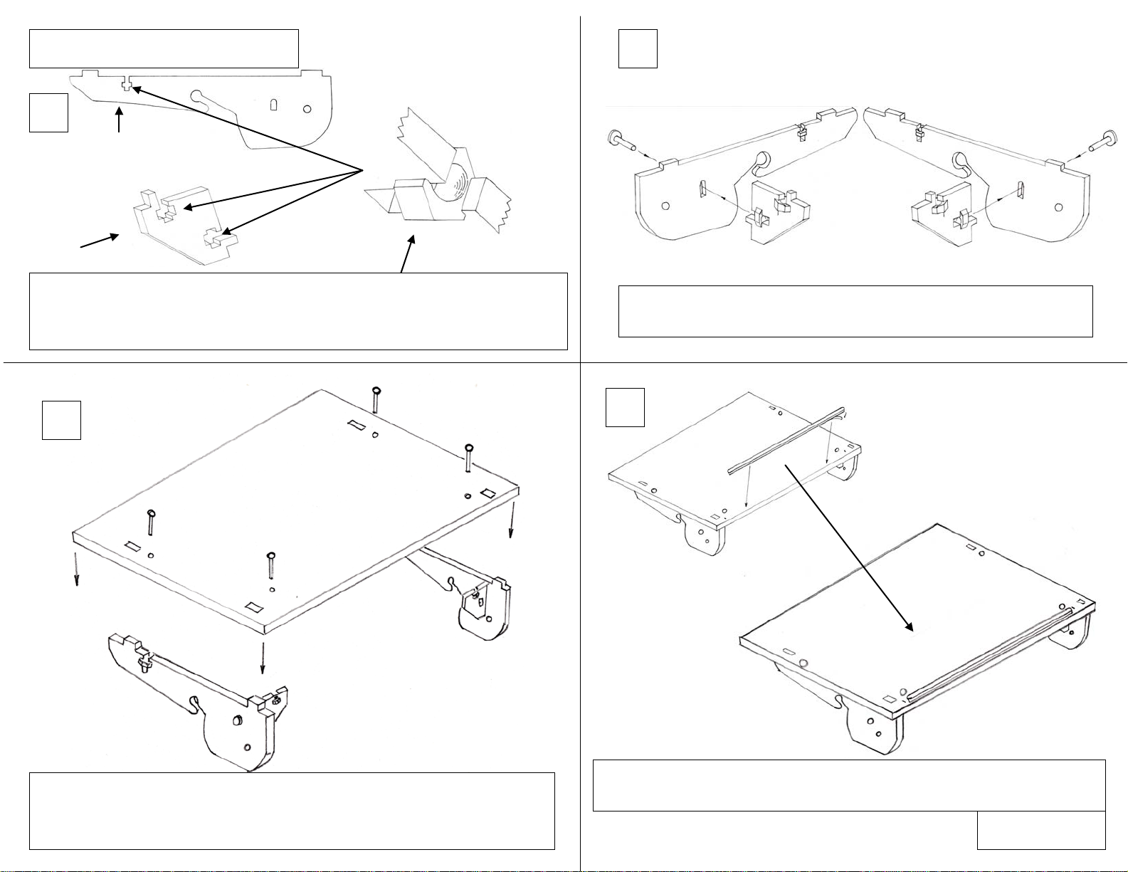
1
X 2 BRACE
X 2 SIDE
Secure the Brace sections to the Side sections as shown above
with the thumb screws provided.
Slide the plastic nuts into the slots in the Side and Brace sections. 1 nut in
Secure the Side/Brace assemblies to the underside of the main panel
Peel off the backing and secure the foam strip centrally along the front
edge. 2 Small lines are positioned in the main panel to guide you.
GO FLEX Instructions steps 1-7
TURN PAGE.
1 2 3
4
each Side and 2 in each Brace. If tight, simply press in from other side of
panel.
(Logo’s are on the top side). Position the lugs into the slots and secure
each side assembly with 2 screws.
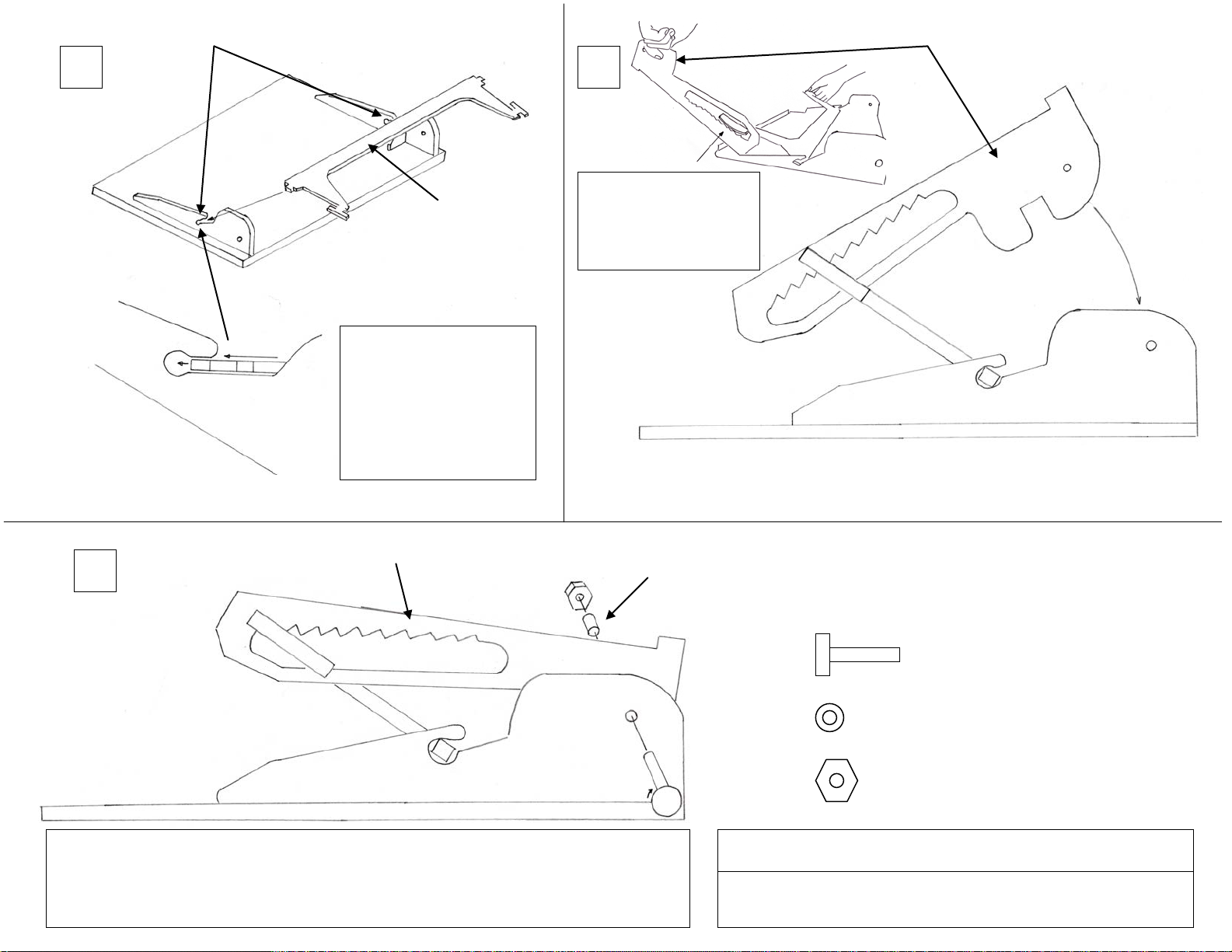
5 6 7
Pivot point
Slide the ends of the
straight side of the
Adjustment arm
Position a Leg over
both sides
Press the small cylindrical bush into the hole in the Leg, then secure the Leg to the
Turn the unit over and enjoy from the ergonomic benefits of your Go Flex.
Leg
Leg
Bush
You Tube assembly video: https://youtu.be/1VLyne6Fjb8
X6 Thumb Screw
X2 bush
X6 Nut
Parts list
WARNING. Product contains small parts and not suitable
for small children.
Adjustment Arm into
the Pivot Points in the
Main Panel/Sides
assembly and rotate.
the handle of the
Adjustment arm on
Side assemblies (on the inside face) with the remaining Thumb Screws and Nuts.
 Loading...