

Pin PointLocal Positioning Systems
Cell Controller
Inst allation Manual
W arnings 2
Included In This Package 3
About Antennas 4
Placement 5
Mounting 6
Inst alling 7
Technical Specification 7
' Copyright 1999, PinPoint Corporation. All right s reserved.
cc.qxd 5/5/99 4:28 PM Page 1
W arnings
Always place the Cell Controller in a well ventilated area.
Never block the Cell Controller s air vent s .
Keep the Cell Controller away from water.
Never attach the Antenna cables while the Cell Controller
is powered on! Equipment damage may result!
Do not overtighten the Coaxial Cables!
Do not kink or tightly bend the Coaxial Cables!
Changes and modifications not expressely approved by
PinPoint Corporation could void the user s authority to
operate the equipment.
Included in this p ackage
1 Cell Controller
1 AC power cord
2
Pin Po int Local Positioning Systems
Picture of Cell Controller
!
cc.qxd 5/5/99 4:28 PM Page 2
Inst alling Cell Controllers
About Cell Controllers
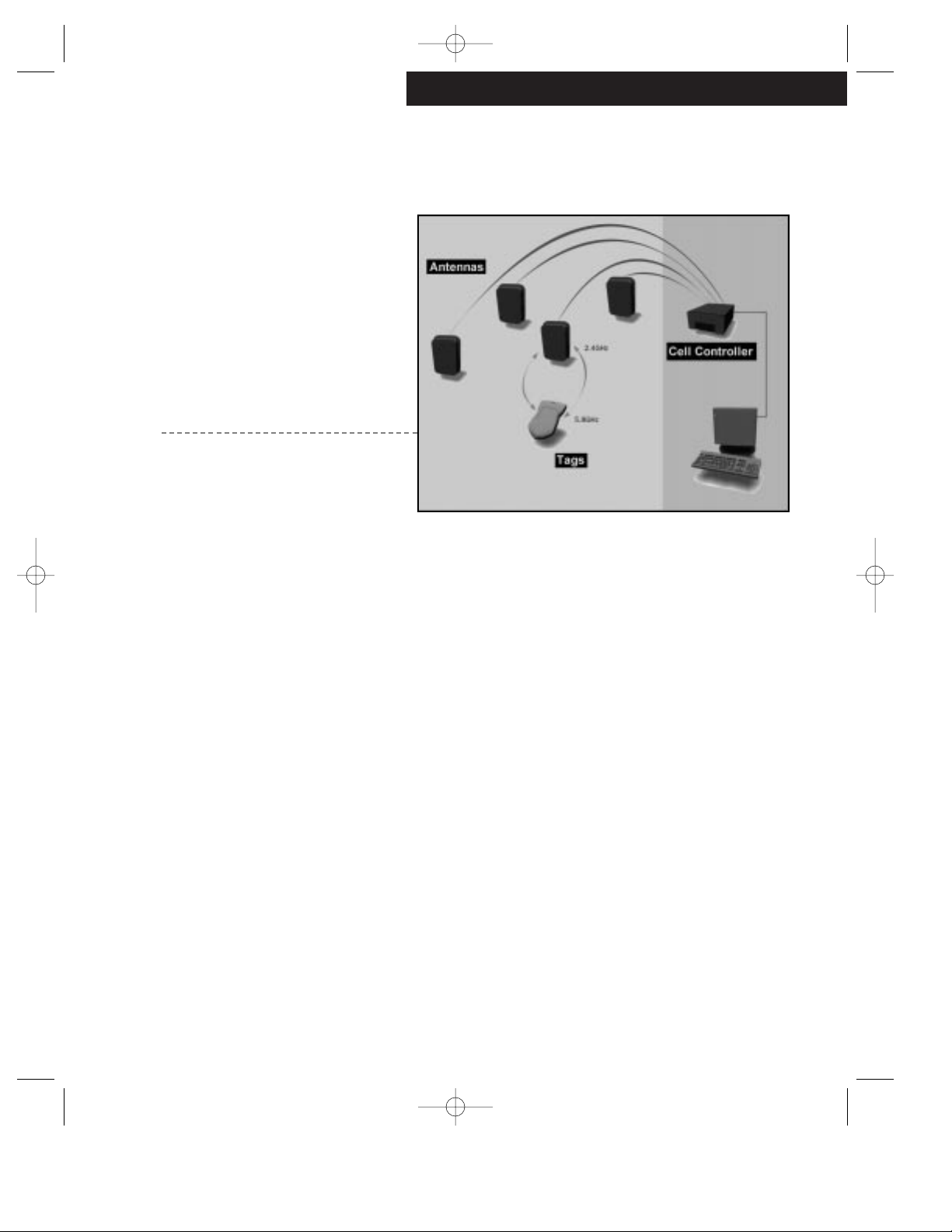
The Cell Controller is the primary data
collection tool of the 3D-iD system. The Cell Controller coordinates the Antennas broadcast s and then analyzes the signals returned by the Tags.
To do this, the Cell Controller broadcast s spread spectrum
signals at 2.44GHz to the 3D-iD Tags via it s att ached
Antennas. It then measures the total time transpired until
the return signals (at 5.77GHz) are received from the Tags.
Using this information it calculates the distance the Tag is
from the Antenna, called Tag Antenna Distance (TAD) dat a.
The Cell Controller sends the data it generates to the
V iewPoint Software via a st andard ethernet link. The soft ware will, using the data collected from several Antennas,
accurately determine a Tag s location.
3
cc.qxd 5/5/99 4:28 PM Page 3

Cell Controller Placement
The Cell Controller must be located sufficiently close to each of
it s antennas in order to account for a fixed cable length
(100 feet).
The Cell Controller must be located in proximity to a
st andard AC power outlet (grounded) and an appropriate
network jack.
The Cell Controller must be placed in a location with
adequate ventilation.
4
Pin Po int Local Positioning Systems
cc.qxd 5/5/99 4:28 PM Page 4

Inst alling Cell Controllers
Mounting the Cell Controller
The Cell Controller may be placed upon any sufficiently sturdy , f lat
surface such as a table or a desk. Remember to allow for
adequate ventilation.
Other Cell Controller mounts that may be purchased separately through your PinPoint sales representative are:
- Horizont al Mount
- Vertical Mount
- Durable Mount (NEMA rated for harsh environment s)
5
cc.qxd 5/5/99 4:28 PM Page 5

Inst alling the Cell Controller
1 . A t t ach the enclosed power cord to the AC outlet on the
Cell Controller. Plug the power cord into the wall outlet.
2 . At tach the appropriate network cable (ethernet) to the
Cell Controller. The ethernet cable should be connected
to the ViewPoint network.
3. A t tach up to 16 Antennas (depending upon the system
layout) to the antenna ports using the specified 3D-iD
Coaxial Cables (shipped separately). Att ach the
Antennas where indicated by your certified system integrator.
- Never attach the Antenna cables while the Cell
Controller is powered on! Equipment damage may
result!
- Do not overtighten the coaxial cables!
- Do not kink the coaxial cables!
4. Turn on the Cell Controller using the power switch. The
Cell Controller will enter a mode where it continuously
searches for the server software on the network.
6
Pin Po int Local Positioning Systems
Picture of rear of Cell
Controller, with cables.
cc.qxd 5/5/99 4:28 PM Page 6

Inst alling Cell Controllers
Maintaining the Cell Controller
Once operating, the Cell Controller will continue to function with
minimal maintenance.
Dust Screen
There is a permanent dust screen covering the ventilation
fan that should be checked every six months. If necessary,
the guard and screen should be removed, cleaned and
replaced. Be sure to power off the Cell Controller before
cleaning the screen.
Fuse
The Cell Controller s fuse (#313-xA 250V fuse) should be
replaced as necessary.
7
cc.qxd 5/5/99 4:28 PM Page 7

Pin Po int Local Positioning Systems
Technical Specifications
This device complies with Part 15 of the FCC Rules.
Operation is subject to the following two conditions: (1)
this device may not cause harmful interference, and (2)
this device must accept any interference received,
including interference that may cause undesired operat i o n .
Frequency:
Tx: 2.442 GHz
Rx: 5.770 GHz
Radiated Power: <1 W EIRP
AC Power: 110/220V AC, 50/60 Hz
Read Range: 125 feet
Performance: Detect a 3 second tag in a population of:
200 t ags within 10s (99% confidence)
500 t ags within 25s (99% confidence)
Dimensions: 18 x 9 x 6
Environment: -20 C 50 C (operating range)
5% - 95% humidity, no condensation
See Cell Controller Data Sheets for det ails
PinPoint Corporation
One Oak Park Bedford, MA 01730
http://www.pinpointco.com
phone/fax: 781-687-9720 - 781-687-9730
cc.qxd 5/5/99 4:28 PM Page 8
 Loading...