


RFL Electronics Inc.
INSTRUCTION MANUAL
RFL 9660
Digital Switch
NOTICE
The information in this manual is proprietary and confidential to RFL Electronics Inc. Any reproduction
or distribution of this manual, in whole or part, is expressly prohibited, unless written permission is
given by RFL Electronics Inc.
This manual has been compiled and checked for accuracy. The information in this manual does not
constitute a warranty of performance. RFL Electronics Inc. reserves the right to revise this manual and
make changes to its contents from time to time. We assume no liability for losses incurred as a result
of out-of-date or incorrect information contained in this manual.
Publication Number MC 9660
Printed In U.S.A.
Revised April 24, 2007 RFL Electronics Inc.
RFL 9660 RFL Electronics Inc.
April 24, 2007 i (973) 334-3100

WARRANTY
Except where noted, all RFL Electronics Inc. products come with a one-year warranty from date of delivery for
replacement of any part which fails during normal operation. RFL will repair or, at its option, replace components
that prove to be defective at no cost to the Customer. All equipment returned to RFL Electronics Inc. must have
an RMA (Return Material Authorization) number, obtained by calling the Customer Service Department. A
defective part should be returned to the factory, shipping charges prepaid, for repair or replacement FOB
Boonton, N.J.
RFL Electronics Inc. is not responsible for warranty of peripherals, such as printers and external computers. The
warranty for such devices is as stated by the original equipment manufacturer. If you have purchased peripheral
equipment not manufactured by RFL, follow the written instructions supplied with that equipment for warranty
information and how to obtain service.
WARRANTY STATEMENT
RFL Electronics Inc. products are warranted against defects in material and workmanship for one year from the
date of shipment. During the warranty period, RFL will repair or, at its option, replace components that prove to
be defective at no cost to the customer, except the one-way shipping cost of the failed assembly to the RFL
Customer Service facility in Boonton, New Jersey.
This warranty does not apply if the equipment has been damaged by accident, neglect, misuse, or causes other
than performed or authorized by RFL Electronics Inc.
This warranty specifically excludes damage incurred in shipment to or from RFL. In the event an item is
received in damaged condition, the carrier should be notified immediately. All claims for such damage should be
filed with the carrier.
NOTE
If you do not intend to use the product immediately, it is recommended that it be opened immediately
after receiving and inspected for proper operation and signs of impact damage.
This warranty is in lieu of all other warranties, whether expressed, implied or statutory, including but not limited
to implied warranties of merchantability and fitness for a particular purpose. In no event shall RFL be liable,
whether in contract, in tort, or on any other basis, for any damages sustained by the customer or any other
person arising from or related to loss of use, failure or interruption in the operation of any products, or delay in
maintenance or for incidental, consequential, indirect, or special damages or liabilities, or for loss of revenue,
loss of business, or other financial loss arising out of or in connection with the sale, lease, maintenance, use,
performance, failure, or interruption of the products.
RFL Electronics Inc.
353 Powerville Road
Boonton Township, NJ 07005-9151
RFL 9660 RFL Electronics Inc.
April 24, 2007 ii (973) 334-3100

CAUTION
FOR YOUR SAFETY
THE INSTALLATION, OPERATION, AND
MAINTENANCE OF THIS EQUIPMENT
SHOULD ONLY BE PERFORMED
BY QUALIFIED PERSONS.
WARNING:
The equipment described in this manual
contains high voltage. Exercise due care
during operation and servicing. Read the
safety summary on the reverse of this page
RFL 9660 RFL Electronics Inc.
April 24, 2007 iii (973) 334-3100

SAFETY SUMMARY
The following safety precautions must be observed at all times during operation, service, and
repair of this equipment. Failure to comply with these precautions, or with specific warnings
elsewhere in this manual, violates safety standards of design, manufacture, and intended use
of this product. RFL Electronics Inc. assumes no liability for failure to comply with these
requirements.
GROUND THE CHASSIS
The chassis must be grounded to reduce shock
hazard and allow the equipment to perform
properly. Equipment supplied with three-wire ac
power cables must be plugged into an approved
three-contact electric outlet. All other equipment
is provided with a rear-panel ground terminal,
which must be connected to a proper electrical
ground by suitable cabling. Refer to the wiring
diagram for the chassis or cabinet for the location
of the ground terminal.
DO NOT OPERATE IN AN
EXPLOSIVE ATMOSPHERE
OR IN WET OR DAMP AREAS
Do not operate the product in the presence of
flammable gases or fumes, or in any area that is
wet or damp. Operating any electrical equipment
under these conditions can result in a definite
safety hazard.
KEEP AWAY FROM
LIVE CIRCUITS
Operating personnel should never remove
covers. Component replacement and internal
adjustments must be done by qualified service
personnel. Before attempting any work inside the
product, disconnect it from the power source and
discharge the circuit by temporarily grounding it.
This will remove any dangerous voltages that
may still be present after power is
removed.
DO NOT SUBSTITUTE PARTS
OR MODIFY EQUIPMENT
Because of the danger of introducing additional
hazards, do not install substitute parts or make
unauthorized modifications to the equipment. The
product may be returned to RFL for service and
repair, to ensure that all safety features are
maintained.
READ THE MANUAL
Operators should read this manual before
attempting to use the equipment, to learn how to
use it properly and safely. Service personnel must
be properly trained and have the proper tools and
equipment before attempting to make adjustments
or repairs.
Service personnel must recognize that whenever
work is being done on the product, there is a
potential electrical shock hazard and appropriate
protection measures must be taken. Electrical
shock can result in serious injury, because it can
cause unconsciousness, cardiac arrest, and brain
damage.
!
Throughout this manual, warnings appear before
procedures that are potentially dangerous, and
cautions appear before procedures that may result
in equipment damage if not performed properly.
The instructions contained in these warnings and
cautions must be followed exactly.
RFL 9660 RFL Electronics Inc.
April 24, 2007 iv (973) 334-3100

TABLE OF CONTENTS
Title Page . . . . . . . . . . . i
Warranty . . . . . . . . . . . ii
High Voltage Warning . . . . . . . . . . iii
Safety Summary . . . . . . . . . . iv
Table Of Contents . . . . . . . . . . v
List Of Illustrations . . . . . . . . . . viii
List Of Tables . . . . . . . . . . . x
Trademarks . . . . . . . . . . . xi
List Of Effective Pages . . . . . . . . . . xii
Revision Record . . . . . . . . . . xiii
Section 1. PRODUCT INFORMATION
Section 2. INSTALLATION
2.1 INTRODUCTION . . . . . . . . . 2-1
2.2 UNPACKING . . . . . . . . . . 2-1
2.3 MOUNTING . . . . . . . . . . 2-2
2.4 VENTILATION . . . . . . . . . . 2-2
2.5 CONNECTIONS . . . . . . . . . 2-2
2.5.1 Making Connections To Terminal Blocks . . . . . . 2-2
2.5.2 Alarm, Remote Disconnect, Ground, And Power Connections . . . 2-4
2.5.3 Telephone Connections . . . . . . . . 2-7
2.5.3.1 Two-Wire Connections . . . . . . . 2-7
2.5.4 Rs-232 Port Connections . . . . . . . . 2-8
2.5.5 Connections To Direct Digital Interface . . . . . . 2-9
2.5.6 Fiber Optic Remote Mounting Dimensions . . . . . . 2-10
2.5.7 Connections To Fiber Optic Master And Remote Modules . . . . 2-11
2.6 SYSTEM EXPANSION . . . . . . . . . 2-13
Section 3. SWITCH AND PORT CONFIGURATION
3.1 INTRODUCTION . . . . . . . . . 3-1
3.2 CONTROLS AND INDICATORS . . . . . . . 3-1
3.3 MAKING CONNECTIONS TO THE LOCAL TERMINAL . . . . . 3-1
3.4 TURNING ON THE RFL 9660 . . . . . . . . 3-3
3.5 MASTER RESET . . . . . . . . . 3-4
3.6 LOCALLY ACCESSING THE RFL 9660 . . . . . . . 3-4
3.7 SETTING THE SITE ID . . . . . . . . . 3-7
3.8 SETTING PASSWORDS . . . . . . . . 3-8
3.9 ADDING CALLBACK STRINGS TO PASSWORDS . . . . . 3-11
3.10 SETTING PORT CONFIGURATIONS . . . . . . . 3-14
3.10.1 Entering the Port Configuration Mode . . . . . . 3-14
3.10.2 Setting The Port Label . . . . . . . . 3-16
3.10.3 Setting The Communications Parameters . . . . . . 3-16
3.10.4 Setting The Port Password . . . . . . . 3-17
3.10.5 Setting Port Flow Control . . . . . . . 3-17
3.10.6 Setting Callout Functions . . . . . . . . 3-19
3.10.7 Setting Special Port Configuration Functions . . . . . 3-21
3.10.8 Saving Your Port Configuration Settings . . . . . . 3-23
3.11 USING THE RFL 9660 AS A SUPER-USER . . . . . . 3-24
RFL 9660 RFL Electronics Inc.
April 24, 2007 v (973) 334-3100

TABLE OF CONTENTS - continued
Section 4. USING THE SWITCH
4.1 INTRODUCTION . . . . . . . . . 4-1
4.2 SETTING UP THE MODEM . . . . . . . . 4-1
4.3 USING MICROSOFT WINDOWS TO LOAD AND RUN APPLICATIONS . . . 4-1
4.4 USING THE MICROSOFT WINDOWS TERMINAL EMULATOR . . . . 4-3
4.5 WINDOWS 95 HYPERTERMINAL SETUP FOR USE WITH RFL 9660 DIGITAL SWITCH . 4-7
4.6 ACCESSING THE RFL 9660 . . . . . . . . 4-18
4.6.1 Remote Access Using The Microsoft Windows Terminal Emulator . . . 4-18
4.6.2 Remote Access Using A DOS-Based Terminal Emulator . . . . 4-22
4.6.3 Locally Accessing The RFL 9660 . . . . . . . 4-25
4.7 GENERAL ACCESS COMMANDS . . . . . . . 4-28
Esc - Abort Command . . . . . . . . . 4-30
H - Display Command List . . . . . . . . 4-30
D - Run Diagnostics . . . . . . . . . 4-30
I - Port Information . . . . . . . . . 4-30
Q - Quit Session . . . . . . . . . 4-32
Port #/Label - PORT SELECTION . . . . . . . 4-32
4.8 DESELECTING A PORT . . . . . . . . 4-33
4.9 CONNECTING THE LOCAL AND MODEM PORTS . . . . . 4-34
Section 5. CONFIGURATION COMMANDS
5.1 INTRODUCTION . . . . . . . . . 5-1
5.2 ACCESSING THE RFL 9660 AS A SUPER-USER . . . . . 5-1
5.3 SUPER-USER COMMANDS . . . . . . . . 5-1
H - Help . . . . . . . . . . 5-2
P - Program Port . . . . . . . . . 5-2
a - Label Port . . . . . . . . . . 5-5
b - Call Request . . . . . . . . . 5-6
c - Call Out . . . . . . . . . . 5-6
d - Password . . . . . . . . . . 5-6
e - Call String . . . . . . . . . . 5-7
f - Modem String . . . . . . . . . 5-8
g - Remote String . . . . . . . . . 5-9
h - Port String . . . . . . . . . . 5-9
i - Port Priority . . . . . . . . . 5-9
j - Local Port DTR . . . . . . . . . 5-10
k - Local Flow Control (XON/XOFF) . . . . . . . 5-10
l - Port Flow Control . . . . . . . . . 5-10
m - Communications Parameters . . . . . . . 5-11
q - Quit . . . . . . . . . . . 5-11
C - Configure The Switch . . . . . . . . 5-12
PP nn - Period Awaiting Password . . . . . . . 5-14
PA nn - Silence Before Deselect Code . . . . . . . 5-14
PB nn - Silence After Deselect Code . . . . . . . 5-14
PT nnnn - Inactive Period, Port Selected . . . . . . . 5-15
PM nnnn - Inactive period, menu mode . . . . . . . 5-15
CC xxx - Port Deselect Code . . . . . . . . 5-16
CB n x... - Callback String . . . . . . . . 5-16
PW n x... - Password . . . . . . . . . 5-17
CM x - Message Format . . . . . . . . . 5-17
CT x - Enable CCITT Modem Sequence . . . . . . . 5-18
CE x -Password Enable . . . . . . . . . 5-18
RFL 9660 RFL Electronics Inc.
April 24, 2007 vi (973) 334-3100

TABLE OF CONTENTS - continued
CS - Store Changes . . . . . . . . . 5-18
CA x - Enable Port Selection By Number . . . . . . . 5-19
Q - Quit programming mode without saving changes . . . . . 5-19
S - Show Current Selections . . . . . . . . 5-19
R - Reset To Factory Default . . . . . . . . 5-20
S - Save Changes . . . . . . . . . 5-21
R - Reset All Port Parameters To Default . . . . . . 5-21
U - Update Hardware Configuration . . . . . . . 5-22
Section 6. STATUS AND ERROR CODES . . . . . . . 6-1
Section 7. COMMAND LANGUAGE
7.1 B - SHORT-FORM RESPONSE . . . . . . . . 7-1
7.2 F - VERBOSE ASCII . . . . . . . . . 7-1
Section 8. SPECIAL JUMPER AND DIP SWITCH SETTINGS
8.1 INTRODUCTION . . . . . . . . . 8-1
8.2 CPU MODULE . . . . . . . . . . 8-1
8.3 MODEM MODULE . . . . . . . . . 8-5
8.4 RS-232 DEVICE PORT MODULE . . . . . . . 8-6
Section 9. FIBER OPTIC SET-UP INFORMATION
9.1 INTRODUCTION . . . . . . . . . 9-1
9.2 FIBER OPTIC MASTER I/O MODULE . . . . . . . 9-1
9.3 FIBER OPTIC REMOTE MODULE . . . . . . . 9-3
Section 10. MAINTENANCE
10.1 INTRODUCTION . . . . . . . . . 10-1
10.2 FUSE REPLACEMENT . . . . . . . . 10-1
10.2.1 Power Supply Fuse Replacement . . . . . . . 10-1
10.2.2 I/O Module Fuse Replacement . . . . . . . 10-3
10.3 FIBER OPTIC REMOTE MODULE FUSE REPLACEMENT . . . . 10-4
10.4 USING THE MODULE REMOVAL TOOL . . . . . . 10-6
10.5 DIAGNOSTICS . . . . . . . . . 10-7
10.6 HOW TO ARRANGE FOR SERVICE . . . . . . . 10-8
Section 11. GOVERNMENT REGULATIONS
11.1 FCC (United States) . . . . . . . . . 11-1
11.2 DOC (Canada) . . . . . . . . . . 11-2
Section 12. PORT ASSIGNMENTS . . . . . . . . 12-1
Section 13. MODEM "AT" COMMANDS AND "S" REGISTERS
13.1 INTRODUCTION . . . . . . . . . 13-1
13.2 MODEM "AT" COMMANDS . . . . . . . . 13-2
13.3 V.92 COMMANDS . . . . . . . . 13-19
13.4 S-REGISTERS 13-26
Section 14. PARTS LISTS AND SCHEMATICS . . . . . . . 14-1
Section 15. INDEX . . . . . . . . . . 15-1
Section 16. APPLICATION NOTES . . . . . . . . 16-1
RFL 9660 RFL Electronics Inc.
April 24, 2007 vii (973) 334-3100

LIST OF ILLUSTRATIONS
1-1. RFL 9660 Digital Switch . . . . . . . . . 1-1
1-2. Typical application, RFL 9660 Digital Switch . . . . . . . 1-3
2-1. Mounting dimensions, RFL 9660 Digital Switch . . . . . . 2-2
2-2. Rear view, RFL 9660 Digital Switch . . . . . . . . 2-3
2-3. RFL 9660 alarm, remote disconnect, and power connections (dc-powered units) . . 2-5
2-4. RFL 9660 alarm, remote disconnect, and power connections (ac-powered units) . . 2-6
2-5. Two-wire telephone connections, RFL 9660 Digital Switch . . . . . 2-7
2-6. Terminal assignments for PORT connectors on RFL 9660 Digital Switch . . . 2-8
2-7. Terminal assignments for direct digital connector on RFL 9660 Digital Switch . . . 2-9
2-8. Fiber optic remote mounting dimensions . . . . . . . 2-10
2-9. Fiber optic connections between master and remotes in fiber optic ring . . . 2-11
2-10. Power connections between three fiber optic remotes at the same site . . . 2-12
2-11. General installation and interfacing information, RFL 9660 Digital Switch . . . 2-15
3-1. Controls and indicators, RFL 9660 Digital Switch . . . . . . 3-2
3-2. Construction details for cable between local terminal and LOCAL connector
on RFL 9660 Digital Switch . . . . . . . . 3-3
3-3. List of super-user commands . . . . . . . . 3-5
3-4. Relationship between commands used for switch and port configuration . . . 3-6
3-5. Typical configuration command list display . . . . . . . 3-9
3-6. Typical list of current selections with passwords entered . . . . . 3-10
3-7. Typical list of current selections with passwords and callback strings entered . . 3-13
3-8. Typical port information display, showing factory default values . . . . 3-14
3-9. Typical port information display with list of selections . . . . . 3-15
4-1. Microsoft Windows "Terminal Emulator" window . . . . . . 4-3
4-2. "Terminal Emulation" dialog box for Microsoft Windows Terminal Emulator . . . 4-3
4-3. "Terminal Preferences" dialog box for Microsoft Windows Terminal Emulator . . . 4-4
4-4. "Communications" dialog box for Microsoft Windows Terminal Emulator . . . 4-5
4-5. "Modem Commands" dialog box for Microsoft Windows Terminal Emulator . . . 4-6
4-6. "Phone Number" dialog box for Microsoft Windows Terminal Emulator . . . 4-6
4-7. HyperTerminal window . . . . . . . . . 4-8
4-8. Connection description window . . . . . . . . 4-8
4-9. Phone number window . . . . . . . . . 4-9
4-10. Connect window . . . . . . . . . . 4-10
4-11. Properties/phone number window . . . . . . . . 4-10
4-12. Modem properties/general window . . . . . . . 4-11
4-13. Modem properties/connection window . . . . . . . 4-12
4-14. Advance port settings window . . . . . . . . 4-13
4-15. Advanced connection settings window . . . . . . . 4-13
4-16. Modem properties/options window . . . . . . . . 4-14
4-17. Properties/settings window . . . . . . . 4-15
4-18. Terminal settings window . . . . . . . . . 4-16
4-19. ASCII setup window . . . . . . . . . 4-16
4-20. Connect window . . . . . . . . . . 4-17
4-21. Typical general access command list display . . . . . . 4-20
4-22. Relationship between general access commands . . . . . . 4-20
4-23. Typical general access command list display . . . . . . 4-23
4-24. Typical port summary table . . . . . . . . 4-24
RFL 9660 RFL Electronics Inc.
April 24, 2007 viii (973) 334-3100

LIST OF ILLUSTRATIONS - continued
4-25. Typical general access command list display . . . . . . 4-26
4-26. Typical port summary table . . . . . . . . 4-27
4-27. Typical general access command list display . . . . . . 4-28
4-28. Relationship between general access commands . . . . . . 4-29
4-29. Typical port summary table . . . . . . . . 4-31
5-1. Typical super-user command list display . . . . . . . 5-2
5-2. Relationships between super-user commands . . . . . . 5-3
5-3. Typical port information display, showing factory default values . . . . 5-4
5-4. Typical port information display with list of selections . . . . . 5-5
5-5. Typical configuration command list display . . . . . . . 5-12
5-6. Typical list of current selections . . . . . . . 5-20
5-7. Typical port configuration display . . . . . . . . 5-22
8-1. Programmable jumpers and DIP switches, CPU module . . . . . 8-2
8-2. Programmable jumpers and DIP switches, RFL 9660 modem module . . . 8-5
8-3. Programmable jumpers, RS-232 device port module . . . . . . 8-6
9-1. Programmable DIP switches and indicators, fiber optic master I/O module . . . 9-2
9-2. Programmable DIP switches and indicators, fiber optic remote module . . . 9-3
10-1. Typical diagnostic test display . . . . . . . . 10-7
14-1. Component locator drawing, RFL 96 CPU Central Processor (CPU) Module . . 14-6
14-2. Schematic, RFL 96 CPU Central Processor (CPU) Module . . . . 14-7
14-3. Component locator drawing, RFL 9600 Modem . . . . . 14-12
14-4. Schematic, RFL 9600 Modem . . . . . . . 14-13
14-5. Component locator drawing, RFL 9600 Modem I/O . . . . . 14-14
14-6. Schematic, RFL 9600 Modem I/O . . . . . . . 14-15
14-7. Component locator drawing, RFL 96 DTE I/O Direct Digital I/O Module . . . 14-17
14-8. Schematic, RFL 96 DTE I/O Direct Digital I/O Module . . . . . 14-19
14-9. Component locator drawings, dc-input power supply modules for RFL 9660 Digital Switch . 14-25
14-10. Schematic, input board, dc-input power supply modules for RFL 9660 Digital Switch . 14-27
14-11. Component locator drawings, ac-input power supply module for RFL 9660 Digital Switch . 14-33
14-12. Schematic, ac-input power supply module for RFL 9660 Digital Switch . . . 14-35
14-13. Component locator drawing, RFL 96 PWR/ALARM I/O Power/Alarm I/O Module . . 14-38
14-17. Schematic, RFL 96 PWR/ALARM I/O Power/Alarm I/O Module . . . . 14-39
14-18. Component locator drawing, RFL 96 AC/ALARM I/O Ac-Input Power/Alarm I/O Module . 14-42
14-19. Schematic, RFL 96 AC/ALARM I/O Ac-Input Power/Alarm I/O Module . . . 14-43
14-20. Component locator drawing, RFL 96 MSM I/O RS-232 Device Port Module . . 14-46
14-21. Schematic, RFL 96 MSM I/O RS-232 Device Port Module . . . . . 14-47
14-22. Component locator drawing, fiber optic master I/O module for RFL 9660 Digital Switch . 14-53
14-23. Schematic, fiber optic master I/O module for RFL 9660 Digital Switch . . . 14-55
14-24. Component locator drawing, motherboard for RFL 9660 Digital Switch . . . 14-58
14-25. Schematic, motherboard for RFL 9660 Digital Switch . . . . . 14-59
14-26. Component locator drawing, fiber optic remote module transceiver board . . . 14-63
14-27. Schematic, fiber optic remote module transceiver board . . . . . 14-65
14-28. Component locator drawing, fiber optic remote module power supply board . . 14-68
14-29. Schematic, fiber optic remote module power supply board . . . . . 14-69
RFL 9660 RFL Electronics Inc.
April 24, 2007 ix (973) 334-3100

LIST OF TABLES
2-1. DIP switch settings for fiber optic remote module addressing . . . . . 2-14
3-1. Controls and indicators, RFL 9660 Digital Switch . . . . . . 3-2
5-1. Configuration setting worksheet, RFL 9660 Digital Switch . . . . . 5-13
7-1. Short-form responses and long-form equivalents . . . . . . 7-2
7-2. Long-form responses and short-form equivalents . . . . . . 7-3
8-1. DIP switch settings for local port setup . . . . . . . 8-2
8-2. DIP switch settings for modem port setup . . . . . . . 8-3
8-3. DIP switch settings for direct digital port setup . . . . . . 8-3
9-1. DIP switch settings for fiber optic remote module addressing . . . . . 9-4
10-1. Fuse replacement data, RFL 9125 power supply modules . . . . . 10-2
10-2. Fuse replacement data, RFL 9660 fiber optic remote modules . . . . 10-4
12-1. Device port totals and port numbers, RFL 9660 Digital Switch . . . . 12-1
12-2. Device port assignments, RFL 9660 Digital Switch . . . . . . 12-3
13-1. Modem "AT" Commands . . . . . . . . . 13-3
13-2. RFL 9660 modem module “S” register summary . . . . . . 13-26
13-3. Result codes . . . . . . . . . . 13-29
14-1. Replaceable parts, RFL 96 CPU Central Processor (CPU) Module . . . . 14-3
14-2. Replaceable parts, RFL 9660 Modem . . . . . . . 14-11
14-3. Replaceable parts, RFL 9660 Modem I/O . . . . . . 14-14
14-5. Replaceable parts, RFL 96 DTE I/O Direct Digital I/O Module . . . . 14-16
14-6. Replaceable parts, dc-input power supply modules for RFL 9660 Digital Switch . . 14-21
14-7. Replaceable parts, ac-input power supply module for RFL 9660 Digital Switch . . 14-31
14-8. Replaceable parts, RFL 96 PWR/ALARM I/O Dc-Input Power/Alarm I/O Module . . 14-37
14-9. Replaceable parts, RFL 96 AC/ALARM I/O Ac-Input Power/Alarm I/O Module . . 14-41
14-10. Replaceable parts, RFL 96 MSM I/O RS-232 Device Port Module . . . 14-45
14-11. Replaceable parts, fiber optic master I/O module for RFL 9660 Digital Switch . . 14-51
14-12. Replaceable parts, motherboard for RFL 9660 Digital Switch . . . . 14-57
14-13. Replaceable parts, fiber optic remote module transceiver board . . . . 14-61
14-14. Replaceable parts, fiber optic remote module power supply board . . . 14-67
RFL 9660 RFL Electronics Inc.
April 24, 2007 x (973) 334-3100

TRADEMARKS
"CrossTalk" is a registered trademark of Microstuf, Inc.
"DDP" and "D-Link" are registered trademarks of the General Electric Company.
"Hayes AT" is a registered trademark of Hayes Corporation.
"JAV" and "JEM-2" are registered trademarks of Scientific Columbus.
"LFCB" is a registered trademark of the General Electric Company Plc of England.
"MDAR," "MINT," "PONI," and "WRELCOM" are registered trademarks of ABB Brown-Boveri.
"MNP" is a registered trademark of Microcom, Inc.
"Opticom" and "Optimho" are registered trademarks of GEC Alsthom, T&D Inc.
"Procomm Plus" is a registered trademark of Datastorm Technologies, Inc.
"Quantum" and "Mini-Pro" are registered trademarks of Schlumberger Industries Inc.
"Windows" and "Word" are registered trademarks of Microsoft, Inc.
"WordStar" is a registered trademark of MicroPro International Corporation.
The trademark information listed above is, to the best of our knowledge, accurate and complete.
RFL 9660 RFL Electronics Inc.
April 24, 2007 xi (973) 334-3100

LIST OF EFFECTIVE PAGES
When revisions are made to the RFL 9660 Instruction Manual, the entire section where revisions were made is
replaced. For the edition of this manual dated April 24, 2007 the sections are dated as follows:
Front Matter April 24, 2007
Section 1 Latest version of Product Information sheet
Section 2 April 24, 2007
Section 3 October 1, 1999
Section 4 April 24, 2007
Section 5 August 18, 1998
Section 6 August 18, 1998
Section 7 August 18, 1998
Section 8 April 24, 2007
Section 9 April 24, 2007
Section 10 August 18, 1998
Section 11 April 24, 2007
Section 12 August 18, 1998
Section 13 April 24, 2007
Section 14 April 24, 2007
Section 15 April 24, 2007
Section 16 October 1, 1999
RFL 9660 RFL Electronics Inc.
April 24, 2007 xii (973) 334-3100

REVISION RECORD
Rev Description Date Approval
02-25-94 New Document Release
10-24-94 Revised in accordance with ECO number(s) 9660-056,
-058, -062, -068, and RFA number 2942
02-15-95 Revised in accordance with ECO number 9660-072.
Effected pages: i, v, xi, xii, xiii, Section 16
10-18-96 Revised in accordance with ECO number 9660-076 and
077. Added 14.4 modem and new CPU
04-16-97 Revised in accordance with ECO number 9660-084.
Added new Product Information sheet.
11-26-97 Revised in accordance with RFA number 5503, and ECO
numbers 9660-085, 087, 088, 089, 090, 091. Replaced
14.4 modem with 28.8 modem, revised fiber optic
master, power/alarm I/O, modem I/O, and updated
product information sheet.
04-30-98 Revised in accordance with RFA numbers 5085, 5636
and 5642 and ECO numbers 9660-093, 095 and 096.
Added HyperTerminal setup, added Application notes
001A and 029
08-18-98 Converted text from WordStar to Word, added paragraph
numbers, upgraded HyperTerminal, deleted reference to
RFL bulletin board.
03-30-99 Revised in accordance with RFA numbers 6310 and
6359. Added Application note 030 and revised
Application notes 001, 003, 005, 006, 009, 016, 022 and
025.
RFL 9660 RFL Electronics Inc.
April 24, 2007 xiii (973) 334-3100

REVISION RECORD - continued
Rev Description Date Approval
10-01-99
4-24-07 Manual revised to change to new modem. Section 2, 4,
Revised in accordance with RFA numbers 6191, 6198
and 6802. Revised in accordance with ECO number
9660-097. Added Application Notes 9660-030 and
9660-031.
8, 9, and 11 has minor changes, Section 13 and 14 is
completely new. Modified for pdf production.
4-24-07
TG
RFL 9660 RFL Electronics Inc.
April 24, 2007 xiv (973) 334-3100

RFL
Electronics Inc.
RFL
9660
Digital Switch
I
I
"One Phone Line Connects
All
Substation Devices"
The RFL 9660 Digital Switch provides a convenient way to connect intelligent relays, smart meters, sequenceof-event recorders, digital fault recorders (DFRs), or similar devices to a central intelligent digital switch.Through
the use of third-party software packages, the RFL 9660 is able to communicate with Intelligent Electrical
Devices
(IED's). Once connected, the user can access and interrogate up to 32 individually
programmable RS-232 ports. This allows maintenance personnel to instantly access substations from their
desks, without having to make a field trip.
Only a single phone line is required to connect to the RFL 9660; this reduces the number of phone lines
required for polling substation equipment.
By
replacing the internal modem with a direct digital interface, the
RFL 9660 can also be connected to an existing substation digital network.
October
1,
2000
1
Publication No. PI9660

Front view.
RFL
9660
Diaital Switch
Regular telephone line sharing switches require a
separate modem at each device. For example, an
installation with eight devices would require eight modems.
To eliminate expensive modem costs, the RFL 9660 has
been designed to contain its own integrated modem. It's
all that's needed to interface all your recorders, relays,
solid-state meters, or similar equipment.
The RFL 9660 eliminates:
Separate phone lines
Individual telephone modems
Expensive modem installation and
maintenance costs.
RFL continues to develop Application Notes for a variety
of substation devices:
ABB DPU Relay
ABB MDAR Relay (With
PONI or MINT Module)
GEC Optimho Relay
General Electric DDP Relay
General Electric DLP Relay
Hathaway Fault Recorder
Mehta Tech
Transcan Digital Recorder
Metrosonics Model RV-2 Recording Voltmeter
Metrosonics Model RV-3 Recording Voltmeter
Metrosonics Model SRV-3 Recording Voltmeter
NEI
Duobias Fiber Modem
NEI Microphase Fiber Modem
RFL
6720P Checkback System
The RFL 9660's power supply, control inputs, and alarm
RFL 9001 Intelligent ~ulti~lexer
relay outputs are designed to comply with the Surge
RFL IMUX 2000 Intelligent Multiplexer
Withstand and Fast Transient requirements of ANSI
RFL 9300 Charge Comparison System (CCS)
C.37.90.1 and C.37.90-1978. In addition, RFL 9660
RFL 9700 Digital Protection Channel
operation is guaranteed at temperatures from -30°C to
RFL 9720 Pilot Wire Interface
+60°C (-22°F to + 140°F).
RFL 9745 Teleprotection Channel
Schlumberger Industries Quantum Meter
Schweitzer Engineering Series 100 Relay
Schweitzer Engineering Series 200 Relay
Schweitzer Engineering Series 300 Relay
Scientific Columbus JEM-2 Multifunction Meter
Note:
If
you have a device that
is
not on this list,
please contact the factory
-
an Application Note will
be developed
rr\
October
1,2000
Publication No. PI9660

Rear view, RFL
9660
Digital Switch
Two types of
RFL
9660 device port modules are
available:
RS-232
and fiber ring. Each
RS-232
device
port module will accommodate up to eight individual
devices, such as relays or meters. Up to four
RS-232
device port modules can be installed in one
RFL
9660
and can access up to
32
devices. A typical
RS-232
device port module is shown below.
The fiber optic device port module allows up to
32
devices to be connected on to a fiber optic ring. An
RFL
9660 can be equipped with both
RS-232
and
fiber optic device port modules. The total number of
device connections cannot exceed
32.
RS-232 Device Port Module
.t
October
1,2000
3
Publication
No.
PI9660

In order to prevent unauthorized access, the RFL 9660
features three different levels of security and an
access alarm output. In the first level of security, each
device port can be protected with a password. The
second level adds a log-on password that must be used
when the switch is first called. The third level has a
callback feature that causes the RFL 9660 to call the
user back at a preset telephone location before
access is allowed.
Any installation where isolation from ground
potential rise is important.
Any installation where ambient noise levels
are high.
Any installation where it is difficult to run
RS-232 cables.
Any installation where distances greater than those
recommended by RS-232 must be covered.
Passwords are assigned by a designated "super-user."
Any time the RFL 9660 is accessed (either remotely
or locally), an access alarm relay contact
will close. The RFL 9660 is available with a built-in 28.8 bps
These contact closures can be externally monitored modem that is Ha~es-com~atible and complies with
or logged.
CCITT V.34 bis and Bell 212A. By replacing this
modem with a direct digital interface, an external
All port configuration is software-controlled and configuration parameters can be re-programmed locally
or remotely. New values are stored in the RFL 9660's
non-volatile memory so configurations will be retained
even during loss of power.
fer rates up to
19.2
kbs.
Each device port on the RFL 9660 can be individually
RFL
96
0%
FIBER
OPTIC
REMOTE
FIBER
:..I
DATA
ACT
lVE
ADDRESS
--.
:;;;.-;;;.-;;
:
I
--.
?*..
,'.
. .
. .
.
..
-
,.........).
--
-
--
----
-
.
*L
programmed to match the requirements of the device
connected to it. Ports can be given physical names
and functions such as baud rate, parity, number of data
bits, and types of flow control can be individually
programmed.
The RFL 9660 can communicate over a fiber optic loop
when it is equipped with a fiber optic master 110
Typical fiber optic remote transceiver module
module. A separate fiber optic remote transceiver
17
module connects each device to the fiber loop. Using
When
working
at
the
substation, a local
RS-232
port
multimode fiber and ST-type connectors, the loop
operates at 850 nm.
is available on the front of the RFL 9660. This allows
you to configure the system or interrogate devices in
the substation by
con-netting
a terminal or portable
PC directly to the RFL 9660. While the modem is in
use, access to the RFL 9660 through the local
RS-232 port is denied.
October
1,
2000
Publication
No.
PI9660

Remote users can access the
RFL
9660 by using PC's
with a 286 (or better) processor and a
Hayes-compat-
ible modem. A mouse is optional, but its presence will
simplify use. The PC must be running DOS
3.1
(or better), with Microsoft Windows Version
3.1
(or
better) installed. Microsoft Windows is recommended,
because of its multi-tasking capabilities. The
RFL
9660
also accommodates access by a dumb terminal or with
most PC terminal emulation programs.
The
RFL
9660 is compatible with the Microsoft
Windows Terminal Emulation Program. This allows
user-friendly access to all
RFL
9660 functions. It also
gives you the ability to conveniently run
device-
specific DOS-based programs once the
RFL
9660
selects a port. By using the Windows terminal
function keys, user-programmable events can be
invoked with a mouse.
Once the switch is accessed, a simple ASCII com-
Port
#2
3rd & Main St. Relay
Interface -RS232 Call Out
-
Off
Baud Rate
-2400
Call Request - None
Data Bits
-8
Call Priority
-
0
Parity-None Call String
-
Stop Bits
-
1
Remote String
-
Port Flow Ctrl -None Port String
-
LocalPortDTR
-ON
Modem String-
Local Flow Ctrl -ON Port Password-
To change type
Y:-
a - Label port
b - Call request
c - Call out d - Password
e
-
Call string
f
-
Modem string
g
-
Remote string
h
-
Port string
i
-
Port
priority
j
-
Local port DTR
k
-
Local flow ctrl (xonlxoff)
I
-
Port
flow
ctrl
m - Communications params
q - Quit
PORT 2>
-
-
mand language is used to communicate with the
RFL
9660. Typical display screens seen during access are
shown on this page.
Esc -Abort command
H
-Help
D
-Run diagnostics
I
-Port information
Q
-Quit session
Port #/Label -Port selection
P
-Program port
C
-Configure switch
S
-Save changes
R
-Reset
port parameters
U
-Update hardware configuration
Modem
-Connect local port to modem port
Local>
-
When the
RFL
9660 is powered up, it conducts a full
self-test routine. A built-in watchdog timer can trigger
a system reset and communicate a failure alarm. The
diagnostics can be run at any time, either from a
terminal connected to the local port on the front of the
RFL
9660, or from a remote terminal.
The
RFL
9660 includes a redundant
RJ-11
telephone
jack. This allows the
RFL
9660 to share an extension
with a telephone.
The
RFL
9660's emergency interrupt signalling can
be used to interrupt a call into the
RFL
9660 if the
phone needs to be used in an emergency. In addition,
interrupt signaling can give another user priority
access to the
RFL
9660.
October
1,
2000
5
Publication No. PI9660

Port Configuration: Each port parameter is remotely or
locally programmable.
The RFL 9660's internal or external modem may be
reconfigured when a port is selected. The RFL 9660 can
send a pre-programmed
"AT"
command string to the
modem upon port selection. This command string can
be used to turn flow control on or off, or to change any
Communications Parameters:
Data Rate: 300, 1200,2400,4800, 9660, or 19.200 bps.
Number of Data Bits: Seven or Eight
Parity: Odd, Even or None
Number of Stop Bits: One or Two
modem parameter to accommodate the device con-
Flow Control: RTSICTS, DTRIDSR, XONIXOFF, or None
nected to that port.
Originate Call: Hayes AT-compatible command string, up
to 40 characters long.
Each port can sense an active RTS (Request-ToSend)
Port
Name:
Up
to
30
characters,
or DTR (Data-Terminal-Ready) signal on the RS-232
connector. This allows an end device to initiate a call out
Port Priority: Ten levels (0 through 9), with Level 9 given
of the station to a pre-programmed location. One phone
the highest priority.
number can be stored for each port.
Port Password: A different seven-character password can
be stored for each port.
Each RFL 9660 switch is housed in a chassis three rack
units high (5.25 inches, or 13.3 cm). The RFL 9660's
circuit board modules plug into the front of the chassis,
Connector
Type:
Female
g-pin
D-Subminiature
(DE-9),
and
its
'I0
plug
into
the
back'
A
mother board
EIA 574compafible. Mounted on front panel, configured
between the circuit board modules and the I10 modules,
as a DCE.
makes all interconnections between modules. External
equipment
'Onnects
to
the
RFL
9660
through
the
Programming: DIP switches set port for 1200, 2400,
terminal blocks, telephone jacks, and RS-232 or fiber
4800, or 9600 bps, with Odd, Even, or No Parity.
optic connectors on the rear panel.
Flow Control: XONJXOFF
Number of Data Bits: Eight
Maximum Number: 8,16,24,32, asynchronous RS-232
data ports, depending on the number of device port
Number of Stop Bits: One or Two
modules installed.
Port Configuration: All device ports are configured
as
DCE's.
Connector Type: Male 9-pin D-subminiature (DE-9), EIA
574-compatible.
October
1,
2000
6
Publication No. PI9660

Type: Locally-programmable; fully-automatic auto-dial
FCC Registration: Modem module designed in
accordance with FCC Part 68 rules.
FCC Registration Number: B46USA-30667-FA-E
Ringer Equivalence: 0.6B
Interface: EIA RS-232DlCCITT V.34
Data Format: Asynchronous Serial Binary
Number of Data Bits:
With Parity: Seven or Eight
Without Parity: Eight
Number of Stop Bits: One or Two.
Maximum Data Rate: CCITT V.34 bis: 28.8 kbps to
DTE 1 15,200.
Data Compression: Automatic
Error Correction: Automatic
Command Set: Extended Hayes "AT" command
set and responses.
Command Buffer: 40 characters.
Dialing Capability:
Tone Dialing: Digits 0 through 9, A,B,C,D,
*,
and
#.
Pulse Dialing: 9.5 to 10.5 pulses per second
(PPS)
Transmit Level: -1 0dBm
Receive Level: -43 to -1 0 dBm
110 Module: Two-wire dial-up
**
Direct Digital Interface (non-modem units):
Type: RS-232 data port configured as a DTE.
Connector Type: male 25-pin D-Subminiature
(DB-25)
Port Configuration:
Data Rate: Switch-selectable to 300, 1200,
2400,4800, 9600, 19,200 or 28,800 bps.
Parity: Odd, Even, or None
Number of Data Bits: Seven or Eight
Flow Control: XONIXOFF
Standards Compliance: Designed to meet the requirements of ANSI
C37.90-1978 and ANSI C37.90.1
Switch Fail Alarm: Form "Cn contact, rated for 100 mA
at 142 Vdc
Access Alarm: Form "C" contact, rated for 100 mA at
142 Vdc
Remote Disconnect Input: Optically isolated, 48 to 142
Vdc operation
**
For 4-wire applications the 2400 baud modem
and 4W 110 must be used.
October
1,2000
7
Publication
No. PI9660

Power Supply: 25-Watt output, input voltage of 24 Vdc,
48 Vdc, 125 Vdc, 250 Vdc, 1 10
Vac, or 220 Vac. Each
power supply meets the Surge Withstand and Fast
Transient Protection requirements of ANSl C37.90-1978
and C37.90.1.
Current Draw: The RFL 9660 typically draws 350 mA
from its power supply, plus an average of 15 mA for each
device port module when the RFL 9660 is in the idle
state. When a port is in use, an additional 15
mA will
typically be drawn from the supply.
Operating Temperature: -30°C to +65"C
(-22°F to + 1 4g°F)
Device Port:
Configuration: DCE. Each port parameter can be
programmed through the RFL 9660.
Connector Type: Male 9-pin D-Subminiature
(DE-9), EIA 574-compatible.
Data Rate: 300, 1200, 2400, 4800, 9600, or
19,200 bps.
Number of Stop Bits: One or Two
Flow Control:
RTS/CTS, DTR/DSR, XONIXOFF, or
None.
Fiber Optic Connector Type: ST
Fiber Type: 62.5-micron, 850-nm, multimode
Relative Humidity: Up to 95 percent at +40°C, non- Transmission Distance: Each fiber optic link can be up
condensing
to 2 kilometers long (6,560 feet)
Dimensions:
Height: 5.25 inches (1 3.3 cm)
Depth: 13 inches (33.0 cm)
Width: 19 inches (48.3 cm)
Weight: Approximately 15 Ibs (6.2 kg).
Windows Application Requirements:
Computer: IBM PC or compatible, with a 286 processor
(or better).
Operating System: DOS 3.1 or better, running
Microsoft Windows Version 3.1 (or better).
Optical Power Budget: 8 dB per link
Pulse Modulation Encoding Format: Manchester II.
Input Power: 9 Vdc, 48 Vdc, or 125 Vdc. The 48 Vdc and
125 Vdc inputs meets the Surge Withstand and Fast Transient Protection requirements of ANSl C37.90-1978 and
ANSl C37.90.1
Current Draw: 350 mW typical
Operating Temperatures: -30°C to +70°C
(-22°F to 158°F)
Relative Humidity: Up to 95 percent at +40°C,
noncondensing
Dimensions:
Length: 6 inches
(1
5.2 cm)
Width: 4 inches (1 0.2 cm)
Height: 2.0 inches (5.1 cm)
October 1,2000
8
Publication
No.
PI9660

RFL 9660 Digital Switches are ordered by specifying the power supply input voltage, modem type, number of RS-
232 device port modules required, whether a fiber optic device port module is required, and chassis type. The
choices are specified by using the following part number scheme.
Power-Supply _Input:
24 Vdc
48 Vdc
125 Vdc
110
Vac
220 Vac
250 Vdc
Communciations
Direct Digital Interface
V.34 Modem
&
2-Wire I10
V.22 Modem & 4-Wire 110
Number of
RS-232
Device Port Modules:
1
(For up to 8 RS-232 devices)
1
I
2 (For up to 16 RS-232 devices)
2
3
(For up to 24 RS-232 devices)
3
4 (For up to 32 RS-232 devices)
'
-----
4
----------------
- -
- - - - -
- -
........................
-
- - - - - - -
-
Fiber Optic Master:
'
Not Installed
Installed
Chassis Mounting:
Flush Mount
Projection Mount
Fiber Optic Remote:
Without Internal Power Supply:
With Internal Power Supply:
48 Volt Input:
125 Volt Input:
Order No. 104870-1
Order No. 104870-2
Order No. 104870-3
Notes:
The fiber master occupies one horizontal device port slot in the rear of the RFL 9660. If a fiber optic master
-
- -
is
installed,-only th-ree RS:=DeqePort
- -
-
Modules
- - -
can be installed.
--
-
--
---
- - -
-
----------------
-
- - - - - -
- -
One fiber optic remote is required for each fiber optic device being interfaced to the RFL 9660. Up to 32
fiber optic
remotes can be used. Fiber optic cabling between the RFL 9660 and the fiber optic remote is not
normally supplied.
Up to two fiber optic remotes without power supplies may be powered from one with a power supply.
October
1,
2000
Publication
No.
PI9660

Rear view, RFL
9660
Digital Switch
.'1
/
//
MODEM
Vl2-kr
DIAL-UP MODEM
6zmmsL
REMOTE
OfFKE
K
-
-
- -
- - - - -
- - -
-
-
-
-
-
-
- - -
I
TELEPHONE
--I
CONNECtlON
I
I
I
RJ-11
I
+
FAILURE ALARM MODEM
I
RTU
m-
I
ACCESS
AURM
I
I
DISCONNECT
I
I
I
15-232 DEVICE
ABER OPTlC
I
I
DMCE URD
-
I
I
PORT0
...
PORT7
-
TX
RX
I
I
A A
tA
...
I
DIGITAL
,
I
RELAY
I
I
BREAKER I 1
I
I
-[RELAY]
I
I
FIBER
I
BREAKER I2
OKlC
I
FIBER
OPTIC
I
REMOTE
I
CONTROL
HOUSE
L
--
-----
-----------
J
SWITCH
YARD
Typical application,
RFL
9660
Digital Switch
f?
October
1,
2000
Publication No.
PI9660

Section 2. INSTALLATION
WARNING
THE RFL 9660 MUST BE PROPERLY GROUNDED AS DESCRIBED IN THIS SECTION BEFORE
ATTEMPTING TO PLACE THE SWITCH IN SERVICE. IMPROPER GROUNDING MAY RESULT IN
SYSTEM MALFUNCTIONS, EQUIPMENT DAMAGE, OR ELECTRICAL SHOCK.
CAUTION
During normal operation, the switching of relay contacts can produce voltage spikes. These spikes
can travel down the relay output leads and induce currents in other leads. These induced currents can
result in corrupted data. To reduce this possibility, use shielded cable for all connections to the
RFL 9660's PORT connectors. Shielded cable should also be used for the connections between the
RFL 9660 and the local DTE when the direct digital interface is used. As an added precaution, do not
bundle data, relay output, and power leads into the same harness - keep them as far apart as
possible.
Before attempting to make power connections, make sure the power switch on the RFL 9125 power
supply module is in the off (down) position. Also, make sure the power supply can operate at the
available station battery voltage. This can be determined by checking the numbers next to the model
designator on the module handle. If you connect the wrong voltage to the power supply, component
damage will result.
2.1 INTRODUCTION
This section contains installation instructions for the RFL 9660, including unpacking, mounting, and wiring.
Figure 2-7 at the end of this section summarizes the information in this section.
2.2 UNPACKING
Each RFL 9660 is packed in its own shipping carton:
1. Open each carton carefully to make sure the RFL 9660 is not damaged.
2. After removing the RFL 9660 from the carton, carefully examine all packing material to make sure no
items of value are discarded.
3. Carefully remove any packing materials inserted into the RFL 9660 to hold circuit board modules in
place during transit.
4. Make sure all front-panel modules are fully seated in the chassis. The quarter-turn fasteners securing
each module in place should all be in the locked position (screwdriver slots vertical).
If you notice any signs of shipping damage, immediately notify RFL Customer Service at the phone number
listed at the bottom of this page. Save all the packing material and the shipping carton, in case a damage claim
needs to be filed with the shipping company that delivered the unit.
RFL 9660 RFL Electronics Inc.
April 24, 2007 2-1 (973) 334-3100

2.3 MOUNTING
After unpacking, the RFL 9660 must be securely mounted. The RFL 9660 chassis has two mounting ears (one
on each side). Hole sizes and spacings conform with EIA standards, so the RFL 9660 can be mounted in any
standard 19-inch rack or cabinet. Figure 2-2 provides complete mounting dimensions.
2.4 VENTILATION
The specified operating temperature range for RFL 9660 equipment is -30oC to +65oC (-22oF to +149oF).
Operation at higher temperatures may affect system reliability and performance. Systems installed in enclosed
cabinets should be ventilated to keep the temperature inside the cabinet within limits.
2.5 CONNECTIONS
Electrical connections are made to the RFL 9660 through the terminal blocks and connectors on its rear-panel
I/O modules. (See Figure 2-1.) The following paragraphs provide basic descriptions of all the connections that
must be made.
Figure 2-1. Rear view of typical RFL 9660 Digital Switch
2.5.1 MAKING CONNECTIONS TO TERMINAL BLOCKS
The terminal blocks on the RFL 9660's rear-panel I/O modules are conventional screw-type barrier blocks.
Depending on local practice, you can either strip the wires you connect to them, or terminate the wires in spade
lugs.
RFL 9660 RFL Electronics Inc.
April 24, 2007 2-2 (973) 334-3100

NOTE: RFL 9660 will extend 13.75 inches (35 cm) behind panel.
Figure 2-2. Mounting dimensions, RFL 9660 Digital Switch
RFL 9660 RFL Electronics Inc.
April 24, 2007 2-3 (973) 334-3100

To connect wires to the terminal block on the PWR/ALARM I/O (Part Number 104400) or AC/ALARM I/O (Part
Number 104400-1), you will have to remove the protective cover from the terminal block by pulling it out of the
standoffs holding it in place. After all connections have been made to the terminal block, reinstall the protective
cover by lining up its mounting holes with the standoffs on the I/O module. Once the holes and standoffs are
lined up, push down on the protective cover to secure it in place.
2.5.2 ALARM, REMOTE DISCONNECT, GROUND, AND POWER CONNECTIONS
All alarm, remote disconnect, ground, and power connections are made to the RFL 9660 through terminal block
TB1 on the PWR/ALARM I/O module. Figure 2-3 shows the connections that must be made on dc-powered
units; Figure 2-4 shows the connections for ac-powered units.
RFL 9660 RFL Electronics Inc.
April 24, 2007 2-4 (973) 334-3100

NOTES:
1. The ALARM relay changes state when the RFL 9660 detects a loss of power,a CPU failure, or a fiber optic failure.
2. The ACCESS relay changes state whenever the RFL 9660 grants a user access to the switch.
3. When the remote disconnect input is active, the RFL 9660's modem will hang up and de-select the active port.
Input voltages from 42 Vdc to 142 Vdc can be accepted.
4. The grounding wire should be kept as short and straight as possible, to keep its resistance and inductance
to a minimum.
Figure 2-3. RFL 9660 alarm, remote disconnect, and power connections (dc-powered units)
RFL 9660 RFL Electronics Inc.
April 24, 2007 2-5 (973) 334-3100

NOTES:
1. The ALARM relay changes state when the RFL 9660 detects a loss of power,a CPU failure, or a fiber optic failure.
2. The ACCESS relay changes state whenever the RFL 9660 grants a user access to the switch.
3. When the remote disconnect input is active, the RFL 9660's modem will hang up and de-select the active port.
Input voltages from 42 Vdc to 142 Vdc can be accepted.
4. The grounding wire should be kept as short and straight as possible, to keep its resistance and inductance
to a minimum.
Figure 2-4. RFL 9660 alarm, remote disconnect, and power connections (ac-powered units)
RFL 9660 RFL Electronics Inc.
April 24, 2007 2-6 (973) 334-3100

2.5.3 TELEPHONE CONNECTIONS
The RFL 9660 is equipped with a two-wire I/O module. The substation phone will not be disabled once the
RFL 9660 is connected to the telephone line; you will still be able to make outgoing calls.
The RFL 9660's modem will automatically answer after four rings (two rings on "double-ring" telephone
systems). This number of rings is programmable up to 255; consult the factory if you wish to make a change.
2.5.3.1 Two-Wire Connections
RFL 9660 units equipped with VF 2W I/O Two-Wire Telephone Interface Modules (Part Number 104860-1) have
two RJ-11 telephone jacks on the rear. Connect the incoming telephone line to the LINE jack. Connect a
standard telephone deskset to the PHONE jack. (See Figure 2-5.) Telephone line cords are not provided with
the RFL 9660. They can be purchased locally, or obtained from your local telephone company.
Figure 2-5. Two-wire telephone connections, RFL 9660 Digital Switch
RFL 9660 RFL Electronics Inc.
April 24, 2007 2-7 (973) 334-3100

2.5.4 RS-232 PORT CONNECTIONS
If your RFL 9660 is equipped with one or more RS-232 I/O modules (Part Number 104420), there will be a
series of 9-pin D-subminiature (DB-9) male DCE connectors on the rear of the RFL 9660. Each of these
connectors provides all connections for one RS-232 port. Port assignments are shown in Table 12-1 in
Section 12. Space is also provided in the table for you to write in the name or description of the device
connected to each port, along with its communications characteristics. You will need this information when you
use the procedures in Section 3 to set the switch and port configuration.
Terminal assignments for the device port connectors are shown in Figure 2-6. You do not have to make
connections to all pins. Wiring will depend on the specific device being connected to the port. Refer to
Section 16 for application notes for the specific device you are wiring, or refer to the manual supplied with the
device.
DATA SET READY (DSR)
REQUEST-TO-SEND (RTS)
CLEAR-TO-SEND (CTS)
NOT USED
1
6
2
7
3
8
4
9
5
DB-9 CONNECTOR (MALE)
NOTE: Shielded cable should be used. Length should not exceed 250 feet (75 meters).
Figure 2-6. Terminal assignments for PORT connectors on RFL 9660 Digital Switch
DATA CARRIER DETECT (DCD)
TRANSMIT DATA (TD)
RECEIVE DATA (RD)
DATA TERMINAL READY (DTR)
SIGNAL COMMON
RFL 9660 RFL Electronics Inc.
April 24, 2007 2-8 (973) 334-3100

2.5.5 CONNECTIONS TO DIRECT DIGITAL INTERFACE
If your RFL 9660 is equipped with a direct digital interface I/O module (Part Number 104455) instead of a
modem module and telephone interface module, there will be a 25-pin D-subminiature connector (DB-25 male)
on the rear panel. A cable must be connected between this connector and the local DTE. The DTE can be either
an external modem or a communications network multiplexer. Pin assignments for this connector are shown in
Figure 2-7.
NOTE
Unless specified at time of order, the direct digital interface port is set for 2400 baud, eight data bits,
one stop bit, and no parity. If the DTE or modem you are connecting to requires a different setting, go
to Section 8 and reset DIP switch S3 on the CPU module before attempting to use the RFL 9660.
TX SIGNAL ELEMENT TIMING (DCE)
RX SIGNAL ELEMENT TIMING (DCE)
DATA TERMINAL READY (DTR)
REMOTE LOOPBACK
INTERNALLY TIED TO PIN 19
DATA SIGNAL RATE SELECTOR
TX SIGNAL ELEMENT TIMING (DTE)
NOT USED
NOT USED
LOCAL LOOPBACK
RING INDICATOR
TEST MODE
NOTE: Shielded cable should be used. Length must not exceed 250 feet (75 meters).
DB-25 CONNECTOR (MALE)
Figure 2-7. Terminal assignments for direct digital connector on RFL 9660 Digital Switch
1
14
2
15
3
16
4
17
5
18
6
19
7
20
8
21
9
22
10
23
11
24
12
25
13
CHASSIS GROUND
TRANSMIT DATA (TxD)
RECEIVE DATA (RxD)
REQUEST-TO-SEND (RTS)
CLEAR-TO-SEND (CTS)
DATA SET READY (DSR)
SIGNAL COMMON
DATA CARRIER DETECT (DCD)
NOT USED
NOT USED
NOT USED
DATA SIGNAL RATE SELECTOR
NOT USED
RFL 9660 RFL Electronics Inc.
April 24, 2007 2-9 (973) 334-3100

2.5.6 FIBER OPTIC REMOTE MOUNTING DIMENSIONS
The 9660 fiber optic remote outline drawing and mounting dimensions are shown in Figure 2-8.
Figure 2-8. Fiber optic remote mounting dimensions
RFL 9660 RFL Electronics Inc.
April 24, 2007 2-10 (973) 334-3100

2.5.7 CONNECTIONS TO FIBER OPTIC MASTER AND REMOTES
If your RFL 9660 is equipped with a fiber optic master I/O module (Part Number 104430), you will have to
connect fiber optic cables between it and the fiber optic remotes. This forms the fiber optic ring, as shown in
Figure 2-9. Each fiber optic cable in the ring can be as long as 2000 meters (1.24 miles).
Figure 2-9. Fiber optic connections between master and remotes in fiber optic ring
At each fiber optic remote in the ring, power connections are made and cables are connected between the fiber
optic remotes and the RS-232 devices that are being connected to the fiber optic ring. To make these
connections, proceed as follows:
1. At the RFL 9660, connect the outgoing fiber optic cable to the TX fiber optic connector on the fiber
optic master. Connect the incoming fiber optic cable to the RX fiber optic connector.
2. Make the following connections and DIP switch settings at each fiber optic remote:
a. Connect the outgoing fiber optic cable to the TX fiber optic connector on the back of the fiber
optic remote. Connect the incoming fiber optic cable to the RX fiber optic connector.
RFL 9660 RFL Electronics Inc.
April 24, 2007 2-11 (973) 334-3100

b. Connect station battery positive to terminal TB1-4 on the terminal block. Connect station battery
negative to terminal TB1-3. Connect chassis common to the center terminal on TB1 (the one
with the ground symbol beneath it).
If you have up to three fiber optic remotes at the same site, you can use the setup
shown in Figure 2-10 to drive two 9-volt remotes from the power supply in one
48-volt or 125-volt remote. To avoid large voltage drops in the connecting wires, this
method should only be used with fiber optic remotes that are near each other.
Long wire runs would drop the supply voltage to a level that is too low for reliable
remote operation.
Figure 2-10. Power connections between three fiber optic remotes at the same site
RFL 9660 RFL Electronics Inc.
April 24, 2007 2-12 (973) 334-3100

c. Connect the RS-232 device to the 9-pin D-subminiature (DE-9) connector on the back of the
fiber optic remote.
Terminal assignments for the device port connectors are the same as those
shown in Figure 2-6 for the RFL 9660's rear panel PORT connectors.
You do not have to make connections to all pins. Wiring will depend on the
specific device being connected to the port. Refer to Section 16 for application
notes for the specific device you are wiring, or refer to the manual supplied with
the device.
d. Set TX PWR switch S2 for the required optical output power.
S2 has four possible settings, producing four different power levels:
Output S2-1 S2-2
-16 dBm OFF OFF
-13 dBm ON OFF
-11 dBm OFF ON
-10 dBm ON ON
When setting S2, remember that OFF is up, and ON is down.
e. Set ADDRESS switch S1 for remote module's address.
S1 sets up a binary number that represents the port number assigned to the
device. (See Table 2-1 for the proper settings for each of the RFL 9660's 32 port
numbers). When setting S1, remember that OFF is up, and ON is down.
f. Repeat steps 2a through 2e at all other fiber optic remotes.
2.6 SYSTEM EXPANSION
Your RFL 9660 was shipped with the correct number of device I/O modules for the number of device ports you
ordered. Up to four device I/O modules can be installed in the RFL 9660, for a maximum capacity of 32 device
ports.
When installing additional device I/O modules, the following rules apply:
1. The bottom I/O module slot must always be occupied.
2. Additional device I/O modules must be installed from bottom to top; do not skip any I/O module slots.
3. An RFL 9660 may contain both RS-232 and fiber optic device I/O modules. If both types are to be
installed, the RS-232 I/O modules must be at the bottom, with the fiber optic module on the top.
4. If you are adding an RS-232 I/O module to an RFL 9660 that already has a fiber optic I/O module, the
fiber optic I/O module must be moved up one slot and the RS-232 I/O module installed below it. If the
RFL 9660 has already been programmed for the devices connected to the fiber optic loop, it will have
to be re-programmed, since the fiber optic devices have now been moved up eight port numbers. The
address settings on the remote fiber optic modules must also be changed.
RFL 9660 RFL Electronics Inc.
April 24, 2007 2-13 (973) 334-3100

Port Number
1
2
3
4
5
6
7
8
9
10
11
12
13
14
15
16
17
18
19
20
21
22
23
24
25
26
27
28
29
30
31
32
Table 2-1. DIP switch settings for fiber optic remote module addressing
S1-1 S1-2 S1-3 S1-4 S1-5
OFF OFF OFF OFF OFF
ON OFF OFF OFF OFF
OFF ON OFF OFF OFF
ON ON OFF OFF OFF
OFF OFF ON OFF OFF
ON OFF ON OFF OFF
OFF ON ON OFF OFF
ON ON ON OFF OFF
OFF OFF OFF ON OFF
ON OFF OFF ON OFF
OFF ON OFF ON OFF
ON ON OFF ON OFF
OFF OFF ON ON OFF
ON OFF ON ON OFF
OFF ON ON ON OFF
ON ON ON ON OFF
OFF OFF OFF OFF ON
ON OFF OFF OFF ON
OFF ON OFF OFF ON
ON ON OFF OFF ON
OFF OFF ON OFF ON
ON OFF ON OFF ON
OFF ON ON OFF ON
ON ON ON OFF ON
OFF OFF OFF ON ON
ON OFF OFF ON ON
OFF ON OFF ON ON
ON ON OFF ON ON
OFF OFF ON ON ON
ON OFF ON ON ON
OFF ON ON ON ON
ON ON ON ON ON
RFL 9660 RFL Electronics Inc.
April 24, 2007 2-14 (973) 334-3100


Section 3. SWITCH AND PORT CONFIGURATION
3.1 INTRODUCTION
The procedures in this section will tell you how to configure the RFL 9660 and its ports to match your terminal
and your substation equipment. These procedures can be used when first installing the RFL 9660, or any time
the RFL 9660 configuration settings need to be changed or verified.
NOTE
When using the procedures in this section to change the RFL 9660's configuration settings, always
keep a record of the changes you made. This record will be useful if it becomes necessary to reprogram the RFL 9660.
3.2 CONTROLS AND INDICATORS
You will be using many of the RFL 9660's controls and indicators while setting its switch and port configuration.
These controls and indicators are shown in Figure 3-1 and described in Table 3-1.
3.3 MAKING CONNECTIONS TO THE LOCAL TERMINAL
To configure the RFL 9660, you will have to connect a terminal to the LOCAL connector on the RFL 9660's front
panel. This terminal can be a dumb RS-232 terminal, a PC, or a laptop computer with an RS-232 port running a
terminal emulation program. For the rest of this section, the PC or terminal connected to the LOCAL connector
will be called the "local terminal."
To connect the local terminal to the RFL 9660's local port, you will need a cable with a 9-pin D-subminiature
(DB-9) male connector at one end. The other end of this cable will either have a 9-pin D-subminiature (DB-9) or
a 25-pin D-subminiature (DB-25) connector, depending on what connector you have on your PC or terminal. A
suitable ready-made cable can be purchased locally at any electronics or computer store, or you can make your
own cable using Figure 3-2 as a guide.
Most dumb terminals have a single RS-232 connector, and this is where you would connect the cable. On many
PC's or laptops, the cable will be connected to the COM1 port. If your PC has a mouse connected to COM1,
connect the cable to the COM2 port. Refer to the manual supplied with your PC or terminal for more information.
Once the local terminal is connected to the LOCAL connector, it can be set to match the factory default settings
for the RFL 9660's local port configuration (9600 baud, 8 data bits, 1 stop bit, no parity). Many dumb terminals
have DIP switches you can use to set the configuration; refer to your terminal manual for more information. If
you are using a PC with a terminal emulation program, set the configuration within the program; refer to the
documentation supplied with the terminal emulation program for more information. If you would rather change
the local port's configuration to match that of your PC or terminal, refer to Section 8 for information on how to set
SET-UP switch S1 on the CPU module.
RFL 9660 RFL Electronics Inc.
October 1, 1999 3-1 (973) 334-3100

1 2 3 4 5 6 7 8 9 10
RFL 9660
Digital Switch
STATUS
FIBER
LOOP
REMOTE SET-UP
LOCAL 1 2 3 4
DATA DTR DCD FAIL ACC
LOCAL
RFL 96 CCC
104410
RFL 96 MOD 24
104445
+5V
+15V
+15V
COM
1
0
9125 125 DC
101970-3
ON
OFF
!
11
Figure 3-1. Controls and indicators, RFL 9660 Digital Switch
Table 3-1. Controls and indicators, RFL 9660 Digital Switch
Item Description or Marking Functional Description
1 STATUS display Displays two-character status messages. (See Section 7 for a list of code
displays.)
2 FIBER LOOP indicator Lights green when the fiber optic loop is installed and functioning properly; lights
red
when the fiber optic loop is not functioning properly.
3 REMOTE LOCAL switch 1. Disconnects the modem when in use.
2. Disconnects the selected switch port.
3. Initiates a master reset. (See pagefor procedure.)
4 SET-UP DIP switch Sets baud rate and parity for the local port. (See Sections 8 and 9.)
5 Switch status indicators Indicate RFL 9660 status:
DATA Lights green when RFL 9660 transmits and receives data.
DTR Lights green when modem is ready.
DCD Lights green when carrier is detected.
FAIL Lights red when RFL 9660 detects a failure.
ACC Lights green when the RFL 9660 is accessed.
6 LOCAL connector Connection port for local terminal.
7 COM test point Ground reference.
8 +5V test point and indicator Measuring point and monitor for +5-volt supply.
9 +15V test point and indicator Measuring point and monitor for +15-volt supply.
10 -15V test point and indicator Measuring point and monitor for -15-volt supply.
11 Switch, rocker Main power switch for RFL 9660.
RFL 9660 RFL Electronics Inc.
October 1, 1999 3-2 (973) 334-3100

PC OR TERMINAL RFL 9660
8
3
2
20
7
6
4
5
1
2
3
4
5
6
7
8
9
DATA CARRIER DETECT (DCD)
RECEIVE DATA (RD)
TRANSMIT DATA (TD)
DATA TERMINAL READY (DTR)
SIGNAL COMMON
DAT SET READY
REQUEST-TO-SEND (RTS)
CLEAR-TO-SEND (CTS)
NOT USED
DB-25 CONNECTOR DB-9 CONNECTOR
(MALE OR FEMALE) (MALE)
a. For terminals with 25-pin RS-232 connectors.
PC OR TERMINAL RFL 9660
1
2
3
4
5
6
7
8
9
1
2
3
4
5
6
7
8
9
DATA CARRIER DETECT (DCD)
RECEIVE DATA (RD)
TRANSMIT DATA (TD)
DATA TERMINAL READY (DTR)
SIGNAL COMMON
DAT SET READY
REQUEST-TO-SEND (RTS)
CLEAR-TO-SEND (CTS)
NOT USED
DB-9 CONNECTOR DB-9 CONNECTOR
(MALE OR FEMALE) (MALE)
b. For terminals with 9-pin RS-232 connectors.
Figure 3-2. Construction details for cable between local terminal and local connector on RFL 9660 Digital Switch
3.4 TURNING ON THE RFL 9660
To turn on the RFL 9660, simply place the rocker switch on the RFL 9125 power supply in the ON (up) position.
It will initialize and run through a diagnostic routine; this will take about 90 seconds. When the letters "PL"
appear in the STATUS display, the RFL 9660 is ready for use. "PL" means the RFL 9660 is polling its local and
modem ports, looking for a connection.
RFL 9660 RFL Electronics Inc.
October 1, 1999 3-3 (973) 334-3100

3.5 MASTER RESET
The RFL 9660's master reset function returns all switch configuration settings (such as passwords, callback
strings, delay times) to their factory-default values. This will erase any new configuration settings stored in the
RFL 9660's memory, and return all switch configuration parameters to the settings they had when the RFL 9660
left the factory. The master reset can also be used to reset all port parameters (such as baud rate, flow control,
port label) to their factory default settings.
If you need to initiate a master reset, use the following procedure:
1. Turn off the RFL 9660 by placing the power switch on the power supply in the off (down) position.
2. Press and hold in the REMOTE LOCAL switch on the front of the RFL 9660.
3. While holding in the REMOTE LOCAL switch, turn on the RFL 9660 by placing the power switch on the
power supply in the on (up) position and look at the STATUS display.
After about two seconds, the STATUS display will read "rC," meaning the switch
passwords are about to be reset. The display will change to "00" once the passwords
are reset.
4. If you only want to reset the passwords, release the REMOTE LOCAL switch when "00" appears on the
STATUS display and go to step 5. If you also want to reset all the configuration parameters, keep
holding the REMOTE LOCAL switch.
After about eight more seconds, the STATUS display will read "rP," meaning the
configuration parameters are about to be reset. The display will change to "00" once the
configuration parameters are reset.
5. Watch the STATUS display.
When the RFL 9660 has completed its reset routine and is ready for use, the STATUS
display will read "PL." This means that the RFL 9660 is idle (not being accessed), but
polling its local and modem ports for connection.
3.6 LOCALLY ACCESSING THE RFL 9660
Once you have connected the local terminal to the RFL 9660's local port and the RFL 9660 is turned on, you
can access the RFL 9660 by pressing the [ENTER] key on the terminal keyboard. When you do, the following
message will appear on your display:
Site ID.
Enter <CR> for access.
When you press the [ENTER] key, the following prompt appears:
LOCAL> _
Your local terminal is now accessing the RFL 9660. Each time you press a key on the local terminal's keyboard,
the green DATA indicator on the RFL 9660's CPU module will light. This shows that the RFL 9660 is receiving
data from the local terminal.
If the RFL 9660 does not respond, check the connections between the local terminal and the RFL 9660's local
port. If the connections are good, make sure the terminal's configuration setting match that of the RFL 9660's
local port (2400 baud, 8 data bits, 1 stop bit, no parity). If the connections are good and the configuration
settings match, the RFL 9660 may require servicing. (See Section 12.)
RFL 9660 RFL Electronics Inc.
October 1, 1999 3-4 (973) 334-3100

If this is the first time you are using the RFL 9660 (or if passwords have not been enabled), you will be logged
on as the "super-user." If you press the [H] and [ENTER] keys, a list of super-user commands will appear. (See
Figure 3-3.) The relationships between these commands are shown in Figure 3-4.
Esc -Abort command
H -Help
D -Run diagnostics
I -Port Information
Q -Quit session
Port #/Label -Port selection
P -Program port
C -Configure switch
S -Save changes
R -Reset port parameters
U -Update hardware
MODEM -Connect Local port to Modem port.
LOCAL> _
Figure 3-3. List of super-user commands
If passwords have been set up and you did not use the super-user password, you will be logged on as a regular
user; pressing the [H] and [ENTER] keys will display a list of general access commands, as described in
Section 5. If this happens, terminate the session by pressing the [Q] and [ENTER] keys, and start another
session by pressing the [ENTER] key again. When the prompt appears asking for a password, enter the super-
user password. You cannot perform the procedures in this section unless you are logged on as a super-
user.
NOTE
"Esc" and "Q" are universal commands. "Esc" will abort any command entry if it is pressed before you
press the [ENTER] key. "Q" will terminate the session; it will also move you from the configuration
modes back to the regular mode. The "S" command saves any changes you have made to the switch
or port configuration settings. Always save your changes before you quit the session; otherwise, your
changes will be erased.
RFL 9660 RFL Electronics Inc.
October 1, 1999 3-5 (973) 334-3100

MAIN OPERATING SYSTEM OR
TERMINAL EMULATION PROGRAM
[Q] [ENTER]
“LOCAL >“
PROMPT
[H]
LIST DISPLAYED
[P]
[N]
[Q]
[C]
[Q]
[U]
PORT
NUMBER
?
PORT NUMBER
OR LABEL
Figure 3-4. Relationship between commands used for switch and port configuration
ADDRESS LEARNED
COMMAND
LIST
PORT
INFORMATION
DISPLAY
CHANGE
?
[Y]
PORT CONFIGURATION
COMMAND LIST
SWITCH
CONFIGURATION
COMMAND LIST
UPDATE HARDWARE
CONFIGURATION
(LEARN FIBER OPTIC
ADDRESS IF CHANGED)
RFL 9660 RFL Electronics Inc.
October 1, 1999 3-6 (973) 334-3100

3.7 SETTING THE SITE ID
Before you do anything else, the "site ID" should be entered into the RFL 9660's memory. The site ID is a name
that is displayed each time the RFL 9660 is accessed. It is stored in the RFL 9660's memory as "Port 0." To set
the site ID, use the following procedure:
1. Press the [P] and [ENTER] keys.
The following prompt will appear:
Port # _
2. Press the [0] (zero) and [ENTER] keys.
The following prompt will appear:
Site ID
Old label was (old label)
Please enter new label, up to 30 characters. _
3. Type in the desired site ID. It can be up to 30 characters long, including spaces (example: "Midtown
Substation").
4. Press the [ENTER] key when you are finished entering the side ID.
The "LOCAL" prompt will reappear.
5. Save the new site ID by pressing the [S] and [ENTER] keys.
The RFL 9660 will send the following prompt to your terminal:
Are you sure? (Y/N) _
6. Answer "yes" by pressing the upper case [Y] and [ENTER] keys.
The following message will appear:
Please wait.............
Periods will be added to the line as the site ID is being stored. When storage is
complete, the "LOCAL>" prompt will reappear.
RFL 9660 RFL Electronics Inc.
October 1, 1999 3-7 (973) 334-3100

3.8 SETTING PASSWORDS
Passwords can be used to control access to the RFL 9660. When passwords are used, nine regular users (and
one super-user) will be able to use the RFL 9660. Each time someone calls into the RFL 9660, they will be
asked to enter their password. They will have to enter it correctly to use the RFL 9660. In addition, the
RFL 9660 keeps track of how many times each user calls in.
CAUTION
The super-user password (Password #3) must be entered before you enable passwords. If you
enable passwords w ithout a super-user password in the RFL 9660's memory, all future superuser access will be prohibited. A master reset will have to be performed to correct this
condition; this will erase all switch and port configuration settings.
There are ten passwords, numbered 1 through 10. Password 3 is reserved for the super-user.
All other passwords are for regular users. If passwords are not set up, all users will be able to
access the RFL 9660 as super-users. This is not recommended, because super-users can
make configuration and port changes.
Passwords are case-sensitive. Once you enter a password, it must be entered the same way
each time it is used; otherwise, the RFL 9660 will not accept it.
To set and enable passwords, use the following procedure:
1. Press the [C] and [ENTER] keys.
The "LOCAL>" prompt will change to a "CONFIG>" prompt. This shows that the
RFL 9660 is in the configuration mode.
2. Press the [H] and [ENTER] keys.
A list of configuration commands will appear on the terminal screen, as shown in
Figure 3-5. Listed next to each command is its meaning, range limits, and default
settings. You should not have to change most of these parameters, unless the
equipment in your installation requires longer delay times. (Refer to Section 5 for
more information on the configuration commands.)
RFL 9660 RFL Electronics Inc.
October 1, 1999 3-8 (973) 334-3100

nn -represents digits. xx-represents characters.
{0-99} -represents allowed range. [28] -is default (if reset)
PP nn - Period awaiting password {5-99} [28]
PA nn - Silence before deselect code {1-99} [1]
PB nn - Silence after deselect code {1-99} [1]
PT nnnn - Inactive period, port selected {20-32000} [600]
PM nnnn - Inactive period, menu mode {20-32000} [600]
CC xxx - Port deselect code {0-3 characters} [BYE]
CR x... - Modem reset code {2-30 characters} [\,+++\,ATZ0 O\n\,
CB n x... - Call back string {1-10} of {1-40 characters}
PW n x... - Password {1-10} of {2-7} characters [None]
CM x - Message format {Long or Brief or None} [Long]
CT x - Enable CCITT modem sequence {Y/N} [N]
CE x - Password enable {Y/N} [N]
CS - Store changes (use after alterations)
CA x - Enable port selection by number {Y/N} [Y]
Q - Quit programming mode without saving changes
S - Show current selections
R - Reset to factory default
CONFIG> _
Figure 3-5. Typical configuration command list display
3. The super-user password must be set first. To do this, enter the following command:
CONFIG> PW 3 desired password [ENTER]
The password can be any character string (letters, numbers, or symbols) up to seven characters long.
The password should not be something obvious, like a location name or a substation number; that
would make it easier for unauthorized persons to access the switch.
4. Once the super-user password is set, set all the regular user passwords you need by entering the
following command:
CONFIG> PW password number, space, desired password [ENTER]
Like the super-user password, user passwords can be any character string (letters, numbers, or
symbols) up to seven characters long, and should not be something obvious. Only set up as many
passwords as you need; unused passwords can be set up later if you need to add more users.
5. To view all the passwords you have set up, press the [S] and [ENTER] keys.
A list of all current configuration settings will appear on your display, as shown in
Figure 3-6. The passwords you entered are listed at the top. If any password needs to be
changed, re-enter it by repeating step 4.
RFL 9660 RFL Electronics Inc.
October 1, 1999 3-9 (973) 334-3100

# Password Use Callback String
1 GIANTS 0
2 BILLS 0
3 PATRIOT 0
4 EAGLES 0
5 STEELER 0
6 BROWNS 0
7 DOLPHIN 0
8 FALCONS 0
9 LIONS 0
10 REDSKIN 0
PP 28 sec
PA 1 sec
PB 1 sec
PT 600 sec
PM 600 sec
CR \,+++\,ATZ0 0\n\,
CC BYE
CM Long CE N
CA Y CT N
CONFIG> _
Figure 3-6. Typical list of current selections with passwords entered
6. If any password needs to be corrected, repeat step 4 to re-enter it. Make sure the super-user
password (#3) is present and entered correctly. When all the passwords you need are entered
correctly, enter the following command:
CONFIG> CE Y [ENTER]
The RFL 9660 will send the following prompt to your terminal:
Are you sure? (Y/N) _
Answer "yes" by pressing the [Y] and [ENTER] keys. The following message will appear:
Please wait.............
Periods will be added to the line as the passwords are enabled. When enabling is complete, the
"CONFIG>" prompt will reappear.
RFL 9660 RFL Electronics Inc.
October 1, 1999 3-10 (973) 334-3100

7. Save the changes you have made by pressing the following command:
CONFIG> CS [ENTER]
The following message will appear:
Please wait.............
Periods will be added to the line as the changes are being stored. When storage is complete, the
"CONFIG>" prompt will reappear.
8. Exit the configuration mode by pressing the [Q] and [ENTER] keys.
The "CONFIG>" prompt will change back to the "LOCAL>" prompt. This shows that the
RFL 9660 has left the configuration mode.
The passwords have now been set. To start using passwords, press the [Q] and [ENTER] keys to terminate the
current session, and then press the [ENTER] key again to access the RFL 9660 and start another session. The
RFL 9660 will ask you for your password; enter the super-user password you just entered (Password 3) and
then press the [ENTER] key. The RFL 9660 will log you on as User 3 and return the "LOCAL>" prompt to your
terminal.
Once passwords are set up and enabled, the RFL 9660 keeps track of how many times each password is used
to access the RFL 9660. This information is displayed in the "Use" column of the list of current selections. (This
is Figure 3-5, displayed by using the "S" command while in the configuration mode). The RFL 9660 will tally
65,536 uses for a password before it is reset to zero.
3.9 ADDING CALLBACK STRINGS TO PASSWORDS
"Callback strings" can be added to any or all RFL 9660 passwords. These strings will tell the RFL 9660 to hang
up and call the user back at a certain preprogrammed phone number. This is an extra precaution that helps
prevent unauthorized switch access.
The following control codes may be embedded in a callback string:
\H Hang up and pause 30 seconds.
\N Insert a carriage return.
\D Wait until carrier is detected or 60 seconds has passed, If carrier is detected, pause for another
5 seconds.
\, Pause 5 seconds.
\. Pause 60 seconds.
\X "X" is a number from 1 to 9. The callback string will be repeated this many times or until a
carrier is detected. The the RFL 9660 will parse the remainder of the string.
RFL 9660 RFL Electronics Inc.
October 1, 1999 3-11 (973) 334-3100

A typical callback string is shown below:
\HATDT5551234\N\D\4
\H This tells the RFL 9660 to hang up and wait 30 seconds.
ATDT5551234 This tells the RFL 9660 to tone-dial "555-1234."
\N This tells the RFL 9660 to insert a carriage return.
\D This tells the RFL 9660 to wait until carrier is detected or 60 seconds. If carrier
is detected, the RFL 9660 will pause 5 more seconds.
\4 This tells the RFL 9660 to repeat the string up to 4 times if carrier is not
detected within 60 seconds.
\N This tells the RFL 9660 to insert another carriage return.
Spaces are not permitted in a callback string.
To enter a callback string for any of the active passwords, use the following procedure:
1. Press the [C] and [ENTER] keys.
The "LOCAL>" prompt will change to a "CONFIG>" prompt. This shows that the
RFL 9660 is in the configuration mode.
2. Set a callback string by entering the following command, followed by the [ENTER] key. Do not include
any spaces in the callback string:
CB space, password number, space, desired callback string [ENTER]
For example, to have the RFL 9660 hang up and call the user at 555-1234 when Password #2 is
entered, you would enter the following command:
CB 2 \HATD5551234\N\D\4 [ENTER]
3. Repeat step 2 for any other passwords that require callback strings. You can always add more callback
strings later if needed.
4. To view all the callback strings you have set up, press the [S] and [ENTER] keys.
A list of all current configuration settings will appear on your display, as shown in
Figure 3-7. The callback strings you entered are listed at the top, next to their passwords.
If any callback string needs to be changed, re-enter it by repeating step 2.
5. When all the callback strings you need are entered correctly, save them by entering the following
command:
CONFIG> CS [ENTER]
The RFL 9660 will send the following prompt to your terminal:
Are you sure? (Y/N) _
RFL 9660 RFL Electronics Inc.
October 1, 1999 3-12 (973) 334-3100

# Password Use Callback String
1 GIANTS 0 \HATDT5550101\N\D\4
2 BILLS 0 \HATDT5550202\N\D\4
3 PATRIOT 0 \HATDT5550303\N\D\4
4 EAGLES 0 \HATDT5550404\N\D\4
5 STEELER 0 \HATDT5550505\N\D\4
6 BROWNS 0 \HATDT5550606\N\D\4
7 DOLPHIN 0 \HATDT5550707\N\D\4
8 FALCONS 0 \HATDT5550808\N\D\4
9 LIONS 0 \HATDT5550909\N\D\4
10 REDSKIN 0 \HATDT5551010\N\D\4
PP 28 sec
PA 1 sec
PB 1 sec
PT 600 sec
PM 600 sec
CR \,+++\,ATZ0 0\n\,
CC BYE
CM Long CE N
CA Y CT N
CONFIG> _
Figure 3-7. Typical list of current selections with passwords and callback strings entered
6. Answer "yes" by pressing the [Y] and [ENTER] keys. The following message will appear:
Please wait.............
Periods will be added to the line as the callback strings are being stored. When storage is complete, the
"CONFIG>" prompt will reappear.
7. Exit the configuration mode by pressing the [Q] and [ENTER] keys.
The "CONFIG>" prompt will change back to the "LOCAL>" prompt. This shows that the
RFL 9660 has left the configuration mode. At this point, the callback strings have now
been set.
RFL 9660 RFL Electronics Inc.
October 1, 1999 3-13 (973) 334-3100

3.10 SETTING PORT CONFIGURATIONS
Each of the RFL 9660's device ports must be set to match the interface requirements of the device connected to
it. During installation (Section 2), you listed these devices in the table in Section 12, next to the port to which
they are connected. If you have not finished filling in this table, do it now. You will need this information during
the following procedures. (Refer to the manufacturer's documentation for the device connected to each port or
the application notes in Section 15 of this manual for the information you will need to complete the table in
Section 12.)
3.10.1 ENTERING THE PORT CONFIGURATION MODE
To set port configuration, you most enter the port configuration mode. To do this, you must be logged on to
the RFL 9660 as a super-user, with the "LOCAL>" prompt on your terminal. If the "CONFIG>" prompt is
shown, you are still in the switch configuration mode; press the [Q] key to return to the "LOCAL>" prompt.
1. Press the [P] and [ENTER] keys.
The RFL 9660 will send the following prompt to your terminal:
LOCAL> Port # _
2. Enter the number of the port to be programmed, and then press the [ENTER] key.
If you enter a number that is greater than the number of ports the RFL 9660 has, the following error
message will appear:
Cannot select port > than (maximum number of ports)
If you enter a number between one and the maximum number of ports the RFL 9660 has (8, 16, 24, or
32), a port information display similar to the one shown in Figure 3-8 will appear.
If you have a printer connected to your terminal, it would be helpful to print out this
screen. You would then have a hard copy to refer to during the rest of this procedure.
Port # n ( )
Interface -RS232 Call Out -Off
Baud Rate -2400 Call Request -None
Data Bits -8 Call Priority -0
Parity -None Call String -
Stop Bits -1 Remote String -
Port Flow Ctrl -None Port String -
Local Port DTR -On Modem String -
Local Flow Ctrl -On Port Password -
To change type Y: _
Figure 3-8. Typical port information display, showing factory default values
RFL 9660 RFL Electronics Inc.
October 1, 1999 3-14 (973) 334-3100

3. To change any of the entries on the port information display, press the [Y] and [ENTER] keys.
The port information display will reappear, with a list of selections at the bottom. (See
Figure 3-9.) Below the list of selections, the "LOCAL>" prompt will change to a
"PORT n >" prompt, with "n" being the number of the port you selected during step 2.
Each time you change one of the port configuration settings, this screen will be re displayed with the change you made entered on it. To correct a change, simply make
the change again.
If you don't want to change any of the settings, press the [N] and [ENTER] keys. The
"LOCAL>" prompt will reappear and you will no longer be in the port configuration
mode.
Port # n ( )
Interface -RS232 Call Out -Off
Baud Rate -2400 Call Request -None
Data Bits -8 Call Priority -0
Parity -None Call String -
Stop Bits -1 Remote String -
Port Flow Ctrl -None Port String -
Local Port DTR -On Modem String -
Local Flow Ctrl -On Port Password -
To change type Y: _
a -Label port b -Call request
c -Call out d -Password
e -Call string f -Modem string
g -Remote string h -Port string
i -Port priority j -Local port DTR
k -Local flow ctrl (XON/XOFF) l -Port flow ctrl
m -Communications params q -Quit
PORT n > _
Figure 3-9. Typical port information display with list of selections for changing port information
RFL 9660 RFL Electronics Inc.
October 1, 1999 3-15 (973) 334-3100

3.10.2 SETTING THE PORT LABEL
The port label is a unique character string that can be used to identify the device attached to one of the
RFL 9660's ports. Once set, the port label can be used to select the port you want to access. When you are
granted access to the port, the port label will appear at the top of the port information display, next to the port
number. Port labels are also listed on the port summary table when it is displayed. (See Section 4.)
To enter or change a port label, use the following procedure:
1. Press the [A] and [ENTER] keys. The following prompt will appear on your display:
Old label was old label - will be blank if there is no old label
Please enter new label, up to 30 characters. _
2. Enter the new port label, followed by the [ENTER] key.
Port labels can be any combination of letters, numbers, symbols, and spaces that is
30 characters or less.
NOTE
Like passwords, port labels are case-sensitive. Once you enter a port label, all users must enter it
the same way you did; otherwise, the RFL 9660 will not accept it.
3.10.3 SETTING THE COMMUNICATIONS PARAMETERS
The "M" selection lets you set the port's communication parameters to match those of the device connected to
it. It is usually best to match the port's communication parameters to the device, rather than modifying the
device's parameters to match the port. (Refer to the application notes in Section 15 or the manual supplied with
the device for more information on the settings you will have to make. If you cannot find the information you
need in either place, contact the device's manufacturer.)
To set the communication parameters, press the [M] and [ENTER] keys. The following prompt will appear on
your display:
Baud: 0 = 300 1 = 1200 2 = 2400 3 = 4800 4 = 9600 5 = 19.2K: _
Enter the number that matches the baud rate of the device connected to the port, and then press the [ENTER]
key. The following prompt will appear on your display:
Data bits: 7 or 8: _
Enter the number that matches the number of data bits for the device connected to the port, and then press the
[ENTER] key. The following prompt will appear on your display:
Parity: 0=none, 1=even, 2=odd: _
Enter the number that matches the parity of the device connected to the port, and then press the [ENTER] key.
The following prompt will appear on your display:
Stop bits: 1 or 2: _
Enter the number that matches the number of stop bits for the device connected to the port, and then press the
[ENTER] key. The updated port information display and list of selections will be re-displayed, containing the
new parameter settings.
RFL 9660 RFL Electronics Inc.
October 1, 1999 3-16 (973) 334-3100

3.10.4 SETTING THE PORT PASSWORD
The port password is a character string that must be entered before a user is allowed to access a device port. If
a password is set for a device port, all users will be asked to enter the password each time they try to access
the port. They will not be granted access unless they enter the password correctly.
To enter or change the password assigned to the selected device port, press the [D] and [ENTER] keys. The
following prompt will appear on your display:
Enter new password: _
The port password can contain up to seven characters. Port passwords do not have to be unique; in fact,
groups of devices can be assigned the same port password. For example, you may want to give all the relays at
the substation the same password, so only the relay engineers can access them. Once you have entered the
port password, press the [ENTER] key.
NOTE
Port passwords are case-sensitive. Once you enter a port password, all users must enter it the
same way you did; otherwise, the RFL 9660 will not accept it.
3.10.5 SETTING PORT FLOW CONTROL
The "j," "k," and "l" selections allow you to set flow control for the port. "Flow control" governs the rate at which
information passes between the RFL 9660 and the device connected to the port. Without flow control, data to
and from the device might be corrupted. The flow control setting must be set to match the flow control
requirements of the device connected to the port. (Refer to the manual supplied with the device or contact its
manufacturer for more information.)
The RFL 9660 uses character-based flow control for "outbound" messages from the RFL 9660 to the device.
Messages going from the device to the RFL 9660 ("inbound" messages) are fed to a 256-character buffer. The
RFL 9660 will exercise its flow control for inbound messages after 128 characters are sent to the buffer. This
gives the sending device 128 characters to start using its flow control. If the buffer fills up before the device halts
its output in response to the RFL 9660's handshake, data corruption will occur.
To set flow control for the port, use the following procedure:
1. Press the [L] and [ENTER] keys.
The following prompt will appear on your display:
0 None
1 RTS/CTS
2 DSR/DTR
3 XON/XOF
_
This selection lets you specify the flow control method the port will use.
2. Select the flow control method you want from the list on the screen, enter the number next to it, and
then press the [ENTER] key.
RFL 9660 RFL Electronics Inc.
October 1, 1999 3-17 (973) 334-3100

3. Press the [K] and [ENTER] keys.
The following prompt will appear on your display:
Enable XON/XOFF at Modem & Local [Y]: _
This selection lets you determine whether the LOCAL and MODEM ports will use
XON/XOFF flow control when communicating with this port. As shown in the prompt,
this can be set to "Y" or "N," with "Y" being the default value.
4. Press the [Y] key to enable XON/XOFF flow control, or the [N] key to disable it. Once you have entered
your choice, press the [ENTER] key.
Only set this selection to "N" (disable XON/XOFF flow control) if the device connected
to the port uses the XON/XOFF characters for data, and not for flow control. If you are
not sure about how to set this parameter, set it to "Y" (enable XON/XOFF flow control).
If you enter an "n," the following prompt will appear on your display above the list of
selections:
Do NOT operate Modem/Local ports above 9600 baud (if the new modem is
installed)
5. Press the [J] and [ENTER] keys.
The following prompt will appear on your display:
Monitor Local port DTR {Y/N} [Y]: _
This selection lets you determine whether the DTR line will be monitored at the LOCAL
port. As shown in the prompt, this can be set to "Y" or "N," with "Y" being the default
value.
6. Press the [Y] key to enable DTR line monitoring, or the [N] key to disable it.
If you enable local port DTR monitoring, the RFL 9660 will disconnect the user if the
DTR line goes active. Set this selection to "N" (disable DTR monitoring) if the
application software for the device connected to this port toggles the DTR line during
communications sessions. Failure to do this will cause the RFL 9660 to disconnect
while you are running the application program.
7. Once you have entered your choice, press the [ENTER] key.
RFL 9660 RFL Electronics Inc.
October 1, 1999 3-18 (973) 334-3100

3.10.6 SETTING CALLOUT FUNCTIONS
The callout functions will only have to be set if you want the device connected to the port to dial out through the
RFL 9660. An example of this would be a digital fault recorder (DFR) that would dial up a specific phone number
when a fault is detected. The callout functions include the following:
o Call Out
o Call Request
o Call String
o Call Priority
If the Application Note or device manual indicates that any of these functions should be reset, use the following
procedure; otherwise, go on to the next procedure.
1. Press the [C] and [ENTER] keys.
The following prompt will appear on your display:
Request Enable (Y/N) _
This selection lets you control whether the DTE connected to the port can call out
through the RFL 9660.
2. Press the [Y] key to enable callout requests, or the [N] key to disable it. Once you have entered your
choice, press the [ENTER] key.
3. Press the [B] and [ENTER] keys.
The following prompt will appear on your display:
0 None
1 RTS+DTR
2 DTR+RTS
3 RTS
4 DTR
Enter Mode (0 - 4): _
This selection lets you specify the call request method. This controls how the port
device request lines will request connection to the RFL 9660.
4. Select the call request method you want from the list on the screen, enter the number next to it, and
then press [ENTER].
5. Press the [E] and [ENTER] keys.
The following prompt will appear on your display:
Enter new dialback string (<=40 chars.): _
This selection lets you store a call string for the port. This is a character string containing a telephone
number and modem commands that the port can use to dial out. The following control codes may be
embedded in the callback string:
\H Hang up and pause 30 seconds.
\N Insert a carriage return.
RFL 9660 RFL Electronics Inc.
October 1, 1999 3-19 (973) 334-3100

\D Wait until carrier is detected or 60 seconds has passed, If carrier is detected, pause for
another 5 seconds.
\, Pause 5 seconds.
\. Pause 60 seconds.
\X "X" is a number from 1 to 9. The callback string will be repeated this many times or
until a carrier is detected. The the RFL 9660 will parse the remainder of the string.
A typical dialback string is shown below:
\HATDT5551234\N\D\4
\H This tells the RFL 9660 to hang up and wait 30 seconds.
ATDT5551234 This tells the RFL 9660 to tone-dial "555-1234."
\N This tells the RFL 9660 to insert a carriage return.
\D This tells the RFL 9660 to wait until carrier is detected or until
60 seconds has passed. If carrier is detected, the RFL 9660 will pause
5 more seconds.
\4 This tells the RFL 9660 to repeat the string up to 4 times if carrier is
not detected within 60 seconds.
6. Once you have entered the new call string, press the [ENTER] key.
7. Press the [I] and [ENTER] keys.
The following prompt will appear on your display:
Port's priority {0 is lowest} (0 - 9): _
This selection lets you assign a call priority level to each port.
8. Enter the priority level you want (a low number for low priority, a high number for top priority). Once you
have entered the priority level, press the [ENTER] key.
A high-priority call will not terminate a low-priority call that is already in progress. If a
port with a high priority initiates a call at the same time as a port with a low priority, the
higher priority call will go through first.
RFL 9660 RFL Electronics Inc.
October 1, 1999 3-20 (973) 334-3100

3.10.7 SETTING SPECIAL PORT CONFIGURATION FUNCTIONS
The following function settings normally do not have to be changed. The factory default settings should work
with most substation devices. These special functions include the following:
o Remote String (future enhancement)
o Port String (future enhancement)
o Modem String (for changing the internal modem's configuration upon output selection)
If the Application Note or device manual indicates that any of these functions should be reset, use the following
procedure; otherwise, go on to the next procedure.
1. If you need to enter a modem string, press the [F] and [ENTER] keys. If you don't need to enter a
modem string, go to step 4.
The following prompt will appear on your display:
Enter modem setup string (<=30 chars.): _
This selection lets you store a modem string for the port. This is a character string that
the port uses to send setup commands to the modem.
2. Enter the desired modem string. The following control codes may be embedded into the modem string:
\N Insert a carriage return.
\D Wait until carrier is detected or 60 seconds has passed, If carrier is detected, pause for another
5 seconds.
\, Pause 5 seconds.
\. Pause 60 seconds.
\+ Pause five seconds, send the "+++" modem escape code, and then pause five more seconds.
This control code is used to send the escape code through one modem to another. (If you
inserted the "+++" escape code into the callback string, it would be intercepted by the first
modem, placing it in the command mode.)
\X "X" is a number from 1 to 9. The modem string will be repeated this many times or until a
carrier is detected. The the RFL 9660 will parse the remainder of the string.
A typical modem string is shown below:
\+AT\X1 O\,
\+ This tells the RFL 9660 to pause five seconds, send the "+++" modem escape
code, and then pause five more seconds.
AT\X1 This tells the modem to process XON and XOFF flow control characters, and
pass then through to the local or remote system. (See Section 13 for more
information on modem "AT" commands.)
RFL 9660 RFL Electronics Inc.
October 1, 1999 3-21 (973) 334-3100

O This tells the modem to enter the on-line state. (This command normally
appears as "ATO," but the "AT" is not required in this string because it already
appears as part of the previous command.)
\, This tells the RFL 9660 to wait 5 more seconds.
3. Once you have entered the modem string, press the [ENTER] key.
4. If you need to enter a remote string, press the [G] and [ENTER] keys. If you don't need to enter a
remote string, go to step 6.
The following prompt will appear on your display:
Filename to be executed on inbound call: _
This selection lets you store a remote string for the port. This string will specify a file to
be executed on an inbound call, and is reserved for future use. The RFL 9660 will allow
you to enter a remote string, but it will not be used.
5. Once you have entered the remote string, press the [ENTER] key.
6. If you need to enter a port string, press the [H] and [ENTER] keys. If you don't need to enter a modem
string, go to the next procedure.
The following prompt will appear on your display:
Program to be executed on port originated call: _
This selection lets you store a port string. This is the name of an executable program
file to be run when a port originates a call, and is reserved for future use. The RFL 9660
will allow you to enter a port string, but it will not be used.
7. Once you have entered the program name, press the [ENTER] key.
RFL 9660 RFL Electronics Inc.
October 1, 1999 3-22 (973) 334-3100

3.10.8 SAVING YOUR PORT CONFIGURATION SETTINGS
Once you have finished making changes to the port parameters, they must be saved in the RFL 9660's
memory. To do this, use the following procedure:
1. Press the [Q] key, followed by the [ENTER] key.
The "LOCAL"> prompt will re-appear on your display, indicating that you have left the
port configuration mode.
2. Save the changes you made by pressing the [S] and [ENTER] keys.
The following message will appear on your display:
Are you sure? (Y/N)
3. Press the upper case [Y] key to answer "yes," or the [N] key to answer "no," and then press [ENTER].
If you answer "no," the "LOCAL>" prompt will re-appear and none of your changes will
be saved. Your changes will be in effect as long as the RFL 9660 is powered up, and
they they will be lost the next time the RFL 9660 is powered down.
If you answer "yes," the following message will appear:
Please wait.............
Periods will be added to the line as the changes are being stored. When storage is
complete, the "LOCAL>" prompt will reappear.
The port configuration settings you just changed are now stored in the RFL 9660's memory. They will remain
there until they are re-programmed or the port configuration is reset. (See Section 5.) To see a list of the new
port configuration settings, do the following:
1. Press the [P] and [ENTER] keys.
The RFL 9660 will send the following prompt to your terminal:
Port # _
2. Enter the number of the port you just programmed, and then press the [ENTER] key.
The port information display (Fig. 3-8) will re-appear, containing the new values you just
entered.
To change any of the settings, press the [Y] key and repeat the procedure for the setting to be changed.
If your PC or terminal has a printer, press the [PRINT SCREEN] key on your keyboard to print out a copy of the
port information display. If you don't have a printer, write down everything that appears on the port information
display. Keep this hard copy in a safe place; you may have to refer to it later if there is a problem with the port
configuration settings.
You will have to repeat all the port configuration procedures to program the RFL 9660's other device ports.
Once you are finished programming save all changes by pressing the [S] and [ENTER] keys. Then enter the
"Q" command to terminate the session and disconnect the cable from the LOCAL connector on the RFL 9660.
RFL 9660 RFL Electronics Inc.
October 1, 1999 3-23 (973) 334-3100

3.11 USING THE RFL 9660 AS A SUPER-USER
Once the basic switch and port configuration settings have been made, the RFL 9660 is ready for regular use.
There may be cases where some of the configuration settings will have to be changed to make the RFL 9660
compatible with the equipment in your substation or your telephone system. If you need to make additional
configuration setting changes, refer to Section 5 for more detailed information.
Once passwords are set up and enabled, people who access the RFL 9660 as regular users can only use the
general access commands described in Section 5 of this manual. They will not be able to use any of the superuser commands, and will not be able to change any of the configuration settings.
NOTE
When you are finished using the RFL 9660, use the "Q" command to terminate the session and then
disconnect the terminal and cable from the RFL 9660's LOCAL connector.
RFL 9660 RFL Electronics Inc.
October 1, 1999 3-24 (973) 334-3100

Section 4. USING THE SWITCH
4.1 INTRODUCTION
The commands in this section can be used by all RFL 9660 users to run diagnostic checks, access device
ports, and display port information. If you are logged onto the RFL 9660 as the "super-user," you can also use
the configuration commands described in Section 5 of this manual.
To use the general access commands, you must have a PC with a 286 (or better) processor and a Hayescompatible modem. The PC must be equipped with either Microsoft Windows (Version 3.1.), or a terminal
emulator program. A mouse is optional but its presence will simplify use, especially when running Windows.
Windows is recommended because it contains a terminal emulator and has multi-tasking capabilities. However,
some application software packages for substation equipment contain emulation programs, eliminating the need
for a separate program.
4.2 SETTING UP THE MODEM
Before trying to access the RFL 9660 from a remote PC or terminal, you must have a Hayes-compatible
modem. This can be a plug-in card inside your PC, or an external modem. The following settings must be
changed on your modem to make it compatible with the RFL 9660. Refer to the manual furnished with your
modem for more information on how to make these settings.
AUTO-ANSWER The modem's auto-answer function must be enabled. This will allow the RFL 9660 to
call your modem if the RFL 9660's callback feature has been enabled. You can enable
auto-answer by issuing an "ATS0=2" command; this will tell your modem to answer a
call after two rings.
DTR You must set your modem to ignore its DTR (Data Terminal Ready) line. This will stop
your modem from hanging up when you are switching between application programs.
You can tell your modem to ignore the DTR line by issuing an "AT&D0" command.
ERROR DETECTION If your modem supports v.42 or MNP error detection, it should be enabled; this is what
the RFL 9660 uses. If your modem uses any other form of error detection, it must be
disabled.
4.3 USING MICROSOFT WINDOWS TO LOAD AND RUN APPLICATIONS
The following procedure will set up Microsoft Windows for use with the RFL 9660. Windows is optional, but it is
recommended because of its multi-tasking capabilities. This will make it easy to switch from one application
software package to another while you are accessing the RFL 9660.
If you want to use Windows to load and run your applications software and you don't have Windows installed on
your PC yet, install it now. Refer to the documentation supplied with your Windows diskettes for instructions on
how to do this.
RFL 9660 RFL Electronics Inc.
April 24, 2007 4-1 (973) 334-3100

The following procedure was written for users with some experience with Microsoft Windows. If you have never
used Windows before, refer to the manuals supplied with Windows for information on running the Windows
Tutorial. Make sure you are comfortable with the Windows Tutorial before trying to use Windows to access the
RFL 9660.
1. Make sure Windows has been started. If it hasn't and the normal "C>" command prompt is displayed,
type in the word "WIN" and press the [ENTER] key.
This will start Microsoft Windows. When Windows is ready, the "Program Manager"
window will appear on the screen.
2. Click on the "File" menu name, and then click on "New" in the menu that appears.
A dialog box will appear, asking if you want to add a program group, or a program item.
3. Click on the spot next to "Program Group," and then click on the "OK" command button.
The "Program Group Properties" window will appear, with a cursor flashing in the
"Description" box.
4. Enter the words "Switch Applications" in the "Description" box.
An empty window will appear, with "Switch Applications" in the title bar.
5. Open up the "Accessories" window by double-clicking on its icon at the bottom of the "Program
Manager" window.
The "Accessories" window will appear on top of the "Switch Applications" window.
6. Click on the "Window" menu name, and then click on "Tile" in the menu that appears.
This will "tile" the open windows (display them next to each other, rather than on top of
each other). This will allow you to move icons from one window to another.
7. Click on the "Terminal" icon in the "Accessories" window, and drag it over to the "Switch Applications"
window. When it is in the "Switch Applications" window, release the mouse button.
8. Look for all the other switch application icons in the "Accessories" window. When you find one, click on
its icon and drag it over to the "Switch Applications" window. When it is in the "Switch Applications"
window, release the mouse button. Repeat this process for all switch application icons.
9. If you have some applications software programs that you haven't loaded into your PC yet, load them
in now and place their icons in the "Switch Applications" window. Refer to the manuals supplied with
your Windows diskettes for more information on how to do this.
Windows is now set to run with the RFL 9660. All the application software programs and the Windows Terminal
Emulator have icons in the "Switch Applications" window. By opening this window through "Program Manager,"
you can easily move between programs.
RFL 9660 RFL Electronics Inc.
April 24, 2007 4-2 (973) 334-3100

4.4 USING THE MICROSOFT WINDOWS TERMINAL EMULATOR
The Terminal Emulator supplied with Windows can be used to communicate with the RFL 9660 through the
modem. The following procedure was written for users with some experience with Microsoft Windows. If you
have never used Windows before, refer to the manuals supplied with Windows for information on running the
Windows Tutorial. Make sure you are comfortable with windows before trying to use the Windows Terminal
Emulator.
1. Make sure Windows in running and the "Switch Applications" window is open. If not, run Windows and
double-click on the "Switch Applications" icon to open the "Switch Applications" window.
2. Double-click on the "Terminal" icon in the "Switch Applications" window to call up the terminal
emulator.
The "Terminal Emulator" window will appear on the screen. (See Figure 4-1.)
Figure 4-1. Microsoft Windows "Terminal Emulator" window
3. Click on the "Settings" menu name, and then click on "Terminal Emulation" in the menu that appears.
The "Terminal Emulation" dialog box will appear. (See Figure 4-2.)
Figure 4-2. "Terminal Emulation" dialog box for Microsoft Windows Terminal Emulator
RFL 9660 RFL Electronics Inc.
April 24, 2007 4-3 (973) 334-3100

4. Click on the spot next to "DEC VT-100 [ANSI]," and then click on the "OK" command button.
The "Terminal Emulator" dialog box will disappear.
5. Click on the "Settings" menu name, and then click on "Terminal Preferences" in the menu that appears.
The "Terminal Preferences" dialog box will appear. (See Figure 4-3.)
Figure 4-3. "Terminal Preferences" dialog box for Microsoft Windows Terminal Emulator
6. In the "Terminal Modes" box, make sure there is an "X" in the box next to "Line Wrap" and "Sound." If
not, click on the box until an "X" appears.
7. In the "Columns" box, make sure there is a black dot in the circle next to "80." If not, click on the circle
until a dot appears.
8. In the "Cursor" box, make sure there is a black dot in the circle next to "Block" if you want a block
cursor, or in the circle next to "Underline" if you want an underline cursor. If you want the cursor to
flash, make sure there is an "X" in the box next to "Blink." If not, click on the box until an "X" is not
present.
9. In the "Terminal Font" box, make sure the font you want is highlighted. If not, scroll the window up or
down until your choice is displayed, and then click on it. If your font selection has more than one size
available, click on the size that you want.
If you're not sure about the font, leave it set to "Terminal 12."
10. The "Translations" box lets you adapt the terminal emulator to the character set your PC uses. For
users in the United States and English-Speaking Canada, make sure "None" is highlighted; if it isn't,
scroll the window up or down until "None" is displayed, and then click on it. Users in French-Speaking
Canada or other countries should scroll the window up or down to find the translation they need, and
then click on it.
11. Make sure there is an "X" in the boxes next to "Show Scroll Bars" and "Use Function, Arrow, and Ctrl
Keys for Windows." If not, click on each box until an "X" appears.
RFL 9660 RFL Electronics Inc.
April 24, 2007 4-4 (973) 334-3100

12. Click on the "OK" command button.
The "Terminal Preferences" dialog box will disappear.
13. Click on the "Settings" menu name, and then click on "Text Transfer" in the menu that appears.
The "Text Transfer" dialog box will appear.
14. Click on the spot next to "Standard Flow Control," and then click on the "OK" command button.
The "Text Transfer" dialog box will disappear.
15. Click on the "Settings" menu name, and then click on "Binary Transfer" in the menu that appears.
The "Binary Transfer" dialog box will appear.
16. Click on the spot next to "XModem/CRC," and then click on the "OK" command button.
The "Binary Transfer" dialog box will disappear.
17. Click on the "Settings" menu name, and then click on "Communications" in the menu that appears.
The "Communications" dialog box will appear. (See Figure 4-4.)
Figure 4-4. "Communications" dialog box for Microsoft Windows Terminal Emulator
18. Click on the spot next to "19200" in the "Baud Rate" box.
19. Click on the spot next to "8" in the "Data Bits" box.
20. Click on the spot next to "1" in the "Stop Bits" box.
21. Click on the spot next to "None" in the "Parity" box.
22. Click on the spot next to "Xon/Xoff" in the "Flow Control" box.
23. Choose the correct COM port.
24. Click on the "OK" command button.
The "Communications" dialog box will disappear.
RFL 9660 RFL Electronics Inc.
April 24, 2007 4-5 (973) 334-3100

25. Click on the "Settings" menu name, and then click on "Modem Commands" in the menu that appears.
The "Modem Commands" window will appear. (See Figure 4-5.)
Figure 4-5. "Modem Commands" dialog box for Microsoft Windows Terminal Emulator
26. Click on the "Originate" box in the "Modem Commands" window, and type in the following modem
command string:
AT&D0S0=2
27. In the "Modem Defaults" box, make sure there is a black dot in the circle next to "Hayes." If not, click
on the box until a dot appears.
28. Click on the "OK" command button.
The "Modem Commands" window will disappear.
29. Click on the "Settings" menu name, and then click on "Phone Number" in the menu that appears.
The "Phone Number" dialog box will appear. (See Figure 4-6.)
Figure 4-6. "Phone Number" dialog box for Microsoft Windows Terminal Emulator
30. Enter the RFL 9660's phone number in the "Dial" box.
You can type in parentheses and dashed, but they are not required. Type commas to
provide any delays required before the number is processed by the telephone system. If
you are using a Hayes-compatible modem with the default settings, each comma will add
two seconds of delay. Other modem types may require another character for adding a
delay, or the delay interval may be different.
The following dial string will dial a 9, pause for 4 seconds, and then dial 555-1234:
9,,555-1234
RFL 9660 RFL Electronics Inc.
April 24, 2007 4-6 (973) 334-3100

31. Change the number in the "Seconds" box from 30 to 45.
This changes the terminal emulator's timeout value to 45 seconds. You will have to
change this value to 45 seconds because the RFL 9660's modem answers incoming
calls on the fourth ring (or the second ring on "double-ring" telephone systems). If you
do not change this value, the modem in your PC will hang up before a connection can
be established.
32. Click on the "OK" command button.
The "Phone Number" dialog box will disappear.
33. Click on the "File" menu name, and then click on "Save" in the menu that appears.
The "File Save As" window will appear, with the cursor flashing in the "File Name" box.
"*.TRM" will appear in the "File Name" box.
34. Move the cursor to the beginning of the "File Name" box. Press the [DELETE] key on your keyboard to
erase the "*," and then enter the word "SWITCH." When you are finished, click on the "OK" command
button.
The "File Save As" window will disappear, and the file name "SWITCH.TRM" will now be
displayed at the top of the "Terminal Emulator" window.
The terminal emulator settings required by the RFL 9660 are now stored as SWITCH.TRM. From now on, if you
want to access the RFL 9660, you will open up the Windows Terminal Emulator, and then open the
SWITCH.TRM file to use the settings you just stored.
4.5 WINDOWS 95 HYPERTERMINAL SETUP FOR USE WITH THE RFL 9660
DIGITAL SWITCH
BASIC SETUP:
1. From the Windows 95 Main window, click on the “START” button.
2. Move the cursor to “Programs”, then over to “Accessories” and then over to “HyperTerminal”. Then
click on “HyperTerminal”. This will bring you to the HyperTerminal Window as shown in Figure 4-7.
3. Double click on the Hypertrm icon. This will bring you to the Connection Description window as shown
in Figure 4-8.
RFL 9660 RFL Electronics Inc.
April 24, 2007 4-7 (973) 334-3100

Figure 4-7. HyperTerminal window
Figure 4-8. Connection Description Window.
4. You will be prompted to enter a name for your HyperTerminal connection. You must enter a name.
For example you can enter: 9660 Digital Switch. Then choose an icon for the connection, and then click
on OK. This will bring you to the Phone Number window as shown in Figure 4-9.
RFL 9660 RFL Electronics Inc.
April 24, 2007 4-8 (973) 334-3100

Figure 4-9. Phone Number window
5. Enter the area code and phone number of the line to which your RFL 9660 Digital Switch is connected.
In the “Connect using” box, enter the complete name of the modem you will be using, for example: US
Robotics Sportster 14,400. Then click on OK. This will bring you to the Connect window as shown in
Figure 4-10.
RFL 9660 RFL Electronics Inc.
April 24, 2007 4-9 (973) 334-3100

Figure 4-10. Connect window
6. Enter your location. For example: “Substation 49”, then click on Modify. This will bring you to the 9660
Digital Switch “properties/phone number” window as shown in Figure 4-11.
Figure 4-11. Properties/ Phone Number window
7. Click on Configure. This will bring you to the “Modem Properties/General” window as shown in Figure
4-12. Select the communications port number that your modem will be using and confirm that the
maximum baud rate is set to 19200.
RFL 9660 RFL Electronics Inc.
April 24, 2007 4-10 (973) 334-3100

Figure 4-12. Modem Properties/General window
8. Click on Connection. This will bring you to the “Modem Properties/Connection” window as shown in
Figure 4-13. Setup your window with the same parameters as those shown in Figure 4-13.
RFL 9660 RFL Electronics Inc.
April 24, 2007 4-11 (973) 334-3100

Figure 4-13. Modem Properties/Connection window
9. Click on Port Settings. This will bring you to the Advanced Port Settings window as shown in Figure
4-14. Setup your window with the same parameters as those shown in Figure 4-14.
RFL 9660 RFL Electronics Inc.
April 24, 2007 4-12 (973) 334-3100

Figure 4-14. Advanced Port Settings window
10. Click on OK and then click on Advanced. This will bring you to the Advanced Connection Settings
window as shown in Figure 4-15. Setup your window with the same parameters as those shown in
Figure 4-15.
Figure 4-15. Advanced Connection Settings window
11. Click on OK and then click on Options. This will bring you to the Modem Properties/Options window as
shown in Figure 4-16. Setup your window with the same parameters as those shown in Figure 4-16.
RFL 9660 RFL Electronics Inc.
April 24, 2007 4-13 (973) 334-3100

Figure 4-16. Modem Properties/Options window
12. Click on OK and then click on Settings. This will bring you to the Properties/Settings window as shown
in Figure 4-17. Setup your window with the same parameters as those shown in Figure 4-17.
RFL 9660 RFL Electronics Inc.
April 24, 2007 4-14 (973) 334-3100

Figure 4-17. Properties/Settings window
13. Click on Terminal Setup. This will bring you to the Terminal Settings window as shown in Figure 4-18.
Setup your window with the same parameters as those shown in Figure 4-18.
RFL 9660 RFL Electronics Inc.
April 24, 2007 4-15 (973) 334-3100

Figure 4-18. Terminal Settings window
14. Click on OK and then click on ASCII Setup. This will bring you to the ASCII Setup window as shown in
Figure 4-19. Setup your window with the same parameters as those shown in Figure 4-19.
Figure 4-19. ASCII Setup window
15. Click on OK and then click on OK again. This will bring you to the Connect window as shown in
Figure 4-20.
RFL 9660 RFL Electronics Inc.
April 24, 2007 4-16 (973) 334-3100

Figure 4-20. Connect window
16. This completes the HyperTerminal setup. You can now dial by clicking on the Dial button.
RFL 9660 RFL Electronics Inc.
April 24, 2007 4-17 (973) 334-3100

4.6 ACCESSING THE RFL 9660
There are three basic methods you can use to access the RFL 9660, remotely using the Windows Terminal
Emulator, remotely using a non-Windows terminal emulator program, and locally through direct connection to
the RFL 9660's LOCAL connector.
4.6.1 REMOTE ACCESS USING THE MICROSOFT WINDOWS TERMINAL
EMULATOR
To remotely access the RFL 9660 using the Microsoft Windows Terminal Emulator, use the following procedure:
1. Make sure Microsoft Windows is running on your PC. If it isn't, either call it up from the DOS Shell or
type in "win" at the "C>" prompt and press the [ENTER] key.
This will start Microsoft Windows. When Windows is ready, the "Program Manager"
window will appear on the screen.
2. Double-click on the "Switch Applications" icon in the "Program Manager" window to open the "Switch
Applications" window.
The "Switch Applications" window will appear on the screen.
3. Double-click on the "Terminal" icon in the "Switch Applications" window to call up the terminal
emulator.
The "Terminal Emulator" window will appear on the screen.
4. Click on the "File" menu name, and then click on "Open" in the menu that appears.
The "File Open" dialog box will appear, with the cursor flashing in the "File Name" box.
"*.TRM" will appear in the "File Name" box, and a list of ".TRM" files will appear directly
below it.
5. Move the cursor to the file name SWITCH.TRM, and click on it, then click on the "OK" command
button.
This will open the SWITCH.TRM file. All the settings you previously placed in this file
will be used to set the Windows Terminal Emulator to communicate with the RFL 9660.
The "File Open" dialog box will disappear, and the "SWITCH.TRM" file name will appear
at the top of the "Terminal Emulator" window.
6. Click on the "Phone" menu name, and then click on "Dial" in the menu that appears.
A window will appear, stating that the modem is calling the number you stored for the
RFL 9660. You should be able to hear your modem start to operate.
The Terminal Emulator program gives your modem 30 seconds to make a connection
with the RFL 9660. If a connection is made, the dialing window will disappear.
If the super-user has enabled password protection, go to step 7. If passwords are not
being used, go to step 9.
RFL 9660 RFL Electronics Inc.
April 24, 2007 4-18 (973) 334-3100

7. Press the [ENTER] key on your keyboard a few times.
The following prompt will appear on your display:
Please enter password
When you see this prompt, enter the password on your keyboard. For each letter of the
password you enter, the RFL 9660 will echo back an asterisk (*).
NOTE
Passwords are case-sensitive. If the super-user stored the password as all capitals, you must enter
it as all capitals. Otherwise, the RFL 9660 will reject it.
8. When you finish entering the password, press the [ENTER] key.
If the RFL 9660 accepts the password, go to step 9. If it does not accept your password,
repeat steps 7 and 8.
9. Wait for the RFL 9660 to log you onto the system.
If the RFL 9660 is not using password protection, the following message will appear on
your display:
Please wait .......................(site identification message)
REMOTE> _
If the RFL 9660 is using password protection, the following message will appear on your
display:
Logged on as # (user password number)
Please wait .......................(site identification message)
REMOTE> _
Your PC is now accessing the RFL 9660. Each time you press a key on the PC's
keyboard, the RFL 9660 will respond by sending another "REMOTE>" prompt to your
PC.
If the RFL 9660 does not respond, check the connections between your PC, the modem,
and the telephone line. If they are all good, repeat the TERMINAL EMULATOR SETUP
procedure starting on pageof this manual, and then try to call up the RFL 9660 again. If
you still cannot access the RFL 9660, contact the super-user.
10. If you are receiving "REMOTE>" prompts and you woul d like to see a list of all the commands available
to you, press the [H] and [ENTER] keys.
A list of general access commands will appear on your display, with the "REMOTE>"
prompt beneath it. (See Figure 4-21). If you are logged on as the "super-user, the list will
also contain the configuration commands described in Section 5 of this manual.
RFL 9660 RFL Electronics Inc.
April 24, 2007 4-19 (973) 334-3100

Esc -Abort command
H -Help
D -Run diagnostics
I -Port Information
Q -Quit session
Port #/Label -Port selection
REMOTE> _
Figure 4-21. Typical general access command list display
11. If you are receiving "REMOTE>" prompts and you know the port number or label for the device you
want to connect to, enter it and then press the [ENTER] key. The RFL 9660 will connect you to that
device.
NOTE
If a port password has been stored for that port, you will have to enter it before the RFL 9660 will grant
you access. Remember that passwords are case-sensitive. If the password was entered as all
CAPITALS, you will have to enter it that way for the RFL 9660 to accept it.
12. If you do not know the port number or label for the device you want to connect to, you can view a list of
the RFL 9660's device ports by pressing the [I] and [ENTER] keys.
A list of devices connected to the RFL 9660 will appear on your display, with the
"REMOTE>" prompt beneath it. (See Figure 4-22). Find the device you want on the list,
and enter its number or label next to the prompt.
(site ID)
# TYPE LABEL MODE DTR RTS CallBack
1 RS232 SEL 221F - Line 21 0 0 0 N
2 RS232 OPTIMHO - Line 15 0 0 0 N
3 RS232 DLP - Line 17 0 0 0 N
4 RS232 DFR 3 4 0 0 Y
5 RS232 QUANTUM 0 0 0 N
6 RS232 0 0 0 N
7 RS232 0 0 0 N
8 RS232 0 0 0 N
REMOTE> _
Figure 4-22. Typical port summary table
RFL 9660 RFL Electronics Inc.
April 24, 2007 4-20 (973) 334-3100

13. Once the RFL 9660 has connected you to the device you want, double-click on the "Switch Application"
icon at the bottom of the "Program Manager" window.
The "Switch Applications" window will appear on the screen, on top of the "Terminal
Emulator" window. (Because the "Terminal Emulator" window is still displayed, the
terminal emulator is still active and the phone connection has not been broken.)
14. Click on the icon for the application program you want to run with the device you are connected to.
The application program will start running. (Refer to the documentation supplied with
the application program for information on how to use it.)
15. When you are finished, exit the application program.
Refer to the documentation supplied with the program for information on how to do
this.
16. Click on the "Minimize" button at the top right of the "Switch Applications" window.
The "Switch Applications" window will disappear, and its icon will reappear at the
bottom of the "Program Manager" window.
17. Type in the port deselect code ("BYE") to terminate the connection to the device.
Do not press the [ENTER] key. The RFL 9660 will return a "REMOTE>" prompt to your
display when the device port is deselected.
18. Repeat steps 11 through 17 if you want to connect to another device. If you are finished, you can
terminate the session by pressing the [Q] and [ENTER] keys, or by clicking on the "Phone"
menu name, and then clicking on "Hang Up" in the menu that appears.
The RFL 9660 will disconnect your terminal and end the session. The following
message will appear on your display:
User terminated this session!
The RFL 9660 will begin its hang-up sequence. When it is finished, the RFL 9660 will be
ready to start another session.
RFL 9660 RFL Electronics Inc.
April 24, 2007 4-21 (973) 334-3100

4.6.2 REMOTE ACCESS USING A DOS-BASED TERMINAL EMULATOR
To remotely access the RFL 9660 using a DOS-based terminal emulator (such as CrossTalk or Procomm Plus),
use the following procedure:
1. Make sure DOS is running on your PC. If it isn't, either return to DOS from the program you are
running, or re-boot the PC.
When DOS is ready, the DOS prompt will appear on the screen. FOr most PC's, this will
be "C>"
2. Start your terminal emulation program.
Refer to the documentation supplied with your terminal emulation program for
information on how to do this.
3. Set your terminal emulation program to match the RFL 9660's modem port configurations setting (2400
baud, 8 data bits, 1 stop bit, no parity).
Refer to the documentation supplied with your terminal emulation program for
information on how to do this.
4. Dial up the RFL 9660 by calling its telephone number.
For information on how to dial out from your PC, refer to the documentation supplied
with your communications software.
If the super-user has enabled password protection, go to step 5. If passwords are not
being used, go to step 7.
5. Press the [ENTER] key on your keyboard a few times.
The following prompt will appear on your display:
Please enter password
When you see this prompt, enter the password on your keyboard. For each letter of the
password you enter, the RFL 9660 will echo back an asterisk (*).
NOTE
Passwords are case-sensitive. If the super-user stored the password as all CAPITALS, you must
enter it that way. Otherwise, the RFL 9660 will reject it.
6. When you finish entering the password, press the [ENTER] key.
If the RFL 9660 accepts the password, go to step 7. If it does not accept your password,
repeat steps 5 and 6.
7. Wait for the RFL 9660 to log you onto the system.
If the RFL 9660 is not using password protection, the following message will appear on
your display:
Please wait .......................(site identification message)
REMOTE> _
RFL 9660 RFL Electronics Inc.
April 24, 2007 4-22 (973) 334-3100

If the RFL 9660 is using password protection, the following message will appear on your
display:
Logged on as # (user password number)
Please wait .......................(site identification message)
REMOTE> _
Your PC is now accessing the RFL 9660. Each time you press a key on the PC's
keyboard, the RFL 9660 will respond by sending another "REMOTE>" prompt to your
PC.
If the RFL 9660 does not respond, check the connections between your PC, the modem,
and the telephone line. If they are all good, repeat the TERMINAL EMULATOR SETUP
procedure starting on pageof this manual, and then try to call up the RFL 9660 again. If
you still cannot access the RFL 9660, contact the super-user.
8. If you are receiving "REMOTE>" prompts and you would like to see a list of all the commands available
to you, press the [H] and [ENTER] keys.
A list of general access commands will appear on your display, with the "REMOTE>"
prompt beneath it. (See Figure 4-23). If you are logged on as the "super-user," the list will
also contain the configuration commands described in Section 5 of this manual.
Esc -Abort command
H -Help
D -Run diagnostics
I -Port Information
Q -Quit session
Port #/Label -Port selection
REMOTE> _
Figure 4-23. Typical general access command list display
9. If you are receiving "REMOTE>" prompts and you know the port number or label for the device you
want to connect to, enter it and then press the [ENTER] key. The RFL 9660 will connect you to that
device.
NOTE
If a port password has been stored for that port, you will have to enter it before the RFL 9660 will grant
you access. Remember that passwords are case-sensitive. If the password was entered as all
CAPITALS, you will have to enter it that way for the RFL 9660 to accept it.
10. If you do not know the port number or label for the device you want to connect to, you can view a list of
the RFL 9660's device ports by pressing the [I] and [ENTER] keys.
A list of devices connected to the RFL 9660 will appear on your display, with the
"REMOTE>" prompt beneath it. (See Figure 4-24). Find the device you want on the list,
and enter its number or label next to the prompt.
RFL 9660 RFL Electronics Inc.
April 24, 2007 4-23 (973) 334-3100

(site ID)
# TYPE LABEL MODE DTR RTS CallBack
1 RS232 SEL 221F - Line 21 0 0 0 N
2 RS232 OPTIMHO - Line 15 0 0 0 N
3 RS232 DLP - Line 17 0 0 0 N
4 RS232 DFR 3 4 0 0 Y
5 RS232 QUANTUM 0 0 0 N
6 RS232 0 0 0 N
7 RS232 0 0 0 N
8 RS232 0 0 0 N
REMOTE> _
Figure 4-24. Typical port summary table
11. Once the RFL 9660 has connected you to the device you want, run its application software program to
test or poll the device.
Refer to the documentation supplied with the software for information on how to do
this.
12. When you are finished, exit the application software program.
Refer to the documentation supplied with the software for information on how to do
this.
13. Type in the port deselect code ("BYE") to terminate the connection to the device.
The RFL 9660 will return a "REMOTE>" prompt to your display when the device port is
deselected.
14. Repeat steps 8 through 13 if you want to connect to another device. If you are finished, terminate the
session by pressing the [Q] and [ENTER] keys.
The RFL 9660 will disconnect your terminal and end the session. The following
message will appear on your display:
User terminated this session!
The RFL 9660 will begin its hang-up sequence. When it is finished, the RFL 9660 will be
ready to start another session.
RFL 9660 RFL Electronics Inc.
April 24, 2007 4-24 (973) 334-3100

4.6.3 LOCALLY ACCESSING THE RFL 9660
If you are at the substation, you can access the RFL 9660 locally by connecting a terminal to the LOCAL
connector on the RFL 9660's front panel. This terminal can be a dumb RS-232 terminal, a PC, or a laptop
computer with an RS-232 port running a terminal emulation program.
To access the RFL 9660 locally, use the following procedure:
1. Connect the local terminal to the RFL 9660's LOCAL port.
For this connection, you will need a cable with a 9-pin D-subminiature (DE-9) male
connector at one end. This cable will either have a 9-pin D-subminiature (DE-9) or a 25 pin D-subminiature (DB-25) connector, depending on what kind of mating connector
you have on your PC or terminal. A suitable ready-made cable can be purchased locally
at any electronics or computer store, or you can make your own cable using Figure 3-2
in Section 3 as a guide.
Most dumb terminals have a single RS-232 connector, and this is where you would
connect the cable. On many PC's or laptops, the cable will be connected to the COM1
port. If your PC has a mouse connected to COM1, connect the cable to the COM2 port.
Refer to the manual supplied with your PC or terminal for more information.
2. Set the local terminal set to match the RFL 9660's local port configurations setting (2400 baud,
8 data bits, 1 stop bit, no parity).
Many dumb terminals have DIP switches you can use to set the configuration; refer to
your terminal manual for more information. If you are using a PC with a terminal
emulation program, set the configuration within the program; refer to the
documentation supplied with the terminal emulation program for more information.
3. Make sure the RFL 9660 is turned on and ready for access.
If the RFL 9660 is turned on and no other user is accessing it, the STATUS display will
read "PL." This means the RFL 9660 is idle and polling all its ports, looking for a
connect request. (Refer to Section 3 for more information about turning on the
RFL 9660.
4. Press the [ENTER] key on your keyboard a few times.
If the super-user has enabled password protection, go to step 5. If passwords are not
being used, go to step 7.
5. The following prompt will appear on your display:
Please enter password
When you see this prompt, enter the password on your keyboard.
For each letter of the password you enter, the RFL 9660 will echo back an asterisk (*).
NOTE
Passwords are case-sensitive. If the super-user stored the password as all CAPITALS, you must
enter it that way. Otherwise, the RFL 9660 will reject it.
RFL 9660 RFL Electronics Inc.
April 24, 2007 4-25 (973) 334-3100

6. When you finish entering the password, press the [ENTER] key.
If the RFL 9660 accepts the password, go to step 7. If it does not accept your password,
repeat steps 5 and 6.
7. Wait for the RFL 9660 to log you onto the system.
If the RFL 9660 is not using password protection, the following message will appear on
your display:
Please wait .......................(site identification message)
LOCAL> _
If the RFL 9660 is using password protection, the following message will appear on your
display:
Logged on as # (user password number)
Please wait .......................(site identification message)
LOCAL> _
Your local terminal is now accessing the RFL 9660. Each time you press a key on the
local terminal's keyboard, the green DATA indicator on the RFL 9660's CPU module will
light. This shows that the RFL 9660 is receiving data from the local terminal.
If the RFL 9660 does not respond, check the connections between the local terminal and
the RFL 9660's local port. If the connections are good, make sure the terminal's
configuration setting match that of the RFL 9660's local port (2400 baud, 8 data bits,
1 stop bit, no parity). If the connections are good and the configuration settings match,
the RFL 9660 may require servicing. (See Section 11.)
8. If you are receiving "LOCAL>" prompts and you would like to see a list of all the commands available
to you, press the [H] and [ENTER] keys.
A list of general access commands will appear on your display, with the "LOCAL>"
prompt beneath it. (See Figure 4-25.) If you are logged on as the "super-user, the
list will also contain the configuration commands described in Section 5 of this manual.
Esc -Abort command
H -Help
D -Run diagnostics
I -Port Information
Q -Quit session
Port #/Label -Port selection
MODEM -Connect local port to modem port
LOCAL> _
Figure 4-25. Typical general access command list display
RFL 9660 RFL Electronics Inc.
April 24, 2007 4-26 (973) 334-3100

9. If you are receiving "LOCAL>" prompts and you know the port number or label for the device you want
to connect to, enter it and then press the [ENTER] key. The RFL 9660 will connect you to that device.
NOTE
If a port password has been stored for that port, you will have to enter it before the RFL 9660 will grant
you access. Remember that passwords are case-sensitive. If the password was entered as all
CAPITALS, you will have to enter it that way for the RFL 9660 to accept it.
10. If you do not know the port number or label for the device you want to connect to, you can view a list of
the RFL 9660's device ports by pressing the [I] and [ENTER] keys.
A list of devices connected to the RFL 9660 will appear on your display, with the
"LOCAL>" prompt beneath it. (See Figure 4-26.) Find the device you want on the list,
and enter its number or label next to the prompt.
(site ID)
# TYPE LABEL MODE DTR RTS CallBack
1 RS232 SEL 221F - Line 21 0 0 0 N
2 RS232 OPTIMHO - Line 15 0 0 0 N
3 RS232 DLP - Line 17 0 0 0 N
4 RS232 DFR 3 4 0 0 Y
5 RS232 QUANTUM 0 0 0 N
6 RS232 0 0 0 N
7 RS232 0 0 0 N
8 RS232 0 0 0 N
LOCAL> _
Figure 4-26. Typical port summary table
10. Once the RFL 9660 has connected you to the device you want, run its application software program to t
est or poll the device.
Refer to the documentation supplied with the software for information on how to do
this.
11. When you are finished, exit the application software program.
Refer to the documentation supplied with the software for information on how to do
this.
12. Type in the port deselect code ("BYE") to terminate the connection to the device.
The RFL 9660 will return a "LOCAL>" prompt to your display when the device port is
deselected.
13. Repeat steps 8 through 12 if you want to connect to another device. If you are finished, terminate the
session by pressing the [Q] and [ENTER] keys.
The RFL 9660 will disconnect your terminal and end the session. The following
message will appear on your display:
User terminated this session!
The RFL 9660 will begin its hang-up sequence. When it is finished, the RFL 9660 will be
ready to start another session.
RFL 9660 RFL Electronics Inc.
April 24, 2007 4-27 (973) 334-3100

4.7 GENERAL ACCESS COMMANDS
Once you have accessed the RFL 9660, you can use its general access commands to view port information,
connect your PC to a device at the substation, or run a diagnostic test. To view a list of these commands, press
the [H] and [ENTER] keys.
REMOTE> H [ENTER]
This tells the RFL 9660 to send a list of all general access commands to your PC. A typical command list
appears in Figure 4-27. The system "super-user" can display a similar list, but it has additional super-user
commands on it. (See Section 5.) Figure 4-28 shows the relationship between the general access commands.
NOTE
"Esc" and "Q" are universal commands. "Esc" will abort any command entry if it is pressed before you
press the [ENTER] key. "Q" will terminate the session; it will also move you from the configuration
modes back to the regular mode.
Esc -Abort command
H -Help
D -Run diagnostics
I -Port Information
Q -Quit session
Port #/Label -Port selection
MODEM -Connect local port to modem port
REMOTE> _
Figure 4-27. Typical general access command list display
For more information on each user operating command, refer to the page number listed below next to the
command.
Command Meaning Page
Esc Abort command 4-30
H Help 4-30
D Run diagnostics 4-30
I Port information 4-30
Q Quit session 4-32
Port #/Label Port selection 4-32
MODEM Connect local and modem ports 4-34
The "MODEM" command only appears if you are logged on as a regular user with your PC directly connected to
the RFL 9660's front-panel LOCAL connector. (See page 4-34 for more information.)
RFL 9660 RFL Electronics Inc.
April 24, 2007 4-28 (973) 334-3100
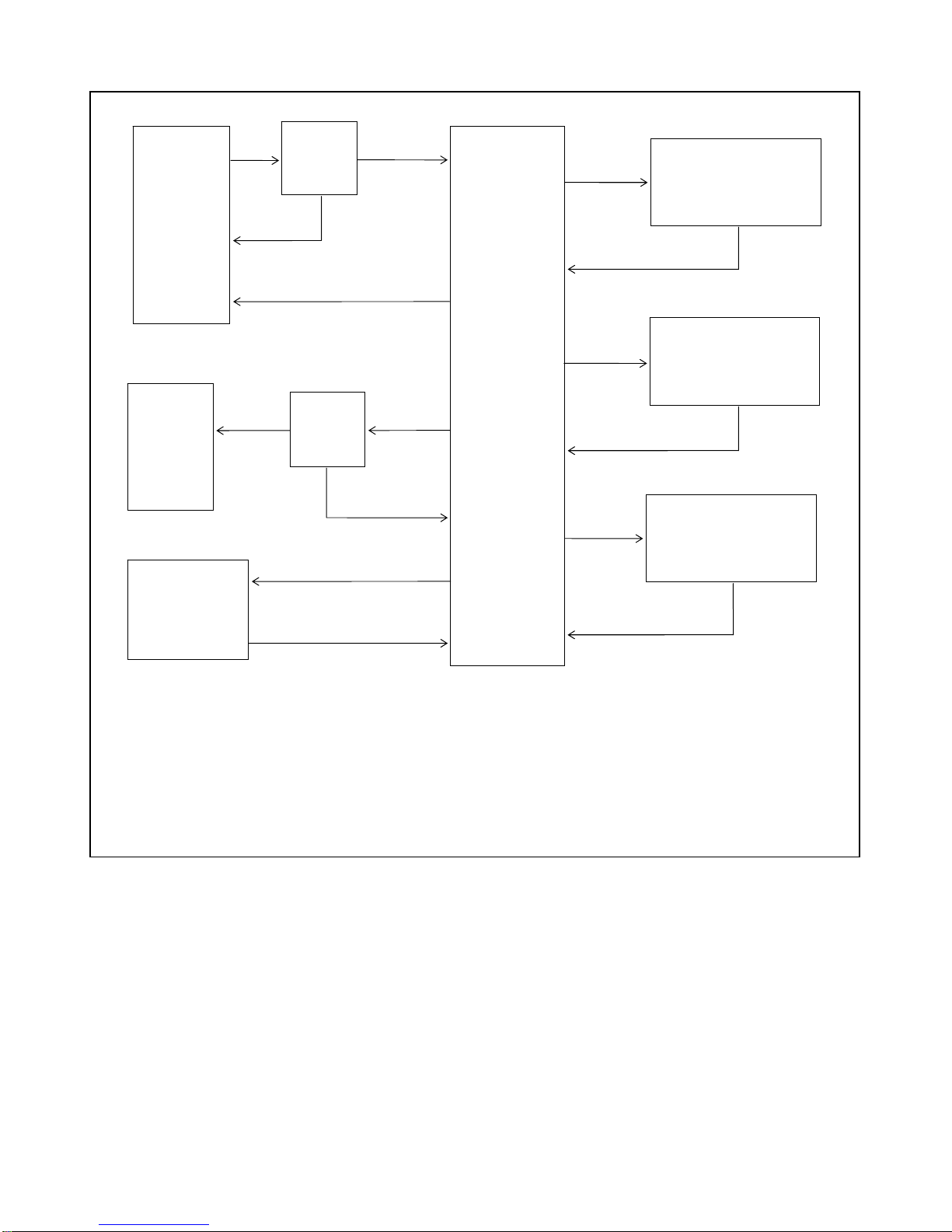
TERMINAL
EMULATION
PROGRAM
(1)
(3)
PASSWORD
PROMPT
(2)
PASSWORD
OK
PASSWORD
NO GOOD
USER
CONNECTED
TO
SELECTED
DEVICE
PORT
PASSWORD
OK
PASSWORD
PROMPT
(2)
PASSWORD
NO GOOD
PORT
NUMBER
OR
LABEL
“LOCAL>“
OR
“REMOTE”
PROMPT
LOCAL PORT
CONNECTED
TO MODEM
PORT
(4)
TIMEOUT OR DESELECT
[MODEM]
CODE
NOTES
1. “Dial” if using terminal regulator program for remote access; [ENTER] if accessing locally.
2. Password prompts will only appear if passwords have been enabled.
3. “Hang Up” if using terminal emulator program for remote access; [Q] if accessing locally.
4. [MODEM] command is only valid when accessing locally.
5. “[ ]” indicates a command entry using PC or terminal keyboard.
6. Entry descriptions or RFL 9660 responses appear in regular type.
Figure 4-28. Relationship between general access commands
[H]
DISPLAYED
[D]
COMPLETE
[I]
DISPLAYED
GENERAL ACCESS
COMMAND
LIST
(“HELP” SCREEN)
RUN DIAGNOSTIC
ROUTINE
PORT
INFORMATION
DISPLAY
RFL 9660 RFL Electronics Inc.
April 24, 2007 4-29 (973) 334-3100

Esc - ABORT COMMAND
If you start entering a user command and change your mind, press the [ESC] key instead of
the [ENTER] key to abort the command.
Format: REMOTE> ESC (no [ENTER])
For example, if you enter a "D" (Run diagnostics) and then press the [ESC] key, the following
message will appear on your display:
REMOTE> D -Command Cancelled-
Error
REMOTE>
You can also abort a command by pressing [CTRL][H] before pressing the [ENTER] key. This
will backspace over the command, erasing it.
H - DISPLAY COMMAND LIST
Whenever you are accessing the RFL 9660, you can view a list of the commands available to
you by using the "H" (help) command.
Format: REMOTE> H [ENTER]
The "H" command tells the RFL 9660 to send a list of all user commands to your terminal. A
typical command list appears in Figure 4-27. The system "super-user" can display a similar list,
but it has additional configuration commands on it. (See Section 5.)
D - RUN DIAGNOSTICS
Any time you want to make sure the RFL 9660 is working properly, you can use the "D"
command to run the RFL 9660's internal diagnostic program. For more information of the
diagnostic routine, refer to Section 10 of this manual.
I- PORT INFORMATION
The "I" command tells the RFL 9660 to generate the port information summary; this is a table
listing all available ports.
Format: REMOTE> I [ENTER]
A typical port summary table appears in Figure 4-29. The CPU automatically updates this table
as new ports (RS-232 or fiber) are added to the system.
RFL 9660 RFL Electronics Inc.
April 24, 2007 4-30 (973) 334-3100

(site ID)
# TYPE LABEL MODE DTR RTS CallBack
1 RS232 SEL 221F - Line 21 0 0 0 N
2 RS232 OPTIMHO - Line 15 0 0 0 N
3 RS232 DLP - Line 17 0 0 0 N
4 RS232 DFR 3 4 0 0 Y
5 RS232 QUANTUM 0 0 0 N
6 RS232 0 0 0 N
7 RS232 0 0 0 N
8 RS232 0 0 0 N
REMOTE> _
Figure 4-29. Typical port summary table
The following information appears in the port summary table:
# Port number (1 to 32). As more device port modules are added to the RFL 9660, more
lines will appear on this table, one for each installed port.
TYPE Type of connection ("RS232" for RS-232, or "FO" for fiber optic).
LABEL The name assigned to the port by the super-user. This is an optional field that may
contain up to 30 ASCII characters.
NOTE
Port labels are case-sensitive. If the port label was entered as all CAPITALS, you will have to enter
it that way for the RFL 9660 to accept it.
MODE Request connect method assigned to this port:
0 Port Callout not enabled.
1 RTS + DTR
2 DTR + RTS
3 RTS
4 DTR
9 Disabled by the switch. This means that a device timeout occurred and the RFL 9660
disabled the callout feature for that port. When this happens, the super-user will have
to use the "P" command to manually reset the port callout feature. (See Section 5.)
RFL 9660 RFL Electronics Inc.
April 24, 2007 4-31 (973) 334-3100

DTR This is an activity indicator; it will be "0" if DTR is not active, and "1" if it is active.
RTS This is an activity indicator; it will be "0" if RTS is not active, and "1" if it is active.
CallBack This is an enable indicator; it will be "Y" if callback is enabled, and "N" if it is not.
Q - QUIT SESSION
To disconnect your terminal from the RFL 9660 and end the session, use the "Q" command.
Format: REMOTE> Q [ENTER]
If you are using the Microsoft Windows Terminal Emulator, you can also disconnect your PC
from the RFL 9660 by clicking on "Phone" in the menu line, and then clicking on "Hang Up" in
the menu that appears. This will make your modem go on-hook.
Whichever method you use, the following message will appear on your display:
User terminates the session
The RFL 9660's STATUS display will read "hu," meaning that the RFL 9660 has begun its
hang-up sequence. When it is completed, the STATUS display will read "0" for a few seconds,
and then "PL." The RFL 9660 is then ready to start another session.
Port #/Label - PORT SELECTION
To connect your PC or terminal to one of the device ports on the back of the RFL 9660, enter
the port number or its label, and then press the [ENTER] key.
Format: REMOTE> port number or label [ENTER]
If you enter a number that is greater than the number of ports the RFL 9660 has, the following
error message will appear:
Cannot select port > than (maximum number of ports)
If you enter a number between one and the maximum number of ports the RFL 9660 has (8,
16, 24, or 32), the RFL 9660 will connect your terminal to that port.
If the super-user has enabled passwords, the following prompt will appear on your terminal:
Please enter password:
RFL 9660 RFL Electronics Inc.
April 24, 2007 4-32 (973) 334-3100

Enter the password on the keyboard, one letter at a time. For each letter of the password you
enter, the RFL 9660 will echo back an asterisk (*).
NOTE
Passwords are case-sensitive. If the super-user stored the password as all CAPITALS, you must
enter it that way. Otherwise, the RFL 9660 will reject it.
When you finish entering the password, press the [ENTER] key. If the RFL 9660 accepts the
password, your terminal will be connected to the device port. If it does not accept your
password, you will have to re-enter it.
Once your terminal is connected to the device port, the RFL 9660 is transparent to the
system and will only respond to the deselect code sequence ("BYE"). If this code interferes with
any of the application programs, notify the super-user. Only the super-user can change this
code. (See Section 5.)
4.8 DESELECTING A PORT
When you are finished using the device port, type in the deselect code, without pressing the [ENTER] key. (The
deselect code is usually "BYE," unless the super-user has stored another code in the RFL 9660's memory.)
Format: BYE (no [ENTER])
When the RFL 9660 receives the deselect code, it will disconnect you from the port (after a delay period that
can be changed by the super-user). Your normal prompt will appear again, and will be able to select another
port, or use any of the other general access commands. Also, other users will be able to use the device port you
were using.
If you forget to enter the deselect code and simply stop using your terminal, a timer inside the RFL 9660 starts
keeping track of the time. This timer is set at the factory for 10 minutes; it can only be reset by the super-user.
Once this timer times out, the RFL 9660 will disconnect your terminal from the device port. The RFL 9660 does
this to prevent one user from tying up a device and keeping other users from accessing it.
NOTE
The RFL 9660 will not respond if CTS/RTS or DTR/DSR flow control is involved and there is no device
connected to the selected port. You will have to wait for the timeout period to pass before the port will
be de-selected.
RFL 9660 RFL Electronics Inc.
April 24, 2007 4-33 (973) 334-3100

4.9 CONNECTING THE LOCAL AND MODEM PORTS
The "MODEM" command only appears if your PC is connected to the RFL 9660's front-panel LOCAL connector.
It allows you to connect the local port to the modem port for calling out to another substation. This also allows
you to change the factory-set configuration of the RFL 9660's modem (for example, the number of rings before
auto-answer).
To connect the local and modem ports, type in the word "MODEM," and then press the [ENTER] key.
Format: LOCAL> MODEM [ENTER]
The following prompt will appear on your display:
Local port connected to Modem port!
To alter type (deselect code)
When you are finished dialing out, type in the deselect code ("BYE"). The RFL 9660 will hang up and disconnect
the local port from the modem port. While it is doing this, the following message appears on your display:
Please wait...
When the RFL 9660 is ready for normal operation again, your normal prompt will reappear.
RFL 9660 RFL Electronics Inc.
April 24, 2007 4-34 (973) 334-3100

Section 5. CONFIGURATION COMMANDS
5.1 INTRODUCTION
In many installations, the person responsible for the RFL 9660 Digital Switch will want to control how the
RFL 9660 is configured and how users may gain access to it. This person (or some other authorized person)
would use the configuration commands in this section to control these functions. Since the people that normally
access the RFL 9660 are called "users," the person that uses the commands in this section is called the "superuser."
The configuration commands described in this section are only available to the system super-user. You may
wish to remove this section from the users' manuals. This would help prevent unauthorized modifications to the
system configuration.
NOTE
The super-user's password is always Password #3. If you do not enable password protection,
all users will be able to use the configuration commands described in this section. Since this is
not recommended, set up and enable passwords. (See Section 3.)
5.2 ACCESSING THE RFL 9660 AS A SUPER-USER
As a super-user, you can access the RFL 9660 either locally or remotely. To access it locally, follow the
instructions in Section 3 of this manual. To access it remotely with a PC and dial-up modem, refer to Section 4.
5.3 SUPER-USER COMMANDS
Besides the general access commands described in Section 4 of this manual, the RFL 9660 has configuration
commands that can only be used when you are logged on as a super-user. To view a list of these commands,
press the [H] and [ENTER] keys. This will tell the RFL 9660 to send a list of all super-user commands to your
terminal.
A typical super-user command list appears in Figure 5-1. This is similar to the user command list shown in
Figure 4-7, but it contains more commands. Figure 5-2 on shows the relationships between all super-user
commands.
For more information on each super-user command, refer to the page number listed below. Commands on the
super-user command list that are not listed below are described in Section 4 of this manual.
Command Meaning Page
H Help 5-2
P Program port 5-2
C Configure switch 5-12
S Save changes 5-21
R Reset port parameters 5-21
U Update hardware configuration 5-22
RFL 9660 RFL Electronics Inc.
August 18, 1998 5-1 (973) 334-3100

Esc -Abort command
H -Help
D -Run diagnostics
I -Port information
Q -Quit session
Port#/Label -Port selection
P -Program port
C -Configure switch
S -Save changes
R -Reset port parameters
U -Update hardware configuration
MODEM -Connect local port to modem port
LOCAL>_
Figure 5-1. Typical super-user command list display
H - HELP
The "H" command lets you view a list of all the commands you can use when you
are logged on as a super-user. These include the general access commands
described in Section 5, and the commands described in this section.
Format: LOCAL> H [ENTER]
This command tells the RFL 9660 to send a list of all super-user commands to your
terminal. A typical super-user command list appears in Figure 5-1. This is similar to
the general access command list described in Section 4, but it contains more
commands.
P - PROGRAM PORT
You can view detailed information about any of the RFL 9660's I/O ports by using
the "P" command.
Format: LOCAL> P [ENTER]
The RFL 9660 will return a prompt asking you for the port number.
Port #
If you enter a zero for the port number, the RFL 9660 will allow you to set the site
ID. The following prompt will appear:
Site ID
Old label was old label
Please enter new label, up to 30 characters. _
Type in the desired site ID, and press the [ENTER] key when you are finished. Your
regular prompt will return.
RFL 9660 RFL Electronics Inc.
August 18, 1998 5-2 (973) 334-3100

TERMINAL
EMULATION
PROGRAM
SAVE
CHANGES
RESET
PORT
PARAMETERS
USER
CONNECTED
TO
SELECTED
DEVICE
PORT
PASSWORD
(1)
(3)
OK
PASSWORD
PROMPT
(2)
PASSWORD
NO GOOD
CHANGES SAVED
PASSWORD
PROMPT
(2)
PASSWORD
OK
[S]
[R]
PORT RESET
PORT
NUMBER
LABEL
PASSWORD
NO GOOD
OR
“LOCAL>”
OR
“REMOTE>”
PROMPT
[H]
DISPLAYED
[D]
COMPLETE
[I]
DISPLAYED
[P]
[Q]
[C]
GENERAL ACCESS
COMMAND
LIST
(“HELP” SCREEN)
RUN DIAGNOSTIC
ROUTINE
PORT INFORMATION
DISPLAY
(ALL PORTS)
PORT CONFIGURATION
COMMAND LIST
(“PORT n>” PROMPT)
SWITCH CONFIGURATION
COMMAND LIST
(“CONFIG>” PROMPT)
LOCAL PORT
CONNECTED
TO MODEM
PORT
(4)
[MODEM]
TIMEOUT OR
DESELECT CODE
[Q]
[U]
ADDRESSES LEARNED
UPDATE HARDWARE
CONFIGURATION
(LEARN FIBER OPTIC
ADDRESSES IF CHANGED)
NOTES:
1. “Dial” if using terminal emulator
2. Password prompts will only appear if passwords have been enabled.
3. “Hang Up” if using terminal emulator program for remote acdess; [Q] if accessing locally.
4. [MODEM] command is only valid when accessing locally.
5.”[ ]” indicates a command entry using PC or terminal keyboard.
6. Entry descriptions or RFL 9660 responses appear in regular type.
program for remote access; [ENTER] if accessing locally.
Figure 5-2. Relationships between super-user commands
RFL 9660 RFL Electronics Inc.
August 18, 1998 5-3 (973) 334-3100
 Loading...