


RFL Communications plc
U
U
U
t
t
t
i
i
i
l
l
l
i
i
i
t
t
t
y
y
y
N
N
N
e
e
e
t
t
t
w
w
w
o
o
o
r
r
r
k
k
k
S
S
S
p
p
p
e
e
e
c
c
c
i
i
i
a
a
a
l
l
l
i
i
i
s
s
s
t
t
t
s
s
s
SMX3 / 21 Sub-MUX
X.21 / V.24 Dual-Protocol sub-rate multiplexer
User Manual
Issue 1.4
RFL SMX3 / 21 Page 2 of 22 Issue 1.4
User Manual
08 June 2009
Contents
1. Introduction............................................................................................................ 3
2. Features................................................................................................................ 3
3. Concatenation and Network Timing...................................................................... 4
4. Equipment Layout ................................................................................................. 4
5. Channel Characteristics........................................................................................ 5
6. X.21 Aggregate Port .............................................................................................. 6
7. Concatenation Port................................................................................................ 8
8. X.21 Data Port (Channel A)................................................................................. 10
9. V.24 Data Ports (Channels B & C)......................................................................11
10. DIP Switches.......................................................................................................13
11. LEDs.................................................................................................................... 18
12. Power Input......................................................................................................... 19
13. Alarms................................................................................................................. 19
14. Example Configurations...................................................................................... 20
15. Blank Setting Table............................................................................................. 22
Issue Comments Date
1.0 Draft issue 19 February 2009
1.2 Initial Release
Applicable Firmware release smx-2-1-0-1.mcs
04 March 2009
1.3 Example configurations added, timing details expanded 07 May 2009
1.4 Loopback schematics added 08 June 2009
RFL SMX3 / 21 Page 3 of 22 Issue 1.4
User Manual
08 June 2009
1. Introduction
Prompted by SP Powersystems’ operational requirements in the former MANWEB
region, RFL developed a four channel sub-multiplexer to support operation of their
MPR – LZPK102 protection relays and SCADA systems over leased digital circuits.
The requirements for this multiplexer is described in SMX3/40 Sub-MUX X.21 High
speed sub-rate multiplexer User Manual Release 2.01.
This new Dual-Protocol version, SMX3/21, is designed to support protection relays
with an X.21 serial interface rather than a V.24 interface, together with two V.24
channels (typically used for RS232) that can be used for the existing SCADA
equipment.
2. Features
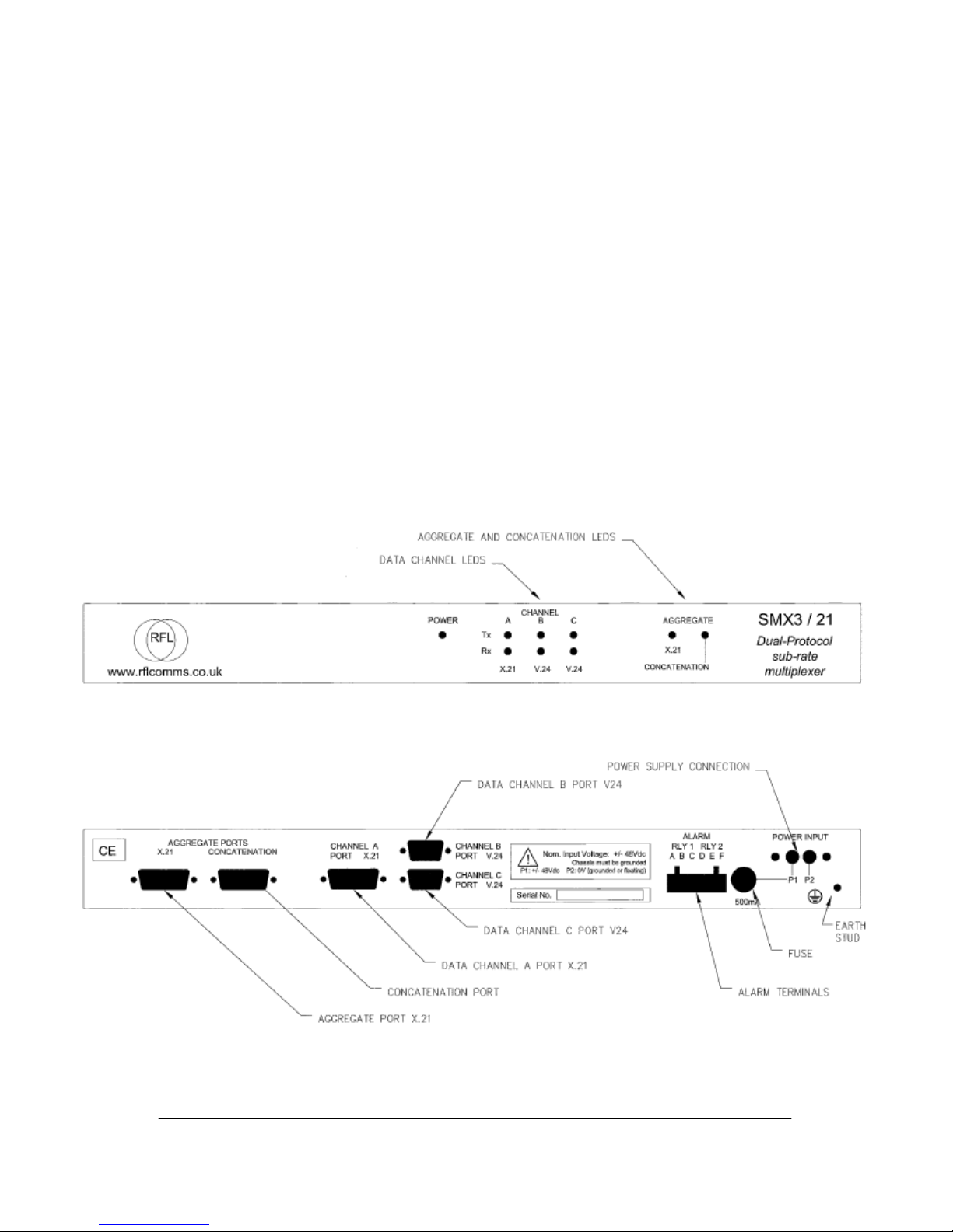
The RFL SMX3/21 Sub-MUX is a hardened (EATS 48-5) sub-rate multiplexer. The
equipment is 19” rack mountable, 1U high, with reversible mounting brackets
permitting either the connectors or the LEDs to face the front of the rack.
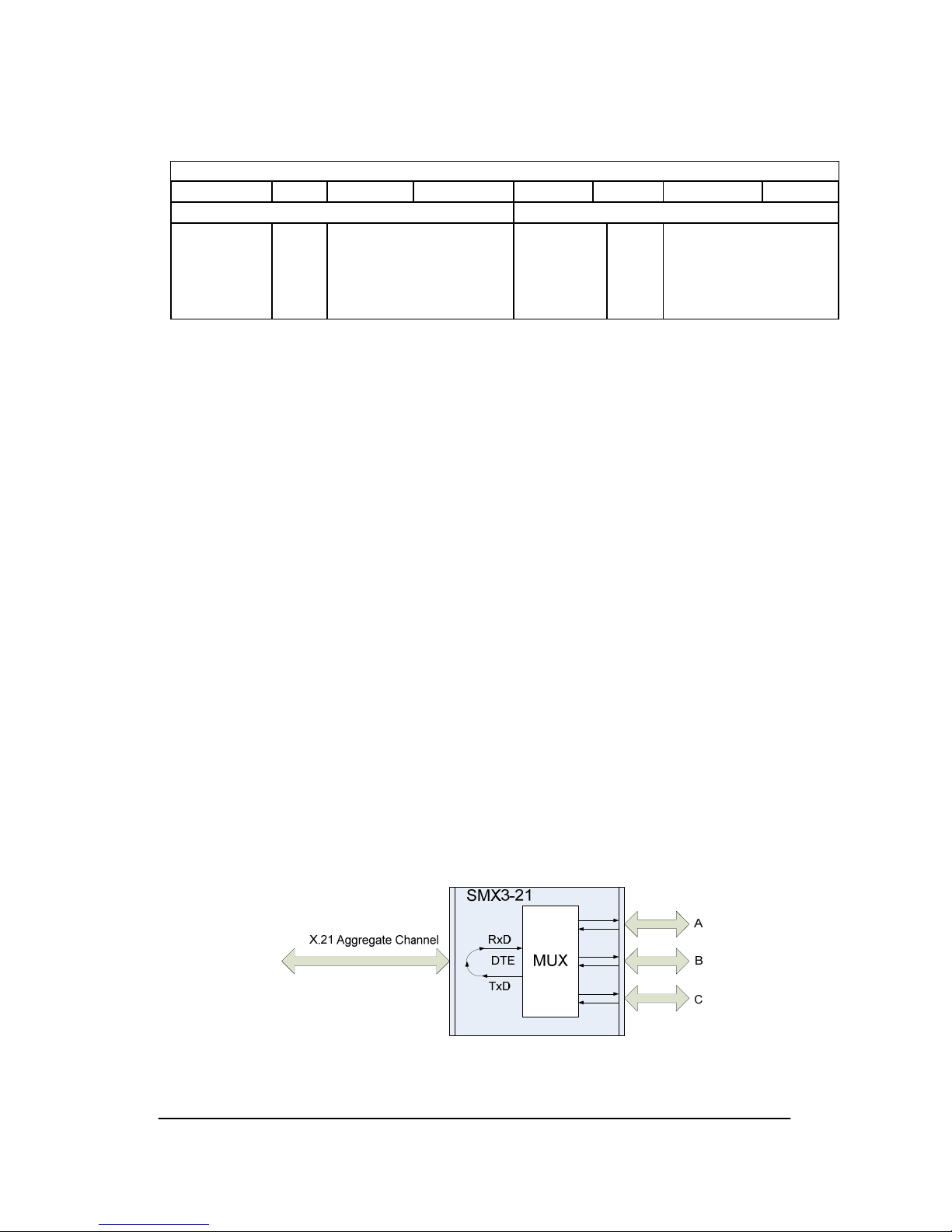
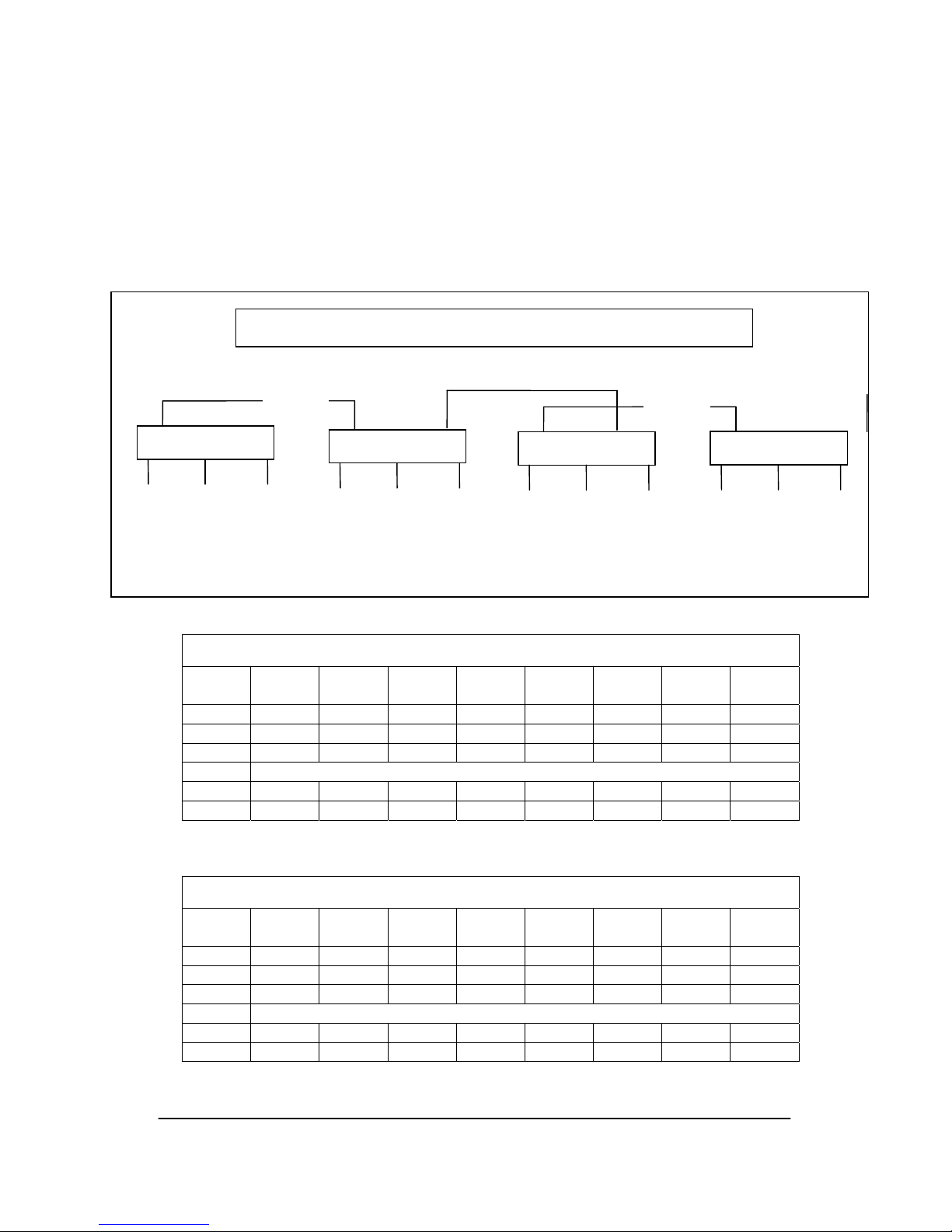
SMX3/21 aggregates one X.21 data channel (Channel A) and two V.24 data
channels (Channel B & Channel C) across a single point to point X.21 service. Data
Channel A is permanently allocated to Aggregate Channel 1. The V.24 Data
Channels B and C may both be assigned to either Aggregate Channel 2 or
Aggregate Channel 3. Both V.24 channels may be assigned to a single aggregate
channel; this feature is useful for supporting SCADA systems where multiple
terminals are attached.
LEDs are provided for Power Supply healthy and for the status of all ports. Two volt
free alarm changeover contacts are provided for Power and Aggregate
Communications healthy.
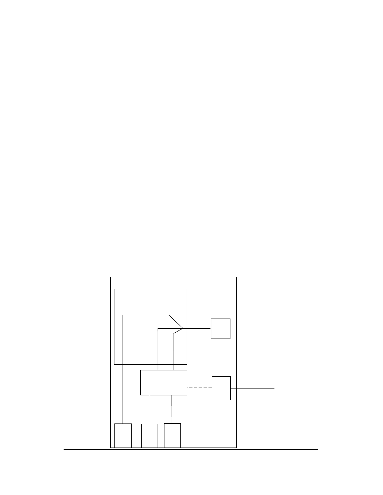
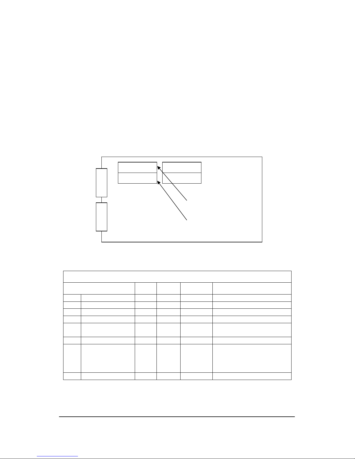
BT KiloStream or similar
Port
assignment
& sharing
X.21
Port
V24
Channel B
Optional Aggregate Concatenation
SMX3 / 21
Block Diagram
Ch. A
Port
X.21
Concat.
Port
X.21 Channel A
Ch. B
Port
V24
Ch. C
Port
V24
V24
Channel C
MUX
Agg.Channel 1
A
gg.Channel 2
A
gg.Channel 3
RFL SMX3 / 21 Page 4 of 22 Issue 1.4
User Manual
08 June 2009
3. Concatenation and Network Timing
SMX3/21 will operate on a network of concatenated X.21 links. A facility is provided
so that two co-located SMX3/21 (i.e. one at each end of separate X.21 links) units
can be linked ‘back to back’. This feature is referred to as Aggregate Concatenation.
In this case the units may be configured so that the data on Channel A and / or
Channel B is re-transmitted onto a second point to point link at the aggregate level
via the Concatenation Port. For this to operate all links must be synchronised to the
network master timing signal. If any link within the network is unsynchronised (e.g. a
single radio link), SMX3/21 provides the option to output master network clock
signals to otherwise unsynchronised links.
An alternative option is to concatenate a single data channel at V.24 level by daisychaining the V.24 data links. This is referred to as Data Channel Concatenation. In
this case each X.21 link may be free-running (unsynchronised).
4. Equipment Layout
RFL SMX3 / 21 Page 5 of 22 Issue 1.4
User Manual
08 June 2009
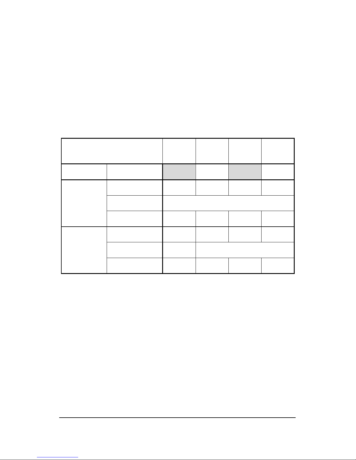
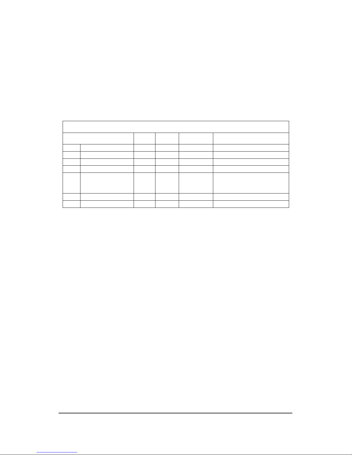
5. Channel Characteristics
The maximum bandwidth that may be configured for Data Channel A (X.21) is a
function of the speed of the aggregate.
The sample rates for Aggregate Channels 2 & 3 are also a function of the aggregate
speed; thus the maximum baud rate that can be configured for Data Channels B & C
are a function of both the aggregate speed and the aggregate channel to which they
are assigned. The range of baud rate settings remains the same regardless of
aggregate speed.
Data Channel Aggregate Speed 64kbit/s 128kbit/s 192kbit/s 256kbit/s
Channel A
(X.21)
Bandwidth kbit/s
64
64 or 128
Sample Rate 16k 32k 48k 64k
Baud Rate range
(Async Mode)
1200 - 9600
Channel B or C
(V.24) assigned
to Agg. Ch 2
Baud Rate range
(Transparent Mode)
4800 9600 19200 38400
Sample Rate 8k 16k 24k 32k
Baud Rate range
(Async Mode)
1200 -
4800
1200 - 9600
Channel B or C
(V.24) assigned
to Agg. Ch 3
Baud Rate range
(Transparent Mode)
2400 4800 9600 19200
Transparent Mode is a high speed configuration for the V.24 ports particularly suited
to applications for protection relays. The end to end delay in this mode is less than
0.5s (excluding delays introduced by the comms link).
RFL SMX3 / 21 Page 6 of 22 Issue 1.4
User Manual
08 June 2009
6. X.21 Aggregate Port
The X.21 port is a DB15 male connector; this is connected internally to a header on
the PCB using a ribbon cable. The X.21 port may be configured as DTE or DCE by
fitting the ribbon cable to the appropriate X.21 Port Header, and by selecting settings
on DIP switch 5. Note: DTE is the standard configuration, and is used in all
applications where the network provides the signal timing.
Transceivers are specified to ± 15kV IEC1000-4-2 air discharge ESD protection and
port connections are additionally protected by Tranzorb type arrays.
This port carries an aggregate of three bi-directional data channels; one X.21
channel and two V.24 channels.
Standard X.21 Port Pin-out (when in DTE configuration) – D15M on chassis
Circuit Pin A Pin B Direction Notes
T Transmit Data 2 9 Output
R Receive Data 4 11 Input
C Control 3 10 Output Permanently on
I Indication 5 12 Input Signal ignored
S
Signal Element
Timing
6 13 Input Timing signal derived from
the network
G Ground 8 15
X Signal Element
Timing
7 14 Output Timing signal transmitted to
network (X). Special applications
only. Requires to be enabled
using mode DTE + Timing X
enabled
Screen / Drain
Must be earthed to shell
X.21 (DTE)
X.21 (DCE)
X.21 V24
X.21 header locations
Headers connected
to X.21 Port
Standard header location
DCE header location only
used when SMX3/40
provides signal timing
RFL SMX3 / 21 Page 7 of 22 Issue 1.4
User Manual
08 June 2009
The DCE configuration may be used in specific circumstances where signal timing
from the network timing is unavailable (e.g. when used with a radio link that does not
provide a clock source). Two alternatives are:
The timing source is derived from a co-located unit that is itself deriving the
master clock signal from the network. The two units are interconnected via the
concatenation link (refer to following section. In this case Clock Source must be
configured to Concat Port.
The timing source is derived from within the unit; in this case the Clock
Source must be configured to Master.
In both cases the timing signal is output on pins 6 and 13.
Optional X.21 Port Pin-out (when in DCE configuration) – D15M on chassis
Circuit Pin A Pin B Direction Notes
T Transmit Data 2 9 Input
R Receive Data 4 11 Output
C Control 3 10 Input Signal ignored
I Indication 5 12 Output Permanently on
S Signal Element
Timing
6 13 Output Timing signal derived from
the port and transmitted to
network
G Ground 8 15
Screen / Drain
Must be earthed to shell
In either configuration, use 6 pair plus ground stranded cable with overall shield
(eg RS 111-8994).
Maximum recommended length in substations - 10m (Check Utility standards).
DIP switches provide configuration options, see section 10.

RFL SMX3 / 21 Page 8 of 22 Issue 1.4
User Manual
08 June 2009
7. Concatenation Port
The Concatenation Port provides optional direct connection to a co-located SMX3/21
that is serving another X.21 link. Unless interrupted by a particular V.24 port setting,
aggregate channel data passes between this port and the X.21 port. This port has
the same capacity as the X.21 Port. Signal timing is always transferred across the
Concatenation port when the port mode is set to ‘Enabled as Concatenation’.
The Concatenation Port is a DB15 female connector; this is connected internally to a
header on the PCB using a ribbon cable. The Concatenation Port may be configured
as DTE or DCE by fitting the ribbon cable to the appropriate X.21 Port Header, and
by selecting settings on DIP switch 5. Note: DTE is the standard header location
used for Aggregate Concatenation i.e. direct connection to a co-located
SMX3/21.
Transceivers are specified to ± 15kV IEC1000-4-2 air discharge ESD protection and
port connections are additionally protected by Tranzorb type arrays.
Aggregate Concatenation
Aggregate Concatenation is the interconnection at aggregate level of two co-located
SMX3/21 units. For this function the Concatenation Port is configured as Enabled as
Concatenation mode, (i.e. DTE with Timing X enabled). The timing signal is derived
from the port and is transmitted on pins 7 and 14 (Xa and Xb).
In installations where the X.21 aggregate that is connected to each co-located unit
receives timing from the network master clock, the clock source for both units should
be configured as X.21 Port.
In installations where the X.21 aggregate that is connected to one or both co-located
units do not receive timing from the network, the source of the timing signal must be
determined and the clock source for each unit should be configured as X.21 Port,
Concat Port or Master as appropriate (refer to DIP Switch 6 settings).
DIP switches provide configuration options, see section 10.
CONC. (DCE)
CONC. (DTE)
X.21 V24
Headers connected
to X.21 Port
Headers connected
to Concatenation
Concatenation header locations
Header location used for
Aggregate Concatenation

RFL SMX3 / 21 Page 9 of 22 Issue 1.4
User Manual
08 June 2009
Standard Concatenation Port Pin-out (DTE configuration)
as used for Aggregate Concatenation - D15F on chassis
Circuit Pin A Pin B Direction Notes
T Transmit Data 2 9 Output
R Receive Data 4 11 Input
S Signal Element
Timing
6 13 Input Timing signal derived from the
network
G Ground 8 15
X Signal Element
Timing
7 14 Output Timing signal derived from the
port and transmitted to network.
C Control 3 10 Output Permanently on. Not used in
Aggregate Concatenation
I Indication 5 12 Input Signal ignored. Not used in
Aggregate Concatenation
Screen / Drain
Must be earthed to shell
Aggregate Concatenation to a co-located SMX3/21 requires a five twisted pair crossover cable with overall shield (eg RS 111-8988). Maximum recommended length
10m (check Utility standards).
Aggregate Concatenation Cable
D15M – D15M
Pair Pin End 1 End 2
A 2 4
1
B 9 11
A 4 2
2
B 11 9
A 6 7
3
B 13 14
A 7 6
4
B 14 13
A 8 8
5
B 15 15
Screen / Drain
Must be earthed to
connector shells at
both ends
The following table is for information only, and is not used in any standard configurations.
Optional Concatenation Port Pin-out (when in DCE configuration) – D15F on chassis
Circuit Pin A Pin B Direction Notes
T Transmit Data 2 9 Input
R Receive Data 4 11 Output
C Control 3 10 Input Signal ignored
I Indication 5 12 Output Permanently on
S Signal Element
Timing
6 13 Output Timing signal derived from
the port and transmitted to
network
G Ground 8 15
Screen / Drain
Must be earthed to shell

RFL SMX3 / 21 Page 10 of 22 Issue 1.4
User Manual
08 June 2009
8. X.21 Data Port (Channel A)
The port for Channel A is a DB15 female connector; it is configured as DCE.
Channel A Port Pin-out – D15F on chassis (DCE)
Circuit Pin A Pin B Direction Notes
T Transmit Data 2 9 Input
R Receive Data 4 11 Output
C Control 3 10 Input see Note below
I Indication 5 12 Output See Note below
S Signal Element
Timing
6 13 Output Timing signal transmitted
to network
G Ground 8 15
Screen / Drain
Must be earthed to shell
Transceivers are specified to ± 15kV IEC1000-4-2 air discharge ESD protection and
port connections are additionally protected by Tranzorb type arrays.
Data received at the Channel A port is always terminated; it cannot be concatenated
across the concatenation link.
S is normally synchronised to network timing but in the event of this being
unavailable runs from an internal source within the SMX.
Note:
When DIP SW 1-2 is set to Local, I is ON when the channel is legally configured, the
aggregate is running and in sync, in which case C is ignored
When DIP SW 1-2 is set to Remote, I is ON when the channel is legally configured,
the aggregate is running and in sync, and C is received from the remote end.
RFL SMX3 / 21 Page 11 of 22 Issue 1.4
User Manual
08 June 2009
9. V.24 Data Ports (Channels B & C)
Ports B and C are DCE ports on DB9 female connectors for asynchronous data:
Channels B & C Ports Pin-out – D9F on chassis (DCE)
Circuit Pin Direction
TxD Transmit Data 3 Input
RxD Receive Data 2 Output
RTS Request to Send 7 Input
CTS Clear to Send 8 Output
DCD Data Carrier Detect 1 Output
DTR Data Terminal Ready 4 Input
DSR Data Set Ready 6 Output
RI Ring Indicator 9 Output
SG Signal Ground 5
Screen / Drain must be connected to the connector Shell
RI is permanently OFF.
DSR is ON when aggregate framing is synchronised.
DTR is ignored.
RTS turns on remote DCD and local CTS after a delay.
Transceivers are specified to ± 15kV IEC1000-4-2 air discharge ESD protection and
port connections are additionally protected by Tranzorb type arrays.
DIP switches provide configure options for each port, see section 10.
V.24 Port Sharing
There are two methods by which multiple V.24 ports can be assigned to an
aggregate channel:
Channels (ports) B and C within an SMX3/21 unit are assignable to
Aggregate Channels 2 and / or 3.
Where two SMX3s are co-located and interconnected via the concatenation
ports, it is possible for each of Channels B & C to be selected to communicate
over either via X.21 aggregate channel or the concatenation port in which
cases the channel terminates within the SMX3/21, via both ports, for daisychain applications via a co-located SMX3/21.
Where multiple V.24 ports are assigned to a channel (on one or multiple
SMX3/21 units), data from the channel is presented at RxD of all ports other
than the source of the data, and data to the channel is an ‘or’ function of TxD
of those ports where RTS is asserted ON. It is important therefore that
equipment connected in this way, such as a SCADA system, has the selfdiscipline for only one to be transmitting at any time.

RFL SMX3 / 21 Page 12 of 22 Issue 1.4
User Manual
08 June 2009
V.24 Data Channel Concatenation
SMX3/21 units co-located at one end of adjacent unsynchronised links may be
concatenated at the V.24 level either through the connected equipment, or directly
using a crossed RS232 data cable.
V.24 Port Performance
V.24 circuits operate to emulate a modem:
CTS follows the state of local RTS after any necessary delay, when the
Aggregate is working and in synchronism.
DCD follows the state of remote RTS when the Aggregate is working and in
synchronism.
DTR is ignored and can be left unconnected, the sub-multiplexer assumes a
continuous ON state.
DSR is ON when the Aggregate is working an in synchronism.
RI is unconnected or permanently OFF.
When RTS turns ON, CTS turns ON when it can be assured that data presented at
TxD will reach RxD at a remote end after DCD there has turned ON. This does not
exceed 10 ms.
It is possible to configure each port to limit the duration of the effect of RTS to protect
a SCADA system from an RTU which fails to turn RTS off after it has sent a
response. When enabled, by DIP switch (SW 6-1 and 6-2), if RTS remains ON for
longer than 2 seconds, its effect is terminated and its ON condition is not recognised
again until it has been OFF for longer than 2 seconds.

RFL SMX3 / 21 Page 13 of 22 Issue 1.4
User Manual
08 June 2009
OFF
1 - ON
SW 1
SW 2
SW 3
SW 4
SW 5
SW 6
Pos’n 1
Pos’n 8
X.21 V24
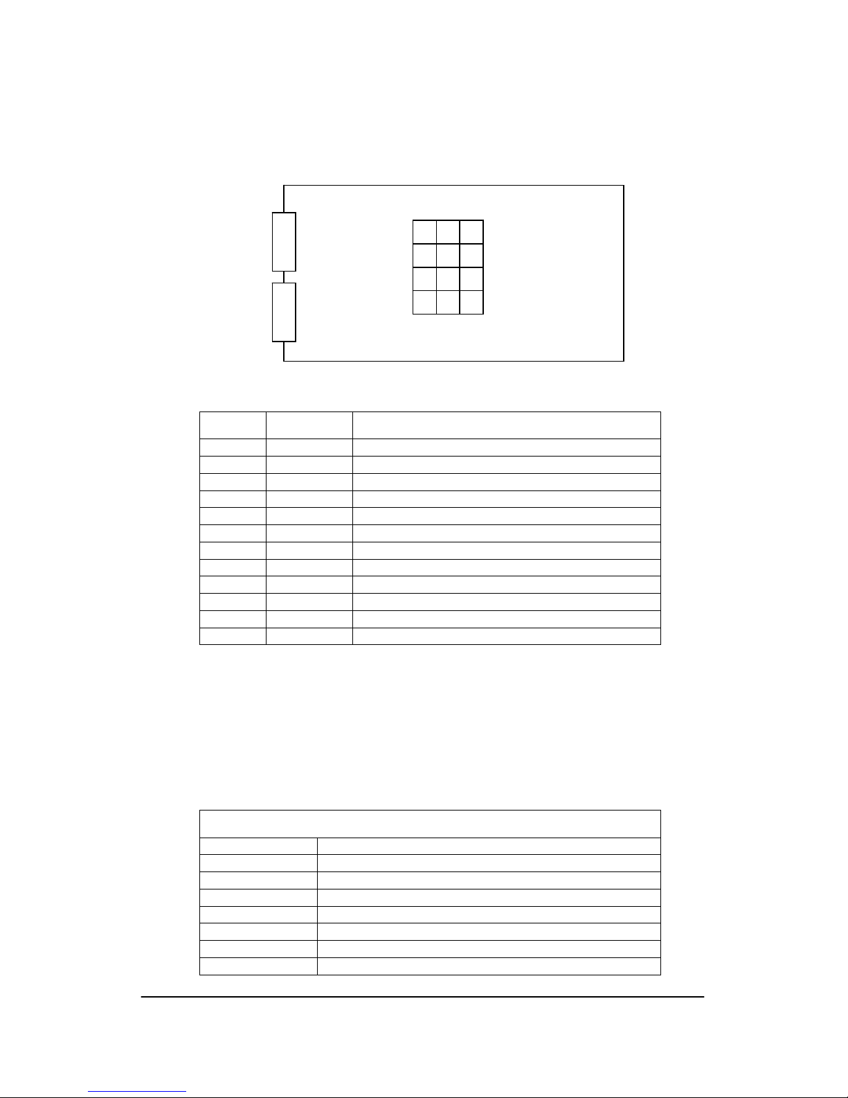
10. DIP Switches
DIP Switch Locations
Dip Switch functions
SW1 SW2 SW3 SW4 SW5 SW6
Channel A
X.21 Data
configuration
Channel B
V.24 Data
configuration
Channel C
V.24 Data
configuration
Not used
Aggregate &
Concatenation
enabling
Clock and
Timing
configuration
Setting data is in the following tables.
Refer to Section 14 for example configurations.
1 = ON

RFL SMX3 / 21 Page 14 of 22 Issue 1.4
User Manual
08 June 2009
DIP Switch 1 settings:
SW 1 X.21 Data Channel A Configuration
8 7 6 5 4 3 2 1
Bandwidth
Not
Used
Always
set to 0
Not
Used
Local Loop Indicate Port Enable
00 = 64K 0= Off 0= Local 0= Off
01 = 128K
1= On
(Test only)
1= Remote 1= Enabled
10 = Not Used (See Note
11 = Not Used Section 8)
• Bandwidth
Set to 64kbit/s, or 128kbit/s if permitted by the speed of the aggregate (refer to table in
section 5).
•
Local Loop Off / On.
Normally set to Off
When set to On, data transmitted into of the MUX TxD is looped back to its RxD output.
Channel A requires the clock to be present; as this is a DCE port the clock is sourced
from the MUX; provided this is present local loop operation is always possible.
• Indicate
When set to Local, I is ON when the channel is legally configured, the aggregate is
running and in sync, in which case C is ignored
When set to Remote, I is ON when the channel is legally configured, the aggregate is
running and in sync, and C is received from the remote end
.
• Channel Enable.
Set to On to enable Channel A X.21 Data Channel
c
X.21 Aggregate Channel
SMX3-21
A
C
B
TxD
RxD
DCE
MUX
Data Channels
RFL SMX3 / 21 Page 15 of 22 Issue 1.4
User Manual
08 June 2009
DIP Switch 2 – 3 settings:
SW 2 V.24 Data Channel B Configuration SW3 – V.24 Channel C Configuration
8 7 6 5 4 3 2 1
Baud Rate Route Mode
Agg Channel
Assignment
00 = 1200 00 = via X.21 Agg. Port 00 = Disabled 00 = Ch 2
01 = 2400 01 = via Concat. Port 01 = Transparent 01 = Ch 3
10 = 4800 10 = Both Ports 10 = Async 8 bit
11 = 9600 11 = Local Loop 11 = Async 9 bit
• Channel Allocation and Sharing: Select aggregate channel 2 or 3
Each V.24 Data Channel can be allocated to Aggregate Channel 2 or 3. More than
one port may share a channel.
Where more than one Data Channel is allocated to the same Aggregate Channel, the
ports share the aggregate channel. From the point of view of one of those ports,
Transmit Data would be sent over the aggregate channel and to all other ports
allocated to the same channel. Data from the aggregate channel or other such port(s)
would appear as Received Data. This feature is useful for supporting SCADA
systems where multiple terminals are attached, but they must be well disciplined
where only one terminal transmits at once, waiting for CTS after asserting RTS.
• Mode: Disabled, Transparent, Async 8 bit, Async 9 bit.
Transparent is used where end-to-end delay is critical and may also be used for
applications where asynchronous character formats are not specifically supported.
The baud rate settings are ignored. (See section 5)
Async 8 bit is selected for: 7 data bits plus 1 parity bit (even or odd).
or: 8 data bits plus 0 parity bit.
Async 9 bit is selected for: 8 data bits plus 1 parity bit (even or odd).
• Route: X.21 Port, Concatenation Port, Both Ports.
If X.21 Port is selected, traffic on the allocated aggregate channel terminates at this
port. That channel is then available for other traffic over the Concatenation Port.
If Concatenation Port is selected, data on the selected aggregate channel terminates
at this port and that channel is available for other data over the aggregate.
If Both is selected, traffic on the selected aggregate channel between X.21 Port and
Concatenation Port appears at RxD as an 'or' of data from either direction, and TxD is
sent in both directions. This mode is suitable only for a well-disciplined system
(where only one terminal transmits at once), waiting for CTS after asserting RTS.
Local Loop operates as described for DIP Switch 1
As channels B and C are asynchronous there is no requirement for a network clock.
• Baud Rate: 1200, 2400, 4800, 9600 bits/sec.
When Async 8 or Async 9 mode is selected, set the baud rate to match the
connected equipment. 9600 bits/s requires allocation to a 32kHz sampling channel.
Do not set different baud rates for ports allocated to the same aggregate channel.
RFL SMX3 / 21 Page 16 of 22 Issue 1.4
User Manual
08 June 2009
DIP Switch 5 settings:
Switch 5 – X.21 Aggregate Channel and Concatenation Channel Enabling
8 7 6 5 4 3 2 1
Concatenation Port X.21 Port
Local Loop Spare Mode Local Loop Spare Mode
0 = Off
00 = Disabled
0 = Off
00 = Disabled
1 = On
01 = Enabled as DTE
1 = On
01 = Enabled as DTE
(Test only)
10 = Enabled as DCE
(Test only)
10 = Enabled as DCE
11 = Enabled as Concat
11 = Not used
• Mode: Disabled, Enabled as DTE, Enabled as DCE, Enabled as Concat (ie
DTE + Timing Signal X)
Enabled as DTE. This is the normal setting for the X.21 Port when connecting to X.21
links carrying network master clock timing (eg BT Kilostream)
Enabled as DCE. This optional setting is used when the X.21 link requires to be
synchronised to the network master clock signal received from a co-located
SMX3/21, (or to itself as master where network timing is unavailable). The timing
signal X is output on pins 6 and 13 (Sa and Sb). Timing must be selected
Enabled as Concat (ie DTE + Timing X). This is the normal setting for the
Concatenation Port when connecting to a co-located SMX3/21 using the Aggregate
Concatenation facility. The timing signal X is output on pins 7 and 14 (Xa and Xb).
• Local Loop: Off / On
Normally set to Off.
When set to On, data transmitted out of the MUX on the aggregate is looped back to
its Receive input. The clock is required for this to function.
The method of operation is the same for the X.21 Aggregate Port and for the
Concatenation Port.
- In DTE mode (normal operation) the clock is sourced from the network, so
the network connection must be present for the local loop to operate.
- In DCE mode the clock is sourced from the MUX so the local loop works
independently of the network connection.
- In Concatenation mode the clock is sourced from the unit at the opposite
end of the link, so an SMX3/21 must be present at each end of the
concatenation link.
RFL SMX3 / 21 Page 17 of 22 Issue 1.4
User Manual
08 June 2009
DIP Switch 6 settings:
Switch 6 – Clock and Timing Configuration
8 7 6 5 4 3 2 1
RTS Time Out
Aggregate Speed
kbit/s
Clock
Source
Not Used
Port C Port B
00 = 64 00 = X.21 Port 0 = Disabled 0 = Disabled
01 = 128 01 = Concat port 1 = Enabled 1 = Enabled
10 = 192 10 = Master
11 = 256 11 = Auto
• V.24 Port RTS Timeout:
Normally set to Enabled for a polling system.
When Enabled, the effect of RTS ON is limited to 2 seconds, i.e. CTS and remote
DCD turn OFF and TxD is blocked. In order to recover, RTS presented to the
port has to turn off and remain off for 2 seconds. This feature is to prevent a faulty
RTU of a SCADA system from interfering with traffic on the rest of the SCADA
system.
Do not set to Enabled when port is dedicated for use with MPR or other protection
relay, or when testing with a data tester.
• Timing source: X.21 Port, Concatenation Port, Master, Auto,
X.21 is the normal setting for applications where the SMX3/21 X.21 port is connected
to a service synchronised with the network master clock.
Concatenation Port is the setting used when an X.21 link needs to be synchronised to
the network master clock signal from an adjacent link. Signal timing is via the
concatenation port from the co-located unit. When used in conjunction with the
modes Enabled as DCE, (or Enabled as DTE + Signal Timing X), the timing signal
received from the concatenation port will be output onto the X.21port.
Master is used where it is necessary for timing to be generated internally for SMX/21.
The clock is generated internally and transmitted on X on either the X.21 Aggregate
port or the Concatenation port. It is used with Enabled as DCE mode, (generally for
test purposes only), and for Enabled as Concat mode where two units are
interconnected via concatenation ports and the X.21 network service is unavailable.
Auto locks timing to the X.21 port as a priority and to the Concatenation port if that
fails. When timing is locked to the Concatenation port and an acceptable clock
appears on the X.21 port, timing source will revert to the X.21 port. This function has
a special application for East-West applications where both X.21 and Concatenation
ports receive network master clock timing.
This is not used when concatenating
consecutive point to point links using the concatenation port to connect to an colocated SMX3/21.
• Aggregate Speed: 64, 126, 192, 256 kbits/s
Set to match the network clock speed. For X.21 networks operating at n = 1, set to
64kbits/s. (Note: when using Channel A (X.21 port), it is not possible to use 64 or
192kbits/s, but it is possible to use the V.24 ports alone)
RFL SMX3 / 21 Page 18 of 22 Issue 1.4
User Manual
08 June 2009
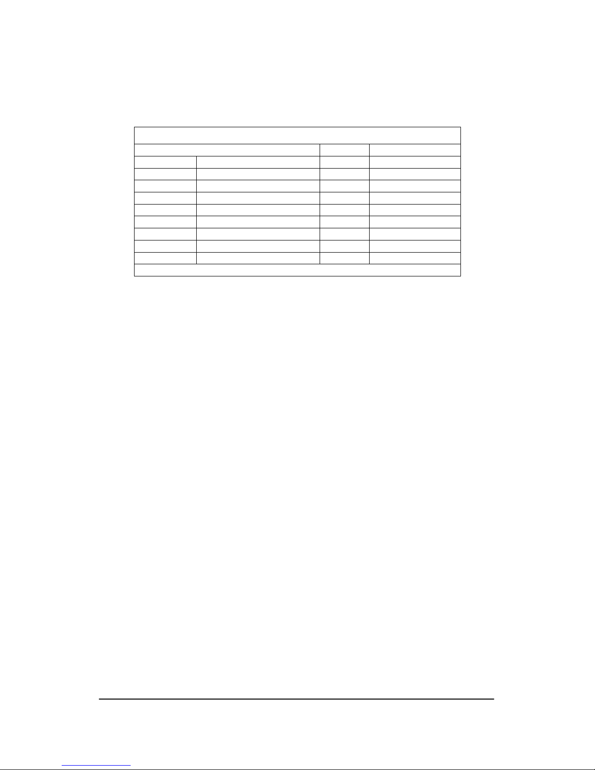
11. LEDs
12 LEDs are located in the centre of the board for connection via flexible light pipes
to display locations. See equipment layout.
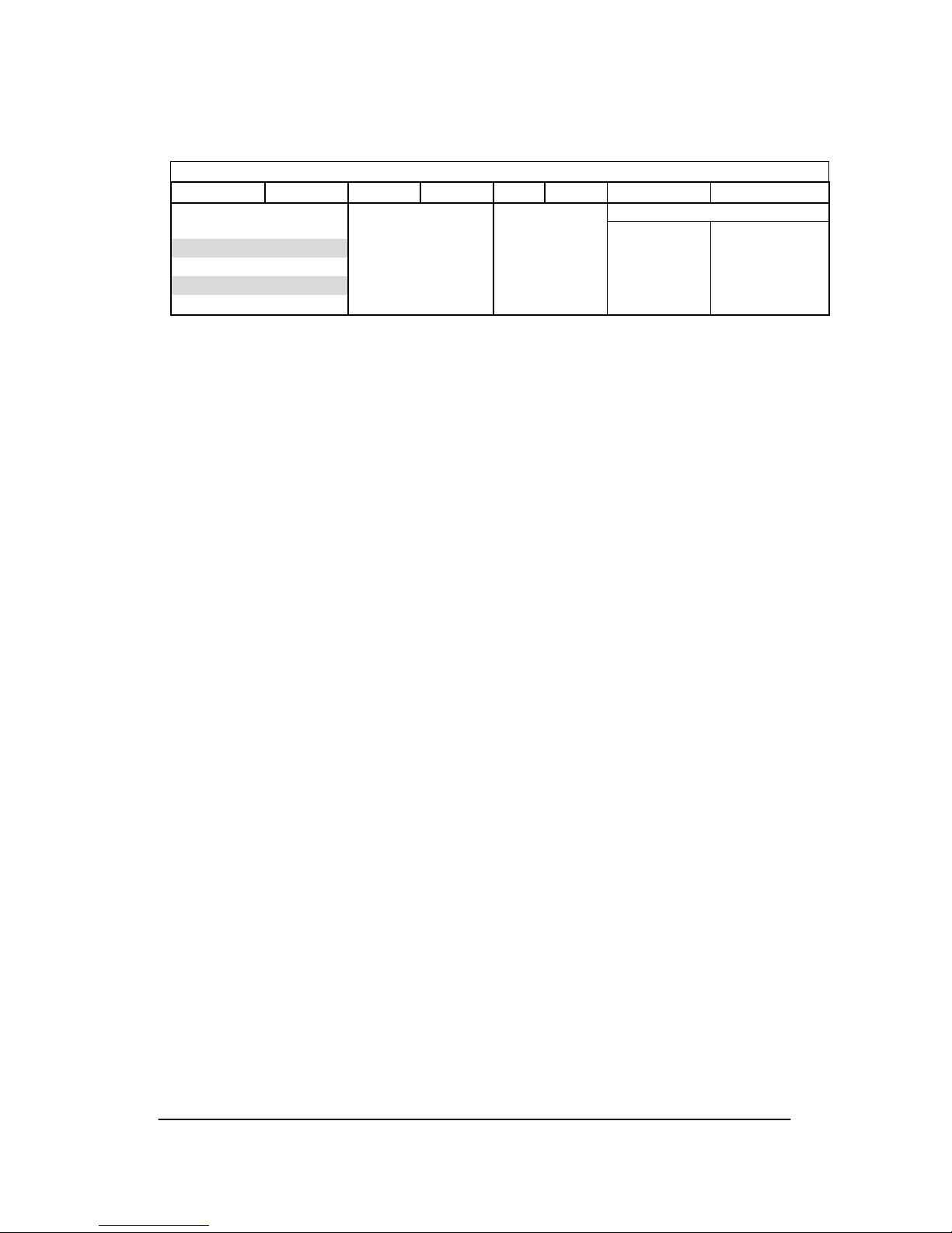
LED Colour Function
1 Green Power input 1
2 Green Power input 2 (only where applicable)
3 Green X.21 Data Port A Transmitting data
4 Green X.21 Data Port A Receiving data
5 - Not used
6 - Not used
7 Green V.24 Port B Transmitting data
8 Green V.24 Port B Receiving data
9 Green V.24 Port C Transmitting data
10 Green V.24 Port C Receiving data
11 Red/Green X.21 Agg. channel – see following table
12 Red/Green Concatenation channel – see following table
Note: For units connected in a concatenated network, data on aggregate channels 2
and 3 is broadcast to all configured V.24 ports regardless of whether there is
equipment connected to those ports. In these cases Channel B and C Rx LEDs (viz.
data being transmitted from a DCE port) will signal green as traffic is carried.
LEDs 11 & 12 illuminate according to equipment and aggregate status on the
associated port. When communications are healthy, the LED should be solid green
for an enabled port.
X.21 Aggregate and Concatenation LED status
Display Condition
Off Port disabled
Fast flash (3/s) Configuration error
Slow flash (1/s) No clock present
Steady Bit timing locked to Master Clock - Healthy
Red Aggregate frame not synchronised
Green Aggregate frame synchronised - Healthy
Yellow Yellow alarm (remote alarm)
11 12 2
1
6
3 4
8
7 5
10 9
X.21 V24

RFL SMX3 / 21 Page 19 of 22 Issue 1.4
User Manual
08 June 2009
12. Power Input
Power input is 48 Vdc nominal. (24V – 72V range).
SMX3/21 can be connected to positive earth, negative earth or floating supplies.
The power connections P1 and P2 are not polarity sensitive, but when using a
grounded supply, the 0V leg must be connected to P2. (See table)
A 500mA fuse (5 x 20mm) is in the rail connected to the P1 terminal.
A separate earth connection is required to the M4 Earth stud provided.
Power Input Connections
Type of supply Terminal P1 Terminal P2 Earth stud
Positive Earth – 48Vdc 0V Main Earth
Negative Earth +48Vdc 0V Main Earth
Floating Either Either Main Earth
13. Alarms
Two alarm relays are incorporated, energised when healthy. Each relay provides a
single changeover contact presented on a plug-in terminal strip, see equipment
layout. For a contact that closes on alarm, use common and NC connections.
• Power alarm:
Energised when healthy
Alarm state is when applied voltage falls below nominal minimum voltage.
• Aggregate communications alarm:
Alarm state is when any of the following conditions are present on either the
X.21 or Concatenation ports (only when enabled):
Aggregate port configuration error
No clock present
Aggregate frame not synchronised
Yellow alarm (remote alarm)
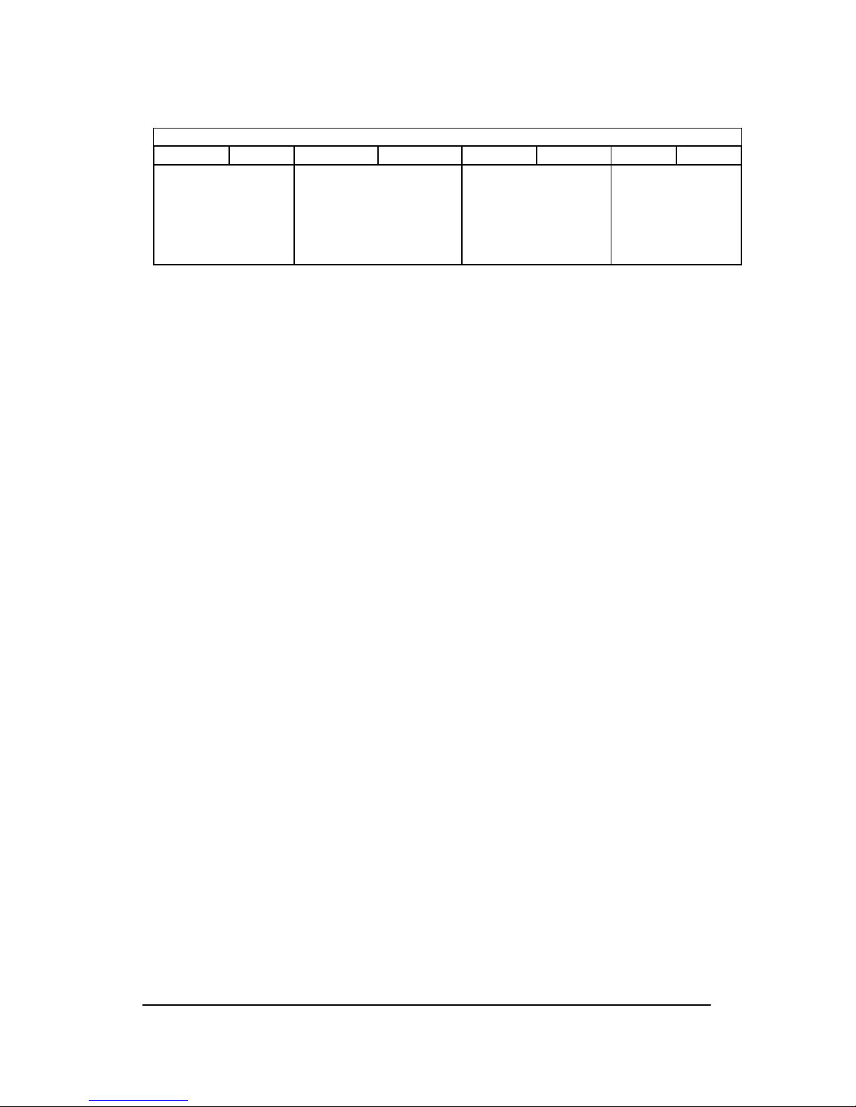
Alarm Connections
Function Terminal Contact Notes
A NC Closed in alarm state
B Common
Aggregate
Comms Alarm
C NO Closed when healthy
D NC Closed in alarm state
E Common
Power Alarm
F NO Closed when healthy
RFL SMX3 / 21 Page 20 of 22 Issue 1.4
User Manual
08 June 2009
14. Example Configurations
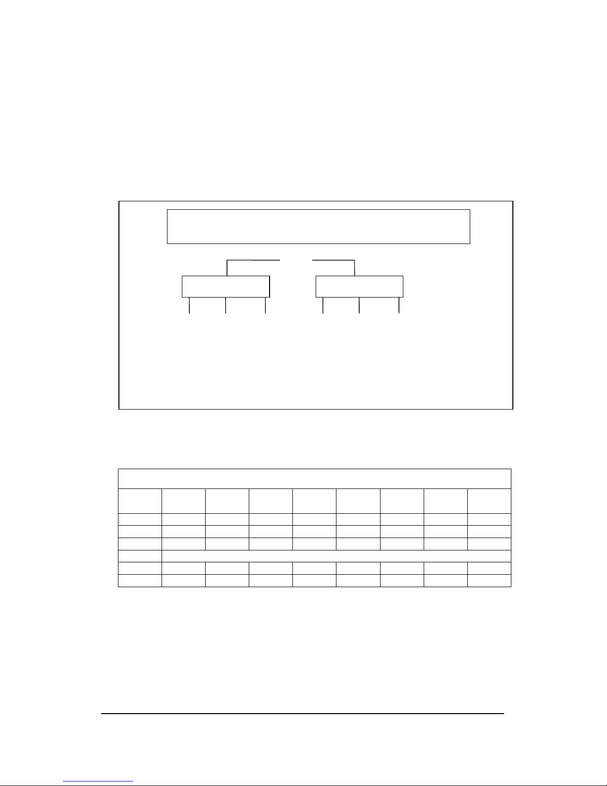
Example 1: X.21 synchronous data point to point and two channels of V.24
asynchronous data point to point.
This configuration assumes a master clock signal is provided by the X.21 links.
V.24 channels configured in Transparent mode.
DIP Switch Settings for both units
8 7 6 5 4 3 2 1
SW1 0 0 0 0 0 0 0 1
SW2 0 0 0 0 0 1 0 0
SW3 0 0 0 0 0 1 0 1
SW4 Not used
SW5 0 0 0 0 0 0 0 1
SW6 0 1 0 0 0 0 0 0
Substation A Substation B
X.21
A1
Example installation – Single X.21 and two V.24 channels
X.21 V.24 V.24
Ch A Ch B Ch C
Port Port Port
X.21 V.24 V.24
Ch A Ch B Ch C
Port Port Port
B1
RFL SMX3 / 21 Page 21 of 22 Issue 1.4
User Manual
08 June 2009
Example 2: X.21 synchronous data links point to point, and two V.24
channels concatenated over two links (e.g. X.21 protection relays and
SCADA network on two BT kilostream X.21 links):
Only possible on a well disciplined system, where only one terminal transmits at
one time. This configuration assumes that both X.21 links are running on the
same network master clock e.g. BT Kilostream. V.24 channels configured in
Transparent mode.
DIP Switch Settings for A1, C1
8 7 6 5 4 3 2 1
SW1 0 0 0 0 0 0 0 1
SW2 0 0 0 0 0 1 0 0
SW3 0 0 0 0 0 1 0 1
SW4 Not used
SW5 0 0 0 0 0 0 0 1
SW6 0 1 0 0 0 0 0 0
DIP Switch Settings for units B1, B2
8 7 6 5 4 3 2 1
SW1 0 0 0 0 0 0 0 1
SW2 0 0 1 0 0 1 0 0
SW3 0 0 1 0 0 1 0 1
SW4 Not used
SW5 0 1 1 0 0 0 0 1
SW6 0 1 0 0 0 0 0 0
Substation A Substation B Substation C
BT X.21
Aggregate Concatenation
Example installation – Protection & SCADA
A1
X.21 V.24 V.24
Ch A Ch B Ch C
Port Port Port
B1
X.21 V.24 V.24
Ch A Ch B Ch C
Port Port Port
BT X.21
B2
X.21 V.24 V.24
Ch A Ch B Ch C
Port Port Port
C1
X.21 V.24 V.24
Ch A Ch B Ch C
Port Port Port

RFL SMX3 / 21 Page 22 of 22 Issue 1.4
User Manual
08 June 2009
15. Blank Setting Table
Blank setting table:
Location:
Reference:
DIP Switch Settings
8 7 6 5 4 3 2 1
SW1
SW2
SW3
SW4
SW5
SW6
©2009
RFL Communications plc
Connect 17
Avon Way
Langley park
CHIPPENHAM
Wilts
SN15 1GG
www.rflcomms.co.uk
Installation and Technical Support:
Phone +44 (0) 1249 446500
Fax +44 (0) 1249 446506
e-mail support@rflcomms.co.uk
 Loading...