


pcProx® Plus, pcProx® Enroll
Wiegand
Configuration
User
C
onv
Utility
Manual
erter
99009010
&
Rev
A.5

2
Thank
You!
Congratulations on
RF IDeas hopes you enjoy using
Configuration
your business, school,
the
is
easy, so you
or organization.
purchase
will
of
your pcProx® Enroll, pcProx® Plus,
the
readers as much as
be able
to
quickly take advantage
we
enjoyed creating and developing
or
Wiegand
of
a more secure environment
device(s).
them.
in
Please call
Independent Developer’s
We
look forward
www.RFIDeas.com and
product
our
line.
Sales
department
if
you have any questions
programs.
to
your comments and suggestions
follow the
Support a Learning Center
for our
or
are interested
product
line!
link for
in our
OEM
and
Please go to
more details about
our
We
are always discovering new applications
developer’s licensing
Thank
The RF IDeas
you,
Staff
our technology so
Need
Assistance?
Ph: 847.870.1723
Fx: 847.483.
E:
Sales@RFIDeas.com
1129
TechSupport@RFIDeas.com
for our
the
solution you are looking
product
line(s).
There are several
for
may already be developed.
software

3
Glossary
Of Terms
ASCII: The American Standard Code
communications equipment, and
other
for
Information Interchange codes represent
devices
that
use
text.
text in computers,
Contactless: The high frequency
FAC: Facility
OEM: The
system
Access
proximity
integration.
Code
card and badge reader available
13.56
MHz smart
card technology.
in
self-contained electronic modules
for easy
pcProx Contactless: The registered
reader
products.
RF
IDeas brand name given
to all
13.56
MHz
contactless
card
pcProx
products.
Proximity:
The registered
RF
IDeas brand name given
to all
125 kHz
proximity reader
Proximity:
SDK:
command capabilities
The
low
frequency 125 kHz RFID technology.
Software Developer’s
to
integrate software applications
Kit.
Software Developer’s
Kits from
RF
to our devices.
IDeas provide
the
high
level

4
Contents
2
3
5
5
6 ID
6
7
8
8
8
9
9 What’s In
10
11
11
11
12
12
13
13
13
14
19
22
23
23
25 Output
26
28
30
31
35
Thank
Glossary
Chapter
Wireless Identification
Card Reader System
pcProx
Credential Form Factors
Card
Reader
pcProx Plus & Non-Plus Reader
Chapter
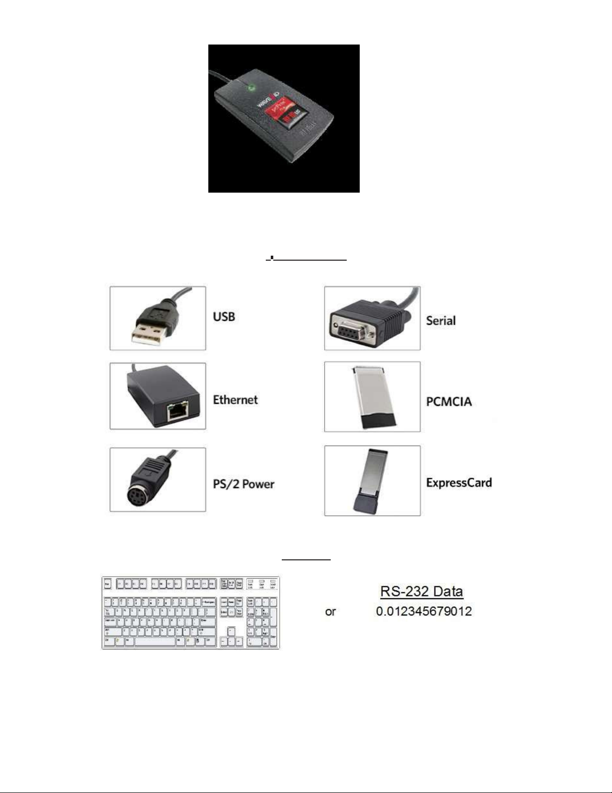
Interface
USB Readers
RS-232 Readers and
Minimum
Reader Set-Up
LED
Beeper
Chapter 3:
pcProx Configuration
Utility Overview
Menu Tool
Icon Tool
pcProx Plus
Standard
Connect
Data Format
Delimeters
Timing
SDK
Tab
CHUID
You!
Of Terms
1: The
Output Formats
Compatibility
Configuration Purposes
2:Hardware
Test
Tab
Tab
Basics
Overview
Your Part Number?
(Connectors)
and Wiegand
Converters
System Requirements
Basics
Software
Utility
bar
bar
Configuration
Configuration
Tab
Area
Tab
Tab
Differences
Converters
45
45
46
47
50
54
58
59
Chapter
ASCII
4:
ASCII Command Protocol
Overview
Connect Serial Communications Pr
Command
Help
Variable
ACP Error
Structure
Command
Command
Codes
Chapter 5: Tips and
59 Troubleshooting
60
63
63
63
66 Index
67 Appendix
69
Frequently Asked
Precautions
Before You Call Technical
Talking To The
Technician
Other Products and
Troubleshooting
Questions
Support
Accessories
ogram

5
The
Wireless Identification
Basics
Overview
1
pcProx® Activated
Employers are more security conscious than ever.
applications require identification information
access cards
to
Identification
be used as a digital identifier throughout
More
to
gain access. RF
buildings, machines, systems,
IDeas devices allow
the workplace.
and
the building
Various pcProx applications
•
Card
Enrollment
•
Application
•
Form
filler to
•
PC/LAN Log
•
Cafeteria Pur
•
Machine
•
PLC and embedded
•
Time/Attendance
Our pcProx Plus devices are easily configured
proximity
identification cards can also be used
authentication applications. Thus,
recovered.
and/or contactless technology
log-on
existing software
On
chases/V
Access
include:
ending
controllers
with the pro
the majority of
applications
to
increase security and reliability. Companies
for
building access
ximity/contactless
immediately benefit, as
device
deployment and enrollment costs are
for additional
their employee
using
quickly
The diagram on
sends
the
to
other software applications
RF signals
reader
separate
the
to the
in
keystrokes
the data.
following page
card and
or
ASCII characters. This card data can be configured
This reader can be used as a standalone system
using
is
a high level overview
the
card sends signals back
the
optional
Software Developer’s
of how the
to
send
reader
data.
or
Kit (SDK).
works.
The card data
to
include
seamlessly integrated
The
reader
is output by
delimiters
with

6
Chapter 1
The Basics
ID
Card Reader System
Output Formats

7
Chapter 1
The Basics
Credential Form Factors
Credentials are inactive electronic devices
start-up
contactless frequencies. Proximity
and communication. The credential
and contactless smart card technology cards allow users to
effortlessly manage multiple applications through a single
Data: The data on access cards are a string
length.
that
rely on readers
itself,
consists
of
binary numbers set
to
supply
of
antennas
credential.
with
the
required power
that
produce
proximity or
a fixed configuration
for
and
Frequencies:
(proximity)
Credential Form Factors:
are a variety
particular
RF
IDeas’ access control readers and credentials utilize
band and/or
of low
needs.
the
high-frequency
With
over
300 million
and high frequency
13.56
MHz
(contactless)
physical access credentials
form
factors customers can choose
the
low-frequency
band.
in
from to
125
kHz
use worldwide,
meet
their
there
The below illustrates some
of
the various
form
factors
available.
CSN: Also known as
operating
UID: The User
needed.
at the
the
Card Serial Number,
13.56
MHz frequency.
ID or
User Identification, can be encoded as data on
is part of the
ISO 15693 standard
the
card when a security key
for vicinity cards
is

8
Chapter 1
The Basics
Manuf
Please go
Reader
acturer/Vendor Card
to
www.RFIDeas.com
for
Configuration Purposes
Compatibility
specific device
part
numbers associated
to
card
types.
The method
each technology
access privileges
process
of
of the
encoding data on a card and transmitting data
involved.
for the
reader utilizing
The reader
itself is not
aware
cardholder. This information
the
supplied
software.
of the
is
only accessible through
to the
makeup
reader differs accordingly to
of the
card data
format or
the configuration
The reader
for the
case,
Differences Between pcProx Plus Reader Non-Plus Reader
is
very flexible and may need
user, such as, singling
hexadecimal).
out
FAC
to
be configured
or
ID, obtaining a desired base (i.e. decimal, lowercase,
in
order
to
present an exact desired
output
upper-
The pcProx Plus
t
echnologies
choice among
technologies.
is
a dual frequency programmable reader
into the
35
same reader.
It’s the
card types, delivering
only reader
flexibility to
that
combines 125 kHz and 13.56
in the
industry
that
reads
any customer struggling
two
with
cards
different
MHz
of your
card
In
contrast
function on a single frequency band, which
to the
pcProx Plus reader,
our
standard pcProx Enroll
is
either 125 kHz
proximity
proximity or
and contactless
13.56
MHz contactless.
readers

9
Hardware
2
What’s In
All
RF
differentiation between
Below
Reader
Your Part Number?
IDeas reader
is the
basic
part
part
RDR - 6 3 8
Type
Frequency Card
numbers
products.
number
follow a distinct
scheme.
Type
system
1
Model
of
categorization
A K U
Housing
to
allow
for
an ease
Color Interface
of
Housing
Version
Reader Type: The reader
a
kit.
type distinguishes between standard
reader, OEM, c
onverter, mag-stripe,
or
Frequency:
high-frequency
RF
IDeas’ access control readers are available
13.56
MHz (contactless).
in
low-frequency
125 kHz
(proximity) or
Card Type: The card type allows
compatibility
specific device
(Please
part
numbers associated
visit
www.RFIDeas.com, choose a product and locate
for the
selection
to
card
types).
of
over
35
different card types
for reader
the Part
Numbers
tab for
Housing: This option provides
housings include; desktop, wall
(For more on
form
factors, please
the
user
to
select
mount, USB dongle, PCMCIA, bare board, ExpressCard,
visit www.RFIDeas.com)
the form factor
housing
for the
desired reader.
The
or custom.
Model:
(13.56
Version:
Housing Color: The color category simply allows
housings.
The model selection corresponds
MHz
contactless only), playback (13.56
The version refers
(Applies only
to the
to
desktop and
selection
to the
wall
type
MHz
of
either
mount
of
reader, whether
contactless only), SDK,
our
standard
for the
selection
housings)
or
custom
of
either
it is
a standard,
or
build.
our
analyzer.
black
or pearl
writer
Interface:
This option specifies
the
type
of
connection
for the
reader (i.e. USB, RS-232, PCMCIA,
etc).
10
Chapter
2
Hardware
Interface
(Connectors)
T
C
ONNECT
OUTPUT
ORS

11
Chapter
2
Hardware
USB Readers
Minimum System Requirements
HARDWARE
Pentium class
PC
MEMORY
32 MB RAM
DISK
25 MB
hard disk
space
I/O
1
available RS-232
or
USB Port
Operating System
Any
operating system
that supports
a USB keyboard
including
Microsoft
Windows 2000®,
XP®, Vista®, 7®, Server
200
3®,
Server 2008®, Linux, Macintosh®. Can be used
for keystroke
applications
and Wiegand
Converters
The pcProx USB keystroke device operates
•
USB keyboard.
data on a
•
Under
card data,
keyboard.
the
the
It
reads
the
card data and sends
application programmer interface
active application receives
in two
the
primary
modes:
it
as keystrokes as
(API)
defined
entire card
in the
data.
if the
user typed
pcProx SDK.
the ID
When it reads
Note:
RS-232 Readers and
The pcProx ExpressCard operates as a USB reader.
Converters
The RS-232, Ethernet,
1.
ASCII
output
hexadecimal number
or virtual COM port
device.
In this
in
ASCII
mode
characters.
device operates
the
user card data
in two
primary
is
read and sent as a decimal
modes:
or
2. API defined
card data,
in the
the
active application receives
pcProx SDK. The device attaches
the
entire card
to
a computer serial
data.
port. When it reads
Once
the
configuration settings are correctly configured and
immediately be
deployed.
written to
flash
memory, the
device
can
Note:
Minimum
The pcProx PCMCIA operates as an RS-232 reader.
System Requir
ements
Note:
The software
read
to
verify
does
its validity.
not
perform any data validation checking. The data must be known before
it is

12
Chapter
2
Hardware
Reader Set-Up
Basics
Plug
the
connector
Ethernet
Place
plug.
the
device next
The workstation should detect new hardware
this
connection using Device
into the
to the
workstation’s
(or
monitor, beside
Manager’.
available on any peripheral) open
the
workstation,
for
USB
connections.
or
where
Verify the
appropriate.
RS-232, USB
workstation rec
or
ogniz
es
Verify the
When the
appropriate device. Once
not
have
LED
correct
software
to
be configured
Beeper
COM port for
is
installed,
the
device
again.
RS-232 DB9 connections using ‘Device
it
should recognize these connections
is
configured and
written to its
flash
Manager.’
in
order
memory,
to
configure
these settings
the
will
The desktop,
a
light
up LED on
Beeper functions
LED when a credential
USB dongle,
the front
in the
Software section)
is
wall
mount, and bare board
cover. The LED
detected
by the reader.
(OEM)
is
configurable through
to
allow
the
device
model readers are
the utility
to
produce a beep upon
software (See LED
all
equipped
light
up
with
and
of the

13
Software
pcProx Configuration
The pcProx Configuration
pcProx Plus,
credential data
In
contrast
reader,
for users.
Utility Overview
Menu
pcProx Plus
C
Output
Toolbar
(pg. 14)
onfiguration
Area
(pg.
18)
Test
Area
or
Wiegand devices
to the
the utility
output
Utility
Utility
and access privileges
pcProx Enroll readers,
allows
the
provides users
to
meet
pcProx Plus configuration process
with the ability to
their
needs. Through
for
cardholders can be
for
which only one configuration can be programmed
configure
the
configuration process,
established.
to
create
Icon
two
Toolbar
(pg.
their
separate
19)
pcProx
3
Enroll,
desired
into the
configurations
Standar
C
onfiguration
(pg.
Area
18)
d

14
Chapter
3
Software
Menu Tool
Bar
The Menu Tool Bar contains
all the
basic configuration options
for the
utility.
File
The
file
menu
Open
configuration settings
.Hwg
lists the
/.Hwg+
options
for
Opening .Hwg and Saving .Hwg
File: Opens either a .Hwg
for the
reader. The
utility
or
.Hwg+
comes
file. A
with
files.
.Hwg
sample
or
.Hwg+
file
contains
.Hwg/.Hwg+ files.
all the
Save
to
.Hwg+ File: Saves
What is a .Hwg/.Hwg+ file?
and .Hwg+ file. A .Hwg
sion. A .Hwg+
Plus reader as
file
well
the
configuration settings
There are
file
can only be created
two
can only be saved using
to the reader.
kinds
this
new
as a single configuration reader.
of
configuration files. There
with
previous pcProx application
utility . A
.Hwg+ can configure a
is
a .Hwg
utility ver-
pcProx
file
Exit: Exits
C
onnect
out of the
entire
utility
The connect menu provides options
Auto
utility
Connect
searches
to
USB on Startup: Set as
for
a USB
connection on
for
device
utility
star
to utility connections.
default connection. Through
tup.
this
connection
the
Auto
Connect
connections on
to
Serial on Startup:
star
tup.
With this
selection,
the utility
searches
for
any available
serial
Auto
Connect
Why
an easy auto connect through a specified
Connect: This selection has
connections.
Why
to
connect
interface connection. This feature cycles through
Note:
Toolbar section on page 19
to
Ethernet on Startup:
use
the Auto
Connect feature? The
the utility
use
the
Connect feature? The
their
device
to the
For further information on
Utility
option
utlity’s
port
search
utility,
for
a device connection through
utlity’s
general connect option gives users
without the
the
connect option, see
of this manual.
to
search
for
ethernet connections on
auto connect features allow users
on
star
tup.
all
available
user needing
all
available ports
to
identify
until
the
connect portion
the
a device
to have
the ability
devices
is found.
of the Icon
star
tup.
port
actual

15
Chapter
3
Software
(Connect
--C
ont.)
Connect
Connect
Connect
Disconnect: Disconnects
configuration
to
USB: Connects
to
Serial: Connects
to
Ethernet TCP/IP: Connects
Why
use
the
Connect to f
device through
switching
out
utility.
to
current specified reader through
to
current specified reader through
to
eature? The connect
the
specified
port
upon selection. This
and changing devices
all
connected devices
USB
serial
current specified reader through ethernet TCP
to
with
different
from
every available interface connection
feature allows
is
especially helpful when users
connections.
the utility to
connect
/IP
to a
are
from the
Note:
Icon Toolbar section on page 21
Device
Menu
For further information on
the
disconnect option, see
of this manual.
the
disconnect portion
of the
The device menu
device menu options are altered depending on
configuration reader device has different device menu options than a
lists the
options
for
resetting,
writing to,
the
type
and reading
of
device
the
that is
two
device’s data
connected.
memory. The
A single
configuration reader
device.
Single Configur
Reset
ation Readers:
to
Factory Defaults: Resets
all
configuration parameters
to
factory
defaults.
Read Settings: Displays
Write
pcProx Plus
Reset
Settings:
Note:
For more information on
Writes the
Active portion
- 2 Configur
to
Defaults: Resets
of the
Prox and RDR-758x Equivalent (covers
CSN, ISO 15693A CSN, MIFARE CSN, MIFARE DESFire
the
current connected device
current configuration settings
the Write
Settings option, see
Icon Toolbar section on page 21
ation Reader:
all
configuration parameters
5
different card types;
configuration
to the
connected
device
the Write Settings/W
of this manual.
to
defaults. Defaults are set as
HID
iCLASS CSN, ISO
CSN)
rite
HID
14443A
Reset
to
Stored Settings: This selection allows users
personally defined stored
settings.
to
reset
the
device
to their own
Write
Stored Settings:
Note:
Stored settings are defined as configuration settings created
set/written to the
writes the
current configuration settings
device through
the utility
as a stored
to
stored
settings.
settings
by
a user
and

16
Chapter
3
Software
(Device
Menu--Cont.)
pcProx Plus
Read Active: Reads
- 2 Configur
ation Reader:
the
current configuration. Active settings are
what
allow
the
device to
function.
Write
Note:
connected
Navigation Menu
Active:
Note:
Active portion
Writes the
current configuration
For more information on
of the
Icon Toolbar section on page 21
the Write
Device Menu options are altered when a
to the
utility.
to
active
Active option, see
settings.
the Write Settings/W
of this manual.
two
configuration device (pcProx
rite
Plus) is
The Navigation menu gives users
of hot
Area (An
manual).
keys. This menu
explanation
lists the hot
of
each
the ability to
key commands
tab
can be found
navigate
for the
in the
Standard Configuration Area section
in
and
out of the utility
tabs as seen on
tabs through
the
Standard
the use
Configuration
of this
For example, pressing
the
F5 key on
the
keyboard
will
open
the
Data Format tab.
a new
This command opens any
window. The Test
App
keystroking
default
opening
A
Test
App hot
capturing program (i.e. notepad, wordpad
program
is
key command
set as
notepad.
is
also available
in this list.
etc) in
View Menu
The view menu provides options
utility.
All the
options
in this
for
altering
menu are set
the
to
appear
appearance
by default.
of
certain functions
of the application
Show
Tooltip
Note: Tooltip
pointer over a
Balloon: Menu option
balloons appear
tool or
disappears when
seconds. The
mouse
is
tooltip
currently hovering over.
for
displaying
automatically, or
some other
the
user moves
UI
element. The
the
pointer away
displays descriptive information
or not
displaying
pop up, when
tooltip
from the
of the
the tooltip
the
user pauses
appears near
tool,
or
simply waits
specific element
pop-up
the mouse
the
pointer
or tool that the
balloon.
and
for a few

17
Chapter
3
Software
(View Menu--Cont.)
Show Text Under Toolbar Icons: Provides option
Toolbar (For more information on
the
Icon Toolbar, see
manual).
to
display
or
remove
the
Icon Toolbar section on page 19
text
under icons
in the Icon
of this
Show Pop-Up Warning Dialogues: Gives option
dialogue
boxes.
for
user
to
display
or
remove warning
pop-up
For example,
dialogue box, as seen below,
been
displayed to
if the
Show Pop-Up Warning Dialogues option
will
display on your screen. The below warning dialogue box
alert
the
user
that the utility
has
is
selected, then a
not
detected a connected
warning
has
device.
Show Confirm Dialogue: Menu option
utility
operations are
completed.
for
displaying yes/no confirmation dialogues before
certain
For example,
window
if the
Show Confirm Dialogue option
will
appear when a user clicks
to
reset
is
selected, a confirmation
their
device
to
factory
dialogue
defaults.
Note: If the
continue upon user selection
Beep On Warnings: Provides an audible system beep when warning are
Note: With the
Pop-Up Warning Dialogues option
Resize Window: The
window larger
Area).
window
If
a user resizes
to its
Show Confirm Dialogue option
without the
Beep on Warnings option,
or
smaller
original
utility
window
(the
the utility
size.
is
designed
smallest resize choice
window, clicking
is not
selected,
need
for confirmation.
the
audible beeps
is not selected.
for
users
to
will
eliminate
this
Resize
all utility
operations
detected.
will
sound even
optionally resize,
the
view
of the Output Test
Window
option
by
making
will
will
if the Show
the
resize
the

18
Chapter
3
Software
Help
Menu
The help menu provides options
and/or
device.
for
which users can seek
out
additional assistance using
the
utilit
y
Read User Manual: Opens
configuration
utility.
the pdf
user manual
that is
bundled
in the
download
with the
Note:
utility
www.RFIDeas.com: This operation
Check Website
IDeas
pcProxConfig
download.
The user manual can also be found
was
installed.
will
for
Software Updates: Clicking
software updates portion
utility is
currently
of the
in
use.
in the
directory folder
open a new window
this
option
website, and
Any
updates
will
that
detect
to the
will
RF IDeas
take users
what
version
are available
in
will
which
the configuration
website.
to
a location on
of the
be listed
for
the
easy
RF
user
About: This selection’s menu options
there
is
no device connected.
displays
the utility
provided. The
version.
RF IDeas Tech
Without
When
support email and website
differ
when a device
a connected device
a device
is
connected,
is
connected
the
about informational content
the
firmware information
to the utility
address are displayed
vs.
when
simply
is also
in both modes.

19
Chapter
3
Software
Icon Tool
Bar
The Icon Tool Bar contains
are also found
write
settings and
C
onnect
in the
write active).
the
three most general configuration controls
Menu Toolbar under Connect
(for
connect and disconnect) and Device (for
for the
utility. These
controls
Clicking
port connections.
the
Connect icon
button
commands
the utility to
search
for
a device through
all available
Once
the utility
Configuration Area displays
nected device. The model number
the Output
detects a device connection,
the
interface connection, firmware and LUID information
Test Area
will turn from
of the
gray
the
Device List pull-down menu
device
will
to green.
be displayed below
in the Standard
for the con-
the
Device List pull-down
and
Note: More
devices, select
Device
Number
than one device can be connected simultaneously
the
Model
desired connected device
from the
to the
utility. To switch
Device List pull-down
between
menu.
Device List
P
ull-down Menu

20
Chapter
3
Software
(Connect
--C
ont.)
If
an
attempt to
the
available interface connections, a
bar
area.
Status
Bar
connect
to
a device
is
made and
“no
devices
the utility
found”
message
does
not
detect a device through any
will
display
in the utility’s status
of

21
Chapter
3
Software
Disconnect
Clicking
through any and
the
disconnect icon
all
available
button
commands
port connections.
the utility to
disconnect
from all
devices
connected
Once
the utility
and device model number are cleared
Area
will turn from
Write
Settings/Write A
disconnects
green
to
ctive
from all
available device connections,
from the
Standard Configuration Area and
gray. Additionally, the
status bar
the
Device List pull-down
the Output Test
will
display a “Disconnected” mes
Status Bar
Mes
sage
menu
sage.
The
Write
to the
configuration device (pcProx Plus),
or two
will
change
Settings icon
device. Since
button
the writing
configuration device
to
read
“Write
prompts
options
is
connected.
Active,”
the utility to write the
differ
between a single configuration device and a tw
the Write
Settings icon
When a two
as seen
below.
current defined configuration
will
change depending on whether a
configuration device
is
connected,
settings
o
the
icon
single
text

22
Chapter
3
Software
pcProx Plus
This section
connected
Configuration
is
only available
to the
utility.
to
configure selections when a
two
configuration device (pcProx
Plus) is
Note: When
Configuration area
a single configuration device
is
grayed
out
(as seen
is
connected
below)
to the
utility,
and selections
the
pcProx
within this
Plus
area are
not possible.
Configuration
The pcProx Plus Configuration area allows
device. The configurations could be either one
13.56
MHz. The configurations can also be
configuration settings,
the HID
Prox and RDR-758x Equivalent (covers
for
users
to
set-up
two
125 kHz and one 13.56 MHz,
of the
same card type. The device
different configurations
or two
is
set
5
different card types;
iCLASS CSN, ISO 14443A CSN, ISO 15693A CSN, MIFARE CSN, MIFARE DESFire
Note: If
to
configuring
read only
#
26 bits
the
and
system
the
for HID 26 bit
other configuration
and
HID 35 bit,
to
read only
remember
35 bits.
High Priority
to
set one
(Number)
Card Type
Dr
op-Do
Configuration # (Number): This option provides
Users can set and
Card Type Drop-Down Menu:
settings,
the HID
desired card
separate card
edit
settings
for two
As
Prox and RDR-758x Equiv
type
for their own
configuration settings.
types.
stated above,
High Priority: Provides a pcProx Plus user
priority
combination
preferred over
The High Priority bit
the
than another. This is useful when
of
13.56MHz/125kHz cards as
the
other.
reader
will try to
increases
read
that
the time it
card type
wn
the ability to
switch between configur
separate configurations quickly and easily.
the
device
is
set
with two
default
alent. This drop-down menu lets users choose
Each
configuration has
the ability to
the
user has a population
well
takes
to
10 times before switching
give a certain configuration a
of
cards consisting
as single-technology cards, and one
read
the
card.
When the
to the
High
other
for their
125 kHz and two
with two default
HID
CSN).
configuration
ations.
configuration
the
the ability to have
higher
of a
of
those
is
priority bit is set,
configuration.

23
Chapter
3
Software
Standard
Configuration
This Standard Configuration area provides
connected
device.
all the
options and details necessary
to
configure
a
USB
Ethernet
Connect
The connect
different selections allow
Tab
tab
offers
the
various ways a device can connect
the
user
to
choose
the
connection type
to the
for the
configuration
specific logical protocol
their reader.
Serial:
and Vir
utility.
COM
The
RS-
232
tual
of
Note:
USB: Make
proceed
Only one connection type
this
selection
to
scan any available USB bus
if the
connected device has a
at a time will
for
connected
be
shown.
USB
logical protocol. The
devices.
utility will then
Serial: RS-232 and
COM port
port
logical protocols
devices,
Virtual COM
to
virtual COM port
Ports: This option provides devices
connect
devices, including
to the
utility. This section scans
USB,
CDC and PCMCIA
that
are RS-232
for
or Virtual
RS-232, physical
devices.
COM
When
set. The
making
port
this
selection,
values range
the
lower and upper
from 1 to
limits of the COM
256. The default
COM
ports
ports are set
to
scan need
at 1 thru 8.
to be
Default
Note:
1..8:
This option sets
the COM port
values back
Serial devices may slow when scanning a wide
to the
default
port range.
of
1 and
8.

24
Chapter
3
Software
(Connect
Tab--Cont.)
Ethernet (Local IP 10.10.10.65): Connects
a TCP/IP on
be entered
the
given port. The
for the
interface
first,
to
connect
to
an Ethernet reader
second, third, and
to the
reader. The IP
fourth
port
at the
byte
number
given IP address and
of the
TCP/IP address need to
will
also be
open
required.
Port Option:
number
Note:
Find Next IP Button: Looks
Allows for
changing
Ports below 1024 are
for
other readers on
the port
for
system use
location.
the
Xport port
location needs
only.
same ethernet c
onnection.
to
match
this
Device List Pull-down: Lists
For Example,
connection
if
you have an RJ45 connector (as seen
to
be selected
the
devices
is Ethernet.
that the utility is
below) then
actively connected to.
the
specific logical
protocol
Note:
USB.
logical protocol connection
part
Remember,
If
your device has a USB connector, and your device
number suffix
not all
of
xxU
USB
interface connections do
is
made through COM. A device
will
connect through
C
ONNECT
the
not
necessarily logically connect
part
number suffix
with a
USB connect
ORS
USB
option.
through
is xx0 or
xxF,
the
interface connector and
a

25
Chapter
3
Software
Auto GetID
Output
This
unsolicited serial
The
displays
Card
The
device.
Test
Area
is the test
area
Auto GetID
the
results directly under
Data
Auto
Focus box keeps
for the
port data.
box can be checked
Note: When the Auto
menus and drop downs, due
area. If this
The
Auto
Clear box auto selects
the
device
The Clear
clear
button
button.
The Test button (Gr
users
own
problem arises, simply uncheck
will
replace
erases
een F
application
(i.e. notepad, wordpad
keystrokes entered
for the utility to poll the
the
checkbox, as seen
the
cursor
Focus box
in the test
is
checked,
to the fact that the
all text in the Output
old text.
all text in the Output
lag)
to
starts
view
the
batch
the
readers keystrokes.
etc).
F
ocus
Auto
by the
reader. On serial devices
area box
it is
possible
cursor
the box.
Test Area, so
Test Area each
file
“testarea.bat”
It
Auto Clear
C
lear
this
displays
reader
below.
to
capture
that the
will attempt to
time the
for
the
that
or script
a card
selection may
ID
every 500msec
keystrokes
move back
output by the
conflict with the
into the test
new keystrokes
user manually presses
“testarea”
to
bring up
opens any keystroking capturing
Test
Button
the
output by
the
a
program
and

26
Chapter
3
Software
cilit
y
Status
Bar
The status bar
doing, as
Data
Format
(below the
well
as connections and disconnections between
Test
Area)
displays various messages
Status Bar
Tab
to
the utility a device.
alert
the
user
of what the utility is
This
tab
provides users
utility.
ABC = Pre-Card
ID
Delimeters-
Characters
Max
the ability to format how the
987654321
Card
3
=
ID Value
data on a card
T = Termination
Char
will
be keystroked
acter
GN = Card Gone
Char
(When
leaves
out by the
acters
car
fields)
d
123 = Fa
Access Code
(FAC)
XYZ = Post
ID
Delimeters
(
Shared with
Pre-Card ID)
The above diagram illustrates
connected
device.
the
various characters
that
Car
d
can be displayed upon a card detection
by a
The number portions
The
letter
portions
utility
and are keystroked
of the
of the
diagram are values
that
are displayed
character diagram are values
from the device.
that
are formatted
from a card.
by the
user through
the

27
Chapter
3
Software
Wiegand
to
Keystroke Data Format
Strip Leading and Trailing
users have
counts can be set
Send FAC
the
option
to
to strip
range
: (Facility Access Code) Allows
Bit
Count: By altering
and discard
from 0 to
15.
the
bits from the
for
option
numbers
in the
leading and trailing
card data. The leading and trailing
to
display
the
FAC
code
bit count,
bit
Send FAC as Hexadecimal Number:
as a
decimal.
Will
send FAC as a hex number. The default
is
set
to output
Send ID: This selection keystrokes
Note:
parity bits.
When
checked uses
out the ID
the
defined
portion
of the
ID field bit
card
data.
count bits.
When
unchecked uses
all non
Send
ID
as Hexadecimal Number:
Will
send
ID
as a hex number. The default
is
set
to output
as
a
decimal.
ID
Field
Bit
Fix length FAC/
FAC Digits: This
Count: Sets
ID
will
the
number
of bits in the ID field from 0 to 80
Fields: This option
alter
the
FAC
output by
will
make
the
FAC and
forcing a set length
ID
a fixed
of
length
digits, between
0 to
32,
to be
displayed.
ID
Digits: This
displayed.
Advanced
Settings
Only Read Cards
specified
255
bits.
Display Hex
Note: The Send FAC as Hexadecimal
this
will
alter
With
bit
number. The
in
Lowercase:
option can be
the ID output by
This
Bit
Count: Select
bit
number
Will
is
display hex
provided.
forcing a set length
this
specified
in
lowercase
or
Send
option
in the
to filter out
box
format.
ID
as Hexadecimal must
of
digits, between
cards
to the right
0 to
32,
that
are
not the
and can range
first
be selected
to be
from 2 to
before
Use Numeric Keypad: Defines which keypad
AZERTY Keyboard Shift
AZERTY
keyboard.
Lock: This selection
will
be used
(whether
will output the
data as
across
if it
were being
the top or with keypad)
output from an
28
Chapter
3
Software
(Data
Format
Tab--Cont.)
FAC Extended Precision
amount
of bits to
provide appropriate
Math
On: Interprets
info.
the
FAC data
from
a card
to
allow
for the proper
ID
Extended Precision
of bits to
provide appropriate
Math
On: Interprets
info.
the ID
data
from
a card
to
allow
for the
proper
amount
Reverse Wiegand Bytes: Reverses data
in
byte chunks
(8 bits = 1 byte)
Reverse Wiegand Bits: Reverses each
Invert Wiegand
Bits: Inverts each
Emulate ProxPro-Append Serial Checksum: This option
the
end
of
serial data.
sending a 2 byte checksum
It
emulates
after
bit
the
the
card
bit
serial data
data.
is
format to
only
match
for
serial devices.
HID
Corp. Prox Pro reader
It
adds a
digit to
by
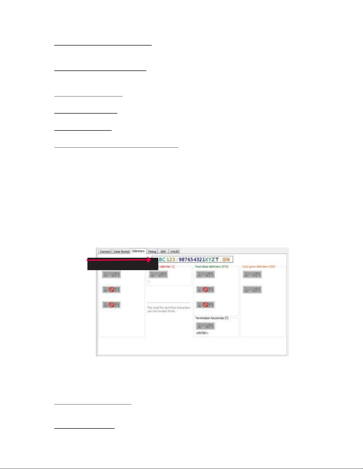
Delimiters Tab
Use
this tab to
FAC card
Click
the
ABC = Pre-Data
: = FAC/ID
configure pre and post data delimiters. A delimiter can also be set between
data.
appropriate keyboard icon
to
select
the
appropriate corresponding
delimiters.
the ID and
Note: Only 3 pre and post delimiters
delimiters can be
set.
total
can be configured.
If 3
pre-delimiters are set, no
post
Pre
Data Delimiters (ABC):
data. These characters are shared
FAC/ID Delimiter
(:):
Select
from 0 to 3
with the
Select a character
characters
post string
to
display between and separate
to
display
of characters.
at the
beginning
the
FAC and
of the card
ID data.

29
Chapter
3
Software
(Delimiters Tab--Cont.)
Post Data Delimiters (XYZ): Select
These characters are shared
with the
from 0 to 3
pre string
characters
to
of characters.
keystroke
to the
end
of the
card
data.
Termination Keystroke
card
data.
(T):
Adds a keystroke
to the
end
of the
card data
to
signify
the
end
of the
Card Gone Delimiters (GN):
removed.
Delimeter
The Delimter Keyboard
Keyboard
is
used
Left Click : To select desired delimter (key)
Left Double Click: To select desired key and
Right Click: Toggles between keeping
Adds a keystroke
to
select user defined delimeters (keys). Once opened users
to the
end
of the
card data when
the
Sp1, Sp2, Sp3
the left
auto insert
Shift
on
(the
or off
Insert button will
also
card
Special
insert
is
=
Keys
can:
the key).
The selected delimter keys
<NONE>. Once a chosen delimter
Revert: Takes user back
<None>: Deletes any selected/inserted
Insert: Applies selected delimter
Note:
be defaulted
Depending on
to
desired delimiter key.
will
highlight and appear
is
inserted,
to
previously
inserted delimeter
delimter
to
be
used
the
type
of
device connected (i.e. serial,
highlight upon opening
in the top left
the virtual
keyboard
corner
that is initially labeled
will close.
choice
FIPS201,
the
keyboard. To deselect, simply toggle between
etc.), certain keys
may
your
Special Keys--Sp1, Sp2,
There are some additional measures
to
reproduce passwords, such as,
that is difficult to
Sp1, Sp2, and Sp3 on
see page
54).
The Sp1, Sp2, and Sp3 keys are used only
unprintable characters
Sp3
that
can be taken
by
adding additional keystroke characters
re-produce, while configuring
the
delimeters
to
a specified
Virtual
Keyboard (For more information on Password
application.
to
make
it
more
difficult for
to the
the
data. These additional characters are labeled
for
keystroking environments
unauthorized
card
to send
users
information,
as
Security

30
Chapter
3
Software
Timing Tab
Use
this tab to
Card Data Hold Time: This option allows
wait
before
remain green
configure
the
device
after a card
the
device’s card
is
able
read).
to
read
timing
for
the
next card
and USB keystroke
users
to
determine
in
line
(which is
timing.
in
msec’s
also
how
how
long they need to
long
the
LED
will
The
timing
default
options can range
is
set
to
1000.
from 50 to 9950
min/max (50msec increments
only)
and
the
Note: This
Continuous
low the
data
Lock-Out Time
Must
be equal
is how
long
the
data
is
available
Read, Sends Data Upon Read:
to
be sent c
for
to or
ontinuously.
Repetitive Reads: The
greater than
the
hold
time that it
When
time
for the
a card
and
is
SDK
user.
is
placed on a device,
takes
the
reader
only done
in
to
read another
50msec
this
option
card.
increments.
will al-
Note:
hold
For a 2 configuration device (pcProx
time.
Plus) the
lock-out
time is the
same as card
data
to 0,
the
is 0. The
reader
is 20.
maximum
will output as
Key Press Time: The length
is 640. The default
is 20.
Key Release Time: Enter
fast
as
it
can go. The minimum value
of time the
the time
key
is
held down. The minimum value
delay between keystrokes.
is 0. The maximum
is 640. The default
If
set

31
Chapter
3
Software
SDK
Function
Description
Disable
Keystrokes
for
SDK
(Halt
Keyboard
Send)
Check
to
disable keystroking.
When
keystroking
or unsolicited
serial
out is
disabled,
all
card data must be read via
the SDK
functions.
Function
Description
Auto
Select
this to
make
the
device set
the
LED color.
Off Select
this to
set
the
LED
to off
Red
Select
this to
set
the
LED color
to red.
Green
Select
this to
set
the
LED color
to green.
Amber
Select
this to
set
the
color
to
amber.
Tab
Use
this tab to
keystroking.
configure
the
Software Developer’s
Kit (SDK) functions, as
well
as enable and
disable
LED
The LED section allows users
Software Developers
regarding
the
card
Kit
data.
to
control
the
LED
light
actions on
the
device
to
provide users
info

32
Chapter
3
Software
Function
Description
Enable Beep on Card
Read
Check
this to
set
the
device
to
beep when a card
is read.
Beep
Now
Press
to
listen
to the
beep
the
reader
will
provide when
in
use.
Long
Beep(s)
Check
the
box
to
configure a long beep
of
375 msec. By
default
the
beep
is set
to
a short
beep
of 125 msec.
2 long
beeps
or 5
short
beeps are allowed
only
Beeper On
(Output Active Low)
Check
this to turn the
device beeper
on.
Relay
On
Check
this to
activate
the
OEM
board.
Logical
Unit
ID: A user defined 16
bit
Logic
Unit ID to identify
one device
from
another.
Beeper
The number value
beeps
OEM Converter
to
produce when
Function Description
input
Board
area
to the right of the
the
device
is in use.
Long
Beep(s) box
is
designated
for the
number
of

33
Chapter
3
Software
ID
Function
Description
GETID
Click while scanning a card over
the
device. The
ID
displays under
the
button. This returns
64 bits maximum.
GETID
(32)
Click while scanning a card over
the
device. The
ID
displays under
the
button. This returns 255
bits maximum.
GetQueuedID
Click
to
display
the
last card data read. This returns 255
bits maximum.
Clear
Lockout
Check
to
clear
the time
remaining
to
allow
the
device
to
read
the next
card
immediat
ely.
Clear
UID
If
clearUID
is
set,
the
card and
the
over
run
counters
will
be cleared
for
the
next
read.
If
clearHold
is
set,
the
reader
will
be ready
to
read another
card
immediat
ely.
Display
Card
GETID Data
The
Most
Significant Byte
The Least Significant Byte
GETID(32) Data
Display
is first – 79
is
last –
A1.
.

34
Chapter
3
Software
GetQueuedID Data
Display
HH:MM:SS
displays –
00:00:06

35
Chapter
3
Software
CHUID
Function
Description
Define Fields
Click
to
select
the
number
of
source
bits to
define
the
fields.
The
correct type must
be selected
to
allow
for all
card
bits to
be
manipulat
ed.
Enable
Check
to
enable
the
highlighted field. This allows
the
delimiters
to be
output
and
the
corresponding card
field to
be processed and output.
All
green fields are enabled.
All
red fields are
disabled.
Keyboard
Click
to
select key delimiters
that
are stored
in the
device’s flash
memory
that
precede card data output. Each
field
may have
from 0
– 14
key
strokes.
C
lear
Click
to
clear keystrokes preceding
the
card
data.
Decimal
Click
to
display
the
card
field in
decimal
format.
Hex
Click
to
display
the
card
field
as a base 16 number
in
uppercase
HEX
0 – 9
and A – F.
BCD w/ Parity
Displays
the
card data
in
binary coded decimal, where each
5 bits
represent
1, 2,
4, 8,
and
parity. FASCN data
is
always odd
parity.
Tab
This
tab
allows manipulation
or proximity
change
cards. Use
the
order displayed
of all
the
red buttons
in the
fields on
to
binary
bit
the
Federal Information Processing Standard
(FIPS) 201,
configure additional fields. The fields can be moved to
pattern
display.

36
Chapter
3
Software
Function
Description
Advanced
Click
to
display
the
binary
bit pattern.
GetID
Click
to
display
the
binary
bit
pattern captured
from the card.
Start
Bit
Enter a number
to
define
the left
most significant starting
bit for the
field.
Bits Enter the number
of bits to
add
to
the
Start
Bit
to
define the range
of bits
in the field.
Digits
This
is the
number
of
digits
that will
display
in
a selected
field.
Up
Click
to
move
the
highlighted
field
up one
position.
Down
Click
to
move
the
highlighted
field
down one
position.
Advanced
This displays
Click each
Personal
pattern
bit
with
card data, click Clear
Button
the bit
field button to
ID
starts
is
highlighted. This
Parity). This
ranges
of the card.
display
at bit
111,
is 50 bits
is the 245 bit
to
remove
the
location
of the
long, and
output format is
configuration.
If
them.
card binary data.
is
10 digits. The
displayed
in
Bit
binary coded decimal
In the
Range
example below,
is
111
.. 160 and
with parity (BCD
any additional keystrokes were entered
the
the card
to
precede
the
Note: The message
above
the
Advanced
configuration is: “Keystrokes:
keystrokes maximum.
The
Bit
Range
Bits
field total
that
displays
button is
All
that
displays
– 1.
the
number
determined
8 of 32
fields share
to the left of the
bytes used. Room
96 bytes.
of
bytes used and
by the
device’s flash
binary
bit
for
pattern
how
much room
memory. In this
14
keystrokes.”
is the
Start Bit field total + the
for keystrokes
example
Every
field is
the
15

37
Chapter
3
Software
Get
ID
Click
GetID
and scan
interpretation display
the
card
of the
to
display
the output format of the
card data. Click
GetID to
define
FIPS 201 and
the
fields
to
set up
proximity
the device.
card and
the
In this
agency data
example, The Agency data starts
is
highlighted
in the
binary
at bit
11,
bit
pattern. The
is
16
bits
Bit
long, and
Range
is 6
is 5
..
digits. The location
25.
of the
The actual card data displays
card
data displays
in
red changes based on configuration settings flashed
Note: Click Clear
in
red
to
delete
in
blue below
in the text
the
red card data
the
binary
field. The card data
in the text
bit
pattern layout. The interpretation
in
blue
will
always be
the
same. The card
to the device.
field. A confirmation message
will
of
display.
the
data

38
Chapter
3
Software
The Start Bit
changes
the
actual location
of the
selected
field
on
the
binary
bit pattern.
Note: The ‘????’
the
correct
that
display
field is selected.
to the right of the
Digits
field
indicate
the
BCD
parity is
incorrect.
Verify

39
Chapter
3
Software
Change Fields
lr
Define Fields
/ [1] Enable Keystrokes below precede ca rd dat
a
11
<-E=NTE= -
------- ----- .
I
B
I
Creden tiil
Num. ]
K e
ys.
[
Credential
Series
]
[I!Credentiil
Issue]
I
Org. Category
]
IOrganizational ID I
Keystrokes
:
7 of
50 bytes used. R.oom for
14 keyst rokes
.
[ Person/Org.10
]
,---
:-:;c:c
FOS Bit 190
Decimal
t)
HEX
@ BCD
W
I
Par
ty
I
,..
Advanced
I
I
Bit Ra nge
:
3
1..
50
e7EB
F09
Bi t 235
FlO
Bi t 235
F11Bit 245
F12 Bit 245
F13 Bit 245
F14 Bit 245
F15 Bit 245
0Auto focus
]I
Unti tl
ed - Notepad
=
@J iooo!Joooj
l
1 File
Ed;, _Fo<m_•t _v;
..,
H-e--l'p
----------------
71
5002
9
1
1
1
7762
1
.
0/0,0000
Configuration
Click on the
In the example
Additional function
appropriate
below,the
keys display to configure more
field
button
Agency,
and uncheck
Persona liD,
Enable
to remove field data from being
and Expiration Date fields
fields.
have been
displayed.
removed.
40
Chapter
3
Software
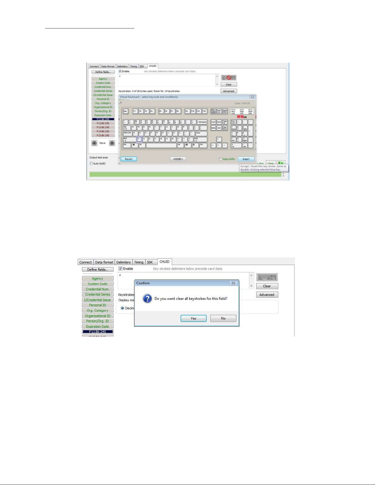
Assign Preceding
If
Enable
is
Keystrokes
checked
for
a field, specific keystrokes can be assigned
to
precede card data
output.
Note: The Scan Code
Click Clear
to
remove
output for the
all
preceding keystrokes as
key selected displays above
the list of keys.
appropriate.

41
Chapter
3
Software
Each
single keystroke entered to precede card data equals1 byte of
memory.
Connect Data format Delmi iters Tming
I
Define
fields.,
] Enable Key
SystemCode
credential...,,
Oedenbai Series
I/Qedenl lal!ssue
Personal
o-g. Category
Or
oarlza OOnal
Petson}Org.ID
E
xp
:
#
:
:igra:t:
F13Bit245
I
I
Keystrokes:
I
Display
ID
I
0
I
ID
I
Where
I
ion
Start bit--
Date
1Virtual Keyboard· select
Dedmal
4
o
mode
0Hex
SDK CHU
strokes
f
26
by tes used.Room
Number of
keycode and modif er(s)
D
c_----------------------,
delimiters below
@ BCD
bits
for 14
+parity
precede
keystrokes.
Digits
card
data
to di
splay
0
·
I
Advanced
Code:
I
0}1)004
Output
O
Ready
A utoG
Move
test area
eti
D

42
Chapter
3
Software
245
If any special character is selected with a keystroke, this equals 2 bytes of
memory.
Connect Data
I
Oe
fne fields.. - - '"==-
SvstemCode
Credential
Nun.
Credential
series
IJCredential
Issue
Person ai.ID
Org.
CateQOf" y
Oroar!zational
Person
}Qrg.10
Expi"··-·
tDMea;;
FllBit
11tualKeyboard -
F12Bit 24S
F13Bit245
Fl4Bit 24
Fl
5Bit245
liJ
Move
OJ!put
test area
[J Auto GetiD
format De
limiters
<
SHIFT+a
Keys
b"okes: 4 of 26bytesu
Displa y mode
Decimal Hex @
ID
Where
Star t bit
S
r ll'l'ling SDK CHUID
e
K_eY'_t_
>
Number
se:le:ct keycode: and modifier(s)
c_----------------------,
roke _d_eli_mit_e" _b_e
_w_p_re_<_ede <a_rd_d_ata
_
[BliJ
sed.Room
fur 14
BCD +parity
of bits
keystrokes.
Digits
to d
Bit R
i
spla y
ange:
0
6 ..25
[
E:3
ill
Advanced
I
Ready
[]
Keepshifu

43
Chapter
3
Software
If all the
keystrokes have been assigned
to the
fields,
the
following message
displays:
Depending on
example,
if the
the
active document/window, additional functionality can be assigned
card data
is
read
in
OpenOffice,
the
Note feature can also be
assigned.
to
a field. For
Select
Click Insert. Click Flash
OpenOffice. Scan
The value assigned
the
appropriate field. Click
the
card. The Notes function opens when
to the
the
to write this
function key
keyboard icon. Check Left Control. Check Left Alt.
configuration
in the
active document/window determines
to
flash
memory. Verify the
the
card
active window
is read.
the output.
Click n.
is
Note: This configuration
can be opened and deleted
file
utility
creates a ComSpecPort.txt
at will.
file
and saves
to the
default
dir
ectory. This

44
Chapter
3
Software
FIPS 201 Card
Configuration
In
order
to
configure a
•
Click Advanced
format
•
•
•
•
The Advanced
•
•
•
•
Click
GetID
Define
the
Configure any additional fields as
Flash
the
configuration
button displays:
Start bit location
Number
Number
Location
of bits for
of
of the field within the 245 bit range
FIPS 201
to
display
and present
fields
to
match
a specific
digits
for the field
card:
the
card data
the
card
to the reader
the
specific
appropriate
to memory
field
in the
output
binary
bit
pattern
to
determine
bit
length
and

45
ASCII Command Protocol
4
ASCII
Overview
ASCII Command Protocol
application. The serial Prox communicates using ASCII commands. Printable ASCII commands
9600
baud, no
parity 1 stop
(ACP) allows
bit,
and no echo, can be sent
the
user
to talk
directly
to the device.
to the
device
without
a DLL
or special
at
Note: USB devices
the
device and executed when a carriage
unit
then parses
code.
“\r\nRF
command
line.
All
Determine the
Windows
Use device manager
open
commands begin
COM Port
the
newly installed device
that
are
virtual COM port
the
command and performs
IDeas>” where
with the
to
display
\r
prefix
the COM
that
do
not
need
return (CR)
the
operation, and displays
represents a CR and
rfid:
and end
ports. Open
was
created.
with
the
baud rate set. The
or
line feed line feed (LF)
\n
represents a
a Return key, CR
the
serial
COM
LF
port.
the
that
or LF.
input is
is typed.
results
displays on
If it is
or error
a CDC
buffered
The
the
virtual port,
by
Linux
Most
Linux distributions include Minicom. Download
the
serial device
if Minicom is not available.
putty (www
.putty.org
) to
communicate
with
After the
/dev/ttyACM1
/dev/tt
ln -s
USB CDC device
is
found
yACM0 to /dev/
/dev/ttyACM1 /dev/modem.
is
enumerated on
in the /dev/
modem using
the
dir
ectory. Minicom
the
command
Linux machine a device
users may have
ln -s /dev//tty/A
CMO /dev/modem
of
either /dev/ttyACM0 or
to
create a symbolic
or
link from
Mac
OS
X
The /dev/
device.
cu.usbmodemf
a211 device
is
found on a
Mac
OS X . Use
putty to
communicate
with this

46
Chapter 4
ASCII Command Protocol
Connect Serial Communications Pr
ogram
Open
putty.exe. Click Connection a Serial
bits to
1, and
Parity to
None. Flow
control is not
and set
the
needed as there
Speed
(baud) to
is
no software
9600, Data bits to 8, Stop
or hardware
handshaking.
Click
Ses
sion.
Note: Use Hyper Terminal instead
of putty with the
XP operating
system.

47
Chapter 4
ASCII Command Protocol
Highlight
the
appropriate session. Click Save. Click
Apply.
P
utty
opens. Type
of
Help command
rfid:help
output is
and press
found
in this
Enter. The Help command
section
of the
Configuration User
output
displays. The complete
Manual.
list
Command
Structure
Commands are
·
All
commands begin
delimiter character between multiple
·
Functions must end
·
Variables can be assigned a value
question
·
Any
·
The Escape key cancels a command.
The general syntax
not
case sensitive. Characters assigned
with
a prefix string followed
with
a CR
or LF.
mark.
control characters other than
is:
by
tokens.
with
an equal sign followed
CR, LF,
and backspace
to
variables are case
one
or
more token strings
by the
terminate
sensitive.
with a period
value
or
queried
the command.
with a
PREFIX TOKEN { DELIMITER TOKEN
The prefix string
is rfid:
} { {
=Value} | {?}
}

48
Chapter 4
ASCII Command Protocol
Command structure falls
1.
Perform a
2. Assign a
3. Query a
Perf
orm a
A
function performs an operation
queried.
An
rfid:cfg.write CR.
function.
variable.
variable.
Function
example
into
of
a function
one
of
three
that
is to write the
may
groups:
or
may
variable settings
not
display any results. A function may
to
flash memory
not be
using
Certain functions
easy parsing. For example,
that
display a value
the rfid:qid
or
series
function
of
values display
output displays:
the
string between curly braces
for
{0x00BB,1,0x0000
Assign a Variable
There are three types
1.
Boolean
2.
Integer
3.
Character
Examples
of
Boolean Assignments
of variables:
rfid:op.beep=0
rfid:op.beep=true
rfid:op.beep=False
rfid:op.beep=F
,80;0x00000080
1CD19
31B2F14}
Examples
Examples
o f
Integer Assignment
rfid:out.led=0003
rfid:out.led=3
Note: Some integer values require a 16
For Example: pcProx Plus card types:
of
Character Assignment
rfid:Delim.
rfid:Delim.
Chr.f
Chr.f
ac=’:’
CR
ac=’x3a’
CR
bit
hexadecimal
rfid:cfg.card.type=0xFFFF
entry.

49
Chapter 4
ASCII Command Protocol
Query a
Query a single variable
For example: RF
Variables are set and stored
to write the
Variable
to
display
·
Booleans display as
·
Integers display as 0..
·
Characters display as single quoted printable ASCII characters
·
Values
two digit
· The
from 0x00
upper case hex
output of the
IDeas>r
true or false.
255
.. 0x1F and 0x7F..0xFF
variable displays between curly
fid:out.led?
{3}
RAM configuration
its
current
with
leading zero
number.
in
RAM and are
to
flash
value.
will
lost
memory.
suppression.
be
with
a leading backslash lowercase x and
braces.
when
Use
the
the utility is
cfg.read function
in the
range
closed. Use
to
0x20..0x7E.
the
the cfg.write function
read
the
flash
memory.

50
Chapter 4
ASCII Command Protocol
Help
C
ommand
Data
Type
R,
W,
R/W
Definition
rfid:beep.now
INT W
Sounds
the
beeper immediately up
to 5 short
beeps
or 2
long
beeps.
beep.now
variables:
1
– single
short
beep
2 – two
short
beeps
3 – three short
beeps
4 – four
short
beeps
5 – five short
beeps
101
– single long
beep
102 –
two
long
beeps
Command
Help displays
the
Help command output. The functions display
rfid:beep.now
‡ rfid:cfg
‡
rfid:cfg.card.hipri
‡ rfid:cfg.card.list
‡
rfid:cfg.card.type rfid:disp.id.digits
rfid:cfg.read
rfid:cfg.reset
rfid:cfg.write
rfid:chr.1
rfid:chr.2
rfid:chr.3
rfid:chr.count.lead
rfid:chr.c
rfid:chr.eol
rfid:chr.fac rfid:qid.id.hold
rfid:chr.gone.1 rfid:time.hold
rfid:chr.gone.2
rfid:cmd.echo rfid:wieg.id.bits
rfid:cmd.prompt rfid:wieg.inv.bits
rfid:dev.luid rfid:wieg.qual
rfid:dev.part (Function) rfid:wieg.qual.bits
rfid:dev.ver
rfid:disp.6
rfid:disp.f
rfid:disp.f
the
commands followed
by its
data type
in blue.
rfid:disp.f
rfid:disp.f
rfid:disp.f
(Function) rfid:disp.hex.lower
(Funtion) rfid:disp.id.hex
(Function)
(Function) rfid:op.beep
rfid:op.sdk
rfid:out.led
ount.trail
rfid:qid.id
4bit
ac.64bit
ac.digits
rfid:qid.hold
(Function) rfid:wieg.rev.bits
rfid:help
rfid:op.c
rfid:qid
rfid:var
rfid:wieg.rev.bytes
rfid:wieg.strip
rfid:wieg.strip.tr
(Funtion)
ont
(Function)
(Function)
and expected syntax. The table below
ac.hex
ac.send
ac.strip
.lead.bits
ail.bits
displays
‡ Applies only
Help Command
to the
pcProx
Summary
Plus

51
Chapter 4
ASCII Command Protocol
C
ommand
Data Type
R,
W,
R/W
Definition
r
fid:cfg
(‡
pcProx Plus
only)
INT
R/W
The pcProx Plus reader has
multiple
configurations.
Each
configuration has
the
settings associated
with
a card type.
When a
configuration
is
changed,
all
other
related
settings reflect
that
configuration number.
Ex
ample:
To set configuration #1
to
keystroke
out the card
ID
preceded
by #1/ the
following
commands
would be
entered:
rfid:cfg=1
fid:char.c
ount.lead=3
rfid:char
.count.lead=0
rfid:char.1=’#’
rfid:char
.
2=’1’
rfid:char.3=’/’
To then set configuration
#2 to
precede
it’s card
ID with #2/ the
following commands would
be
entered:
rfid:cfg=2
fid:char.c
ount.lead=3
rfid:char
.count.lead=0
rfid:char.1=’#’
rfid:char.2=’2’
rfid:char.3=’/’
r
fid:cfg.car
d.hipri
(‡
pcProx Plus
only)
BOOL
R/W
Enable
priority
card read. IF True,
current
configuration
is
given
priority
over
the alternate
configuration
r
fid:cfg.car
d.list
(‡
pcProx Plus
only)
F
unction
View list of
supported card types and
their
hexadecimal entries
for the
rfid.cfg.
card.t
ype
command.
r
fid:cfg.card.type
(‡
pcProx Plus
only)
INT
(hex)
R/W
Verify or
Set Card
type
for
current
configuration
in
RAM as 16
bit
INT
(0x0000..0xFFFF)
Note:
0x0000 is off
r
fid:cf
g.r
ead
F
unction
Read
the
flash memory settings
in to RAM.
r
fid:cf
g.r
eset
F
unction
Reset
the
flash memory
to the
factory
defaults.
r
fid:cfg.write
F
unction
Write the
variables
from
RAM
in to flash
memory.
r
fid:chr.1
CHAR
R/W
1st
card data delimiter
character
(A -
Z,
0 -
9, a
- z or
ASCII
\0x00
….\0x0D) u
r
fid:chr.2
CHAR
R/W
2nd card data delimiter
character
(A -
Z,
0 -
9, a
- z or
ASCII
\0x00
….\0x0D) u
r
fid:chr.3
CHAR
R/W
3rd
card data delimiter
character
(A -
Z,
0 -
9, a
- z or
ASCII
\0x00
….\0x0D) u
rfid:chr.count.lead
INT
R/W
Verify or
Set
the
leading character
count
(0 to 3) u

52
Chapter 4
ASCII Command Protocol
C
ommand
Data Type
R,
W,
R/W
Definition
r
fid:chr.c
ount.trail
INT
R/W
Verify or
Set
the
trailing character
count
(0 to 3) u
r
fid:chr.eol
CHAR
R/W
Verify or
set end
of
line termination
character
( A -
Z,
0 -
9, a
- z or
ASCII
\0x00
….\0x0D)
r
fid:chr.fac
CHAR
R/W
Verify or set
separating character between
the facil-
ity
code and
ID data( A -
Z,
0 -
9, a
- z or
ASCII
\0x00
….\0x0D)
Ex: 123 ;
456789
r
fid:chr.gone.1
CHAR
R/W
1st character sent when card
is removed
( A -
Z,
0 -
9, a
- z or
ASCII
\0x00
….\0x0D)
rfid:chr.gone.2
CHAR
R/W
2nd character sent when card
is removed
( A -
Z,
0 -
9, a
- z or
ASCII
\0x00
….\0x0D)
rfid:cmd.echo
BOOL
R/W
IF True, enable echo
of
user
input
and use
of
backspac
e
key
r
fid:cmd.prompt
BOOL
R/W
IF True, enable RF
IDeas command
prompt
r
fid:dev.luid
INT
(hex)
R/W
Verify or
set
the
logical unique identifier
as 16
bit INT
(0x0000..0xFFFF)
r
fid:dev
.part
F
unction
Read
the
device
part number
r
fid:dev.ver
F
unction
Read
firmware version
(major
. minor .
variant)
r
fid:disp.6
4bit
BOOL
R/W
IF True, use
64 bit
math on
ID data
r
fid:disp.f
ac.64bit
BOOL
R/W
IF True, use
64 bit
math on
facility
code
data
rfid:disp.fac.digits
INT
R/W
Verify or
set Length
of facility
code
output
(up to 25 digits)
rfid:disp.fac.hex
BOOL
R/W
IF True, enable
facility
code
output
as
hex
rfid:disp.fac.send
BOOL
R/W
Enable
output of facility code
r
fid:disp.f
ac.s
trip
BOOL
R/W
Set
to
True
to
separate
ID
and FAC. False processes
ID
and FAC tog
ether.
rfid:disp.hex.lower
BOOL
R/W
IF True, hex
ID
data
is output in lowercase
r
fid:disp.id.digits
BOOL
R/W
Verify or
Set
ID
data length
(0 to 25 digits)
Note:
If
value
is
shorter than actual
Id
length
the left most
significant digits
will
be
truncated
rfid:disp.id.hex
BOOL
R/W
IF True, enable
ID
data
output
as
hex
r
fid:help
F
unction
View
menu
of
commands, summary
of output types
and variable
options
rfid:op.beep
BOOL
R/W
Beeper
output
control True=beep, False=silent
r
fid:op.c
ont
BOOL
R/W
Continuous read mode
True=continuous
output, False=single
output of
credential
data
rfid:op.sdk
BOOL
R/W
IF True, enable Quiet mode. (IE: Credential data
is not
displayed) Note:
data can
still
be retrieved
using
function
rfid:qid.
r
fid:out.led
INT
R/W
LED
output control
0=off,
1=red, 2=gr
een, 3=Amber
(Immediate
out w\o
writ
e)
255=Automatic control
by
reader (requires
write to
flash) red on standby, green when credential
is read

53
Chapter 4
ASCII Command Protocol
C
ommand
Data Type
R,
W,
R/W
Definition
r
fid:qid
F
unction
Reads current queued
ID data
EXAMPLE
Output String:
{0x1000,2,
0x0000
,80;0x00000080
1DD1910
B2F04}
---Note the
use
of
commas and
semicolons--
FORMAT
of Output String:
{AGE,O
VERRUN,LOCK
OUT,BITC
OUNT;ID}
AGE (New: Age
(in
hex)
of
last card read as
a
multiple
of
48ms. Value stops
at
0xFFFF.
Use
qid.id function
to
clear
the
age counter.
As
shown:
the
card was read
4,096 (0x1000 hex)
x .048
=
196.608 seconds ago
or 3
minutes
and
16
seconds.
OVERRUN counter (Values: 0 through
255):
number
of
times buffer has been over
writt
en
with
new data
without
content transfer
.
LOCKOUT: Time
(in
multiples
of 48ms) re-
maining
until
another card can be
read.
BIT COUNT
bit
length
of
card data
(26 to 255).
As
shown: The
ID
contains
80 bits.
ID: Card data
in
hexadecimal.
As
shown: Card
is
80 bits
and
is 0x000000801DD1910B2F04.
r
fid:qid.hold
F
unction
Read
the
card data and reset lockout
timer
.
Once
the
function
is
called, a new card can
be
read immediately after
without
waiting
for the
lock
out time
period
to expire.
r
fid:qid.id
F
unction
Reads
the
card data, clears
the
age, overrun,
and
bit
count after function
is called.
r
fid:qid.id.hold
F
unction
Combined functions
of
rfid:qid.hold
and
rfid:qid.id
r
fid:time.hold
INT
R/W
Verify or
set current data hold
time
setting
in
multiples
of
48ms.
(0 - 200)
Also
controls
duration
of
Green LED during
Auto mode.
r
fid:var
F
unction
Outputs current command variables
in ram
(
Similar
to
a .HWG
file.) Output
can be
cap-
tured, edited and
written
back
into the device.
Note:
To prevent an
input
buffer overflow,
delay
each character
by
several
milliseconds.
r
fid:wieg.id.bits
INT
R/W
Verify or
set card data
output bit
count
(0- 255)
r
fid:wieg.inv.bits
BOOL
R/W
IF True,
Invert
card data
output bits
(1
to 0,
0 to 1)
rfid:wieg.qual
BOOL
R/W
IF True, use wiegand qualifier
to verify
card
bit
count

54
Chapter 4
ASCII Command Protocol
r
fid:wieg.qual.bits
INT
R/W
Wiegand Qualifier: Number
of bits (0 - 255)
card data must have
to
be acknowledged as
a
read
r
fid:wieg.rev.bits
BOOL
R/W
IF True, reverse
bits of
credential
output
lsb to
msb
rfid:wieg.rev.bytes
BOOL
R/W
IF True, reverse
the
bytes
of
credential
output
LSB
to MSB
r
fid:wieg.s
trip
.lead.bits
INT
R/W
Leading
parity bit
count
to
be stripped
from
credential data (options:
0 =
none, 1 to
142
bits)
r
fid:wieg.s
trip.tr
ail.bits
INT
R/W
Trailing
parity bit
count
to
be stripped
from
credential data (options:
0 =
none, 1 to
142
bits)
Key:
R = read only
W = Write
R/W =
command
only
command
Command can be read
Note: Value changes are stored
for its
current value
in
RAM
till
or written with
rfid:cfg.write
a new
is
used
value.
to
store
the
value
in to Flash.
uThese three commands identify
and/or post delimiters. The rfid:count.lead command identifies how many
before
the
card data. For example,
chr.2 and chr.3 can be set as post delimiters. Then rfid:count.trail can have a value
is
2,
chr.1 and chr.2 are set as leading delimiters. Then, only chr.3 can be set as a trailing
used,
the
Variable
same character location cannot be used
Command
the
delimiter characters
if
rfid:count.lead
is
set
to
for both
that
can display. Three characters may be divided up as pre
of the
three characters (chr.1 ..
1,
only one character displays before
of 0, 1,
delimiter. However they
leading and trailing
delimiter.
the
or
2.
If rfid:count.lead
card
chr.3)
data
display
and
are
The var command displays
the
device. There must be a delay
input
buffer
rfid:beep.now
rfid:cfg=1
rfid:cfg.card.hipri=True
rfid:cfg.card.type=0xEF04 rfid:disp.hex.lower=
rfid:chr.1
rfid:chr.2
rfid:chr.3
rfid:chr.c
rfid:chr.c
rfid:chr.eol=’\x0D’
rfid:chr.fac=’\x00’
rfid:chr.gone.1=’\x00’ rfid:wieg.id.bits=16
rfid:chr.gone.2=’\x00’ rfid:wieg.inv.bits=True
rfid:cmd.echo=True rfid:wieg.qual=False
rfid:cmd.prompt=True rfid:wieg.qual.bits=26
rfid:dev.luid=0x0000 rfid:wieg.rev.bits=False
rfid:disp.6
rfid:disp.f
rfid:disp.f
overflows.
rfid:disp.id.digits=0
rfid:disp.id.hex=False
rfid:op.beep=True
ount.lead=0
ount.trail=0 rfid:op.sdk=False
4bit=F
alse
ac.64bit=F
ac.digits=0
all
variables. The command
of
several
rfid:out.led=255
rfid:time.hold=20
alse
milliseconds after
output
rfid:disp.f
rfid:disp.f
rfid:disp.f
rfid:op.c
rfid:wieg.rev.byt
rfid:wieg.strip
rfid:wieg.strip.tr
ac.he
ac.send=False
ac.strip=T
ont=F
alse
.lead.bits=1
can be captured and played back
each character
x=False
es=F
ail.bits=1
rue
alse
into
or the
pcProx
serial

55
Chapter 4
ASCII Command Protocol
These five variables
1.
rfid:chr.1=’\x00’
2.
rfid:chr.2=’\x00’
3.
rfid:chr.3=’\x00’
4.
rfid:chr.c
5.
rfid:chr.c
The
first
three commands identify
be divided up as pre and/or post delimiters. Count.lead identifies
(
chr.1 ..
chr.3) display before
displays before
have a value
of 0, 1,
chr.3 can be set as a trailing
trailing
delimiter.
work together
to
display leading and trailing
(pre
and
post)
card data
ount.lead=0
ount.trail=0
the
pre delimiter characters
the
card data. For example,
the
card data and chr.2 and chr.3 can be set as post delimiters. Then count.trail
or
2.
If
count.lead
is
2,
chr.1 and chr.2 are set as leading delimiters. Then
if
delimiter. The same character can
that
how
count.lead
not
be used
can display. Three characters
many
is
set
of the
to
1,
only one
for both
three
a leading
delimiters.
may
characters
character
can
only
and
r
fid:cfg=1
The pcProx Plus reader has multiple configurations.
When the
configuration
is
changed,
all
other related settings reflect
Each has
the
settings associated
that
configuration number.
with
a card
type.
Example: To set configuration #1
rfid:cfg=1
fid:char.count.lead=3
rfid:char
rfid:char.1=’#’
rfid:char
rfid:char.3=’/’
And now
rfid:cfg=2
fid:char.count.lead=3
rfid:char
rfid:char.1=’#’
rfid:char
rfid:char.3=’/’
.count.lead=0
.
2=’1’
set configuration
.count.lead=0
.
2=’2’
to
keystroke
#2 to
precede
out
it’s
card
card
ID
preceded
ID with
by #1/ the
#2/
following would be
entered.
r
fid:chr.eol=’\x0D’
This command sends
carriage
return (CR)
the
End
Of
Line (EOL)
(0x0D) is used.
character
at the
end
of the
card data. Typically
a
r
fid:chr.f
This command sets a delimiter between
rfid:chr.gone.1=’\x0A’
These commands
removed
ac=’:’
if
they are
and
rfid:chr.gone.2=’@’
prompt the
not ‘00’.
device
to
the
FAC and card
send
the
data.
characters
‘x0A’
and ‘@’ when
the ID
card
is
rfid:cmd.echo=True
This command echoes user
space
be
to
erase
written to
the
last character typed.
flash memory using cfg.write.
input
when
true
and controls
If
false,
It
it is
turned
defaults
if
backspace sends a space,
off for
to true
computer control. This value
on
cfg.reset.
backspace,
can

56
Chapter 4
ASCII Command Protocol
r
fid:cmd.prompt=T
This command displays
written to
flash memory using cfg.write.
rue
the prompt
when true.
It
defaults
If
false,
the prompt
to true
on
cfg.reset.
does
not
display. This value can
be
r
fid:dev.luid=0x1234
This command sets
r
fid:disp.64bit=F
This command uses
true,
it
uses
64 bit math.
the
alse
64 bit
logical
unit
math
ID. A user-defined 2 byte value
to
computer
64 bit
decimal digits. This should always be kept on.
to
identify
this unit.
If
r
fid:disp.f
This command truncates
r
fid:disp.f
This command sends
r
fid:disp.f
This command sends
r
fid:disp.f
This command separates
for
display.
ac.digits=3
ac.he
x=F
alse
ac.send=F
ac.s
trip=F
If
false,
alse
alse
the
or
sets
the
FAC code
the
FAC code
the
FAC code
the
FAC
FAC display leading zero.
in
hex when true.
if
true.
If
false,
the
from the
is not
card data when
separated
from the
If
false,
the
FAC code
FAC code does
true
so
card
data.
is
sent
in decimal.
not
display.
it
can be independently
formatted
r
fid:disp
This command sets
card data
width by
.id.digits=16
the
digits so
is
1234 and id.digits=3, then only
truncating digits
or
the left
adding leading
most significant digits
234
displays.
If the
zeros.
will
be truncated. For example,
card data
= 8
formats
if the
the display
rfid:disp.id.hex=False
Displays
the
card data as hexadecimal when true.
If
false, card data displays as a
decimal.
rfid:op.beep=True
This command sets
not
beep even
if the
the
card
device
to
is
successfully
beep on a successful card read when true.
read.
If
false,
the
device
will
rfid:op.cont=False
This command sets
card data over and over while
the
device
to
continuously read when true.
the
card
is
on
the
device.
If
false,
It tells the
the
device only sends card data
device
to
read
the same
once.
rfid:op.sdk=False
This command stops
must be used
to
depending on device type/model.
get
the
device
the
card data.
from
displaying
When true the
the
card data when true, so
device
will
send
the
the qid or
SDK API
data via keystrokes
call
or serial
rfid:out.beep=False
This command makes
available
on OEM converter
the
device beep when true.
boards.
If
false,
the
device
will not
beep. This
is only

57
Chapter 4
ASCII Command Protocol
r
LED
Value
Description
0 OFF
1 RED
2 GREEN
3 AMBER
4..254 Reserved
255
Controlled
by the device
fid:out.led=255
This command sets
change
to
flash memory
the
variable and also sets
to
persist across power
the output
cycles.
LED color
in
RAM. Use cf.
write to write this
rfid.out.relay= True
This command sets
converter
r
fid:time.hold=20
boards.
This command sets
long
the
device keeps
the output
how
long
the
LED green
driver
in 48ms
in 48
to ON
ticks
(active
the
data
low)
is
msec ticks. The default
when true. This
held
for the
active ID. This also controls
time is 20 * 0.
is
only available on
048
= 0.
OEM
how
960
seconds.
Note: The
r
fid:time.lo=24
This command sets
begin accepting new card data. This prevents
op.c
ont
is true this
qid.hold
how
resets
long
the
internal
in 48ms
ticks
value has no effect. The default
timer this
the
card device has
the
same card data
time is 24 * 0.
value
initializes.
to wait for
from
048
no card
in the
RF
being read over and over.
=
1.15
seconds.
field to
If
Note: The
assoon as
qid.hold
the
data
resets
is
the
transferred
internal
to the
timer this
value initializes, so
host computer.
that
a new card can be
read
r
fid:wieg.id.bits=80
This command sets byte reversal and also defines
r
fid:wieg.inv.bits=True
This command sets
a
one.
all
ones
to
become zero
in the
the
FAC
bit size.
Wiegand data.
If
false,
all
zeros are set
to become
rfid:wieg.qual=False
This command sets card reading
command,
.qual.bits=80.
filter to off. If
true, card reading
filter is
on. This
is
related
to the next
r
fid:wieg.qual.bits=80
This command sets
out.
the
device
to
read only cards
with this
many bits.
All
other size cards are
filtered

58
Chapter 4
ASCII Command Protocol
r
ACP
Errors
Descriptions
Error#1
Illegal Command.
Will return “Try
“rfid:help”. Possible
Wrong or
missing
prefix
“rfid:”
Error#2
Input buffer overrun. Too many characters received
without
CR
or LF
Error#3
Illegal Operation. - Variable assigned
to
function
or
variable used as
function
Error#4
Range Error. Value assigned
to
variable exceeds
limit
(EX: 257
for
255
limit)
fid:wieg.rev
This command does
significant
.bits=F
bits.
alse
not
reverse
all
bits.
If
true,
the
least significant
bits
are swapped
with the most
rfid:wieg.rev.bytes=False
This command does
r
fid:wieg.s
trip
This command strips 0 .. 15
r
fid:wieg.s
trip.tr
This command strips 0 .. 15
ACP Error
Codes
not
reverse
.lead.bits=1
ail.bits=1
all the
bits from the
bits from the
bytes
in the
id.bits size field.
most significant
least significant
bits.
bits.
If
true,
all
bytes are
reversed.

59
Tips and
Troubleshooting
5
Troubleshooting
If the
device
is not
working
or the
following error message
displays:
1. Check
on and no card
green, provided
2.
Only one
another
to
be sure
is
being read,
the
COM port
COM port
the
device
configuration
application can
application running. This prevents
is
the
plugged
LED
is
red. A valid
is not
set
own the
into the
to
USB
only read certain
RS-232
or
RS-232 port.
proximity
port at
our
software
When the
card causes
bit lengths.
a time. Make sure there
from
the
seeing
workstation
LED
to turn
the device.
is
is not
3. Verify the
attached.
correct model and
the
software configuration
screen agrees
with the device
4. Verify the port
5. If the
‘Control
workstation boots up, re-attach
driver
Change
Open Notepad
non-printable
If the
device does
type
is
compatible
device
Panel’ a ‘Add/Remove’
automatically.
the
release
or Word
symbols.
agrees
still
does
time to 1000
and swipe a card
not
read
the
with the
device
with the
not
card, contact
workstation connector.
work, unplug
Hardware. Then reboot
the
device USB and
on
the
Timing
model.
to
display
the
it,
remove ‘General USB Device’ using
the
workstation.
the
OS should re-install
tab for
card
USB keystrokes
the
card data
manuf
acturer/
to
see
vendor
to
slow down
the
actions
to
verify
Windows
When the
the Windows
the devic
of any
that the card
e.

60
Chapter
5
Tips and Tr
oubleshooting
Frequently Asked
Questions
What types
Our products work
industry today. The charts below can assist you
work
with
get
the
the
number and
of credentials will your
with virtually all
desktop and OEM
125 kHz
proximity
in
your particular credential. You can reference
name
of the
we will
particular product
contact
you.
or
you can simply email us
products work
and 13.56
determining
the
RDR
with?
MHz
contactless cards
what
RF
IDeas products
part
number on
at
sales@RFIDeas.com
in the
will
our
website to
with
Solutions
for Identification:
Solutions
When
number
for Integrators:
I present my
printed
on
card to
my
card
the
or the
pcProx
Enrollment
same number
reader
my
access
the
number displayed
control system displays, why?
is not the
Check
require a custom
Enrollment readers may need
with
your supplier
format
for the
card
format
information, since there are some credentials
reader. You may possess one
to
be configured
to output the
of
these types
of
credentials. The
required credential number,
that
pcProx

61
Chapter
5
Tips and Tr
oubleshooting
i.e. FAC,
download
browser
User’s Manual
t
echnical
What software application
RDR-6081AKE?
Since these readers use a
RS-232 readers can be used
browser and download
http://www
use
also be helpful
What configuration
Enroll
The products above may
you are using.
Utility for
http://www
What configuration
There
reader. Copy and paste
automatically begin
http://www
special
ID or
CSN using
our
configuration program free
http://www
for
configuration instructions.
the
.rfideas.c
pcProx Enroll Configuration
of
charge
om/Software/pcPro
If
by cutting
xConfig.exe. Once downloaded please review
you have any questions please contact
support.
can I use to
virtual COM
to
configure your reader, copy and paste
to
your computer.
.rfideas.c
it to
configure
and Wiegand
If
om/Software/pcPro
the
readers and view
in
viewing card
utility
do I use to
products?
or
may
you do need
data.
not
to
configure them
USB and RS-232 readers can be found
.rfideas.c
is
currently a beta version called pcProxPlusConfig-Beta.exe
om/Software/pcPro
utility
do I use to
the
following
view the
port,
ASCII
the
pcProx Enroll Configuration
output
xConfig.exe
the output
configure the
Once downloaded and installed you
data. HyperTerminal
pcProx 125
require configuration depending on
we
have a free download. The
at
xConfig.exe
configure the
link into
your web browser and
RDR-7P71AKx FIPS 201
to download
.rfideas.c
utility to
om/Software/pcPro
configure
our
FIPS
xPlusC
onfig-Beta.exe. Please note
201/long format
devices
Utility for
and pasting
card
kHz
only.
USB and RS-232 readers.
this
path
into you web
RF
IDeas
data from
the
following path
or
a RDR-6081AKF
Utility for
USB
into
ProComm Plus
Enroll, pcProx 13.56
the
badge
or
card
Configuration
reader?
for
configuring your
the
beta version
that this
FIPS 201
will
program
You can
and
your
can
can
MHz
type
is a
the
or
web
Do
you
have RFID
Yes,
we
have several products
miles per hour. Go
long-range
How can I use a
One
of the
tab for
fastest growing areas
single sign on
your current building access badge
version
will
enable you
solutions
to our
more
proximity
or
SSO
for
that
website
information.
card
for
short.
to
log
in
long
read
range?
can track a vehicle up
at
www.RFIDeas.com, and select products and select
for
logon?
in
contactless and
We
have technology solutions
into
a multifunctional badge
and
out of a c
omputer, punch you
to
33 feet and traveling as
proximity technology
that
can assist you
for
use inside
into the time clock,
is what is
fast
the
known
in converting
the
building. The
as
120
as
con-

62
Chapter
5
Tips and Tr
oubleshooting
control
Toll
Can I use
Yes. Our products can be used
our
for
multi
functional printers and much more. Contact
Free
to find out more.
your product
sales office
for
tracking meeting registration
to
track training attendance and meeting registration.
at 1-866-439-4884 Toll
Free
to find out
our
and
more on
meeting registration, training attendance and many other
sales office
at 1-866-439-4884
training attendance?
how our
products can be
applications.
Contact
used
Why
must I poll the
The nature
of
USB
enumeration asks
10msec,
the
units
as
the
readers.
that
are RS-232
“rfid:help”
same speed your keyboard and mouse is.
We
in
card id, except
up
to 52
minutes.
field. These appear as USB keystrokes
pcProx manuals
protocol, where as
USB card
is not
the
host
also communicate
or
CDC can speak English
Hyper Terminal
for AK0 unit
Without the
it
may help you get a better idea
the AK0
reader?
event driven per se,
to poll at
a specific rate.
to the
and
SDK
or putty.
this with
We
the
units can send unsolicited card
or
Serial data
units are open
it
operates on a
As
a keyboard
We
host/client protocol
we
are polled
use feature
report
DLL API through Feature Reports
with
using
the
recommend you
a QueuedID, as
the
ASCII
poll the
reader
COMMAND
units every 250msec
will report the
id
for
RS-232 and CDC models. Take a look
of the AK0
protocol. The
protocol.
packets
for HID
when
HID is
that during
by the
OS
to configure
devices. The
PROTOCOL
age
of the
the
card
is in the
a proprietary
every
such
for the
card
at the
binary
AK0
id
rf

63
Chapter
5
Tips and Tr
oubleshooting
Precautions
Do
not
mount
operation
the
device directly on a metal surface. This could interfere
of the device.
with the
RF signal and
the
The device may
erratic, take
not
the
following
recognize valid cards
step:
in the
presence
of
high RF fields.
If
current readings
are
·
Move
the
equipment
from
any known transmitters
nearby.
Contact Technical
Before You Call Technical
Support at
866.
439.4884
Support
for
more
information.
Please make sure you’ve identified your reader model
information ready so
that
your call
will
be routed
and credential type being
to the
correct
specialist.
used. Have
this
For
Assistance:
Ph: 847.870.1723
E:
TechSupport@RFIDeas.com
Talking To The
Technician
Provide
Explain your problem
the
reader model
and credential type
to the specialist.
being used
to the
Technical Support
Specialist.
Be prepared
-
Error messages displayed on
- What
- What
Listen and
perform
to
provide
the
you were doing when
steps you have taken
follow the
steps provided
the steps.
following
information:
the computer
the
problem
to
resolve
by the
occurred
the
problem, including results
specialist. Let
the
from
each
specialist know
steps
what
happens when
you

64
LICENSE AGREEMENT
End-User License Agreement for RF IDeas™ SOFTWARE and HARDWARE - RF IDeas’ pcProx®, Proximity Activated Readers, Software
Developer’s Kit, and Proximity Reader DLLs, and Protocol(s).
IMPORTANT-READ CAREFULLY: This End-User License Agreement (“EULA”) is a legal agreement between you (either an individual or a
single entity) and the manufacturer RF IDeas (“Manufacturer”) with which you acquired the RF IDeas software and hardware product(s)
identified above (“PRODUCT”). The PRODUCT includes the RF IDeas reader, computer software, the associated media, any printed
materials, and any “on line” or electronic documentation. The SOFTWARE PORTION OF THE PRODUCT includes the computer software,
the associated media, any printed materials, and any “on line” or electronic documentation. By installing, copying or otherwise using the
PRODUCT, you agree to be bound by the terms of this EULA. If you do not agree to the terms of this EULA, RF IDeas is unwilling to
license the PRODUCT to you. In such event, you may not use or copy the SOFTWARE PORTION OF THE PRODUCT, and you should
promptly contact the vendor you obtained this PRODUCT from for instructions on return of the unused product(s) for a refund.
The products described in this publication are intended for consumer applications. RF IDeas assumes no liability for the performance of
product. RF IDeas products are not suitable for use in life-support applications, biological hazard applications, nuclear control applications,
or radioactive areas. None of these products or components, software or hardware, are intended for applications that provide life support
or any critical function necessary for the support of protection of life, property or business interests. The user assumes responsibility for
the use of any of these products in any such application. RF IDeas shall not be liable for losses due to failure of any of these products, or
components of these products, beyond the RF IDeas commercial warranty, limited to the original purchase price.
SOFTWARE PRODUCT LICENSE The PRODUCT is protected by copyright laws and international copyright treaties, as well as other
intellectual property laws and treaties. The SOFTWARE PORTION OF THE PRODUCT is licensed, not sold.
1. GRANT OF LICENSE. This EULA grants you the following rights: *Software. You may install and use one copy of the SOFTWARE
PORTION OF THE PRODUCT on the COMPUTER. *Network Services. If the SOFTWARE PORTION OF THE PRODUCT includes
functionality that enables the COMPUTER to act as a network server, any number of computers or workstations may access or otherwise
utilize the basic network services of that server. The basic network services are more fully described in the printed materials accompanying
the SOFTWARE PORTION OF THE PRODUCT. *Storage/Network Use. You may also store or install a copy of the computer SOFTWARE
PORTION OF THE PRODUCT on the COMPUTER to allow your other computers to use the SOFTWARE PORTION OF THE PRODUCT
over an internal network, and distribute the SOFTWARE PORTION OF THE PRODUCT to your other computers over an internal network.
1.1 General License Grant RF IDeas grants to an individual, a personal, nonexclusive license to make and use copies of the SOFTWARE
PRODUCT for the sole purposes of designing, developing, and testing your software product(s) that are designed to operate in conjunction
with any RF IDeas designed proximity reader product. You may install copies of the SOFTWARE PRODUCT on an unlimited number of
computers provided that you are the only individual using the SOFTWARE PRODUCT. If you are an entity, RF IDeas grants the right to
designate one individual within your organization to have the sole right to use the SOFTWARE PRODUCT in the manner provided above.
1.2 Documentation. This EULA grants an individual, a personal, nonexclusive license to make and use an unlimited number of copies of
any documentation, provided that such copies shall be used only for personal purposes and are not to be republished or distributed (either
in hard copy or electronic form) beyond the user’s premises and with the following exception: you may use documentation identified in the
SOFTWARE PRODUCT as the file format specification for RF IDeas’ proximity readers solely in connection with your development of
software product(s) or an integrated work or product suite whose components include one or more general purpose software products.
1.3 Storage/Network Use. You may also store or install a copy of the SOFTWARE PRODUCT on a storage device, such as a network
server, used only to install or run the SOFTWARE PRODUCT on computers used by a licensed end user in accordance with Section 1.1. A
single license for the SOFTWARE PRODUCT may not be shared or used concurrently by other end users.
1.4 Sample Code. RF IDeas grants you the right to use and modify the source code version of those portions of the SOFTWARE
PRODUCT identified as “Samples in the SOFTWARE PRODUCT (“Sample Code”) for the sole purposes to design, develop, and test your
software product(s), and to reproduce and distribute the Sample Code, along with any modifications thereof, only in object code form.
2. DESCRIPTION OF OTHER RIGHTS AND LIMITATIONS. *Limitations on Reverse Engineering, Decompilation and Disassembly. You
may not reverse engineer, decompile, or disassemble the PRODUCT, except and only to the extent that such activity is expressly
permitted by applicable law notwithstanding this limitation *You may not reproduce or otherwise emulate, in whole or in part, any form the
protocol(s) defined within this PRODUCT for use without a RF IDeas PRODUCT Redistributable Code. If you are authorized and choose
to redistribute Sample Code (“Redistributables”) as described in Section 1.4, you agree to: (a) distribute the Redistributables in object code
only in conjunction with and as a part of a software application product developed by you using the PRODUCT accompanying this EULA
that adds significant and primary functionality to the SOFTWARE PRODUCT (“Licensed Product”); (b) not use RF IDeas’ name, logo, or
trademarks to market the Licensed Product; (c) include a valid copyright notice on the Licensed Product; (d) indemnify, hold harmless, and
defend RF IDeas from and against any claims or lawsuits, including attorney’s fees, that arise or result from the use or distribution of the
Licensed Product; (e) otherwise comply with the terms of this EULA; and (g) agree that RF IDeas reserves all rights not expressly granted.
You also agree not to permit further distribution of the Redistributables by your end users except: (1) you may permit further redistribution
of the Redistributables by your distributors to your end-user customers if your distributors only distribute the Redistributables in conjunction
with, and as part of, the Licensed Product and you and your distributors comply with all other terms of this EULA; and (2) in the manner
described in Section 1.4.
*Separation of Components. The PRODUCT is licensed as a single product. Its component parts may not be separated for use on more
than one computer.
*Single COMPUTER. The PRODUCT is licensed with the COMPUTER as a single integrated product. The PRODUCT may only be used
with the COMPUTER.
*Rental. You may not rent or lease the PRODUCT without permission from RF IDeas.
*Software Transfer. You may permanently transfer all of your rights under this EULA only as part of a sale or transfer of the COMPUTER,
provided you retain no copies, you transfer all of the PRODUCT (including all component parts, the media and printed materials, any
upgrades, this EULA and, if applicable, the Certificate(s) of Authenticity), AND the recipient agrees to the terms of this EULA. If the
PRODUCT is an upgrade, any transfer must include all prior versions of the PRODUCT.
*Termination. Without prejudice to any other rights, RF IDeas may terminate this EULA if you fail to comply with the terms and conditions
o
f this EULA. In such event, you must destroy all copies of the SOFTWARE PORTION OF THE PRODUCT and all of its component parts.
nn
3. UPGRADES. If the SOFTWARE PORTION OF THE PRODUCT is an upgrade from another product, whether from RF IDeas or another
supplier, you may use or transfer the PRODUCT only in conjunction with that upgraded product, unless you destroy the upgraded product.
If the SOFTWARE PORTION OF THE PRODUCT is an upgrade of a RF IDeas product, you now may use that upgraded product only in
accordance with this EULA. If the SOFTWARE PORTION OF THE PRODUCT is an upgrade of a component of a package of software
END-USER LICENSE AGREEMENT

65
`
programs which you licensed as a single product, the SOFTWARE PORTION OF THE PRODUCT may be used and transferred only as
part of that single product package and may not be separated for use on more than one computer.
4. OEM COPYRIGHT. All title and copyrights in and to the PRODUCT (including but not limited to images, photographs, animations, video,
audio, music, text and “applets,” incorporated into the PRODUCT), the accompanying printed materials, and any copies of the SOFTWARE
PORTION OF THE PRODUCT, are owned by RF IDeas or its suppliers. The PRODUCT and SOFTWARE PORTION OF THE PRODUCT
is protected by copyright laws and international treaty provisions. You may not copy the printed materials accompanying the PRODUCT.
5. DUAL-MEDIA SOFTWARE. You may receive the SOFTWARE PORTION OF THE PRODUCT in more than one medium. Regardless
of the type or size of medium you receive, you may use only one medium that is appropriate for your single computer. You may not use
or install the other medium on another computer. You may not loan, rent, lease, or otherwise transfer the other medium to another user,
except as part of the permanent transfer (as provided above) of the SOFTWARE PORTION OF THE PRODUCT.
6. OEM PRODUCT SUPPORT. Product support for the product is not provided by RF IDeas or its subsidiaries. For product support,
please refer to the OEM supplies support number provided in the documentation. Should you have any questions concerning the EULA, or
if you desire to contact OEM for any other reason, please refer to the address provided in the documentation provided.
FOR THE LIMITED WARRANTIES AND SPECIAL PROVISIONS PERTAINING TO YOUR PARTICULAR JURISDICTION, PLEASE
REFER TO YOUR WARRANTY BOOKLET INCLUDED WITH THIS PACKAGE OR PROVIDED WITH THE SOFTWARE PRODUCT
PRINTED MATERIALS.
Limited Warranty: RF IDeas warrants to the original buyer of this product, that the hardware and related disk(s) are free of defects in
material and workmanship for a period of one year from date of purchase from RF IDeas or from an authorized RF IDeas dealer. Should
the RF IDeas products fail to be in good working order at any time during the one-year period, RF IDeas will, at its option, repair or replace
the product at no additional charge, provided that the product has not been abused, misused, repaired or modified. This warranty shall be
limited to repair or replacement and in no event shall RF IDeas be liable for any loss of profit or any commercial or other damages,
including but not limited to special, incidental, consequential or other similar claims. No dealer, distributor, company, or person has been
authorized to change or add to the terms of this agreement, and RF IDeas will not be bound by any representation to the contrary. RF
IDeas SPECIFICALLY DISCLAIMS ALL OTHER WARRANTIES, EXPRESSED OR IMPLIED, INCLUDING BUT NOT LIMITED TO
IMPLIED WARRANTIES OF MERCHANTABILITY AND FITNESS OF PURPOSE. Since some states do not allow such exclusion of
limitation of incidental or consequential damages for consumer products, check the statute of the state in which your business resides.
This warranty gives you the specific legal rights in addition to any rights that you have under the laws of the state in which your business
resides or operates.
Returns: RF IDeas products which require Limited Warranty service during the warranty period shall be delivered to the nearest authorized
dealer or sent directly to RF IDeas at the address below with proof of purchase and a Return Materials Authorization (RMA) Number
provided by RF IDeas Technical Support Dept. Replacement parts or complete boards become the property of RF IDeas If the returned
board or unit is sent by mail, the purchaser agrees to pre-pay the shipping charges and insure the board or unit or assume the risk of loss
or damage which may occur in transit. The purchaser is expected to employ a container equivalent to the original packaging. Copyright:
Copyright by RF IDeas 2013. All rights reserved. Reproduction or distribution of this document in whole or in part or in any form is
prohibited without express written permission from RF IDeas.
Trademarks: All RF IDeas products are trademarks of RF IDeas. All other product names or names are trademarks or registered
trademarks of their respective holders.
Applicable Patents: RF IDeas pcProx Plus card readers supporting HID formats retain US Patent No. 5,952,935 and U.S. Patent No.
7,439,862.
Disclaimer: This Reference Guide is printed in the U.S.A. Any resemblance mentioned in the Reference Guide to persons living or dead,
or to actual corporations or products is purely coincidental. RF IDeas believes that the information contained in this manual is correct.
However, RF IDeas does not assume any responsibility for the accuracy of the content of this User Manual, nor for any patent
infringements or other rights of third parties. RF IDeas reserves the right to make any modifications in either product or the manual without
giving prior written notification.
FCC Compliance Statement
FCC ID: M9MPCPROXHUSB100 (HID USB model) FCC ID: M9MBUPCPROXH100 (HID RS-232 model)
FCC ID: M9MPCPROXM101 (Indala model) FCC ID: M9MBUPCPROXA100 (AWID)
FCC ID: M9MRDR6X8X (Kantech, Indala, Casi-Rusco) FCC ID: M9MPCPROXP100 (Pyramid)
FCC ID: M9MPCPROXC101 (Casi-Rusco model) FCC ID: M9MRDR7P71 (FIPS 201 13.56 MHz)
FCC ID: M9MRFID1856I100 (MIFARE/iCLASS models) FCC ID: M9MRDR7L81 (Legic 13.56 MHz)
FCC ID: M9MRDR7081 (iCLASS Module based) FCC ID: M9MRDR7580 (iCLASS MIFARE and Other 13.56 MHz)
FCC ID: M9MRDR7581 (iCLASS MIFARE and Other 13.56 MHz) FCC ID: M9MRDR7081AKF (iCLASS MIFARE and Other 13.56MHz)
FCC ID: M9MRDR7081AKE (iCLASS MIFARE and Other 13.56MHz) FCC ID: M9MRDR75DX (iCLASS MIFARE and Other 13.56 MHz)
FCC ID: M9MRDR8XX8U (Plus combo model) FCC ID: M9MRDR758X (iCLASS MIFARE and Other 13.56 MHz)
FCC ID: M9MRDR8058X (Multi-protocol Combo model) FCC ID: M9M8058XCCL (Multi-protocol and Contact model)
FCC ID: M9M758XCCL (MIFARE and Contact model) FCC ID: M9M7580CCL (MIFARE and Contact model)
FCC ID: M9MRDR80081 (Plus SIO Combo Model) FCC ID: M9MRDR70EX (13.56 MHz Express Model)
FCC ID: M9MRDR60DX (125kHz USB Dongle Model) FCC ID: M9MLC608X (125 kHz USB Model)
FCC ID: M9MOEM805NX (Multi-protocol Combo model) FCC ID: M9MSB708X (iCLASS 13.56 MHz)
FCC ID: M9MSB758X (Mifare 13.56MHz) FCC ID: M9MSB6X8X (Multi-protocol 125 kHz)
FCC ID: M9MLC6T8X (132 kHz USB Model) FCC ID: M9MLC60DX (125 kHz USB Model)
FCC ID: M9MLC608XU0 (125 kHz Virtual Com Model) FCC ID: M9MLC758X (13.56 MHz USB Model)
FCC ID: M9MLC6X8X (Multi-protocol 125kHz) FCC ID: M9MLC6X11U (125kHz USB Model)
FCC ID: M9MLC8058X (Multi-protocol Combo model) FCC ID: M9MLC8058XU (Multi-protocol Combo model)
FCC ID: M9MHP8058X (Multi-protocol Combo model) FCC ID: M9MLC8008XU (Multi-protocol Combo model)
“Pursuant to FCC 15.21 of the FCC rules, changes not expressly approved by RF IDeas might cause harmful interference and void the
FCC authorization to operate this product.
Note: This device complies with Part 15 of the FCC Rules and Industry Canada license-exempt RSS standard(s). Operation is subject to the
following two conditions: (1) This device may not cause harmful interference, and (2) this device must accept any interference received, including
interference that may cause undesired operation. This product complies with FCC OET Bulletin 65 radiation exposure limits set forth for an
uncontrolled environment.
The reader may not recognize value cards in the presence of high RF fields. If the current reading is erratic, the user shall take the following
step: Move the equipment from any known transmitters nearby. For more information contact Tech Support at 866.439.4884.

66
Index
Index
A
B
C
D
E
F
G
H
ACP 45, 58
ASCII
Assign Preceding
Auto Clear 25
Auto
Auto GetID 25
Beep
Beeper 32
Bit (26) Format
Card
Card Data Hold
Change Fields
Clear
COM
Complex Passwords
Connectors
Continuous Read
Data
Delimter
Device
Emulate Prox Pro
Ethernet
ExpressCard 11
FAC 3, 26-29
Factory
FIPS 201
GETID
GetQueuedID 33-34
High Priority Bit 22
.HWG 14
3, 5,
11,
45. 49,
Keystrokes
Focus
25
12, 17
Structure 67
Compatibility 8
Time 30
Configuration 39
Button 25
11-12,
23-24,
45, 59, 61
68
10, 24
30
Delimiters 28-29
Keyboard 29
List
Defaults
25, 33,
19, 21, 24
28
11-12, 14-15,
15, 17
37, 44
36-37, 44
51-52, 61-62,
40
23-24
K
Key Press
69
Key Release
L
LED 30-31
Lock-Out
Logical
Time 30
Time 30
Time 30
Unit ID 32
M
Manufacturer Card
(
See Card
MIFARE
Minimum
System Requirements
Compatibility
Compatibility)
15,
22
11
O
OEM
One-Factor
Output
3, 9, 12, 32,
Security 68
Test
Area 25
56-57, 60
P
Password
PCMCIA
pcProx
pcProx Plus
Security 68
11
Playback
(2
Configuration Reader)
13-16, 21-22,
9,
68-6
30
9
5,
8,
R
RS-232 9,
11-12, 23, 59, 61-62
S
SDK
Serial
Special
Special1
Special2
Special3
Start Bit
3, 5, 9,
7,
54, 56
Keys
11,
30-31, 50, 52, 56,
11,
14-15, 23, 25,
29
29
29
36, 38, 44
62
28-29, 31,
45-46,
T
Termination
Test
Button 25
Tool
Tip Balloon
Two-Factor
Keystroke
16
Security 68
26,
29
I
Icon
Toolbar
Connect 19-20
Disconnect
Write Active
Write Settings
ID Digits 27
19
21
21
21
U
USB 11-12, 14-15,
W
Wiegand
Wiegand
Wiegand Bytes
Wiegand
11, 13,
Bits 28
28
to
Keystroke
23-24,
29-30,
45, 59, 61-62,
27-28, 53-54, 57, 61, 67,
Data 27
69
69

67
Appendix
Appendix
Standard
There are several
device. There are numerous
card format. The typical layout
parity bits to
26 Bit
Format
ensure data
Structure
bits
constructed together
bit
formats and lengths
for this format is 24 bits of
int
egrity.
that
comprise data sent
for proximity
from the proximity
cards. The most popular
usable information as
card
the first
to the
is a 26
and last
bit
are
The
26 bit format
65,535 unique card
The standard
bits,
parity
8 bit facility
consists
26 bit
of
numbers.
Wiegand
code
(F)
255 possible
format is
and 16
H10301.
bit
facility
codes.
It is
Within
binary encoded data. The
card number fields
each
(B).
This
facility
format
code there
format
is a total of
consists
displays below.
of 2
PFFFFFFFFBBBBBBBBBBBBBBBBP
EX
XXXXXXXXXX
.............X
Bit Coding
P = P
O =
XXXXXXXXXXXO
arity
Odd Parit
E = Even Parit
X =
Parity
F = F
acility
mask
code, range
B = Card Number, range
In
general,
•
•
•
The sale
this format is
the 26 bit format is the
Open
format
Convenient
Universal access control panel acceptance
of this format is not limited to
limited. There
X.............
y
y
to order
= 0 to 255
= 0 to 65,535
industry standard format. Primary benefits
any one company
is
a potential
for
card numbers
yet the
to
be
range
of
card numbers available
duplicated.
of this include:
in
Please go
Formats
format.
to
www.RFIDeas.com and
link for
more details. The card manufacturer may also have additional details about
follow the
Support a Learning Center a Proximity Card
the card

68
Appendix
Use
the
It is
pcProx Device
possible
with
operating system log on. The unique card bit-stream c
becomes
the
entire
operating system application
for
Password
certain limitations,
or
a portion
of the
for the
Security -
to
use
Complex
the proximity token as a password
password. Enroll
user.
Passwords
onverted to
this
card data
for
either decimal
to the
password
an application
or hexadecimal
of the
or
Since
the proximity token has no
alphanumeric characters such as a user name
below. Please see RF
IDeas pcProx Playback
read/write
memory there
is
to the proximity tok
Starter
Kit or
call
no way go change
en. Some examples are
the
Sales
Department
this or
writ
shown
if this capability
e
is needed.
Several companies have adopted a policy
number
xx
constraints are handled
of
number
days
to
of
days. Since
increase security. The PIN
the
card data
in the
user supplied
that
requires users
is the
portion
is
completely numeric, any alpha and
to
change
of the
password
PIN.
their
password every
the
user changes
upper/lower
xx
every
case
letter
A two-factor
1.
Card
2. Personal
The device may be configured
system.
authentication system
ID data
Identification Number
is
made up
of:
(PIN)
to
allow operation under either a one
or two-factor authentication
One-Factor
In
a one-factor system,
keystrokes ahead
of the
the
user simply scans
data as
well
as a TAB
the ID
or
ENTER
card. The device may be configured
keystroke after
the
card
data.
to
add
TAB
Two-Factor
The
two-factor
periodic changing
approach
is
of passwords.
especially useful when insisting on password construction rules
or
In a two-factor
adds
the
Pre and Post
There are some additional measures
users
to
reproduce
system,
PIN before
Characters
the
user may enter
the
card data,
passwords.
the
PIN either before
the
device may be configured
that
can be taken
to
make
or
to
it
more
after
the
append
difficult for
card data.
the
ENTER
unauthoriz
If the user
keystroke.
ed
Adding additional keystroke characters
configuring
menu
tab
the
data. These additional characters are labeled as
selections.
to the
card information,
that is difficult to
re-produce,
Sp1, Sp2, and Sp3 on
while
the delimeters

Other
Products
& Accessories
Software
Allows independent
developer’s
application
access badge Read
of
in the field
Developer’s
to
use
to
read
more than 1 billion cards
Kit
their
proximity
ID data
PVC Label
Credit card size
release liner,
box
Proximity Card
500
with paper
cards
per
Proximity
Fobs
Complete selection
manufacturers proximity
labels and key
with
available
formats
Cards, Labels,
fobs. Marked
data code and
in
several
of various
ID
number
Wiegand
Key
cards,
,
69
pcProx Read/W
C
ontactless
Reads and
the
smart
pcProx
Presence detector configur
as a
Sonar
keyboard
writes
cards
rite
directly to
ed
pcProx
Desktop read-only for
iCLASS
cards
PS/2 to USB Power
Powers a USB RF IDeas
from
Writer
and NXP
a PS/2
and
port
Playback
and smart
Tap
device
pcProx Playback
Plays back card sector
in
ASCII
or keystrokes
Mounting Brackets Further
adjust
the standard
mounting
of the
Starter Kit
device
data
angle

70
RF IDeas
©
2013
Inc.
RF IDeas.
All
rights
reserved.
Specifications subject
Windows, Macintosh,
All
other trademarks, service marks and product
to
change
without notice.
Solaris, Sun Ray and Linux are trademarks
or
service names are
of their
property
respective
of their
companies.
respective
owners.
Mention of third-party
recommendation.
All
understandings, agreements,
products
RF
IDeas assumes no responsibility
is for
informational purposes only and constitutes neither an endorsement
or
warranties,
with
regard
to the
performance
if
any, take place directly between
or
use
the
vendors and
of
these
the
nor a
products.
prospective
users.
Please feel free
cards and
detailed information about
Every
effort
clerical
to
form factor
has been made
errors.
call, e-mail
or visit our
specifications. Our web site includes application videos,
our
product
to
ensure
web site
line.
that the
for a full list of
information
applications, products, configuration options,
in this
manual
support materials,
is
accurate.
RF IDeas
case studies
is not
responsible
supported
and
for
printing
or


pcProx ® Plus, pcProx ® Adhérer
Wiegand Converter
Utilitaire de configuration
Manuel de l'utilisateur

Merci!
Félicitations pour l'achat de votre pcProx ® Inscrivez-vous, pcProx ® Plus, ou un dispositif Wiegand (s). RF IDeas espère que vous
apprécierez les lecteurs autant que nous avons apprécié la création et le développement de leur.
La configuration est simple, de sorte que vous serez en mesure de profiter rapidement d'un environnement plus sûr dans votre
entreprise, école ou organisation.
S'il vous plaît communiquer avec notre service des ventes si vous avez des questions ou êtes intéressé par nos programmes de
développeur indépendant et OEM.
Nous nous réjouissons de vos commentaires et suggestions pour notre gamme de produits! S'il vous plaît aller à
www.RFIDeas.com et suivez le soutien d'une liaison de centre d'apprentissage pour plus de détails sur notre gamme de
produits.
Nous sommes toujours à découvrir de nouvelles applications pour notre ligne de produit (s). Il ya plusieurs développeur de
logiciels est l'octroi de licences de notre technologie de sorte que la solution que vous cherchez peut-être déjà développé.
Merci,
Les idées RF Personnel
Besoin d'aide?
Ph: 847.870.1723
Fx: 847.483.1129
E:
Sales@RFIDeas.com
TechSupport@RFIDeas.com
2

Glossaire des termes
ASCII: Le code standard américain pour les codes d'échange d'information représentent le texte dans les ordinateurs, matériel
de communication, et d'autres dispositifs qui utilisent texte.
Contact: La technologie de carte à haute fréquence 13,56 MHz intelligent.
FAC: Fonds code d'accès
OEM: Le badge de proximité et lecteur de badge disponible dans les modules électroniques autonomes pour l'intégration facile
du système.
pcProx Contactless: Le RF IDeas marque déposée donné à tous les 13,56 MHz produits de lecteurs de cartes sans contact.
pcProx Proximité: Le RF IDeas marque déposée donné à tous les 125 kHz produits de lecture de proximité.
Proximité: La fréquence faible technologie RFID 125 kHz.
SDK: Kit de développement logiciel. Les kits de développeur de logiciels à partir d'idées RF fournissent des capacités de
commandement de haut niveau pour intégrer des applications logicielles pour nos appareils.
3

Table des matières
2 Merci!
3 Glossaire des termes
5 Chapitre 1: Les bases
5 Présentation d'identification sans fil
6 ID système Lecteur de cartes
6 pcProx formats de sortie
7 Credential Facteurs de forme
8 Compatibilité des cartes
8 lecteur fins de configuration
8 pcProx Plus & Différences lecteur non-Plus
9 Chapitre 2: Hardware
9 Quelle est votre numéro de pièce?
10 Interface (connecteurs)
11 USB et lecteurs Wiegand Converters
11 lecteurs et convertisseurs RS-232
11 Configuration minimale requise
Basics 12 Lecteur de set-up
12 Beeper LED
13 Chapitre 3: Logiciel
13 pcProx utilitaire de configuration
13 Présentation de l'utilitaire
14 Barre d'outils Menu
19 La barre d'outils de l'icône
22 pcProx plus Configuration
23 Configuration standard
23 Connect Tab
25 Sortie zone d'essai
26 Format des données Tab
28 délimiteurs Tab
30 Tab de distribution
31 SDK Tab
35 CHUID Tab
45 Chapitre 4: Protocole de commande ASCII
45 Vue d'ensemble ASCII
46 Connectez Programme de communication série
47 Structure de commandement
50 Command Aide
54 variable de commande
58 ACP codes d'erreur
59 Chapitre 5: Astuces et dépannage
59 Dépannage
60 Foire aux questions
63 Précautions
63 Avant d'appeler le support technique
63 Talking To The Technician
66 Index
67 Annexe
69 Autres produits et accessoires
4

les bases 1
Présentation d'identification sans fil
pcProx activé identification ®
Les employeurs sont plus soucieux de la sécurité que jamais. Plus les bâtiments, les machines, les systèmes et les applications
requièrent des informations d'identification pour accéder. Dispositifs d'idées RF permettent aux cartes d'accès du bâtiment
pour être utilisé comme un identifiant numérique dans le lieu de travail.
Diverses applications pcProx comprennent:
• inscription de cartes
• Appliatio log-on
• Form Filler aux applications logicielles existantes
• PC / LAN Entrer dans le site
• Les ahats de cafétéria / Distributeurs
• Accès à la machine
• PLC et contrôleurs embarqués
• Heue / Assistance
Notre pcProx plus périphériques sont facilement configurés pour accroître la sécurité et la fiabilité. Les entreprises qui utilisent
la proximité et / ou de la technologie sans contact pour l'accès au bâtiment bénéficient immédiatement, comme leurs cartes
d'identification des employés peuvent également être utilisés avec la proximité / dispositif sans contact pour les applications
d'authentification supplémentaires. Ainsi, la majorité des coûts de déploiement et les inscriptions sont rapidement
récupéré.
Le schéma de la page suivante donne un aperçu de haut niveau de la façon dont le lecteur fonctionne. Le lecteur émet des
signaux RF à la carte et la carte envoie des signaux à envoyer des données. Les données de la carte est émis par le lecteur de
frappes ou des caractères ASCII. Ces données de carte peut être configurée pour inclure des séparateurs pour séparer les
données. Ce lecteur peut être utilisé comme un système autonome ou intégré de façon transparente avec d'autres applications
logicielles en utilisant le kit de l'option SDK (Software Developer).
5

ID Card lecteur système
Formats de sortie
6

Credential Facteurs de forme
Vérification des pouvoirs sont des dispositifs électroniques inactifs qui utilisent des lecteurs de fournir la puissance requise pour
le démarrage et la communication. Le titre lui-même, se compose d'antennes qui produisent des fréquences proximité ou contact.
Cartes de proximité et la technologie des cartes à puce sans contact permettent aux utilisateurs de gérer facilement plusieurs
applications via une seule identification.
Données: Les données sur les cartes d'accès sont une chaîne de nombres binaires fixer avec une configuration fixe et de longueur.
Fréquences: contrôle d'accès des lecteurs et des titres de IDeas RF utilisent la basse fréquence 125 kHz (proximité) bande et / ou
à haute fréquence 13,56 MHz bande (sans contact).
Formulaire de Credential Facteurs: Avec plus de 300 millions de références d'accès physiques utilisés dans le monde, il ya une
variété de forme des fréquences facteurs clients haute et basse peuvent choisir de répondre à leurs besoins particuliers.
Le ci-dessous illustre quelques-uns des différents facteurs de forme disponibles.
CSN: Aussi connu sous le nom de la carte numéro de série, fait partie de la norme ISO 15693 pour les cartes de proximité
fonctionnant à la fréquence de 13,56 MHz.
UID: Le nom d'utilisateur ou identification de l'utilisateur, peut être codé que les données sur la carte quand une clé de sécurité
est nécessaire.
Fabricant / Fournisseur Compatibilité des cartes
7

S'il vous plaît aller à
www.RFIDeas.com la référence de périphériques spécifiques associés à des types de cartes.
Lecteur fins de configuration
Procédé de codage de données sur une carte et à transmettre des données sur le lecteur diffère en conséquence pour chaque
technologie utilisée. Le lecteur lui-même n'est pas au courant de la composition du format de données de la carte ou les privilèges
d'accès pour le titulaire de la carte. Cette information est seulement accessible à travers le processus de configuration du lecteur
en utilisant le logiciel fourni.
Le lecteur est très flexible et peut être configuré afin de présenter une sortie exacte souhaitée pour l'utilisateur, comme
singulariser FAC ou ID, l'obtention d'une base désirée (c.-à-décimal, minuscules, majuscules, hexadécimal).
Différences entre pcProx plus lecteur non plus Lecteur
Le pcProx Plus est un lecteur programmable à double fréquence qui combine 125 kHz et 13,56 MHz technologies dans le même
lecteur. C'est le seul lecteur dans l'industrie qui lit deux cartes de votre choix parmi les 35 types de cartes, offrant une flexibilité à
tout client aux prises avec différentes technologies de cartes.
Contrairement à la plus pcProx lecteur, notre pcProx norme Adhérer proximité et la fonction des lecteurs sans contact sur une
seule bande de fréquence, qui est soit 125 kHz proximité ou sans contact 13,56 MHz.
8

Hardware 2
Quel est votre numéro de pièce?
Toutes les idées références de lecteurs RF suivent un système distinct de la catégorisation pour permettre une facilité de
différenciation entre les produits.
Voici le schéma de référence de base.
Type de lecteur: Le type de lecteur distingue entre le lecteur standard, OEM, convertisseur, à bande magnétique, ou un kit.
Fréquence: les lecteurs de contrôle d'accès de IDeas RF sont disponibles en basse fréquence 125 kHz (proximité) ou à haute
fréquence 13,56 MHz (sans contact).
Type de carte: Le type de carte permet la sélection de plus de 35 différents types de cartes de compatibilité lecteur (Veuillez
visiter www.RFIDeas.com, choisissez un produit et localisez l'onglet Numéros de pièce dans la référence de périphériques
spécifiques associés à des types de cartes).
Logement: Cette option permet à l'utilisateur de sélectionner le logement de facteur de forme pour le lecteur souhaité. Les
boîtiers comprennent: bureau, fixation murale, dongle USB, PCMCIA, carte nue, ExpressCard ou personnalisée. (Pour en savoir
plus sur les facteurs de forme, s'il vous plaît visitez www.RFIDeas.com)
Modèle: La sélection de modèle correspond au type de lecteur, s'il s'agit d'un standard, écrivain (sans contact 13,56 MHz
seulement), la lecture (sans contact 13,56 MHz seulement), SDK, ou de l'analyseur.
Version: La version fait référence à la sélection soit notre build standard ou personnalisé.
Couleur de logement: La catégorie de couleur permet simplement de sélection soit de nos boîtiers noirs ou de perles. (S'applique
uniquement aux ordinateurs de bureau et des boîtiers pour montage mural)
Interface: Cette option spécifie le type de connexion pour le lecteur (c.-USB, RS-232, PCMCIA, etc.)
9

Interface (connecteurs)
CONNECTEURS
10
SORTIE

Les lecteurs USB et Wiegand Convertisseurs
Le dispositif de frappe USB pcProx fonctionne en deux modes principaux:
• lavie USB. Il lit les données de la carte et l'envoie comme des frappes comme si l'utilisateur a tapé les données ID sur un
clavier.
• Das l'itefae de pogaatio d'appliatio API défiie das le SDK pPox. Quad il lit des doées de ate,
l'application active reçoit les données de la carte entières.
Les lecteurs et les convertisseurs RS-232
Le RS-232, Ethernet, ou un dispositif de port COM virtuel fonctionne en deux modes principaux:
1. Dispositif de sortie ASCII. Dans ce mode, les données de la carte de l'utilisateur sont lus et envoyés en nombre décimal ou
hexadécimal en caractères ASCII.
2. API définie dans le SDK pcProx. Le dispositif se fixe à un port série de l'ordinateur. Quand il lit des données de carte,
l'application active reçoit les données de la carte entières.
Une fois les paramètres de configuration sont correctement configurés et écrites dans la mémoire flash, l'appareil peut être
immédiatement déployée.
Configuration minimale requise
Note: Le logiciel n'effectue aucune vérification de validation des données. Les données doivent être connus avant qu'il ne soit lu
pour vérifier sa validité.
11

Lecteur Set-Up Basics
Branchez le connecteur dans le poste de travail (ou de disponible sur n'importe quel périphérique) ouverte RS-232, USB ou la
prise Ethernet.
Placez l'appareil à côté de l'écran, à côté du poste de travail, ou, le cas échéant.
Le poste de travail doit détecter le nouveau matériel pour les connexions USB. Vérifier le poste de travail reconnaît cette
connexion en utilisant le Gestionnaire de périphériques ».
Vérifiez le port COM RS-232 DB9 connexions utilisant «Gestionnaire de périphériques».
Lorsque le logiciel est installé, il doit reconnaître ces connexions afin de configurer le périphérique approprié. Une fois que
l'appareil est configuré et enregistré dans sa mémoire flash, ces paramètres n'auront pas à être configuré à nouveau.
Beeper LED
Le bureau, dongle USB, support mural et cartes nues (OEM) des lecteurs de modèle sont toutes équipées d'une LED s'allume sur
le capot avant. La LED est configurable via le logiciel utilitaire (Voir LED et fonctions Beeper dans la section Software) pour
permettre à l'appareil pour produire un bip chaque fois que la lumière du led quand un titre est détectée par le lecteur.
12

Logiciel 3
pcProx utilitaire de configuration
L'utilitaire de configuration pcProx offre aux utilisateurs la possibilité de configurer leur pcProx inscrire, pcProx Plus ou
dispositifs Wiegand pour répondre à leurs besoins. A travers le processus de configuration, la sortie de données d'informations
d'identification désiré et les privilèges d'accès pour les titulaires de carte peuvent être établies.
Contrairement à la pcProx Adhérer lecteurs, pour lesquels une seule configuration peut être programmé dans le lecteur,
l'utilitaire permet le processus de configuration pcProx plus de créer deux configurations distinctes pour les utilisateurs.
Présentation de l'utilitaire
Menu Barre d'outils
13

La barre d'outils du menu contient toutes les options de configuration de base de l'utilitaire.
fichier
Le menu Fichier contient les options pour l'ouverture. HWg et enregistrement des fichiers. HWg.
Ouvrez .Hwg / .Hwg + fichier: Ouvre soit un HWg ou HWg + de fichiers... A. HWg ou. HWg + fichier contient tous les
paramètres de configuration du lecteur. L'utilitaire est livré avec un échantillon .Hwg / .Hwg + fichiers.
Enregistrer pour HWg + fichier:. Enregistre les paramètres de configuration pour le lecteur.
Qu'est-ce qu'un fichier .Hwg + / .Hwg? Il existe deux types de fichiers de configuration. Il ya un fichier. HWg et. HWg +
fichier. Un fichier. HWg ne peut être créé avec la version précédente de l'utilité de l'application pcProx. A + fichier. HWg ne peut
être sauvegardé en utilisant ce nouvel utilitaire. A. HWg + peut configurer un lecteur ainsi qu'un lecteur de configuration unique
pcProx Plus.
Quitter: Quitte sur l'utilité entire
Connectez
Le menu propose des options de connexion pour appareil de raccordement aux services publics.
Auto Connect to USB au démarrage: Définir comme connexion par défaut de l'utilitaire. Grâce à cette connexion recherches
les utilitaires pour une connexion USB au démarrage.
Auto Connect to Serial au démarrage: Avec cette sélection, les recherches d'utilité pour les connexions série disponibles au
démarrage.
Auto Connect to Ethernet au démarrage: l'option de l'utilitaire à la recherche de connexions Ethernet au démarrage.
Pourquoi utiliser la fonction Auto Connect? Auto Connect Les caractéristiques de l'utlity permettre aux utilisateurs
d'avoir une auto facile se connecter via un port spécifique au démarrage.
Connectez: Cette sélection a la recherche d'un utilitaire permettant une connexion de l'appareil à travers toutes les connexions
de ports disponibles.
Pourquoi utiliser la fonction Connect? Option connect général de l'utlity donne aux utilisateurs la possibilité de connecter
leur appareil à l'utilité, sans que l'utilisateur ait à identifier la connexion de l'interface réelle des appareils. Cette fonction fait
défiler tous les ports disponibles jusqu'à ce qu'un périphérique est détecté.
Remarque: Pour de plus amples informations sur l'option de connexion, voir la partie de connexion de la section de la barre
d'outils icône sur la page 19 de ce manuel.
(Connect--Cont.)
14

Connectez-vous à USB: connecte au lecteur spécifié courant via USB
Connectez-vous à Serial: se connecte au lecteur spécifié courant à travers de série
Connectez-vous à Ethernet TCP / IP: se connecte au lecteur spécifié courant via Ethernet TCP / IP
Pourquoi utiliser la fonctionnalité Se connecter à? La connexion à fonctionnalité permet à l'utilité de se connecter à un
périphérique via le port spécifié lors de la sélection. Ceci est particulièrement utile lorsque les utilisateurs passent sur et
appareils avec différentes connexions changer.
Déconnecter: déconnecte tous les appareils connectés à chaque connexion de l'interface disponible à partir de l'utilitaire de
configuration.
Remarque: Pour de plus amples informations sur l'option de déconnexion, voir la partie de déconnexion de la section de la
barre d'icône sur la page 21 de ce manuel.
Menu du périphérique
Le menu de l'appareil répertorie les options de réinitialisation, l'écriture et la lecture de la mémoire de données de l'appareil.
Les options de menu de l'appareil sont modifiés en fonction du type de périphérique connecté. Une seule
dispositif de lecture de configuration possède différentes options de menu de l'appareil que d'un dispositif de lecture de deux
configuration.
Simples lecteurs de configuration:
Rétablir les paramètres par défaut: restaure tous les paramètres de configuration par défaut d'usine.
Lire Réglages: affiche la configuration actuelle du périphérique connecté
Ecrire Réglages: Écrit les paramètres de configuration actuels de l'appareil connecté
Remarque: Pour plus d'informations sur l'option Paramètres d'écriture, voir les écrire des paramètres / Ecriture partie
active de la section de la barre d'icône sur la page 21 de ce manuel.
pcProx Plus - 2 Configuration lecteur:
Rétablir les paramètres par défaut: restaure tous les paramètres de configuration aux valeurs par défaut. Par défaut sont
définies comme HID Prox et équivalents RDR-758x (couvre 5 types de cartes différentes, HID iCLASS CSN, ISO 14443A CSN, ISO
15693A CSN, MIFARE CSN, MIFARE DESFire CSN)
Réinitialiser les réglages mémorisés: Cette option permet aux utilisateurs de réinitialiser l'appareil à leur propre
réglages mémorisés définis personnellement.
Ecrire préréglages: écrit les paramètres de configuration actuels à réglages mémorisés
Remarque: Les paramètres enregistrés sont définis comme paramètres de configuration créés par un utilisateur et
set / écrit à l'appareil via l'utilitaire comme réglages mémorisés.
(Device Menu -. Suite)
15

pcProx Plus - 2 Configuration lecteur:
Lire activité: Lit la configuration actuelle. Paramètres actifs sont ce qui permettent à l'appareil de fonctionner.
Donnez votre activité: Ecriture de la configuration actuelle à paramètres actifs.
Note: Pour plus d'informations sur l'option active Write, voir les écrire des paramètres / écriture
Partie active de la section de la barre d'icône sur la page 21 de ce manuel.
Remarque: Les options de menu de l'appareil sont modifiés lorsque un dispositif de configuration deux (pcProx Plus) est
connecté à l'utilitaire.
le menu de navigation
Le menu de navigation donne aux utilisateurs la possibilité de naviguer dans et hors des onglets de services publics à travers
l'utilisation des touches de raccourci. Ce menu répertorie les raccourcis clavier pour les onglets comme on le voit sur la zone de
configuration standard (Une explication de chaque onglet peut être trouvée dans la section Zone de configuration standard de
ce manuel).
Par exemple, en appuyant sur la touche F5 du clavier pour ouvrir l'onglet Format des données.
Une commande de touche de raccourci Test App est également disponible dans cette liste. Cette commande ouvre un
programme de capture keystroking (ie bloc-notes, WordPad, etc) dans une nouvelle fenêtre. Le programme d'ouverture par
défaut de Test App est défini comme bloc-notes.
Menu Affichage
Le menu Affichage propose des options pour modifier l'apparence de certaines fonctions de l'utilitaire d'application. Toutes les
options de ce menu sont configurés pour s'afficher par défaut.
Afficher Tooltip Balloon: L'option de menu pour afficher ou non l'info-bulle ballon pop-up.
Remarque: ballons infobulles s'affichent automatiquement, ou pop up, lorsque l'utilisateur interrompt le pointeur de la
souris sur un outil ou un autre élément de l'interface utilisateur. L'info-bulle apparaît près du pointeur et disparaît lorsque
l'utilisateur déplace le pointeur de l'outil, ou attend simplement pendant quelques secondes. L'info-bulle affiche des
informations descriptives de l'élément ou de l'outil que la souris est actuellement survole spécifique.
(Menu Affichage - Cont.)
16

Afficher le texte des termes Toolbar Icons: Fournit option pour afficher ou supprimer le texte sous les icônes dans la barre
d'icônes (Pour plus d'informations sur la barre d'icônes, consultez la section de la barre d'icône sur la page 19 de ce manuel).
Afficher Dialogues d'avertissement Pop-Up: donne l'option pour l'utilisateur d'afficher ou supprimer avertissement boîtes de
dialogue pop-up.
Par exemple, si l'option de Dialogues Attention Pop-Up Show est sélectionnée, une boîte de dialogue d'avertissement,
comme on le voit ci-dessous, s'affichera sur votre écran. La boîte de dialogue ci-dessous d'avertissement a été affiché pour
avertir l'utilisateur que le service public n'a pas détecté un périphérique connecté.
Afficher Confirmez Dialogue: L'option de menu pour afficher oui / non dialogues de confirmation avant certaines activités de
services publics sont terminées.
Par exemple, si le spectacle Confirmer option de dialogue est sélectionnée, une fenêtre de dialogue de confirmation
apparaîtra lorsque l'utilisateur clique pour remettre leur appareil aux paramètres d'usine.
Remarque: Si le spectacle Confirmer option du dialogue n'est pas sélectionnée, toutes les opérations de utilitaire
continuer lors de la sélection de l'utilisateur sans qu'il soit nécessaire pour la confirmation.
Beep On Avertissements: Fournit un bip sonore lorsque le système d'alerte sont détectés.
Remarque: Avec le bip option Avertissements, les bips sonores retentissent même si l'option de Dialogues Attention PopUp Show est pas sélectionné.
Redimensionner la fenêtre: La fenêtre de l'utilitaire est conçu pour les utilisateurs de redimensionner échéant, en faisant la
fenêtre grande ou plus petite (le plus petit choix de redimensionnement éliminera la vue de la zone de test de sortie). Si un
utilisateur redimensionne la fenêtre de l'utilitaire, cliquez sur cette option de la fenêtre de redimensionnement va
redimensionner la fenêtre à sa taille d'origine.
Menu Aide
17

Le menu d'aide fournit des options pour lesquelles les utilisateurs peuvent obtenir l'aide supplémentaire à l'aide de l'utilitaire et
/ ou périphérique.
Lire le manuel de l'utilisateur: Ouvre le manuel d'utilisation pdf qui est fourni dans le téléchargement de l'utilitaire de
configuration.
Remarque: Le manuel peut également être trouvé dans le dossier du répertoire dans lequel l'utilitaire de configuration a
été installé.
www.RFIDeas.com : Cette opération va ouvrir une nouvelle fenêtre sur le site Web d'idées RF.
Consultez le site Web pour les mises à jour logicielles: en cliquant sur cette option prendra les utilisateurs vers un emplacement
sur les idées RF logiciel partie des mises à jour du site Web, et permet de détecter quelle version de l'utilitaire pcProxConfig est
actuellement en cours d'utilisation. Les mises à jour qui sont disponibles seront répertoriés pour un téléchargement facile
d'utilisation.
A propos de: Les options du menu de cette sélection diffèrent quand un périphérique est connecté à l'utilitaire vs quand aucun
appareil n'est connecté. Sans un périphérique connecté sur le contenu informationnel affiche simplement la version de
l'utilitaire. Lorsqu'un périphérique est connecté, les informations du firmware est également fourni. Le RF IDeas Tech support
email et l'adresse du site Web sont affichées dans les deux modes.
Icône de barre d'outils
18

La barre d'outils de l'icône contient les trois contrôles de configuration les plus générales pour l'utilitaire. Ces commandes se
trouvent également dans la barre des menus sous Connectez (pour connecter et déconnecter) et périphérique (pour écrire les
paramètres et écrire actif).
Connectez
En cliquant sur l'icône Connect commande l'utilitaire pour rechercher un périphérique à travers toutes les connexions de ports
disponibles.
Une fois l'utilitaire détecte une connexion de périphérique, la liste des périphériques menu déroulant dans la norme
Zone de configuration affiche l'interface de connexion, firmware et informations LUID pour l'appareil connecté. Le numéro de
modèle de l'appareil est affiché ci-dessous la liste des périphériques déroulant et la zone d'essai de sortie passe du gris au vert.
Remarque:Plus d'un appareil peut être connecté simultanément à l'utilitaire. Pour basculer entre les périphériques,
sélectionnez le périphérique connecté souhaitée dans la liste des périphériques dans le menu déroulant.
(Connect--Cont.)
19

Si une tentative de connexion d'un périphérique est faite et l'utilitaire ne détecte pas un périphérique via l'une des connexions
d'interface disponibles, une "Aucun périphérique trouvé" un message s'affichent dans la zone de barre d'état de l'utilitaire.
couper
20

En cliquant sur le bouton de déconnexion icône ordonne l'utilité de se déconnecter de tous les appareils connectés à travers
toute et toutes les connexions de ports disponibles.
Une fois l'utilitaire se déconnecte toutes les connexions de périphériques disponibles, la liste des périphériques du menu
déroulant et le numéro de modèle de l'appareil sont effacées de la zone de configuration standard et la zone d'essai de sortie
vont passer du vert au gris. De plus, la barre d'état affiche le message "Disconnected".
Ecrire Réglages / écriture active
Le bouton Paramètres Write icône invite l'utilitaire pour écrire les paramètres de configuration actuelles définies à l'appareil.
Depuis les options d'écriture diffèrent entre un dispositif de configuration simple et un dispositif de configuration deux (pcProx
Plus), l'icône Paramètres Write changera selon que le dispositif de configuration mono ou bi est branché. Quand un dispositif à
deux configuration est connecté, le texte de l'icône va changer à lire "Donnez active», comme on le voit ci-dessous.
pcProx plus Configuration
21

Cette section n'est disponible que pour configurer sélections lorsqu'un dispositif de configuration deux (pcProx Plus) est
connecté à l'utilitaire.
Remarque: Lorsque un dispositif de configuration unique est connecté à l'utilitaire, le pcProx plus
Zone de configuration est grisée (comme on le voit ci-dessous) et des sélections dans ce domaine ne sont pas possibles.
La zone de configuration pcProx Plus permet aux utilisateurs de mettre en place deux configurations différentes pour leur
appareil. Les configurations peuvent être soit un 125 kHz et 13,56 MHz une ou deux 125 kHz et deux 13,56 MHz. Les
configurations peuvent également être du même type de carte. L'appareil est configuré avec deux paramètres de configuration
par défaut, le HID Prox et équivalents RDR-758x (couvre 5 types de cartes différentes, HID iCLASS CSN, ISO 14443A CSN, ISO
15693A CSN, MIFARE CSN, MIFARE DESFire CSN).
Remarque: Si la configuration du système HID 26 bits et 35 bits HID, n'oubliez pas de définir une configuration pour lire
seulement 26 bits et l'autre configuration pour lire seulement 35 bits.
Configuration # (numéro): Cette option permet de basculer entre les configurations. Les utilisateurs peuvent configurer et
modifier les paramètres pour les deux configurations distinctes rapidement et facilement.
Type de carte menu déroulant: Comme indiqué ci-dessus, l'appareil est réglé avec deux configuration par défaut
paramètres, le HID Prox et RDR-758x équivalent. Ce menu déroulant permet aux utilisateurs de choisir le type de carte souhaité
pour leurs propres paramètres de configuration. Chaque configuration a la capacité d'avoir des types de cartes distincts.
Haute priorité: Fournit un utilisateur pcProx plus la possibilité de donner une certaine configuration d'une priorité plus élevée
que l'autre. Cette fonction est utile lorsque l'utilisateur a une population de cartes composé d'une combinaison de cartes
13.56MHz/125kHz ainsi que des cartes mono-technologie, et l'un de ceux est préférable à l'autre.
Le bit haute priorité augmente le temps qu'il faut pour lire la carte. Lorsque le bit de haute priorité est définie, le lecteur va
essayer de lire ce type de carte 10 fois avant de passer à l'autre configuration.
Configuration standard
22

Cette zone de configuration standard offre toutes les options et les détails nécessaires pour configurer un périphérique
connecté.
Connectez Tab
L'onglet Connect propose différentes façons pour qu'un périphérique peut se connecter à l'utilitaire de configuration. Les
différentes sélections permettent à l'utilisateur de choisir le type de connexion pour le protocole logique spécifique de leur
lecture.
Remarque: Un seul type de connexion à une heure qui sera affichée.
USB: Effectuez cette sélection si l'appareil connecté a un protocole logique USB. L'utilitaire se rendra ensuite à numériser
n'importe quel port USB disponible pour les périphériques connectés.
Série: RS-232 et COM virtuel Ports: Cette option propose des dispositifs qui sont RS-232 ou COM virtuel protocoles logiques
port pour se connecter à l'utilitaire. Cette section analyse pour RS-232, périphériques physiques COM portuaires, les dispositifs
de ports COM virtuels, y compris USB, les CDC et périphériques PCMCIA.
Lors de cette sélection, les limites inférieures et supérieures des ports COM à analyser doivent être fixés. Les valeurs de
port varient de 1 à 256. Les ports COM par défaut sont définies à 1-8.
Par défaut 1 .. 8: Cette option définit les valeurs du port COM revenir à la valeur par défaut de 1 et 8.
Remarque: Les périphériques série peuvent ralentir lors de la numérisation d'un large éventail de ports.
(Onglet Connexion -. Suite)
23

Ethernet (Local IP 10.10.10.65): Se connecte à un lecteur Ethernet à l'adresse IP donnée et ouvrir une connexion TCP / IP sur le
port donné. La première, deuxième, troisième, et quatrième octet de l'adresse de protocole TCP / IP doit être saisi pour
l'interface de se connecter au lecteur. Le numéro de port IP sera également nécessaire.
Option Port: Permet de modifier l'emplacement du port. Adresse Port Xport doit correspondre à ce numéro
Remarque: Les ports inférieurs à 1024 sont pour le système uniquement.
Trouvez Next Button IP: Cherche d'autres lecteurs sur la même connexion ethernet.
Liste des appareils déroulant: répertorie les périphériques que l'utilité est connecté activement à.
Par exemple, si vous avez un connecteur RJ45 (comme on le voit ci-dessous) puis la connexion de protocole logique spécifique à
sélectionner est Ethernet.
Remarque: Rappelez-vous, pas toutes les connexions d'interface USB ne sont pas nécessairement logiquement se connecter
via USB. Si votre appareil dispose d'un connecteur USB et votre appareil le suffixe du numéro est XX0 ou xxF, la connexion de
protocole logique est faite par COM. Un appareil doté d'un connecteur d'interface USB et un numéro de suffixe de xxU se
connecte via l'option de connexion USB.
CONNECTEURS
Sortie zone d'essai
24

Il s'agit de la zone d'essai pour les frappes entrées par le lecteur. Sur les appareils de série cette affiche les données du port
série non sollicités.
La boîte de GetID automatique peut être vérifiée pour l'utilitaire pour interroger le lecteur pour une identification de carte à
chaque 500 ms et affiche les résultats directement sous la case à cocher, comme on le voit ci-dessous.
La boîte de mise au point automatique maintient le curseur dans la zone de la zone de test pour capturer la sortie frappes par le
dispositif.
Remarque: Lorsque la boîte de mise au point automatique est activée, il est possible que la sélection peut entrer en conflit
avec les menus et les listes déroulantes, en raison du fait que le curseur va tenter de revenir dans la zone de test. Si ce
problème se pose, il suffit de décocher la case.
L'effacement automatique boîte automatique sélectionne tout le texte dans la zone de test de sortie, de sorte que la nouvelle
sortie de frappes par le dispositif va remplacer l'ancien texte.
Le bouton Effacer efface tout le texte dans la zone de test de sortie chaque fois que l'utilisateur appuie sur le bouton Effacer.
Le bouton Test (drapeau vert) commence le fichier batch "testarea.bat" ou script "testarea" pour faire apparaître une propre
application aux utilisateurs de visualiser les lecteurs frappes. Il ouvre un programme de capture keystroking (ie bloc-notes,
WordPad, etc.)
barre d'état
25

La barre d'état (en dessous de la zone d'essai) affiche divers messages pour alerter l'utilisateur de ce que l'utilitaire est en train
de faire, ainsi que des connexions et déconnexions entre l'utilité d'un dispositif.
Format des données Tab
Cet onglet donne aux utilisateurs la possibilité de formater la façon dont les données sur une carte seront keystroked par
l'utilitaire.
Le schéma ci-dessus illustre les différents caractères qui peuvent être affichés sur une détection de la carte par un appareil
connecté.
Les parties numériques du diagramme sont des valeurs qui sont affichées à partir d'une carte.
Les parties de la lettre du diagramme de caractère sont des valeurs qui sont formatés par l'utilisateur via l'utilitaire et sont
keystroked de l'appareil.
Wiegand de frappe Format des données
26

Strip attaque et de fuite nombre de bits: En modifiant les chiffres de la tête et de queue nombre de bits, les utilisateurs ont la
possibilité de se déshabiller et jeter bits à partir des données de la carte. Les chiffres binaires avant et arrière peuvent être
réglées pour aller de 0 à 15.
Envoyer FAC: (Facility Code d'accès) Permet option pour afficher le code FAC
Envoyer FAC comme nombre hexadécimal: enverra FAC comme un nombre hexadécimal. La valeur par défaut est sortie sous
forme décimale.
Envoyer ID: Cette sélection frappes sur la portion d'identification des données de la carte.
Remarque: Lorsqu'elle est cochée utilise les bits de comptage de bits sur le terrain d'identité définis. Lorsqu'elle est
désactivée utilise tous les bits non-parité.
Envoyer ID comme nombre hexadécimal: enverra ID comme un nombre hexadécimal. La valeur par défaut est sortie sous forme
décimale.
ID Champ nombre de bits: Définit le nombre de bits dans le champ ID de 0 à 80
Longueur fixe AEC / ID Fields: Cette option fera l'AEC et l'ID de longueur fixe
FAC digits: Ce va modifier la sortie FAC en forçant une longueur d'ensemble de chiffres, de 0 à 32, à être affichées.
Chiffres ID: Ce va modifier la sortie d'ID en forçant une longueur de chiffres de définir, entre 0 et 32, à être affichées.
Paramètres avancés
Seulement lire les cartes Avec ce comte Bit: Sélectionnez cette option pour filtrer les cartes qui ne sont pas du nombre de bits
spécifié. Le nombre de bits est spécifié dans la boîte vers la droite et peut varier de 2 à 255 bits.
Afficher Hex en minuscule: Will afficher hex en format minuscule.
Remarque: L'envoi FAC en hexadécimal ou envoyer comme ID hexadécimal doivent être sélectionnés avant que cette option
ne peut être fournie.
Utiliser le clavier numérique: Définit le clavier sera utilisé (si dans le haut ou le clavier)
Clavier AZERTY Shift Lock: Cette sélection va afficher les données comme s'il était issu d'un
Clavier AZERTY.
(Format des données Tab -. Suite)
27

FAC Extended mathématiques de précisions sur: Interpréter les données AEC d'une carte pour permettre la bonne quantité
de bits de fournir des informations appropriées.
ID Extended mathématiques de précisions sur: Interpréter les données d'identification de la carte pour permettre la bonne
quantité de bits de fournir des informations appropriées.
Inverser Octets Wiegand: Inverse données par morceaux octet (8 bits = 1 octet)
Miroir Bits Wiegand: Inverse chaque bit Inverser Bits Wiegand: Inverse chaque bit
Emuler ProxPro-Append Somme de contrôle de série: Cette option est uniquement pour les appareils de série. On ajoute un
chiffre à la fin des données série. Il émule le format de données série pour correspondre HID Prox Pro Corp lecteur en envoyant
un octet checksum 2 après les données de la carte.
Delimiters Tab
Utilisez cet onglet pour configurer séparateurs pré et post données. Un séparateur peut également être réglée entre l'ID et les
données des cartes FAC.
Cliquez sur l'icône de clavier appropriée pour sélectionner les séparateurs correspondants appropriés.
Remarque: Seulement 3 pré et post séparateurs totale peut être configuré. Si 3 pré-séparateurs sont définis, aucun
délimiteur de poste peuvent être réglés.
Delimiters des données antérieures (ABC): Sélectionnez 0-3 caractères à afficher au début de données de la carte. Ces
caractères sont partagés avec la chaîne poste de caractères.
FAC / ID Délimiteur (:): Sélectionner un caractère à afficher entre et séparer les données AEC et ID.
(Delimiters Tab -. Suite)
28

Poster Delimiters de données (XYZ): Sélectionnez 0-3 caractères frappe à la fin des données de la carte. Ces
caractères sont partagés avec la chaîne avant de caractères.
Frappe de terminaison (T): ajoute une touche à la fin des données de la carte pour indiquer la fin des données de la carte.
Carte Delimiters Gone (GN): ajoute une touche à la fin des données de la carte lorsque la carte est retirée.
Clavier delimeter
Le clavier Delimter est utilisé pour sélectionner délimiteurs définis par l'utilisateur (touches). Une fois ouvert, les utilisateurs
peuvent:
Clic gauche: Pour sélectionner delimter souhaité (key)
Gauche Double Click: Pour sélectionner la touche désirée et insertion automatique (le bouton Insérer sera également insérer
la clé).
Clic droit: Bascule entre gardant la touche Maj gauche ou désactiver
Les touches de delimter sélectionnés seront en surbrillance et apparaît dans le coin en haut à gauche qui est initialement
étiqueté
<AUCUN>. Une fois delimter choisi est inséré, le clavier virtuel se ferme.
Rétablir: Prend utilisateur revenir au choix délimiteur précédemment inséré
<Aucun>: Supprime tout delimter sélectionné / inséré
Insérer: delimter S'applique sélectionné pour être utilisé
Remarque: Selon le type de périphérique connecté (c.-série, FIPS201, etc), certaines touches peuvent être par défaut à
mettre en évidence lors de l'ouverture du clavier. Pour désélectionner, il suffit de basculer entre votre
désirée clé delimiter.
Touches spéciales - SP1, SP2, SP3
Il ya quelques mesures supplémentaires peuvent être prises pour rendre plus difficile aux utilisateurs non autorisés à
reproduire des mots de passe, comme, en ajoutant des caractères de touches supplémentaires pour les informations de la
carte, qui est difficile à re-produire, lors de la configuration des données. Ces caractères supplémentaires sont étiquetés comme
SP1, SP2, SP3 et sur la délimiteurs clavier virtuel (Pour plus d'informations sur Mot de passe de sécurité voir page 54). Les
touches Sp3 SP1, SP2, et sont uniquement utilisées pour keystroking environnements pour envoyer des caractères non
imprimables en application spécifiée.
29
 Loading...